environmentclearance.nic.inenvironmentclearance.nic.in/writereaddata/formb/ec/additional...(mbbr)...
TRANSCRIPT


TECHNICAL WRITE UP – STP 85 KLD & UF 85 KLD COVER PAGE
TECHNICAL WRITE UP
FOR
THE CAPACITY OF
SEWAGE TREATMENT PLANT – 85 KLD
WITH MBBR TECHNOLOGY
&
ULTRA FILTRATION SYSTEM – 85 KLD
CLIENT: M/S COTTON CITY DEVEOPERS PVT LIMITED, NO 1029, AVINASHI ROAD, OPPOSITE PRS,
ANNA STATUE, RACE COURSE, GOPALAPURAM,
COIMBATORE — 641 018.
SUBMITTED
BY
M/S. AQUA ECO GREEN TECHNOLOGY PVT LTD., GF - 2, SRI VARAHA APARTMENT,
NO.18A, GANGAIAMMAN KOIL STREET, JAFFERKHANPET, CHENNAI – 600 083.
TECHNICAL WRITE UP – STP 85 KLD & UF 85 KLD Page 1
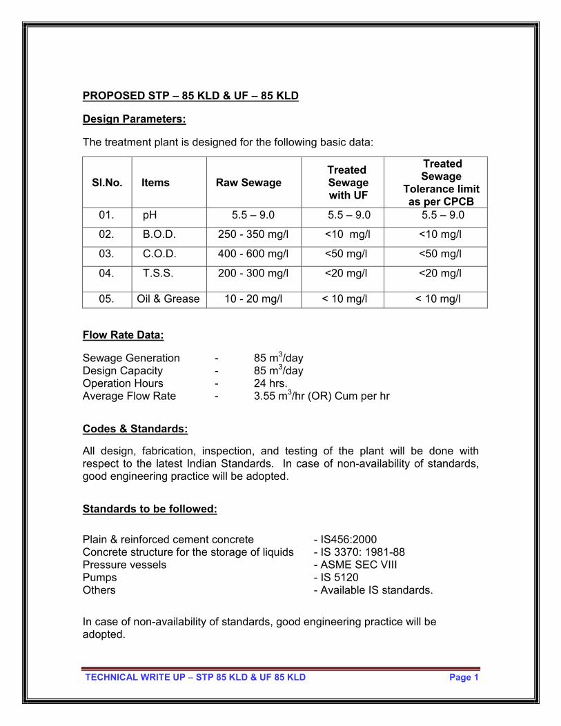
PROPOSED STP – 85 KLD & UF – 85 KLD
Design Parameters:
The treatment plant is designed for the following basic data:
Sl.No. Items Raw Sewage Treated
Sewage with UF
Treated Sewage
Tolerance limit as per CPCB
01. pH 5.5 – 9.0 5.5 – 9.0 5.5 – 9.0
02. B.O.D. 250 - 350 mg/l <10 mg/l <10 mg/l
03. C.O.D. 400 - 600 mg/l <50 mg/l <50 mg/l
04. T.S.S.
200 - 300 mg/l <20 mg/l <20 mg/l
05. Oil & Grease 10 - 20 mg/l < 10 mg/l < 10 mg/l
Flow Rate Data:
Sewage Generation - 85 m3/day Design Capacity - 85 m3/day Operation Hours - 24 hrs. Average Flow Rate - 3.55 m3/hr (OR) Cum per hr
Codes & Standards:
All design, fabrication, inspection, and testing of the plant will be done with respect to the latest Indian Standards. In case of non-availability of standards, good engineering practice will be adopted.
Standards to be followed:
Plain & reinforced cement concrete - IS456:2000 Concrete structure for the storage of liquids - IS 3370: 1981-88 Pressure vessels - ASME SEC VIII Pumps - IS 5120 Others - Available IS standards.
In case of non-availability of standards, good engineering practice will be adopted.

TECHNICAL WRITE UP – STP 85 KLD & UF 85 KLD Page 2
TREATMENT METHODOLOGY
PRINCIPLE
The Sewage Treatment Plant is designed based on Moving Bed Bio Reactor
(MBBR) Process. The sewage treatment process involves the following unit
operations / treatment units as given below.
� Bar Screen Chamber
� Equalization Tank
� MBBR – Aeration Tank - I
� MBBR – Aeration Tank - II
� Secondary Settling Tank
� Clarifier Water Tank
� Filtration through Pressure Sand Filter and Carbon Filter
� Disinfection by chlorination
� Disinfection by UV sterilizer
� Ultra filtration feed tank
� Ultra filtration system
� Ultra filtration treated water tank
� Sludge Holding Tank
� Screw pump
� Filter Press

TECHNICAL WRITE UP – STP 85 KLD & UF 85 KLD Page 3
Bar Screen Chamber
Equalization Tank
Settling Tank
Clarifier Water Tank
UF Feed Tank
Sludge Holding Tank
Filter Press
Hypo Dosing & UV Disinfection
UF System
Aeration Tank (MBBR) – I & II
UF Treated Water Tank
To Toilet Flushing & Gardening
P
P
P
P
Raw Sewage
Dried Sludge for disposal
85KL/Day
Air Supply
Air Blower
Air Supply Filtrate
Activated Carbon Filter
Pressure Sand Filter
85 KL/Day
Air Supply
A A
TECHNICAL WRITE UP – STP 85 KLD & UF 85 KLD Page 4
TREATEMENT SCHEME
PRE TREATMENT SYSTEM – SCREENING
Trash and non-biodegradable solids, such as hair, lint, girt and plastics may foul
or damage the membranes, pumps if allowed to pass into the treatment. To
enhance the long-term operation and effectiveness of the treatment system AE
recommends an internally fed channel screens with 10mm opening with no
possibility of bypass or carryover.
COLLECTION / FLOW EQUALIZATION TANK
The Waste water then flows by gravity into the Collection/Equalization Tank
which is provided with submerged aeration system generally to keep the solids in
suspension and homogeneous conditions and not to allow anaerobic/septic
conditions to set in. Equalization tank shall take care of flow surges and
homogenization. Equalization of sewage is essential to make a uniform mixture
for further treatment. Raw Sewage Transfer Pump operates with help of level
switches.
AERATION TANK - MBBR TANK I & II
From the equalization tank, waste water is constantly pumped into the Moving
Bed Bio Reactor (Aeration tank) where sufficient amount of air is supplied to
oxidize the organics absorbed by the bacterial biomass. Required quantity of air
is supplied and mixing is done by the Diffused Aeration System. The Moving
Bed Bio Reactor is fitted with air diffusers for supply of air and is filled with plastic
media in a fluidized form for providing adequate surface area for bacteria to
oxidize the organics present in the waste.

TECHNICAL WRITE UP – STP 85 KLD & UF 85 KLD Page 5
Aeration tank is the main Reaction tank for the biological process. As the waste
water flows into the tank an equal quantity of the tank contents overflows in to
clarifier / setting tank. Aeration tank is provided with diffused aeration / mixing
system, where in tubular membrane diffuser is provided and are arranged at the
bottom of the tank and air is fed with air blowers provided for aeration operate
continuously round the clock, so long as there is normal waste water flow in to
the tank.
DETAILS OF PLASTIC MEDIA:
PLASTIC MEDIA:
Random packed PP / Plastic media has wide application in biological treatment
systems. The media provides optimum effective surface area for biological
growth. The three dimensional liquid distribution due to unique dimensional
design increases hydraulic Retention time and ensures excellent gas – liquid
distribution within the packed bed reactor, thus enhancing the treatment
efficiency.
When installed in random configuration, it maintains uniform passage of air and
waste water in all direction throughout a 360 deg field. The orientation is such
that no surface generates a continuous vertical or horizontal position.
Material specifications: Constructed from PP / Plastic which is a strong, light
weight and chemically resistant material, also non-toxic to micro organisms. The
formulation adopted is resistant to UV degradation, aging and erosion.
The waste water in the aeration tank utilize the oxygen fed through air blowers and
the micro organism (Bio-Mass) starts growing with attached on top of Plastic Media
using the nutrients present in waste water. The contents of the aeration tank are
called “Mixed liquor and suspended solids as Mixed liquor suspended solids”
(MLSS), which is in fact the active Bio–mass responsible for bio-degradation of the
effluent. The Bio-mass comprises chiefly of bacteria and to some extent lower form
animals such as rotifers and protozoa.
TECHNICAL WRITE UP – STP 85 KLD & UF 85 KLD Page 6
SECONDARY SETTLING TANK:
The overflow from aeration tank is led into the secondary Settling tank by gravity.
The sludge get settles at the bottom of the tank and is directed towards the
sludge well at the center. The sludge collected at the center is pumped to
aeration tank or to Sludge Holding tank by Return sludge Pumps.
Treated Sewage water from secondary settling Tank as overflow shall be lead to
Clarifier water tank.
TERTIARY TREATMENT:
The clear water overflowing from the secondary Settling Tank is collected in a
tank called clarifier water tank. This water is generally have desired
characteristics required for water to be used on irrigation land with 92-95% of
BOD5 removed.
However for reuse and reclamation of treated water for landscaping, gardening,
A/c- make up and toilet flushing, the tertiary treatment is carried out with the
following units, for further reduction in TSS, BOD5, odour and colour.
PRESSURE SAND FILTER (PSF):
The treated water from the sump is pumped to pressure sand filter. This is a
pressure vessel equipped with a perforated under drain plated, filled with filter
media comprising of graded gravel / sand. The suspended particulars are
arrested and the clean filtered water coming out from pressure sand filter is led to
ACF filter for further treatment.

TECHNICAL WRITE UP – STP 85 KLD & UF 85 KLD Page 7
1. The bottom portion of the filter is filled with three layers of pebbles of different
sizes.
a. 1 ½” x 1”
b. 3/4” x 1/2”
c. 1/2” x 3/8”
2. The middle portion of the filter is filled with two types of silex.
a. Coarse silex of size 3/8”x1/4”
b. Fine silex of size 1/4”x1/10”
3. The top portion of the filter is filled with 16/32” filter sand.
The purpose of sand filter is mainly to remove the colloidal impurities/suspended
solids .which is present in the biological treated sewage effluent. The filter back
wash has to be carried out based on the differential pressure between the inlet
and the outlet of the pressure sand filter.
ACTIVATED CARBON FILTER:
The filter water from the PSF passes through the activated carbon filter, which is
again a vertical pressure vessel equipped with perforated plate at the bottom and
bell mouth at the top. In between is the filter media comprising of 500 – 600 mm
activated carbon granules over a bed of graded gravel.
In ACF any odour and to certain extent color in the wastewater is absorbed by
the carbon and the filter water is absolutely sparklingly clear.
1. The bottom portion of the filter is filled with three layers of pebbles of
different sizes.
a. 1 ½” x 1”
b. 3/4” x 1/2”
c. 1/2” x 3/8”
2. The middle portion of the filter is filled with two types of silex.
a. Coarse silex of size 3/8”x1/4”
b. Fine silex of size 1/4”x1/10”
3. The top portion of the filter is filled with Activated carbon.

TECHNICAL WRITE UP – STP 85 KLD & UF 85 KLD Page 8
The purpose of carbon filter is mainly to remove the colloidal trace organics
/neutralized the hypo to maintain residual chlorine which is present in the
biological treated sewage effluent. The filter back wash has to be carried out
based on the differential pressure between the inlet and the outlet of the pressure
carbon filter.
ULTRA VIOLET:
An on line Ultra Violet is provided at the outlet of the ACF, on switching it on it
automatically, this UV System acts as a disinfectant in the filter water and thus
ensuring filtered water is harmless for skin of the persons who come in contact
with it.
CHLORINATION:
A on line chlorinator is provided at the outlet of the ACF, on switching it on it
automatically injects the hypochlorite solution into the filter water coming out of
ACF at desired rate, this hypochlorite solution acts as a disinfectant in the filter
water, Controls Organic matter and thus ensuring filtered water is harmless for
skin of the persons who come in contact with it.
ULTRAFILTRATION:
Ultra filtration or UF is a pressure driven membrane separation process that
separates particulate matter from soluble components in the carrier fluid (such as
water). UF membranes typically have pore sizes in the range of 0.01 - 0.10 µm
and have a high removal capability for bacteria and most viruses, colloids and silt
(SDI).
From the Treated Water tank the water will be pumped to Ultra filtration Plant.
This is designed by using advanced technology with the purpose of removing
micro bacterial counts. Ultra filtration system is also used as a pre treatment to
the reverse osmosis plants. The Ultra filtration work on Dead end flow filtration
principle and designed operates at around 90% recoveries.

TECHNICAL WRITE UP – STP 85 KLD & UF 85 KLD Page 9
The Filtered / Treated water from sewage treatment plant is then passed through
the latest state of the art ultra filtration membranes for the reduction of SDI,
colloidal particles and then bacteriological contamination. The UF membranes
selected are the unique Multi bore Membranes which has the highest mechanical
strength than the single bore membranes. UF membranes are designed with a
flux of 40 - 50 LMH and the membranes are operated in Dead End mode or
Cross Flow. The backwash and the forward flush are let into the inlet of STP
plant for further treatment. The unit is automatic operated through a PLC. This
unit consists of inside cleaning system namely the Caustic and HCl chemicals.
Treated water from the Ultra filtration System shall be stored in UF Permeate
Storage Tank and UF Membranes shall be backwashed frequently.
SLUDGE RECIRCULATION & EXCESS SLUDGE DISPOSAL:
Sludge recirculation system for re circulating settled activated sludge from
secondary settling back to aeration tank and comprising either direct pumping
from secondary settling or pumping from a separate sludge sump into which the
clarifier sludge drains.
The excess sludge generated is collected in a separate tank called aerobic
digester / Sludge Holding tank where in the sludge is further digested &
thickened. The thickened sludge is either put on to sludge drying beds or taken
out as cakes through a Filter press. Such dried sludge is good manure for Plant
and trees.
TREATED WATER TANK:
After UF Treatment, the treated and filtered water is collected in this sump until
used for further disposal for landscaping / gardening and toilet flushing or other
re-use.
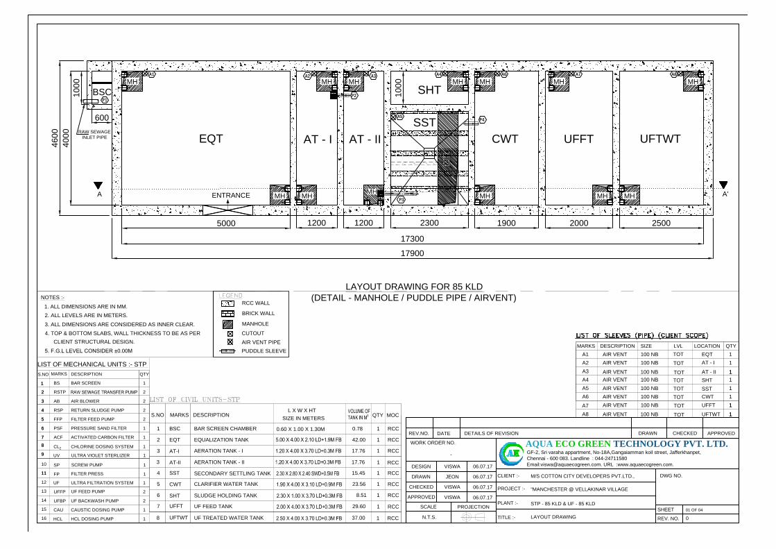
5000 1900 2000
EQT
2300
SHT
CWT UFFT
17900
17300
AT - I
A'
P3
P4
BSC BAR SCREEN CHAMBER
MARKS DESCRIPTION
EQT EQUALIZATION TANK
AERATION TANK - I AT-I
SSTSECONDARY SETTLING TANK
CLARIFIER WATER TANKCWT
SLUDGE HOLDING TANKSHT
L X W X HT
QTY MOC
1
1
1
1
1
1
1
RCC
RCC
RCC
RCC
RCC
RCC
RCC
S.NO
1
2
3
4
5
6
7 UFFTUF FEED TANK
0.78
42.00
17.76
15.45
23.56
8.51
29.60
SIZE IN METERS
SIZE LVL QTY
1
AIR VENT
LOCATION
100 NB
1
MARKS DESCRIPTION
A1
A4
A5
AIR VENT
1
TOT100 NB
A2
AIR VENT 100 NB
1A6 AIR VENT
1
100 NB
AIR VENT 100 NB 1
AT - I
SHT
EQT
UFFT
CWT
AIR VENT 100 NB 1
A3
SST
TOT
TOT
TOT
TOT
TOT
NOTES :-
1. ALL DIMENSIONS ARE IN MM.
2. ALL LEVELS ARE IN METERS.
3. ALL DIMENSIONS ARE CONSIDERED AS INNER CLEAR.
4. TOP & BOTTOM SLABS, WALL THICKNESS TO BE AS PER
CLIENT STRUCTURAL DESIGN.
5. F.G.L LEVEL CONSIDER ±0.00M
LAYOUT DRAWING FOR 85 KLD
(DETAIL - MANHOLE / PUDDLE PIPE / AIRVENT)
RCC WALL
BRICK WALL
MANHOLE
CUTOUT
AIR VENT PIPE
PUDDLE SLEEVE
1200 1200
AT - II
AERATION TANK - IIAT-II
3 17.761
RCC
2500
UFTWT
4600
BSC
RAW SEWAGE
INLET PIPE
600
A
P1
1000
4000
MH MH
MH MH
MH
MHMH
MH
A1 A4
MH
MH
MH
MH
A6
MH
A2 A3 A7 A8
1 RCC8
UFTWTUF TREATED WATER TANK 37.00
LIST OF MECHANICAL UNITS :- STP
2
3
4
5
6
7
8
9
11
RSTP
AB AIR BLOWER
RETURN SLUDGE PUMP RSP
MARKSDESCRIPTION
PRESSURE SAND FILTERPSF
ACTIVATED CARBON FILTERACF
CHLORINE DOSING SYSTEMCL
2
FILTER FEED PUMP FFP
BS BAR SCREEN
S.NO
2
3
4
5
6
7
8
UFFP
10
UF FEED PUMP
ULTRA FILTRATION SYSTEMUF
9
HCL DOSING PUMP HCL
14
CAUSTIC DOSING PUMP CAU
13
12
UF BACKWASH PUMPUFBP
11
15
16
QTY
1
2
2
2
2
1
1
1
2
1
1
1
2
11
FPFILTER PRESS
SCREW PUMPSP
1
1
ULTRA VIOLET STERLIZERUV 1
0.60 X 1.00 X 1.30M
1AIR VENT 100 NB
A7
1UFTWTTOT
1AIR VENT 100 NB
A8
1AT - IITOT
P2
ENTRANCE
PLANT :-
PROJECT :-
CLIENT :-
WORK ORDER NO.
N.T.S.
DESIGN
GF-2, Sri varaha appartment, No-18A,Gangaiamman koil street, Jafferkhanpet,
Chennai - 600 083. Landline : 044-24711580
Email:[email protected]. URL :www.aquaecogreen.com.
TITLE :-
PROJECTIONSCALE
DRAWN
APPROVED
CHECKED
SHEET
REV. NO.
DWG NO.
AQUA ECO GREEN TECHNOLOGY PVT. LTD.REV.NO. DATE DETAILS OF REVISION DRAWN CHECKED APPROVED
JEON
-
0
LAYOUT DRAWING
VISWA
VISWA
06.07.17VISWA
STP - 85 KLD & UF - 85 KLD
06.07.17
06.07.17
06.07.17
"MANCHESTER @ VELLAKINAR VILLAGE
M/S COTTON CITY DEVELOPERS PVT.LTD.,
01 OF 04
1000
SST
A5
MH

SIZE LVL QTY
1
AIR VENT
LOCATION
100 NB
1
MARKS DESCRIPTION
A1
A4
A5
AIR VENT
1
TOT100 NB
A2
AIR VENT 100 NB
1A6 AIR VENT
1
100 NB
AIR VENT 100 NB 1
AT - I
SHT
EQT
UFFT
CWT
AIR VENT 100 NB 1
A3
SST
TOT
TOT
TOT
TOT
TOT
NOTES :-
1. ALL DIMENSIONS ARE IN MM.
2. ALL LEVELS ARE IN METERS.
3. ALL DIMENSIONS ARE CONSIDERED AS INNER CLEAR.
4. TOP & BOTTOM SLABS, WALL THICKNESS TO BE AS PER
CLIENT STRUCTURAL DESIGN.
5. F.G.L LEVEL CONSIDER ±0.00M
LAYOUT DRAWING FOR 85 KLD
(DETAIL - PUMP ROOM)
RCC WALL
BRICK WALL
MANHOLE
CUTOUT
AIR VENT PIPE
PUDDLE SLEEVE
1AIR VENT 100 NB
A7
1UFTWTTOT
1AIR VENT 100 NB
A8
1AT - IITOT
PLANT :-
PROJECT :-
CLIENT :-
WORK ORDER NO.
N.T.S.
DESIGN
GF-2, Sri varaha appartment, No-18A,Gangaiamman koil street, Jafferkhanpet,
Chennai - 600 083. Landline : 044-24711580
Email:[email protected]. URL :www.aquaecogreen.com.
TITLE :-
PROJECTIONSCALE
DRAWN
APPROVED
CHECKED
SHEET
REV. NO.
DWG NO.
AQUA ECO GREEN TECHNOLOGY PVT. LTD.REV.NO. DATE DETAILS OF REVISION DRAWN CHECKED APPROVED
JEON
-
0
LAYOUT WITH PUMP ROOM DRAWING
VISWA
VISWA
06.07.17VISWA
STP - 85 KLD & UF - 85 KLD
06.07.17
06.07.17
06.07.17
02 OF 04
RSTP
AB
SP
FP
FFP
PSF ACF
UF
CAU
HCL
PANEL
UV
B'
B
1900 2000
EQT
2300
SHT
CWT UFFT
17900
17300
AT - I
A'
P3
P4
1200 1200
AT - II
2500
UFTWT
4600
BSC
RAW SEWAGE
INLET PIPE
600
A
P1
1000
4000
MH MH
MH MH
MH
MHMH
MHMH
MH
MH
MHMH
P2
ENTRANCE
SST
MH
UFFP
UFBP
RSP
CL2
DOWN
WINDOW WINDOW
WINDOW WINDOW
WINDOW
WINDOW
BSC BAR SCREEN CHAMBER
MARKS DESCRIPTION
EQT EQUALIZATION TANK
AERATION TANK - I AT-I
SSTSECONDARY SETTLING TANK
CLARIFIER WATER TANKCWT
SLUDGE HOLDING TANKSHT
L X W X HT
QTY MOC
1
1
1
1
1
1
1
RCC
RCC
RCC
RCC
RCC
RCC
RCC
S.NO
1
2
3
4
5
6
7 UFFTUF FEED TANK
0.78
42.00
17.76
15.45
23.56
8.51
29.60
SIZE IN METERS
AERATION TANK - IIAT-II
3 17.761
RCC
1 RCC8
UFTWTUF TREATED WATER TANK 37.00
LIST OF MECHANICAL UNITS :- STP
2
3
4
5
6
7
8
9
11
RSTP
AB AIR BLOWER
RETURN SLUDGE PUMP RSP
MARKSDESCRIPTION
PRESSURE SAND FILTERPSF
ACTIVATED CARBON FILTERACF
CHLORINE DOSING SYSTEMCL
2
FILTER FEED PUMP FFP
BS BAR SCREEN
S.NO
2
3
4
5
6
7
8
UFFP
10
UF FEED PUMP
ULTRA FILTRATION SYSTEMUF
9
HCL DOSING PUMP HCL
14
CAUSTIC DOSING PUMP CAU
13
12
UF BACKWASH PUMPUFBP
11
15
16
QTY
1
2
2
2
2
1
1
1
2
1
1
1
2
11
FPFILTER PRESS
SCREW PUMPSP
1
1
ULTRA VIOLET STERLIZERUV 1
0.60 X 1.00 X 1.30M
"MANCHESTER @ VELLAKINAR VILLAGE
M/S COTTON CITY DEVELOPERS PVT.LTD.,

WL-1.15M
2400 S
WD
WL-0.15M
WL+0.45M
EQT
AT
-I
SST
CWT UFFT
5000 1200 1900 2000
17300
17900
1800
600
PCC
PCC
4000
2100 LD
1900 F
B
3700 S
WD
3100 LD
900
3700 LD
300
BSC
C1
P3
500
TUBE SETTLER MEDIA
RAW SEWAGE
INLET PIPE
P4
PUMP ROOM
LVL -3.25M
FFL 0.00M
LVL+4.00M
3000 C
LR
.H
T
1200
AT
-II
WL+0.45MWL+0.45M
SECTION DRAWING FOR 85 KLD
(DETAIL - SECTION - AA')
3700 S
WD
2500
WL+0.45M
3700 LD
300
2300
UFTWT
P1
P2
MH MH MH MH MH MH
WINDOWDOOR
NOTES :-
1. ALL DIMENSIONS ARE IN MM.
2. ALL LEVELS ARE IN METERS.
3. ALL DIMENSIONS ARE CONSIDERED AS INNER CLEAR.
4. TOP & BOTTOM SLABS, WALL THICKNESS TO BE AS PER
CLIENT STRUCTURAL DESIGN.
5. F.G.L LEVEL CONSIDER ±0.00M
RCC WALL
BRICK WALL
MANHOLE
CUTOUT
AIR VENT PIPE
PUDDLE SLEEVE
PLANT :-
PROJECT :-
CLIENT :-
WORK ORDER NO.
N.T.S.
DESIGN
GF-2, Sri varaha appartment, No-18A,Gangaiamman koil street, Jafferkhanpet,
Chennai - 600 083. Landline : 044-24711580
Email:[email protected]. URL :www.aquaecogreen.com.
TITLE :-
PROJECTIONSCALE
DRAWN
APPROVED
CHECKED
SHEET
REV. NO.
DWG NO.
AQUA ECO GREEN TECHNOLOGY PVT. LTD.REV.NO. DATE DETAILS OF REVISION DRAWN CHECKED APPROVED
JEON
-
0
SECTION - AA'
VISWA
VISWA
06.07.17VISWA
STP - 85 KLD & UF - 85 KLD
06.07.17
06.07.17
06.07.17
03 OF 04
4500
LVL+1.00M
BSC BAR SCREEN CHAMBER
MARKS DESCRIPTION
EQT EQUALIZATION TANK
AERATION TANK - I AT-I
SSTSECONDARY SETTLING TANK
CLARIFIER WATER TANKCWT
SLUDGE HOLDING TANKSHT
L X W X HT
QTY MOC
1
1
1
1
1
1
1
RCC
RCC
RCC
RCC
RCC
RCC
RCC
S.NO
1
2
3
4
5
6
7 UFFTUF FEED TANK
0.78
42.00
17.76
15.45
23.56
8.51
29.60
SIZE IN METERS
AERATION TANK - IIAT-II
3 17.761
RCC
1 RCC8
UFTWTUF TREATED WATER TANK 37.00
LIST OF MECHANICAL UNITS :- STP
2
3
4
5
6
7
8
9
11
RSTP
AB AIR BLOWER
RETURN SLUDGE PUMP RSP
MARKSDESCRIPTION
PRESSURE SAND FILTERPSF
ACTIVATED CARBON FILTERACF
CHLORINE DOSING SYSTEMCL
2
FILTER FEED PUMP FFP
BS BAR SCREEN
S.NO
2
3
4
5
6
7
8
UFFP
10
UF FEED PUMP
ULTRA FILTRATION SYSTEMUF
9
HCL DOSING PUMP HCL
14
CAUSTIC DOSING PUMP CAU
13
12
UF BACKWASH PUMPUFBP
11
15
16
QTY
1
2
2
2
2
1
1
1
2
1
1
1
2
11
FPFILTER PRESS
SCREW PUMPSP
1
1
ULTRA VIOLET STERLIZERUV 1
0.60 X 1.00 X 1.30M
WINDOW
"MANCHESTER @ VELLAKINAR VILLAGE
M/S COTTON CITY DEVELOPERS PVT.LTD.,
MH

TOTAL OSR AREA
3186.41 SQM
MAIN ENTRY
1
2
3
4
5
20
22
9
10
11
14
19
16
21
23
28
12
15
18
27
29
41
31
34
39
40
38
42
76
75
73
74
32
37
43
45
51
50
49
48
52
54
55
56
64
63
61
60
65
66
67
68
77
78
79
81
82
72
70
69
59
58
47
EBROOM
GENSETROOM
S.T.P
TRANS
FORMER
YARD
24
33
36
DRIVE WAY
SWIMMING POOL & CLUB HOUSE
46
57
Security Room
To Mettupalayam Road
To Vellakinar
13.91M WIDE EXISTING ROAD
47
SITE PLAN SHOWING THE GREENBELT DEVELOPMENT FOR THE PROPOSED RESIDENTIAL GROUP HOUSING BUILDINGS IN S.F. Nos.410 / 2E,
418 / 2, 419 / 1B, 419 / 1A2 & 420 / 3B AT VELLAKINAR VILLAGE,COIMBATORE NORTH TALUK & COIMBATORE CORPORATION.EL
ECTR
ICA
L TR
AN
SFO
RMER
RO
OM
W
.
M
.
P
6
7
30
25
RWH
23.61
Greenbelt around periphery - 1070.35 x 1.52 = 1626.93 sqm
LEGEND :
Greenbelt along Internal Road - 1160.58 x 1.21 = 1404.30 sqm
Greenbelt area provided around villas = 4942.09 sqm
Total Greenbelt Area = 8313.72 Sqm
Greenbelt area provided around E.W.S Block = 340.40 sqm
HT Line AREA
1315.16 SQM
Greenbelt Area provided under H.T. Line Area = 1315.16 Sqm

ANNEXURE II
RAINWATER HARVESTING
It is proposed to recharge the surface runoffs from the landscape areas and other lined &
unlined areas into the ground by recharging pits located all through the site. The storm water
from all these places will be collected by the storm water drains.
Rainwater Runoff Calculations
DescriptionArea in
SqmCoefficient
Runoff
RainfallIntensity in
m/hr
RainwaterRunoffCum/yr
Road Area 10314.26 0.85 0.5 4383.56
GreenbeltArea
4605.30 0.3 0.5 690.795
Roof Area 10306.51 0.9 0.5 4637.92
Total volume of rainwater runoff 9712.275
Considering Peak Rainfall 50 mm/hr,
Roof Run-off = (10306.51 x 0.9 x 0.050)
= 463.79 m3 will be collected in storage sump.
Runoff from Landscape area & road area will be used to recharge the ground water table.
Based on soil investigation report, number of percolation/ recharge pits will be calculated.
Excess runoff will be drained into the external storm water drain outside the site.
Recharge Pit – 12 Nos.
12 Nos of circular recharge pits are proposed to construct in the premises. Rain water falling
over the roads & pavement area and the open area will be used for recharging the ground
water. The diameter of pit is 2.0 m with 2.5 m depth and an additional freeboard of 0.5m. The
2.5 m pit is filled with 0.5 m of boulders, 0.5 m of 40 mm jelly stone, 0.5 m of 20 mm jelly
stone and 0.5 m of coarse sand and 20 mm jelly stone equally layered at the top. The rest of
the space is left free for rain water to percolate. 200 mm dia perforated PVC pipe is provided
upto the depth of sub soil level. The pit is covered with precast perforated slab and acts as
manhole. The cross section of the recharge pit is shown as below;


