miller cycle engine management system and its distinctive feature
TRANSCRIPT
ELSEVIER JSAE Review 15 (1994) 305 3t)8
Miller cycle engine management system and its distinctive feature
Ryo Shimizu a, Masaki Fujii h, Takasi Suzuki ", Masao Inoue c, Susumu Niinai d ' Powertrain Det'elopment Department, Mazda Motor Corporation 3-1 Shinchi, Fuehu-cho, Aki-gun, Hiroshima. 73~) 91 .lapan
h Vehicle Engineering Administration Department, Mazda Motor Corporation 3-l Shinchi, Fuehu<'ho, Aki-gun, Hiros'hima. 7.?0 91 .lapan Vehicle Testing & Research Department, No. 1, Mazda Motor Corporation 3~1 Shinehi. Fuchu-cho, Aki-gun, Hiroshima, 730 91 ,lapan d Product Quality Administration Department. Mazda Motor Corporation 3-1 Shinchi. Fuchu-cho. Aki-gun, Hiroshima. 730 91 ,lapan
Received 16 June 1994
Abstract
Mazda has developed a Miller Cycle Engine which realizes high expansion ratio and high boost by delaying the closing timing of the intake valves combined with Lysholm Compressor. At the same time we has developed its Engine Management System which has balanced a excelent fuel economy and high engine torque. This report will focus on the distinctive feature of this system and its unique Air Bypass Valve Control.
1. Introduction
As social perception for global environmental protec- tion has grown, in recent years, especially in view of preventing the greenhouse effect, non-CO 2 emitting and fuel economy have become top priorities for automobile manufacturers. On the other hand, people's interest for high-class cars has been gradually flagged due to the economic recession, their interests which represent wealthy living have never been stopped. We must make every endeavour to satisfy the above mentioned demands.
The engines are required to realize both high torque which produces smooth driving and good fuel economy. Conventional engines were developed to satisfy these two conflicting demands.
To improve drastically the balance, we have success- fully developed the Miller Cycle Gasoline Engine which adopts the late closing timing of intake valves and Lysholm Compressor (" L / C " ) .
In this paper, we describe the distinctive feature of this new engine and the overview of control system which was established to take every advantage of the engine.
2. Development aims
In developing the KJ-ZEM (Miller Cycle Engine), the most outstanding aim is to realize fuel economy and driving performance that cannot be obtained with the
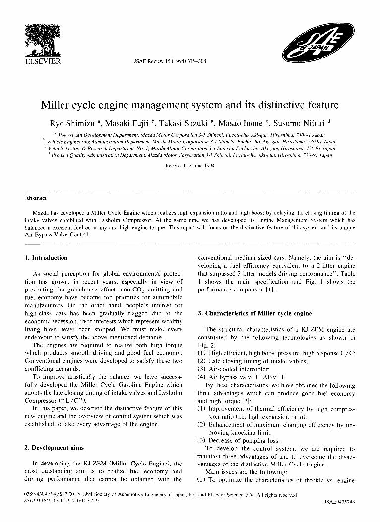
conventional medium-sized cars. Namely, the aim is "'de- veloping a fuel efficiency equivalent to a 2-litter engine that surpassed 3-litter models driving performance". Table 1 shows the main specification and Fig. 1 shows the performance comparison [1].
3. Characteristics of Miller cycle engine
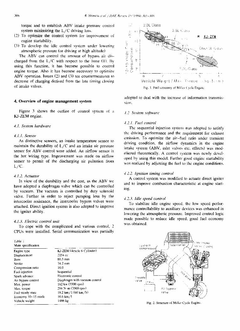
The structural characteristics of a KJ-ZEM engine are constituted by the following technologies as shown in Fig. 2: (1) High efficient, high boost pressure, high response L/C: (2) Late closing timing of intake valves: (3) Air-cooled intercooler; (4) Air bypass valve ('~ABV").
By these characteristics, we have obtained the following three advantages which can produce good fuel economy and high torque [2]: (1) Improvement of thermal efficiency by high compres-
sion ratio (i.e. high expansion ratio). (2) Enhancement of maximum charging efficiency by im-
proving knocking limit, (3) Decrease of pumping loss.
To develop the control system, we are required to maintain three advantages of and to overcome the disad- vantages of the distinctive Miller Cycle Engine.
Main issues are the following: (1) To optimize the characteristics of throttle vs. engine
0389-4304/94/$07.00 ~': 1994 Society of Automotive Engineers of Japan, Inc. and Elsevier Science B.V. All rights reserved SSDI 0 3 8 9 - 4 3 0 4 ~ 4 ) 0 0 0 3 7 - 9 JSAE9435748
306 R. Sh imtzu ct ul. / .ISA E Res u'~* t ~ ( / 794j ;05---~0k,'
torque and to establish ABV intake pressure control system minimizing the L / C driving loss.
(2) To optimize the control system for improvement of engine startability.
(3) To develop the idle control system under lowering atmospheric pressure (or driving at high altitude)
The ABV can control the amount of bypass air dis- charged from the L / C with respect to the issue (1). Bv using this function, it has become possible to control engine torque. Also it has become necessary to optimize ABV operation. Issues (2) and (3) are countermeasures to decrease of charging derived from the late timing closing of intake valves.
/".
L L_ -, o ~!
~:: E 8 LS~ 03
C • o 7
( . )
2 0 L C lass
--.,_ ~ 2 !~L-i., as.~
~ ,~, ~ K J - ZEId
i - . ' 5 ) V ~ , ( ) ~3<$ '-
! '~ ? t -C lass
8 -? l
b4 a . .. - V e h i c l e W e i g h t ' , : , : : : rq t ie { ~<::, "~ r : : )
Fig. 1. Fuel economy of Miller ('ycle Engine.
4. Overview of engine management system adopted to deal with the increase of information transmis- sion.
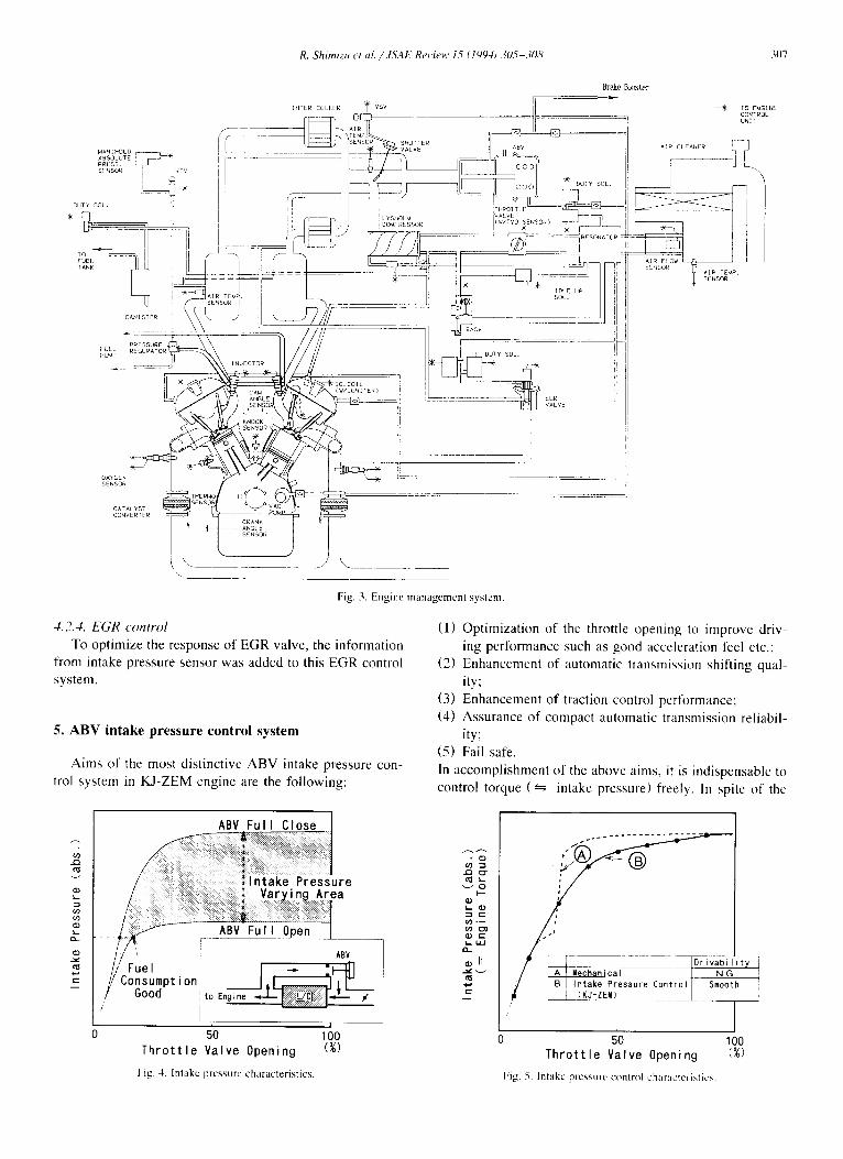
Figure 3 shows the outline of control system of :t
KJ-ZEM engine.
4.1. System hardware
4.1.1. Sensor As distinctive sensors, an intake temperature sensor to
maintain the durability of L / C and an intake air pressure sensor for ABV control were added. An airflow sensor is the hot wiring type. Improvement was made on airflow sensor to permit of the discharging air pulsation from L/C.
4.1.2. Actuator In view of the durability and the cost, as the ABV we
have adopted a diaphragm valve which can be controlled by vacuum. The vacuum is controlled by duty solenoid valve. Further in order to reject pumping loss by the intercooler resistance, the intercooler bypass valves were attached. Direct ignition system is also adopted to improve the igniter ability.
4.1.3. Electric control unit To cope with the complicated and various control, 2
CPUs were installed. Serial communication was partially
Table 1 Main specification
Engine type KJ-ZEM (4cycle 6-Cylinder) Displacement 2254 cc Bore 80.3 mm Stroke 74.2 mm Compression ratio 10.0 Fuel injection Sequential Spark advance Electronic control Air bypass control Diaphragm with vacuum control Max. power 162 kw (5500 rpm) Max. torque 294 N. m (3500 rpm) Fuel steady state 18.2 kin/1 (60 kin/h) Economy 10-15 mode 10.6 km/ l Vehicle weight 1486 kg
4.2. System software
4.2.1. Fuel control The sequential injection system was adopted to satisfy
the driving performance and the requirement for exhaust emission. To optimize the air-fuel ratio under transient driving condition, the airflow dynamics in the engine intake system (ABV, inlet valves etc. effects) was mod- eliezed theoretically. A control system was newly devel- oped by using this model. Further good engine startability was realized by adjusting the fuel to the engine conditions.
4.2.2. Ignition timing control A control system was modified to actuate direct igniter
and to improve combustion characteristic at engine start- ing.
4.2..3. Idle speed control To stabilize idle engine speed, the low speed perfor-
mance controllability to auxiliary devices was enhanced in lowering the atmospheric pressure. Improved control logic made possible to reduce idle speed, good fuel economy was obtained.
' ~ \ j
Fig. 2. Structure of Mi l ler Cycle Engine,
R, Shimizu et al. /.ISAI: ReHew 15 11994) 305-308 31)7
M A N I H O L D ABSOLUTE PRESS. SFNSOR
DUTY S O t .
TO : FUEL TANK
F U E - PUMO
OXYGEN SENSOR
¢sv
INTER COLLER vsv
Brake Er~ster
; ! i ....... I COMPRESSOR b
IDLE kip SOL.
~B~CV
I
EGR VALVE
--~K~ TO EMGINE CONTROL U N I T
AIR TEMP. SENSOR
CATALYST CONVERTER
Fig. 3. Engine management system.
4.2 .4 . E G R c o n t r o l
To optimize the response of EGR valve, the information from intake pressure sensor was added to this EGR control system.
5. A B V intake pressure control system
Aims of the most distinctive A B V intake pressure con- trol system in KJ-ZEM engine are the following:
(1) Optimization of the throttle opening to improve driv- ing performance such as good acceleration feel etc.;
(2) Enhancement of automatic transmission shifting qual- ity;
(3) Enhancement of traction control performance: (4) Assurance of compact automatic transmission reliabil-
ity; (5) Fail safe. In accomplishment of the above aims, it is indispensable to control torque ( ~ intake pressure l freely. In spite of the
k-
g ~9
X - i X .
Jre ,h a
50 1 O0
AB7
T h r o t t l e V a l v e Opening (%)
Fig. 4. Intake pressurL' characteristics.
~ g ~ L
e ~ . - -
Q~ C :~- U . l
IX.
J 50 1 O0
T h r o t t l e V a l v e Opening (~)
Fig. 5. Intake pressure control characteristics.
308 R. Shimizu et al../,ISAI=" Rerie~ 15 ¢•994) 305-308
- I I. [
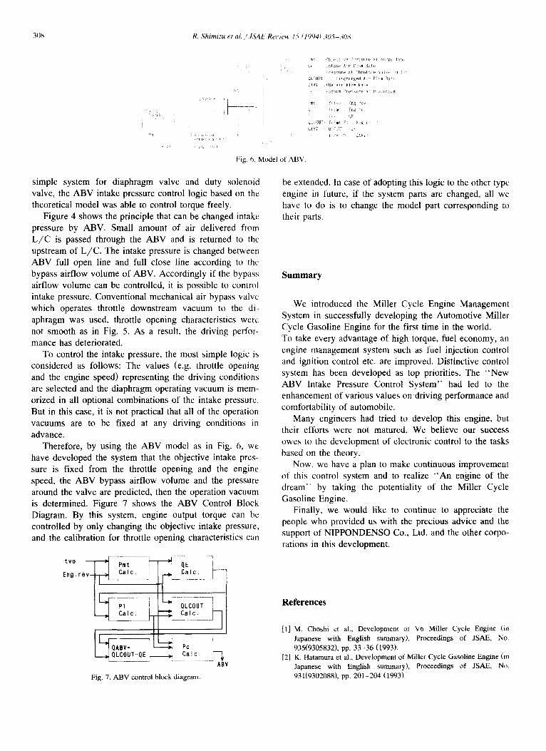
Fig. 6, Model of ABV.
vi l l t a k e a r Flow Rate
! i P r e s s u r e a t T h r , , t ~ h ~ l v , . (tl , t
LJiCO[!~:[, ( I~ i scharged A i r FI ~ Rat~:
4~,RV :AB~ Air Flow Rate
~ t f t , . ~ng re~
~i OUT- f~i'm~ PI . . . . l e .
simple system for diaphragm valve and duty solenoid valve, the ABV intake pressure control logic based on the theoretical model was able to control torque freely.
Figure 4 shows the principle that can be changed intake pressure by ABV. Small amount of air delivered from L / C is passed through the ABV and is returned to the upstream of L /C . The intake pressure is changed between ABV full open line and full close line according to the bypass airflow volume of ABV. Accordingly if the bypass airflow volume can be controlled, it is possible to control intake pressure. Conventional mechanical air bypass valve which operates throttle downstream vacuum to the di- aphragm was used, throttle opening characteristics were not smooth as in Fig. 5. As a result, the driving perfor- mance has deteriorated.
To control the intake pressure, the most simple logic is considered as follows: The values (e.g. throttle opening and the engine speed) representing the driving conditions are selected and the diaphragm operating vacuum is mem- orized in all optional combinations of the intake pressure. But in this case, it is not practical that all of the operation vacuums are to be fixed at any driving conditions in advance.
Therefore, by using the ABV model as in Fig. 6, we have developed the system that the objective intake pres- sure is fixed from the throttle opening and the engine speed, the ABV bypass airflow volume and the pressure around the valve are predicted, then the operation vacuum is determined. Figure 7 shows the ABV Control Block Diagram. By this system, engine output torque can be controlled by only changing the objective intake pressure, and the calibration for throttle opening characteristics can
Eng. r o v ~ - - ~ ae i
QLco-i ,
0 A , v = Pc
ABV
Fig. 7. ABV control block diagram.
be extended. In case of adopting this logic to the other type engine in future, if the system parts are changed, all we have to do is to change the model part corresponding to their parts.
Summary
We introduced the Miller Cycle Engine Management System in successfully developing the Automotive Miller Cycle Gasoline Engine for the first time in the world. To take every advantage of high torque, fuel economy, an engine management system such as fuel injection control and ignition control etc. are improved. Distinctive control system has been developed as top priorities. The "New ABV Intake Pressure Control System" had led to the enhancement of various values on driving performance and comfortability of automobile.
Many engineers had tried to develop this engine, but their efforts were not matured. We believe our success owes to the development of electronic control to the tasks based on the theory.
Now, we have a plan to make continuous improvement of this control system and to realize " A n engine of the dream" by taking the potentiality of the Miller Cycle Gasoline Engine.
Finally, we would like to continue to appreciate the people who provided us with the precious advice and the support of NIPPONDENSO Co., Ltd. and the other corpo- rations in this development.
References
[1] M. Choshi ct al., Development of V6 Miller Cycle Engine (in Japanese with English summary), Proceedings of JSAE, No. 935(9305832), pp. 33-36 (1993).
[2] K. Hatamura et al., Development of Miller Cycle Gasoline Engine (in Japanese with English summary), Proceedings of JSAE, No, 931(9302088), pp. 201-204 (1993)r