mipi 技术及物理层测试的挑战 -...
TRANSCRIPT
MIPI 技术及物理层测试的挑战
Page 1
–是德科技(Keysight)携手MIPI联盟和Synopsys共同推动MIPI技术发展
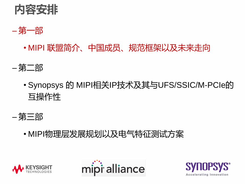
内容安排
–第一部
• MIPI 联盟简介、中国成员、规范框架以及未来走向
–第二部
• Synopsys 的 MIPI相关IP技术及其与UFS/SSIC/M-PCIe的
互操作性
–第三部
• MIPI物理层发展规划以及电气特征测试方案

MIPI联盟—移动及相关产业的接口规范
演讲人
MIPI联盟-总经理皮特.莱弗金
Copyright © 2013 MIPI Alliance. All rights reserved.

MIPI 概述• MIPI联盟是致力于发展移动及相关产业接口规范的国际组织
– MIPI规范为移动手机及其他设备的运行提供基础的接口解决方案
– 现代的移动生态系统包括平板电脑、笔记本电脑、以及其他设备
• MIPI联盟成立于2003年,目前在世界范围内有275家企业成员
– 企业成员包括:手机设备制造商、外围设备制造商、软件提供商、半导体公司、应用程序处理器开发人员、知识产权提供商、测试和测试设备公司、相机、平板和笔记本电脑制造商。
• MIPI有14个活跃的工作组
– 模拟控制接口、电池接口、相机、调试、展示、低延迟接口、LML、市场营销、实体、无线电频、前端、传感器、软件及其同类、测试工作组以及UniPro
• 联盟已经推行了超过45项移动生态系统规范
• MIPI联盟的战略合作伙伴包括:
– JEDEC, PCI-SIG®, MEMS Industry Group®, USB-IF, VESA
Copyright © 2014 MIPI Alliance. All rights reserved.
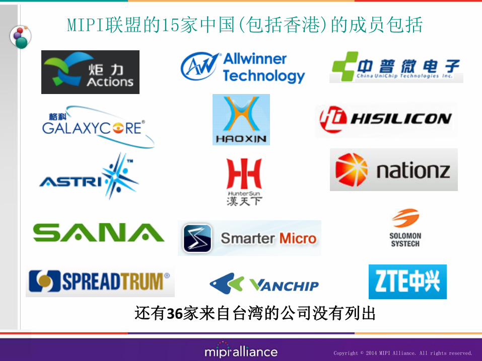
MIPI联盟的15家中国(包括香港)的成员包括
Copyright © 2014 MIPI Alliance. All rights reserved.
还有36家来自台湾的公司没有列出

我们将在上海举行年度会议
• MIPI联盟开放与演示日将于10月9日(09:00 – 15:00)在上海举行
– 向所有的非会员、会员、媒体和分析师免费开放
– 关于MIPI规范的演讲(涉及物理层、传感器、SoundWire、CSI以及DSI)
– 演示日将与开放日同期举行,现场将演示各种MIPI产品
• 如果您对该活动感兴趣,可通过以下网址在线注册:http://www.cvent.com/d/n4q5sq
Copyright © 2014 MIPI Alliance. All rights reserved.

Copyright © 2014 MIPI Alliance. All rights reserved.
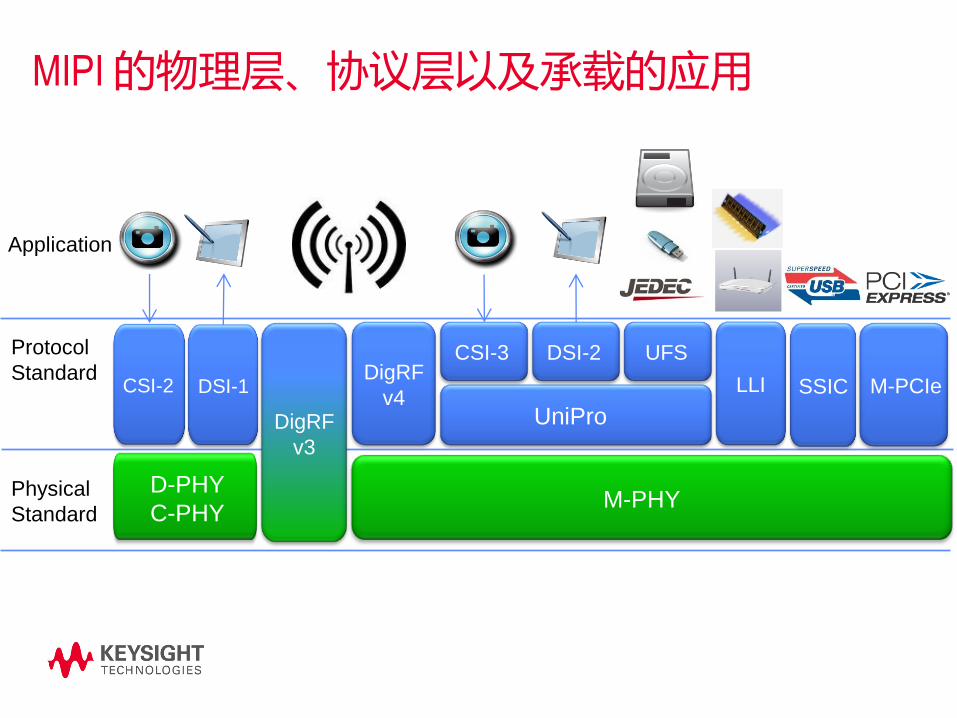
MIPI系统图

MIPI规范架构包括:多媒体、数据/控制、跟踪调试、芯片间的通信
Copyright © 2014 MIPI Alliance. All rights reserved.
RFFE - RF Front End
eTrak - Envelope Tracking
SPMI - Power Mgmt
BIF - Battery
UFS - Storage
DSI - Display
CSI - Camera
SLIMbus, SoundWire - Audio
SPP - SneakPeek Protocol
NIDnT - Narrow Interface for Debug & Trace
TWP - Trace Wrapper Protocol
STP - System Trace Protocol
UniPort-M (UniPro on M-PHY)
LLI – Low Latency Interface (on M-PHY)
M-PCIe – Mobile PCI Express (PCIe on M-PHY)
SSIC – SuperSpeed InterChip (USB3 on M-PHY)

关于MIPI实体规范的新闻稿将于9月17日发布
• MIPI联盟推出MIPI C-PHY与D-PHY的更新——新规范的发布将扩展MIPI联盟为移动及相关产业应用所提供物理层级规范的家族
• 今天MIPI推出新的MIPI C-PHY
– 扩展了MIPI联合会 的物理层级规范,拓宽了生产商们的接口选择,同时也为公司基于特定商业策略或技术要求的差异化产品设计,提供了新的机遇
– 专为程序处理器连接相机和显示模块设计
• 更新了1.2版本的D-PHY以及3,1版本的M-PHY
• 1.0版本MIPI C-PHY 、1.2版本的D-PHY以及3,1版本的M-PHY现在对MIPI联合会成员开放
Copyright © 2014 MIPI Alliance. All rights reserved.
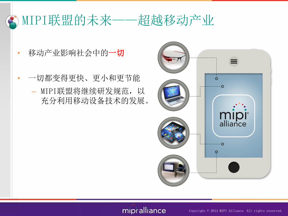
MIPI联盟的未来——超越移动产业
• 移动产业影响社会中的一切
• 一切都变得更快、更小和更节能
– MIPI联盟将继续研发规范,以充分利用移动设备技术的发展。
Copyright © 2014 MIPI Alliance. All rights reserved.
总结
• 在2014~2015这两年里,中国将成为MIPI联盟的最新战略重点地区,为更多想加入MIPI联盟的中国公司提供机会,同时希望中国公司能够在MIPI未来发展方向上做出贡献。
• MIPI联盟将于10月9日在上海举办首个中国开放和演示日。
― 届时,将对所有提前在线注册的MIPI会员和非会员,媒体,分析师以及相关企业、个人和业界专业人士免费开放。
― 开放日将为MIPI的会员们提供一个公开交流的平台和机会,并针对非会员和媒体设置了问答环节。
• 我相信在未来,MIPI联盟将会研发出更多先进的、更创新的标准和规范。
Copyright © 2014 MIPI Alliance. All rights reserved.

谢谢
如需了解更多关于MIPI联盟的常见问题以及会员申请等详情,请按照以下方式联系MIPI联合会总经理皮特.莱弗金先生。
Peter Lefkin – Managing Director [email protected]
Telephone: +1 732 562 3802
www.mipi.org
Copyright © 2014 MIPI Alliance. All rights reserved.

–第一部
• MIPI 联盟简介、中国成员、规范框架以及未来走向
–第二部
• Synopsys 的 MIPI相关IP技术及其与UFS/SSIC/M-PCIe的
互操作性
–第三部
• MIPI物理层发展规划以及电气特征测试方案
内容安排

Synopsys DesignWare MIPI IP
Haopeng Liu
September, 17, 2014
14

Application ProcessorBaseband IC
DesignWare MIPI IPConnectivity IP Between Various ICs
DS
I2G/3G RF IC
DigRF 3G
Slave
DigRF 3G
DigRF v4
Master4G RF IC
DigRF v4
SlaveDigRF v4
M-P
HY
LLI
M-P
HY M
-PH
Y
M-P
HY
3G
PH
Y
CSI-2
Host
DSI
Host
D-PHY D-PHY
LLILLI
DigRF 3G
Master
3G
PH
Y
SS
IC \
M-P
CIe
Ho
st
M-P
HY
Companion IC
M-P
HY
SS
IC \
M-P
CIe
D
evic
e
M-P
HY
Storage IC
SSIC
M-PCIe
UFS
Un
iPro
UF
S H
ost
CS
I-2
Un
iPro
UF
S
Devic
e
Ima
ge
Se
ns
or
D-PHY
CSI-2
Device
Dis
pla
y
D-PHY
DSI
Device
M-P
HY
Current portfolio
M-P
HY
SS
IC /
M-P
CIe
D
evic
e
SS
IC /
/M-P
CIe
Ho
st
M-P
HY SSIC
M-PCIe
M-P
HY
ARA Module
UniPort-M
Un
iPro
Un
iPro
Ap
plicati
on
M-P
HY
Ap
plicati
on

Optimized and Flexible D-PHYSupports 2.5G speeds, ½ the area and power
– D-PHY v1.2 specification
• 2.5Gbps/lane
• Power, Area and Performance Optimized
• Variety of configurations
• DSI Host, CSI2 Device
• CSI2 Host, DSI Device
• Different # of data lanes available
• Interoperable and Integrated with Synopsys
CSI2 and DSI controllers
• Low risk and quick time to market
• Available in 16nm and 28nm
Rx
D-PHY PP
I
Inte
rfac
e
Blo
ck
PP
I
Inte
rfac
e
Blo
ckD-PHY
w/ PLL
Tx D-PHY
Rx D-PHY
DSI Host
CSI2 Device
CSI2 Host
DSI Device

DesignWare UFS v2.0 for Mobile AppsFuture Proof, Interoperable Host and Device Solution
CDinDoutC
UniPro v1.60
Fully Verified, Flexible
RMMI
Silicon-Proven M-PHY HS-Gear3 B
UFS Host v2.00
Fully Verified, Gear3
UFS Software Drivers
Linux, OS-less
Future Proof
M-PHY, UFS IP
Power Modes
Compact and Configurable
Host and Device Customers
Prototyping System
Deployed
Source: Samsung
presentation, JEDEC
Mobile Forum May 2013

Synopsys M-PHY Interoperablew/ UFS, SSIC, M-PCIe
• M-PCIe Controller and
MIPI Gear3 M-PHY
• Compliant USB SSIC
with M-PHY
• Interoperable with
TWO different UFS
devices

内容安排
–第一部
• MIPI 联盟简介、中国成员、规范框架以及未来走向
–第二部
• Synopsys 的 MIPI相关IP技术及其与UFS/SSIC/M-PCIe的
互操作性
–第三部
• MIPI物理层发展规划以及电气特征测试方案

MIPI 物理层测试的挑战
–李凯
Page 20

测试主题的内容安排
MIPI 物理层的发展
MIPI 物理层的电气特点
物理层测试的挑战以及测试方案
• 发送端的测试
• 接收端的测试
• 回波损耗的测试
总结

• Our solutions are driven and supported by Agilent expertsinvolved in international standards committees:
• Joint Electronic Devices Engineering Council (JEDEC)• PCI Special Interest Group (PCI-SIG® )• Video Electronics Standards Association (VESA)• Serial ATA International Organization (SATA-IO)• Serial Attached SCSI Committee (T10)• USB-Implementers Forum (USB-IF)• Mobile Industry Processor Interface (MIPI) Alliance• Optical Communications• And many others
• We’re active in standard meetings, workshops, plugfests, and seminars.
• We get involved so you benefit with the right solutions when you need them
Keysight的标准跟踪和应用项目计划

Jim Choate
USB-IF Compliance Committee
USB 3.0 Electrical Test Spec WG
Rick Eads
PCI-SIG Board
Member
Brian Fetz
DisplayPort Phy CTS Editor
VESA Board Member
Keysight maintains engagement in the top high tech
standards organizations
Perry Keller
JEDEC Board
Member
Thomas Dippon
HDMI Forum Board
Member
Min-Jie Chong
SATA PHY/LOGO, SAS T10,
MIPI PHY/CTS Contributor
Keysight的专家团队-我们理解您未来的需求
UniPro
UFS
Physical
Standard
Protocol
Standard
DigRF
v3
D-PHY
C-PHY
CSI-2 DSI-1DigRF
v4
M-PHY
Application
DSI-2CSI-3
MIPI 的物理层、协议层以及承载的应用
LLI SSIC M-PCIe

MIPI 物理层标准的最新变化
• M-PHY Gear 4
• Double the data rate of M-PHY Gear 3 (~5.8Gbps)
• Data rate will increase to ~11.6Gbps
• Variable M-PHY data rate
• Current fixed rate is inefficient and high overhead
• D-PHY 1.2 and 2.0
• Increase data rate from 1.5Gbps up to 3.5Gbps
• Add RX deskew (burden at RX)
• Support up to 8 lanes per clock
• C-PHY (previously known as 3-Phase D-PHY)
• 3-wire signal architecture, vs. 2-wire differential used in D-PHY
• Increase the number of bits per symbol (~2.28 bit/symbol)
• Projected rate at 2.5GSym/s (effective data rate of ~5.7Gbps)

测试主题的内容安排
MIPI 物理层的发展
MIPI 物理层的电气特点
物理层测试的挑战以及测试方案
• 发送端的测试
• 接收端的测试
• 回波损耗的测试
总结

High speed mode,
Differential signaling, 100 ohm termination,
source synchronous with double data rate clocking
Low power mode
Unterminated, not differential, clock embedded within data
D-PHY 物理层的特点高速模式和低功耗模式

M-PHY 物理层的特点高速模式和低速模式
• High Speed NRZ (HS) and Lower Speed (LS) modes
- Common LS mode: Pulse Width Modulation (PWM)
• Always differential and 8b/10b coded
• High and low voltage swing operations
• Terminated (100 ohm) or not terminated operation
PWM Scheme
RT
RT
TXDP
TXDN
RXDP
RXDN
ZHI
ZHI
VLD
RT
RT
TXTerminations
RX

C-PHY 物理层的特点曾被称为 3相 D-PHY
• 3-wire (trio A, B, C) signal represents a lane vs. 2-wire in D-PHY
• New encoding scheme to increase the number of bits per symbol
(~2.28bit/symbol)
• Embedded clock recovered from each symbol transition
• Signal is transmitted single-ended but received using differential receivers
• Reuse LP mode defined in D-PHY
D-PHY 10-wire signals C-PHY 9-wire signals (3-trios)

C-PHY 的信号特点高速信号的波形
Transmit: A, B and C
Receive: A-B, B-C and C-A
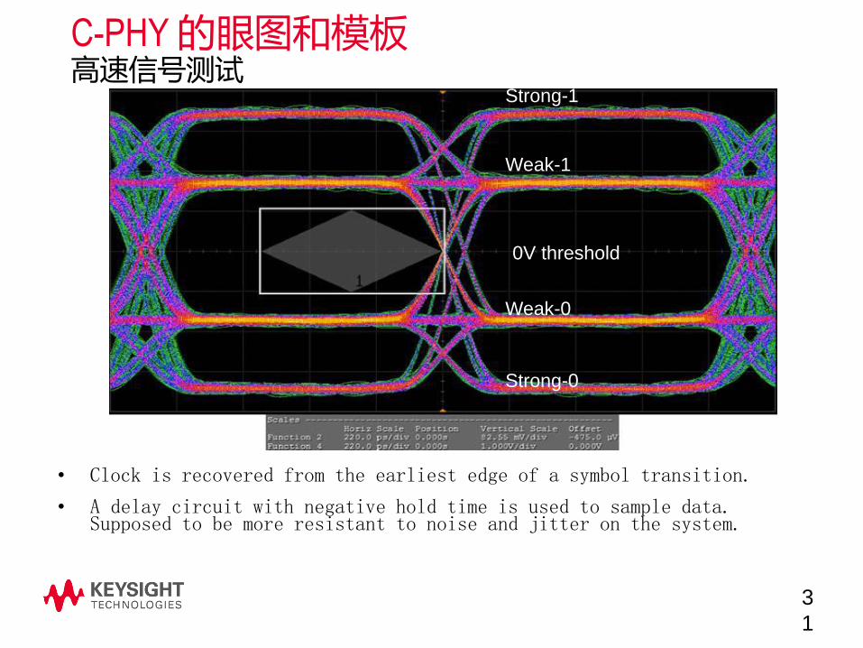
C-PHY 的眼图和模板高速信号测试
3
1
• Clock is recovered from the earliest edge of a symbol transition.
• A delay circuit with negative hold time is used to sample data. Supposed to be more resistant to noise and jitter on the system.
Strong-1
Weak-1
Weak-0
Strong-0
0V threshold
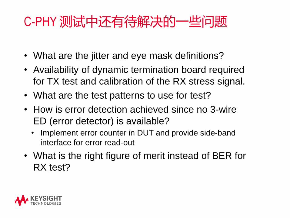
C-PHY 测试中还有待解决的一些问题
• What are the jitter and eye mask definitions?
• Availability of dynamic termination board required
for TX test and calibration of the RX stress signal.
• What are the test patterns to use for test?
• How is error detection achieved since no 3-wire
ED (error detector) is available?• Implement error counter in DUT and provide side-band
interface for error read-out
• What is the right figure of merit instead of BER for
RX test?

内容安排
MIPI 物理层的发展
MIPI 物理层的电气特点
物理层测试的挑战以及测试方案
• 发送端的测试
• 接收端的测试
• 回波损耗的测试
总结
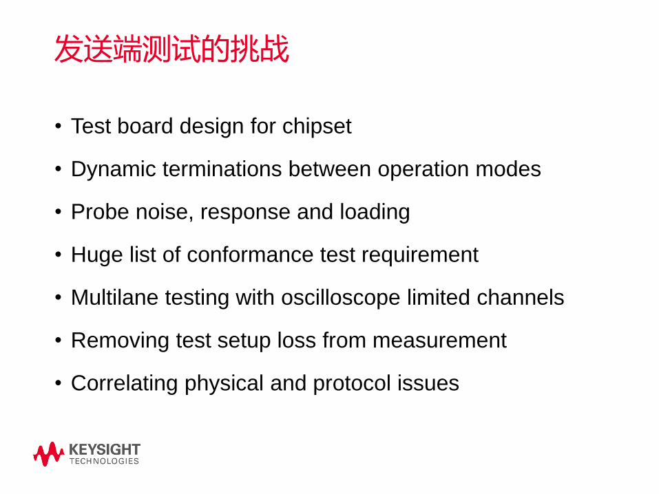
发送端测试的挑战
• Test board design for chipset
• Dynamic terminations between operation modes
• Probe noise, response and loading
• Huge list of conformance test requirement
• Multilane testing with oscilloscope limited channels
• Removing test setup loss from measurement
• Correlating physical and protocol issues

适用于芯片、模组测试的测试板Test Vehicle Board (TVB)
Page
35
https://members.mipi.org/mipi-
testing/workspace/StartPage
PHY
Chip
TVB

不同工作模式下的动态端接Reference Termination Board (RTB)
Reference Termination Board
(RTB) terminates the signals
dynamically according to the
operation termination
requirement.
D-PHY and C-PHY RTB, as well
as fixed M-PHY load board are
available.
https://www.iol.unh.edu/services/
testing/mipi/fixtures.php
PHY
Chip
TVB
RTB
SMA
Probe

探头的噪声、频响和负载影响
P
a
g
• Probes with low noise and loading (as low as 70 fF) are available.
• S-parameter stored in the probe amplifier.
• PrecisionProbe can be used for AC calibration.
• Flexible probe accessories:
o Solder-in probe head
o ZIF probe and tips
o Socket head
o Browser
o 2.92mm/SMA head
Example 25 GHz ZIF probe and tip
InfiniiMax Probes
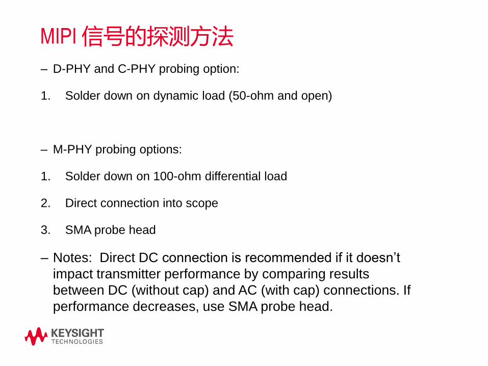
MIPI 信号的探测方法
– D-PHY and C-PHY probing option:
1. Solder down on dynamic load (50-ohm and open)
– M-PHY probing options:
1. Solder down on 100-ohm differential load
2. Direct connection into scope
3. SMA probe head
– Notes: Direct DC connection is recommended if it doesn’t
impact transmitter performance by comparing results
between DC (without cap) and AC (with cap) connections. If
performance decreases, use SMA probe head.
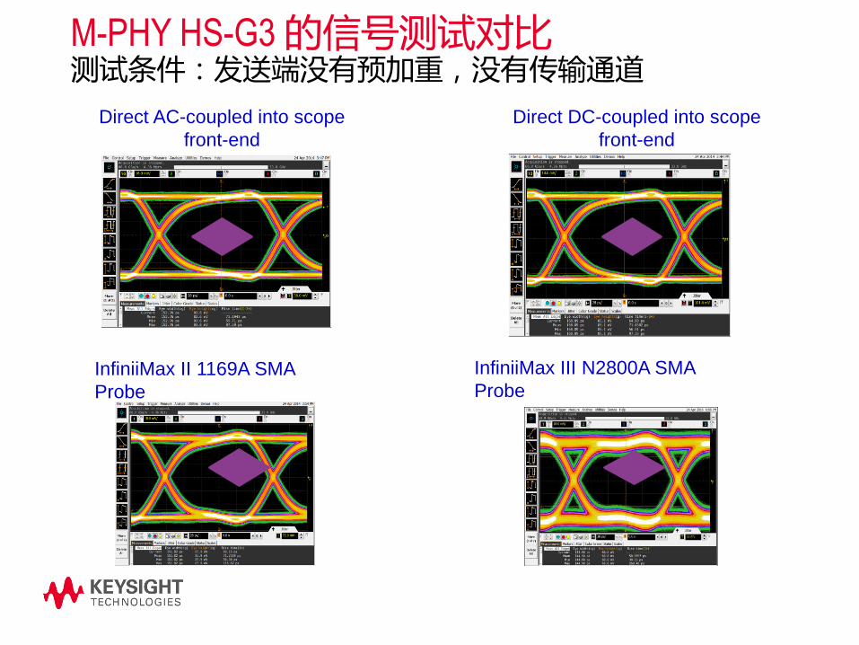
M-PHY HS-G3 的信号测试对比测试条件:发送端没有预加重,没有传输通道
Direct AC-coupled into scope
front-end
Direct DC-coupled into scope
front-end
InfiniiMax II 1169A SMA
Probe
InfiniiMax III N2800A SMA
Probe

M-PHY HS-G3 的信号测试对比测试条件:发送端没有预加重,经过CH1参考通道
InfiniiMax III N2800A SMA Probe
Direct AC-coupled into scope
front-end
Direct DC-coupled into scope
front-end
InfiniiMax II 1169A SMA Probe

大量的一致性测试项目Signal Group Test Parameters
High-Speed Clock
Electrical Transmitter
Characteristics
Static Common Mode Voltage (Vcmtx)
Vcmtx Mismatch
Differential Voltage (VOD)
Differential Voltage Mismatch
Single-Ended Output High Voltage (VOHHS)
Common-Level Variations Above 450MHz (VCMTX(HF))
Common-Level Variations Between 50-450MHz (VCMTX(LF))
20%-80% Rise Time (tR)
20%-80% Fall Time (tF)
High-Speed Data
Electrical Transmitter
Characteristics
Static Common Mode Voltage (Vcmtx)
Vcmtx Mismatch
Differential Voltage (VOD)
Differential Voltage Mismatch
Single-Ended Output High Voltage (VOHHS)
Common-Level Variations Above 450MHz (VCMTX(HF))
Common-Level Variations Between 50-450MHz (VCMTX(LF))
20%-80% Rise Time (tR)
20%-80% Fall Time (tF)
Signal Group Test Parameters
LP TX Electrical
Characteristics
Thevenin Output High Voltage Level (VOH)
Thevenin Output Low Voltage Level (VOL)
30%-85% Post-EoT Rise Time (TREOT)
15%-85% Fall Time (TFLP)
15%-85% Rise Time (TRLP)
Pulse Width of LP TX Exclusive-OR Clock (TLP-PULSE-TX)
Period of L TX Exclusive-OR Clock (TLP-PER-TX)
Slew Rate Vs. CLoad
Global Operation for
Data Signals
TLPX
LP Exit: DATA TX THS-PREPARE
LP Exit: DATA TX THS-PREPARE+THS-ZERO
HS Exit: DATA TX THS-TRAIL
HS Exit: DATA TX TEOT
HS Exit: DATA TX THS-EXIT
Global Operation for
Clock
LP Exit: CLK TX THS-EXIT
LP Exit: CLK TX TLPX
LP Exit: CLK TX TCLK-PREPARE
LP Exit: CLK TX TCLK-PREPARE+TCLK-ZERO
LP Exit: CLK TX TCLK-TRAIL
HS Exit: LK TX TEOT
HS Data-Clock Timing
HS Clock Instantaneous (UIinst)
HS Clock Rising Edge Alignments to First Payload Bit
Data-to-Clock Skew (TSKEW(TX))
HS Clock
PHY
HS Data
PHY
LP Clock /
Data PHY
LP-HS Data
Timing
LP-HS Clock
Timing
HS Clock-
Data Timing
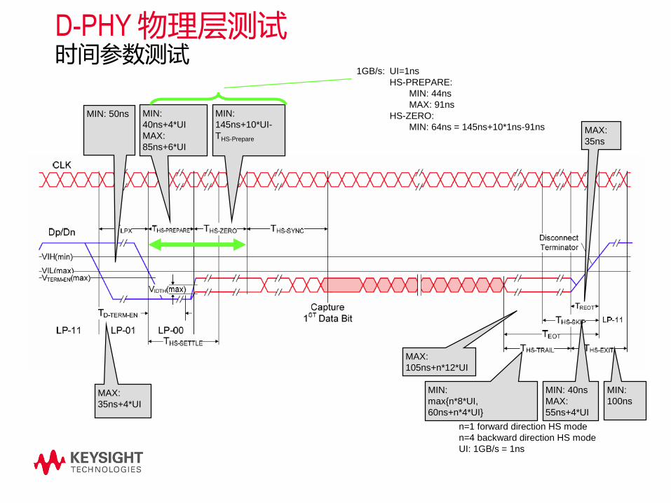
D-PHY 物理层测试时间参数测试
MIN: 50ns
MAX:
35ns+4*UI
MIN: 40ns
MAX:
55ns+4*UI
MIN:
max{n*8*UI,
60ns+n*4*UI}
MIN:
100ns
MAX:
105ns+n*12*UI
n=1 forward direction HS mode
n=4 backward direction HS mode
UI: 1GB/s = 1ns
MIN:
40ns+4*UI
MAX:
85ns+6*UI
MIN:
145ns+10*UI-
THS-Prepare
MAX:
35ns
1GB/s: UI=1ns
HS-PREPARE:
MIN: 44ns
MAX: 91ns
HS-ZERO:
MIN: 64ns = 145ns+10*1ns-91ns

M-PHY CTS v3.0r14 要求的高速信号的测试项目
HS-TX TestsHS-G1 HS-G2 HS-G3 Burst
Continuo
us LA SA RT NT
1.1.1 f_OFFSET Yes Yes Yes Yes Yes Yes No Yes No
1.1.2 PSDCM Info No No Yes No Yes Yes Yes No
1.1.3 PREPARE_Length Yes Yes Yes Yes No Yes Yes Yes No
1.1.4 VCM Yes Yes Yes Yes No Yes Yes Yes No
1.1.5 VDIF_DC Yes Yes Yes Yes No Yes Yes Yes No
1.1.6 G1/G2 TEYE_TX,
VDIF_AC Yes Yes No Yes Yes Yes Yes Yes No
1.1.7 G3 TEYE_TX, VDIF_AC No No Yes Yes Yes Yes Yes Yes No
1.1.8 TR_TF_HS Yes Yes Yes Yes No Yes Yes Yes No
1.1.9 L2L_SKEW Yes Yes Yes Yes No Yes No Yes No
1.1.10 SR_DIF[MAX] Yes No No Yes No Yes Yes Yes No
1.1.10 SR_DIF[MIN] Yes No No Yes No Yes Yes Yes No
1.1.11 SR_DIF
Monotonicity Yes No No Yes No Yes Yes Yes No
1.1.12 ∆SR_DIF Resolution Yes No No Yes No Yes Yes Yes No
1.1.13 TINTRA_SKEW Yes Yes Yes Yes Optional Yes Yes Yes No
1.1.14 TPULSE Yes Yes Yes Yes No Yes Yes Yes No
1.1.15 TJ Yes Yes Yes No Yes Yes Yes Yes No
1.1.16 STTJ Yes Yes Yes Info Yes Yes Yes Yes No
1.1.17 DJ Yes Yes Yes No Yes Yes Yes Yes No
1.1.18 STDJ Yes Yes Yes Info Yes Yes Yes Yes No

M-PHY 眼图和抖动的测试
• No de-emphasis in G1 and G2. G3 requires de-emphasis.
• Nominal 3.5dB de-emphasis for LA and SA swing
• Nominal 6dB de-emphasis for LA swing
• G4 requires CTLE and one-tap DFE at receiver.
• Different BER 1E-10 eye mask definition for G1, G2 and G3.
• G4 leverages G3 reference channels and also to include reference package model.
• TJ, DJ, STTJ and STDJ are normative with continuous signal. DJ and STDJ are informative with burst using TIEpp method.
G1 – 0.2UI opening between 0.4-0.9UI
No channel0.2UI eye opening at 0.5UI
No channel
Diamond mask at 0.5UI
Embed CH1 – SA and CH2 – LA swing

C-PHY 物理层的测试大量的时间参数测试– –来源于D-PHY但又不太一样

• Rise/fall time measured between -58mV to 58mV thresholds on S-W transitions. W-
W transitions are slowest, but S-W are critical to eye-opening.
• Eye mask defined at the receiver.
• Embed 6-port model – IL/RL and CTLE, as well as Xtalk from adjacent channels.
• Jitter still undefined.
• Common point replaces common mode test.
C-PHY 上升/下降时间、眼图和抖动的测试

自动的信号一致性测试软件
Configure the
Device Under Test
Select Tests.
Automatically generate
test report.
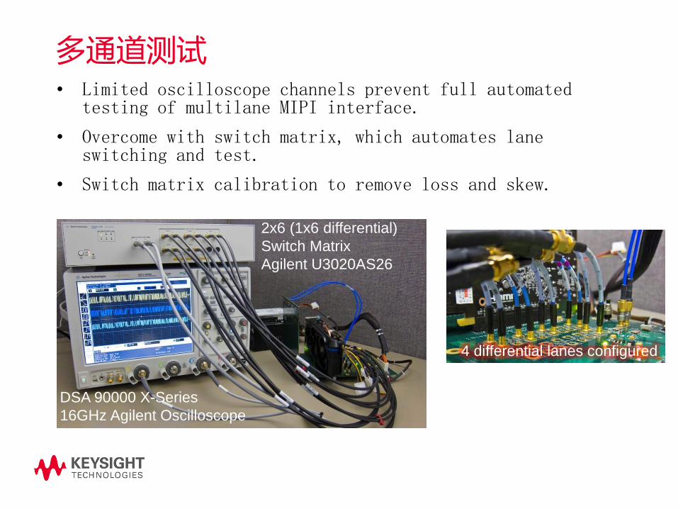
多通道测试• Limited oscilloscope channels prevent full automated
testing of multilane MIPI interface.
• Overcome with switch matrix, which automates lane switching and test.
• Switch matrix calibration to remove loss and skew.
DSA 90000 X-Series
16GHz Agilent Oscilloscope
2x6 (1x6 differential)
Switch Matrix
Agilent U3020AS26
4 differential lanes configured

消除测试电缆、探头损耗带来的影响
Computed insertion loss
gain function based on
measured S21 (Yellow)
Original signal
frequency
content (green)
Frequency content with
loss compensation
applied (Blue)
使用示波器和矢网的去嵌入功能(InfiniiSim) 或者示波器的TDT修正功能(PrecisionProbe)

物理层和协议层的联合调试在示波器里进行MIPI的协议解码 (举例: UFS / UniPro)
Simultaneous
show UFS and
UniPro packet
decode on
analog
waveform.
Move back and
forth between
UFS and UniPro
packets
Shows
whether the
bits are
correctly
received with
the CRC
verification.
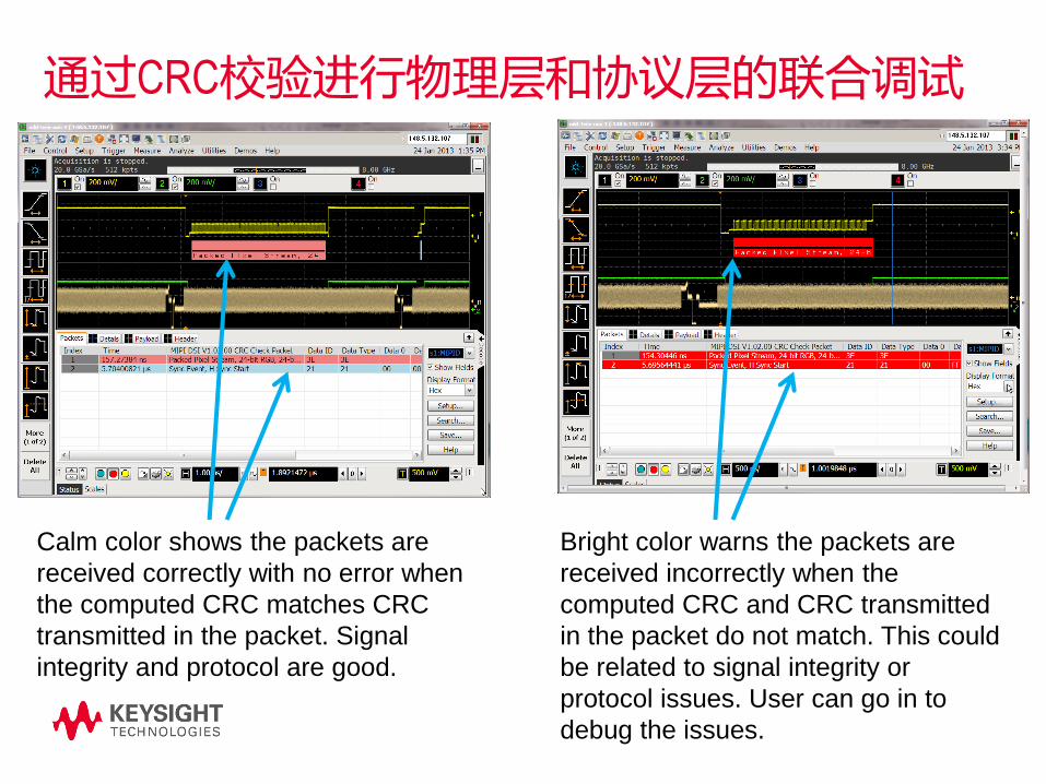
通过CRC校验进行物理层和协议层的联合调试
Calm color shows the packets are
received correctly with no error when
the computed CRC matches CRC
transmitted in the packet. Signal
integrity and protocol are good.
Bright color warns the packets are
received incorrectly when the
computed CRC and CRC transmitted
in the packet do not match. This could
be related to signal integrity or
protocol issues. User can go in to
debug the issues.

测试主题的内容安排
MIPI 物理层的发展
MIPI 物理层的电气特点
物理层测试的挑战以及测试方案
• 发送端的测试
• 接收端的测试
• 回波损耗的测试
总结

接收端的测试
Stressed Signal Generator
RJDJISI
Rx
ChipTx
Loop BackRJRJ+DJRJ+DJ+ISI
Error Detector
Stressed Signal
Jitter Cocktail
ISI

接收端测试的挑战
• Receiver stress signal generation
- Various timing requirements
- Complex jitter cocktail
• Programming designs into test modes
- No standardization in the PHY spec
- Method varies by the protocol
• Error detection with different protocols
- No standardization
- Specific method defined in protocol spec, not in PHY
spec
- Not mandatory (optional normative / recommendation)
- Asymmetrical lane configuration
Custom
Test Board
TP
ISI Conformance Channel
BERT
Pattern
Generator
w/ TTCs
Breakout Trace
ASICRX
DUT
TX
Ref
Clk
Inte
rnal Loopback
or
Err
or
counte
r
Replica
Trace
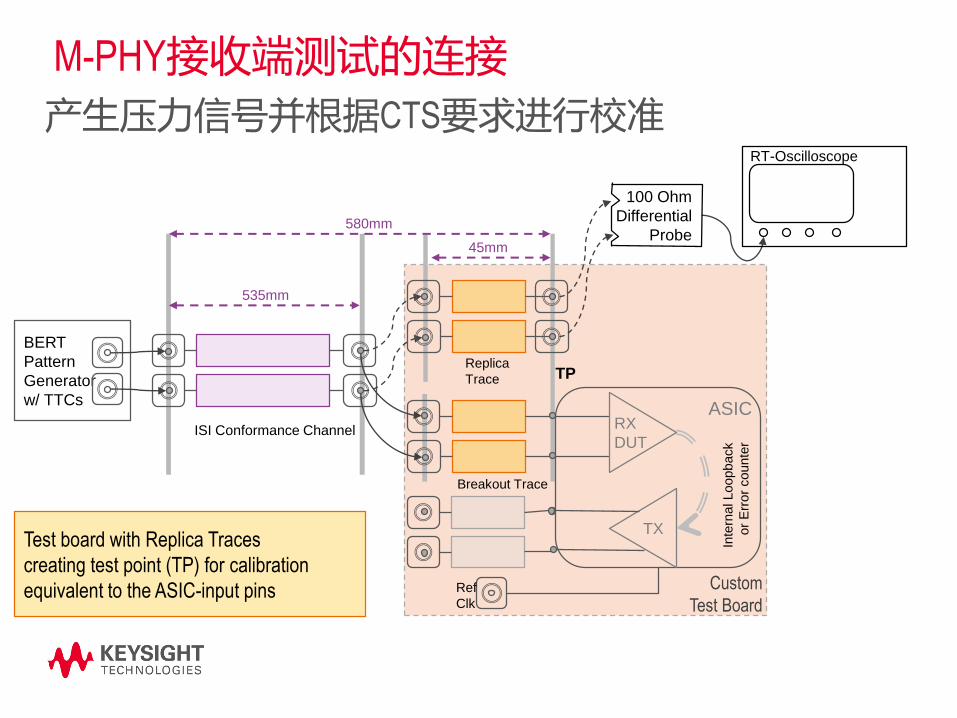
M-PHY接收端测试的连接
产生压力信号并根据CTS要求进行校准
535mm
580mm
45mm
100 Ohm
Differential
Probe
RT-Oscilloscope
Test board with Replica Traces
creating test point (TP) for calibration
equivalent to the ASIC-input pins

使用M8020A进行M-PHY接收端测试的连接
• 1:1 match of CTS proposed set-up with actual Agilent J-BERT set-up
• ISI conformance channel relaized through N4915 60001 SATA ISI trace (2)
RT-Oscilloscope
J-BERT M8020A
100 Ohm
Differential
Probe
Err
Ctr
M-
RX
M-TX
loopback
N4915-60001

D-PHY 接收端测试的典型配置需要通过合路的方式同时产生HS和LP的信号
DUT
举例:支持1对时钟线和2对数据线的基于81250的配置

产生D-PHY的压力信号的例子

C-PHY接收测试设置 (One Trio)
• Two M8190A AWG modules + one M8192A sync module is
needed to drive the four signals
• M8190A AWG is flexible enough to support C-PHY
waveforms without external circuitry
A
B
C
D
A B
C D
Only 3 of 4 available channels needed
to drive a C-PHX lane
4th channel available for any aux signal

1Gsym/s的C-PHY信号-LP和HS状态的切换
• Sequence of low power and hi speed signal • separated (offset-shifted, left) and overlaid (same
offset, right)

众多的的接收容限测试项目CTS chapter Title AT
HS-
mode
2.1.1 HS-RX Differential DC Input Voltage Amplitude Tolerance
2.1.2 HS-RX Accumulated Differential Input Voltage Tolerance
2.1.3 HS-RX Common Mode Input Voltage Tolerance
2.1.4 HS-RX Differential Termination Enable Time
2.1.5 HS-RX Differential Termination Disable Time
2.1.6 HS-RX Lane-to-Lane Skew (TL2L-SKEW-HS-RX) -
2.1.7 HS-RX Receiver Jitter Tolerance
2.1.8 HS-RX Frequency Offset Tolerance
2.1.9 HS-RX PREPARE Length Capability Verification
2.1.10 HS-RX Sync Length Capability Verification
LS-
mode
(PWM)
2.2.1 PWM-RX Differential DC Input Voltage Amplitude Tolerance
2.2.2 PWM-RX Accumulated Differential Input Voltage Tolerance
2.2.3 PWM-RX Common Mode Input Voltage Tolerance
2.2.4 PWM-RX Differential Termination Enable Time
2.2.5 PWM-RX Differential Termination Disable Time
2.2.6 PWM-RX Lane-to-Lane Skew (TL2L-SKEW-PWM-RX) -
2.2.7 PWM-RX Receive Bit Duration Tolerance
2.2.8 PWM-RX Receive Ratio, PWM-G1 and Above
2.2.9 PWM-RX Receive Minor Duration in PWM-G0 -
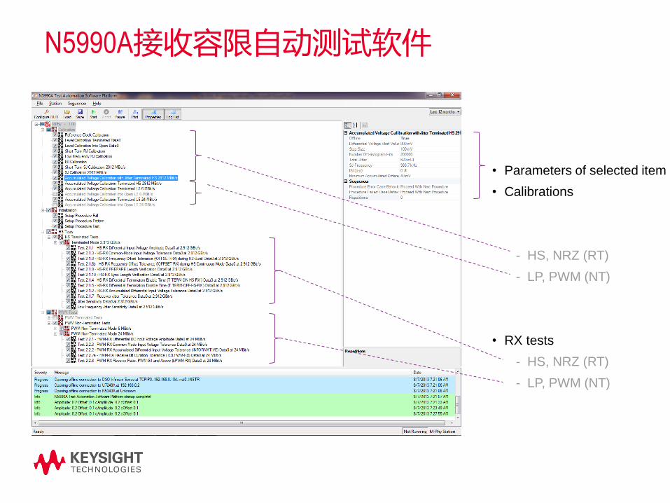
• Parameters of selected item
• Calibrations
- HS, NRZ (RT)
- LP, PWM (NT)
• RX tests
- HS, NRZ (RT)
- LP, PWM (NT)
N5990A接收容限自动测试软件
M-PHY
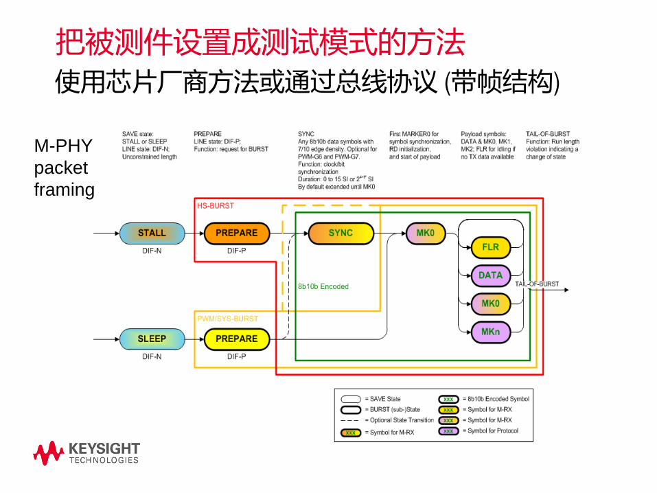
packet
framing
把被测件设置成测试模式的方法
Page
63
使用芯片厂商方法或通过总线协议 (带帧结构)

M-PHY 的数据帧生成软件
支持81250并行误码仪和N4903B串行误码仪
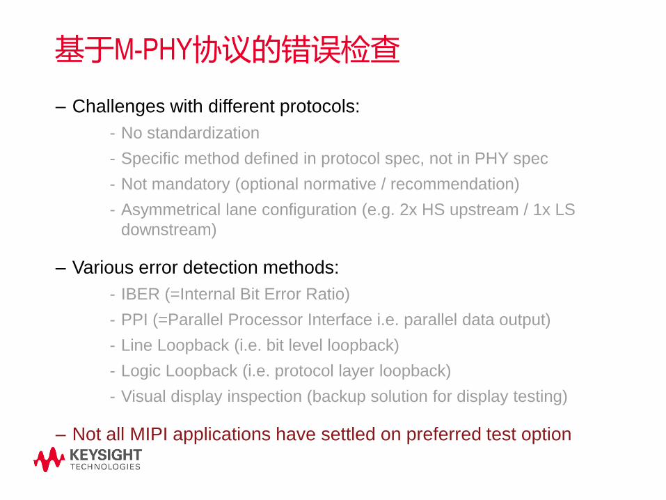
基于M-PHY协议的错误检查
– Challenges with different protocols:
- No standardization
- Specific method defined in protocol spec, not in PHY spec
- Not mandatory (optional normative / recommendation)
- Asymmetrical lane configuration (e.g. 2x HS upstream / 1x LS
downstream)
– Various error detection methods:
- IBER (=Internal Bit Error Ratio)
- PPI (=Parallel Processor Interface i.e. parallel data output)
- Line Loopback (i.e. bit level loopback)
- Logic Loopback (i.e. protocol layer loopback)
- Visual display inspection (backup solution for display testing)
– Not all MIPI applications have settled on preferred test option

no
错误检查方法的选择• Use BERT ED for bit comparison and error counting when loopback is implemented
• Use BERT ED (for capture, upload, postprocess) or Oscillospe (w/ serial decode)
- For reading counters provided by protocol
- When testmode with built in TPV is provided
• Use external PC to read customer provided IBERReader DLL with counter results
How can
error
counting be
realized?
yes
Loop-
back Mode
supported?
Connect BERT ED
for error counting
Use IBERReader
DLL to
communicate to
computer
Error
counter (TPV)
implemented
?
Result
transmitted
via TX ?
yes
no
Connect BERT-ED
for capture, upload
& post-processing
(LLI)
Read protocol’s
Packet- and
ErrorPacket-
Counter’s (UniPro)
yesno
Loopback is not always possible
• not all MIPI links are symmetrical, i.e. mode and gear settings for the involved M-RX and M-TX are not commonly supported.
• applications (protocols) residing on M-PHY optimize their support for testing and therefore mandatory requirements for testing may not include a support for loopback mode
Getting results of internal TPV
• either through a (low speed) M_TX
• or IBERReader DLL or (proprietary) programming interface of the DUT

不同应用中进行M-PHY接收端测试的方法
DigRF 4 UniPro LLI SSIC
Test
configuration
Single lane and multi
lane test possible
In a multi-lane
configuration all lanes
must be tested
simultaneously
Test one lane at a time Test one lane at a time
DUT
Error Detection
Method
Loopback, options:
• BERT error detector
can only be used if
there is no re-timing
• DigRF 4 Exerciser
• Custom method,
either internal error
counter (IBER) or
golden receiver
Internal error counter
(IBER): oscilloscope to
capture counter
readings
Internal error counter
(IBER): oscilloscope to
capture counter
readings
Internal error counter (IBER) and
Loopback (both needed for full
test coverage)
The internal error counter can be
read either with BERT error
detector or with oscilloscope
Loopback requires
J-BERT B SER mode
Instrument
recommendatio
n
ParBERT,
J-BERT B (1 or 2
lanes)
ParBERT,
J-BERT B (1 or 2
lanes)
ParBERT,
J-BERT B
J-BERT B
Err
Ctr
M-
RX
M-TX
loopback
Err
Ctr
M-
RX
M-TXErr
Ctr
M-
RX
M-TX
M-
RX
M-TX
loopback

C-PHY接收端测试方法的进展
• Signal calibration still to be determined.
• Error counting always done with internal counter
• No loopback mode
• No need to have a C-PHY conformant ED
• No CTS available yet (work has not yet started)
• No automation SW available yet

测试主题的内容安排
MIPI 物理层的发展
MIPI 物理层的电气特点
物理层测试的挑战以及测试方案
• 发送端的测试
• 接收端的测试
• 回波损耗的测试
总结

Transmitter Impedance MatchedTransmitter Impedance NOT Matched
Transmitter Termination Effects
回波损耗对信号的影响A portion of the transmitted signal is reflected due to impedance mismatches. If the
signal path is not impedance matched, reflections can cause eye closure.
t
Tx Rx

S参数测和阻抗、回波损耗测试发送和接收设备的回波损耗要在上电状态下测试
t
t
The TX is required to transmit a repetitive pattern
when characterizing its return loss.
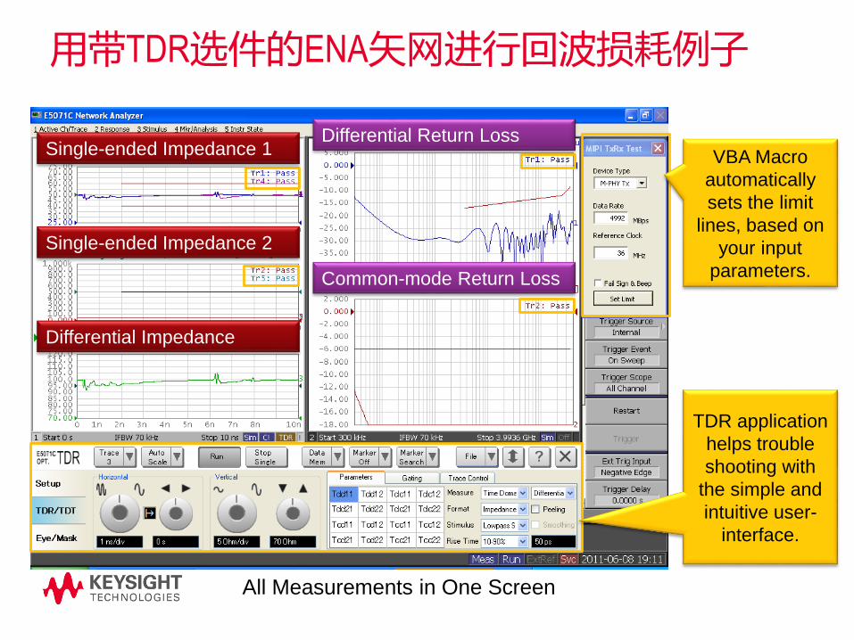
用带TDR选件的ENA矢网进行回波损耗例子
TDR application
helps trouble
shooting with
the simple and
intuitive user-
interface.
VBA Macro
automatically
sets the limit
lines, based on
your input
parameters.
All Measurements in One Screen
Single-ended Impedance 1
Single-ended Impedance 2
Differential Impedance
Differential Return Loss
Common-mode Return Loss
测试主题的内容安排
MIPI 物理层的发展
MIPI 物理层的电气特点
物理层测试的挑战以及测试方案
• 发送端的测试
• 接收端的测试
• 回波损耗的测试
总结

Keysight公司MIPI测试的整体解决方案Transmitter
Characterization
DSAQ93204A Infiniium
U7238B D-PHY, U7249B
M-PHY, N5467B C-PHY UDA
InfiniiMax Probes
Switch matrix
N5465A InfiniiSim
N2809A PrecisionProbe
Receiver
Characterization
N4903B/M8020A JBERT
M8190 AWG
81250A ParBERT
N5990A Automated characterization
Impedance/Return Loss
Validation
E5071C ENA Option TDR
DCA 86100D Wideband sampling
oscilloscope
N1055A
TDR/TDT
54754A
TDR/TDT
Industry’s highest analog
bandwidth, lowest noise
floor/sensitivity, jitter measurement
floor with unique cable/probe
correction
Precision impedance
measurements and
S-Parameter capability
Highest precision jitter lab source
with automated compliance
software for accurate, efficient, and
consistent measurement
Protocol Stimulus and
Analysis
U4421A D-PHY CSI-2 / DSI
Analyzer and Exerciser
U4431A M-PHY Analyzer (UFS,
UniPro, CSI-3, SSIC, M-PCIe)
Scope Protocol DecoderN8802A CSI-2 / DSI
N8807A DigRF v4
N8808A UniPro
N8818A UFS
N8809A LLI
N8819A SSIC
N8820A CSI-3
N8824A RFFE
Fast upload and display, accurate
capture, intuitive GUI and
customizable hardware. Correlate
physical and protocol layer.

总结
• Mobile applications are driving the needs for higher
performance and lower power usage.
• D-PHY is widely adopted. D-PHY extension and C-PHY
are added to increase performance.
• M-PHY will be widely adopted by different applications,
including standards outside of the MIPI ecosystem.
• Keysight is driving specification and testing dicussions
within MIPI workgroups and the test houses, as well as
other key standard ecosystems.
参考资料
– MIPI total solution page
• www.agilent.com/find/mipi
– Application note:
• How to Test a MIPI M-PHY High-Speed Receiver
• Using Microwave Switches When Testing High
Speed Serial Digital Interfaces
– Method of Implementation:
• D-PHY Return Loss / Cable ENA measurements
• M-PHY Return Loss / Cable ENA measurements
– Published white paper at Microwave Journals:
• Multilane MIPI Testing with MW Switches
– Switch calibration and correction application
notes:
• S-parameter Requirements for Oscilloscope
De-embedding
• PrecisionProbe for Bandwidths up to 33 GHz
– Integrated switch matrix hardware:
• Agilent U3020AS26
• BitifEye 2100 Series

谢谢参加!