mitsubishi industrial robot melfa f series … industrial robot f series mitsubishi industrial robot...
TRANSCRIPT

MITSUBISHI INDUSTRIAL ROBOT
F Series
MITSUBISHI INDUSTRIAL ROBOT
F Series
This catalog is an introduction to only part of what Mitsubishi Electric has to offer.
Mitsubishi Electric offers individualized solutions for the challenges in your factory.
HEAD OFFICE: TOKYO BUILDING, 2-7-3, MARUNOUCHI, CHIYODA-KU, TOKYO 100-8310, JAPANNAGOYA WORKS: 1-14, YADA-MINAMI 5, HIGASHI-KU, NAGOYA, JAPAN
L(NA)-09067ENG-C
New publication, effective Jul. 2013
Specifications are subject to change without notice.
Mitsubishi Electric Automation Korea Co., Ltd.1480-6, Gayang-Dong, Gangseo-Gu Seoul 157-200, Korea
Mitsubishi Electric Asia Pte, Ltd.307 Alexandra Road #05-01/02, Mitsubishi Electric Building, Singapore
Mitsubishi Electric Automation (Thailanad) Co., Ltd. Bang-Chan Industrial Estate No.111 Soi Serithai 54, T.Kannayao, A.Kannayao, Bangkok 10230 Thailand
Korea
Singapore
Thailand
Tel: +82-2-3660-9552Fax: +82-2-3664-8372
Tel: +65-6470-2480Fax: +65-6476-7439
Tel: +66-2517-1326Fax: +66-2906-3239
China
Mitsubishi Electric Taiwan Co.,Ltd.10F,No.88,Sec.6,Chung-Shan N.Rd.,Taipei,Taiwan
Taiwan Tel: +886-02-2833-5430Fax: +886-02-2833-5433
Mitsubishi Electric Automation (CHINA) Ltd.No.1386 Hongqiao Road, Mitsubishi Electric Automation Center 3F Shanghai,
China
Russia
Tel: +86-21-2322-3030Fax: +86-21-2322-3000
Mitsubishi Electric Europe B.V. Russian Branch Moscow Office52, bld. 3, Kosmodamianskaya nab., RU-115054, Moscow, Russia
Tel: +7-495-721-2070Fax: +7-495-721-2071
Sales OfficeCountry/Region Tel/Fax
Mitsubishi Electric Automation lnc.500 Corporate Woods Parkway Vernon Hills, IL 60061, USA
MITSUBISHI ELECTRIC DO BRASIL COMERCIO E SERVICOS LTDA.Rua Jussara, 1750 - Bloco B- Sala 01, Jardim Santa Cecilia - CEP 06465-070,Barueri - SP, Brasil
Mitsubishi Electric Europe B.V. German BranchGothaer Strasse 8 D-40880 Ratingen, Gernany
Mitsubishi Electric Europe B.V. UK BranchTravellers Lane, Hatfield, Hertfordshire., AL10 8XB, UK
Mitsubishi Electric Europe B.V. Italian BranchVIALE COLLEONI 7-20041 Agrate Brianza(Milano),Italy
Mitsubishi Electric Europe B.V. Spanish BranchCarretera de Rubi 76-80-AC.420,E-08190 Sant Cugat del Valles(Barcelona), Spain
Mitsubishi Electric Europe B.V. French Branch25,Boulevard des Bouvets, F-92741 Nanterre Cedex, France
Mitsubishi Electric Europe B.V. Czech BranchAvenir Business Park, Radicka 714/113a, 158 00 Praha5, Czech Republic
Mitsubishi Electric Europe B.V. Polish Branchul. Krakowska 50 32-083 Balice, Poland
U.S.A
Brazil
Germany
U.K
Italy
Spain
France
Czech Republic
Poland
Tel: +1-847-478-2100Fax: +1-847-478-2253
Tel: +55-11-4689-3000Fax: +55-11-4689-3016
Tel: +49-2102-486-0Fax: +49-2102-486-1120
Tel: +44-1707-27-6100Fax: +44-1707-27-8695
Tel: +39-039-60531Fax: +39-039-6053-312
Tel: +34-935-65-3131Fax: +34-935-89-2948
Tel: +33-1-5568-5568Fax: +33-1-5568-5757
Ireland
Tel: +420-251-551-470Fax: +420-251-551-471
Tel: +48-12-630-47-00Fax: +48-12-630-47-01
Mitsubishi Electric Europe B.V. Irish BranchWestgate Business Park, Ballymount. IRL-Dublin 24
Tel: +353-14198800Fax: +353-14198890
Mitsubishi Electric India Pvt. Ltd. Emerald House, EL-3, J Block, M.I.D.C., Bhosari, Pune, 411026,Maharashtra State, India
India Tel: +91-2710-2000Fax: +91-2710-2100
1 2
Pro
duct
Lin
eup
Robot
Specific
ations
Fu
nctio
ns
Options
Syste
m C
on
fig
ura
tio
nC
onfigura
tions O
ptio
ns
Co
ntr
olle
r S
pecific
ations
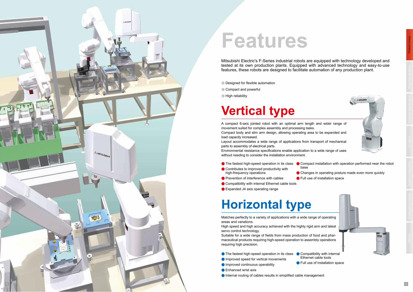
Vertical type
The fastest high-speed operation in its class
Contributes to improved productivity with high-frequency operations
Prevention of interference with cables
A compact 6-axis jointed robot with an optimal arm length and wider range of
movement suited for complex assembly and processing tasks.
Compact body and slim arm design, allowing operating area to be expanded and
load capacity increased.
Layout accommodates a wide range of applications from transport of mechanical
parts to assembly of electrical parts.
Environmental resistance specifications enable application to a wide range of uses
without needing to consider the installation environment.
Horizontal type
The fastest high-speed operation in its class
Improved speed for vertical movements
Compatibility with internal Ethernet cable tools
Full use of installation space
Matches perfectly to a variety of applications with a wide range of operating
areas and variations.
High speed and high accuracy achieved with the highly rigid arm and latest
servo control technology.
Suitable for a wide range of fields from mass production of food and phar-
maceutical products requiring high-speed operation to assembly operations
requiring high precision.
Features
Designed for flexible automation
Compact and powerful
High reliability
Mitsubishi Electric's F-Series industrial robots are equipped with technology developed and tested at its own production plants. Equipped with advanced technology and easy-to-use features, these robots are designed to facilitate automation of any production plant.
Compatibility with internal Ethernet cable tools
Expanded J4 axis operating range
Compact installation with operation performed near the robot base
Changes in operating posture made even more quickly
Full use of installation space
Improved continuous operability
Enhanced wrist axis
Internal routing of cables results in simplified cable management
3 4
Pro
duct
Lin
eup
Robot
Specific
ations
Fu
nctio
ns
Options
Syste
m C
on
fig
ura
tio
nC
onfigura
tions O
ptio
ns
Co
ntr
olle
r S
pecific
ations
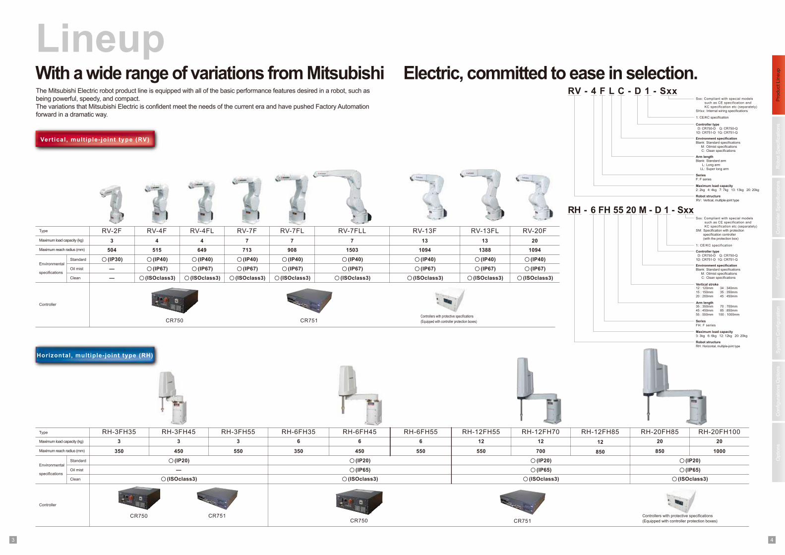
With a wide range of variations from Mitsubishi Electric, committed to ease in selection.
Lineup
Vertical, mult iple-joint type (RV)
Horizontal, multiple-joint type (RH)
The Mitsubishi Electric robot product line is equipped with all of the basic performance features desired in a robot, such as
being powerful, speedy, and compact.
The variations that Mitsubishi Electric is confident meet the needs of the current era and have pushed Factory Automation
forward in a dramatic way.
RH-3FH45
450
○(IP20)
—
RH-3FH55
550
RH-6FH35
350
RH-6FH45
450
○(IP20)
○(IP65)
RH-6FH55
550
RH-12FH55
550
RH-12FH70
700
○(IP20)
○(IP65)
RH-12FH85
1000
○(IP20)
○(IP65)
RH-3FH35
350
RV-4FType
Environmental
specifications
Maximum load capacity (kg)
Maximum reach radius (mm) 504
○(IP30)
—
RV-4FL
515
RV-7F
649
RV-7FL
713 908
Controller
RV-2F
Controllers with protective specifications
(Equipped with controller protection boxes)
RV - 4 F L C - D 1 - SxxSxx: Compliant with special models
such as CE specification and
KC specification etc (separately)
SHxx: Internal wiring specifications
Environment specification
Blank: Standard specifications
M : Oilmist specifications
C : Clean specifications
Controller type
D: CR750-D Q: CR750-Q
1D : CR751-D 1Q: CR751-Q
Arm length
Blank: Standard arm
L : Long arm
LL : Super long arm
Series
F: F series
Maximum load capacity
2 : 2kg 4: 4kg 7: 7kg 13: 13kg 20: 20kg
Robot structure
RV : Vertical, multiple-joint type
Maximum load capacity
3: 3kg 6: 6kg 12: 12kg 20: 20kg
Robot structure
RH: Horizontal, multiple-joint type
RH - 6 FH 55 20 M - D 1 - SxxSxx: Compliant with special models
such as CE specification and
KC specification etc (separately)
SM : Specification with protection
specification controller
(with the protection box)
Environment specification
Blank: Standard specifications
M : Oilmist specifications
C : Clean specifications
Controller type
D: CR750-D Q: CR750-Q
1D : CR751-D 1Q: CR751-Q
Vertical stroke12 : 120mm
15 : 150mm
20 : 200mm
34 : 340mm
35 : 350mm
45 : 450mm
35 : 350mm
45 : 450mm
55 : 550mm
70 : 700mm
85 : 850mm
100 : 1000mm
Arm length
Series
FH: F series
Standard
Oil mist
Clean
3 4 4 7 7
— ○(ISOclass3) ○(ISOclass3) ○(ISOclass3) ○(ISOclass3)
○(IP40)
○(IP67)
○(IP40)
○(IP67)
○(IP40)
○(IP67)
○(IP40)
○(IP67)
Maximum load capacity (kg)
Maximum reach radius (mm)
Standard
Oil mist
Clean
Controller
Type RH-20FH85 RH-20FH100
850850
3 3 6 6 6 12 12 203 2012
○(ISOclass3)○(ISOclass3) ○(ISOclass3) ○(ISOclass3)
Controllers with protective specifications
(Equipped with controller protection boxes)
Environmental
specifications
CR750 CR751
CR750 CR751CR751CR750
1: CE/KC specification
1: CE/KC specification
RV-7FLL
1503
7
○(ISOclass3)
○(IP40)
○(IP67)
RV-13F
1094
13
○(ISOclass3)
○(IP40)
○(IP67)
RV-13FL
1388
13
○(ISOclass3)
○(IP40)
○(IP67)
RV-20F
1094
20
○(ISOclass3)
○(IP40)
○(IP67)
1 25 6
Pro
duct
Lin
eup
Robot
Specific
ations
Fu
nctio
ns
Options
Syste
m C
on
fig
ura
tio
nC
onfigura
tions O
ptio
ns
Co
ntr
olle
r S
pecific
ations
Specifications
Structure
J3
J4
J5
Cycle time *4
Maximum speed
Position repeatability
Ambient temperature
Machine cable
Connected controller
sec
Operating range
mm
°C
300
450
450
0.6
CR750, CR751 (CR750: Japan, Europe, U.S.; CR751: Asia)
Vertical, multiple-joint type
Degrees of freedom 6
Drive system *1 AC servo motor (J2, J3 and J5: with brake)
Position detection method Absolute encoder
±0.02
0 to 40
Tool pneumatic pipes φ4 x 4
5m (connector on both ends)
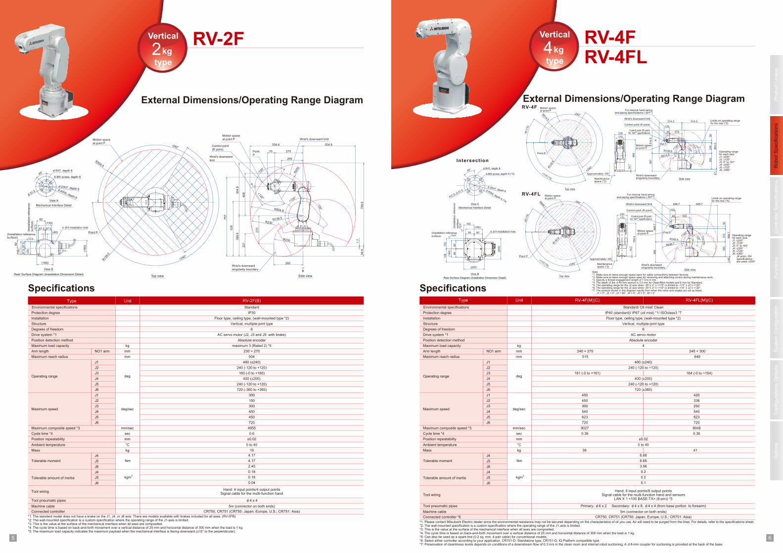
Type Unit RV-2F(B)
230 + 270mmArm length
504mmMaximum reach radius
J1 480 (±240)
J2 240 (-120 to +120)
J4 400 (±200)
J5 240 (-120 to +120)
J6 720 (-360 to +360)
J1 300
J2 150
J6 720
Maximum composite speed *3 mm/sec 4955
Mass kg 19
Environmental specifications Standard
Protection degree IP30
Installation Floor type, ceiling type, (wall-mounted type *2)
Tool wiringHand: 4 input points/4 output points
Signal cable for the multi-function hand
Maximum load capacity kg maximum 3 (Rated 2) *5
J3 160 (-0 to +160)deg
deg/sec
External Dimensions/Operating Range Diagram
RV-2F
NO1 arm
J4
J5
J6
J4
J5
J6
Nm
kgm2
Tolerable moment
Tolerable amount of inertia
4.17
4.17
2.45
0.18
0.18
0.04
RV-4FRV-4FL
External Dimensions/Operating Range Diagram
Specifications
Structure
J3
J4
J5
Cycle time *4
Maximum speed
Position repeatability
Ambient temperature
Machine cable
Connected controller *6
sec
Operating range
mm
°C
300
540
623
0.36
CR750, CR751 (CR750: Japan, Europe, U.S.; CR751: Asia)
Vertical, multiple-joint type
Degrees of freedom 6
Drive system *1 AC servo motor
Position detection method Absolute encoder
±0.02
0 to 40
Tool pneumatic pipes Primary: φ6 x 2 Secondary: φ4 x 8, φ4 x 4 (from base portion to forearm)
5m (connector on both ends)
240 + 270mmArm length
515mmMaximum reach radius
J1 480 (±240)
J2 240 (-120 to +120)
J4 400 (±200)
J5 240 (-120 to +120)
J6
J1 450
J2 450
J6 720
Maximum composite speed *3 mm/sec 9027
Mass kg 39
Environmental specifications Standard/ Oil mist/ Clean
Protection degree IP40 (standard)/ IP67 (oil mist) *1/ ISOclass3 *7
Installation Floor type, ceiling type, (wall-mounted type *2)
Tool wiringHand: 8 input points/8 output points
Signal cable for the multi-function hand and sensorsLAN X 1 <100 BASE-TX> (8-pin)) *5
Maximum load capacity kg 4
J3 161 (-0 to +161)deg
deg/sec
NO1 arm
J4
J5
J6
J4
J5
J6
Nm
kgm2
Tolerable moment
Tolerable amount of inertia
6.66
6.66
3.96
0.2
0.2
0.1
245 + 300
649
250
540
623
0.36
420
336
720
9048
41
*1: The standard model does not have a brake on the J1, J4, or J6 axis. There are models available with brakes included for all axes. (RV-2FB)*2: The wall-mounted specification is a custom specification where the operating range of the J1-axis is limited.*3: This is the value at the surface of the mechanical interface when all axes are composited. *4: The cycle time is based on back-and-forth movement over a vertical distance of 25 mm and horizontal distance of 300 mm when the load is 1 kg.*5: The maximum load capacity indicates the maximum payload when the mechanical interface is facing downward (±10° to the perpendicular).
*1: Please contact Mitsubishi Electric dealer since the environmental resistance may not be secured depending on the characteristics of oil you use. Air will need to be purged from the lines. For details, refer to the specifications sheet. *2: The wall-mounted specification is a custom specification where the operating range of the J1-axis is limited.*3: This is the value at the surface of the mechanical interface when all axes are composited. *4: The cycle time is based on back-and-forth movement over a vertical distance of 25 mm and horizontal distance of 300 mm when the load is 1 kg. *5: Can also be used as a spare line (0.2 sq. mm, 4-pair cable) for conventional models.*6: Select either controller according to your application. CR751-D: Standalone type, CR751-Q: iQ Platform compatible type.*7: Preservation of cleanliness levels depends on conditions of a downstream flow of 0.3 m/s in the clean room and internal robot suctioning. A φ8-mm coupler for suctioning is provided at the back of the base.
Vertical
type
4kg
Vertical
type
2kg
Type Unit RV-4F(M)(C) RV-4FL(M)(C)
Motion space
at point P Wrist's downward limit
Control point
(R point)
Wrist's downward
limit
R13
9.5
+240°
-240°
Top view
R504.6
Point P
Motion space
at point P
280
+120°
38
9.6
-120°
1.7
79
9.6
94
.6
Wrist's downward
singularity boundary
Side view
504.6
-120°
70
504.6
50
4.6
R504.6
R139.5
+120°
Point
P
270
22
1
52
8
75
7
27
0
R230
R230
R250
209
40
8
45°
4-M5 screw, depth 8
φ5H7, depth 8
φ31.5
φ40h8, depth 6
φ20H7, depth 6
View A
Mechanical Interface Detail
(In
sta
llatio
n r
efe
ren
ce
su
rfa
ce
)
4-φ9 installation hole
Rear Surface Diagram (Installation Dimension Detail)
View B
(160)
(16
0)
82
(Installation referencesurface)
82
(135)
67.5 67.5
(40)
Rz
25
Rz 25
67.5
67.5
(135
)
(120
)
A
B
RV-4F
RV-4FL
Intersection
Top view
Motion spaceat point P
Point P
Motion spaceat point P
Wrist's downward limit
Wrist's downwardsingularity boundary
Side view
164 (-0 to +164)
720 (±360)
230
170
690
Approximately 100
Maintenancespace (*2)
Maintenancespace (*2)
Approximately 100
14.7
Motion spaceat point P
Point P
Top view
Motion spaceat point P
Wrist's downward limit
For internal hand wiringand piping specifications (-SH**)
Control point (R point)
Control point (R point)
For internal hand wiringand piping specifications (-SH**)
Control point (R point)for -SH** specifications
Control point (R point)for -SH** specifications
Wrist's downwardsingularity boundary Side view
R136.8
R514.5
397
514.5
47
864.5
514.5 Limits on operating rangefor the rear (*5)
Limits on operating rangefor the rear (*6)
514.5
+240°
-240°
85
125
R13
5.8
R514.5
350
275
235
50
Note*1. Make sure to leave enough space open for cable connections between devices. *2. Make sure to leave enough space open for removing and attaching covers during maintenance work. *3. Specify a thread engagement length of 7.5 to 8 mm. *4. The depth of the φ40-mm section is 3.5 mm for Clean/Mist models and 6 mm for Standard. *5. The operating range for the J2 axis when -35°≤ J1 ≤ +115° is limited to -113° ≤ J2 ≤ +120°. *6. The operating range for the J2 axis when -35°≤ J1 ≤ +110° is limited to -114° ≤ J2 ≤ +120°. *7. The posture shown in the diagram results from when the robot axis angles are set as listed. J1 = 0°, J2 = 0°, J3 = 90°, J4 = 0°, J5 = 0°, J6 = 0°
Operating rangefor each axis:J1: ±240°J2: ±120°J3: 0° to 164°J4: ±200°J5: ±120°J6: ±360° J6 when -SH specifications are used: ±200°
Operating rangefor each axis:J1: ±240°J2: ±120°J3: 0° to 161°J4: ±200°J5: ±120°J6: ±360°
+115°(*5)
-35°(
*5)
-113° (*5
)
-120°
+120°Point P
Point P
R140.4
R648.7
490
648.7
648.7 648.7
140
998.7
85
125
310
350
50
335
+240°
-240°
R14
0.4
R648.7
-114°(*6
)
+110°(*6)
-35°(
*6)
-120°
+120°
230
170
764.9
14.7
A
Rz25
φ40h8, depth 6 (*4)
P.C.D
.φ31.5
φ20H7, depth 6
45° φ5H7, depth 8
4-M5 screw, depth 8 (*3)
(200)1
02
80 80
102
(160)
(160)
(200)
80
80
128
Rz25
View A
Mechanical Interface Detail
View B
Rear Surface Diagram (Installation Dimension Detail)
(Installation reference
surface)
(Insta
llation
refe
rence
surf
ace)
4-φ9 installation hole
-113° (N
ote
1)
1 27 8
Pro
duct
Lin
eup
Robot
Specific
ations
Fu
nctio
ns
Options
Syste
m C
on
fig
ura
tio
nC
onfigura
tions O
ptio
ns
Co
ntr
olle
r S
pecific
ations
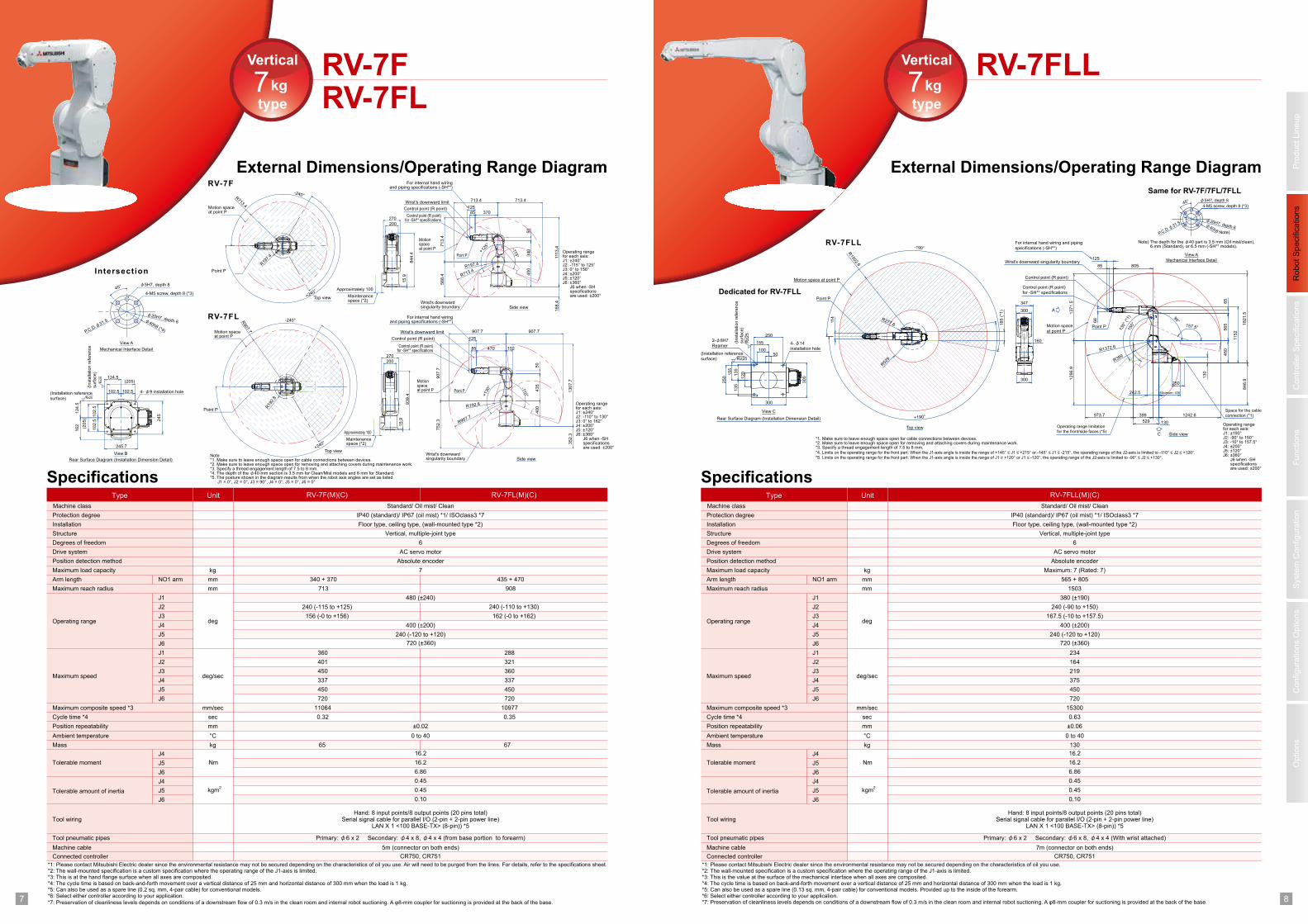
RV-7FRV-7FL
Vertical
type
7kg
External Dimensions/Operating Range Diagram
Specifications
Structure
J3
J4
J5
Cycle time *4
Maximum speed
Position repeatability
Ambient temperature
Machine cable
Connected controller
sec
Operating range
mm
°C
450
337
450
0.32
CR750, CR751
Vertical, multiple-joint type
Degrees of freedom 6
Drive system AC servo motor
Position detection method Absolute encoder
±0.02
0 to 40
Tool pneumatic pipes Primary: φ6 x 2 Secondary: φ4 x 8, φ4 x 4 (from base portion to forearm)
5m (connector on both ends)
Type Unit RV-7F(M)(C)
340 + 370mmArm length
713mmMaximum reach radius
J1 480 (±240)
J2 240 (-115 to +125)
J4 400 (±200)
J5 240 (-120 to +120)
J6
J1 360
J2 401
J6 720
Maximum composite speed *3 mm/sec 11064
Mass kg 65
Machine class Standard/ Oil mist/ Clean
Protection degree IP40 (standard)/ IP67 (oil mist) *1/ ISOclass3 *7
Installation Floor type, ceiling type, (wall-mounted type *2)
Tool wiringHand: 8 input points/8 output points (20 pins total)
Serial signal cable for parallel I/O (2-pin + 2-pin power line)LAN X 1 <100 BASE-TX> (8-pin)) *5
Maximum load capacity kg 7
J3 156 (-0 to +156)deg
deg/sec
NO1 arm
J4
J5
J6
J4
J5
J6
Tolerable moment
Tolerable amount of inertia
16.2
16.2
6.86
0.45
0.45
0.10
RV-7FL(M)(C)
435 + 470
908
360
337
450
0.35
288
321
720
10977
67
*1: Please contact Mitsubishi Electric dealer since the environmental resistance may not be secured depending on the characteristics of oil you use. Air will need to be purged from the lines. For details, refer to the specifications sheet.*2: The wall-mounted specification is a custom specification where the operating range of the J1-axis is limited.*3: This is at the hand flange surface when all axes are composited.*4: The cycle time is based on back-and-forth movement over a vertical distance of 25 mm and horizontal distance of 300 mm when the load is 1 kg.*5: Can also be used as a spare line (0.2 sq. mm, 4-pair cable) for conventional models.*6: Select either controller according to your application.
*7: Preservation of cleanliness levels depends on conditions of a downstream flow of 0.3 m/s in the clean room and internal robot suctioning. A φ8-mm coupler for suctioning is provided at the back of the base.
Nm
kgm2
Intersection
RV-7F
RV-7FL
Side view
Side view
Top view
Top view
240 (-110 to +130)
162 (-0 to +162)
720 (±360)
Rz2
5
Rz25
102.5
102.5
(205)
124.5
124.5
102.5 102.5
(205)
245
162
245.7
P.C.D
.φ31.5
45°
View A
Mechanical Interface Detail
View B
Rear Surface Diagram (Installation Dimension Detail)
(Installation reference
surface)
(Insta
llation r
efe
rence
surf
ace)
4-M5 screw, depth 8 (*3)
φ5H7, depth 8
φ40h8 (*4)
φ20H7, depth 6
4- φ9 installation hole
200
270
844.4
15.9
713.4 713.4
1113.4
713.4
568.4
R197.4
R713.4
168.4
+240°
-240°R713.4
400
340
50
37085
125
R19
7.4
+125
°
-115°
752.3
352.3
R192.8
R907.7
1307.7
+240°
-240°
400
435
50
47085
125
R907.7
907.7
907.7 907.7
R19
2.8
-110°+
130°
102
270
200
939.4
15.9
Operating rangefor each axis:J1: ±240°J2: -115° to 125°J3: 0° to 156°J4: ±200°J5: ±120°J6: ±360° J6 when -SH specifications are used: ±200°
Operating rangefor each axis:J1: ±240°J2: -110° to 130°J3: 0° to 162°J4: ±200°J5: ±120°J6: ±360° J6 when -SH specifications are used: ±200°
Maintenancespace (*2)
Maintenancespace (*2)
Approximately 100
Approximately 100
For internal hand wiringand piping specifications (-SH**)
For internal hand wiringand piping specifications (-SH**)
Wrist's downward limit
Wrist's downward limit
Point P
Point P
Control point (R point)
Control point (R point)
Wrist's downwardsingularity boundary
Wrist's downwardsingularity boundary
Motionspaceat point P
Motionspaceat point P
Control point (R point)for -SH** specifications
Control point (R point)for -SH** specifications
Motion spaceat point P
Motion spaceat point P
Note*1. Make sure to leave enough space open for cable connections between devices. *2. Make sure to leave enough space open for removing and attaching covers during maintenance work. *3. Specify a thread engagement length of 7.5 to 8 mm. *4. The depth of the φ40-mm section is 3.5 mm for Clean/Mist models and 6 mm for Standard. *5. The posture shown in the diagram results from when the robot axis angles are set as listed. J1 = 0°, J2 = 0°, J3 = 90°, J4 = 0°, J5 = 0°, J6 = 0°
Point P
Point P
RV-7FLLVertical
type
7kg
External Dimensions/Operating Range Diagram
Specifications
Structure
J3
J4
J5
Cycle time *4
Maximum speed
Position repeatability
Ambient temperature
Machine cable
Connected controller
sec
Operating range
mm
°C
219
375
450
0.63
CR750, CR751
Vertical, multiple-joint type
Degrees of freedom 6
Drive system AC servo motor
Position detection method Absolute encoder
±0.06
0 to 40
Tool pneumatic pipes Primary: φ6 x 2 Secondary: φ6 x 8, φ4 x 4 (With wrist attached)
7m (connector on both ends)
Type Unit RV-7FLL(M)(C)
565 + 805mmArm length
1503mmMaximum reach radius
J1 380 (±190)
J2 240 (-90 to +150)
J4 400 (±200)
J5 240 (-120 to +120)
J6
J1 234
J2 164
J6 720
Maximum composite speed *3 mm/sec 15300
Mass kg 130
Machine class Standard/ Oil mist/ Clean
Protection degree IP40 (standard)/ IP67 (oil mist) *1/ ISOclass3 *7
Installation Floor type, ceiling type, (wall-mounted type *2)
Tool wiringHand: 8 input points/8 output points (20 pins total)
Serial signal cable for parallel I/O (2-pin + 2-pin power line)LAN X 1 <100 BASE-TX> (8-pin)) *5
Maximum load capacity kg Maximum: 7 (Rated: 7)
J3 167.5 (-10 to +157.5)deg
deg/sec
NO1 arm
J4
J5
J6
J4
J5
J6
Tolerable moment
Tolerable amount of inertia
16.2
16.2
6.86
0.45
0.45
0.10
*1: Please contact Mitsubishi Electric dealer since the environmental resistance may not be secured depending on the characteristics of oil you use.*2: The wall-mounted specification is a custom specification where the operating range of the J1-axis is limited.*3: This is the value at the surface of the mechanical interface when all axes are composited. *4: The cycle time is based on back-and-forth movement over a vertical distance of 25 mm and horizontal distance of 300 mm when the load is 1 kg.*5: Can also be used as a spare line (0.13 sq. mm, 4-pair cable) for conventional models. Provided up to the inside of the forearm. *6: Select either controller according to your application.*7: Preservation of cleanliness levels depends on conditions of a downstream flow of 0.3 m/s in the clean room and internal robot suctioning. A φ8-mm coupler for suctioning is provided at the back of the base.
Nm
kgm2
720 (±360)
Same for RV-7F/7FL/7FLL
View A
Mechanical Interface Detail
φ40h8
P.C.D
.φ31.5
φ20H7, depth 6
45° φ5H7, depth 8
4-M5 screw, depth 8 (*3)
Note)
Note) The depth for the φ40 part is 3.5 mm (Oil mist/clean), 6 mm (Standard), or 6.5 mm (-SH** models).
(*1)
Control point (R point)
Wrist's downward singularity boundary
RV-7FLL
Side view
Control point (R point)
for -SH** specifications
A
View C
Rear Surface Diagram (Installation Dimension Detail)
Motion space at point P
Point P
Top view
For internal hand wiring and piping
specifications (-SH**)
1296.9
1371.5
Motion space
at point P
Space for the cable
connection (*1)
185
114 R277.6
-190°
+190° 399
150° 1
821.5
973.7
90°
R399
846.9
157.5°
1242.6
R1372.6
130
130°
(*1
)
Operating range limitation
for the front/side faces (*5)
R1502.6
Point P
R52
9
529
85 805
1152
65
565
450
242.5
160
300
347
300
Minimum: 430
125
66
130
250
4- φ14
installation hole
2-φ8H7
Reamer
(Installation reference
surface)
(Insta
llation r
efe
rence
surf
ace)
Rz25
Rz25
300
50
155
250
100
135
135
250
155
120
300
C
Dedicated for RV-7FLL
Operating rangefor each axis:J1: ±190°J2: -90° to 150°J3: -10° to 157.5°J4: ±200°J5: ±120°J6: ±360° J6 when -SH specifications are used: ±200°
*1. Make sure to leave enough space open for cable connections between devices. *2. Make sure to leave enough space open for removing and attaching covers during maintenance work. *3. Specify a thread engagement length of 7.5 to 8 mm. *4. Limits on the operating range for the front part: When the J1-axis angle is inside the range of +145° ≤ J1 ≤ +215° or -145° ≤ J1 ≤ -215°, the operating range of the J2-axis is limited to -110° ≤ J2 ≤ +120°. *5. Limits on the operating range for the front part: When the J1-axis angle is inside the range of J1 ≥ +120° or J1 ≤ -120°, the operating range of the J2-axis is limited to -90° ≤ J2 ≤ +130°.
1 29 10
Pro
duct
Lin
eup
Robot
Specific
ations
Fu
nctio
ns
Options
Syste
m C
on
fig
ura
tio
nC
onfigura
tions O
ptio
ns
Co
ntr
olle
r S
pecific
ations
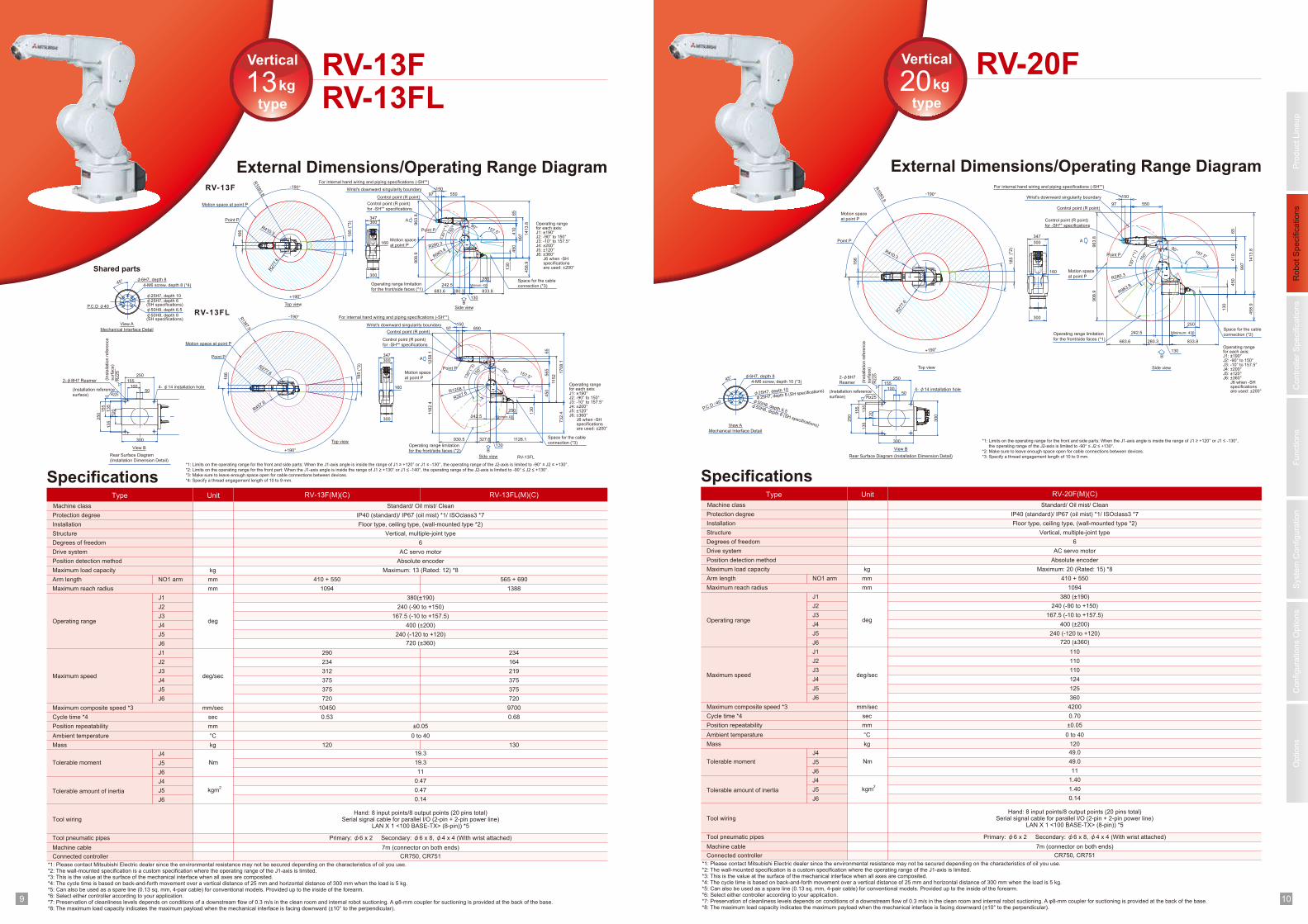
RV-13FRV-13FL
Vertical
type
13kg
External Dimensions/Operating Range Diagram
Specifications
Structure
J3
J4
J5
Cycle time *4
Maximum speed
Position repeatability
Ambient temperature
Machine cable
Connected controller
sec
Operating range
mm
°C
312
375
375
0.53
CR750, CR751
Vertical, multiple-joint type
Degrees of freedom 6
Drive system AC servo motor
Position detection method Absolute encoder
±0.05
0 to 40
Tool pneumatic pipes Primary: φ6 x 2 Secondary: φ6 x 8, φ4 x 4 (With wrist attached)
7m (connector on both ends)
Type Unit RV-13F(M)(C)
410 + 550mmArm length
1094mmMaximum reach radius
J1 380(±190)
J2 240 (-90 to +150)
J4 400 (±200)
J5 240 (-120 to +120)
J6
J1 290
J2 234
J6 720
Maximum composite speed *3 mm/sec 10450
Mass kg 120
Machine class Standard/ Oil mist/ Clean
Protection degree IP40 (standard)/ IP67 (oil mist) *1/ ISOclass3 *7
Installation Floor type, ceiling type, (wall-mounted type *2)
Tool wiringHand: 8 input points/8 output points (20 pins total)
Serial signal cable for parallel I/O (2-pin + 2-pin power line)LAN X 1 <100 BASE-TX> (8-pin)) *5
Maximum load capacity kg Maximum: 13 (Rated: 12) *8
J3 167.5 (-10 to +157.5)deg
deg/sec
NO1 arm
J4
J5
J6
J4
J5
J6
Tolerable moment
Tolerable amount of inertia
19.3
19.3
11
0.47
0.47
0.14
RV-13FL(M)(C)
565 + 690
1388
219
375
375
0.68
234
164
720
9700
130
*1: Please contact Mitsubishi Electric dealer since the environmental resistance may not be secured depending on the characteristics of oil you use. *2: The wall-mounted specification is a custom specification where the operating range of the J1-axis is limited.*3: This is the value at the surface of the mechanical interface when all axes are composited. *4: The cycle time is based on back-and-forth movement over a vertical distance of 25 mm and horizontal distance of 300 mm when the load is 5 kg.*5: Can also be used as a spare line (0.13 sq. mm, 4-pair cable) for conventional models. Provided up to the inside of the forearm. *6: Select either controller according to your application.*7: Preservation of cleanliness levels depends on conditions of a downstream flow of 0.3 m/s in the clean room and internal robot suctioning. A φ8-mm coupler for suctioning is provided at the back of the base.*8: The maximum load capacity indicates the maximum payload when the mechanical interface is facing downward (±10° to the perpendicular).
Nm
kgm2
720 (±360)
RV-20FVertical
type
20kg
External Dimensions/Operating Range Diagram
Specifications
Structure
J3
J4
J5
Cycle time *4
Maximum speed
Position repeatability
Ambient temperature
Machine cable
Connected controller
sec
Operating range
mm
°C
CR750, CR751
Vertical, multiple-joint type
Degrees of freedom 6
Drive system AC servo motor
Position detection method Absolute encoder
±0.05
0 to 40
Tool pneumatic pipes Primary: φ6 x 2 Secondary: φ6 x 8, φ4 x 4 (With wrist attached)
7m (connector on both ends)
Type Unit RV-20F(M)(C)
mmArm length
mmMaximum reach radius
J1 380 (±190)
J2
J4 400 (±200)
J5 240 (-120 to +120)
J6
J1
J2
J6
Maximum composite speed *3 mm/sec
Mass kg
Machine class Standard/ Oil mist/ Clean
Protection degree IP40 (standard)/ IP67 (oil mist) *1/ ISOclass3 *7
Installation Floor type, ceiling type, (wall-mounted type *2)
Tool wiringHand: 8 input points/8 output points (20 pins total)
Serial signal cable for parallel I/O (2-pin + 2-pin power line)LAN X 1 <100 BASE-TX> (8-pin)) *5
Maximum load capacity kg Maximum: 20 (Rated: 15) *8
J3deg
deg/sec
NO1 arm
J4
J5
J6
J4
J5
J6
Tolerable moment
Tolerable amount of inertia
49.0
49.0
11
1.40
1.40
0.14
410 + 550
1094
110
124
125
0.70
110
110
360
4200
120
*1: Please contact Mitsubishi Electric dealer since the environmental resistance may not be secured depending on the characteristics of oil you use.*2: The wall-mounted specification is a custom specification where the operating range of the J1-axis is limited.*3: This is the value at the surface of the mechanical interface when all axes are composited. *4: The cycle time is based on back-and-forth movement over a vertical distance of 25 mm and horizontal distance of 300 mm when the load is 5 kg.*5: Can also be used as a spare line (0.13 sq. mm, 4-pair cable) for conventional models. Provided up to the inside of the forearm. *6: Select either controller according to your application.*7: Preservation of cleanliness levels depends on conditions of a downstream flow of 0.3 m/s in the clean room and internal robot suctioning. A φ8-mm coupler for suctioning is provided at the back of the base.*8: The maximum load capacity indicates the maximum payload when the mechanical interface is facing downward (±10° to the perpendicular).
Nm
kgm2
240 (-90 to +150)
167.5 (-10 to +157.5)
720 (±360)
450
410
65
242.5
997
250
130
Minimum: 430
300
250
135
155
155
135
120
250
10050
300347
166
160
300
P.C.D φ40
2-φ8H7 Reamer
4- φ14 installation hole
45°
185
(*3)
683.6
150°
280.3
1413.8
458.9
157.5°
550
Point P
97
130
833.8
R1093.8
-190°
+190°
R410.3
R280.3
Control point (R point)
Wrist's downward singularity boundary
R963.8
90°
130°(
*1)
Operating range limitation
for the front/side faces (*1)
Side view
150
Control point (R point)
for -SH** specifications
A
View A
Mechanical Interface Detail
View B
Rear Surface Diagram
(Installation Dimension Detail)
R27
7.6
Motion space at point P
Point P
Top view
For internal hand wiring and piping specifications (-SH**)
908.9
963.8
Motion space
at point P
Space for the cable
connection (*3)
Rz25
Rz25
*1: Limits on the operating range for the front and side parts: When the J1-axis angle is inside the range of J1 ≥ +120° or J1 ≤ -130°, the operating range of the J2-axis is limited to -90° ≤ J2 ≤ +130°. *2: Limits on the operating range for the front part: When the J1-axis angle is inside the range of J1 ≥ +130° or J1 ≤ -140°, the operating range of the J2-axis is limited to -90° ≤ J2 ≤ +130°. *3: Make sure to leave enough space open for cable connections between devices.
*4: Specify a thread engagement length of 10 to 9 mm.
Shared parts
RV-13F
RV-13FLφ50H8, depth 8(SH specifications)
φ25H7, depth 6(SH specifications)
Point P
Control point (R point)
Wrist's downward singularity boundary
Operating range limitation
for the front/side faces (*2)
RV-13FLSide view
Control point (R point)
for -SH** specifications
A
Motion space at point P
Point P
Top view
For internal hand wiring and piping specifications (-SH**)
1182.4
12
58.1
Motion space
at point P
Space for the cable
connection (*3)
90° 157.5°
732.4
1708.1
930.5
150°
R1258.1
R327.6
R457.6
130
327.6 1128.1
130°(
*3)
R1387.9
-190°
+190°
1152
65
565
450
347
160
300
242.5
69097
166
R277.6
Minimum: 430
150
300
130
12°
185
250
B
B
(Installation reference
surface)
(Insta
llation r
efe
rence
surf
ace)
4-M6 screw, depth 8 (*4)
φ6H7, depth 8
φ25H7, depth 10
φ50H8, depth 6.5
(*3)
Operating rangefor each axis:J1: ±190°J2: -90° to 150°J3: -10° to 157.5°J4: ±200°J5: ±120°J6: ±360° J6 when -SH specifications are used: ±200°
Operating rangefor each axis:J1: ±190°J2: -90° to 150°J3: -10° to 157.5°J4: ±200°J5: ±120°J6: ±360° J6 when -SH specifications are used: ±200°
450
410
65
242.5
997
250
130
Minimum: 430
300
250
135
155
155
135
120
300
250
10050
300
347
166
160
300
P.C.D ∅40 φ50H8, depth 6.5
φ25H7, depth 10
2-φ8H7
Reamer
4- φ14 installation hole
φ6H7, depth 845°
4-M6 screw, depth 10 (*3)
185
φ25H7, depth 6 (SH specifications)
φ50H8, depth 8 (SH specifications)
(*2)
683.6
150°
280.3
1413.8
458.9
157.5°
550
Point P
97
130
833.8
R1093.8
-190°
+190°
R410.3
R280.3
Control point (R point)
Wrist's downward singularity boundary
R963.8
90°
130°
(*1)
Operating range limitation
for the front/side faces (*1)
Side view
150
Control point (R point)
for -SH** specifications
A
View A
Mechanical Interface Detail
View B
Rear Surface Diagram (Installation Dimension Detail)
R27
7.6
Motion space
at point P
Point P
Top view
For internal hand wiring and piping specifications (-SH**)
908.9
963.8
Motion space
at point P
B
Space for the cable
connection (*2)
Rz25
Rz25
*1: Limits on the operating range for the front and side parts: When the J1-axis angle is inside the range of J1 ≥ +120° or J1 ≤ -130°, the operating range of the J2-axis is limited to -90° ≤ J2 ≤ +130°.
*2: Make sure to leave enough space open for cable connections between devices.
*3: Specify a thread engagement length of 10 to 9 mm.
(Installation reference
surface)
(Insta
llation
refe
rence
surf
ace)
Operating rangefor each axis:J1: ±190°J2: -90° to 150°J3: -10° to 157.5°J4: ±200°J5: ±120°J6: ±360° J6 when -SH specifications are used: ±200°
212111
Pro
duct
Lin
eup
Robot
Specific
ations
Fu
nctio
ns
Options
Syste
m C
on
fig
ura
tio
nC
onfigura
tions O
ptio
ns
Co
ntr
olle
r S
pecific
ations
Horizontal
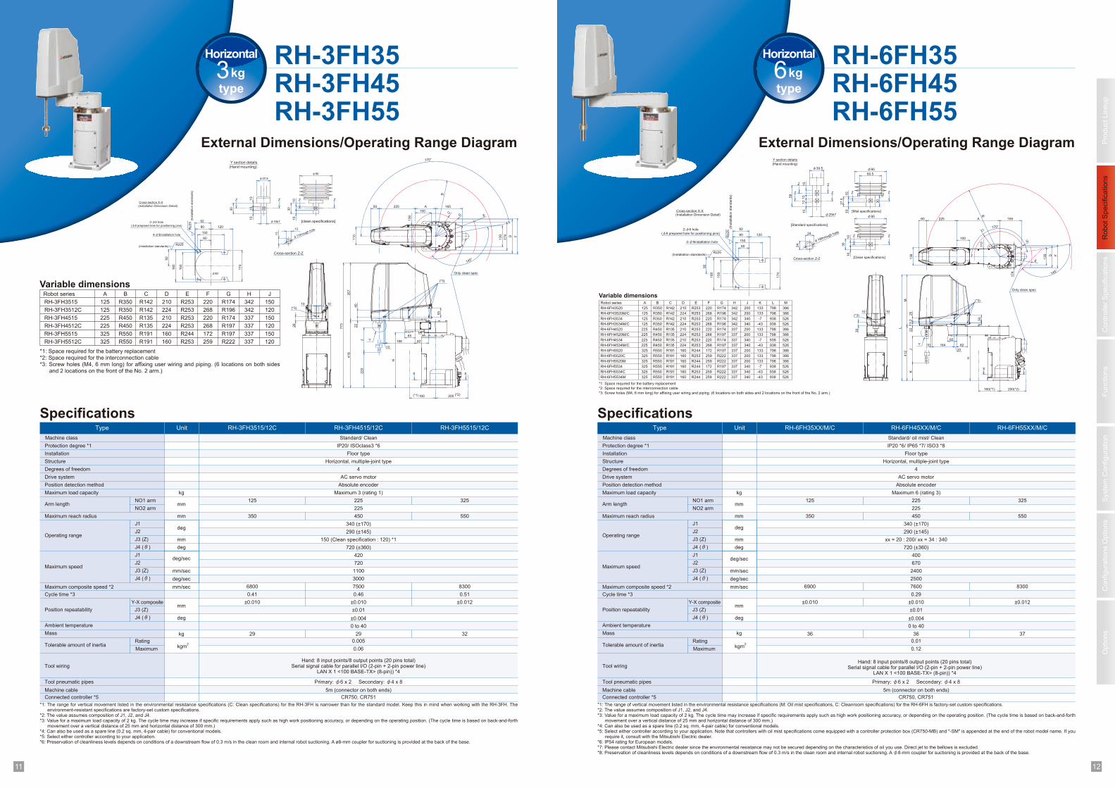
type6kg
External Dimensions/Operating Range Diagram
RH-6FH35RH-6FH45RH-6FH55
Specifications
Structure
J3 (Z)
J4 (θ)
Cycle time *3
Maximum speed
Position repeatability
Ambient temperature
Machine cable
Connected controller *5
Operating range
6900
CR750, CR751
Degrees of freedom 4
Drive system AC servo motor
Position detection method Absolute encoder
±0.010
0 to 40
Tool pneumatic pipes Primary: φ6 x 2 Secondary: φ4 x 8
5m (connector on both ends)
Type Unit RH-6FH35XX/M/C
Arm length
350mmMaximum reach radius
J1 340 (±170)
J2 290 (±145)
720 (±360)
400
670
J1
2400
J2
2500
Maximum composite speed *2 mm/sec
Mass kg 36
Machine class Standard/ oil mist/ Clean
Protection degree *1 IP20 *6/ IP65 *7/ ISO3 *8
Installation Floor type
Tool wiringHand: 8 input points/8 output points (20 pins total)
Serial signal cable for parallel I/O (2-pin + 2-pin power line)LAN X 1 <100 BASE-TX> (8-pin)) *4
Maximum load capacity kg Maximum 6 (rating 3)
xx = 20 : 200/ xx = 34 : 340
NO1 arm
Rating
MaximumTolerable amount of inertia
0.01
0.12
RH-6FH55XX/M/C
325
550
8300
37
*1: The range of vertical movement listed in the environmental resistance specifications (M: Oil mist specifications, C: Cleanroom specifications) for the RH-6FH is factory-set custom specifications.*2: The value assumes composition of J1, J2, and J4.*3: Value for a maximum load capacity of 2 kg. The cycle time may increase if specific requirements apply such as high work positioning accuracy, or depending on the operating position. (The cycle time is based on back-and-forth
movement over a vertical distance of 25 mm and horizontal distance of 300 mm.)*4: Can also be used as a spare line (0.2 sq. mm, 4-pair cable) for conventional models.*5: Select either controller according to your application. Note that controllers with oil mist specifications come equipped with a controller protection box (CR750-MB) and "-SM" is appended at the end of the robot model name. If you
require it, consult with the Mitsubishi Electric dealer.*6: IP54 rating for European models.*7: Please contact Mitsubishi Electric dealer since the environmental resistance may not be secured depending on the characteristics of oil you use. Direct jet to the bellows is excluded. *8: Preservation of cleanliness levels depends on conditions of a downstream flow of 0.3 m/s in the clean room and internal robot suctioning. A φ8-mm coupler for suctioning is provided at the back of the base.
deg
deg/sec
kgm2
RH-6FH45XX/M/C
Horizontal, multiple-joint type
NO2 armmm
mm
deg
deg/sec
mm/sec
J3 (Z)
J4 (θ)
Y-X composite
J3 (Z)
J4 (θ)
deg
mm
125 225
225
450
7600
0.29
±0.012
±0.004
±0.01
Robot series A B C D E F G H J K L M
RH-6FH3520 125 R350 R142 210 R253 220 R174 342 200 133 798 386
RH-6FH3520M/C 125 R350 R142 224 R253 268 R196 342 200 133 798 386
RH-6FH3534 125 R350 R142 210 R253 220 R174 342 340 -7 938 526
RH-6FH3534M/C 125 R350 R142 224 R253 268 R196 342 340 -43 938 526
RH-6FH4520 225 R450 R135 210 R253 220 R174 337 200 133 798 386
RH-6FH4520M/C 225 R450 R135 224 R253 268 R197 337 200 133 798 386
RH-6FH4534 225 R450 R135 210 R253 220 R174 337 340 -7 938 526
RH-6FH4534M/C 225 R450 R135 224 R253 268 R197 337 340 -43 938 526
RH-6FH5520 325 R550 R191 160 R244 172 R197 337 200 133 798 386
RH-6FH5520C 325 R550 R191 160 R253 259 R222 337 200 133 798 386
RH-6FH5520M 325 R550 R191 160 R244 259 R222 337 200 133 798 386
RH-6FH5534 325 R550 R191 160 R244 172 R197 337 340 -7 938 526
RH-6FH5534C 325 R550 R191 160 R253 259 R222 337 340 -43 938 526
RH-6FH5534M 325 R550 R191 160 R244 259 R222 337 340 -43 938 526
Variable dimensions
22
13.2
25
M
J136
L
412
K
1010
30
(*3)
55
4
H
16410
65
20
82
200(*2)160(*1)
X X
(*3)
110
A60
100
225
174
130
165
145°
D F
BC
E
170°
G
58
Z
Z
27.5
60.5
Z15
10
10
10
30
10
24
24Z
10
10
Z Z
Z
30
Z
Y
150
12090
92
180
150
92
60
174
Rz25
Rz25
10
(Installation Dimension Detail)Cross-section X-X
4-φ9installation hole
(Installation standards)
2-φ6 hole
(φ8 prepared hole for positioning pins)
(Insta
llation s
tandard
s)
Y section details
(Hand mounting)
[Mist specifications]
φ90
[Clean specifications]
[Standard specifications]
φ18through hole
Cross-section Z-Z
φ25h7
φ90φ39.5
Only clean spec
±0.010
36
*1: Space required for the battery replacement
*2: Space required for the interconnection cable
*3: Screw holes (M4, 6 mm long) for affixing user wiring and piping. (6 locations on both sides and 2 locations on the front of the No. 2 arm.)
Horizontal
type3kg
External Dimensions/Operating Range Diagram
RH-3FH35RH-3FH45RH-3FH55
Specifications
Structure
J3 (Z)
J4 (θ)
Cycle time *3
Maximum speed
Position repeatability
Ambient temperature
Machine cable
Connected controller *5
Operating range
6800
0.41
CR750, CR751
Degrees of freedom 4
Drive system AC servo motor
Position detection method Absolute encoder
±0.010
0 to 40
Tool pneumatic pipes Primary: φ6 x 2 Secondary: φ4 x 8
5m (connector on both ends)
Type Unit RH-3FH3515/12C
Arm length
350mmMaximum reach radius
J1 340 (±170)
J2 290 (±145)
720 (±360)
420
720
J1
1100
J2
3000
Maximum composite speed *2 mm/sec
Mass kg 29
Machine class Standard/ Clean
Protection degree *1 IP20/ ISOclass3 *6
Installation Floor type
Tool wiringHand: 8 input points/8 output points (20 pins total)
Serial signal cable for parallel I/O (2-pin + 2-pin power line)LAN X 1 <100 BASE-TX> (8-pin)) *4
Maximum load capacity kg Maximum 3 (rating 1)
150 (Clean specification : 120) *1
NO1 arm
Rating
MaximumTolerable amount of inertia
0.005
0.06
RH-3FH5515/12C
325
550
8300
0.51
32
*1: The range for vertical movement listed in the environmental resistance specifications (C: Clean specifications) for the RH-3FH is narrower than for the standard model. Keep this in mind when working with the RH-3FH. The environment-resistant specifications are factory-set custom specifications.
*2: The value assumes composition of J1, J2, and J4.*3: Value for a maximum load capacity of 2 kg. The cycle time may increase if specific requirements apply such as high work positioning accuracy, or depending on the operating position. (The cycle time is based on back-and-forth
movement over a vertical distance of 25 mm and horizontal distance of 300 mm.)*4: Can also be used as a spare line (0.2 sq. mm, 4-pair cable) for conventional models.*5: Select either controller according to your application.*6: Preservation of cleanliness levels depends on conditions of a downstream flow of 0.3 m/s in the clean room and internal robot suctioning. A ø8-mm coupler for suctioning is provided at the back of the base.
deg
deg/sec
kgm2
RH-3FH4515/12C
Horizontal, multiple-joint type
NO2 armmm
mm
deg
deg/sec
mm/sec
J3 (Z)
J4 (θ)
Y-X composite
J3 (Z)
J4 (θ)
deg
mm
125 225
225
450
7500
0.46
±0.012
±0.004
±0.01
*1: Space required for the battery replacement*2: Space required for the interconnection cable*3: Screw holes (M4, 6 mm long) for affixing user wiring and piping. (6 locations on both sides
and 2 locations on the front of the No. 2 arm.)
Variable dimensionsRobot series A B C D E F G H J
RH-3FH3515 125 R350 R142 210 R253 220 R174 342 150
RH-3FH3512C 125 R350 R142 224 R253 268 R196 342 120
RH-3FH4515 225 R450 R135 210 R253 220 R174 337 150
RH-3FH4512C 225 R450 R135 224 R253 268 R197 337 120
RH-3FH5515 325 R550 R191 160 R244 172 R197 337 150
RH-3FH5512C 325 R550 R191 160 R253 259 R222 337 120773
416
10
220
H
10
15
15
160
X
(*1) 200 (*2)
X
174
Z10
30
Z Z
30
10 Z
136
100
50 165
110
22
10
40
357
10
26
10
(*3)
J 82188
65
55
(*3)
130
225 A
145°
EG
170°
FD
B
C
150
12090
92
180
150
92
60174
Y
Rz25
Rz25
Cross-section Z-Z10
φ11through hole
[clean specifications]φ16h7
φ37.5
(Hand mounting)
Y section details
φ90
(Installation Dimension Detail)
Cross-section X-X
4-φ9installation hole
(Installation standards)
2-φ6 hole
(φ8 prepared hole for positioning pins)
(Insta
llation s
tandard
s)
φ90
Only clean spec
±0.010
29
1 213 14
Pro
duct
Lin
eup
Robot
Specific
ations
Fu
nctio
ns
Options
Syste
m C
on
fig
ura
tio
nC
onfigura
tions O
ptio
ns
Co
ntr
olle
r S
pecific
ations
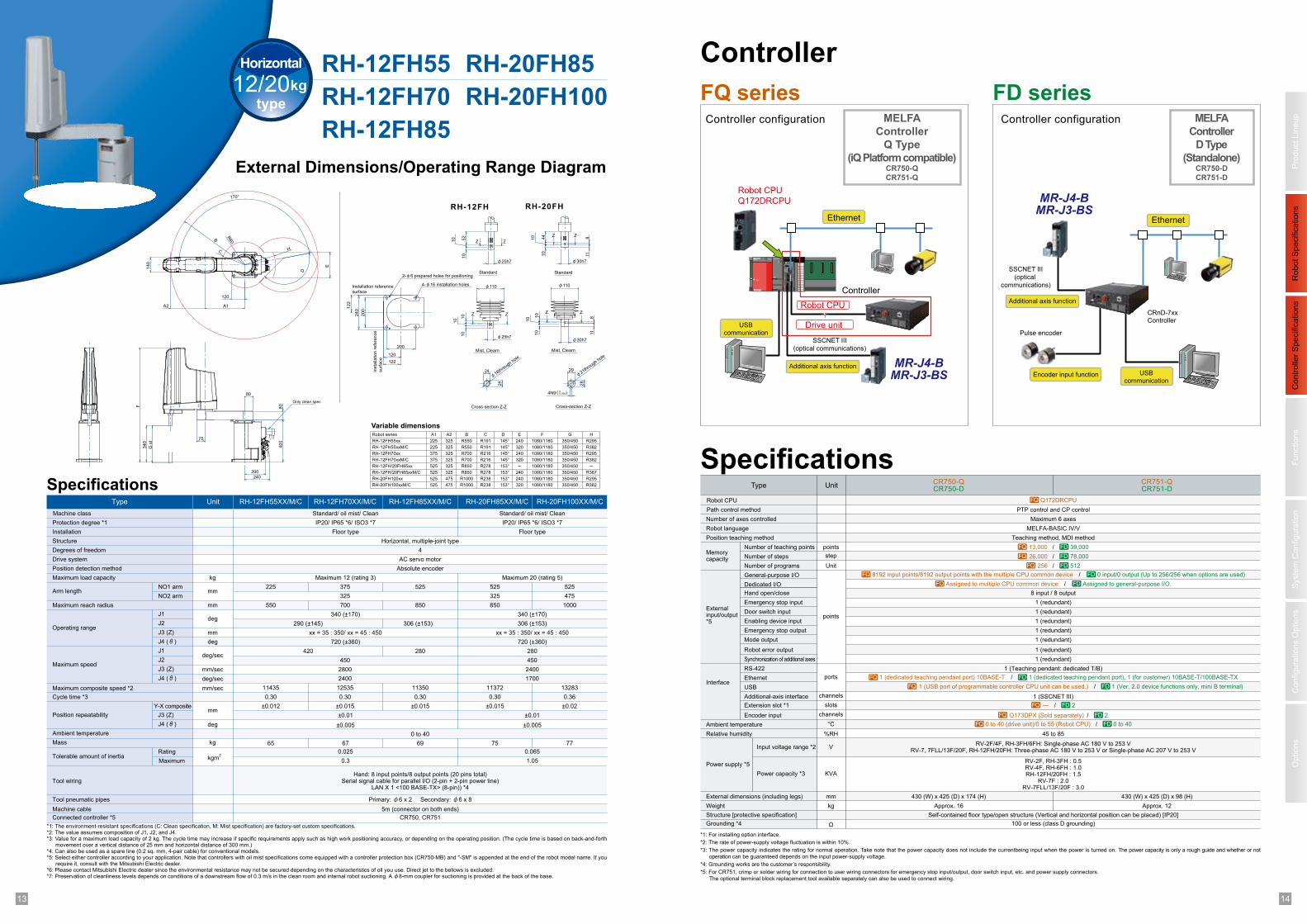
Controller
Specifications
Controller configuration
Type
Path control method
Robot CPU
Number of axes controlled
Robot language
Position teaching method
Memory capacity
Externalinput/output*5
Interface
Number of teaching points
Number of steps
Number of programs
General-purpose I/O
Dedicated I/O
Hand open/close
Emergency stop input
Door switch input
Enabling device input
Grounding *4
Structure [protective specification]
Weight
External dimensions (including legs)
Power supply *5
Relative humidity
Ambient temperature
PTP control and CP control
Maximum 6 axes
MELFA-BASIC IV/V
Teaching method, MDI method
100 or less (class D grounding)
Self-contained floor type/open structure (Vertical and horizontal position can be placed) [IP20]
45 to 85
Unit
points
step
Unit
points
slots
ports
channels
channels
V
°C
%RH
Ω
kg
mm
KVA
Emergency stop output
Mode output
Robot error output
Synchronization of additional axes
RS-422
Ethernet
USB
Input voltage range *2
Power capacity *3
Additional-axis interface
FQ series FD seriesController configuration
CR750-QCR750-D
CR751-QCR751-D
Encoder input
8 input / 8 output
1 (redundant)
1 (redundant)
1 (redundant)
1 (redundant)
1 (redundant)
1 (redundant)
1 (redundant)
1 (Teaching pendant: dedicated T/B)
RV-2F/4F, RH-3FH/6FH: Single-phase AC 180 V to 253 VRV-7, 7FLL/13F/20F, RH-12FH/20FH: Three-phase AC 180 V to 253 V or Single-phase AC 207 V to 253 V
RV-2F, RH-3FH : 0.5RV-4F, RH-6FH : 1.0RH-12FH/20FH : 1.5
RV-7F : 2.0RV-7FLL/13F/20F : 3.0
1 (SSCNET III)
*1: For installing option interface.
*2: The rate of power-supply voltage fluctuation is within 10%.
*3: The power capacity indicates the rating for normal operation. Take note that the power capacity does not include the currentbeing input when the power is turned on. The power capacity is only a rough guide and whether or not
operation can be guaranteed depends on the input power-supply voltage.
*4: Grounding works are the customer’s responsibility.
*5: For CR751, crimp or solder wiring for connection to user wiring connectors for emergency stop input/output, door switch input, etc. and power supply connectors.
The optional terminal block replacement tool available separately can also be used to connect wiring.
/ 8192 input points/8192 output points with the multiple CPU common deviceFQ 0 input/0 output (Up to 256/256 when options are used)FD
/ Assigned to multiple CPU common device.FQ Assigned to general-purpose I/O.FD
1 (dedicated teaching pendant port) 10BASE-TFQ 1 (dedicated teaching pendant port), 1 (for customer) 10BASE-T/100BASE-TXFD/
/1 (USB port of programmable controller CPU unit can be used.)FQ 1 (Ver. 2.0 device functions only, mini B terminal)FD
430 (W) x 425 (D) x 174 (H) 430 (W) x 425 (D) x 98 (H)
Approx. 16 Approx. 12
Q172DRCPUFQ
/Q173DPX (Sold separately)FQ 2FD
/―FQ 2FD
/0 to 40 (drive unit)/0 to 55 (Robot CPU)FQ 0 to 40FD
Ethernet
Robot CPU
Q172DRCPU
Controller
Robot CPU
Drive unitUSBcommunication
Additional axis function MR-J4-B
MR-J3-BS
MR-J4-B
MR-J3-BS
SSCNET III
(optical communications)
SSCNET III
(optical
communications)
Ethernet
Pulse encoder
CRnD-7xxController
USBcommunication
Additional axis function
MELFA
Controller
D Type
(Standalone)CR750-D
CR751-D
MELFA
Controller
Q Type
(iQ Platform compatible)CR750-Q
CR751-Q
Encoder input function
Extension slot *1
/13,000FQ 39,000FD
/26,000FQ 78,000FD
/256FQ 512FD
Horizontal
type12/20kg
External Dimensions/Operating Range Diagram
RH-12FH55
RH-12FH70
RH-12FH85
Specifications
Structure
J3 (Z)
J4 (θ)
Cycle time *3
Maximum speed
Position repeatability
Ambient temperature
Machine cable
Connected controller *5
Operating range
11435
Degrees of freedom 4
Drive system AC servo motor
Position detection method Absolute encoder
±0.012
0 to 40
Tool pneumatic pipes Primary: φ6 x 2 Secondary: φ6 x 8
5m (connector on both ends)
Type Unit RH-12FH55XX/M/C
Arm length
550mmMaximum reach radius
J1 340 (±170)
J2 290 (±145)
720 (±360)
420
450
J1
2400
J2
1700
Maximum composite speed *2 mm/sec
Mass kg 65
Machine class Standard/ oil mist/ Clean
Protection degree *1 IP20/ IP65 *6/ ISO3 *7
Installation Floor type
Tool wiringHand: 8 input points/8 output points (20 pins total)
Serial signal cable for parallel I/O (2-pin + 2-pin power line)LAN X 1 <100 BASE-TX> (8-pin)) *4
Maximum load capacity kg Maximum 12 (rating 3)
xx = 35 : 350/ xx = 45 : 450
NO1 arm
Rating
MaximumTolerable amount of inertia
0.025
0.3
RH-20FH100XX/M/C
525
850
13283
77
*1: The environment-resistant specifications (C: Clean specification, M: Mist specification) are factory-set custom specifications. *2: The value assumes composition of J1, J2, and J4.*3: Value for a maximum load capacity of 2 kg. The cycle time may increase if specific requirements apply such as high work positioning accuracy, or depending on the operating position. (The cycle time is based on back-and-forth
movement over a vertical distance of 25 mm and horizontal distance of 300 mm.)*4: Can also be used as a spare line (0.2 sq. mm, 4-pair cable) for conventional models.*5: Select either controller according to your application. Note that controllers with oil mist specifications come equipped with a controller protection box (CR750-MB) and "-SM" is appended at the end of the robot model name. If you
require it, consult with the Mitsubishi Electric dealer.*6: Please contact Mitsubishi Electric dealer since the environmental resistance may not be secured depending on the characteristics of oil you use. Direct jet to the bellows is excluded. *7: Preservation of cleanliness levels depends on conditions of a downstream flow of 0.3 m/s in the clean room and internal robot suctioning. A φ8-mm coupler for suctioning is provided at the back of the base.
deg
deg/sec
kgm2
RH-12FH70XX/M/C
Horizontal, multiple-joint type
NO2 armmm
mm
deg
deg/sec
mm/sec
J3 (Z)
J4 (θ)
Y-X composite
J3 (Z)
J4 (θ)
deg
mm
225 525
325
850
11350
0.30
±0.02
±0.005
±0.01
RH-20FH85
RH-20FH100
RH-12FH85XX/M/C RH-20FH85XX/M/C
700
375 525
1000
475
306 (±153)
280
2800
2400
12535 11372
0.36
±0.015
67 69 75
0.065
1.05
Robot series A1
RH-12FH55xx 225
RH-12FH55xxM/C 225
RH-12FH70xx 375
RH-12FH70xxM/C 375
RH-12FH/20FH85xx 525
RH-12FH/20FH85xxM/C 525
RH-20FH100xx 525
RH-20FH100xxM/C 525
A2
325
325
325
325
325
325
475
475
B
R550
R550
R700
R700
R850
R850
R1000
R1000
C
R191
R191
R216
R216
R278
R278
R238
R238
D
145°
145°
145°
145°
153°
153°
153°
153°
E
240
320
240
320
─240
240
320
F
1080/1180
1080/1180
1080/1180
1080/1180
1080/1180
1080/1180
1080/1180
1080/1180
G
350/450
350/450
350/450
350/450
350/450
350/450
350/450
350/450
H
R295
R382
R295
R382
─R367
R295
R382
Variable dimensions
F
340
400
80
80
200240
75
A1A2
140
120
B
R80
C
170°
D
E
H
G s
t
120
122
240
122
200
200
4-φ16 installation holesInstallation reference
surface
Insta
llation r
efe
rence
surf
ace
28
29
)( -0.030 0
4N9
24
24
10
10
10
Z Z
Standard
RH-12FH
10
811
10 1
0 Z Z
RH-20FH
2-φ6 prepared holes for positioning
10
811
10 44
10
10 52
Z
Z Z
Z
Only clean spec
φ25h7 φ30h7
φ110 φ110
φ30h7φ25h7
φ21th
rough h
ole
Mist, Clearn
Cross-section Z-Z Cross-section Z-Z
Mist, Clearn
φ18th
rough h
ole
Standard
Standard/ oil mist/ Clean
IP20/ IP65 *6/ ISO3 *7
Floor type
Maximum 20 (rating 5)
325
340 (±170)
306 (±153)
xx = 35 : 350/ xx = 45 : 450
720 (±360)
280
450
0.300.30 0.30
±0.015 ±0.015
±0.005
±0.01
CR750, CR751
1 215 16
Pro
duct
Lin
eup
Robot
Specific
ations
Fu
nctio
ns
Options
Syste
m C
on
fig
ura
tio
nC
onfigura
tions O
ptio
ns
Co
ntr
olle
r S
pecific
ations
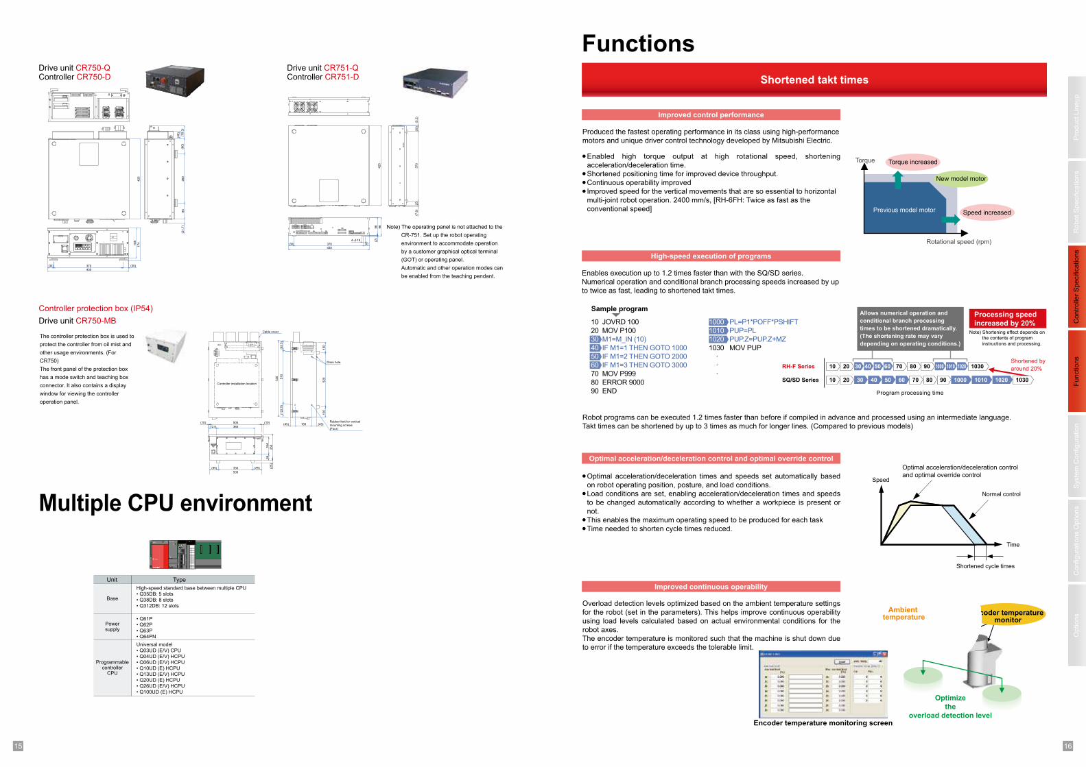
Overload detection levels optimized based on the ambient temperature settings
for the robot (set in the parameters). This helps improve continuous operability
using load levels calculated based on actual environmental conditions for the
robot axes.
The encoder temperature is monitored such that the machine is shut down due
to error if the temperature exceeds the tolerable limit.
●
●
●●
Optimal acceleration/deceleration times and speeds set automatically based
on robot operating position, posture, and load conditions.
Load conditions are set, enabling acceleration/deceleration times and speeds
to be changed automatically according to whether a workpiece is present or
not.
This enables the maximum operating speed to be produced for each task
Time needed to shorten cycle times reduced.
Shortened takt times
Produced the fastest operating performance in its class using high-performance
motors and unique driver control technology developed by Mitsubishi Electric.
Enables execution up to 1.2 times faster than with the SQ/SD series.
Numerical operation and conditional branch processing speeds increased by up
to twice as fast, leading to shortened takt times.
Robot programs can be executed 1.2 times faster than before if compiled in advance and processed using an intermediate language.
Takt times can be shortened by up to 3 times as much for longer lines. (Compared to previous models)
Enabled high torque output at high rotational speed, shortening
acceleration/deceleration time.
Shortened positioning time for improved device throughput.
Continuous operability improved
Improved speed for the vertical movements that are so essential to horizontal
multi-joint robot operation. 2400 mm/s, [RH-6FH: Twice as fast as the
conventional speed]
●
●●●
Improved control performance
High-speed execution of programs
Optimal acceleration/deceleration control and optimal override control
Improved continuous operability
Functions
Rotational speed (rpm)
Torque
Previous model motor
Torque increased
Speed increased
Shortened by
around 20%
Processing speed
increased by 20% 10 JOVRD 100
20 MOV P100
30 M1=M_IN (10)
40 IF M1=1 THEN GOTO 1000
50 IF M1=2 THEN GOTO 2000
60 IF M1=3 THEN GOTO 3000
70 MOV P999
80 ERROR 9000
90 END
1000 PL=P1*POFF*PSHIFT
1010 PUP=PL
1020 PUP.Z=PUP.Z+MZ
1030 MOV PUP
·
·
·RH-F Series
SQ/SD Series
Program processing time
10 20 30 40 50 60 70 80 90 1000 1010 1020 1030
10 20 30 40 50 60 1000 1010 102070 80 90 1030
Allows numerical operation and
conditional branch processing
times to be shortened dramatically.
(The shortening rate may vary
depending on operating conditions.)
Sample program
Note) Shortening effect depends on
the contents of program
instructions and processing.
Shortened cycle times
Optimal acceleration/deceleration control
and optimal override control
Normal control
Time
Speed
New model motor
Encoder temperature monitor
Optimize
the
overload detection levelEncoder temperature monitoring screen
Ambient temperature
Drive unit CR750-Q Drive unit CR751-Q
Drive unit CR750-MB
Controller CR750-D Controller CR751-D
Multiple CPU environment
Unit
Base
Powersupply
Programmablecontroller
CPU
Type
High-speed standard base between multiple CPU
• Q35DB: 5 slots• Q38DB: 8 slots• Q312DB: 12 slots
Universal model
• Q03UD (E/V) CPU• Q04UD (E/V) HCPU• Q06UD (E/V) HCPU• Q10UD (E) HCPU• Q13UD (E/V) HCPU• Q20UD (E) HCPU• Q26UD (E/V) HCPU• Q100UD (E) HCPU
• Q61P• Q62P• Q63P• Q64PN
425
260
85
(80)
(70.3
)
(40)
(21.7
)
158
174
370
430
(30) (30)
Note) The operating panel is not attached to the
CR-751. Set up the robot operating
environment to accommodate operation
by a customer graphical optical terminal
(GOT) or operating panel.
Automatic and other operation modes can
be enabled from the teaching pendant.
425
98
96
(2)
370
25
(30
)(5
.2)
(7.8
)
370
430
4-φ18
(30) 30
Cable cover
Drain hole
Rubber feet for vertical
mounting screws
(Four)
Controller installation location
(92.5
)(1
22.5
)
(45) 160(10)(10) 505
36572.5
330
500
(85) (85) (25)
250
164
55
(45)
510
520
100
100
725
Controller protection box (IP54)
The controller protection box is used to
protect the controller from oil mist and
other usage environments. (For
CR750)
The front panel of the protection box
has a mode switch and teaching box
connector. It also contains a display
window for viewing the controller
operation panel.
1 217 18
Pro
duct
Lin
eup
Robot
Specific
ations
Fu
nctio
ns
Options
Syste
m C
on
fig
ura
tio
nC
onfigura
tions O
ptio
ns
Co
ntr
olle
r S
pecific
ations
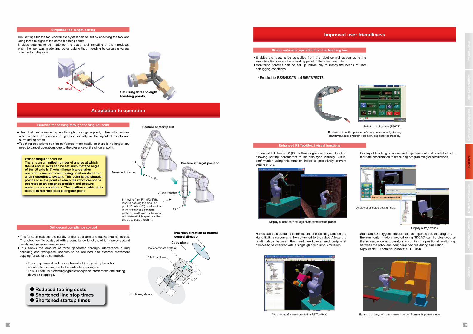
Improved accuracy
Optimal motor control tuning set automatically based on robot operating
position, posture, and load conditions.
Improves tracking accuracy for the target trajectory.
●
●
Monitor the robot posture and load conditionsAutomatic tuning
Load
Target track
With active gain control
Without active gain control
●
●
●
Trajectory priority mode/speed priority operation can be set in programs to
match customer system requirements.
Optimal motor control tuning set automatically based on robot operating
position, posture, and load conditions.
Improves tracking accuracy for the target trajectory.
●●
●
Compensates for deflection in the robot arm occurring due to gravity.
Calculates the amount of compensation needed based on the operating
position, posture, and load conditions of the robot and compensates for any
deflection automatically.
Compensates not only for static deflection due to gravitational pull but also for
dynamic deflection due to the inertial force present during operation.
Active gain control
Deflection compensation function
Operating mode setting function
High speed
Hig
h a
ccu
racy
Standard settings
high-speed positioning
mode
High-accuracy trajectory mode
MvTune 1
MvTune 2
MvTune 3
Deflection
compensation
kθ
· Effective for work transporting workpieces to cassettes with low pitch and palletizing work.
Improved palletization accuracyImproved trajectory accuracy
compensation
Improved trajectory accuracyImproved vibration-damping performance
· Active gain control is a control method that allows the position gain to be changed in real time.
· This is effective for standard operations and tooling work requiring high accuracy.
· This is effective for standard operations and tooling work requiring high accuracy.
Full use of installation space
Improved tooling performance
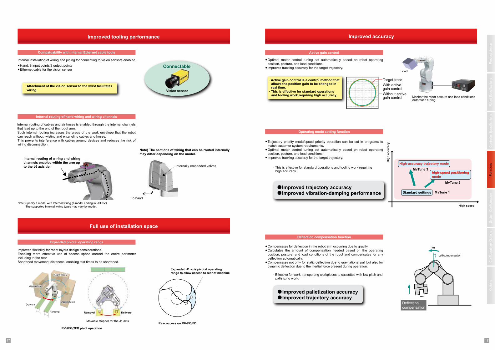
Internal installation of wiring and piping for connecting to vision sensors enabled.
●●
Hand: 8 input points/8 output points
Ethernet cable for the vision sensor
Compatuability with internal Ethernet cable tools
Internal routing of hand wiring and wiring channels
Expanded pivotal operating range
To hand
Internally embedded valves
Vision sensor
RV-2FQ/2FD pivot operation
Removal Delivery
Movable stopper for the J1 axis
Expanded J1 axis pivotal operating
range to allow access to rear of machine
Rear access on RH-FQ/FD
· Attachment of the vision sensor to the wrist facilitates
wiring.
Connectable
Internal routing of wiring and wiring
channels enabled within the arm up
to the J6 axis tip.
Note) The sections of wiring that can be routed internally
may differ depending on the model.
Internal routing of cables and air hoses is enabled through the internal channels
that lead up to the end of the robot arm.
Such internal routing increases the areas of the work envelope that the robot
can reach without twisting and entangling cables and hoses.
This prevents interference with cables around devices and reduces the risk of
wiring disconnection.
Improved flexibility for robot layout design considerations.
Enabling more effective use of access space around the entire perimeter
including to the rear.
Shortened movement distances, enabling takt times to be shortened.
Apparatus 2
Apparatus 3Delivery
Removal
Apparatus 1
Note: Specify a model with Internal wiring (a model ending in ‘-SHxx’).
The supported Internal wiring types may vary by model.
1 219 20
Pro
duct
Lin
eup
Robot
Specific
ations
Fu
nctio
ns
Options
Syste
m C
on
fig
ura
tio
nC
onfigura
tions O
ptio
ns
Co
ntr
olle
r S
pecific
ations
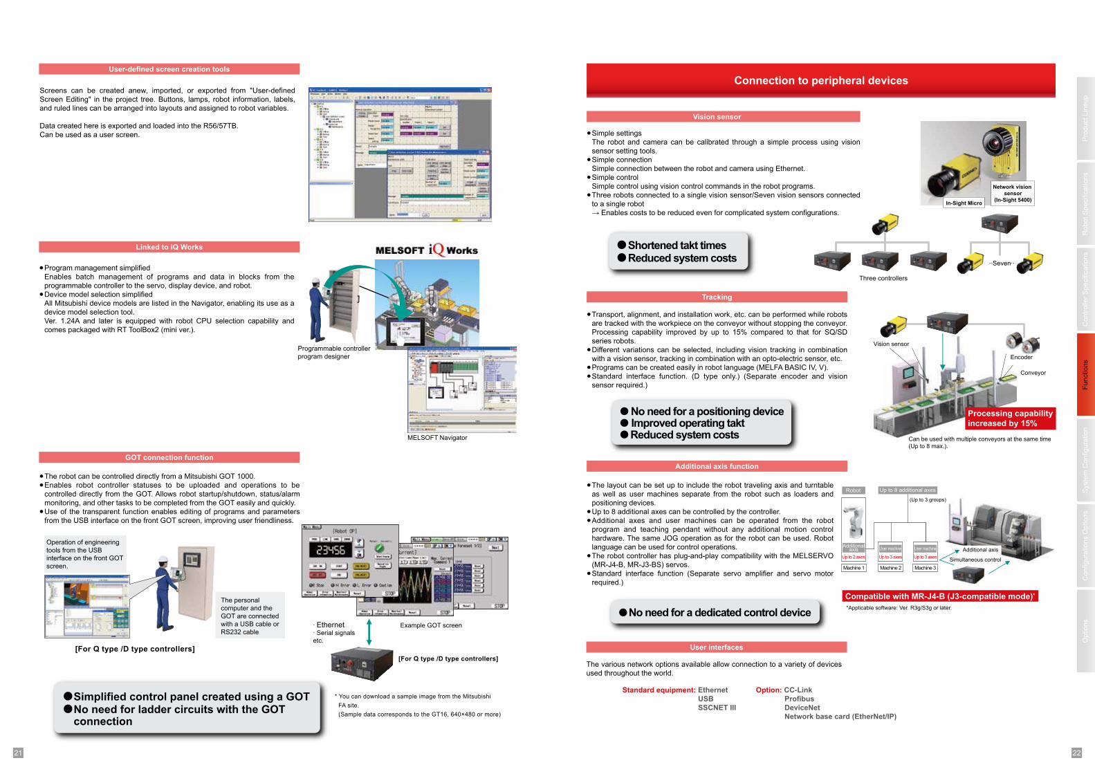
Enhanced RT ToolBox2 (PC software) graphic display function
allowing setting parameters to be displayed visually. Visual
confirmation using this function helps to proactively prevent
setting errors.
Display of teaching positions and trajectories of end points helps to
facilitate confirmation tasks during programming or simulations.
Improved user friendliness
Enables the robot to be controlled from the robot control screen using the
same functions as on the operating panel of the robot controller.
Monitoring screens can be set up individually to match the needs of user
debugging conditions.
●
●
Hands can be created as combinations of basic diagrams on the
Hand Editing screen and then attached to the robot. Allows the
relationships between the hand, workpiece, and peripheral
devices to be checked with a single glance during simulation.
Standard 3D polygonal models can be imported into the program.
Environmental models created using 3DCAD can be displayed on
the screen, allowing operators to confirm the positional relationship
between the robot and peripheral devices during simulation.
(Applicable 3D data file formats: STL, OBJ)
Simple automatic operation from the teaching box
Enhanced RT ToolBox 2 visual functions
Robot control screen (R56TB)
Enables automatic operation of servo power on/off, startup,
shutdown, reset, program selection, and other operations.
Display of trajectories
Display of user-defined regions/freedom-limited planes
Display of selected positions
Display of selected position data
Attachment of a hand created in RT ToolBox2 Example of a system environment screen from an imported model
· Enabled for R32B/R33TB and R56TB/R57TB.
Adaptation to operation
The robot can be made to pass through the singular point, unlike with previous
robot models. This allows for greater flexibility in the layout of robots and
surrounding areas.
Teaching operations can be performed more easily as there is no longer any
need to cancel operations due to the presence of the singular point.
●
●
This function reduces the rigidity of the robot arm and tracks external forces.
The robot itself is equipped with a compliance function, which makes special
hands and sensors unnecessary.
This allows the amount of force generated through interference during
chucking and workpiece insertion to be reduced and external movement
copying forces to be controlled.
●
●
Tool settings for the tool coordinate system can be set by attaching the tool and
using three to eight of the same teaching points.
Enables settings to be made for the actual tool including errors introduced
when the tool was made and other data without needing to calculate values
from the tool diagram.
Simplified tool length setting
Function for passing through the singular point
Orthogonal compliance control
Set using three to eight
teaching points
P2
P1
Movement direction
P2
J4 axis rotation
Posture at start point
Posture at target position
Insertion direction or normal
control direction
Copy plane
Tool coordinate system
Robot hand
Positioning device
+X+Y
+Z
· The compliance direction can be set arbitrarily using the robot
coordinate system, the tool coordinate system, etc.
· This is useful in protecting against workpiece interference and cutting
down on stoppage.
Reduced tooling costsShortened line stop timesShortened startup times
In moving from P1→P2, if the robot is passing the singular
point (J5 axis = 0°) or a location
in the vicinity at a constant
posture, the J4 axis on the robot
will rotate at high speed and be
unable to pass through it.
What a singular point is: There is an unlimited number of angles at which the J4 and J6 axes can be set such that the angle of the J5 axis is 0° when linear interpolation operations are performed using position data from a joint coordinate system. This point is the singular point and is the point at which the robot cannot be operated at an assigned position and posture under normal conditions. The position at which this occurs is referred to as a singular point.
Tool length
1 221 22
Pro
duct
Lin
eup
Robot
Specific
ations
Fu
nctio
ns
Options
Syste
m C
on
fig
ura
tio
nC
onfigura
tions O
ptio
ns
Co
ntr
olle
r S
pecific
ations
●
●●
●
●
The layout can be set up to include the robot traveling axis and turntable
as well as user machines separate from the robot such as loaders and
positioning devices.
Up to 8 additional axes can be controlled by the controller.
Additional axes and user machines can be operated from the robot
program and teaching pendant without any additional motion control
hardware. The same JOG operation as for the robot can be used. Robot
language can be used for control operations.
The robot controller has plug-and-play compatibility with the MELSERVO
(MR-J4-B, MR-J3-BS) servos.
Standard interface function (Separate servo amplifier and servo motor
required.)
The various network options available allow connection to a variety of devices
used throughout the world.
●
●
●●
Transport, alignment, and installation work, etc. can be performed while robots
are tracked with the workpiece on the conveyor without stopping the conveyor.
Processing capability improved by up to 15% compared to that for SQ/SD
series robots.
Different variations can be selected, including vision tracking in combination
with a vision sensor, tracking in combination with an opto-electric sensor, etc.
Programs can be created easily in robot language (MELFA BASIC IV, V).
Standard interface function. (D type only.) (Separate encoder and vision
sensor required.)
Connection to peripheral devices
Simple settings
The robot and camera can be calibrated through a simple process using vision
sensor setting tools.
Simple connection
Simple connection between the robot and camera using Ethernet.
Simple control
Simple control using vision control commands in the robot programs.
Three robots connected to a single vision sensor/Seven vision sensors connected
to a single robot
→ Enables costs to be reduced even for complicated system configurations.
●
●
●
●
Vision sensor
Tracking
Additional axis function
User interfaces
··Seven··
Three controllers
In-Sight Micro
Network vision
sensor
(In-Sight 5400)
Vision sensor
Encoder
Conveyor
Can be used with multiple conveyors at the same time
(Up to 8 max.).
Processing capability
increased by 15%
Additional axis
Simultaneous control
Additionalaxis
Up to 2 axes
User machine
Up to 3 axes
Machine 1 Machine 2 Machine 3
Robot Up to 8 additional axes
(Up to 3 groups)
Compatible with MR-J4-B (J3-compatible mode)*
Standard equipment: Ethernet
USB
SSCNET III
Option: CC-Link
Profibus
DeviceNet
Network base card (EtherNet/IP)
User machine
Up to 3 axes
No need for a dedicated control device
Reduced system costs
Reduced system costs
Shortened takt times
No need for a positioning deviceImproved operating takt
*Applicable software: Ver. R3g/S3g or later.
Program management simplified
Enables batch management of programs and data in blocks from the
programmable controller to the servo, display device, and robot.
Device model selection simplified
All Mitsubishi device models are listed in the Navigator, enabling its use as a
device model selection tool.
Ver. 1.24A and later is equipped with robot CPU selection capability and
comes packaged with RT ToolBox2 (mini ver.).
●
●
●●
●
The robot can be controlled directly from a Mitsubishi GOT 1000.
Enables robot controller statuses to be uploaded and operations to be
controlled directly from the GOT. Allows robot startup/shutdown, status/alarm
monitoring, and other tasks to be completed from the GOT easily and quickly.
Use of the transparent function enables editing of programs and parameters
from the USB interface on the front GOT screen, improving user friendliness.
Screens can be created anew, imported, or exported from "User-defined
Screen Editing" in the project tree. Buttons, lamps, robot information, labels,
and ruled lines can be arranged into layouts and assigned to robot variables.
Data created here is exported and loaded into the R56/57TB.
Can be used as a user screen.
User-defined screen creation tools
Linked to iQ Works
GOT connection function
MELSOFT Navigator
[For Q type /D type controllers]
The personal
computer and the
GOT are connected
with a USB cable or
RS232 cable
Operation of engineering
tools from the USB
interface on the front GOT
screen.
· Ethernet· Serial signals
etc.
Example GOT screen
[For Q type /D type controllers]
* You can download a sample image from the Mitsubishi
FA site.
(Sample data corresponds to the GT16, 640×480 or more)
Programmable controller
program designer
Simplified control panel created using a GOTNo need for ladder circuits with the GOT connection
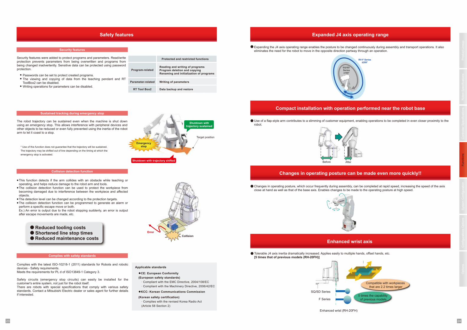
1 223 24
Pro
duct
Lin
eup
Robot
Specific
ations
Fu
nctio
ns
Options
Syste
m C
on
fig
ura
tio
nC
onfigura
tions O
ptio
ns
Co
ntr
olle
r S
pecific
ations
Expanded J4 axis operating range
Expanding the J4 axis operating range enables the posture to be changed continuously during assembly and transport operations. It also
eliminates the need for the robot to move in the opposite direction partway through an operation.
Use of a flap-style arm contributes to a slimming of customer equipment, enabling operations to be completed in even closer proximity to the
robot.
Changes in operating posture, which occur frequently during assembly, can be completed at rapid speed, increasing the speed of the axis
close at hand as well as that of the base axis. Enables changes to be made to the operating posture at high speed.
Enhanced wrist axis
Tolerable J4 axis inertia dramatically increased. Applies easily to multiple hands, offset hands, etc.
[5 times that of previous models (RH-20FH)]
Compact installation with operation performed near the robot base
Changes in operating posture can be made even more quickly!!
SQ/SD Series
F Series
Compatible with workpieces
that are 2.2 times larger
5 times the capability
of previous models
Enhanced wrist (RH-20FH)
Before After
SQ/SD
Series
±160°
SQ/SD
Series
±160°
RV-F Series
±200°
RV-F Series
±200°
The robot trajectory can be sustained even when the machine is shut down
using an emergency stop. This allows interference with peripheral devices and
other objects to be reduced or even fully prevented using the inertia of the robot
arm to let it coast to a stop.
Complies with the latest ISO-10218-1 (2011) standards for Robots and robotic
devices - Safety requirements.
Meets the requirements for PL d of ISO13849-1 Category 3.
Safety circuits (emergency stop circuits) can easily be installed for the
customer's entire system, not just for the robot itself.
There are robots with special specifications that comply with various safety
standards. Contact a Mitsubishi Electric dealer or sales agent for further details
if interested.
●
●
●●
This function detects if the arm collides with an obstacle while teaching or
operating, and helps reduce damage to the robot arm and tools.
The collision detection function can be used to protect the workpiece from
becoming damaged due to interference between the workpiece and affected
objects.
The detection level can be changed according to the protection targets.
The collision detection function can be programmed to generate an alarm or
perform a specific escape move or both.
Ex.) An error is output due to the robot stopping suddenly, an error is output
after escape movements are made, etc.
Safety features
●●
●
Security features were added to protect programs and parameters. Read/write
protection prevents parameters from being overwritten and programs from
being changed inadvertently. Sensitive data can be protected using password
protection.
Passwords can be set to protect created programs.
The viewing and copying of data from the teaching pendant and RT
ToolBox2 can be disabled.
Writing operations for parameters can be disabled.
Security features
Sustained tracking during emergency stop
Collision detection function
Complies with safety standards
Protected and restricted functions
Program-relatedReading and writing of programs
Program deletion and copying
Renaming and initialization of programs
Parameter-related Writing of parameters
RT Tool Box2 Data backup and restore
* Use of this function does not guarantee that the trajectory will be sustained.
The trajectory may be shifted out of line depending on the timing at which the
emergency stop is activated.
Error
Applicable standards
●CE: European Conformity
(European safety standards)
· Compliant with the EMC Directive, 2004/108/EC
· Compliant with the Machinery Directive, 2006/42/EC
●KCC: Korean Communications Commission
(Korean safety certification)
· Complies with the revised Korea Radio Act
(Article 58 Section 2)
Collision
Reduced tooling costsShortened line stop timesReduced maintenance costs
Emergencystop
Shutdown withtrajectory sustained
Target position
Shutdown with trajectory shifted
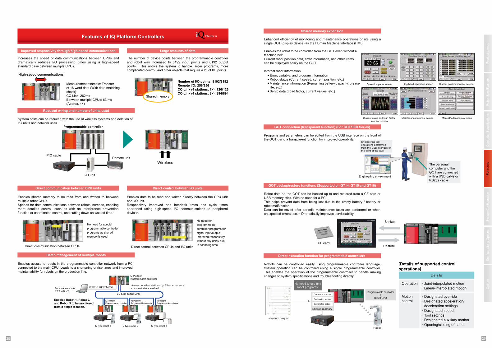
1 225 26
Pro
duct
Lin
eup
Robot
Specific
ations
Fu
nctio
ns
Options
Syste
m C
on
fig
ura
tio
nC
onfigura
tions O
ptio
ns
Co
ntr
olle
r S
pecific
ations
Programs and parameters can be edited from the USB interface on the front of
the GOT using a transparent function for improved operability.
Robot data on the GOT can be backed up to and restored from a CF card or
USB memory stick. With no need for a PC.
This helps prevent data from being lost due to the empty battery / battery or
robot malfunction.
Data can be saved after periodic maintenance tasks are performed or when
unexpected errors occur. Dramatically improves serviceability.
Robots can be controlled easily using programmable controller language.
System operation can be controlled using a single programmable controller.
This enables the operation of the programmable controller to handle making
changes to system specifications and troubleshooting directly.
Enhanced efficiency of monitoring and maintenance operations onsite using a
single GOT (display device) as the Human Machine Interface (HMI).
Enables the robot to be controlled from the GOT even without a
teaching box.
Current robot position data, error information, and other items
can be displayed easily on the GOT.
Internal robot information
●●●
●
Error, variable, and program information
Robot status (Current speed, current position, etc.)
Maintenance information (Remaining battery capacity, grease
life, etc.)
Servo data (Load factor, current values, etc.)
Shared memory expansion
GOT connection (transparent function) (For GOT1000 Series)
GOT backup/restore functions (Supported on GT14, GT15 and GT16)
Direct execution function for programmable controllers
Backup
Restore
Maintenance forecast screen
Current position monitor screen Jog/hand operation screenOperation panel screen
Engineering tool
operations performed
from the USB interface on
the front of the GOT
Engineering environment
[Details of supported control
operations]
Details
Operation
Motion
control
· Joint-interpolated motion
· Linear-interpolated motion
· Designated override
· Designated acceleration/
deceleration settings
· Designated speed
· Tool settings
· Designated auxiliary motion
· Opening/closing of hand
No need to use any
robot programs!!
Command number
Destination number
Designated option
Shared memory
Robot
Programmable controller
+
Robot CPU
sequence program
Current value and load factor
monitor screen
Manual/video display menu
CF card
The personal
computer and the
GOT are connected
with a USB cable or
RS232 cable
Enables access to robots in the programmable controller network from a PC
connected to the main CPU. Leads to a shortening of rise times and improved
maintainability for robots on the production line.
Features of IQ Platform Controllers
System costs can be reduced with the use of wireless systems and deletion of
I/O units and network units.
Enables shared memory to be read from and written to between
multiple robot CPUs.
Speeds for data communications between robots increase, enabling
more detailed control, such as with an interference prevention
function or coordinated control, and cutting down on wasted time.
Enables data to be read and written directly between the CPU unit
and I/O unit.
Responsivity improved and interlock times and cycle times
shortened using high-speed I/O communications to peripheral
devices.
Increases the speed of data communications between CPUs and
dramatically reduces I/O processing times using a high-speed
standard base between multiple CPUs.
The number of device points between the programmable controller
and robot was increased to 8192 input points and 8192 output
points. This allows the system to handle larger programs, more
complicated control, and other objects that require a lot of I/O points.
Improved responsivity through high-speed communications Large amounts of data
Direct communication between CPU units Direct control between I/O units
Reduced wiring and number of units used
Batch management of multiple robots
Programmable controller
I/O unit
Personal computer
RT ToolBox2
iQ Platform
Programmable controller
USB/RS-232/Ethernet
iQ Platform
Programmable controller
iQ Platform
Programmable controller
iQ Platform
Programmable controller
Shared memory
PIO cableRemote unit
Wireless
High-speed communications
CC-Link-IE/CC-Link
Access to other stations by Ethernet or serial
communications enabled
Enables Robot 1, Robot 2,
and Robot 3 to be monitored
from a single location.
Q type robot 1 Q type robot 2 Q type robot 3
Direct communication between CPUs
No need for special
programmable controller
programs as shared
memory is used.
Direct control between CPUs and I/O units
No need for
programmable
controller programs for
signal input/output
Improved responsivity
without any delay due
to scanning time
Measurement example: Transfer
of 16-word data (With data matching
check)
CC-Link: 262ms
Between multiple CPUs: 63 ms
(Approx. 4×)
Number of I/O points: 8192/8192
Remote I/O: 256/256
CC-Link (4 stations, 1×): 126/126
CC-Link (4 stations, 8×): 894/894
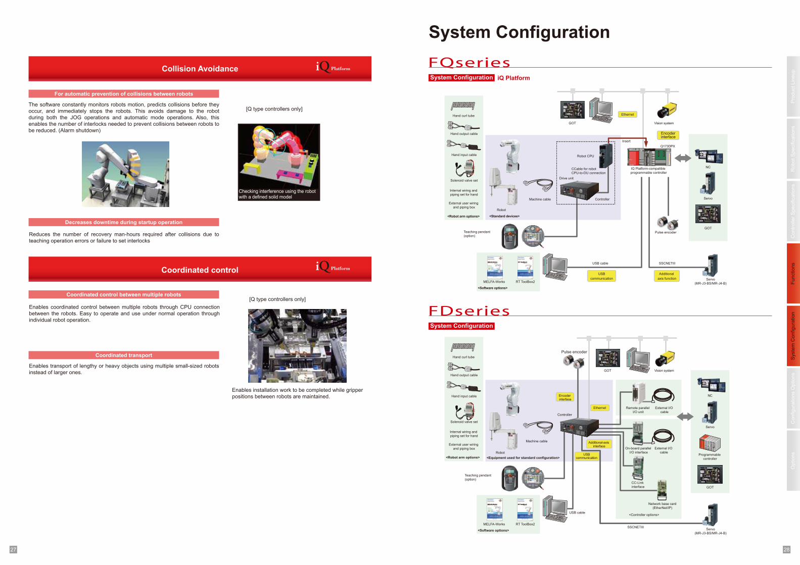
1 227 28
Pro
duct
Lin
eup
Robot
Specific
ations
Fu
nctio
ns
Options
Syste
m C
on
fig
ura
tio
nC
onfigura
tions O
ptio
ns
Co
ntr
olle
r S
pecific
ations
Internal wiring and
piping set for hand
External user wiring
and piping box
Internal wiring and
piping set for hand
External user wiring
and piping box
PULL
MITSUBISHI
M EL SECQ6xP
POWER Q01CPU
RUNERR
PULL▼
▼RS-232
Q41X
RUNSTOP
Q172DRCPU
SW
EMI
DIS
PLA
Y I
/FT
U I
/FCN
1C
N2
System Configuration
System Configuration
System Configuration iQ Platform
FQseries
FDseries
Drive unit
Robot CPU
Controller
Robot
Pulse encoder
Servo
(MR-J3-BS/MR-J4-B)
ServoMachine cable
USB cable
Ethernet
USB
communication
Additional
axis function
SSCNETIII
GOT
Teaching pendant
(option)
Robot
Controller
Machine cable
Ethernet
USBcommunication
Teaching pendant
(option)
Servo
Servo
(MR-J3-BS/MR-J4-B)
Pulse encoder
GOT
GOT
Programmable
controller
NC
CCable for robot
CPU-to-DU connection
GOT
NC
Hand curl tube
Hand input cable
Solenoid valve set
Hand output cable
Hand curl tube
Hand input cable
Solenoid valve set
Hand output cable
MELFA-Works RT ToolBox2
MELFA-Works RT ToolBox2
<Standard devices>
<Equipment used for standard configuration>
External I/O
cable
Remote parallel
I/O unit
On-board parallel
I/O interface
CC-Link
interface
External I/O
cable
<Robot arm options>
Insert
IQ Platform-compatible
programmable controller
<Software options>
Encoder interface
Q173DPX
Vision system
Encoder interface
Additional-axis interface
Vision system
Network base card
(EtherNet/IP)
<Controller options>
<Robot arm options>
<Software options>
USB cable
SSCNETIII
Coordinated control
Reduces the number of recovery man-hours required after collisions due to
teaching operation errors or failure to set interlocks
Enables coordinated control between multiple robots through CPU connection
between the robots. Easy to operate and use under normal operation through
individual robot operation.
Enables transport of lengthy or heavy objects using multiple small-sized robots
instead of larger ones.
Collision Avoidance
For automatic prevention of collisions between robots
Decreases downtime during startup operation
Coordinated control between multiple robots
Coordinated transport
The software constantly monitors robots motion, predicts collisions before they
occur, and immediately stops the robots. This avoids damage to the robot
during both the JOG operations and automatic mode operations. Also, this
enables the number of interlocks needed to prevent collisions between robots to
be reduced. (Alarm shutdown)
[Q type controllers only]
[Q type controllers only]
Checking interference using the robot with a defined solid model
Enables installation work to be completed while gripper
positions between robots are maintained.
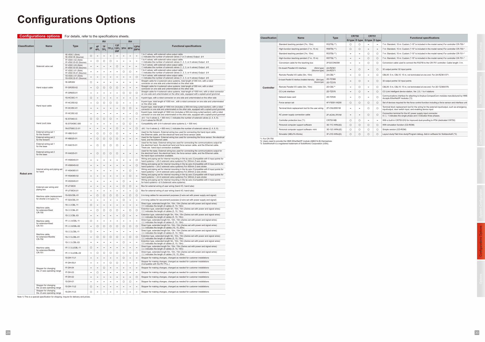
1 229 30
Pro
duct
Lin
eup
Robot
Specific
ations
Fu
nctio
ns
Options
Syste
m C
on
fig
ura
tio
nC
onfigura
tions O
ptio
ns
Co
ntr
olle
r S
pecific
ations
Configurations Options
Configurations options
Classification Name Type
RV RH
Functional specifications
1E-VD0□ (Sink)
1E-VD0□E (Source)
6FH3FH2F12FH20FH
7F7FL
4F4FL
1 to 2 valves, with solenoid valve output cable.
□ indicates the number of solenoid valves (1 or 2 valves) Output: φ4
Wiring and piping set for internal mounting in the tip axis (Compatible with 8 input points for
hand systems + φ6-2 solenoid valve systems) For 350mm Z-axis stroke
Wiring and piping set for internal mounting in the tip axis (Compatible with 8 input points for
hand systems + φ6-2 solenoid valve systems) For 450mm Z-axis stroke
Wiring and piping set for internal mounting in the tip axis (Compatible with 8 input points for
hand systems + φ4-4 solenoid valve systems) For 200mm Z-axis stroke
Wiring and piping set for internal mounting in the tip axis (Compatible with 8 input points for
hand systems + φ4-4 solenoid valve systems) For 340mm Z-axis stroke
Box for external wiring of user wiring (hand I/O, hand tube)
Box for external wiring of user wiring (hand I/O, hand tube)
2-m-long cables for securement purposes (2-wire set with power supply and signal)
2-m-long cables for securement purposes (2-wire set with power supply and signal)
Direct type, extended length 5m, 10m, 15m (2wires set with power and signal wires)
□□ indicates the length of cables (5, 10, 15m)
Extention type, extended length 5m, 10m, 15m (2wires set with power and signal wires)
□□ indicates the length of cables (5, 10, 15m)
Extention type, extended length 5m, 10m, 15m (2wires set with power and signal wires)
□□ indicates the length of cables (5, 10, 15m)
Extention type, extended length 5m, 10m, 15m (2wires set with power and signal wires)
□□ indicates the length of cables (5, 10, 15m)
Direct type, extended length 5m, 10m, 15m (2wires set with power and signal wires)
□□ indicates the length of cables (5, 10, 15m)
Direct type, extended length 5m, 10m, 15m (2wires set with power and signal wires)
□□ indicates the length of cables (10, 15, 20m)
Stopper for making changes, changed as needed for customer installations
Stopper for making changes, changed as needed for customer installations
Hand output cable
Hand input cable
Hand (curl) tube
For details, refer to the specifications sheets.
--1F-VD0□-02 (Sink)
1F-VD0□E-02 (Source) --
1F-GR60S-01 ○○--1S-HC30C-11 --1F-HC35S-02 --
1F-HS604S-01
Internal wiring and piping set
for hand
○-
1F-HS604S-02 ○-1F-HS408S-01 -○1F-HS408S-02 -○1F-HS304S-01
External user wiring and
piping box
Machine cable (replacement
for shorter 2-m type) (*1)
--1F-UT-BOX -○1F-UT-BOX-01 ○-1S-02UCBL-01 ○○1F-02UCBL-01 -1S-□□CBL-11
Machine cable,
for extension/fixed
CR-750
Machine cable,
for extension/flexible
CR-750
--1S-□□CBL-01 ○○1S-□□CBL-03 --
1S-□□LCBL-03 --
1F-□□LUCBL-11 --
1F-□□LUCBL-02 ○○
1F-DH-02
Stopper for changing
the J1-axis operating range
○-1S-DH-01 -○
-
-
○-
-
-
○--
-
-
-
○○--○-
-
○
○-
○
-○
Robot arm
Classification Name TypeCR750 CR751
Functional specifications
R32TB(-**)Standard teaching pendant (7m, 15m) 7 m: Standard, 15 m: Custom ("-15" is included in the model name) For controller CR-750-*○ -R56TB(-**)High-function teaching pendant (7 m, 15 m)
High-function teaching pendant (7 m, 15 m)
7 m: Standard, 15 m: Custom ("-15" is included in the model name) For controller CR-750-*○ -
2D-TZ368
2D-TZ378
Standard teaching pendant (7m, 15m)
- ○
On-board Parallel I/O interface (Installed internally) (Sink type)
(Source type) - -
Remote Parallel I/O cable (5m, 15m)
Remote Parallel I/O cable (5m, 15m) 2D-CBL**
CC-Link interface CC-Link Intelligent device station, Ver. 2.0, 1 to 4 stations
- -2D-TZ576
32 output points/ 32 input points
- -
2D-TZ535Network base cardCommunications interface for attaching to Anybus-CompactCom modules manufactured by HMS
Accepts EtherNet/IP modules (*2)- -
Force sensor set ○ ○Terminal block replacement tool for the user wiring
Terminal block replacement tool for the wiring for the external input/output, such as emergency
input/output, door switch input, and enabling device input- ○2F-CNUSR01M
Personal computer support software With simulation function (CD-ROM) 3D-11C-WINJ(E)
Personal computer support software -mini Simple version (CD-ROM)
○ ○3D-12C-WINJ(E) ○ ○3F-21D-WINJ(E)Simulator (MELFA-Works) Layout study/Takt time study/Program debug. Add-in software for Solidworks® (*3) ○ ○
Controller
*1: For CR-750
*2: Users need to provide the HMS EtherNet/IP module (AB6314-B) themselves.
*3: SolidWorks® is a registered trademark of SolidWorks Corporation (USA).
Note 1) This is a special specification for shipping. Inquire for delivery and prices.
2A-RZ361
2A-RZ371
On-board Parallel I/O interface (Sink type)
(Source type) - -
2A-CBL** CBL05: 5 m, CBL15: 15 m, not terminated at one end. For 2A-RZ361/371.
CBL05: 5 m, CBL15: 15 m, not terminated at one end. For 2D-TZ368/378.
-
○○
-
○○○○○-
○○○
○○ -
--
○- ○- ○
○○○○○○
AC power supply connection cableConnection terminal for the AC power supply input connector.
In □, 1 indicates the single phase and 3 indicates three phases.- ○2F-ACIN□P01M - ○
○Controller protection box (*1) With a built-in CR750-D/Q for improved dust-proofing to IP54 (dedicated CR750) CR750-MB ○ -○ -
○○
○○
32 output points/ 32 input points
1E-ST0408C-300
1N-ST060□C-01
-○○
Solenoid valve set
Straight cable for 4-solenoid valve systems, total length of 1050 mm, with a robot connector
on one side and unterminated on the other side, equipped with a splash-proof grommet
Compatibility with φ4-4 solenoid valve systems (L = 300 mm)
Wiring and piping set for internal mounting in the tip axis (Compatible with 4 input points
for hand systems +φ3-2solenoid valve systems)
φ6: 1 to 4 valves (L = 600 mm) □ indicates the number of solenoid valves (2, 4, 6, 8).
4-point type, with a robot connector on one side and unterminated on the other side
8-point type, total length of 1000 mm , with a robot connector on one side and unterminated
on the other side
1 to 4 valves, with solenoid valve output cable.
□ indicates the number of solenoid valves (1, 2, 3, or 4 valves) Output: φ4
Q type D type
7 m: Standard, 15 m: Custom ("-15" is included in the model name) For controller CR-751-*
7 m: Standard, 15 m: Custom ("-15" is included in the model name) For controller CR-751-*
R33TB(-**)
R57TB(-**)
Q type D type
1F-VD0□-01 (Sink)
1F-VD0□E-01 (Source)
1S-VD0□-01 (Sink)
1S-VD0□E-01 (Source)
○ - -
- ○ ○
1 to 4 valves, with solenoid valve output cable.
□ indicates the number of solenoid valves (1, 2, 3, or 4 valves) Output: φ4
1 to 4 valves, with solenoid valve output cable.
□ indicates the number of solenoid valves (1, 2, 3, or 4 valves) Output: φ6
-○○- - -
○--- - -
-
1F-GR35S-02 --○○ - Straight cable for 4-solenoid valve systems, total length of 300 mm, with a robot
connector on one side and unterminated on the other side-
1E-GR35S ---- - Straight cable for 2-solenoid valve systems, total length of 300 mm, with a robot
connector on one side and unterminated on the other side○
--○○○-
-○○---1F-HC35C-018-point type, total length of 1650 mm (includes a 350-mm-long curled section), with a robot
connector on one side and unterminated on the other side, equipped with a splash-proof grommet
○-----1F-HC35C-028-point type, total length of 1800 mm (includes a 350-mm-long curled section), with a robot
connector on one side and unterminated on the other side, equipped with a splash-proof grommet
1E-ST040□C --- φ4: 1 to 4 valves (L = 300 mm) □ indicates the number of solenoid valves (2, 4, 6, 8).
2 or 4 valves for RV-2F. ○○○------
---
---
---
---
---
------○○----
--○○○-
---
---
--○○○-
------
---○○-1F-HB01S-01Used for the forearm. External wiring box used for connecting the hand input cable,
the Ethernet cable, and the electrical hand and force sensor cable.
External wiring set 1
for the forearm
---○○-1F-HB02S-01Used for the forearm. External wiring box used for connecting the force sensor, the electrical
hand, and the Ethernet cable.
External wiring set 2
for the forearm
---○○-1F-HA01S-01
Used for the base. External wiring box used for connecting the communications output for
the electrical hand, the electrical hand and force sensor cable, and the Ethernet cable.
There are hand input connection available.
External wiring set 1
for the base
---○○-1F-HA02S-01
Used for the base. External wiring box used for connecting the communications output for
the electrical hand, the electrical hand, the force sensor cable, and the Ethernet cable.
No hand input connection available.
External wiring set 2
for the base
Stopper for making changes, changed as needed for customer installations1S-DH-11J1
-----Stopper for making changes, changed as needed for customer installations1F-DH-04 ---○--Stopper for making changes, changed as needed for customer installations1F-DH-03 ----○-
Set of devices required for the force control function including a force sensor and interface unit4F-FS001-W200
13F13FL20F
-
-
-
-
○
-
-
-
-
-
--○
-
○-
-
-
--
○-
-
-
○-
-
-
-
○○○
○
○--
7FLL
-
○
-
-
○
-
-
-
-
-
--○
-
○-
-
-
○
--
--
-
-
○-
-
-
○
○○○
○
○--
1F-VD0□-03 (Sink)
1F-VD0□E-03 (Source)
1 to 4 valves, with solenoid valve output cable.
□ indicates the number of solenoid valves (1, 2, 3, or 4 valves) Output: φ6
Stopper for making changes, changed as needed for customer installations
(Compatible with the RV-7FLL.)-1F-DH-05J1
Stopper for making changes, changed as needed for customer installations1S-DH-11J2 -----○ --
Stopper for making changes, changed as needed for customer installations1S-DH-11J3 -----○ --
Stopper for changing
the J2-axis operating range
Stopper for changing
the J3-axis operating range
---- - - ○-
---
--○--- --
2F32CON03MConversion cable for the teaching box - ○- ○ Conversion cable used to connect the R32TB to the CR-751 controller. Cable length: 3 m.
Direct type, extended length 5m, 10m, 15m (2wires set with power and signal wires)
□□ indicates the length of cables (5, 10, 15m)1F-□□UCBL-11 -----○ --
Direct type, extended length 5m, 10m, 15m (2wires set with power and signal wires)
□□ indicates the length of cables (10, 15, 20m)1F-□□UCBL-02 ○○○○○- ○
Direct type, extended length 5m, 10m, 15m (2wires set with power and signal wires)
□□ indicates the length of cables (5, 10, 15m)1S-□□LCBL-11 -----○ --
Extention type, extended length 5m, 10m, 15m (2wires set with power and signal wires)
□□ indicates the length of cables (5, 10, 15m)1S-□□LCBL-01 ○○-○○- ○○
Machine cable,
for extension/fixed
CR-751
Machine cable,
for extension/flexible
CR-751
○
○
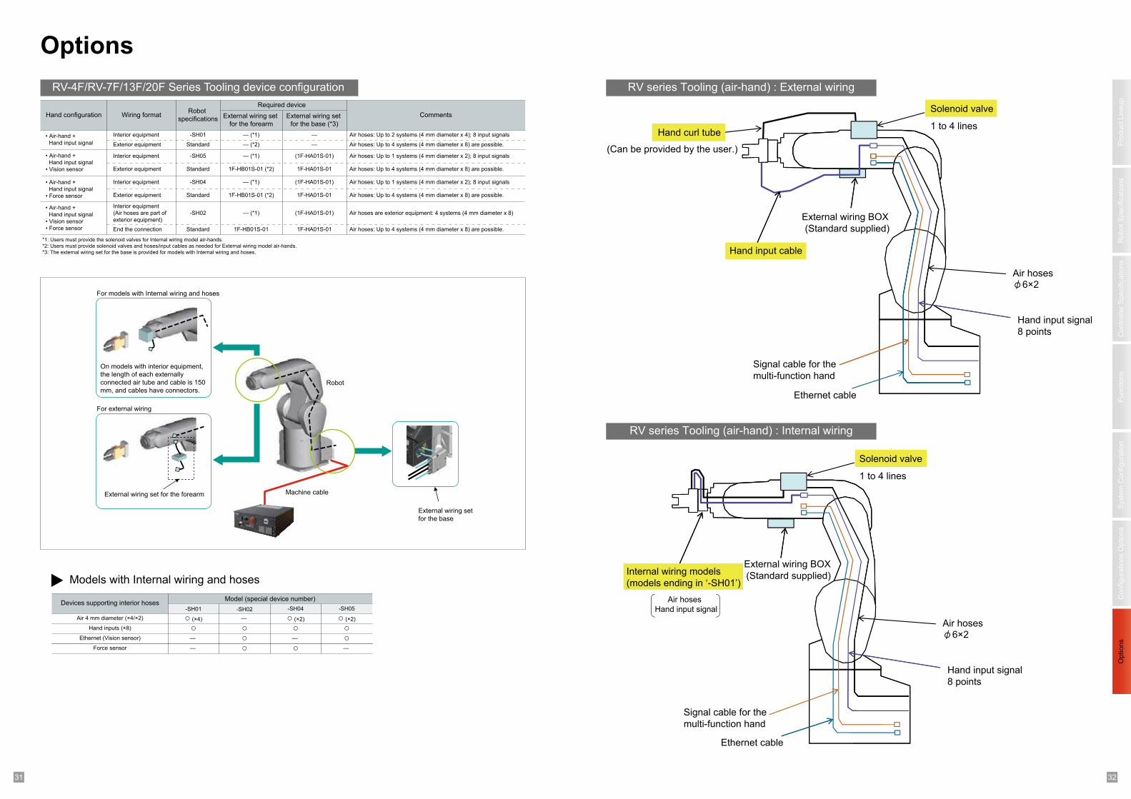
1 231 32
Pro
duct
Lin
eup
Robot
Specific
ations
Fu
nctio
ns
Options
Syste
m C
on
fig
ura
tio
nC
onfigura
tions O
ptio
ns
Co
ntr
olle
r S
pecific
ations
Options
RV series Tooling (air-hand) : External wiring
RV series Tooling (air-hand) : Internal wiring
*1: Users must provide the solenoid valves for Internal wiring model air-hands.
*2: Users must provide solenoid valves and hoses/input cables as needed for External wiring model air-hands.
*3: The external wiring set for the base is provided for models with Internal wiring and hoses.
Hand configuration Wiring format
• Air-hand + Hand input signal
Interior equipment
• Air-hand + Hand input signal
• Vision sensor
• Air-hand + Hand input signal
• Vision sensor• Force sensor
Interior equipment
(Air hoses are part of exterior equipment)
End the connection
Robot
specifications External wiring set
for the forearm
External wiring set
for the base (*3)
Required device
Comments
-SH01
Standard
1F-HB01S-01 (*2)
Air hoses: Up to 2 systems (4 mm diameter x 4); 8 input signals
Exterior equipment
— (*1)
— (*2)
— (*1)
—
— Air hoses: Up to 4 systems (4 mm diameter x 8) are possible.
Interior equipment
Exterior equipment
-SH05
Standard
(1F-HA01S-01)
1F-HA01S-01
• Air-hand + Hand input signal
• Force sensor
Interior equipment
Exterior equipment
Air hoses: Up to 1 systems (4 mm diameter x 2); 8 input signals
Air hoses: Up to 4 systems (4 mm diameter x 8) are possible.
-SH04
Standard
— (*1)
1F-HB01S-01 (*2)
(1F-HA01S-01)
1F-HA01S-01
Air hoses: Up to 1 systems (4 mm diameter x 2); 8 input signals
Air hoses: Up to 4 systems (4 mm diameter x 8) are possible.
-SH02
Standard
— (*1)
1F-HB01S-01
(1F-HA01S-01)
1F-HA01S-01
Air hoses are exterior equipment: 4 systems (4 mm diameter x 8)
Air hoses: Up to 4 systems (4 mm diameter x 8) are possible.
Models with Internal wiring and hoses
Devices supporting interior hosesModel (special device number)
Air 4 mm diameter (×4/×2) ○ (×4)Hand inputs (×8) ○
Ethernet (Vision sensor) —
— Force sensor
-SH01 -SH02 -SH04 -SH05
—
○○○
○ ○○
○—
—
○ (×2) ○ (×2)
Solenoid valve
1 to 4 linesHand curl tube
(Can be provided by the user.)
External wiring BOX
(Standard supplied)
Hand input cable
Air hosesφ6×2
Hand input signal
8 points
Ethernet cable
Signal cable for the
multi-function hand
Solenoid valve
1 to 4 lines
Internal wiring models
(models ending in ‘-SH01’)
External wiring BOX
(Standard supplied)
Air hosesHand input signal
Air hosesφ6×2
Hand input signal
8 points
Ethernet cable
Signal cable for the
multi-function hand
For models with Internal wiring and hoses
For external wiring
Machine cable
External wiring set
for the base
Robot
External wiring set for the forearm
On models with interior equipment,
the length of each externally
connected air tube and cable is 150
mm, and cables have connectors.
RV-4F/RV-7F/13F/20F Series Tooling device configuration
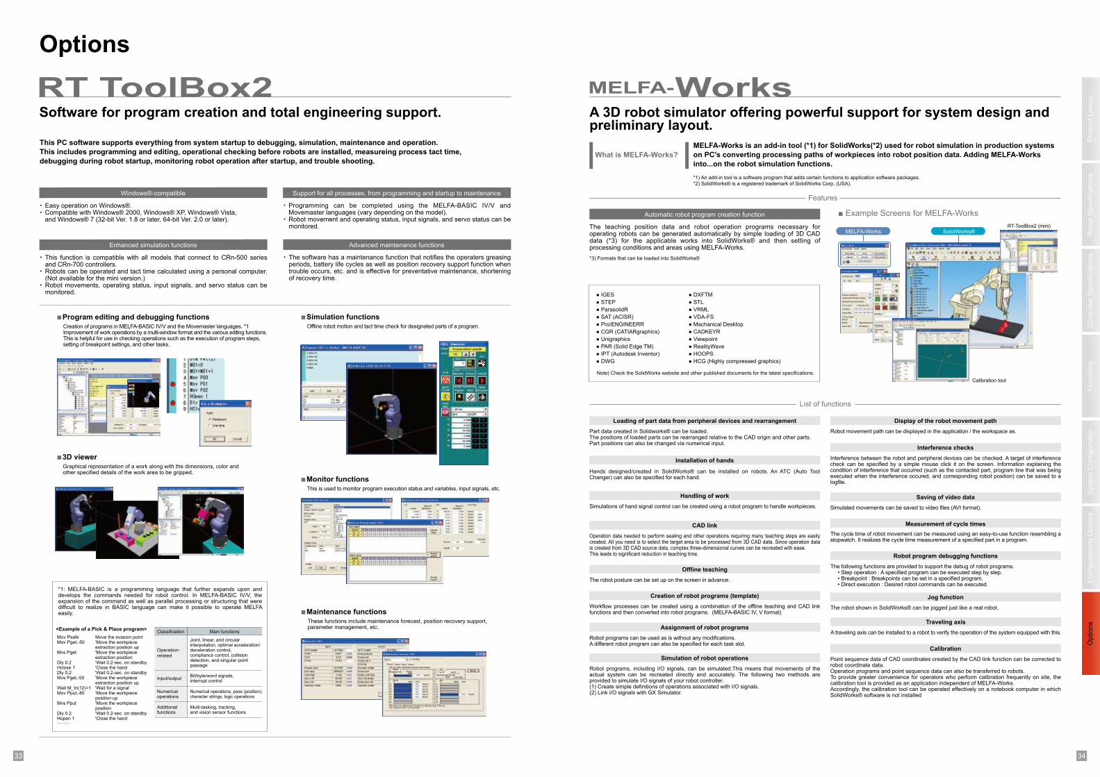
1 233 34
Pro
duct
Lin
eup
Robot
Specific
ations
Fu
nctio
ns
Options
Syste
m C
on
fig
ura
tio
nC
onfigura
tions O
ptio
ns
Co
ntr
olle
r S
pecific
ations
Options
Easy operation on Windows®.Compatible with Windows® 2000, Windows® XP, Windows® Vista, and Windows® 7 (32-bit Ver. 1.8 or later, 64-bit Ver. 2.0 or later).
Windows®-compatible
This function is compatible with all models that connect to CRn-500 series and CRn-700 controllers.Robots can be operated and tact time calculated using a personal computer. (Not available for the mini version.)Robot movements, operating status, input signals, and servo status can be monitored.
Enhanced simulation functions
Programming can be completed using the MELFA-BASIC IV/V and Movemaster languages (vary depending on the model).Robot movement and operating status, input signals, and servo status can be monitored.
Support for all processes, from programming and startup to maintenance
The software has a maintenance function that notifies the operaters greasing periods, battery life cycles as well as position recovery support function when trouble occurs, etc. and is effective for preventative maintenance, shortening of recovery time.
Advanced maintenance functions
■Program editing and debugging functions ■
Software for program creation and total engineering support.
This PC software supports everything from system startup to debugging, simulation, maintenance and operation.
This includes programming and editing, operational checking before robots are installed, measureing process tact time,
debugging during robot startup, monitoring robot operation after startup, and trouble shooting.
RT ToolBox2
Offline robot motion and tact time check for designated parts of a program.Creation of programs in MELFA-BASIC IV/V and the Movemaster languages. *1Improvement of work operations by a multi-window format and the various editing functions. This is helpful for use in checking operations such as the execution of program steps, setting of breakpoint settings, and other tasks.
■
This is used to monitor program execution status and variables, input signals, etc.
These functions include maintenance forecast, position recovery support, parameter management, etc.
■
Simulation functions
3D viewer
Monitor functions
Graphical representation of a work along with the dimensions, color andother specified details of the work area to be gripped.
Maintenance functions
*1: MELFA-BASIC is a programming language that further expands upon and develops the commands needed for robot control. In MELFA-BASIC IV/V, the expansion of the command as well as parallel processing or structuring that were difficult to realize in BASIC language can make it possible to operate MELFA easily.
Additionalfunctions
Input/output
Operation-
related
Classification Main functions
Joint, linear, and circularinterpolation, optimal acceleration/deceleration control,compliance control, collisiondetection, and singular pointpassage
Bit/byte/word signals,interrupt control
Numericaloperations
Numerical operations, pose (position),character strings, logic operations
Multi-tasking, tracking,and vision sensor functions
Move the evasion point'Move the workpiece extraction position up'Move the workpiece extraction position'Wait 0.2-sec. on standby'Close the hand'Wait 0.2-sec. on standby'Move the workpiece extraction position up'Wait for a signal'Move the workpiece position up'Move the workpiece position'Wait 0.2-sec. on standby'Close the hand
Mov PsafeMov Pget,-50
Mvs Pget
Dly 0.2Hclose 1Dly 0.2Mvs Pget,-50
Wait M_In(12)=1Mov Pput,-80
Mvs Pput
Dly 0.2Hopen 1··········
<Example of a Pick & Place program>
MELFA-Works is an add-in tool (*1) for SolidWorks(*2) used for robot simulation in production systems
on PC's converting processing paths of workpieces into robot position data. Adding MELFA-Works
into...on the robot simulation functions.
What is MELFA-Works?
A 3D robot simulator offering powerful support for system design andpreliminary layout.
The teaching position data and robot operation programs necessary for operating robots can be generated automatically by simple loading of 3D CAD data (*3) for the applicable works into SolidWorks® and then setting of processing conditions and areas using MELFA-Works.
Features
Automatic robot program creation function
Part data created in Solidworks® can be loaded.The positions of loaded parts can be rearranged relative to the CAD origin and other parts.Part positions can also be changed via numerical input.
List of functions
Loading of part data from peripheral devices and rearrangement
Robot movement path can be displayed in the application / the workspace as.
Display of the robot movement path
Hands designed/created in SolidWorks® can be installed on robots. An ATC (Auto Tool Changer) can also be specified for each hand.
Interference between the robot and peripheral devices can be checked. A target of interference check can be specified by a simple mouse click it on the screen. Information explaining the condition of interference that occurred (such as the contacted part, program line that was being executed when the interference occured, and corresponding robot position) can be saved to a logfile.
Interference checks
Simulations of hand signal control can be created using a robot program to handle workpieces.
Handling of work
Installation of hands
Simulated movements can be saved to video files (AVI format).
Saving of video data
Operation data needed to perform sealing and other operations requiring many teaching steps are easily created. All you need is to select the target area to be processed from 3D CAD data. Since operation data is created from 3D CAD source data, complex three-dimensional curves can be recreated with ease. This leads to significant reduction in teaching time.
CAD link
The following functions are provided to support the debug of robot programs. • Step operation : A specified program can be executed step by step. • Breakpoint : Breakpoints can be set in a specified program. • Direct execution : Desired robot commands can be executed.
Robot program debugging functions
The cycle time of robot movement can be measured using an easy-to-use function resembling a stopwatch. It realizes the cycle time measurement of a specified part in a program.
Measurement of cycle times
The robot posture can be set up on the screen in advance.
Offline teaching
The robot shown in SolidWorks® can be jogged just like a real robot.
Jog function
Point sequence data of CAD coordinates created by the CAD link function can be corrected to robot coordinate data. Operation programs and point sequence data can also be transferred to robots.To provide greater convenience for operators who perform calibration frequently on site, the calibration tool is provided as an application independent of MELFA-Works.Accordingly, the calibration tool can be operated effectively on a notebook computer in which SolidWorks® software is not installed
Calibration
Workflow processes can be created using a combination of the offline teaching and CAD link functions and then converted into robot programs. (MELFA-BASIC IV, V format)
Creation of robot programs (template)
A traveling axis can be installed to a robot to verify the operation of the system equipped with this.
Traveling axis
Robot programs can be used as is without any modifications.A different robot program can also be specified for each task slot.
Assignment of robot programs
Robot programs, including I/O signals, can be simulated.This means that movements of the actual system can be recreated directly and accurately. The following two methods are provided to simulate I/O signals of your robot controller.(1) Create simple definitions of operations associated with I/O signals.(2) Link I/O signals with GX Simulator.
Simulation of robot operations
*1) An add-in tool is a software program that adds certain functions to application software packages.
*2) SolidWorks® is a registered trademark of SolidWorks Corp, (USA).
*3) Formats that can be loaded into SolidWorks®
Note) Check the SolidWorks website and other published documents for the latest specifications.
Calibration tool
RT-ToolBox2 (mini)
● IGES
● STEP
● ParasolidR
● SAT (ACISR)
● Pro/ENGINEERR
● CGR (CATIARgraphics)
● Unigraphics
● PAR (Solid Edge TM)
● IPT (Autodesk Inventor)
● DWG
● DXFTM
● STL
● VRML
● VDA-FS
● Machanical Desktop
● CADKEYR
● Viewpoint
● RealityWave
● HOOPS
● HCG (Highly compressed graphics)
■ Example Screens for MELFA-Works
WorksMELFA-
SolidWorks®MELFA-Works
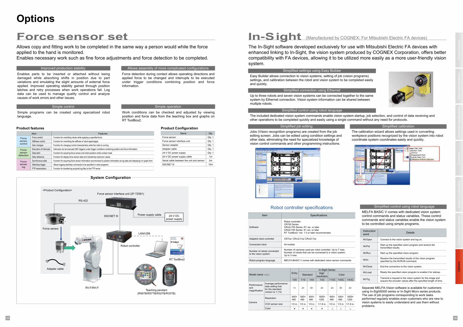
1 235 36
Pro
duct
Lin
eup
Robot
Specific
ations
Fu
nctio
ns
Options
Syste
m C
on
fig
ura
tio
nC
onfigura
tions O
ptio
ns
Co
ntr
olle
r S
pecific
ations
Options
Simplified settings using Easy Builder
Simplified connection using Ethernet
Simplified control using robot language
Simplified calibration
Simplified control using robot language
Simplified job editing
Separate MELFA-Vision software is available for customers
using In-Sight5000 series or In-Sight Micro series products.
The use of job programs corresponding to work tasks
performed regularly enables even customers who are new to
vision systems to easily understand and use them without
problems.
Instruction
wordDetails
NVOpen Connect to the vision system and log on.
NVPstStart up the specified vision program and receive the
transmitted results.
NVRun Start up the specified vision program.
NVInReceive the transmitted results of the vision program
specified by the NVRUN command.
NVClose End the connection to the vision system.
NVLoad Ready the specified vision program to enable it for startup.
NVTrgTransmit a request to the vision system for the image and
acquire the encoder values after the specified length of time.
Item Specifications
Software
Robot controller:
CR750 Series
CRnQ-700 Series: R1 ver. or later
CRnD-700 Series: S1 ver. or later
RT ToolBox2: Ver. 1.0 or later recommended
Adapted robot controller
Connected robot All models
Number of robots connected
to the vision system
Number of cameras used per robot controller: Up to 7 max.
Number of robots that can be connected to a vision system:
Up to 3 max.
Robot program language MELFA-BASIC V comes with dedicated vision sensor commands
Model name -□□□ EntryStandard
High
resolution
143
Color
110C 140C 143C100 110 140
Performance
and
magnification
Average performance
data setting that
for the standard
version to 1 (*2)
1× 2× 5× 4× 2× 5× 4×
Camera
Resolution
CCD sensor size 1/3 in. 1/3 in. 1/3 in. 1/1.8 in. 1/3 in. 1/3 in. 1/1.8 in.
Color × × × × ○ ○ ○
In-SightForce sensor setThe In-Sight software developed exclusively for use with Mitsubishi Electric FA devices with
enhanced linking to In-Sight, the vision system produced by COGNEX Corporation, offers better
compatibility with FA devices, allowing it to be utilized more easily as a more user-friendly vision
system.
Allows copy and fitting work to be completed in the same way a person would while the force
applied to the hand is monitored.
Enables necessary work such as fine force adjustments and force detection to be completed.
(Manufactured by COGNEX: For Mitsubishi Electric FA devices)
Robot controller specifications
CR7xx/ CRnQ-7xx/ CRnD-7xx
In-Sight Series
640×
480
640×
480
640×
480
1600×
1200
640×
480
640×
480
1600×
1200
Jobs (Vision recognition programs) are created from the job
editing screen. Jobs can be edited using condition settings and
other data, eliminating the need for specialized knowledge of
vision control commands and other programming instructions.
The calibration wizard allows settings used in converting
workpiece positions recognized by the vision system into robot
coordinate system coordinates easily and quickly.
MELFA BASIC V comes with dedicated vision system
control commands and status variables. These control
commands and status variables enable the vision system
to be controlled using simple programs.
The included dedicated vision system commands enable vision system startup, job selection, and control of data receiving and
other operations to be completed quickly and easily using a single command without any need for protocols.
Up to three robots and seven vision systems can be connected together to the same
system by Ethernet connection. Vision system information can be shared between
multiple robots.
Easy Builder allows connection to vision systems, setting of job (vision programs)
settings, and calibration between the robot and vision system to be completed easily
and quickly.
Enables parts to be inserted or attached without being
damaged while absorbing shifts in position due to part
variations and emulating the slight amounts of external force
applied. Improved operating stability gained through position
latches and retry processes when work operations fail. Log
data can be used to manage quality control and analyze
causes of work errors and other issues.
Improved production stability
Simple programs can be created using specialized robot
language.
Simple control
Force detection during contact allows operating directions and
applied force to be changed and interrupts to be executed
under trigger conditions combining position and force
information.
Allows assembly of more complicated configurations
Work conditions can be checked and adjusted by viewing
position and force data from the teaching box and graphs on
RT ToolBox2.
Simple operation
Name Qty.
Qty. 1
Qty. 1
Qty. 1
Qty. 1
Qty. 1
1m
5m
10m
Force sensor
Force sensor interface unit
Sensor adapter
Adapter cable
24-V DC power supply
24-V DC power supply cable
Serial cable between the unit and sensor
SSCNET III
FeaturesItem
Forcesensorcontrol
Force control
Stiffness control
Gain changes
Execution of interrupts
Data latch
Data reference
Synchronous data
Start/stop trigger
FTP transmission
Function for controlling robots while applying a specified force
Function for controlling the stiffness of robot appendages
Function for changing control characteristics while the robot is running
Interrupts can be executed (MO triggers) under trigger conditions combining position and force information.
Function for acquiring force sensor and robot positions while contact made
Function for display force sensor data and maintaining maximum values
Function for acquiring force sensor information synchronized to position infromation as log data and displaying it in graph form
Allows logging start/stop commands to be specified in robot programs
Function for transferring acquired log files to the FTP server
Forcesensor
detection
Forcesensor
log
Product ConfigurationProduct features
Teaching pendant
(R56TB/R57TB/R32TB/R33TB)
RV-F/RH-F
RT ToolBox2
Power supply cable
System Configuration
Robot controller
SSCNET III
RS-422
Force sensor
Adapter cable
LAN/USB
<Product Configuration>
24-V DCpower supply
Force sensor interface unit (2F-TZ561)

1 237 38
MEMO MEMO