naval postgraduate school - defense technical · pdf filea. installing oracle database 12c on...
TRANSCRIPT

NAVAL POSTGRADUATE
SCHOOL
MONTEREY, CALIFORNIA
THESIS
Approved for public release; distribution is unlimited
A FRAMEWORK FOR FAULT TOLERANCE IN VIRTUALIZED SERVERS
by
Kadir Deniz Elmas
June 2016
Thesis Advisor: Man-Tak Shing Co-Advisor: Arijit Das

THIS PAGE INTENTIONALLY LEFT BLANK
i
REPORT DOCUMENTATION PAGE Form Approved OMB No. 0704–0188
Public reporting burden for this collection of information is estimated to average 1 hour per response, including the time for reviewing instruction, searching existing data sources, gathering and maintaining the data needed, and completing and reviewing the collection of information. Send comments regarding this burden estimate or any other aspect of this collection of information, including suggestions for reducing this burden, to Washington headquarters Services, Directorate for Information Operations and Reports, 1215 Jefferson Davis Highway, Suite 1204, Arlington, VA 22202-4302, and to the Office of Management and Budget, Paperwork Reduction Project (0704-0188) Washington, DC 20503.
1. AGENCY USE ONLY (Leave blank)
2. REPORT DATE June 2016
3. REPORT TYPE AND DATES COVERED Master’s thesis
4. TITLE AND SUBTITLE A FRAMEWORK FOR FAULT TOLERANCE IN VIRTUALIZED SERVERS
5. FUNDING NUMBERS
6. AUTHOR(S) Kadir Deniz Elmas
7. PERFORMING ORGANIZATION NAME(S) AND ADDRESS(ES)Naval Postgraduate School Monterey, CA 93943-5000
8. PERFORMING ORGANIZATION REPORT NUMBER
9. SPONSORING /MONITORING AGENCY NAME(S) AND ADDRESS(ES)
N/A
10. SPONSORING / MONITORING AGENCY REPORT NUMBER
11. SUPPLEMENTARY NOTES The views expressed in this thesis are those of the author and do not reflect the official policy or position of the Department of Defense or the U.S. Government. IRB Protocol number ____N/A____.
12a. DISTRIBUTION / AVAILABILITY STATEMENT Approved for public release; distribution is unlimited
12b. DISTRIBUTION CODE
13. ABSTRACT (maximum 200 words)
In modern naval platforms, most of the critical operations are done with the help of automated systems. Specifically, operational decisions and actions are finalized using command and control systems (C2 systems). A wide variety of sensors, radars, communication devices, and weapons are connected to C2 systems. Generally speaking, C2 systems receive data from their respective sensors and radar and process that data. Officers then rely on C2 output to make sound decisions by using their technical knowledge combined with detailed scientific information.
A modern approach to ensuring the robustness of these systems is to have multiple systems (or servers) running at the same time that back up one another. Since that approach is expensive, this thesis attempts to solve that problem or find an alternative solution with a fault-tolerant, virtual server-based system framework. Our goal is to overcome shortcomings with a cost- and space-efficient and user-friendly approach.
14. SUBJECT TERMS fault tolerance, databases, data guard, switchover, failover
15. NUMBER OF PAGES
141 16. PRICE CODE
17. SECURITY CLASSIFICATION OF REPORT
Unclassified
18. SECURITY CLASSIFICATION OF THIS PAGE
Unclassified
19. SECURITY CLASSIFICATION OF ABSTRACT
Unclassified
20. LIMITATION OF ABSTRACT
UU
NSN 7540–01-280-5500 Standard Form 298 (Rev. 2–89) Prescribed by ANSI Std. 239–18

ii
THIS PAGE INTENTIONALLY LEFT BLANK

iii
Approved for public release; distribution is unlimited
A FRAMEWORK FOR FAULT TOLERANCE IN VIRTUALIZED SERVERS
Kadir Deniz Elmas Lieutenant Junior Grade, Turkish Navy
B.S., Turkish Naval Academy, 2010
Submitted in partial fulfillment of the requirements for the degree of
MASTER OF SCIENCE IN COMPUTER SCIENCE
from the
NAVAL POSTGRADUATE SCHOOL June 2016
Approved by: Man-Tak Shing, Ph.D. Thesis Advisor
Arijit Das Co-Advisor
Peter J. Denning, Ph.D. Chair, Department of Computer Science

iv
THIS PAGE INTENTIONALLY LEFT BLANK

v
ABSTRACT
In modern naval platforms, most of the critical operations are done with
the help of automated systems. Specifically, operational decisions and actions
are finalized using command and control systems (C2 systems). A wide variety of
sensors, radars, communication devices, and weapons are connected to C2
systems. Generally speaking, C2 systems receive data from their respective
sensors and radar and process that data. Officers then rely on C2 output to make
sound decisions by using their technical knowledge combined with detailed
scientific information.
A modern approach to ensuring the robustness of these systems is to
have multiple systems (or servers) running at the same time that back up one
another. Since that approach is expensive, this thesis attempts to solve that
problem by finding an alternative solution with a fault-tolerant, virtual server-
based system framework. Our goal is to overcome shortcomings with a cost- and
space-efficient and user-friendly approach.

vi
THIS PAGE INTENTIONALLY LEFT BLANK

vii
TABLE OF CONTENTS
I. INTRODUCTION ........................................................................................ 1 A. BACKGROUND .............................................................................. 1 B. PURPOSE OF THIS THESIS .......................................................... 2 C. SCOPE AND LIMITATIONS OF THIS THESIS .............................. 2 D. ORGANIZATION OF THIS THESIS ................................................ 3
II. A REVIEW OF FAULT TOLERANCE ....................................................... 5 A. AN OVERVIEW OF FAULT CONCEPT .......................................... 5 B. AN OVERVIEW OF THE FAULT TOLERANCE CONCEPT .......... 8
1. Definitions ........................................................................... 8 2. Redundancy Concept ......................................................... 9 3. Some Technologies that Ensure Fault Tolerance .......... 10
a. Hot Swapping ......................................................... 10 b. RAID ........................................................................ 11 c. Apache Hadoop ...................................................... 14
C. OBJECTIVES OF FAULT TOLERANCE ...................................... 16 1. Dependability .................................................................... 17 2. Availability ......................................................................... 17 3. Reliability ........................................................................... 19 4. Safety ................................................................................. 21 5. Maintainability ................................................................... 21
D. FAULT TOLERANCE STAGES .................................................... 22 1. Error Detection .................................................................. 23 2. Damage Confinement ....................................................... 26 3. Error Recovery .................................................................. 26 4. Fault Treatment and Continued System Service ........... 27
III. FAULT TOLERANCE IN ORACLE DATABASES .................................. 31 A. WHY ORACLE DATA GUARD ..................................................... 31 B. ORACLE DATABASE 12C ........................................................... 33
1. An Overview ...................................................................... 33 2. Database ............................................................................ 33
a. Database vs. Instance ............................................ 34 b. Data Files and Tablespaces .................................. 36 c. Control Files ........................................................... 36 d. Redo Log Files ....................................................... 37
C. ORACLE DATA GUARD .............................................................. 38

viii
1. An Overview ...................................................................... 38 2. Oracle Data Guard Configurations .................................. 38 3. Advantages of Oracle Data Guard ................................... 40 4. How Data Guard Synchronizes Standby Databases ...... 41
a. Transport Services................................................. 41 b. Redo Apply Services ............................................. 43 c. Continuous Oracle Verification ............................ 43
5. Managing the Data Guard Configuration ........................ 43 a. Switchover and Failover ........................................ 45 b. Fast-Start Failover.................................................. 46 c. Automating Client Failover ................................... 46
6. Tying Data Guard to Fault Tolerance .............................. 46 D. ORACLE VM VIRTUALBOX ......................................................... 47
1. An Overview ...................................................................... 47 2. Capabilities and Technical Aspects ................................ 47
IV. DESIGNING AND IMPLEMENTING A FAULT TOLERANT DATABASE SYSTEM ............................................................................. 51 A. DESIGN AND RATIONALE .......................................................... 51 B. IMPLEMENTATION ...................................................................... 54
1. Implementation Steps ...................................................... 55 C. TESTING THE PERFORMANCE .................................................. 57
1. Testing Configuration ...................................................... 57 2. Tests Performed ............................................................... 57
a. Connectivity ........................................................... 58 b. User Creation and Granting Roles........................ 58 c. Reading from Databases ....................................... 59 d. Writing to Databases ............................................. 60 e. Multiple Clients Trying to Access the System ..... 64 f. Writing to Databases as Multiple Clients Are
Trying to Access the System with Multiple Switchovers and Failovers .................................... 68
D. REVIEWING TEST RESULTS ...................................................... 80
V. CONCLUSIONS AND FUTURE WORK .................................................. 83 A. SUMMARY .................................................................................... 83 B. FUTURE WORK............................................................................ 84
APPENDIX ......................................................................................................... 85
ix
A. INSTALLING ORACLE DATABASE 12C ON FEDORA OPERATING SYSTEM ................................................................. 85
B. SETTING UP AND MANAGING ORACLE DATA GUARD USING DATA GUARD COMMAND LINE INTERFACE ............... 89 1. Preparing the Primary Database ..................................... 90 2. Creating the Physical Standby Database ....................... 93 3. Configuring Data Guard Broker ....................................... 94 4. Changing Transport Mode Using Broker Properties ..... 99 5. Changing Protection Mode to Maximum Availability .. 102 6. Performing Switchover from the Primary Database
to the Standby Database ................................................ 103 7. Enabling Flashback Database ....................................... 104 8. Performing Manual Failover from the Primary
Database to the Standby Database ............................... 106 9. Enabling and Using Fast-Start Failover ........................ 110
LIST OF REFERENCES ................................................................................... 117
INITIAL DISTRIBUTION LIST .......................................................................... 121

x
THIS PAGE INTENTIONALLY LEFT BLANK

xi
LIST OF FIGURES
Figure 1. RAID Levels 0 through 6 ............................................................... 12
Figure 2. HDFS Architecture ......................................................................... 15
Figure 3. Availability Chart for Systems ........................................................ 18
Figure 4. Availability Classes ........................................................................ 19
Figure 5. Bathtub Curve for Hazard Function ............................................... 20
Figure 6. The Spotlight Tool’s Representation of Oracle Database 12c ....... 34
Figure 7. An Instance and a Database in the Same Figure .......................... 35
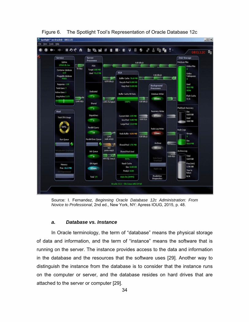
Figure 8. Data files, Redo Log files, and Control Files .................................. 37
Figure 9. Typical Oracle Data Guard Configuration ...................................... 40
Figure 10. A Picture of Oracle Enterprise Manager Cloud Control Console ......................................................................................... 44
Figure 11. Data Guard Management Page ..................................................... 45
Figure 12. The Design of the System ............................................................. 51
Figure 13. The Flow Chart of the System Implementation .............................. 54
Figure 14. The Configuration of the System for Testing ................................. 57
Figure 15. The Result of the Reading from Databases Test ........................... 60
Figure 16. Inserting 2000 Rows When Both Databases Are Up ..................... 62
Figure 17. Inserting 2000 Rows When the Standby Database Is Down ......... 62
Figure 18. Inserting 2000 More Rows When the Standby Database Is Down ............................................................................................. 63
Figure 19. Two Databases Are Synchronized ................................................ 63
Figure 20. The Output Before Running Step 6 ............................................... 65
Figure 21. Inserting 4000 Rows from Two Different Terminals ....................... 65
Figure 22. Two Databases Are Synchronized ................................................ 66
Figure 23. The Output Before Running Step 8 ............................................... 66
Figure 24. Inserting 4000 Rows from Two Different Terminals When the Standby Database Is Down ........................................................... 67
Figure 25. Two Databases Are Synchronized ................................................ 67
Figure 26. The Number of Entries in the Test Table Before Running the Four Switchovers in a Single Thread Test ..................................... 71
Figure 27. Switchover #1 (Single Thread Scenario) ....................................... 72

xii
Figure 28. Switchover #2 (Single Thread Scenario) ....................................... 72
Figure 29. Switchover #3 (Single Thread Scenario) ....................................... 73
Figure 30. Switchover #4 (Single Thread Scenario) ....................................... 73
Figure 31. The End of Four Switchovers in a Single Thread Test .................. 74
Figure 32. The End of Four Switchovers in a Single Thread Test (No Printout Statements) ...................................................................... 74
Figure 33. The Number of Entries in the Test Table Before Running the Four Switchovers in Multiple Threads Test .................................... 75
Figure 34. Switchover #1 (Multiple Threads Scenario) ................................... 75
Figure 35. Switchover #2 (Multiple Threads Scenario) ................................... 76
Figure 36. Switchover #3 (Multiple Threads Scenario) ................................... 76
Figure 37. Switchover #4 (Multiple Threads Scenario) ................................... 77
Figure 38. The End of Four Switchovers in Multiple Threads Test ................. 77
Figure 39. The End of Four Switchovers in Multiple Threads Test (No Printout Statements) ...................................................................... 78
Figure 40. The Number of Entries in the Test Table Before Running a Failover in Multiple Threads Test .................................................. 78
Figure 41. The End of a Failover in Multiple Threads Test ............................. 79
Figure 42. The End of a Failover in Multiple Threads Test (No Printout Statements) ................................................................................... 79
Figure 43. Enabling Archiving and Force Logging .......................................... 90
Figure 44. Adding 50MB Standby Redo Log Files .......................................... 91
Figure 45. Tnsnames.ora File ......................................................................... 91
Figure 46. Listener.ora File ............................................................................. 92
Figure 47. Creating Required Directories for the Standby Database .............. 93
Figure 48. RMAN Script that Duplicates the Primary to the Standby .............. 93
Figure 49. Showing the Primary Database Broker Parameters ...................... 94
Figure 50. Showing the Standby Database Broker Parameters ..................... 94
Figure 51. Creating the Broker Configurations-I ............................................. 95
Figure 52. Creating the Broker Configurations-II ............................................ 95
Figure 53. Creating the Broker Configurations-III ........................................... 96
Figure 54. Showing the Primary Database Properties-I .................................. 96
Figure 55. Showing the Primary Database Properties-II ................................. 97

xiii
Figure 56. Showing the Standby Database Properties-I ................................. 97
Figure 57. Showing the Standby Database Properties-II ................................ 98
Figure 58. The Configuration of Data Guard, with MaxPerformance .............. 98
Figure 59. The Configuration of Data Guard, with MaxAvailability .................. 99
Figure 60. Showing the Initial Transport Method ............................................ 99
Figure 61. Modifying the Transport Mode to Synchronous ........................... 100
Figure 62. Verifying the Transport Method ................................................... 100
Figure 63. Creating a Redo Gap Between Primary and Standby ................. 101
Figure 64. Restarting the Standby Database ................................................ 101
Figure 65. Verifying Primary and the Standby Databases Automatic Synchronization ........................................................................... 102
Figure 66. Showing the Protection Mode Configuration-I ............................. 102
Figure 67. Showing the Protection Mode Configuration-II ............................ 103
Figure 68. Switchover from the Primary Database to the Standby Database ..................................................................................... 103
Figure 69. Showing Parameters for Flashback Database ............................ 104
Figure 70. Enabling Flashback Database on Both Databases-I ................... 105
Figure 71. Enabling Flashback Database on Both Databases-II .................. 105
Figure 72. Enabling Flashback Database on Both Databases-III ................. 106
Figure 73. Shutting Down the Primary and Showing Configurations ............ 107
Figure 74. Successful Manual Failover ......................................................... 107
Figure 75. Verifying that the Standby Database Became the Primary .......... 108
Figure 76. Starting Up the Standby Database (Previously the Primary) ....... 108
Figure 77. The Broker Initiates Reinstatement of Database that Shut Down Unexpectedly ..................................................................... 109
Figure 78. Success after Reinstating the Database that Shut Down Unexpectedly ............................................................................... 109
Figure 79. Success in Configuration after Switchover to the Database that Shut Down Unexpectedly ..................................................... 110
Figure 80. Changing the Fast-Start Failover Threshold ................................ 111
Figure 81. Enabling Fast-Start Failover ........................................................ 111
Figure 82. Starting the Observer .................................................................. 112
Figure 83. Verifying the Observer Is Started................................................. 112
xiv
Figure 84. Shutting Down the Primary Database for Fast-Start Failover ...... 113
Figure 85. Examining the Actions in the Observer during the Fast-Start Failover ........................................................................................ 113
Figure 86. The Configuration after Fast-Start Failover ................................. 114
Figure 87. Restarting the Previous Primary Database .................................. 114
Figure 88. Examining the Actions in the Observer after Restarting the Previous Primary Database ......................................................... 115
Figure 89. Success after Fast-Start Failovers ............................................... 115

xv
LIST OF ACRONYMS AND ABBREVIATIONS
C2 command and control
DBA database administrator
DGMGRL Data Guard command line interface
HDFS Hadoop Distributed File System
RAID Redundant Array of Inexpensive Disks
URL Uniform Resource Identifier

xvi
THIS PAGE INTENTIONALLY LEFT BLANK

xvii
ACKNOWLEDGMENTS
I would like to thank to Man-Tak Shing for his support and guidance, Arijit
Das and Greg Belli for their help on databases, my father, Bahri Elmas, my
mother, Yildiz Elmas, and my brother, Emre Elmas, for their support during my
time in Monterey.

xviii
THIS PAGE INTENTIONALLY LEFT BLANK
1
I. INTRODUCTION
This chapter is an introduction to the thesis. The background in the
research area, the purpose of the thesis, its scope and limitations, thesis
question, and the organization of the thesis are presented in this chapter.
A. BACKGROUND
Navy platforms operate under all weather and sea conditions. Therefore, it
is imperative that the systems running on such platforms be robust. In the real
world, however, this is hard to achieve since there are many radars and sensors
connected to the majority of systems. Moreover, since many users operate a
single system simultaneously and in shifts, this burden exacerbates the potential
for error. Yet even under these circumstances, active Navy platforms’ systems
have to be resilient and reliable—up almost all the time. That means the systems
have to be fault-tolerant against users, errors from sensors/radars, system errors,
and physical or hardware errors.
As technology has developed during the past four decades, most of the
equipment used on Navy platforms has become more dependent on computers.
In today’s Navy platforms, most of the critical operations are run with the help of
automated systems. The designed automated systems have to be robust, fault
tolerant, and have high survivability. Otherwise, rather than being freed up to
focus on operations, personnel will be beleaguered with the problems that occur
in the automated system.
A modern approach to ensuring the robustness of these systems is to
have multiple systems (or servers) running at the same time that back up one
another. This thesis attempts to solve these problems or find an alternative
solution with a fault-tolerant, virtual server-based system framework. Our goal is
to overcome shortcomings with a cost and space-efficient, user-friendly
approach.

2
B. PURPOSE OF THIS THESIS
The main purpose of this thesis is to find an alternative way to ensure the
fault tolerance of data storage and retrieval in command and control systems (C2
systems) of Navy platforms, especially when the data is in transit. By doing this,
when a problem occurs in system data storage and distribution units, the C2
system will find an alternative way to stabilize itself and recover from an
unintended state to a normal one. The concept of fault tolerance has to be
implemented in the C2 system according to a plan to ensure the system will
behave as expected in wartime under any circumstances. Thus, an
implementation plan must include these essential considerations:
The C2 system itself must have no single point of failure. This also means that there must always be a way for the system to compensate for failures.
Although it is impossible to have a zero-failure environment, the C2 system must maintain stability and have a flawless runtime by being able to rapidly switch to alternative data resources at the time of failure.
The required time to switch between main data resource and alternative should be minimal.
Switching between data resources at the time of failure must not affect the rest of the system, especially ongoing processes of high importance.
The C2 system needs to recover itself instantly. Moreover, it also needs to check the status of the main data resource frequently to switch back to that resource as soon as the problem is resolved.
This thesis tries to answer the following question:
Is there a better way to ensure the fault tolerance in command and control systems of Navy platform databases in terms of economics and performance?
C. SCOPE AND LIMITATIONS OF THIS THESIS
The scope of this thesis is to find an alternative way to have a fault
tolerance in databases in C2 systems of Navy platforms using Oracle Database
12c and its features and to test it respectively according to fault tolerance

3
concepts. This thesis mainly focuses on Oracle Database 12c and Oracle Data
Guard, which run on the Fedora operating system.
In this thesis, we used Oracle VirtualBox as a hypervisor for the virtual
environment that we worked on. We also used Fedora operating system to install
the Oracle Database 12c. We created two databases in the system. Those two
databases use the localhost as host and different service names to communicate
via Data Guard. They also have four standby redo log files, which have the size
of 50MB each. The listener and Data Guard command-line interfaces (DGMGRL)
are used for the communication of the system. The observer is installed on the
same operating system.
In addition to those system characteristics previously mentioned, we also
connected to the databases as a normal user (in other words, as a client) using
Java codes on the same operating system. In this framework, instead of making
the client failover scenarios transparent to clients using one single connection
URL (Uniform Resource Identifier), we explicitly used two URL strings in order to
connect to the databases so that we can measure the time to wait for changing
the connection URL in between failover or switchover testing scenarios by
extensive tests that are independently calculated in the system.
D. ORGANIZATION OF THIS THESIS
Chapter I provides a general overview on the thesis. In Chapter II, we
cover the fault tolerance concept by introducing definitions of fault, system
failure, and error as well as many other definitions related to the fault tolerance
concept. After presenting those definitions, we review some technologies that
ensure fault tolerance. After that, we introduce Error Detection and Error
Correction subjects as the stages of fault tolerance. We conclude this chapter
with five major objectives of fault tolerance: Reliability, Availability, Safety,
Maintainability, and Dependability.

4
In Chapter III, we specifically focus on the fault tolerance in Oracle
Databases. We explain the Data Guard feature in this chapter. We also present
how Data Guard synchronizes databases in this part of the thesis.
In Chapter IV, we introduce the design and implementation of the system
for fault tolerance in databases. After introducing the design and implementation,
we present various testing cases and findings.
In Chapter V, we conclude the study and recommend some ideas for
future studies.

5
II. A REVIEW OF FAULT TOLERANCE
In this chapter, definitions of fault, system failure, and error as well as
many other definitions related to the fault tolerance concept are discussed. After
presenting those definitions, we review some technologies that ensure fault
tolerance. Hot Swapping, RAID (Redundant Array of Inexpensive Disks), and
Apache Hadoop technologies are presented under the technologies section.
After that, Error Detection and Error Correction subjects are introduced as stages
of fault tolerance. This chapter concludes with five major objectives of fault
tolerance: Reliability, Availability, Safety, Maintainability, and Dependability.
A. AN OVERVIEW OF FAULT CONCEPT
In this part of the thesis, introducing the breakages of dependable
computing in the first place is a good starting point. There are a few impairments
to dependable computing such as faults, errors, and failures in the system [1].
A user can only perceive the part of the system that is being interacted
with as the system behavior. A normal system behavior would be getting the
expected service back from the system. For example, when clicking on the
“Save” button on a Microsoft Word document, if the system is saving the
document that the user wanted to save, then that is the normal system behavior.
Another example, when the user wants to make a simple calculation using a
calculator, the normal system behavior should be getting the correct outcome
after the user presses the “=“ button.
On the other hand, a system can respond with an unusual or unintended
behavior. This can be explained further using the examples just given, but ending
with different results. When clicking on the “Save” button on a Microsoft Word
document, the system does not save the document that the user wanted saved,
or the calculator produces the wrong outcome after the user presses the “=“
button.

6
The service that is delivered by a system can also be interchangeably
called the system behavior. A system failure happens when the delivered service
is not the same as the specified service, as opposed to the normal system
behavior. A system failure is a specific type of unusual behavior, because it is not
intended. An error is a part of the system itself, and an error may also be the
underlying cause of the failure. An error, which is introduced into the system by a
programmer, may lead to a fault, and that fault can cause a system failure [1], [2].
Here are some related definitions taken from the IEEE Standard Glossary
of Software Engineering Terminology:
Error: The difference between a computed, observed, or measured value or condition and the true, specified, or theoretically correct value or condition. For example, a difference of 30 meters between a computed result and the correct result.
Fault: An incorrect step, process, or data definition. For example, an incorrect instruction in a computer program.
Failure: An incorrect result. For example, a computed result of 12 when the correct result is 10.[2]
To put the definitions in an order for a better understanding, here is the
typical system behavior when there is a system failure: an error creates a hidden
fault, which becomes effective after its activation, and the system failure happens
when the fault, which was hidden beforehand, affects the normal system
behavior or the service. In other words, a fault is the result or the appearance of
an error in the system, and a failure is the result or the appearance of a fault in
the system [1], [2].
A fault, in a general sense, is a kind of physical defect that happens in the
software or hardware parts of the system [3]. Since a system is too big and
complex, it is impossible to test every single sub-system and part—especially
when no failure is observed. For this reason, it is quite hard to foresee a fault.
When there is a fault in the system, it is not certain that there is a failure in the
system. A failure only happens if a hidden error is activated and causes a fault;
then a hidden fault is activated and causes a failure to happen. On the other
7
hand, a failure in the system assures that there is a fault. Therefore, an error is
present in the system.
Here are some more examples on the notion of error and fault concept:
A programmer’s mistake, which is in the code, is a kind of error. The consequence of that error is a hidden fault that is in the program. That particular fault stays hidden or silent until it is activated. At that point, that fault creates an erroneous data, thus, a failure happens [1].
A hardware defect in hard disk is a kind of fault. That particular fault stays hidden or silent until it is activated. At that point, that fault creates an erroneous data, thus, a failure happens.
Like the previous example, there are some other similar types of fault such as an electromagnetic unsteadiness because of change of energy and an inappropriate man-machine interaction [1].
A mistake, typographical error, or misleading instructions in a maintenance or operating manual is a kind of error. Actually, this example is a very good one, since it shows us that failures are not always about software or at hardware level. Failures can be related to operators, weather conditions, and even documentation, in addition to software and hardware infrastructure. It is simply because we cannot separate any system from the outer environment, or from people who are interacting with them. In this maintenance or operating manual example, the error will stay as hidden in the maintenance or operating manual until the directive, which has an error in it, is applied to the system [1], [2].
There are various reasons behind faults. Examples include:
Physical faults: short-circuits in the hardware level, temperature, vibration, heat, humidity, etc[1]..
Human-made faults: generally human-made faults happen from some other reason, such as the following:
Design faults: this type of fault is generally made during system design or system modifications, or during the creation of maintenance or operating manuals.
Interaction faults: deliberate or non-deliberate faults of operators. This type of error may occur because of the lack of personnel training [1].
8
B. AN OVERVIEW OF THE FAULT TOLERANCE CONCEPT
In this section, the concept of fault tolerance is presented. It is a highly
important subject in the modern computing world, because there are numerous
activities, including those that shape countries’ economies and—even more
important—those that protect human lives, that should be running with minimal,
or if possible, no faults.
1. Definitions
A system is fault tolerant if it can tolerate or minimize the effects of the
existing faults in the system by the help of redundancy [4]. Actually, it is easier
said than done. The system cannot be made fault tolerant against every single
fault as a whole. The utmost aim of fault tolerance is avoiding the total system
failure when some sub-parts or sub-systems fail [4].
Another definition of fault tolerance can be given as a system is treated as
fault tolerant provided that the system behavior or, in other words, expected
service is consistent with the normal system behavior, even when there are some
failures in the system [4].
Having a fault tolerance in the system may have some minor adverse
effects such as decline in the overall performance or limitations of total disk
capacity. However, these effects are not so important in comparison to the failure
of the total system.
Redundancy is the key behind the fault tolerance concept [4]. From
another perspective, fault tolerance cannot be offered without any means of
redundancy [4]. Redundancy is defined as a kind of abundance of resources,
where those resources would be not used or not needed as the system is
running without faults [4]. More about the redundancy concept is presented in the
next section.
There are a few more definitions related to the fault tolerance discussion
worth noting:

9
Fault avoidance is preventing the possibility of fault occurrence.
Error removal is minimizing the existence of hidden errors in the system by using verification.
Error forecasting is estimating the presence, occurrence and consequences of errors in the system [1].
Fault tolerance and fault avoidance are mainly part of dependability
acquisition, which means giving the best effort to deliver the specified service. On
the other hand, error removal and error forecasting are mainly part of
dependability validation, which means getting enough confidence off the system
on delivering the specified service [1].
2. Redundancy Concept
Under normal operation, a redundant part of a system is abundant and
does not participate with the parts that are actively involved in the system run [4],
[5].
According to Koren, “Redundancy is the property of having more of a
resource than is minimally necessary to do the job at hand. As failures happen,
redundancy is exploited to mask or otherwise work around these failures, thus
maintaining the desired level of functionality.” [6]
To qualify as a fault tolerant system, the system has to have redundancy.
Redundant parts are to be used in place of a failed part when there is a failure in
the system. Redundancy may bring some side effects into the system. Decrease
in performance, the expansion in the total system size and weight, and a hike in
the system cost can be counted in those adverse effects [5].
There are four types of redundancy in a general aspect. These
redundancies are hardware redundancy, software redundancy, time redundancy,
and information redundancy [5], [6].
Hardware redundancy can be established by having extra or, in other
words, abundant hardware in the system for mainly two purposes. One is to
detect the effects of a failed component in the system, as in run-time testing

10
uses. The other is overriding the effects of a failed part. For example, we can
have two or more power supplies, each performing the same function by giving
adequate redundancy to ensure our system will run as intended, instead of
having a single power supply in our system. We can detect the error in a running
power supply if we have two power supplies. If we have three power supplies, we
can override the effects of a failed power supply, and so on. We can give the
power supply instance just presented as a static hardware redundancy example.
The main goal of static hardware redundancy is to mask the failure immediately
by allowing the system to run as if there is no failure at all. There is another type
of hardware redundancy, which is called dynamic redundancy, which activates
the spare components in the system as a failure occurs. In this dynamic
hardware redundancy, spare components in the system are not used during
normal operation, and they will be waiting passively until there is a failure and the
need for them occurs. Both static and dynamic redundancy approaches for
fulfilling the users and systems needs are called hybrid hardware redundancy [6].
3. Some Technologies that Ensure Fault Tolerance
Some technologies have been developed over the years to ensure the
fault tolerance in a given system. In this section, Hot Swapping, RAID, and
Apache Hadoop system is presented here.
a. Hot Swapping
Hot swapping is a general term to describe the functions that change
some parts without shutting down the whole system. Hot swapping function also
keeps the system running with no interruption or only a minor interruption at the
worst case. There are two main types of hot swapping, known as hardware hot
swapping and software hot swapping [7], [8].
The idea behind hardware hot swapping is to have abundant disks or
hardware components in order to keep the system running normally, even if there
is a failure. Hot swapping is strictly a hardware function and requires no
commands from the terminal or manual operation. If this were the case of

11
applying a manual procedure or putting the system in sleep mode or in any state
other than the normal one, then this would not be a fault tolerant system at all.
According to [8], software hot swapping is the technology term that
explains the “replacement of a software program or a part of a program while the
whole software system remains in operation” [8]. Hot swapping indicates the
ability to replace the parts that are not functioning without the user’s notice [7].
According to Feng [8], “Software upgrading, needed for bug-fixes,
updates, or functionality upgrades, is generally not easy. It is particularly difficult
in computer communication networks where software can be widely distributed
across heterogeneous domains. The problem is complicated even further by the
requirement in some applications for almost 100% availability. As a result, in
many cases it is extremely important not to have to take a system off line for
software upgrading and/or recompilation.”
There are some issues in software hot swapping, such as the Referential
Transparency Problem, the State Transfer Problem, and the Mutual Referential
Problem [8], [9].
b. RAID
RAID is the abbreviation for “Redundant Array of Inexpensive Disks.” It is
a technology for storing data that associates multiple physical hard drives into a
logically, or seemingly, single unit. This technology is designed primarily to
provide fault tolerance, large storage capacity, and faster disk access. The main
focus areas in this technology are performance and reliability [10].
There were five standard RAID levels originally; however, many more
have evolved as time passed [10]. The standard RAID levels are named as RAID
and a number starting from 0. For example, standard RAID levels are named as
RAID 0, RAID 1, and so on. In addition to standard RAID levels, it is possible to
create hybrid levels. The most common examples of hybrid RAID levels are just
one level deep. In other words, generally two standard levels are combined to

12
create hybrid RAID levels. Combined RAID levels are named as RAID and the
combination of numbers that forms the specific RAID combination. For example,
combined RAID levels are named as RAID 0+1, or RAID 01, if that combined
RAID level is the combination of RAID 0 and RAID 1 [10].
Standard RAID levels 0 through 6 are illustrated in Figure 1.
Figure 1. RAID Levels 0 through 6
Source: P. Chen P et al., “RAID: High-performance, reliable secondary storage,” ACM Computing Surveys (CSUR) vol. 26, no. 2, p. 153, 1994.
13
RAID 0 is disk striping. In RAID 0, there are multiple physical hard disks
that form a big single disk. For example, if we have four 1 GB hard disks in our
system and we use RAID 0, then we have 4 GB of total capacity. In other words,
we sum the total capacities of each disk in order to find the capacity of our RAID
0 volume. RAID 0 does not offer any type of redundancy for disk failures. If a disk
failure happens, then all the data in that disk is practically lost.
Disk mirroring technology is known as RAID 1. In RAID 1, in short,
multiple physical disks look like one disk. This technology will duplicate the same
data onto a paired disk; yet, they will look like one disk. For a simple example,
assuming that we have four 1 GB hard disks in our system and we use RAID 1,
then we could have two pairs of disks for creating real-time disk copy; therefore,
the whole disk capacity may look like 2 GB instead of 1 GB. We could visualize
the same example as we do have two pairs, each having two 1 GB disks in it,
and each pair looks like one disk. RAID 1 provides fault tolerance by redundancy.
If one disk fails, we can still work because the other disk in the pair (by saying
‘pair’ here, we are trying to refer to the example that we gave earlier) has the
exact copy of the failed disk. We can also change the damaged or broken hard
disk while the system is running. RAID 1 enables the hot swapping technology,
which is presented in the previous subsection. The biggest disadvantage of RAID
1 is that we lose half of our performance and half of our total disk capacity. RAID
1 technology does not hold a backup for users. It only works on hard disk
failures, where it offers fault tolerance by redundancy. For example, when a user
deletes a file from the hard disk, the exact copy is deleted from the disk next to it
(that is, from the other disk holding the exact copy of the previous disk).
RAID 5 is known as “block-level striping with distributed parity” [11]. This
RAID level has a place in between RAID 0 and RAID 1. We can reconstruct the
data after failing, with the help of parity bits and error correction codes. If a disk
fails, we can replace it before any other disks fail and continue our work, and the
user can feel the degraded performance. According to [11], “Upon failure of a

14
single drive, subsequent reads can be calculated from the distributed parity such
that no data is lost. RAID 5 requires at least three disks.”
c. Apache Hadoop
Apache Hadoop is a “framework that allows for the distributed processing
of large data sets across clusters of computers using simple programming
models” [12].
The core of Apache Hadoop has two main parts as the storage part and
the processing part. The storage part is called the Hadoop Distributed File
System. The processing part is called the MapReduce.
Hadoop Distributed File System (HDFS) stores large files that are
generally in the range of gigabytes to terabytes across multiple machines [13].
HDFS is managed by daemon processes, which are as follows:
NameNode: Master process
DataNode: Slave process
Checkpoint NameNode (or Secondary NameNode): Checkpoint process
BackupNode: Backup NameNode [13]
HDFS architecture is presented in Figure 2.
15
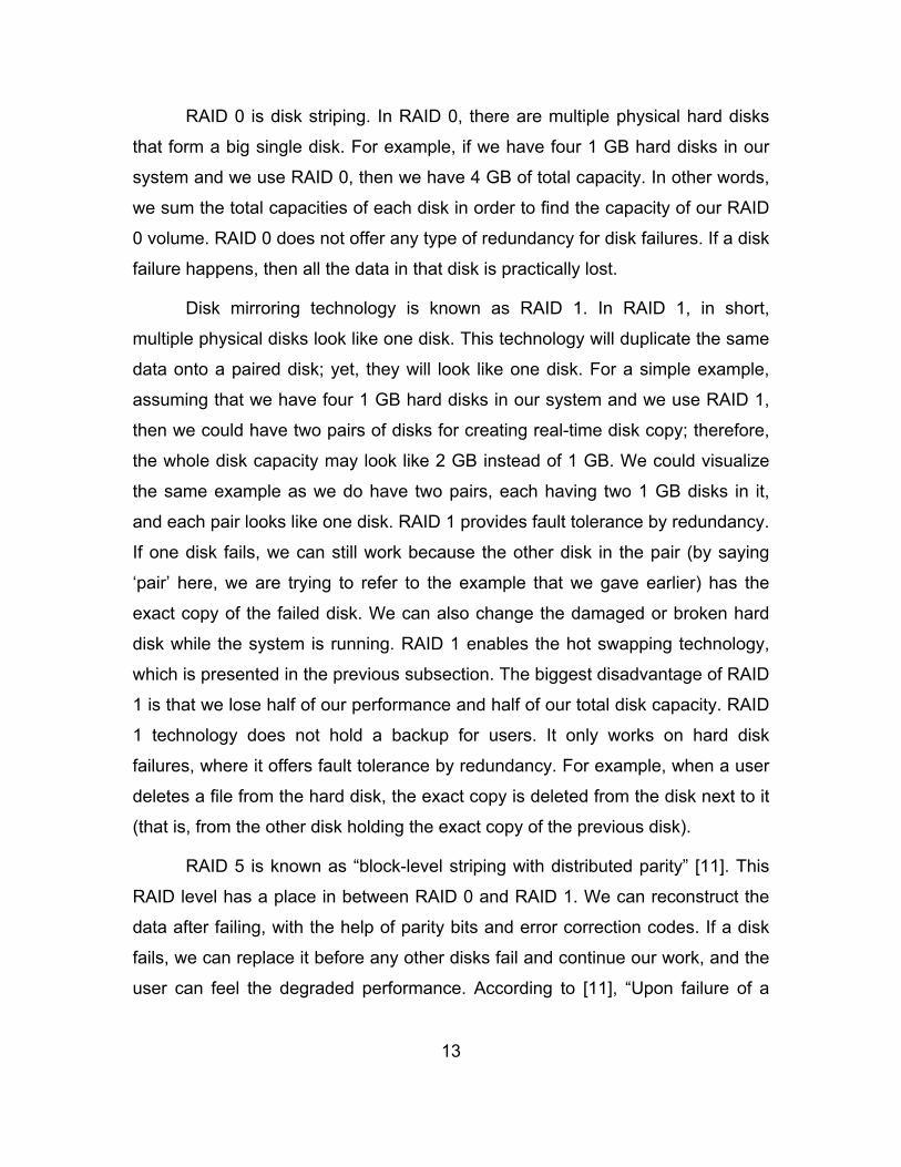
Figure 2. HDFS Architecture
Source: D. Borthakur. (2011, Apr. 04). Apache Hadoop filesystem and its usage in Facebook. [Online]. Available: http://cloud.berkeley.edu/data/hdfs.pdf
NameNode is the master process daemon server in HDFS that
coordinates all the operations related to storage in Hadoop, including the reads
and writes in HDFS. NameNode manages the filesystem namespace.
NameNode holds the metadata about all the file blocks, and in which all nodes of
data blocks are present in the cluster [13].
DataNode holds the actual data in HDFS and is also responsible for
creating, deleting, and replicating data blocks, as assigned by NameNode [13].
Checkpoint NameNode, earlier known as Secondary NameNode, is a
node that has frequent data check points of FsImage and EditLog files merged
and available for NameNode in case of any NameNode failure. Checkpoint
NameNode collects and stores the latest checkpoint [13].
16
BackupNode is similar to Checkpoint NameNode, but it keeps the updated
copy of FsImage in RAM memory and is always synchronized with NameNode
[13].
MapReduce is a
programming model and an associated implementation for processing and generating large data sets. Users specify a map function that processes a key/value pair to generate a set of intermediate key/value pairs, and a reduce function that merges all intermediate values associated with the same intermediate key [14].
MapReduce provides “automatic parallelization and distribution,” “fault
tolerance,” “input and output scheduling,” and “status monitoring” [14].
MapReduce, which is fault tolerant software, is designed to avoid server
problems. According to Dean, “When a machine fails, the master knows what
task that machine was assigned and will direct the other machines to take up the
map task. You can end up losing 100 map tasks, but can have 100 machines
pick up those tasks” [15].
According to Shankland,
The MapReduce reliability was severely tested once during a maintenance operation on one cluster with 1,800 servers. Workers unplugged groups of 80 machines at a time, during which the other 1,720 machines would pick up the slack. “It ran a little slowly, but it all completed,” Dean said. … In a 2004 presentation, Dean said, “One system withstood a failure of 1,600 servers in a 1,800-unit cluster” [15].
C. OBJECTIVES OF FAULT TOLERANCE
Fault tolerance is an attribute built in a system that ultimately seeks to
meet design requirements. The most significant requirements are dependability,
availability, reliability, safety, and maintainability [3], [5].
17
1. Dependability
The definition of dependability according to Avizienis et al. is “the ability to
deliver service that can justifiably be trusted. This definition stresses the need for
justification of trust. The alternate definition that provides the criterion for deciding
if the service is dependable is the dependability of a system is the ability to avoid
service failures that are more frequent and more severe than is acceptable” [16].
Avizienis et al. also state, “It is usual to say that the dependability of a
system should suffice for the dependence being placed on that system. The
dependence of system A on system B, thus, represents the extent to which
system A’s dependability is (or would be) affected by that of System B. The
concept of dependence leads to that of trust, which can very conveniently be
defined as accepted dependence” [16].
Dependability is a concept that integrates and covers some other
concepts in fault tolerance, which are summarized by [16] as:
Availability: the state of being available for desired service
Reliability: ensuring that the ongoing service is correct
Safety: ensuring that no catastrophic consequences will result to users and the system
Maintainability: the flexibility of going into small or big changes, yet still being able to function
2. Availability
The availability of a system can be expressed with a function, expressed
as the probability that “the system is operating correctly and available” to its
users at time t [3]. Availability is an important metric for systems. Most of the big
technology enterprises introduce their products with an availability metric, as well
as the specifications of that product. Figure 3 gives the availability chart for
systems in general.

18
Figure 3. Availability Chart for Systems
Source: M. Malek. (2004, May). Dependable systems introduction. [Online]. Available: http://www2.informatik.hu-berlin.de/rok/zs/WS0405/data/slides/zs01_04Intro.pdf
System availability can be given in a chart after calculating the ratio of the
time where the system is available to the total. Figure 4 shows some common
classes with the associated availability percentages and annual downtime of the
system [5]. Systems are named after the total number of 9’s they have in their
availability measurement. For example, if a system has the value of 99.9% for
system availability, then the system can be named the three nines system.
Alternatively, the system can be expressed as an availability class. For instance,
if a system has a value of 99.995% for system availability, then the system can
be categorized as Class 4, since 99.995% is between 99.99% and 99.999% [5].

19
Figure 4. Availability Classes
Source: E. Kati, “Fault-tolerant approach for deploying server agent-based active network management (SAAM) server in Windows NT environment to provide uninterrupted services to routers in case of server failure(s),” M.S. thesis, Dept. Computer Science, Naval Postgraduate School, Monterey, CA, 2000.
3. Reliability
The reliability of a system is a “function of time, R(t), defined as the
conditional probability that the system performs correctly throughout the interval
of time, [t0,t], given that the system was performing correctly at a time t” [3]. In
other words, it is a measure of the “continuous service accomplishment from a
reference initial instant” [3].
According to Sorin [17], “Unless a system failure is catastrophic (e.g.,
avionics), reliability is a less useful metric than availability.”
The reliability of a system can be expressed with the ‘Bathtub Curve,’
which is given in Figure 5. Generally, there are three phases in a system’s life in
terms of failure rate, which are decreasing failure rate, constant failure rate, and
increasing failure rate. It is quite important to determine the time projections,
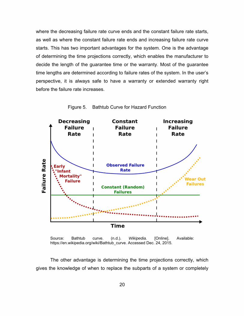
20
where the decreasing failure rate curve ends and the constant failure rate starts,
as well as where the constant failure rate ends and increasing failure rate curve
starts. This has two important advantages for the system. One is the advantage
of determining the time projections correctly, which enables the manufacturer to
decide the length of the guarantee time or the warranty. Most of the guarantee
time lengths are determined according to failure rates of the system. In the user’s
perspective, it is always safe to have a warranty or extended warranty right
before the failure rate increases.
Figure 5. Bathtub Curve for Hazard Function
Source: Bathtub curve. (n.d.). Wikipedia. [Online]. Available: https://en.wikipedia.org/wiki/Bathtub_curve. Accessed Dec. 24, 2015.
The other advantage is determining the time projections correctly, which
gives the knowledge of when to replace the subparts of a system or completely
21
remove and replace with the upgraded version of the system before the failure
happens, especially in the military domain, where almost all systems are critical.
Assuming that the system life time is exponentially distributed, the
reliability of that system is e-λt [5]. In the formula, λ is the failure rate of the system
and t is the time interval. The expected failure numbers per the unit of time is
called the failure rate of that system [5].
According to Pradhan, “The exponential relationship between the reliability
and the time is known as the exponential failure law. The exponential failure law
is very important for the analysis of electronic components, and is by far the most
commonly used relationship between reliability and time” [3], [5].
4. Safety
According to Pradhan, “Safety, S(t), is the probability that a system will
either perform its functions correctly or will discontinue its functions in a manner
that does not disrupt the other systems or compromise the safety of any people
associated with the system” [3]. Safety is a representation of the fail-safe
capability in a system. If the system does not function as expected, we expect it
to fail in the safest way [3], [5].
The concept of reliability differs from the concept of safety. Reliability can
be expressed as a probability of any system’s correct overall function
performance. On the other hand, safety tells that the system will either function
correctly or will run without interrupting the whole process. The concept of safety
is expressed with a probability. It is astute to say that if a system is reliable, it is
also safe. On the other hand, we cannot conclude the other way around [5].
5. Maintainability
According to Pradhan [3], “The maintainability is a measure of the ease
with which a system can be repaired once it has failed.” It is the “probability that a
failed system will be restored to an operational state” within a certain and
acceptable period of time [3], [5].

22
According to Kati, “Maintainability encapsulates not only the failures of the
system, but also the modifications that are necessary for the required level of
system performance” [5]. System functions must be maintained and upgraded
regularly to ensure that the system meets user expectations and needs.
Performing these maintenance activities can be made easier if the system is
highly modular [5]. Kati further states that “If the consequences of a modification
can be localized to well-defined small modules, then the maintenance effort can
be minimized. Fault tolerance can support maintainability in the problem
detection and problem location process. The maintenance of the system can be
done after the detection and the localization of the failure. Fault tolerance can
also support maintainability in the modification process by allowing maintenance
actions without interrupting the service delivered by the system” [5].
D. FAULT TOLERANCE STAGES
The systems that have fault tolerance try to continue providing normal
service despite having failures in some subcomponents. The most important
parts of fault tolerance are error detection, damage confinement, error recovery,
and fault treatment and continued system service [18].
Error detection is the first stage, where a fault and, therefore, an error is
detected in a subcomponent. The detection of an existing error implies that a
failure may occur on that subcomponent, as discussed in the section “An
Overview of the Fault Concept,” earlier. After detecting the error, the system has
to identify and bound the limits of the damage that was the consequence of the
failure. This stage is known as damage confinement. In these first two stages,
the error is detected, and efforts for limiting the estimated boundaries of the
damage caused by the failure are endeavored. These first two stages can be
grouped as detection stages.
Errors and faults have to be detected before starting the further work for
fault tolerance. When the system finishes these first two stages, errors and faults
need to be corrected for enabling the normal service to be delivered to users.

23
This is the responsibility of the error recovery stage. Error recovery stage will
take the system to an error-free state, by removing errors that occurred
beforehand.
After the error recovery stage, the fault treatment and continued system
service stage comes into action for identifying the faulty component or
components.
1. Error Detection
In the extent of fault tolerance, error detection is the very first step. In the
best case, we expect the error detection mechanism to detect every single error
in the system, which is only ideally true. In reality, however, it is not quite
possible.
There are certain features that an ideally feasible error detection
mechanism should fulfill. First, the error detection should not be affected by the
system design. Therefore, the best approach is seeing the system as a black
box, like a function structure in any programming language [4], [5].
Second, the error detection mechanism should be sound and complete.
This can be achieved by detecting all possible errors, and the declared errors
should indeed be in the system [4], [5]. The detection mechanism should avoid
giving false positives [4], [5].
Third, the check should be independent from the system in terms of being
vulnerable to failures. The detection mechanism should not fail at system
failures; otherwise, the whole error detection phase would be unproductive and
meaningless, which amounts to having a different error detection failure
mechanism than the actual system [4].
These three criteria can rarely be met in systems in real life due to many
difficulties. It is very hard to identify every single error in the system. The
complete test of error detection is very costly and time-consuming [4].

24
Because of the aforementioned reasons, in most of systems, checks for
acceptability are made instead of checks for ideality. In other words, checks for
acceptability are the approximation of checks for ideality. The main aim in this
perspective is to lower the cost of error detection checks, as well as trying to
keep the error detection performance maximized. In the checks for acceptability
approach, most errors in the system are expected to be caught in a predefined
confidence interval. Here are some general types of error detection checks that
are used frequently:
(1) Replication Checks
Replication checks are one of the most broadly used and effective checks.
These types of checks have advantages in terms of ease of use and
completeness in checks [4]. They can also be applied to a system with a little
knowledge of internal system dynamics. As it may be understood from the name,
these checks depend on replicating some components of the system. Therefore,
replication checks are highly expensive error detection methods [4]. Replication,
which is using identical copies of system parts, works provided that the interior
design of those parts is working as expected. On the other hand, if the interior
design of those parts is not working normally, replication checks will not succeed
either [4].
Replication has purposes other than solely for error detection, especially
in distributed systems [19]. Generally, data or processes, which are replicated in
distributed systems, enable the handling failures in the system easily [4].
(2) Timing Checks
If timing constraints are included in the interior design of system
components, timing checks can be used for checking whether timing constraints
are satisfied or not. Timing checks mainly play a big role both in hardware and
software systems for detecting problems. After setting the timer, the system will
check whether the timer has timed out. Having a timeout in the system indicates
25
that there is at least one component malfunctioning. In other words, a timing error
is an indirect indication of the existence of an error in the system [4].
(3) Structural and Coding Checks
Two types of checks are used in general, semantic checks and structural
checks. Semantic checks are used for verifying the value is consistent with the
rest of the system. Structural checks, on the other hand, are used for checking
data against data, which is the part of the normal behavior of the system, in the
internal design of system structure [4].
Structural checks are mainly used in hardware components of systems by
means of coding. Extra bits are added to actual data bits for error checking
purposes. When an inconsistency is found in coding bits with the help of extra
bits, the error is detected. These kinds of error detection mechanisms are mainly
used in hardware components of systems. Data structures that use redundancy
for enabling structural checks are known as robust data structures [20]. In robust
data structures, the system, which uses redundancy and structural checks, can
locate the error and also correct the corrupted part by using extra bits [4]. This
approach is used in RAID technology.
(4) Reasonableness Checks
Reasonableness checks decide whether the system status is reasonable.
For example, the range check, which is made to check whether the value is in a
specified range, is a type of reasonableness check. The range check only shows
whether the value is within the range. It does not say anything about the
correctness of the given value [4].
Inserting assertion statements in the code is another kind of
reasonableness check. By definition, an assertion is a logical expression on the
value of different variables in the system, which will evaluate to true if the state of
the system is consistent; otherwise, it will evaluate to false. It is a practical way to
detect errors, especially in software [4].

26
(5) Diagnostic Checks
The purpose of diagnostic checks is to determine whether the component
of a system is working correctly. In these types of checks, the system performs
diagnostic tests on a specific component. Systems mostly use previous known
correct values to check current values for comparison. Therefore, a mismatch in
comparisons equates to an error. Diagnostic checks, which are also known as
self-checks, mostly appear on startup times of systems [4].
2. Damage Confinement
When an error in the system is detected, it also points out one or more
faults that are present in the system. While it is good to detect a fault or faults in
the system, we need to deal with the problem of time delay as well. The time
delay in this context can be addressed as the time difference between the failure
and the time that we detected the error. One of the many reasons for the time
delay issue can be that we do not monitor the system all the time. Having some
problems in our log files can be the other reason. One way or another, the time
delay issue can lead to other problems in the other parts of system [4].
In this damage confinement phase, the boundaries of corruption have to
be determined before going ahead and correcting actual failures.
3. Error Recovery
After detecting the error in the system and determining the boundaries of
corruption, it is appropriate to start removing the error from the system. The main
goal of this phase is to clean the system of errors. It is very important to apply
error recovery on the system, so the system can lead to a consistent state. Two
techniques for error recovery are backward and forward recovery [4].
(1) Backward Recovery
When we exercise backward recovery, the system is restored to an earlier
state, where there is no error. In order to apply this error recovery technique, the

27
states of the system have to be saved periodically [4]. It is like taking backups,
such as full, incremental, or differential backups, of the system. We can call
those backup media checkpoints of the system. After isolating errors in the
system, we can roll back to a previous backup, ideally the most current one that
is known to be good. It is worth noting that the system has to be backed up
frequently to allow for successful backward recovery in the long term.
The biggest advantage of this approach is that we do not need to analyze
the possible causes of errors in order to apply the error recovery on the system.
Thus, error recovery will not take too much time. We will only roll our system
back to an earlier backup. It is also possible that we can investigate the reason
for the errors on a different test machine, while our actual system is running
normally. In large enterprises, this error-analyzing job can be given to special
departments.
(2) Forward Recovery
Unlike backward recovery, there is obviously no backup available in the
forward recovery technique. Therefore, this approach attempts to neutralize
errors in the system and make it run normally. We achieve this by correcting
existing errors [4].
It is quite obvious that the cause of an error has to be diagnosed and
learned before moving ahead and starting forward recovery. Consequently, a
very detailed error diagnosis has to be performed for forward recovery.
A special team of people has to work on error diagnosis for forward
recovery.
4. Fault Treatment and Continued System Service
The main focus in the first three phases is detecting errors, determining
the boundaries of corruption, and then removing the error from the system. After
the first three phases, the system should be free from errors. If the error is
temporary, or if it originated from a momentary variation in current, voltage, or

28
frequency, error detection, damage confinement, and error recovery will be
enough for the system to go back to an error-free state. Moreover, we can be
sure that when we reboot the system, it will run normally if temporary or transient
error is the case [4].
On the other hand, there may be some cases where the existing error is
the result of some permanent condition. If that is the case, even if we remove the
error from the system, after the restart or some amount of time; the same error
will reoccur. Therefore, we need to identify the faulty component and take that
component out of use in order to avoid the same error recurring repeatedly. The
main goal of this phase is to bypass the faulty component of the system without
affecting the normal runtime of the environment [4].
This fault tolerance stage has two main subparts, fault location and
system repair.
(1) Fault Location
In the fault location subpart, the faulty component has to be identified.
Unless the faulty component is found, full recovery cannot be made [4].
(2) System Repair
In the system repair subpart, the system will be repaired by either
replacing the faulty component with a new one or taking the faulty component out
of the system. In order to have a fault tolerant system, the system has to be
online during the process of system repair. If we must power off the system
during the system repair, we cannot call that system fault tolerant. Thus, the
system repair has to be done in an automated manner. The redundancy concept
plays a big role in this subpart [4].
One approach is having a working, errorless spare component in the
system so that the system will have a spare component that has the exact same
settings and properties as the affected component when a faulty component has
to be replaced [4].

29
Another approach is virtualizing the whole system. This approach is
cheaper than having a spare component in the system all the time. For some
projects, despite the cost, it is preferable to have an abundance of software
components for providing better system up time and more speed in terms of
overall system performance.
After we apply the system repair technique, the system will run normally.
The drawback of system repair may be a certain level of performance
degradation. On the bright side, though, the system will be available to all users
in that time [4].

30
THIS PAGE INTENTIONALLY LEFT BLANK

31
III. FAULT TOLERANCE IN ORACLE DATABASES
In this chapter, we discuss a specific technology, the Oracle Data Guard,
for database fault tolerance. Before discussing the specific features and uses of
Oracle Data Guard, we first provide an explanation of the product’s intended
purpose and value.
A. WHY ORACLE DATA GUARD
According to the official definition from the Oracle white paper, “Oracle
Data Guard is the management, monitoring, and automation software
infrastructure that creates, maintains, and monitors one or more standby
databases to protect enterprise data from failures, disasters, errors, and
corruptions” [21].
The same Oracle white paper also states:
Data Guard maintains these standby databases as synchronized copies of the production database. These standby databases can be located at remote disaster recovery sites thousands of miles away from the production data center, or they may be located in the same city, same campus, or even in the same building. If the production database becomes unavailable because of a planned or an unplanned outage, Data Guard can switch any standby database to [take on] the production role, thus minimizing the downtime associated with the outage, and preventing any data loss [22].
In addition to Oracle Data Guard, Oracle has another option, namely
Oracle Active Data Guard, which is a superset of Oracle Data Guard. Oracle
Active Data Guard is an option for the Oracle Database Enterprise Edition. It
provides advanced capabilities, such as Data Guard functionality, including Real-
Time Query, Automatic Block Repair, Far Sync, RMAN Block Change Tracking,
Active Data Guard Rolling Upgrade, Global Database Services, and Application
Continuity [23].

32
The ultimate goal of using Oracle Data Guard capability is to ensure the
High Availability, Quality of Service, Data Protection, and Disaster Recovery [24].
It can be clearly deduced that Oracle Data Guard is a means of ensuring Fault
Tolerance in the databases. To understand how particular characteristics of
Oracle Data Guard meet the Fault Tolerance Objectives, it is important to recall
the significant requirements described in the previous chapter: dependability,
availability, reliability, safety, and maintainability. Reliability is ensured in Oracle
Data Guard by real-time data protection. According to [19], “Oracle Data Guard
enables zero data loss disaster recovery (DR) across any distance without
impacting database performance. It repairs physical corruption without impacting
availability” and saves network bandwidth without special-purpose network
devices [25].
Availability is ensured in Oracle Data Guard by providing continuous
access to data. According to [25], “It is essential when very little or no downtime
is acceptable to perform maintenance activities. Activities, such as moving a
table to another location in the database or even adding CPUs to hardware,
should be transparent to the user in a high availability architecture” [25]. Oracle
documentation [25] continues that, “Availability is the degree to which an
application, service, or function is accessible on demand. Availability is measured
by the perception of an application’s user. If a user cannot access the system, it
is said to be unavailable. Generally, the term downtime is used to refer to periods
when a system is unavailable” [25]. Oracle documentation [25] also argues that,
“Users who want their systems to be always ready to serve them need high
availability. A system that is highly available is designed to provide uninterrupted
computing services during peak periods, during most hours of the day, and most
days of the week throughout the year; this measurement is often shown as
24x365. Such systems may also need a high availability solution for planned
maintenance operations such as upgrading a system’s hardware or software”
[25].

33
Dependability and maintainability are ensured in both Oracle Data Guard
and Oracle itself by constant software updates and customer support.
B. ORACLE DATABASE 12C
Oracle Database 12c has a single software application that is capable of
serving multiple customers. This is referred to as multitenant architecture. Multi-
tenant architecture enables managing databases as a cloud service. The main
focus of the Oracle Database 12c is on efficiency, performance, security, and
availability. Oracle Database 12c has two editions, which are the Enterprise
Edition and the Standard Edition 2 [26].
1. An Overview
Oracle Database 12c offers many new concepts to its users. According to
the official Oracle white paper [27], “Oracle Database 12c supports a new
architecture that lets you have many ‘sub databases’ inside a single ‘super
database’ … The ‘super database’ is the multitenant container database—
abbreviated as CDB; and the ‘sub database’ is the pluggable database—
abbreviated as PDB. In other words, the new architecture lets you have many
PDBs inside a single CDB” [27]. The new architecture is referred to as the
multitenant architecture.
2. Database
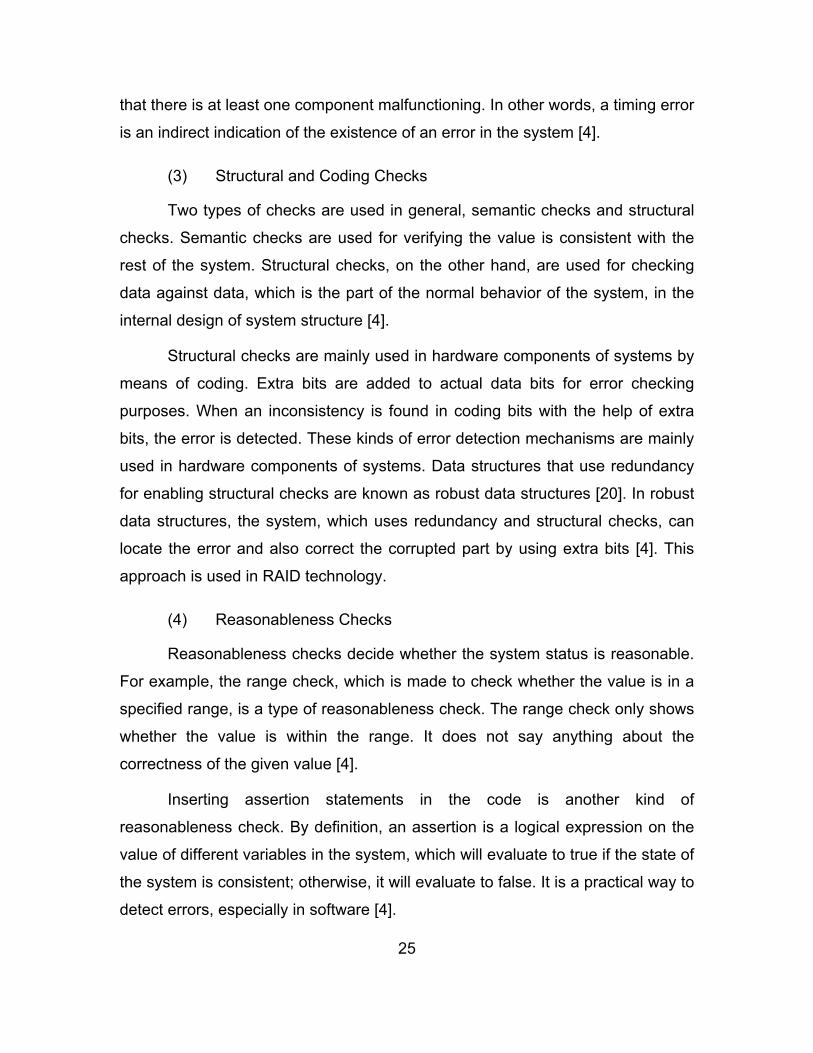
Referring to Figure 6 provides a consolidated view into the inner workings
of Oracle Database 12c. This screenshot is taken from Fernandez’s book [28].
The software tool that was used to generate the screenshot is Spotlight [28]. This
figure gives an insight into many topics that will be discussed in following
sections, such as System Global Area (SGA), Redo logs, Achieve Logs, and
Database Files [28].
34
Figure 6. The Spotlight Tool’s Representation of Oracle Database 12c
Source: I. Fernandez, Beginning Oracle Database 12c Administration: From Novice to Professional, 2nd ed., New York, NY: Apress IOUG, 2015, p. 48.
a. Database vs. Instance
In Oracle terminology, the term of “database” means the physical storage
of data and information, and the term of “instance” means the software that is
running on the server. The instance provides access to the data and information
in the database and the resources that the software uses [29]. Another way to
distinguish the instance from the database is to consider that the instance runs
on the computer or server, and the database resides on hard drives that are
attached to the server or computer [29].

35
The relationship between an instance and a database is presented in
Figure 7.
Figure 7. An Instance and a Database in the Same Figure
Source: R. Greenwald, R. Stackowiak, and J. Stern, Oracle Essentials: Oracle Database 12c, 5th ed. Sebastopol, CA: O’Reilly Media, Inc., 2013, p. 40.
The database is a physical structure. It consists of many files stored on
physical disks. On the other hand, the instance is logical. The instance has
processes on the server [29]. An instance is able to reach only one database.
However, there can be more than one instance in the same database [29].
Oracle has two types of memory areas, the System Global Area (SGA)
and Program Global Area (PGA). The System Global Area (SGA) is an area of
shared memory. The Program Global Area (PGA) is an area of private memory
for each process.

36
b. Data Files and Tablespaces
Data files are collections of files, which are grouped into tablespaces
logically. They have descriptive names, such as DATA, INDEX, UNDO, and
TEMP, in order to indicate the purposes of those files accordingly [28].
All data files have to be stored in tablespaces. A tablespace is a logical
structure. Each tablespace has some physical structures known as data files.
Each tablespace has to have one or more data files. Each data file has to belong
to only one tablespace [29].
c. Control Files
Database control files have the locations of other physical files, which are
data files and redo log files, that form the database. Database control files store
very important information about the database such as [29]:
The name of the database
When the database was created
Names and locations of data files and redo log files
Tablespace information
Data file offline ranges
The log history and current log sequence information
Archived log information
Backup set, pieces, data file, and redo log information
Data file copy information
Checkpoint information [29]
The database control file, which contains the database startup settings,
has two versions that are a pfile (text version) and an spfile (binary version). A
pfile and an spfile have important information such as the memory that the
system will use during its operation [28].
37
Listener.ora is another type of configuration file, which controls the
operation of listener, a process in the database session [28].
Figure 8 shows the relationship among control files, data files, and redo
log files.
Figure 8. Data files, Redo Log files, and Control Files
Source: R. Greenwald, R. Stackowiak, and J. Stern, Oracle Essentials: Oracle Database 12c, 5th ed. Sebastopol, CA: O’Reilly Media, Inc., 2013, p. 43.
d. Redo Log Files
Redo log files hold a log of changes made to databases [29]. Those
changes are results of transactions and internal Oracle activities.
From the fault tolerance perspective, redo log files are vitally important.
When an instance failure occurs, some changes that were made to the database
may not be applied. Redo log files are helpful at those moments; they can be
used to play back the changes and apply them to the database. By doing that,
38
redo log files protect the database by having a fault tolerance to instance failures
[29].
Moreover, redo log files are used for “undo” operations, which are the
following operations after “Rollback.” “Rollback” is basically going back to the last
commit of the database [29].
C. ORACLE DATA GUARD
Oracle Data Guard, its configurations, advantages, and the inner workings
of this technology are discussed in this section.
1. An Overview
According to the official definition from the Oracle white paper, “Oracle
Data Guard is the management, monitoring, and automation software
infrastructure that creates, maintains, and monitors one or more standby
databases to protect enterprise data from failures, disasters, errors, and
corruptions” [21].
The same Oracle white paper adds that
Data Guard maintains these standby databases as synchronized copies of the production database. These standby databases can be located at remote disaster recovery sites thousands of miles away from the production data center, or they may be located in the same city, same campus, or even in the same building. If the production database becomes unavailable because of a planned or an unplanned outage, Data Guard can switch any standby database to the production role, thus minimizing the downtime associated with the outage, and preventing any data loss [22].
2. Oracle Data Guard Configurations
According to [30], “An Oracle Data Guard configuration can contain one
primary database and up to 30 destinations. The members of an Oracle Data
Guard configuration are connected by Oracle Net.” Moreover, Oracle Data Guard
members can be remote from each other; they do not have to be in the same
location [30].
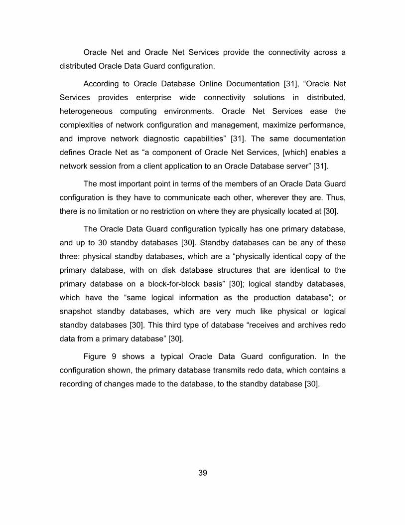
39
Oracle Net and Oracle Net Services provide the connectivity across a
distributed Oracle Data Guard configuration.
According to Oracle Database Online Documentation [31], “Oracle Net
Services provides enterprise wide connectivity solutions in distributed,
heterogeneous computing environments. Oracle Net Services ease the
complexities of network configuration and management, maximize performance,
and improve network diagnostic capabilities” [31]. The same documentation
defines Oracle Net as “a component of Oracle Net Services, [which] enables a
network session from a client application to an Oracle Database server” [31].
The most important point in terms of the members of an Oracle Data Guard
configuration is they have to communicate each other, wherever they are. Thus,
there is no limitation or no restriction on where they are physically located at [30].
The Oracle Data Guard configuration typically has one primary database,
and up to 30 standby databases [30]. Standby databases can be any of these
three: physical standby databases, which are a “physically identical copy of the
primary database, with on disk database structures that are identical to the
primary database on a block-for-block basis” [30]; logical standby databases,
which have the “same logical information as the production database”; or
snapshot standby databases, which are very much like physical or logical
standby databases [30]. This third type of database “receives and archives redo
data from a primary database” [30].
Figure 9 shows a typical Oracle Data Guard configuration. In the
configuration shown, the primary database transmits redo data, which contains a
recording of changes made to the database, to the standby database [30].
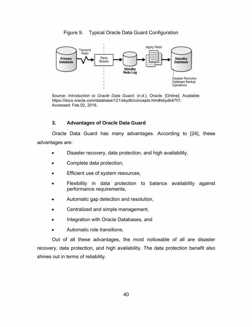
40
Figure 9. Typical Oracle Data Guard Configuration
Source: Introduction to Oracle Data Guard. (n.d.). Oracle. [Online]. Available: https://docs.oracle.com/database/121/sbydb/concepts.htm#sbydb4701. Accessed: Feb.02, 2016.
3. Advantages of Oracle Data Guard
Oracle Data Guard has many advantages. According to [24], these
advantages are:
Disaster recovery, data protection, and high availability,
Complete data protection,
Efficient use of system resources,
Flexibility in data protection to balance availability against performance requirements,
Automatic gap detection and resolution,
Centralized and simple management,
Integration with Oracle Databases, and
Automatic role transitions.
Out of all these advantages, the most noticeable of all are disaster
recovery, data protection, and high availability. The data protection benefit also
shines out in terms of reliability.

41
4. How Data Guard Synchronizes Standby Databases
Primary and standby databases in Oracle Data Guard configuration use
Transmission Control Protocol/Internet Protocol (TCP/IP) to communicate using
Oracle Net Services [23].
According to [23], “Data Guard automatically synchronizes the primary
database and all standby databases by transmitting primary database redo logs”
and applying that information to the standby databases [23].
a. Transport Services
Data guard transport services are responsible for transferring redo log files
from the primary database to standby databases. This can be done automatically
by the system itself, or it can be initiated manually by users. The changes that
are made to the primary database are written to a local online log file via redo log
files. Those redo log files are generated as users commit transactions, which are
made at a primary database. Transport services rapidly transfer those redo log
files from the primary database log buffer to standby databases [30]. There are
two main reasons why this process is very efficient:
Firstly, Data Guard makes a direct transfer from memory, where the redo
log files are allocated and sitting within the system global area, to standby
databases. Therefore, this approach prevents disk input/output overhead on a
primary database [30].
Secondly, Data Guard transmits database redo log files only. Compared to
the other available technology for data protection over physically separate
environments, which is storage remote-mirroring, Data Guard offers a much
more light-weight approach. Recent Oracle tests have shown that Oracle Data
Guard transfers up to 7 times less network volume and 27 times fewer network
input/output operations [30]. Data Guard physical standby prevents input/output
overhead by having logical replication instead of physical replication [30].

42
Remote-mirroring occurs in two ways, synchronous and asynchronous
[30]. Synchronous remote-mirroring is accomplished by staying in communication
with the remote system and waiting for it to finish its writing process. The
recovery point objective of synchronous remote-mirroring is zero data loss, and
the recovery time objective is seconds to minutes. Asynchronous remote-
mirroring, on the other hand, is a store and forward technique [30]. It is mostly
used for cases where there are longer distances between the primary system
and remote systems. On the bright side, both synchronous and asynchronous
remote-mirroring have minimal to zero data loss risk, and they both have a quick
data recovery advantage [32]. However, they are expensive, and they require a
lot of disk space, because the all of the changes that are made to the primary
system must be transmitted as blocks [30], [32].
Data Guard has two transport services: as synchronous and
asynchronous transport services, and synchronous Data Guard transport
services have two options in Oracle Database 12c: Fast Sync and Far Sync [30].
Fast sync enables standby databases to inform the primary database as
soon as they received redo logs. This option improves the overall performance
by decreasing the time for the primary system, waiting for standby system to
finish its commit process [30].
Far sync facilitates zero data loss to standby databases when there is
failover [30]. This is done by making primary database to have the
acknowledgement after successfully commit process in the standby databases.
This option is available in Oracle Active Data Guard [30].
Asynchronous transport services are very much like store and forward
method. In asynchronous transport services, the primary database simply does
not wait for standby databases’ acknowledgements for commit [30].
43
b. Redo Apply Services
According to [30], “Redo Apply services run on a physical standby
database. Redo Apply reads redo records from a standby redo log file, performs
Oracle validation to ensure that redo is not corrupt” [30]. After that, Redo Apply
services apply redo changes to the standby database. Redo apply functions are
independent from transport services [30].
c. Continuous Oracle Verification
Data Guard validates all redo logs before they are committed to the
standby database. Data Guard also detects corruptions that occur because of
lost-writes. Lost-writes primarily result from miscommunication between the
database system and the hard drive. These corruptions may spread from
standby databases to the primary one, or vice versa. Data Guard prevents further
corruptions by performing lost-write validation at standby databases [30].
5. Managing the Data Guard Configuration
The most convenient way to interact with Oracle Database 12c is using
the SQL*Plus application. The SQL*Plus application is available for various
operating systems, including Windows, MAC OS X, and Linux.
Oracle Data Guard can be managed by Data Guard broker, which
“automates and centralizes the creation, maintenance, and monitoring of a Data
Guard configuration” [23]. Database administrators (DBAs) can use either Data
Guard broker’s command line interface or Oracle Enterprise Manager Cloud
Control for interacting the Data Guard broker [23].
Oracle Enterprise Manager Cloud Control is a key product that the Oracle
company uses primarily to provide a complete and integrated enterprise cloud
management solution for information technology management [33]. DBAs use
Oracle Enterprise Manager Cloud Control product via control console. A
screenshot of the Oracle Enterprise Manager Cloud Control console appears in
Figure 10.

44
Figure 10. A Picture of Oracle Enterprise Manager Cloud Control Console
Source: Overview of Oracle Enterprise Manager Cloud Control 12c. (n.d.). Oracle. [Online]. Available: http://docs.oracle.com/cd/E24628_01/doc.121/e25353/overview.htm#EMCON110. Accessed: Feb.09, 2016.
Oracle Enterprise Manager Cloud Control has setup assistants to enable
creating Data Guard configurations. These assistants also simplify the process
for DBAs [23]. The Data Guard management page, which is accessible on Oracle
Enterprise Manager Cloud Control, can be seen in Figure 11.
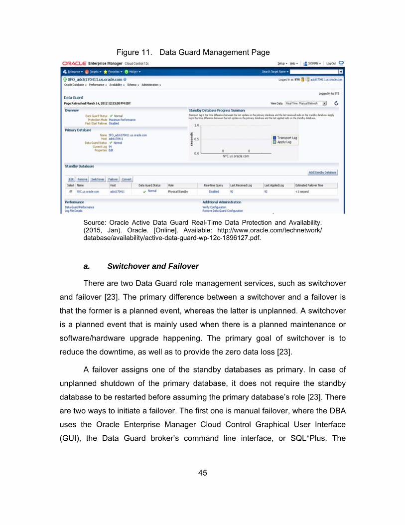
45
Figure 11. Data Guard Management Page
Source: Oracle Active Data Guard Real-Time Data Protection and Availability. (2015, Jan). Oracle. [Online]. Available: http://www.oracle.com/technetwork/database/availability/active-data-guard-wp-12c-1896127.pdf.
a. Switchover and Failover
There are two Data Guard role management services, such as switchover
and failover [23]. The primary difference between a switchover and a failover is
that the former is a planned event, whereas the latter is unplanned. A switchover
is a planned event that is mainly used when there is a planned maintenance or
software/hardware upgrade happening. The primary goal of switchover is to
reduce the downtime, as well as to provide the zero data loss [23].
A failover assigns one of the standby databases as primary. In case of
unplanned shutdown of the primary database, it does not require the standby
database to be restarted before assuming the primary database’s role [23]. There
are two ways to initiate a failover. The first one is manual failover, where the DBA
uses the Oracle Enterprise Manager Cloud Control Graphical User Interface
(GUI), the Data Guard broker’s command line interface, or SQL*Plus. The

46
second way is using fast-start Failover, where Data Guard provides an automatic
failover [23].
b. Fast-Start Failover
Fast-start Failover enables [23] “Data Guard to automatically recover from
a previously chosen standby database without requiring manual intervention to
start the failover process” [23]. In fast-start Failover role, Data Guard also
“continuously monitors the status of the configuration and initiates a failover if
needed” [23].
c. Automating Client Failover
Although manual failover and fast-start failover are very important
capabilities, they are not enough by themselves. In order to have an efficient high
availability, all running processes and applications should be able to kill their
existing transactional processes to or from the failed primary database, and
direct themselves by quickly reconnecting to the new primary database [23].
According to [23], Data Guard broker can automatically assign a “standby
database to the primary role,” start “required database services appropriately for
the primary role,” and notify “application clients to disconnect from the failed
primary database.” Broker can also direct application clients to the new primary
database, without requiring any further manual actions [23].
6. Tying Data Guard to Fault Tolerance
As discussed in Chapter II, there are four fault tolerance stages, which are
error detection, damage confinement, error recovery, and fault treatment and
continued system service.
Error detection is done by DGMGRL and Observer in the Data Guard
Configuration. DGMGRL monitors the status of the configuration and tells
whether the configuration is successful, DGMGRL gives details if the
configuration is not successful. Observer monitors the fast-start failover
47
configuration and detects any errors in the primary database to perform an
automatic failover to the standby database. Observer also automatically
reinstates the primary database when it is up again.
Damage confinement is done and mitigated primarily by having redo log
files, transport services, and flashback database in the Data Guard. Switchover
and failover operations also contribute to the damage confinement stage.
Error recovery is provided by restoring or reinstating the failed database to
an earlier state. The earlier state used for reinstatement is stored in the flashback
database. The error recovery strategy in Oracle Data Guard is the backward
recovery.
Fault treatment and continued system service is achieved by the
combined efforts of redo log files, flashback databases, switchover and failover
operations, and transport services. They all contribute to fault treatment and
continued system service stage. However, the error removal from the system or
databases requires manual interventions.
D. ORACLE VM VIRTUALBOX
Oracle VM Virtualbox and its capabilities are discussed in this section.
1. An Overview
“Oracle VM VirtualBox is a cross-platform virtualization application” [34]. It
is installed on the existing operating system. It also boosts the capabilities of the
existing computer “so that it can run multiple operating systems at the same time”
[34]. There is no limitation on the number of virtual machines to run using Oracle
VM VirtualBox, except the disk space and the memory [34].
2. Capabilities and Technical Aspects
Here are the main features of Oracle VM VirtualBox application:
Portability: According to [34] “VirtualBox runs on a large number of 32-bit and 64-bit host operating systems, such as Windows, Mac, Linux, and Solaris.” Oracle VM VirtualBox is a “hosted” hypervisor
48
(type 2). The overview in [34] continues that Oracle VM VirtualBox “requires an existing operating system to be installed. It can thus run alongside existing applications on that host” [34]. Oracle VM VirtualBox is “functionally identical on all of the host platforms, and the same file and image formats are used. This allows you to run virtual machines created on one host on another host with a different host operating system; for example, a virtual machine that is created on Mac, can also run under Linux” [34].
Compatibility with the existing hardware capabilities of the host computer: Users can use Oracle VM VirtualBox with some old hardware, where new features are not present [34].
Extended hardware support: Oracle VM VirtualBox supports guest multiprocessing, USB device support, hardware compatibility with the existing hardware capabilities of the host computer, full Advanced Configuration and Power Interface (ACPI) support, multiscreen resolutions, built-in Internet Small Computer System Interface (iSCSI) support, and Preboot Execution Environment (PXE) Network boot [34].
Remote machine display: The Oracle VM VirtualBox Remote Desktop Extension (VRDE) offers “high-performance remote access to any running virtual machine. This extension supports the Remote Desktop Protocol (RDP) originally built into Microsoft Windows, with special additions for full client USB support” [34].
Oracle VM VirtualBox runs on the following operating systems [34]:
Windows hosts:
Windows Vista SP1 and later (32-bit and 64-bit)
Windows Server 2008 (64-bit)
Windows Server 2008 R2 (64-bit)
Windows 7 (32-bit and 64-bit)
Windows 8 (32-bit and 64-bit)
Windows 8.1 (32-bit and 64-bit)
Windows 10 RTM build 10240 (32-bit and 64-bit)
Windows Server 2012 (64-bit)

49
Windows Server 2012 R2 (64-bit)
Mac OS X hosts (64-bit):
10.8 (Mountain Lion)
10.9 (Mavericks)
10.10 (Yosemite)
10.11 (El Capitan)
Linux hosts (32-bit and 64-bit):
Ubuntu 10.04 to 15.04
Debian GNU/Linux 6.0 (“Squeeze”) and 8.0 (“Jessie”)
Oracle Enterprise Linux 5, Oracle Linux 6 and 7
Redhat Enterprise Linux 5, 6 and 7
Fedora Core / Fedora 6 to 22
Gentoo Linux
openSUSE 11.4, 12.1, 12.2, 13.
Mandriva 2011
Solaris hosts (64-bit only):
Solaris 11
Solaris 10 (U10 and higher)

50
THIS PAGE INTENTIONALLY LEFT BLANK
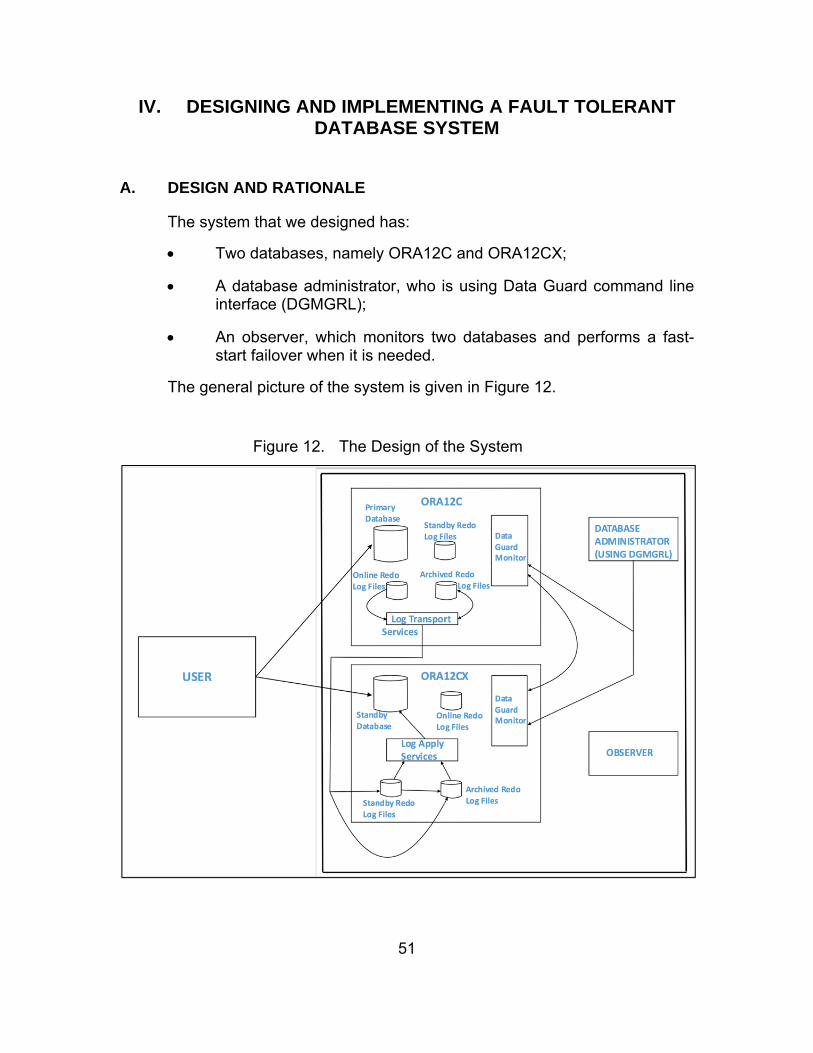
51
IV. DESIGNING AND IMPLEMENTING A FAULT TOLERANT DATABASE SYSTEM
A. DESIGN AND RATIONALE
The system that we designed has:
Two databases, namely ORA12C and ORA12CX;
A database administrator, who is using Data Guard command line interface (DGMGRL);
An observer, which monitors two databases and performs a fast-start failover when it is needed.
The general picture of the system is given in Figure 12.
Figure 12. The Design of the System
So
52
The assumptions for the system that we designed derive from the actual
needs of C2 systems in naval warfare ships. According to the U.S. Department of
Defense Dictionary of Military and Associated Terms, the C2 system provides
“…facilities, equipment, communications, procedures, and personnel essential
for a commander to plan, direct, and control operations of assigned and attached
forces pursuant to the missions assigned” [35].
C2 systems have to meet two minimum requirements, which are
establishing and keeping the secure communication with the remote command
authorities, and providing effective and correct supportive information to the
captain and the officers in charge in the combat information center on a ship in a
timely manner.
The design of the research system is focused on meeting the needs of the
ship’s interior information system that consistently supports the C2 system. That
is the main reason why we chose to store the databases and other elements in
the same operating system.
Our system uses the primary database, which is ORA12C, when
everything is normal and there is no failure in the system. This means, ORA12C
is the primary means of storing the information that supports the C2 system.
When there is no fault (i.e., the primary database is up, running, and accessible
to the other services), data will directly go to the primary database and our
system will update the standby database in real time. Since both the primary and
the standby databases are synchronized with the help of Oracle Data Guard
architecture, the system itself will offer the redundancy by having the same data
in multiple databases and places in the disk.
Having a problem in the standby database will not affect the actual
transaction on the primary database and in the C2 system. The database
managers will be informed of the problem in the standby database, and they can
work on the problem without interfering with the active primary database. Oracle

53
Data Guard will sense and start storing changes in the primary database in redo
log files until the future time when the standby database will be up and running.
When there is a problem encountered in the primary database, the system
will perform a switch to the standby database. The standby database will take the
responsibility of the primary database from that moment on until the database
administrator fixes the problem in the primary database. After the standby
database alters its role as primary, all changes will be stored on the standby
database.
The database administrator can perform a switchover between two
databases when there is a need. The need for switchover can be:
Planned maintenance in the primary database;
Planned maintenance on the primary database’s hardware;
Renewal of network cables in the primary database;
Training purposes.
The database administrator can also perform a failover between two
databases. The motives for failover can be:
An unexpected problem or failure occurs in the primary database;
An unexpected problem occurs on the primary database’s hardware;
A connection is lost or a network failure occurs;
A need for training requires it.
The Data Guard is also capable of performing a failover when there is no
available database administrator on duty, or to limit the down time of the system
before the failover that is performed by the database administrator. The
observer’s primary job is to monitor the activities of the system and intervene
when needed.
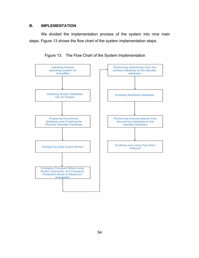
54
B. IMPLEMENTATION
We divided the implementation process of the system into nine main
steps. Figure 13 shows the flow chart of the system implementation steps.
Figure 13. The Flow Chart of the System Implementation
So

55
1. Implementation Steps
First, we selected the Fedora operating system as the working
environment because it is a stable and secure version of Linux. Furthermore, the
Fedora operating system is a readily available operating system, which is free
and open-source licensed. We also picked the VirtualBox application because it
is a free hypervisor capable of hosting many operating systems, including
Fedora. After setting up the initial environment, we started the second step of the
implementation, which was installing Oracle Database 12c on Fedora operating
system. The details of installing Oracle Database 12c on Fedora operating
system is explained in the Appendix.
The third step was preparing the primary database and creating the
physical standby database. According to [30], “physical standby database is kept
synchronized with the primary database by using Redo Log files.” We modified
tnsnames and listener files in order to enable the primary database to talk to the
standby database. After creating required directories, the password file, and the
initialization parameter file for the standby database, we started up the standby
instance and then ran the RMAN script for duplicating the primary to the standby.
The fourth step was configuring the Data Guard Broker. Data Guard
Broker is a “framework that automates and centralizes the creation,
maintenance, and monitoring the Data Guard configurations” [36]. This manages
the entire Data Guard configuration including redo transport services, log apply
services, switchovers, and failovers. In this step, we added DGMGRL listeners
for each of the databases by using netmgr. We added ORA12C as the primary
database and ORA12CX as the physical standby database in the DGMGRL
configuration.
The fifth step was changing transport and protection modes. We changed
the transport mode to synchronous using the Broker properties. Data Guard
Transport Services are responsible for transferring redo log files from the primary
to the standby database. We selected synchronous redo transport mode in our

56
system to make sure that the primary database waits for confirmation from the
standby database when it sends redo log files. We also picked the protection
mode as maximum availability to ensure that the primary database waits until it
receives acknowledgement for applying redo log files from the standby or the
timeout threshold expires. By selecting this mode, we emphasized availability as
the first priority and the second priority as zero data loss protection.
The sixth step was performing a switchover from the primary database to
the standby database. The key advantage of the switchover operation is no
matter which transport service and protection mode are used, it always offers a
zero data loss transition from the primary database to the standby database.
The seventh step was enabling the flashback database. The flashback
database allows the database administrator and Data Guard configuration to
“reinstate a failed primary database as a standby database after a failover
occurred” [36].
The eighth step was performing a manual failover from the primary
database to the standby database. This step was done to show how our system
would react to an unexpected failure in the primary database. The expected
actions for the standby database are taking the responsibility of the primary role
and keeping the system running. This step was done manually from the
DGMGRL console.
The last step was enabling and using fast-start failover. As described by
[36], this allows the Data Guard configuration to automatically perform a failover
to a standby database without needing a manual input or action from the
database administrator. This goal is achieved by using the Observer, which
according to [36] “continuously monitors the status of fast-start failover
configuration.” The Observer also automatically reinstates the failed primary
database after the primary database is up again [36].
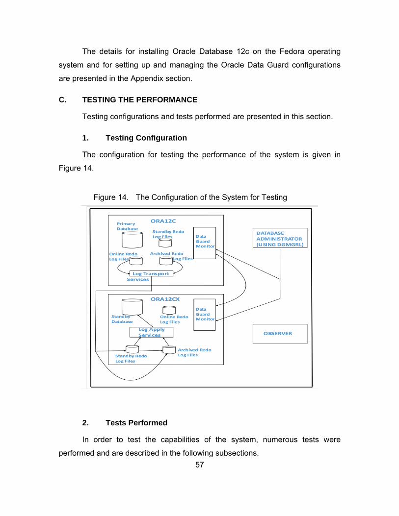
57
The details for installing Oracle Database 12c on the Fedora operating
system and for setting up and managing the Oracle Data Guard configurations
are presented in the Appendix section.
C. TESTING THE PERFORMANCE
Testing configurations and tests performed are presented in this section.
1. Testing Configuration
The configuration for testing the performance of the system is given in
Figure 14.
Figure 14. The Configuration of the System for Testing
So
2. Tests Performed
In order to test the capabilities of the system, numerous tests were
performed and are described in the following subsections.
58
a. Connectivity
The connectivity test was performed to verify that both databases were up
and running. In this test, we started up the listener, primary database (ORA12C),
standby database (ORA12CX), and the observer before running Java codes. We
also connected the primary database (ORA12C) using the DGMGRL to check
the current configuration of the system.
We followed the following sequence of events during the connectivity
testing scenario:
1. The primary database (ORA12C), the standby database (ORA12CX), and the observer were started.
2. The configuration of the system was checked by using DGMGRL.
3. The system configuration status was checked to confirm it as “SUCCESS.”
4. Another terminal was opened prior to running the Java code for the connectivity testing.
5. TestDBConnection.java code was run to check the connectivity of the primary database (ORA12C).
6. TestDBConnection2.java code was run to check the connectivity of the standby database (ORA12CX).
b. User Creation and Granting Roles
The user creation and granting roles test was performed in order to check
what happens when the database administrator creates a user in the primary
database, grants some roles to that user, and creates a table named test, by
connecting to the system as that user. In this test, we started up the listener,
primary database (ORA12C), standby database (ORA12CX), and the observer
before running the test. We also connected the primary database (ORA12C)
using the DGMGRL to check the current configuration of the system.
We followed the following sequence of events during the user creation and
granting roles testing scenario:
59
1. The primary database (ORA12C), the standby database (ORA12CX), and the observer were started.
2. The configuration of the system was checked by using DGMGRL.
3. The system configuration status was checked to confirm it as “SUCCESS.”
4. A new user, named “c##kadir,” was created in the primary database in the SQL*Plus command line. Required grants were given to the user “c##kadir” in order to create a table, add to, update, and delete from the table.
5. A connection to the primary database (ORA12C) was established with the newly created user “c##kadir.”
6. A new table, named “test,” was created. One column was created for testing purposes in the “test” table. Five entries were inserted into the “test” table.
7. After completing the creating the user, granting roles, creating a table using that user’s credentials, and inserting some values into that table, a new terminal was opened to connect to the standby database (ORA12CX).
8. A connection to the primary database (ORA12C) was established with the recently created user “c##kadir.”
9. The “test” table and all entries were verified in the standby database (ORA12CX) using the user “c##kadir” credentials.
c. Reading from Databases
The reading from databases test was performed in order to confirm that
the table count numbers in both databases were the same. In this test, we
started up the listener, primary database (ORA12C), standby database
(ORA12CX), and the observer before running the test. We also connected the
primary database (ORA12C) using the DGMGRL to check the current
configuration of the system.
We followed the following sequence of events during the reading from
databases testing scenario:
1. The primary database (ORA12C), the standby database (ORA12CX), and the observer were started.
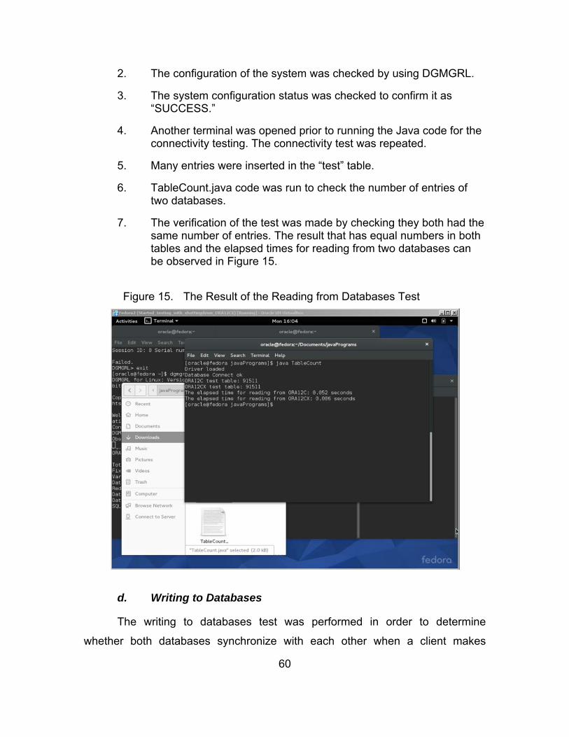
60
2. The configuration of the system was checked by using DGMGRL.
3. The system configuration status was checked to confirm it as “SUCCESS.”
4. Another terminal was opened prior to running the Java code for the connectivity testing. The connectivity test was repeated.
5. Many entries were inserted in the “test” table.
6. TableCount.java code was run to check the number of entries of two databases.
7. The verification of the test was made by checking they both had the same number of entries. The result that has equal numbers in both tables and the elapsed times for reading from two databases can be observed in Figure 15.
Figure 15. The Result of the Reading from Databases Test
So
d. Writing to Databases
The writing to databases test was performed in order to determine
whether both databases synchronize with each other when a client makes
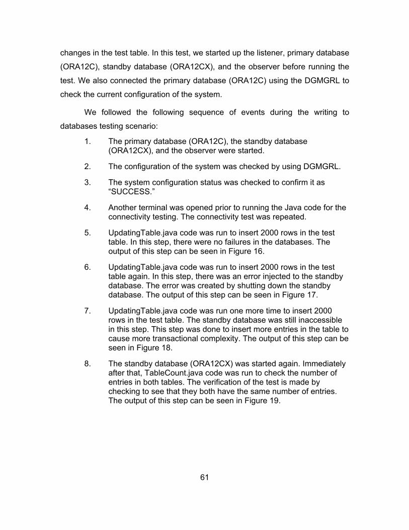
61
changes in the test table. In this test, we started up the listener, primary database
(ORA12C), standby database (ORA12CX), and the observer before running the
test. We also connected the primary database (ORA12C) using the DGMGRL to
check the current configuration of the system.
We followed the following sequence of events during the writing to
databases testing scenario:
1. The primary database (ORA12C), the standby database (ORA12CX), and the observer were started.
2. The configuration of the system was checked by using DGMGRL.
3. The system configuration status was checked to confirm it as “SUCCESS.”
4. Another terminal was opened prior to running the Java code for the connectivity testing. The connectivity test was repeated.
5. UpdatingTable.java code was run to insert 2000 rows in the test table. In this step, there were no failures in the databases. The output of this step can be seen in Figure 16.
6. UpdatingTable.java code was run to insert 2000 rows in the test table again. In this step, there was an error injected to the standby database. The error was created by shutting down the standby database. The output of this step can be seen in Figure 17.
7. UpdatingTable.java code was run one more time to insert 2000 rows in the test table. The standby database was still inaccessible in this step. This step was done to insert more entries in the table to cause more transactional complexity. The output of this step can be seen in Figure 18.
8. The standby database (ORA12CX) was started again. Immediately after that, TableCount.java code was run to check the number of entries in both tables. The verification of the test is made by checking to see that they both have the same number of entries. The output of this step can be seen in Figure 19.

62
Figure 16. Inserting 2000 Rows When Both Databases Are Up
So
Figure 17. Inserting 2000 Rows When the Standby Database Is Down

63
Figure 18. Inserting 2000 More Rows When the Standby Database Is Down
So
Figure 19. Two Databases Are Synchronized
So
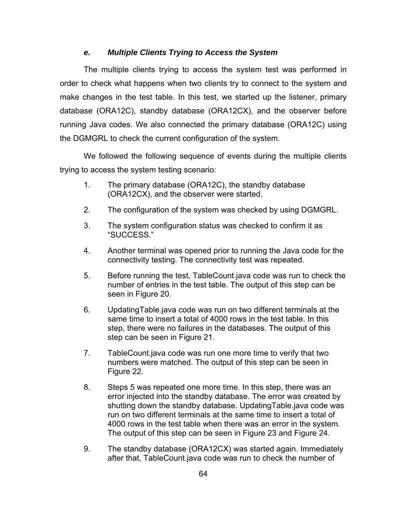
64
e. Multiple Clients Trying to Access the System
The multiple clients trying to access the system test was performed in
order to check what happens when two clients try to connect to the system and
make changes in the test table. In this test, we started up the listener, primary
database (ORA12C), standby database (ORA12CX), and the observer before
running Java codes. We also connected the primary database (ORA12C) using
the DGMGRL to check the current configuration of the system.
We followed the following sequence of events during the multiple clients
trying to access the system testing scenario:
1. The primary database (ORA12C), the standby database (ORA12CX), and the observer were started.
2. The configuration of the system was checked by using DGMGRL.
3. The system configuration status was checked to confirm it as “SUCCESS.”
4. Another terminal was opened prior to running the Java code for the connectivity testing. The connectivity test was repeated.
5. Before running the test, TableCount.java code was run to check the number of entries in the test table. The output of this step can be seen in Figure 20.
6. UpdatingTable.java code was run on two different terminals at the same time to insert a total of 4000 rows in the test table. In this step, there were no failures in the databases. The output of this step can be seen in Figure 21.
7. TableCount.java code was run one more time to verify that two numbers were matched. The output of this step can be seen in Figure 22.
8. Steps 5 was repeated one more time. In this step, there was an error injected into the standby database. The error was created by shutting down the standby database. UpdatingTable.java code was run on two different terminals at the same time to insert a total of 4000 rows in the test table when there was an error in the system. The output of this step can be seen in Figure 23 and Figure 24.
9. The standby database (ORA12CX) was started again. Immediately after that, TableCount.java code was run to check the number of

65
entries in both tables. The verification of the test is made by checking to see that they both have the same number of entries. The output of this step can be seen in Figure 25.
Figure 20. The Output Before Running Step 6
Figure 21. Inserting 4000 Rows from Two Different Terminals
So
66
Figure 22. Two Databases Are Synchronized
So
Figure 23. The Output Before Running Step 8
So
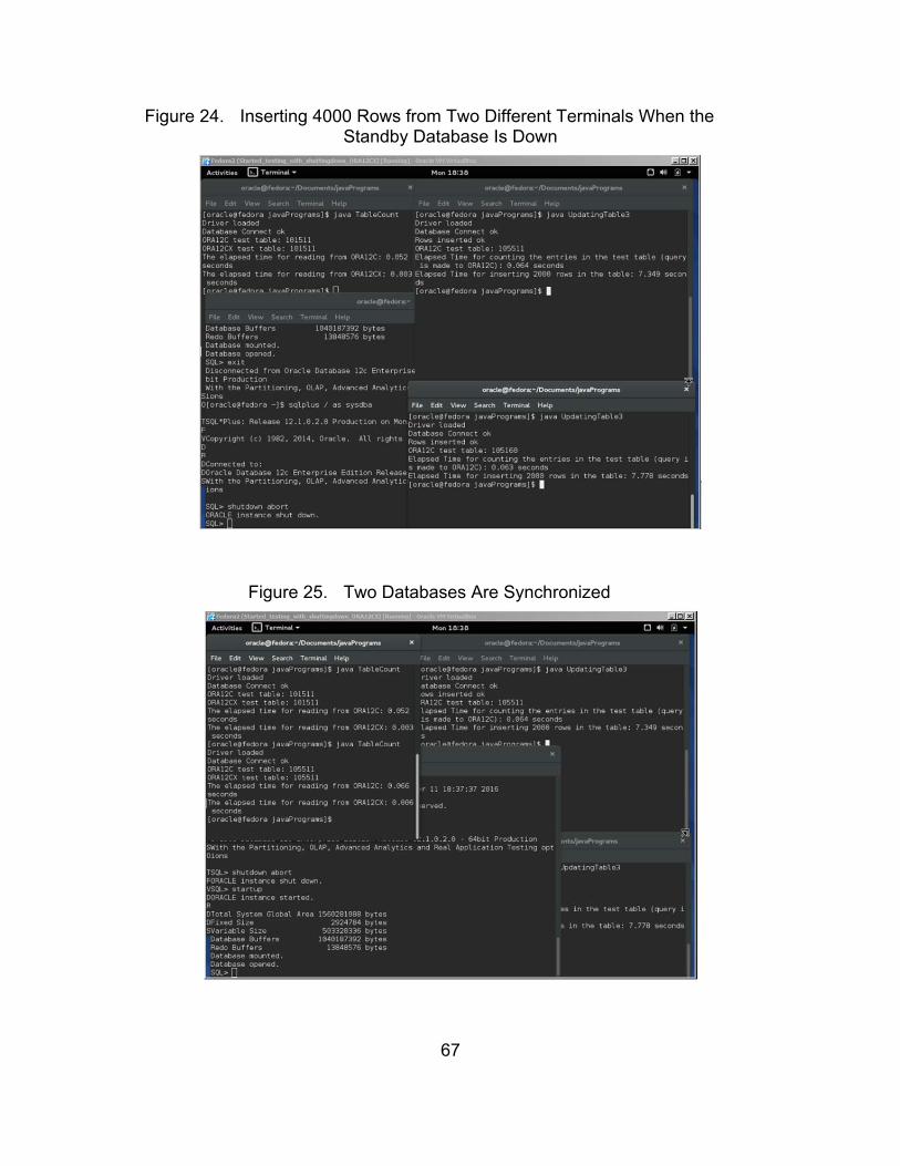
67
Figure 24. Inserting 4000 Rows from Two Different Terminals When the Standby Database Is Down
So
Figure 25. Two Databases Are Synchronized
So
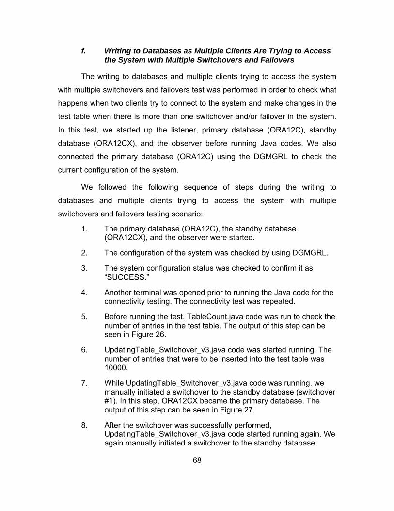
68
f. Writing to Databases as Multiple Clients Are Trying to Access the System with Multiple Switchovers and Failovers
The writing to databases and multiple clients trying to access the system
with multiple switchovers and failovers test was performed in order to check what
happens when two clients try to connect to the system and make changes in the
test table when there is more than one switchover and/or failover in the system.
In this test, we started up the listener, primary database (ORA12C), standby
database (ORA12CX), and the observer before running Java codes. We also
connected the primary database (ORA12C) using the DGMGRL to check the
current configuration of the system.
We followed the following sequence of steps during the writing to
databases and multiple clients trying to access the system with multiple
switchovers and failovers testing scenario:
1. The primary database (ORA12C), the standby database (ORA12CX), and the observer were started.
2. The configuration of the system was checked by using DGMGRL.
3. The system configuration status was checked to confirm it as “SUCCESS.”
4. Another terminal was opened prior to running the Java code for the connectivity testing. The connectivity test was repeated.
5. Before running the test, TableCount.java code was run to check the number of entries in the test table. The output of this step can be seen in Figure 26.
6. UpdatingTable_Switchover_v3.java code was started running. The number of entries that were to be inserted into the test table was 10000.
7. While UpdatingTable_Switchover_v3.java code was running, we manually initiated a switchover to the standby database (switchover #1). In this step, ORA12CX became the primary database. The output of this step can be seen in Figure 27.
8. After the switchover was successfully performed, UpdatingTable_Switchover_v3.java code started running again. We again manually initiated a switchover to the standby database

69
(switchover #2). In this step, ORA12C became the primary database. The output of this step can be seen in Figure 28.
9. We repeated the step 7 (switchover #3). The output of this step can be seen in Figure 29.
10. We repeated the step 8 (switchover #4). The output of this step can be seen in Figure 30.
11. UpdatingTable_Switchover_v3.java code finished running. The verification of the test is made by checking the number of entries in the system before and after running UpdatingTable_Switchover_v3.java code. We saw the number of entries was 10000 more in comparison to the previous number, which we had in Step 5. The output of this step can be seen in Figure 31.
12. The same steps 5 through 11 were run one more time with UpdatingTable_Switchover_v4.java code. In this version of the code, there were no printout statements. The verification of the test is made by checking the number of entries in the system before and after running UpdatingTable_Switchover_v4.java code. We saw the number of entries was 10000 more in comparison to the previous number before running the code. The output of this step can be seen in Figure 32.
13. After finishing the having multiple switchovers while inserting into the test table, we run the same test with two UpdatingTable_Switchover_v3.java codes running at the same time as multiple threads. Before running the test, TableCount.java code was run to check the number of entries in the test table. The output of this step can be seen in Figure 33.
14. Two UpdatingTable_Switchover_v3.java codes were started running at the same time. The number of entries to be inserted into the test table was 20000 in total.
15. While UpdatingTable_Switchover_v3.java codes were running, we manually initiated a switchover to the standby database (switchover #1). In this step, ORA12CX became the primary database. The output of this step can be seen in Figure 34.
16. After the switchover was successfully performed, UpdatingTable_Switchover_v3.java codes started running again. We again manually initiated a switchover to the standby database (switchover #2). In this step, ORA12C became the primary database. The output of this step can be seen in Figure 35.

70
17. We repeated the step 14 (switchover #3). The output of this step can be seen in Figure 36.
18. We repeated the step 15 (switchover #4). The output of this step can be seen in Figure 37.
19. UpdatingTable_Switchover_v3.java codes finished running. The verification of the test is made by checking the number of entries in the system before and after running UpdatingTable_Switchover_v3.java codes. We saw the number of entries was 20000 more compared to the previous number, which we had in Step 12. The output of this step can be seen in Figure 38.
20. The same steps 13 through 19 were run one more time with UpdatingTable_Switchover_v4.java code. In this version of the code, there were no printout statements. The verification of the test is made by checking the number of entries in the system before and after running UpdatingTable_Switchover_v4.java code. We saw the number of entries were 20000 more compared to the previous number before running the code. The output of this step can be seen in Figure 39.
21. After finishing the having multiple switchovers while inserting into the test table with multiple threads, we ran another test to evaluate the behavior of the system when there is a failover. Before running the test, TableCount.java code was run to check the number of entries in the test table. The output of this step can be seen in Figure 40.
22. Two UpdatingTable_Switchover_v3.java codes were started running at the same time. The number of entries to be inserted into the test table was 20000 in total. As they were running, we injected an error in the system by manually shutting down the primary database (ORA12C). The observer sensed the error in 30 seconds and initiated a failover to the standby database (ORA12CX). After the failover, the two threads started running once again. After waiting a couple of seconds, we manually started up the ORA12C instance. The observer started reinstating ORA12C as the two threads were running.
23. UpdatingTable_Switchover_v3.java codes finished running. The verification of the test is made by checking the number of entries in the system before and after running UpdatingTable_Switchover_v3.java codes. We saw the number of entries was 20001 more compared to the previous number, which we had in Step 19. The output of this step can be seen in Figure 41.

71
24. Lastly, we ran the same test with UpdatingTable_Switchover_v4.java code, which had no printout statements. The verification of the test is made by checking the number of entries in the system before and after running UpdatingTable_Switchover_v4.java codes. We saw the number of entries was 20001 more compared to the previous number before running the code. The output of this step can be seen in Figure 42.
Figure 26. The Number of Entries in the Test Table Before Running the Four Switchovers in a Single Thread Test
So
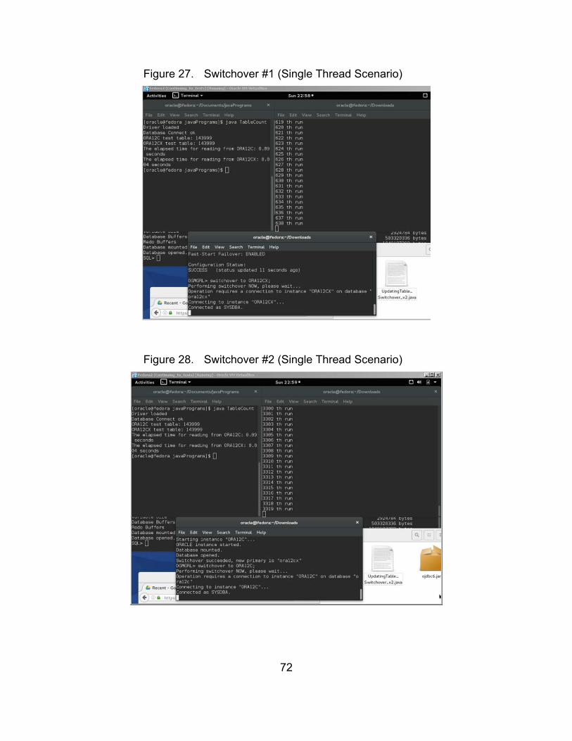
72
Figure 27. Switchover #1 (Single Thread Scenario)
So
Figure 28. Switchover #2 (Single Thread Scenario)
So

73
Figure 29. Switchover #3 (Single Thread Scenario)
So
Figure 30. Switchover #4 (Single Thread Scenario)
So

74
Figure 31. The End of Four Switchovers in a Single Thread Test
So
Figure 32. The End of Four Switchovers in a Single Thread Test (No Printout Statements)
So

75
Figure 33. The Number of Entries in the Test Table Before Running the Four Switchovers in Multiple Threads Test
So
Figure 34. Switchover #1 (Multiple Threads Scenario)
So
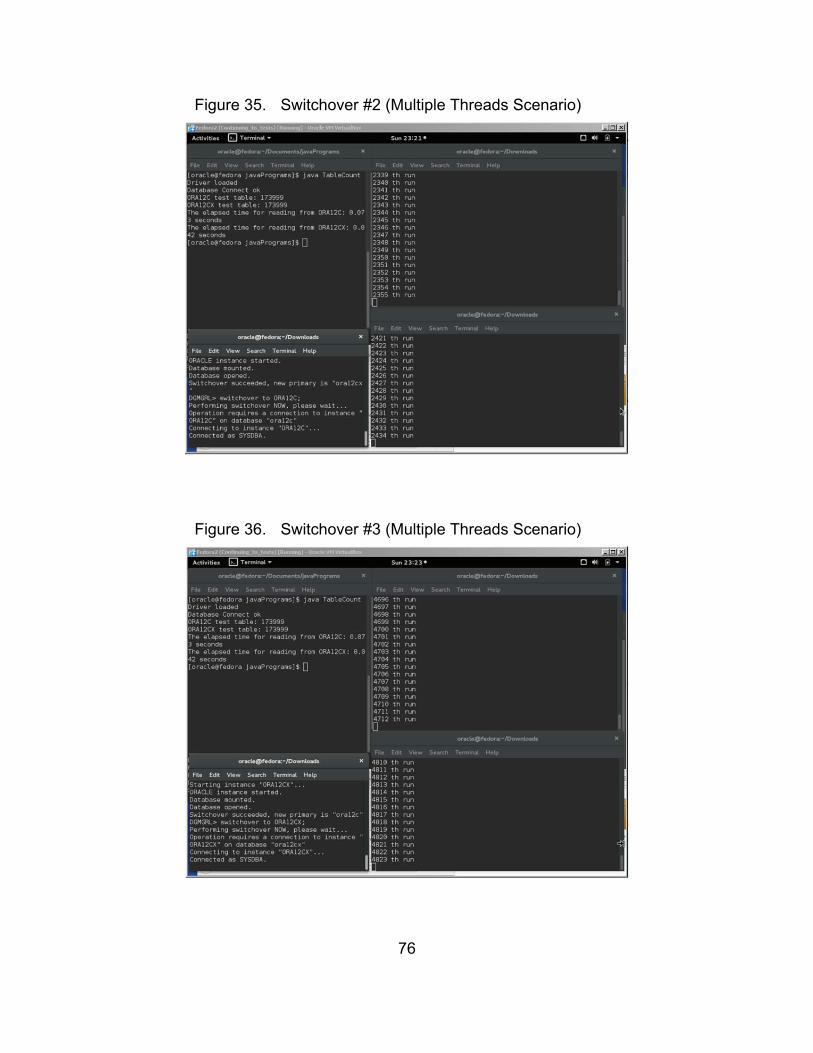
76
Figure 35. Switchover #2 (Multiple Threads Scenario)
So
Figure 36. Switchover #3 (Multiple Threads Scenario)
So

77
Figure 37. Switchover #4 (Multiple Threads Scenario)
So
Figure 38. The End of Four Switchovers in Multiple Threads Test
So
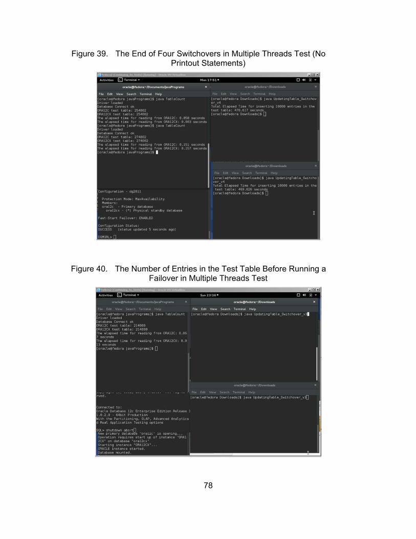
78
Figure 39. The End of Four Switchovers in Multiple Threads Test (No Printout Statements)
So
Figure 40. The Number of Entries in the Test Table Before Running a Failover in Multiple Threads Test
So
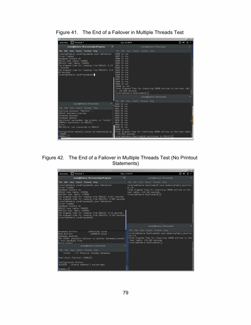
79
Figure 41. The End of a Failover in Multiple Threads Test
So
Figure 42. The End of a Failover in Multiple Threads Test (No Printout Statements)
So
80
D. REVIEWING TEST RESULTS
There were six different tests performed in order to assess the
functionality of the system. Those were connectivity, user creation and granting
roles, reading from databases, writing to databases, multiple clients trying to
access the system, and writing to databases as multiple clients are trying to
access the system with multiple switchovers and failovers.
In the connectivity test, the expected outcome was that the system is up,
running, and accessible. The expected result was met in this test.
In the user creation and granting roles test, the expected outcome was to
see that when a user was created and granted some roles in one database, the
same user was created in the other database. For this test, we created a user
“c##kadir” in the primary database with permissions for creating a table, adding
to it, updating, and deleting from the table. We also created a “test” table for that
user. We observed that the same user was created in the other database with
the “test” table. The expected result was met in this test.
In the reading from databases test, the expected outcome was to see the
same number of entries in both databases’ “test” tables. This test was performed
when two databases were up, running, and accessible. We observed that after
inserting some entries into the primary database’s “test” table, the two databases
synchronized with each other and the total number of entries in both “test” tables
stayed the same. It took 0.052 seconds to read the number of entries in the “test”
table from the primary database (ORA12C) and 0.006 seconds from the standby
database (ORA12CX), respectively. The expected result was met in this test.
In the writing to databases test, the expected outcome was to see the
same number of entries in both databases’ “test” tables after inserting some
entries in the primary database when the standby database was shut down. First,
we inserted 2000 entries into the primary database’s “test” table when the
standby database was up. It took 9.9 seconds to insert 2000 entries. After
inserting 2000 entries in the primary database’s “test” table, we observed that

81
both databases had the same number of entries, which also meant that they
were synchronized as expected. Second, we inserted 4000 entries into the
primary database’s “test” table when the standby database was shut down. It
took 12 seconds to insert 4000 entries in the primary database’s “test” table.
After inserting 4000 entries in the primary database’s “test” table, we started up
the standby database. It took 11.5 seconds for the standby database to start up
and get ready. After that, we observed that both databases had the same
number of entries, which also meant that they were synchronized as expected.
The expected result was met in this test.
In the multiple clients trying to access the system test, the expected
outcome was to see the system responded to all clients that were trying to
connect to databases and updating the “test” table. The expected outcome was
also to see the same number of entries in both databases. In this test, we ran two
Java codes that inserted 2000 entries each in the “test” table simultaneously from
two terminals. We also performed the same test with a failure in the standby
database. After inserting the total of 4000 entries in the primary database’s “test”
table, we observed that both databases had the same number of entries, which
also meant that they were synchronized as expected. It took 8 seconds to insert
4000 entries in the primary database’s “test” table. It took 11.5 seconds for the
standby database to start up and get ready. The expected result was met in this
test.
In the writing to databases as multiple clients are trying to access the
system with multiple switchovers and failovers test, the expected outcome was to
see the system responded to all clients that were trying to connect to databases
and updating the “test” table. The expected outcome was also to see the same
number of entries in both databases. In this test, we first ran one java code that
inserted 10000 entries in the “test” table as there were four switchovers that
happened in the system. It took 420 seconds to insert 10000 entries in the
system as the four switchovers occurred. The same test was also run one more

82
time with no printout statements. This time, it took 358 seconds to insert 10000
entries in the system as four switchovers occurred.
Next, we ran two Java codes that inserted 20000 entries in the “test” table
simultaneously from two terminals as there were four switchovers occurring in
the system. It took 584 seconds to insert 20000 entries in the system as four
switchovers occurred. The same test was also run one more time with no printout
statements. This time, it took 470 seconds to insert 20000 entries in the system
as four switchovers occurred.
Lastly, we ran two Java codes that inserted 20000 entries in the “test”
table simultaneously from two terminals as one failover happened in the system.
The observer was able to sense the error approximately 30 seconds after we
manually shut down the primary database (ORA12C). It took 122 seconds to
insert 20000 entries in the system as one failover occurred. The same test was
also run one more time with no printout statements. This time, it took 119
seconds to insert 20000 entries in the system as one failover occurred. In the
failover scenario, we observed that there was one more entry in the databases.
This was a normal system behavior in maximum availability mode according to
data protection definitions as described in Data Guard Protection Modes [30].
In all three scenarios in which multiple clients are trying to access the
system with multiple switchovers and failovers, the expected number of entries
was observed after the performed tests. The expected results were met in those
tests.
We have made another observation regarding the switchover and failover
durations. It took 45 seconds to perform a switchover and 75 seconds to perform
a failover. This observation also agrees with Client Failover Best Practices for
Highly Available Oracle Databases [37].

83
V. CONCLUSIONS AND FUTURE WORK
A. SUMMARY
The purpose of this thesis is to find an alternative way for ensuring the
fault tolerance in C2 systems of naval platforms. It is highly critical for C2
systems of naval platforms to be robust to failures.
This thesis primarily focused on the databases of C2 systems, which
provide all required data to operators, officers, and the captains in order to help
them make decisions using their technical knowledge combined with detailed
scientific information. The data that are stored in these databases can vary in a
high spectrum. The data can simply be the velocity and the direction of the wind,
which can be expressed by integers or floats, or be sophisticated information of
the weapons on board.
In this thesis, we showed that there is a potentially cheaper way to provide
a fault tolerant mechanism for C2 database systems. We designed and
implemented a system using Oracle Database 12c Enterprise Edition and its
features. Specifically, we used two databases in the system, ORA12C and
ORA12CX. Then we connected those two databases with the Data Guard
capability.
Six different tests were performed to check the capabilities and
performance of the system. We observed that all expected results were met and
the system behaved in accordance with the fault tolerance objectives.
Our experiments showed that there is a way to have a robust, fast, and
fault tolerant system for storing databases of C2 systems by using a virtual
environment rather than a physical redundancy. Our alternative approach also
can decrease the cost of having multiple of redundant servers that store
databases. This approach can be used in many fields such as small businesses
and large enterprises that require a fault tolerant solution for physical, human-

84
made, design, and interaction faults. The military domain can also take
advantage of the approach presented in this work.
B. FUTURE WORK
This thesis makes the initial effort to ensure fault tolerance by working in a
virtual environment. The system that we designed here can be tested with the
data flow in a real C2 system of a naval platform as a future work idea.
The framework in this thesis is stored in the same virtual machine by using
the local machine’s connections to simulate the C2 system database that is
physically located on the ship. The next step can be installing and modifying a
fault tolerant system in distant locations, thus enabling a redundant off-site
database system that can function as a means of backup as well as a fault-
tolerant node.

85
APPENDIX
A. INSTALLING ORACLE DATABASE 12C ON FEDORA OPERATING SYSTEM
In this appendix, we describe how we installed Oracle Database 12c on
the Fedora operating system, which runs on the Virtual Box application. We
primarily used the http://dbaora.com/install-oracle-12c-release-1-12-1-on-fedora-
22/ website, which is included in the references section.
First, we downloaded the Oracle Database 12c software from the official
Oracle website (http://www.oracle.com/technetwork/database/enterprise-edition/
downloads/index.html). Before installing the software on the operating system,
we made sure that the operating system was updated to the latest version
properly by entering “dnf update” command in the command line.
The groups and users that were used for installing the database are given
here:
“#groups for database management groupadd -g 54321 oinstall groupadd -g 54322 dba groupadd -g 54323 oper groupadd -g 54324 backupdba groupadd -g 54325 dgdba groupadd -g 54326 kmdba groupadd -g 54327 asmdba groupadd -g 54328 asmoper groupadd -g 54329 asmadmin #users for database management useradd -u 54321 -g oinstall -G dba,oper,backupdba,dgdba,kmdba oracle”
After choosing the password for our database, we checked to see which
packets were missing for the installation of the database by typing in the
command line as follows:
“rpm -q --qf ‘%{NAME}-%{VERSION}-%{RELEASE}(%{ARCH})\n’ binutils
\compat-libstdc++-33 \gcc \gcc-c++ \glibc \glibc-common \glibc-devel \glibc-
headers \ksh \libaio \libaio-devel \libgcc \libstdc++ \libstdc++-devel \libXext
86
\libXtst \libX11 \libXau \libXi \make \sysstat \unixODBC \unixODBC-devel \zlib-
devel”
After figuring out the missing packets, we downloaded and installed them
on the operating system. We added and applied the kernel parameters, which
are recommended by Oracle, to the operating system. All of these given
parameters were written into “/etc/sysctl.conf” file as follows:
“--kernel parameters for 12gR1 installation fs.file-max = 6815744 kernel.sem = 250 32000 100 128 kernel.shmmni = 4096 kernel.shmall = 1073741824 kernel.shmmax = 4398046511104 net.core.rmem_default = 262144 net.core.rmem_max = 4194304 net.core.wmem_default = 262144 net.core.wmem_max = 1048576 fs.aio-max-nr = 1048576 net.ipv4.ip_local_port_range = 9000 65500 /sbin/sysctl –p”
The recommended shell limits for the Oracle user were written into “/etc/
security/limit.conf” file as follows:
“--shell limits for users oracle 12gR1 oracle soft nofile 1024 oracle hard nofile 65536 oracle soft nproc 2047 oracle hard nproc 16384 oracle soft stack 10240 oracle hard stack 32768”
In order to make the installation more user-friendly and more hassle-free,
we disabled the SELINUX, which is “a reference implementation of the Flask
security architecture for flexible mandatory access control. It was created to
demonstrate the value of flexible mandatory access controls and how such
controls could be added to an operating system” [38].
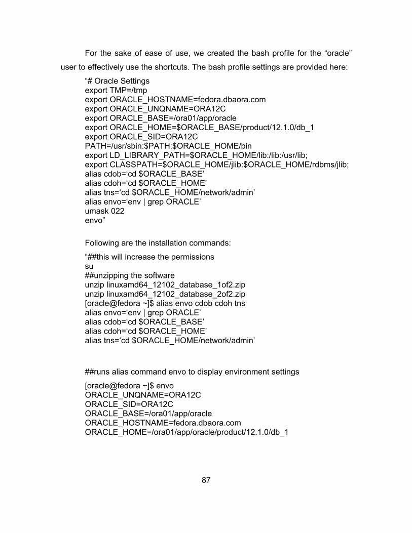
87
For the sake of ease of use, we created the bash profile for the “oracle”
user to effectively use the shortcuts. The bash profile settings are provided here:
“# Oracle Settings export TMP=/tmp export ORACLE_HOSTNAME=fedora.dbaora.com export ORACLE_UNQNAME=ORA12C export ORACLE_BASE=/ora01/app/oracle export ORACLE_HOME=$ORACLE_BASE/product/12.1.0/db_1 export ORACLE_SID=ORA12C PATH=/usr/sbin:$PATH:$ORACLE_HOME/bin export LD_LIBRARY_PATH=$ORACLE_HOME/lib:/lib:/usr/lib; export CLASSPATH=$ORACLE_HOME/jlib:$ORACLE_HOME/rdbms/jlib; alias cdob=‘cd $ORACLE_BASE’ alias cdoh=‘cd $ORACLE_HOME’ alias tns=‘cd $ORACLE_HOME/network/admin’ alias envo=‘env | grep ORACLE’ umask 022 envo”
Following are the installation commands:
“##this will increase the permissions su ##unzipping the software unzip linuxamd64_12102_database_1of2.zip unzip linuxamd64_12102_database_2of2.zip [oracle@fedora ~]$ alias envo cdob cdoh tns alias envo=‘env | grep ORACLE’ alias cdob=‘cd $ORACLE_BASE’ alias cdoh=‘cd $ORACLE_HOME’ alias tns=‘cd $ORACLE_HOME/network/admin’
##runs alias command envo to display environment settings
[oracle@fedora ~]$ envo ORACLE_UNQNAME=ORA12C ORACLE_SID=ORA12C ORACLE_BASE=/ora01/app/oracle ORACLE_HOSTNAME=fedora.dbaora.com ORACLE_HOME=/ora01/app/oracle/product/12.1.0/db_1

88
##runs alias command cdob and cdoh to check ORACLE_BASE,
ORACLE_HOME
[oracle@fedora ~]$ cdob
[oracle@fedora oracle]$ pwd
/ora01/app/oracle
[oracle@fedora db_1]$ cdoh
[oracle@fedora db_1]$ pwd
/ora01/app/oracle/product/12.1.0/db_1
##finally runs the installation
./runInstaller”
After this step, an installation window of the Oracle Database 12c was
displayed on the screen. There are total of 21 steps in the installation wizard.
During the installation progress, we selected “Server class” and “Single instance
database installation” with the “Enterprise Edition” of Oracle Databases. We also
gave “ORA12C” as my database Oracle System Identifier (SID). We specified the
“Unicode” as the character set for the installation for enabling storage of multiple
language groups. The database was installed in the directory “/ora01/app/oracle/
product/12.1.0/db_1/.” The Oracle Enterprise Manager Database Express 12c
can access the database that we installed by typing
“https://fedora.dbaora.com:5500/em” on the web browser.
These steps were done for one database installation on the Fedora
operating system.
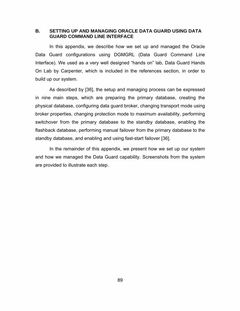
89
B. SETTING UP AND MANAGING ORACLE DATA GUARD USING DATA GUARD COMMAND LINE INTERFACE
In this appendix, we describe how we set up and managed the Oracle
Data Guard configurations using DGMGRL (Data Guard Command Line
Interface). We used as a very well designed “hands on” lab, Data Guard Hands
On Lab by Carpenter, which is included in the references section, in order to
build up our system.
As described by [36], the setup and managing process can be expressed
in nine main steps, which are preparing the primary database, creating the
physical database, configuring data guard broker, changing transport mode using
broker properties, changing protection mode to maximum availability, performing
switchover from the primary database to the standby database, enabling the
flashback database, performing manual failover from the primary database to the
standby database, and enabling and using fast-start failover [36].
In the remainder of this appendix, we present how we set up our system
and how we managed the Data Guard capability. Screenshots from the system
are provided to illustrate each step.

90
1. Preparing the Primary Database
Figures 43 through 46 are given for preparing the primary database step.
Figure 43. Enabling Archiving and Force Logging
Source: “O
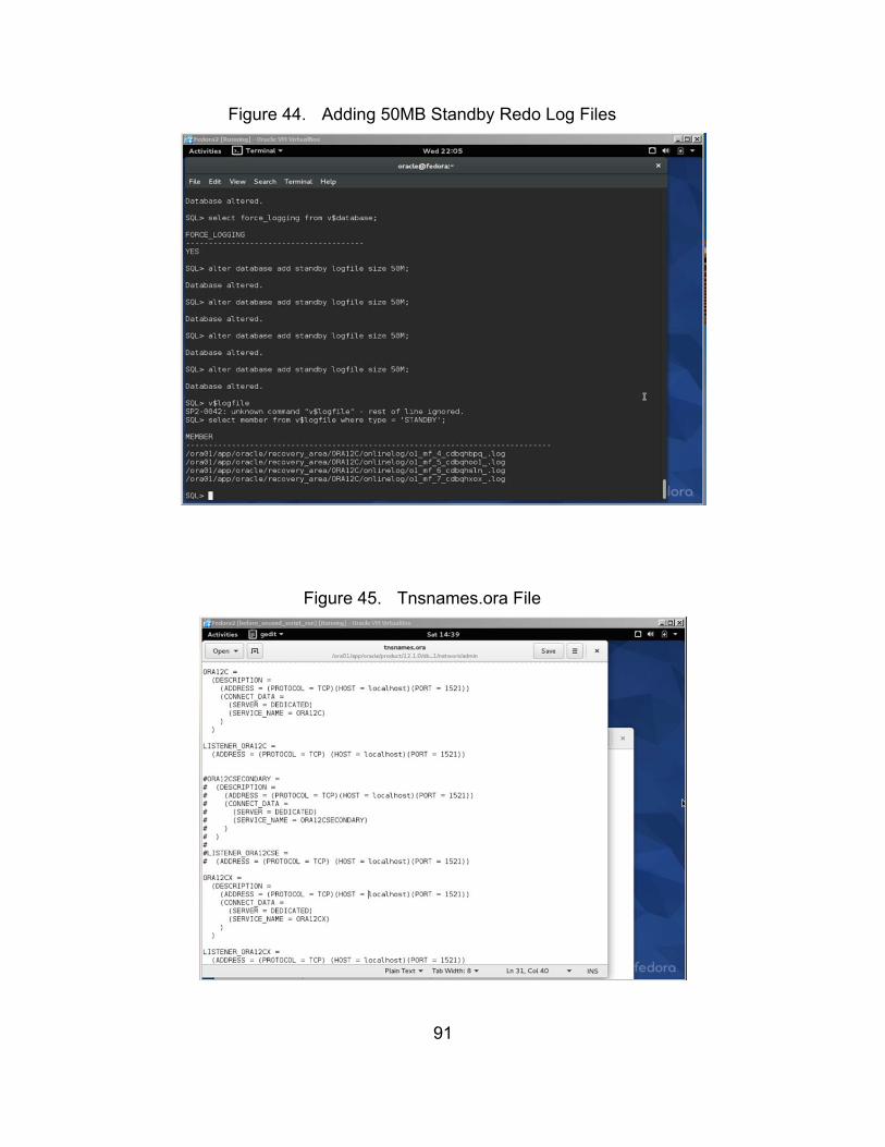
91
Figure 44. Adding 50MB Standby Redo Log Files
Source: “O
Figure 45. Tnsnames.ora File
Source: “O

92
Figure 46. Listener.ora File
Source: “O

93
2. Creating the Physical Standby Database
Figures 47 and Figure 48 are given for preparing the primary database
step.
Figure 47. Creating Required Directories for the Standby Database
Source: “O
Figure 48. RMAN Script that Duplicates the Primary to the Standby
Source: “O
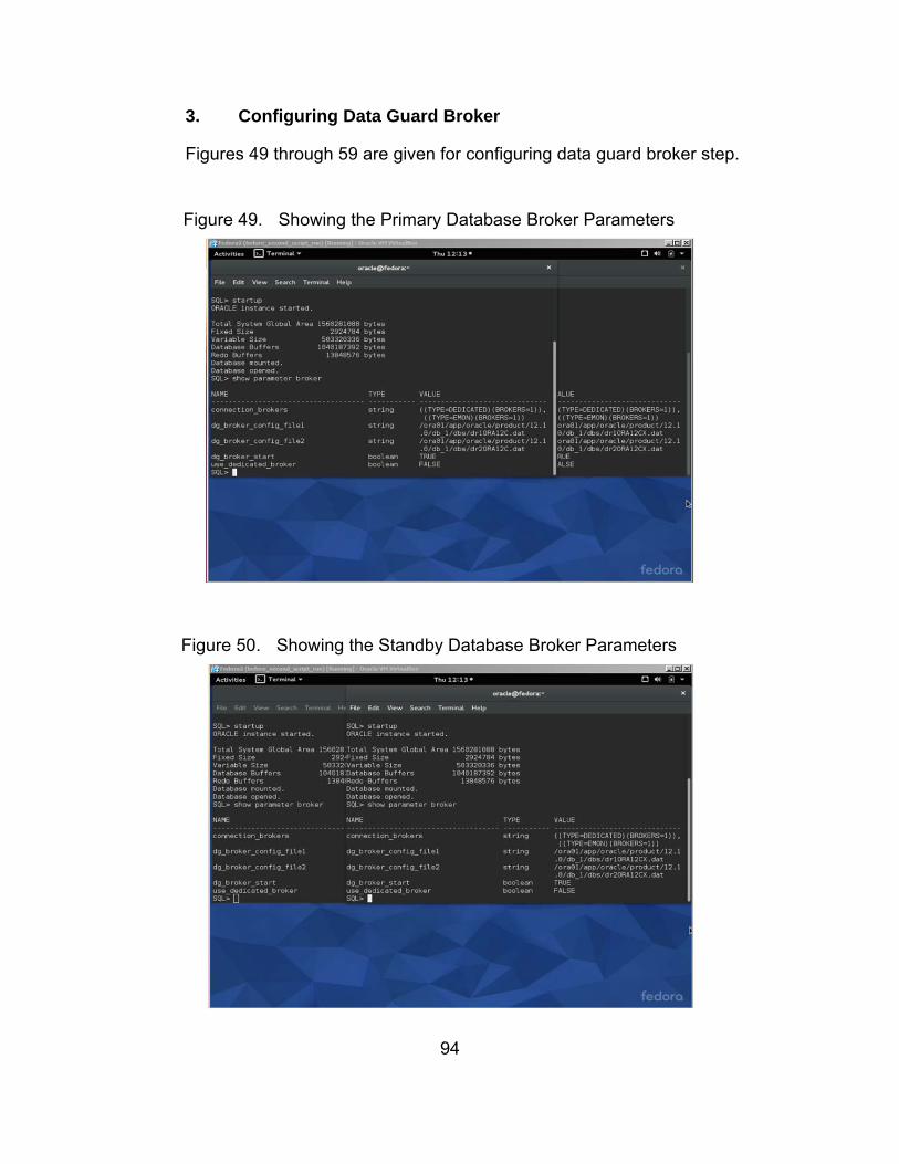
94
3. Configuring Data Guard Broker
Figures 49 through 59 are given for configuring data guard broker step.
Figure 49. Showing the Primary Database Broker Parameters
Source: “O
Figure 50. Showing the Standby Database Broker Parameters
Source: “O

95
Figure 51. Creating the Broker Configurations-I
Source: “O
Figure 52. Creating the Broker Configurations-II
Source: “O

96
Figure 53. Creating the Broker Configurations-III
Source: “O
Figure 54. Showing the Primary Database Properties-I
Source: “O

97
Figure 55. Showing the Primary Database Properties-II
Source: “O
Figure 56. Showing the Standby Database Properties-I
Source: “O
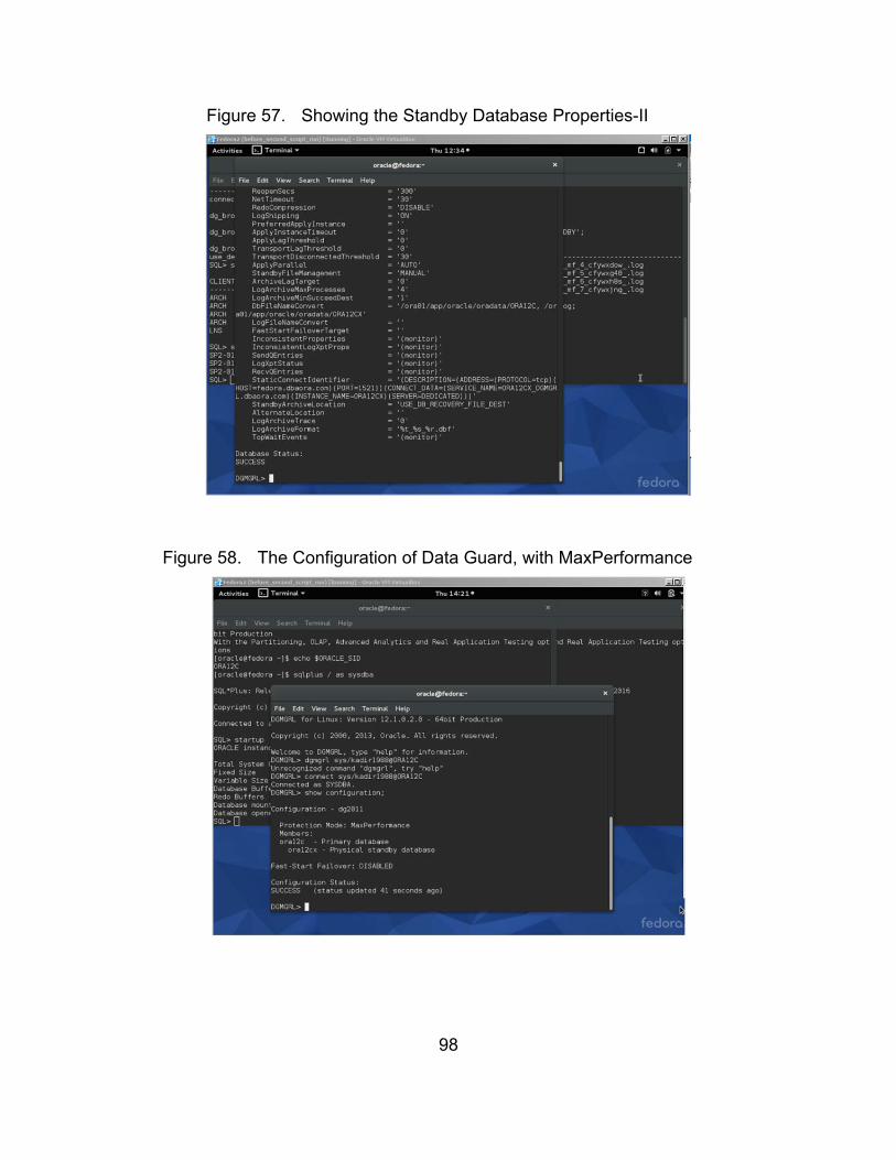
98
Figure 57. Showing the Standby Database Properties-II
Source: “O
Figure 58. The Configuration of Data Guard, with MaxPerformance
Source: “O

99
Figure 59. The Configuration of Data Guard, with MaxAvailability
Source: “O
4. Changing Transport Mode Using Broker Properties
Figures 60 through 65 are given for changing transport mode using broker
properties step.
Figure 60. Showing the Initial Transport Method
Source: “O
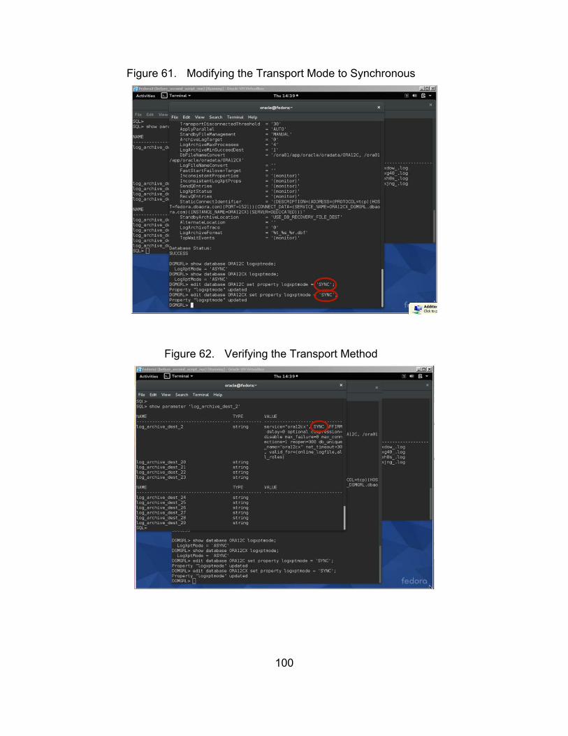
100
Figure 61. Modifying the Transport Mode to Synchronous
Source: “O
Figure 62. Verifying the Transport Method
Source: “O

101
Figure 63. Creating a Redo Gap Between Primary and Standby
Source: “O
Figure 64. Restarting the Standby Database
Source: “O
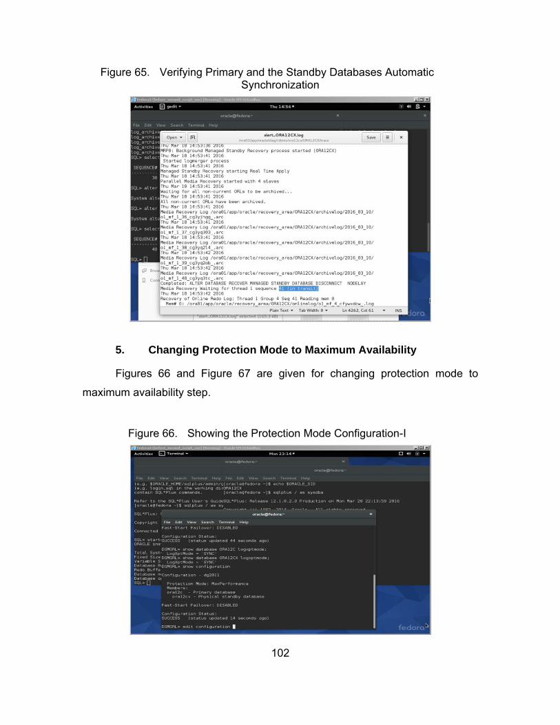
102
Figure 65. Verifying Primary and the Standby Databases Automatic Synchronization
Source: “O
5. Changing Protection Mode to Maximum Availability
Figures 66 and Figure 67 are given for changing protection mode to
maximum availability step.
Figure 66. Showing the Protection Mode Configuration-I
Source: “O
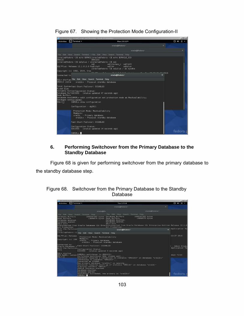
103
Figure 67. Showing the Protection Mode Configuration-II
Source: “O
6. Performing Switchover from the Primary Database to the Standby Database
Figure 68 is given for performing switchover from the primary database to
the standby database step.
Figure 68. Switchover from the Primary Database to the Standby Database
Source: “O

104
7. Enabling Flashback Database
Figures 69 through 72 are given for enabling flashback database step.
Figure 69. Showing Parameters for Flashback Database
Source: “O

105
Figure 70. Enabling Flashback Database on Both Databases-I
Source: “O
Figure 71. Enabling Flashback Database on Both Databases-II
Source: “O

106
Figure 72. Enabling Flashback Database on Both Databases-III
Source: “O
8. Performing Manual Failover from the Primary Database to the Standby Database
Figures 73 through 79 are given for performing manual failover from the
primary database to the standby database step.
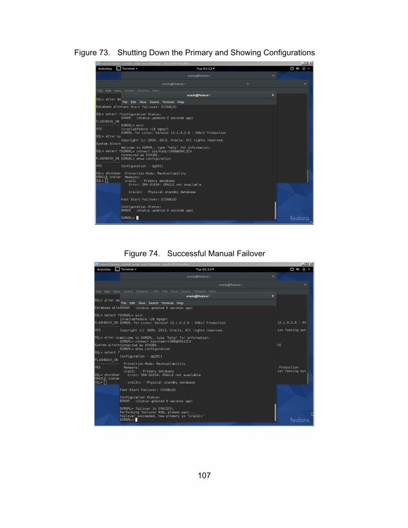
107
Figure 73. Shutting Down the Primary and Showing Configurations
Source: “O
Figure 74. Successful Manual Failover
Source: “O

108
Figure 75. Verifying that the Standby Database Became the Primary
Source: “O
Figure 76. Starting Up the Standby Database (Previously the Primary)
Source: “O

109
Figure 77. The Broker Initiates Reinstatement of Database that Shut Down Unexpectedly
Source: “O
Figure 78. Success after Reinstating the Database that Shut Down Unexpectedly
Source: “O
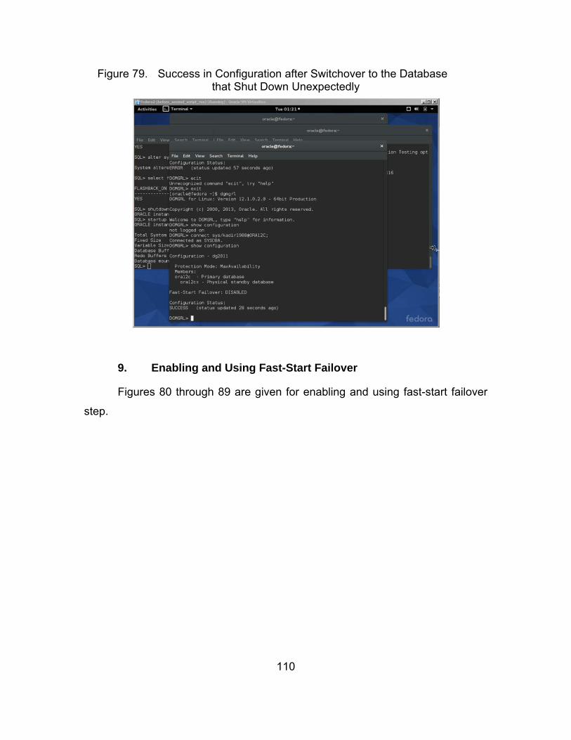
110
Figure 79. Success in Configuration after Switchover to the Database that Shut Down Unexpectedly
Source: “O
9. Enabling and Using Fast-Start Failover
Figures 80 through 89 are given for enabling and using fast-start failover
step.
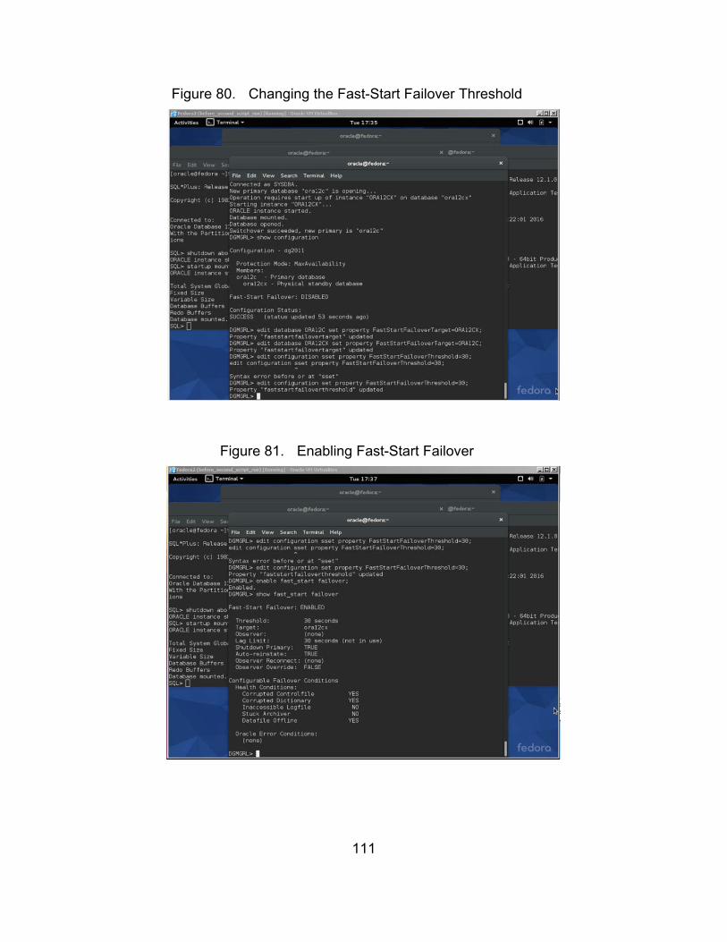
111
Figure 80. Changing the Fast-Start Failover Threshold
Source: “O
Figure 81. Enabling Fast-Start Failover
Source: “O
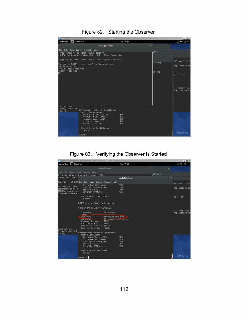
112
Figure 82. Starting the Observer
Source: “O
Figure 83. Verifying the Observer Is Started
Source: “O

113
Figure 84. Shutting Down the Primary Database for Fast-Start Failover
Source: “O
Figure 85. Examining the Actions in the Observer during the Fast-Start Failover
Source: “O

114
Figure 86. The Configuration after Fast-Start Failover
Source: “O
Figure 87. Restarting the Previous Primary Database
Source: “O
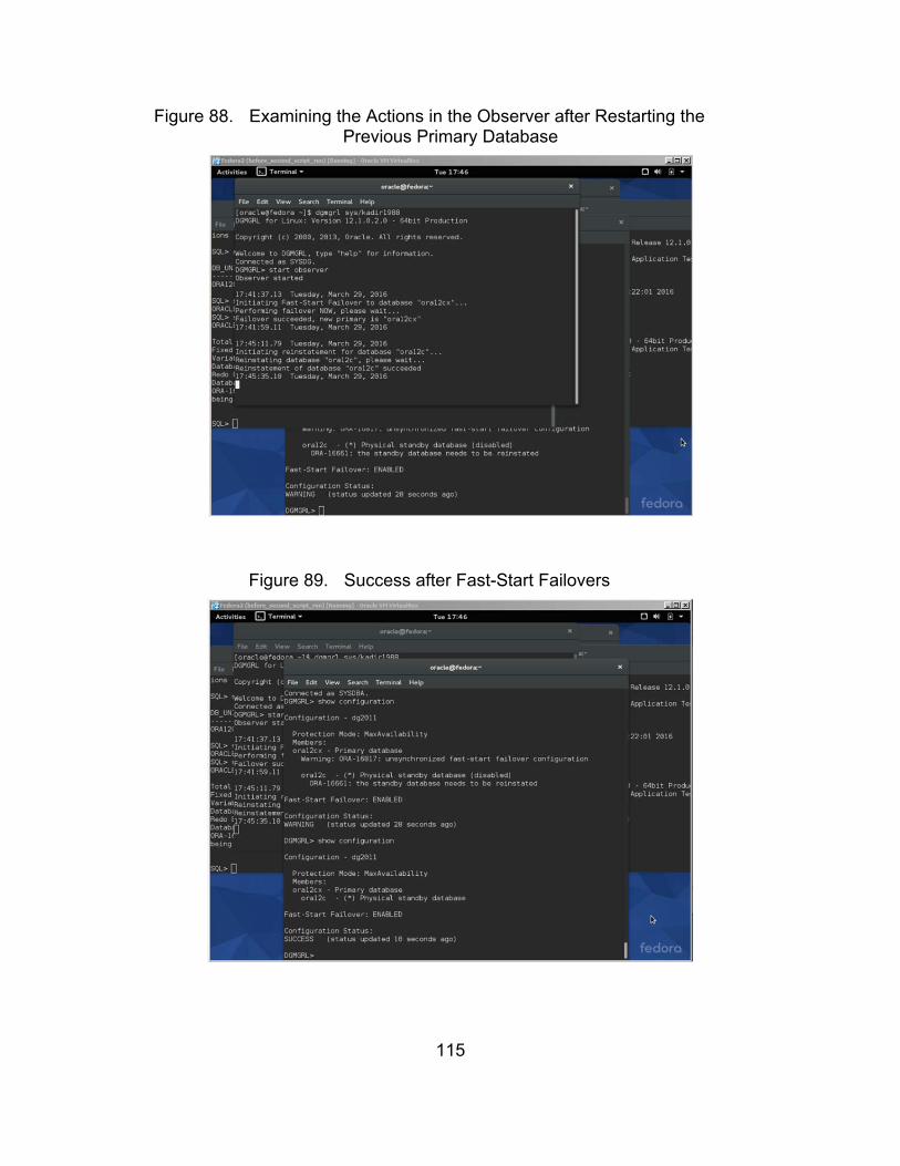
115
Figure 88. Examining the Actions in the Observer after Restarting the Previous Primary Database
Source: “O
Figure 89. Success after Fast-Start Failovers
Source: “O

116
THIS PAGE INTENTIONALLY LEFT BLANK

117
LIST OF REFERENCES
[1] J. C. Laprie, “Dependable computing and fault tolerance: Concepts and terminology,” in Proceedings of FTCS-25, Pasadena, CA, 1995, vol. 3, pp. 2–11.
[2] IEEE Standard Glossary of Software Engineering Terminology, ANSI/IEEE Std. 610.12, 1990.
[3] P. K. Pradhan, Fault-Tolerant Computer System Design, 1st ed. Upper Saddle River, NJ: Prentice-Hall, 1996.
[4] P. Jalote, Fault Tolerance in Distributed Systems, 2nd ed. Englewood Cliffs, NJ: PTR Prentice Hall, 1998.
[5] E. Kati, “Fault-tolerant approach for deploying server agent-based active network management (SAAM) server in Windows NT environment to provide uninterrupted services to routers in case of server failure(s),” M.S. thesis, Dept. Computer Science, Naval Postgraduate School, Monterey, CA, 2000.
[6] I. Koren and C. M. Krishna, Fault-Tolerant Systems, San Francisco, CA: Morgan Kaufmann, 2007.
[7] D. Duggan, “Type-based hot swapping of running modules (extended abstract),” in Proceedings of the Sixth ACM SIGPLAN International Conference on Functional Programming—ICFP ‘01, Florence, Italy, 2001, pp. 62–73.
[8] Feng, N., et al. “Dynamic evolution of network management software by software hot-swapping,” presented at IEEE/IFIP International Symposium on Integrated Network Management Proceedings, Seattle, WA, 2001, pp. 63–76.
[9] Q. Wang, J. Shen, X. Wang, and H. Mei, “A component-based approach to online software evolution,” Journal of Software Maintenance and Evolution: Research and Practice, vol. 18, no. 3, pp. 181–205, May and Jun. 2006.
[10] D. A. Patterson, G. Gibson, and R. H. Katz, “A case for redundant arrays of inexpensive disks (RAID),” in ACM SIGMOD Record SIGMOD Rec., vol. 17, no. 3, pp. 109–116, 1988.
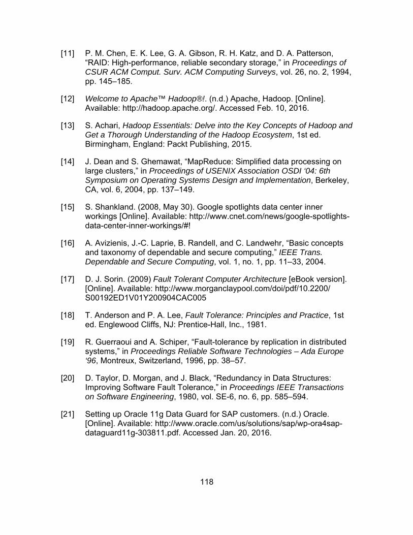
118
[11] P. M. Chen, E. K. Lee, G. A. Gibson, R. H. Katz, and D. A. Patterson, “RAID: High-performance, reliable secondary storage,” in Proceedings of CSUR ACM Comput. Surv. ACM Computing Surveys, vol. 26, no. 2, 1994, pp. 145–185.
[12] Welcome to Apache™ Hadoop®!. (n.d.) Apache, Hadoop. [Online]. Available: http://hadoop.apache.org/. Accessed Feb. 10, 2016.
[13] S. Achari, Hadoop Essentials: Delve into the Key Concepts of Hadoop and Get a Thorough Understanding of the Hadoop Ecosystem, 1st ed. Birmingham, England: Packt Publishing, 2015.
[14] J. Dean and S. Ghemawat, “MapReduce: Simplified data processing on large clusters,” in Proceedings of USENIX Association OSDI ‘04: 6th Symposium on Operating Systems Design and Implementation, Berkeley, CA, vol. 6, 2004, pp. 137–149.
[15] S. Shankland. (2008, May 30). Google spotlights data center inner workings [Online]. Available: http://www.cnet.com/news/google-spotlights-data-center-inner-workings/#!
[16] A. Avizienis, J.-C. Laprie, B. Randell, and C. Landwehr, “Basic concepts and taxonomy of dependable and secure computing,” IEEE Trans. Dependable and Secure Computing, vol. 1, no. 1, pp. 11–33, 2004.
[17] D. J. Sorin. (2009) Fault Tolerant Computer Architecture [eBook version]. [Online]. Available: http://www.morganclaypool.com/doi/pdf/10.2200/S00192ED1V01Y200904CAC005
[18] T. Anderson and P. A. Lee, Fault Tolerance: Principles and Practice, 1st ed. Englewood Cliffs, NJ: Prentice-Hall, Inc., 1981.
[19] R. Guerraoui and A. Schiper, “Fault-tolerance by replication in distributed systems,” in Proceedings Reliable Software Technologies – Ada Europe ‘96, Montreux, Switzerland, 1996, pp. 38–57.
[20] D. Taylor, D. Morgan, and J. Black, “Redundancy in Data Structures: Improving Software Fault Tolerance,” in Proceedings IEEE Transactions on Software Engineering, 1980, vol. SE-6, no. 6, pp. 585–594.
[21] Setting up Oracle 11g Data Guard for SAP customers. (n.d.) Oracle. [Online]. Available: http://www.oracle.com/us/solutions/sap/wp-ora4sap-dataguard11g-303811.pdf. Accessed Jan. 20, 2016.
119
[22] S. Chan. (2008, Oct. 10). Comparing oracle data guard vs. active data guard for ebs environments (oracle e-business suite technology) [Online]. Available: https://blogs.oracle.com/stevenchan/entry/comparing_oracle_data_guard_vs_active_data_guard_f
[23] Oracle Active Data Guard Real-Time data protection and availability, Oracle White Paper. (2015, Jan.). Oracle. [Online]. Available: http://www.oracle.com/technetwork/database/availability/active-data-guard-wp-12c-1896127.pdf.
[24] Introduction to Oracle Data Guard. (n.d.) Oracle. [Online]. Available: https://docs.oracle.com/database/121/sbydb/concepts.htm#sbydb00010. Accessed Jan. 20, 2016.
[25] Overview of high availability. (n.d.) Oracle. [Online]. Available: https://docs.oracle.com/database/121/haovw/overview.htm#haovw001. Accessed Jan. 14, 2016.
[26] Oracle database. (n.d.). Oracle. [Online]. Available: https://www.oracle.com/database/index.html Accessed Jan. 24, 2016.
[27] B. Llewellyn. (2013, Jun.). Oracle multitenant. [Online]. Available: http://www.oracle.com/technetwork/database/multitenant-wp-12c-1949736.pdf
[28] I. Fernandez, Beginning Oracle Database 12c Administration: From Novice to Professional, 2nd ed. New York, NY: Apress IOUG, 2015.
[29] R. Greenwald, R. Stackowiak, and J. Stern, Oracle Essentials: Oracle Database 12c, 5th ed. Sebastopol, CA: O’Reilly Media, Inc., 2013.
[30] Introduction to Oracle Data Guard. (n.d.). Oracle. [Online]. Available: https://docs.oracle.com/database/121/SBYDB/concepts.htm#SBYDB4701. Accessed Feb. 02, 2016.
[31] Introduction to Oracle Net Services. (n.d.). Oracle. [Online]. Available: https://docs.oracle.com/cd/b28359_01/network.111/b28316/intro.htm. Accessed Feb. 02, 2016.
[32] M. Staimer. (2005, Mar.) Pros and cons of remote mirroring for DR. [Online]. Available: http://searchstorage.techtarget.com/tip/Pros-and-cons-of-remote-mirroring-for-DR. Accessed Feb. 04, 2016.
[33] Overview of Oracle Enterprise Manager Cloud Control 12c. (n.d.). Oracle. [Online]. Available: http://docs.oracle.com/cd/E24628_01/doc.121/e25353/overview.htm#EMCON110. Accessed Feb. 09, 2016.

120
[34] Oracle VM VirtualBox User Manual. (2016, Jan. 19). VirtualBox. [Online]. Available: http://download.virtualbox.org/virtualbox/usermanual.pdf.
[35] Department of Defense Dictionary of Military and Associated Terms, U.S. Department of Defense, 2016, p. 40.
[36] L. M. Carpenter. (2013, Jan.) Data Guard Hands On Lab. [Online]. Available: http://www.oracle.com/technetwork/database/features/availability/dg-hands-on-lab-427721.pdf
[37] Client failover best practices for highly available Oracle databases. (2015, August). Oracle. [Online]. Available: http://www.oracle.com/technetwork/database/availability/client-failover-2280805.pdf
[38] SELinux frequently asked questions (FAQ). (n.d.). NSA. [Online]. Available: https://www.nsa.gov/research/selinux/faqs.shtml. Accessed Mar. 31, 2016.

121
INITIAL DISTRIBUTION LIST
1. Defense Technical Information Center Ft. Belvoir, Virginia 2. Dudley Knox Library Naval Postgraduate School Monterey, California