ndt lecture08 2015
DESCRIPTION
ndtTRANSCRIPT

NON-DESTRUCTIVE TESTING IN THE OFFSHORE INDUSTRY
Lecture 8
25 April 2015
1.Introduction in Nondestructive testing.
2.Discontinuities , origin and classification
3.Visual testing.
4.Liquid penetrant inspection method.
5.Process control and interpretation of liquid penetrant inspection
6.Ultrasonic inspection method
7.Ultrasonic inspection equipment's and materials.
8.Ultrasonic inspections process control and safety.
9.Magnetic particle testing theory
10.Magnetic particle inspection applications and interpretations
11.Eddy current inspection method.
12.Application on eddy current inspection
13.Acoustic emission testing.
14.Thermal infrared testing.
Topic
7. Ultrasonic inspection
equipment's and materials
PART - II -

Transducers
The transducer is the actual “front end” of the system. It is analogous to the microphone in a public address system. If the public address system is of the best quality and a poor microphone is used, the sound will be only as good as the microphone.
The same principle can be applied to an ultrasonic system. The use of an inferior quality transducer on the best system can result in deficient data.
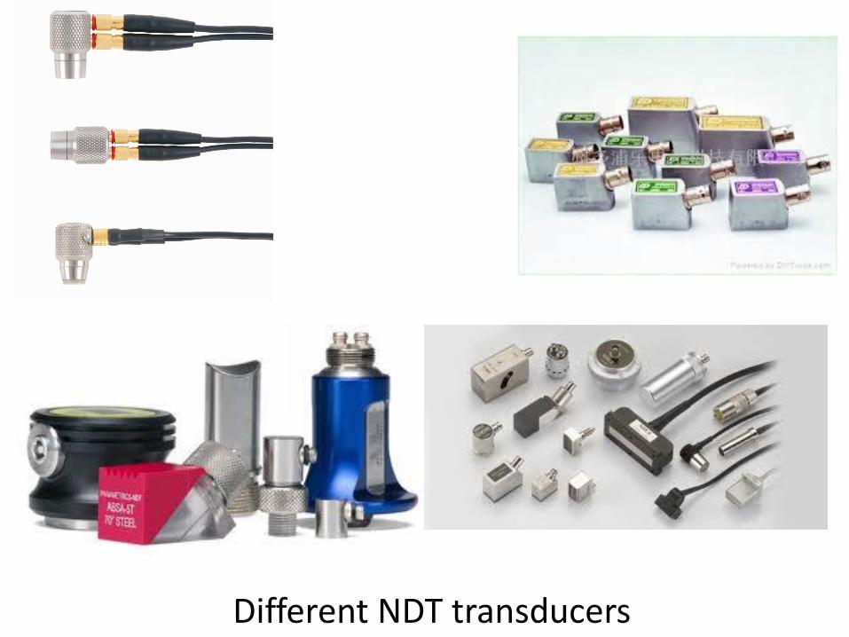
Different NDT transducers
As far back as the year 1880, the Curie brothers, Pierre and Jacques-Paul, discovered that when sectioned in specific planes certain crystal materials would generate a voltage when distorted. This is called “piezoelectricity”—electricity due to pressure. The opposite effect is also valid; i.e., if a voltage is applied to the crystal material, it will distort.
Lippman documented this about a year later. Quartz crystal is a prime example of this type of crystal. Other naturally occurring piezoelectric materials exist, such as tourmaline and Rochelle salt.
These crystals were used in the early days of ultrasonic testing until polycrystalline ceramic materials—materials that do not exhibit piezoelectric properties in their original state—were developed to perform this function.
Some of the more common polycrystalline materials used in transducers are lead zirconate titanate (PZT) and lead metaniobate (PMN). The material is mixed in the form of a slurry, poured into a mold, then dried under pressure. It is then sliced to the required thickness.
This is the thickness at which the element will resonates at its designed frequency. (Materials resonate according to their formulation and thickness. For example, a 5 MHz transducer element from PZT may be a different thickness than its counterpart made from PMN).
The slices are then placed on a lapping table and precision lapped to the final thickness. The next step is to coat the element with a very thin layer of conductive material, usually silver.
This is sometimes electrostatically applied. At this stage, the element is not yet active.
A second major step forward occurred in the 1940s with the development of poled ceramic transducers of the lead zirconate (PZT) family, which were relatively inexpensive, rugged, high performance, and ideally suited to field work. For the laboratory, more expensive but very high-performance new crystals such as lithium niobate entered into widespread use. A third wave occurred with piezoelectric films.
The development of polyvinylidine (PVDF) and then copolymers based on it was important for many niche applications—particularly in medical ultrasonics, as the acoustic impedance is very well matched to water..
More recently, the original PZT family has been improved by the use of finely engineered piezocomposites for general BAW applications. New SAW substrates are still under development, particularly with the push to higher frequencies.
Microelectromechanical (MEMS) transducers are under a stage of intense development as they have potential for high-quality, real-time, mass-produced acoustic imaging systems.
The transducer incorporates a piezoelectric element, which converts electrical signals into mechanical vibrations (transmit mode) and mechanical vibrations into electrical signals (receive mode).
Many factors, including material, mechanical and electrical construction, and the external mechanical and electrical load conditions, influence the behavior of a transducer. Mechanical construction includes parameters such as the radiation surface area, mechanical damping, housing, connector type and other variables of physical construction.

Mechanical construction includes parameters such as the radiation surface area, mechanical damping, housing, connector .
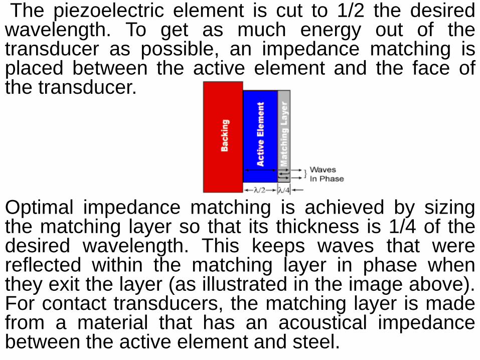
The piezoelectric element is cut to 1/2 the desired wavelength. To get as much energy out of the transducer as possible, an impedance matching is placed between the active element and the face of the transducer.
Optimal impedance matching is achieved by sizing the matching layer so that its thickness is 1/4 of the desired wavelength. This keeps waves that were reflected within the matching layer in phase when they exit the layer (as illustrated in the image above). For contact transducers, the matching layer is made from a material that has an acoustical impedance between the active element and steel.
The backing material supporting the crystal has a great influence on the damping characteristics of a transducer. The bond between the backing material and the element is of primary importance, as is the acoustic impedance match between the element and the backing material.
Using a backing material with an impedance similar to that of the active element will produce the most effective damping. Such a transducer will have a wider bandwidth resulting in higher sensitivity.
As the mismatch in impedance between the active element and the backing material increases, material penetration increases but transducer sensitivity is reduced.
It is also important to understand the concept of bandwidth, or range of frequencies, associated with a transducer.
The frequency noted on a transducer is the central or center
frequency and depends primarily on the backing material.
Highly damped transducers will respond to frequencies above and
below the central frequency. The broad frequency range provides
a transducer with high resolving power.
Less damped transducers will exhibit a narrower frequency range
and poorer resolving power, but greater penetration.
The central frequency will also define the capabilities of a
transducer.
Lower frequencies (0.5MHz-2.25MHz) provide greater energy and
penetration in a material, while high frequency crystals (15.0MHz-
25.0MHz) provide reduced penetration but greater sensitivity to
small discontinuities.
Different materials have different acoustic properties. In some a sound wave
can travel easily, in others it's absorbed which can make achieving an accurate
measurement difficult. Different frequencies of sound allow measurement of
different materials, so when selecting a transducer the material type and
therefore the frequency are the first consideration.
Low frequency ultrasonic transducers have the highest power and can
penetrate deeply into a material in the same way that the bass notes of music
from a car stereo can penetrate the body of a car and be heard outside. Low
frequency ultrasonic transducers are best materials that absorb sound like
plastics or composites. A low frequency transducer increases the chance of
getting a strong return echo and a good quality measurement on these
materials.
High frequency ultrasonic transducers are ideal for precision
measurement because the pulse they emit is highly focused, reducing the risk
of return echos outside of the measurement area. The high frequency and
shorter wavelength also lends itself well to measuring thin materials. A third
advantage is that high frequency ultrasonic transducers reduce troublesome
“surface noise” that can be present on some metals such as aluminium or
titanium and can cause measurement error.
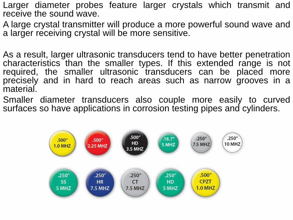
Larger diameter probes feature larger crystals which transmit and receive the sound wave.
A large crystal transmitter will produce a more powerful sound wave and a larger receiving crystal will be more sensitive.
As a result, larger ultrasonic transducers tend to have better penetration characteristics than the smaller types. If this extended range is not required, the smaller ultrasonic transducers can be placed more precisely and in hard to reach areas such as narrow grooves in a material.
Smaller diameter transducers also couple more easily to curved surfaces so have applications in corrosion testing pipes and cylinders.
Types of transducers
Transducers are classified into groups according to the
application.
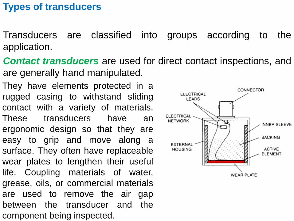
Contact transducers are used for direct contact inspections, and
are generally hand manipulated.
They have elements protected in a
rugged casing to withstand sliding
contact with a variety of materials.
These transducers have an
ergonomic design so that they are
easy to grip and move along a
surface. They often have replaceable
wear plates to lengthen their useful
life. Coupling materials of water,
grease, oils, or commercial materials
are used to remove the air gap
between the transducer and the
component being inspected.
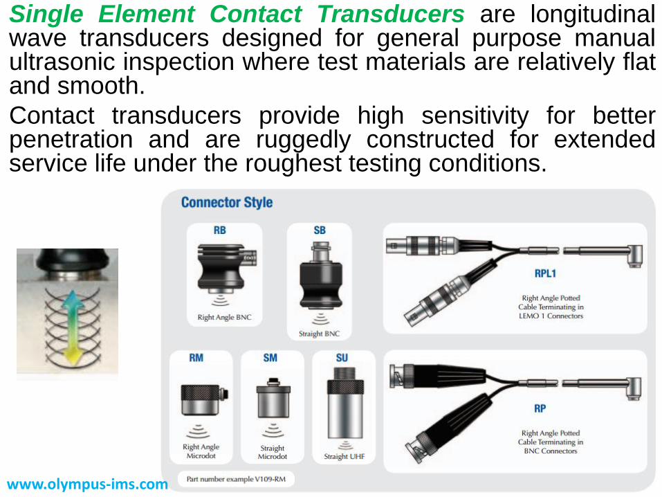
Single Element Contact Transducers are longitudinal wave transducers designed for general purpose manual ultrasonic inspection where test materials are relatively flat and smooth.
Contact transducers provide high sensitivity for better penetration and are ruggedly constructed for extended service life under the roughest testing conditions.
www.olympus-ims.com
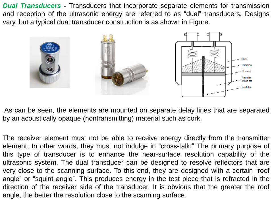
Dual Transducers - Transducers that incorporate separate elements for transmission
and reception of the ultrasonic energy are referred to as “dual” transducers. Designs
vary, but a typical dual transducer construction is as shown in Figure.
As can be seen, the elements are mounted on separate delay lines that are separated
by an acoustically opaque (nontransmitting) material such as cork.
The receiver element must not be able to receive energy directly from the transmitter
element. In other words, they must not indulge in “cross-talk.” The primary purpose of
this type of transducer is to enhance the near-surface resolution capability of the
ultrasonic system. The dual transducer can be designed to resolve reflectors that are
very close to the scanning surface. To this end, they are designed with a certain “roof
angle” or “squint angle”. This produces energy in the test piece that is refracted in the
direction of the receiver side of the transducer. It is obvious that the greater the roof
angle, the better the resolution close to the scanning surface.
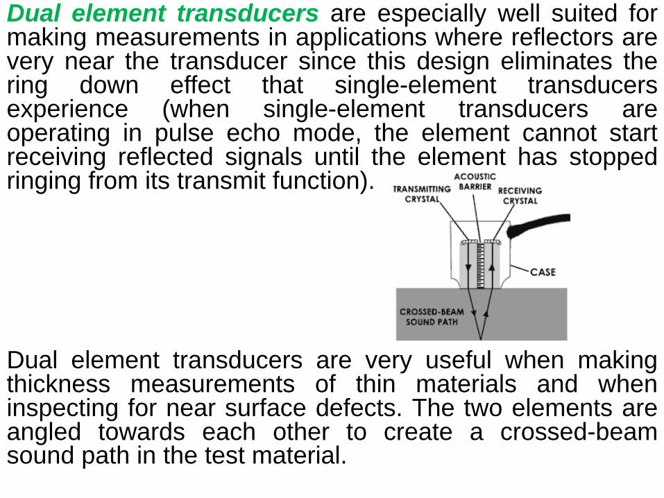
Dual element transducers are especially well suited for making measurements in applications where reflectors are very near the transducer since this design eliminates the ring down effect that single-element transducers experience (when single-element transducers are operating in pulse echo mode, the element cannot start receiving reflected signals until the element has stopped ringing from its transmit function).
Dual element transducers are very useful when making thickness measurements of thin materials and when inspecting for near surface defects. The two elements are angled towards each other to create a crossed-beam sound path in the test material.
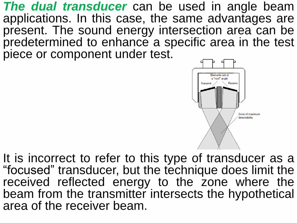
The dual transducer can be used in angle beam applications. In this case, the same advantages are present. The sound energy intersection area can be predetermined to enhance a specific area in the test piece or component under test.
It is incorrect to refer to this type of transducer as a “focused” transducer, but the technique does limit the received reflected energy to the zone where the beam from the transmitter intersects the hypothetical area of the receiver beam.

Angle beam transducers and wedges are typically used to introduce a refracted shear wave into the test material. Transducers can be purchased in a variety of fixed angles or in adjustable versions where the user determines the angles of incidence and refraction. In the fixed angle versions, the angle of refraction that is marked on the transducer is only accurate for a particular material, which is usually steel. The angled sound path allows the sound beam to be reflected from the backwall to improve detectability of flaws in and around welded areas. They are also used to generate surface waves for use in detecting defects on the surface of a component.
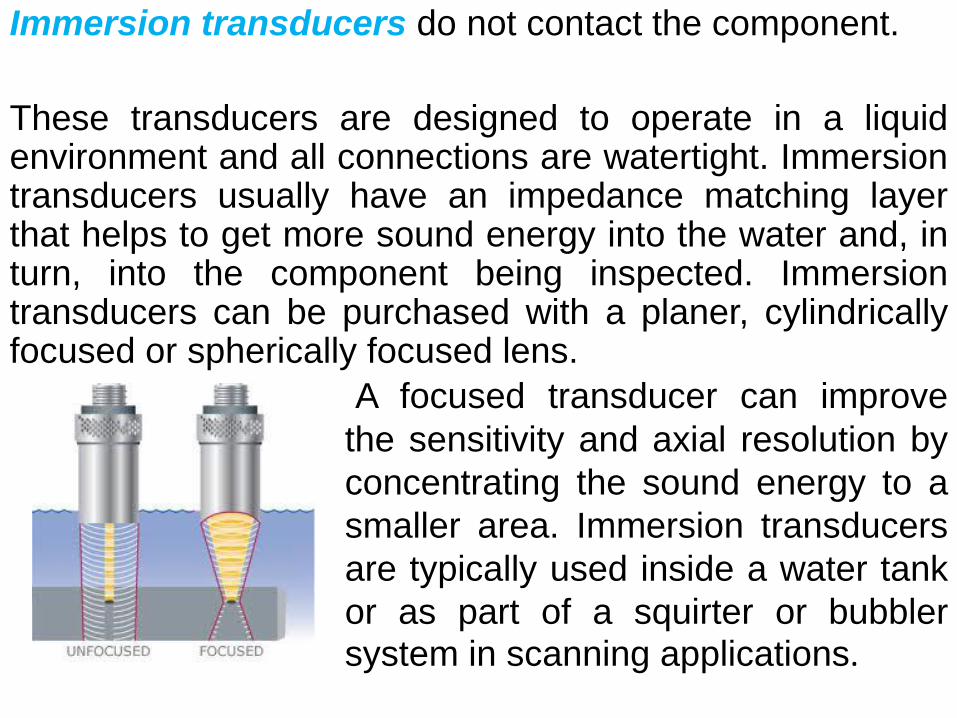
Immersion transducers do not contact the component.
These transducers are designed to operate in a liquid environment and all connections are watertight. Immersion transducers usually have an impedance matching layer that helps to get more sound energy into the water and, in turn, into the component being inspected. Immersion transducers can be purchased with a planer, cylindrically focused or spherically focused lens.
A focused transducer can improve
the sensitivity and axial resolution by
concentrating the sound energy to a
smaller area. Immersion transducers
are typically used inside a water tank
or as part of a squirter or bubbler system in scanning applications.

Single Element Immersion Transducers are longitudinal wave transducers typically used in manual, semi-automatic, and automatic scanning systems.
Scanning parts with irregular or complex geometries is possible because of the conforming “water path” layer between the probe and the inspected material.
Superior near-surface resolution can be achieved when compared to contact transducers. Angle beam inspection is possible by simply angling the probe or search tube in relation to the part surface. Focal length must be specified.
Spherical (point) or cylindrical (line)
focusing can also be accomplished using acoustically matched lenses.
Transducer Problems
As mentioned previously, the ultrasonic test begins with the transducer. It is therefore of all most importance that the transducer is performing as required.
Problems with the transducer need to be identified prior to any test. It is advisable to document the performance of each transducer when purchased so that its performance can be monitored during its lifetime. Items such as pulse width, amplitude, and angle (if appropriate) should be quantified.
Photographs of the spectrum and wave-form should be acquired. These parameters should be checked on a regular basis and the performance verified. It is advisable to verify the parameters on the same system each time it is used.
Variables such as pulsers, receivers, and cables, can exhibit anomalies that may be erroneously attributed to the transducer alone.
Possibilities of changes in performance include,
but are not limited to:
1. Pulse length. This can increase for the following
reasons:
a) The backing or damping material becomes detached from the
transducer.
b) The wear face becomes detached from the transducer.
c) The element or wear-face is cracked.
d) The tuning coil is detached.
2. Low sensitivity. This can occur for a number of
reasons such as, but not limited to: a) Deterioration of or damage to the transducer element material.
b) Detachment of the transducer face.
c) Detachment of the tuning coil.

3. Beam skew (apparent) due to partial
detachment of the transducer face.
4. Faulty connections. Damaged or loose wires in
the transducer housing.
5. In the case of angle beam transducers,
wearing down of the Plexiglas wedge may cause
the refracted angle to change.

Couplant
A couplant is a material (usually liquid) that facilitates the transmission of ultrasonic energy from the transducer into the test specimen. Couplant is generally necessary because the acoustic impedance mismatch between air and solids (i.e. such as the test specimen) is large. Therefore, nearly all of the energy is reflected and very little is transmitted into the test material. The couplant displaces the air and makes it possible to get more sound energy into the test specimen so that a usable ultrasonic signal can be obtained. In contact ultrasonic testing a thin film of oil, glycerin or water is generally used between the transducer and the test surface.
When scanning over the part or making precise measurements, an immersion technique is often used. In immersion ultrasonic testing both the transducer and the part are immersed in the couplant, which is typically water. This method of coupling makes it easier to maintain consistent coupling while moving and manipulating the transducer and/or the part.

TECHNIQUES
The ways in which sound waves propagate through materials and are attenuated, reflected, or transmitted dictate the different ultrasonic methods or techniques used to detect the many types of discontinuities that can exist in materials.
These techniques fall into two main categories, one called “pulse-echo,” and the other called “through-transmission.”
Any of the techniques that may be used requires calibration of the ultrasonic system so that the time base can have some meaning in terms of material thickness.
Calibration Techniques
The process of calibration needs to be just as disciplined as the inspection technique. In fact, the whole inspection relies on the calibration process. Some of the following calibration techniques are concerned with measuring and documenting the characteristics of the transducer and flaw detector.

The basic calibration blocks define by BS 2704 A.2 block, also known as the International Institute of Welding (IIW) block, is illustrated below. Also in USA, this block is known as the IIW Type A2 block and the dimensions are in inches.
The block can be used for the following assessments: Calibration of the time base in terms of thickness;
Checking linearity of the time base;
Assessing overall sensitivity of probe and amplifier;
Determination of the angle of refraction;
Determination of beam characteristics;
Checking linearity of the amplifier
Checking resolution;
Determination the probe index;
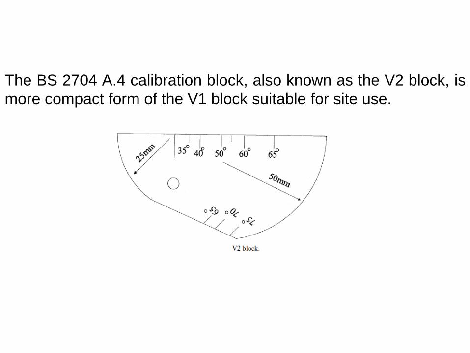
The BS 2704 A.4 calibration block, also known as the V2 block, is
more compact form of the V1 block suitable for site use.

7. Ultrasonic inspection
equipments and materials
1.Introduction in Nondestructive testing.
2.Discontinuities , origin and classification
3.Visual testing.
4.Liquid penetrant inspection method.
5.Process control and interpretation of liquid penetrant inspection
6.Ultrasonic inspection method
7.Ultrasonic inspection equipments and materials.
8.Ultrasonic inspections process control and safety.
9.Magnetic particle testing theory
10.Magnetic particle inspection applications and interpretations
11.Eddy current inspection method.
12.Application on eddy current inspection
13.Acoustic emission testing.
14.Thermal infrared testing.
Topic

8.Ultrasonic inspections
process control and safety.
Inspection Techniques
Pulse-Echo Techniques
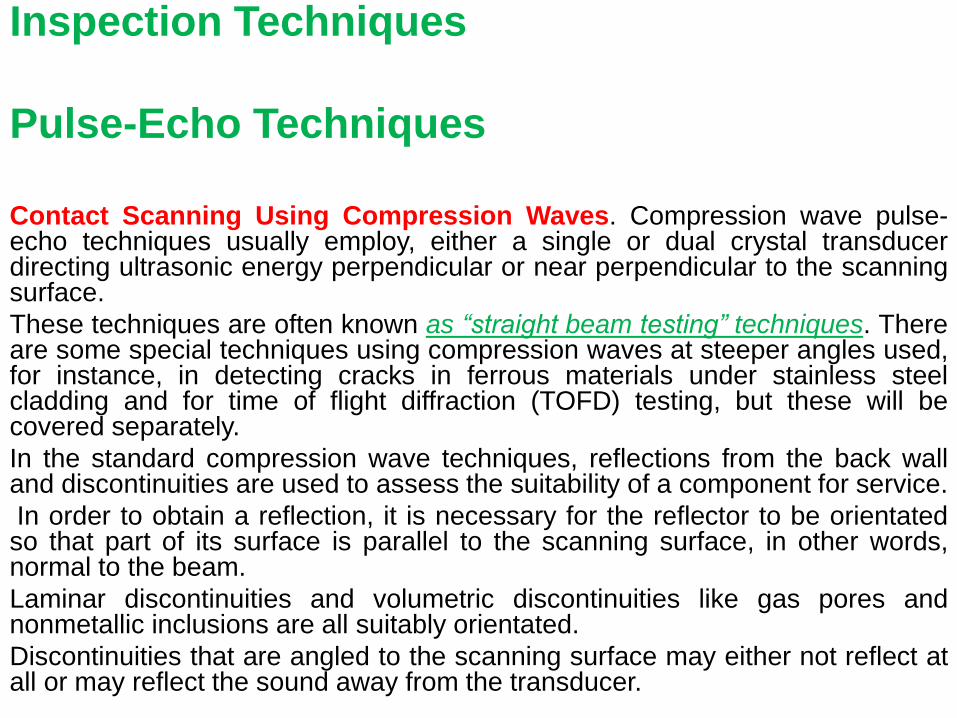
Contact Scanning Using Compression Waves. Compression wave pulse-echo techniques usually employ, either a single or dual crystal transducer directing ultrasonic energy perpendicular or near perpendicular to the scanning surface.
These techniques are often known as “straight beam testing” techniques. There are some special techniques using compression waves at steeper angles used, for instance, in detecting cracks in ferrous materials under stainless steel cladding and for time of flight diffraction (TOFD) testing, but these will be covered separately.
In the standard compression wave techniques, reflections from the back wall and discontinuities are used to assess the suitability of a component for service.
In order to obtain a reflection, it is necessary for the reflector to be orientated so that part of its surface is parallel to the scanning surface, in other words, normal to the beam.
Laminar discontinuities and volumetric discontinuities like gas pores and nonmetallic inclusions are all suitably orientated.
Discontinuities that are angled to the scanning surface may either not reflect at all or may reflect the sound away from the transducer.
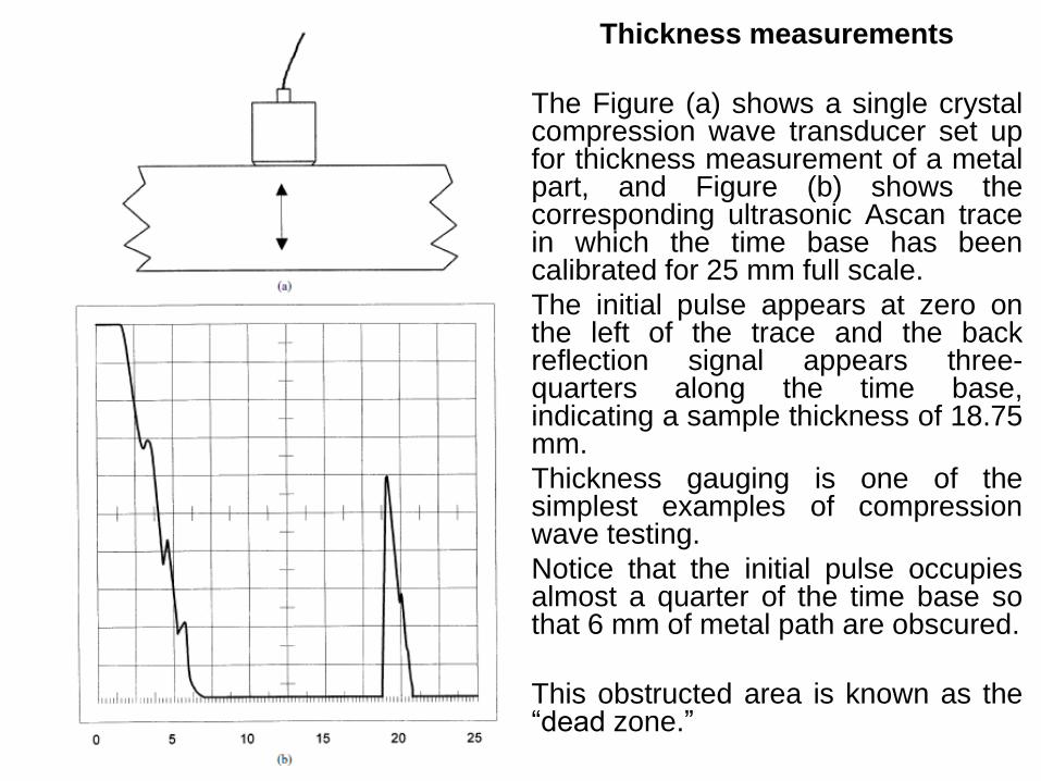
Thickness measurements
The Figure (a) shows a single crystal compression wave transducer set up for thickness measurement of a metal part, and Figure (b) shows the corresponding ultrasonic Ascan trace in which the time base has been calibrated for 25 mm full scale.
The initial pulse appears at zero on the left of the trace and the back reflection signal appears three-quarters along the time base, indicating a sample thickness of 18.75 mm.
Thickness gauging is one of the simplest examples of compression wave testing.
Notice that the initial pulse occupies almost a quarter of the time base so that 6 mm of metal path are obscured.
This obstructed area is known as the “dead zone.”
Another example of measurement
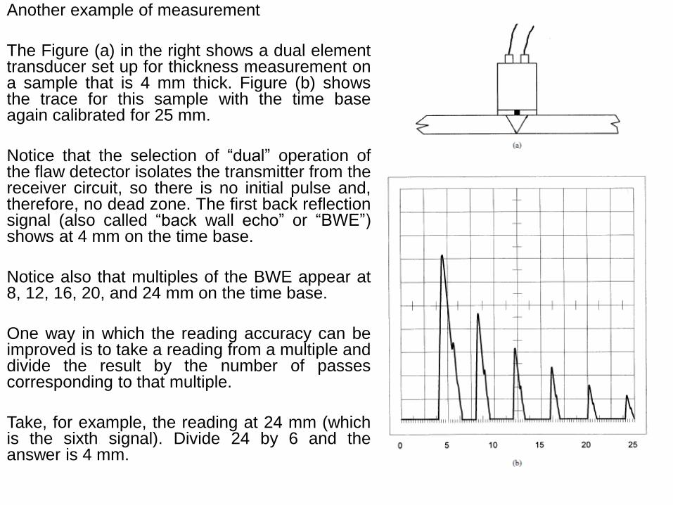
The Figure (a) in the right shows a dual element transducer set up for thickness measurement on a sample that is 4 mm thick. Figure (b) shows the trace for this sample with the time base again calibrated for 25 mm.
Notice that the selection of “dual” operation of the flaw detector isolates the transmitter from the receiver circuit, so there is no initial pulse and, therefore, no dead zone. The first back reflection signal (also called “back wall echo” or “BWE”) shows at 4 mm on the time base.
Notice also that multiples of the BWE appear at 8, 12, 16, 20, and 24 mm on the time base.
One way in which the reading accuracy can be improved is to take a reading from a multiple and divide the result by the number of passes corresponding to that multiple.
Take, for example, the reading at 24 mm (which is the sixth signal). Divide 24 by 6 and the answer is 4 mm.
Contact Scanning Using Angle Beam Shear Waves.
If the possible orientation of any discontinuity is considered to be unfavorable to a beam perpendicular to the scanning surface, it will be necessary to tilt the beam to an appropriate angle to ensure that the beam strikes the discontinuity as near perpendicular as possible.
For small angles (up to about 10° in the test material), compression waves may be used. However, for larger angles, mode conversion to shear wave energy makes the use of compression waves alone impossible.
It therefore becomes necessary to increase the incident angle beyond the first critical angle, leaving only a shear wave in the part.
The lowest practical angle for testing with a shear wave alone is about 35° refracted shear wave angle. This does not mean that testing at angles between 10° and 35° is impossible.
However, if an angle in this range needs to be used, the practitioner must consider carefully the geometry of the part. The next decision is whether to use the compression wave or the simultaneous shear wave, depending on what happens to the unwanted mode. Regular off the shelf transducers are either straight beam compression wave or shear wave angle transducers of 35° to 70°.
The common or “preferred” angles available in ultrasonics for shear wave testing are 45°, 60°, and 70°, although other angles can be made to order. The angles marked on a shear wave transducer are for steel, unless followed by an identifying letter for other materials.
For instance, “45°Al” would denote a 45° shear wave angle transducer for aluminum.
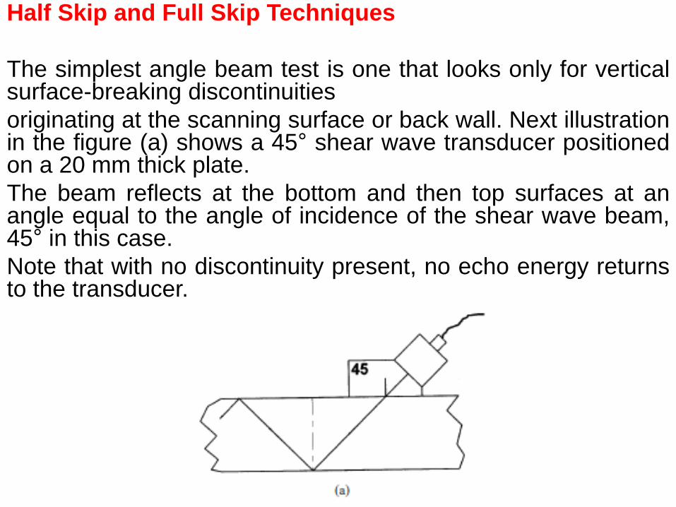
Half Skip and Full Skip Techniques
The simplest angle beam test is one that looks only for vertical surface-breaking discontinuities
originating at the scanning surface or back wall. Next illustration in the figure (a) shows a 45° shear wave transducer positioned on a 20 mm thick plate.
The beam reflects at the bottom and then top surfaces at an angle equal to the angle of incidence of the shear wave beam, 45° in this case.
Note that with no discontinuity present, no echo energy returns to the transducer.
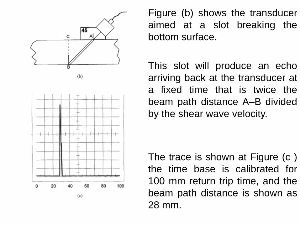
Figure (b) shows the transducer
aimed at a slot breaking the
bottom surface.
This slot will produce an echo
arriving back at the transducer at
a fixed time that is twice the
beam path distance A–B divided
by the shear wave velocity.
The trace is shown at Figure (c )
the time base is calibrated for
100 mm return trip time, and the
beam path distance is shown as
28 mm.
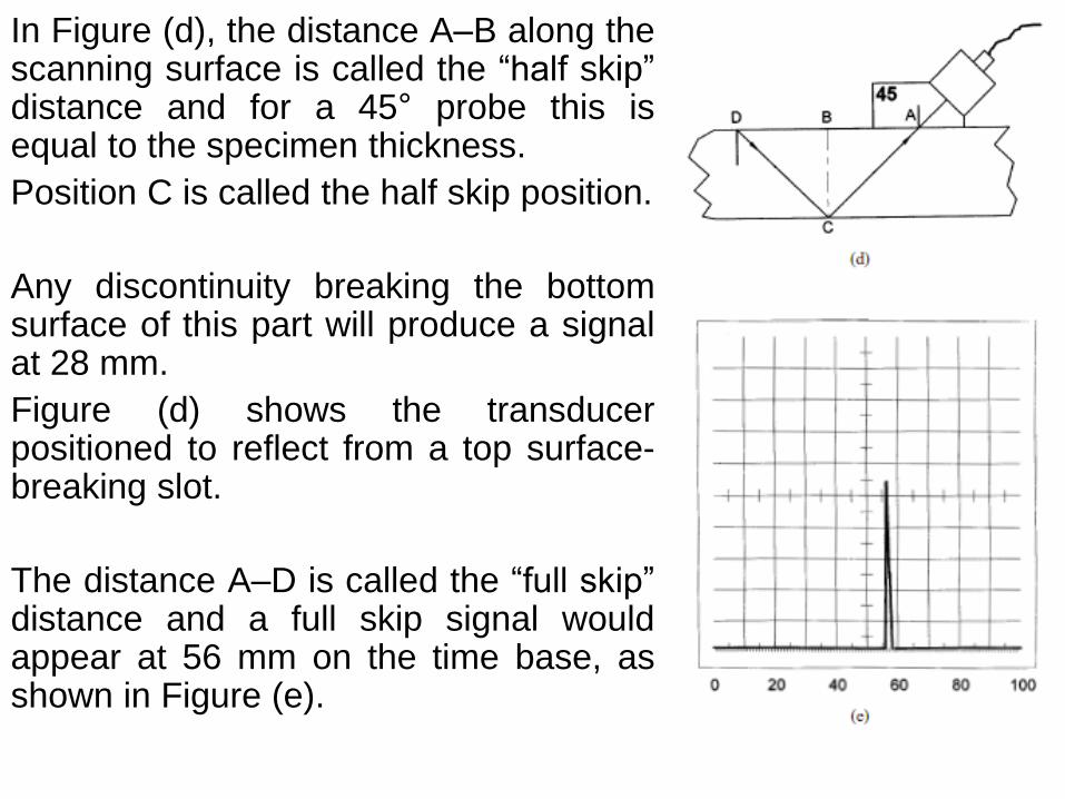
In Figure (d), the distance A–B along the scanning surface is called the “half skip” distance and for a 45° probe this is equal to the specimen thickness.
Position C is called the half skip position.
Any discontinuity breaking the bottom surface of this part will produce a signal at 28 mm.
Figure (d) shows the transducer positioned to reflect from a top surface-breaking slot.
The distance A–D is called the “full skip” distance and a full skip signal would appear at 56 mm on the time base, as shown in Figure (e).
If the transducer is scanned along a 20 mm plate containing top and bottom surface-breaking discontinuities, only three signal patterns are possible:
1. No signal representing sound material
2. A signal at 28 mm representing a bottom corner reflector
3. A signal at 56 mm representing a top corner reflector
For the practitioner, interpretation of results is relatively simple since there are only two screen locations on which to concentrate.
The technique is commonly used to detect fatigue cracks during the in-service inspection of critical components.

Beam Path Distance Techniques
Of course, not all discontinuities occur at the top or bottom surfaces.
In welds or castings, for example, planar and volumetric discontinuities may occur anywhere within the volume of the part.
In order to detect, correctly assess, and position such discontinuities, it is necessary to determine the distance along the beam path at which the reflection occurs.
This distance together with the known beam direction and angle allows the position of the discontinuity to be plotted.
Volumetric discontinuities, such as gas pores or slag inclusions in welds, are not very sensitive to beam angle.
Approached from almost any direction, there is likely to be a facet of the discontinuity that will reflect back to the transducer.
On the other hand, planar discontinuities, such as lack of side wall fusion in welds and angular cracks, are very sensitive to beam angle.
The practitioner must be aware of the types of discontinuities that might occur during fabrication and service in a part to be inspected.
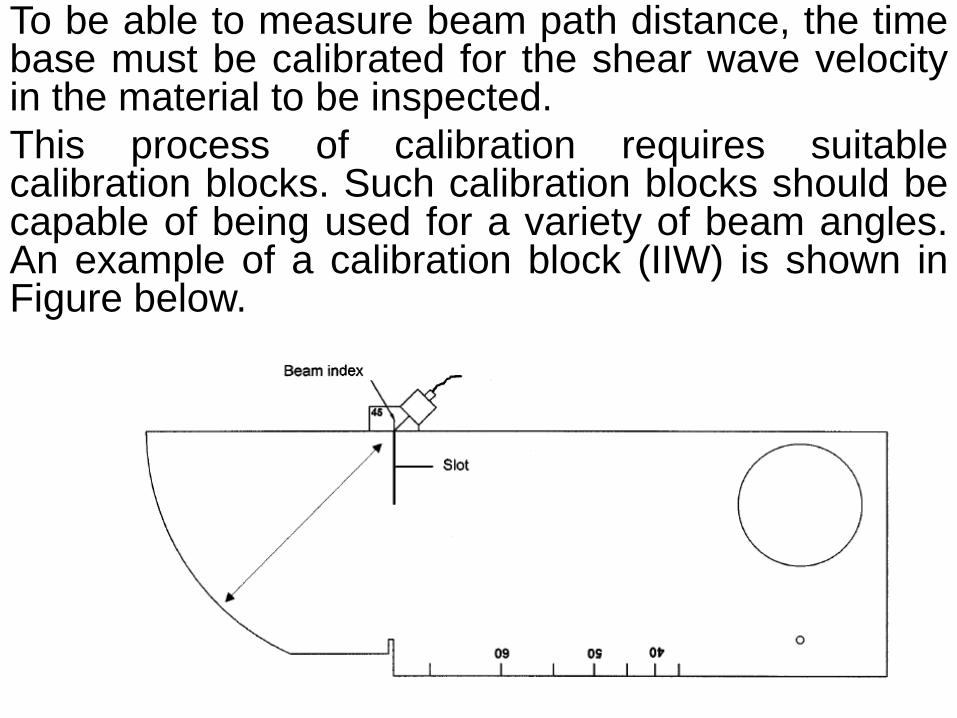
To be able to measure beam path distance, the time base must be calibrated for the shear wave velocity in the material to be inspected.
This process of calibration requires suitable calibration blocks. Such calibration blocks should be capable of being used for a variety of beam angles. An example of a calibration block (IIW) is shown in Figure below.

8.Ultrasonic inspections process control and safety.
END of PART - I -