nj/nx/ny-series controller startup guide for simulink ... · pdf filenj/nx/ny-series...
TRANSCRIPT
NJ/NX/NY-series Control ler
Startup Guide for Simulink® & Sysmac Studio
SYSMAC-SE20□□
NX701-□□□□
NX1P2-□□□□
NJ501-□□□□
NJ301-□□□□
NJ101-□□□□
NY532-□□□□
NY512-□□□□
R88D-KN□-ECT
R88D-1SN□-ECT
GX-AD0471/DA0271
NX-AD□□□□
NX-DA□□□□
NA5-□W□□□□ NA5-□□W□□□□
W529-E1-05

©OMRON, 2013 - 2017 All rights reserved. No part of this publication may be reproduced, stored in a retrieval system, or transmitted, in any
form, or by any means, mechanical, electronic, photocopying, recording, or otherwise, without the prior written
permission of OMRON.
No patent liability is assumed with respect to the use of the information contained herein. Moreover, because
OMRON is constantly striving to improve its high-quality products, the information contained in this manual is
subject to change without notice. Every precaution has been taken in the preparation of this manual. Nevertheless,
OMRON assumes no responsibility for errors or omissions. Neither is any liability assumed for damages resulting
from the use of the information contained in this publication.
1
Introduction
The NJ/NX/NY-series Controller Startup Guide for Simulink® and Sysmac Studio (hereinafter, may be referred to as “this Guide”) describes the startup procedures that are required to use a combination of Simulink® from The MathWorks® Inc. and the NJ/NX/NY-series Controller for the first time and the basic operating instructions for the Sysmac Studio. A simple single-axis positioning example is used for the discussion. You can perform the procedures that are presented in this Guide to quickly gain a basic understanding of the combination of Simulink® and the NJ/NX/NY-series Controller. This Guide does not contain safety information and other details that are required for actual use. Thoroughly read and understand the manuals for all of the devices that are used in this Guide to ensure that the system is used safely. Review the entire contents of these materials, including all safety precautions, precautions for safe use, and precautions for correct use.
Intended Audience This guide is intended for the following personnel. • Personnel in charge of introducing FA systems • Personnel in charge of designing FA systems The personnel must also have the following knowledge. • Knowledge of electrical systems (an electrical engineer or the equivalent) • Knowledge of MATLAB®/Simulink® from The MathWorks® Inc. • Knowledge of the NJ/NX/NY-series Controller • Knowledge of operation procedure of Sysmac Studio
Applicable Products
This guide covers the following products. • CPU Units of NJ/NX-series Machine Automation Controllers • Industrial PC Platform NY-series IPC Machine Controller • Sysmac Studio Automation Software • MATLAB®/Simulink® from The MathWorks® Inc. • Simulink® PLC Coder™ from The MathWorks® Inc.
Special Information The icons that are used in this Guide are described below.
Additional Information Additional information to read as required. This information is provided to increase understanding or make operation easier.
Precautions for Correct Use
Precautions on what to do and what not to do to ensure proper operation and performance.
2
Terms and Conditions Agreement NJ/NX/NY-series Controller
Warranties (a) Exclusive Warranty. Omron’s exclusive warranty is that the Products will be free from defects in materials and workmanship for a period of twelve months from the date of sale by Omron (or such other period expressed in writing by Omron). Omron disclaims all other warranties, express or implied. (b) Limitations. OMRON MAKES NO WARRANTY OR REPRESENTATION, EXPRESS OR IMPLIED, ABOUT NON-INFRINGEMENT, MERCHANTABILITY OR FITNESS FOR A PARTICULAR PURPOSE OF THE PRODUCTS. BUYER ACKNOWLEDGES THAT IT ALONE HAS DETERMINED THAT THE PRODUCTS WILL SUITABLY MEET THE REQUIREMENTS OF THEIR INTENDED USE. Omron further disclaims all warranties and responsibility of any type for claims or expenses based on infringement by the Products or otherwise of any intellectual property right. (c) Buyer Remedy. Omron’s sole obligation hereunder shall be, at Omron’s election, to (i) replace (in the form originally shipped with Buyer responsible for labor charges for removal or replacement thereof) the non-complying Product, (ii) repair the non-complying Product, or (iii) repay or credit Buyer an amount equal to the purchase price of the non-complying Product; provided that in no event shall Omron be responsible for warranty, repair, indemnity or any other claims or expenses regarding the Products unless Omron’s analysis confirms that the Products were properly handled, stored, installed and maintained and not subject to contamination, abuse, misuse or inappropriate modification. Return of any Products by Buyer must be approved in writing by Omron before shipment. Omron Companies shall not be liable for the suitability or unsuitability or the results from the use of Products in combination with any electrical or electronic components, circuits, system assemblies or any other materials or substances or environments. Any advice, recommendations or information given orally or in writing, are not to be construed as an amendment or addition to the above warranty. See http://www.omron.com/global/ or contact your Omron representative for published information. Limitation on Liability; Etc OMRON COMPANIES SHALL NOT BE LIABLE FOR SPECIAL, INDIRECT, INCIDENTAL, OR CONSEQUENTIAL DAMAGES, LOSS OF PROFITS OR PRODUCTION OR COMMERCIAL LOSS IN ANY WAY CONNECTED WITH THE PRODUCTS, WHETHER SUCH CLAIM IS BASED IN CONTRACT, WARRANTY, NEGLIGENCE OR STRICT LIABILITY. Further, in no event shall liability of Omron Companies exceed the individual price of the Product on which liability is asserted. Suitability of Use Omron Companies shall not be responsible for conformity with any standards, codes or regulations which apply to the combination of the Product in the Buyer’s application or use of the Product. At Buyer’s request, Omron will provide applicable third party certification documents identifying ratings and limitations of use which apply to the Product. This information by itself is not sufficient for a
3
complete determination of the suitability of the Product in combination with the end product, machine, system, or other application or use. Buyer shall be solely responsible for determining appropriateness of the particular Product with respect to Buyer’s application, product or system. Buyer shall take application responsibility in all cases. NEVER USE THE PRODUCT FOR AN APPLICATION INVOLVING SERIOUS RISK TO LIFE OR PROPERTY WITHOUT ENSURING THAT THE SYSTEM AS A WHOLE HAS BEEN DESIGNED TO ADDRESS THE RISKS, AND THAT THE OMRON PRODUCT(S) IS PROPERLY RATED AND INSTALLED FOR THE INTENDED USE WITHIN THE OVERALL EQUIPMENT OR SYSTEM. Programmable Products Omron Companies shall not be responsible for the user’s programming of a programmable Product, or any consequence thereof. Performance Data Data presented in Omron Company websites, catalogs and other materials is provided as a guide for the user in determining suitability and does not constitute a warranty. It may represent the result of Omron’s test conditions, and the user must correlate it to actual application requirements. Actual performance is subject to the Omron’s Warranty and Limitations of Liability. Change in Specifications Product specifications and accessories may be changed at any time based on improvements and other reasons. It is our practice to change part numbers when published ratings or features are changed, or when significant construction changes are made. However, some specifications of the Product may be changed without any notice. When in doubt, special part numbers may be assigned to fix or establish key specifications for your application. Please consult with your Omron’s representative at any time to confirm actual specifications of purchased Product. Errors and Omissions Information presented by Omron Companies has been checked and is believed to be accurate; however, no responsibility is assumed for clerical, typographical or proofreading errors or omissions.
4
Sysmac Studio Automation Software
1. WARRANTY (1) The warranty period for the Software is one year from the date of purchase, unless otherwise specifically agreed. (2) If the User discovers defect of the Software (substantial non-conformity with the manual), and return it to OMRON within the above warranty period, OMRON will replace the Software without charge by offering media or download from OMRON’s website. And if the User discovers defect of media which is attributable to OMRON and return it to OMRON within the above warranty period, OMRON will replace defective media without charge. If OMRON is unable to replace defective media or correct the Software, the liability of OMRON and the User’s remedy shall be limited to the refund of the license fee paid to OMRON for the Software. 2. LIMITATION OF LIABILITY (1) THE ABOVE WARRANTY SHALL CONSTITUTE THE USER’S SOLE AND EXCLUSIVE REMEDIES AGAINST OMRON AND THERE ARE NO OTHER WARRANTIES, EXPRESSED OR IMPLIED, INCLUDING BUT NOT LIMITED TO, WARRANTY OF MERCHANTABILITY OR FITNESS FOR PARTICULAR PURPOSE. IN NO EVENT, OMRON WILL BE LIABLE FOR ANY LOST PROFITS OR OTHER INDIRECT, INCIDENTAL, SPECIAL OR CONSEQUENTIAL DAMAGES ARISING OUT OF USE OF THE SOFTWARE. (2)OMRON SHALL HAVE NO LIABILITY FOR DEFECT OF THE SOFTWARE BASED ON MODIFICATION OR ALTERNATION TO THE SOFTWARE BY THE USER OR ANY THIRD PARTY. (3)OMRON SHALL HAVE NO LIABILITY FOR SOFTWARE DEVELOPED BY THE USER OR ANY THIRD PARTY BASED ON THE SOFTWARE OR ANY CONSEQUENCE THEREOF. 3. APPLICABLE CONDITIONS USER SHALL NOT USE THE SOFTWARE FOR THE PURPOSE THAT IS NOT PROVIDED IN THE ATTACHED USER MANUAL. 4. CHANGE IN SPECIFICATION The software specifications and accessories may be changed at any time based on improvements and other reasons. 5. EXTENT OF SERVICE The license fee of the Software does not include service costs, such as dispatching technical staff. 6. ERRORS AND OMISSIONS The information in this manual has been carefully checked and is believed to be accurate; however, no responsibility is assumed for clerical, typographical, or proofreading errors, or omissions.

5
Precautions • When building a system, check the specifications for all devices and equipment that will make
up the system and make sure that the OMRON products are used well within their rated specifications and performances. Safety measures, such as safety circuits, must be implemented in order to minimize the risks in the event of a malfunction.
• Thoroughly read and understand the manuals for all devices and equipment that will make up the system to ensure that the system is used safely. Review the entire contents of these manuals, including all safety precautions, precautions for safe use, and precautions for correct use.
• Confirm all regulations, standards, and restrictions that the system must adhere to. • Contact The MathWorks® Inc. for the codes that were outputted from Simulink® PLC Coder™. • Applicability of codes that were outputted from Simulink® PLC Coder™ must be judged by the
customer. • Check the user program for proper execution before you use it for actual operation.
Trademarks
• Sysmac and SYSMAC are trademarks or registered trademarks of OMRON Corporation in Japan and other countries for OMRON factory automation products.
• EtherCAT® is registered trademark and patented technology, licensed by Beckhoff Automation GmbH, Germany.
• MATLAB® and Simulink® are registered trademarks of The MathWorks® Inc. • Microsoft product screen shot(s) reprinted with permission from Microsoft Corporation.
Other company names and product names in this Guide are the trademarks or registered trademarks of their respective companies.
Software Licenses and Copyrights
The NJ/NX/NY-series Controller and the Sysmac Studio incorporate certain third party software. The license and copyright information associated with this software is available at http://www.fa.omron.co.jp/nj_info_e/.
6
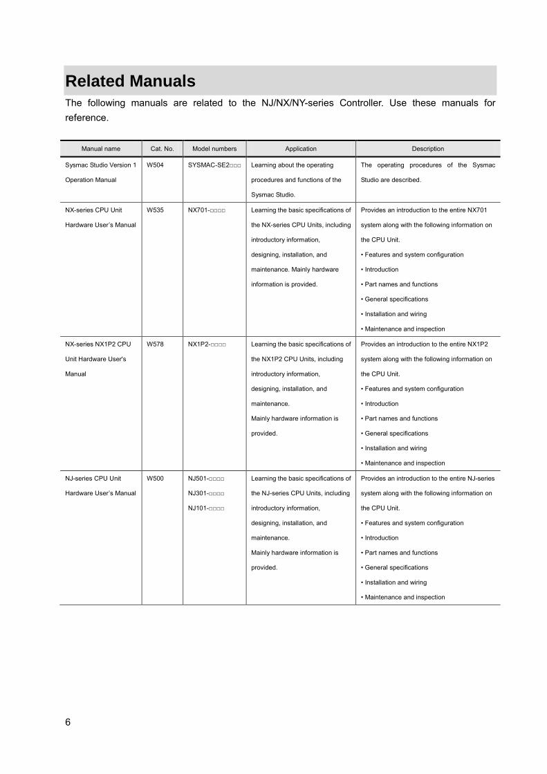
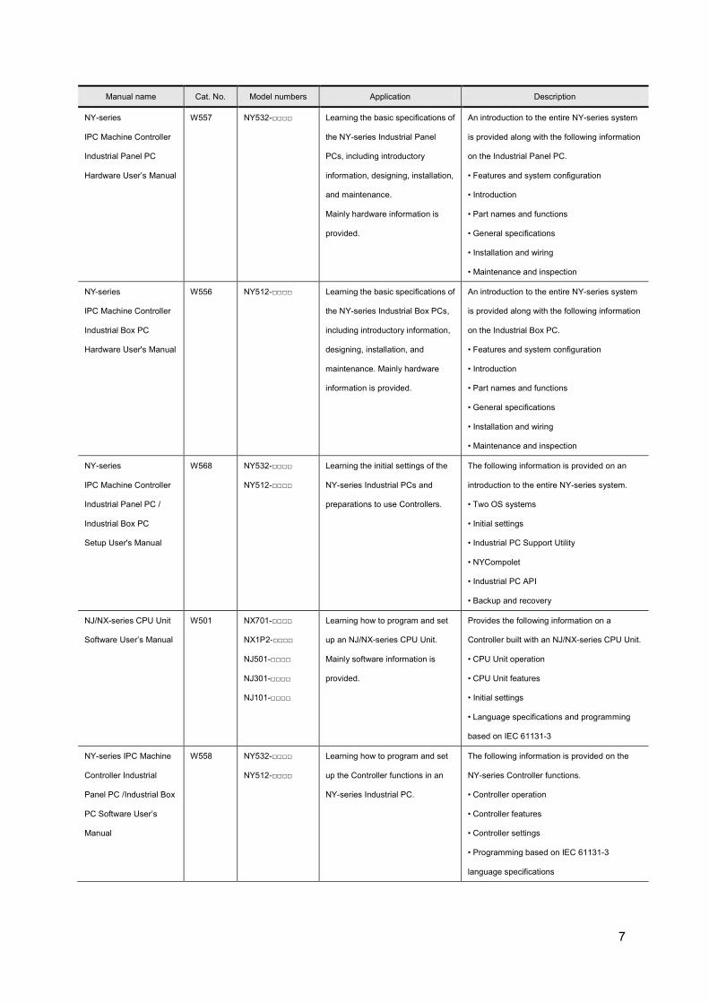
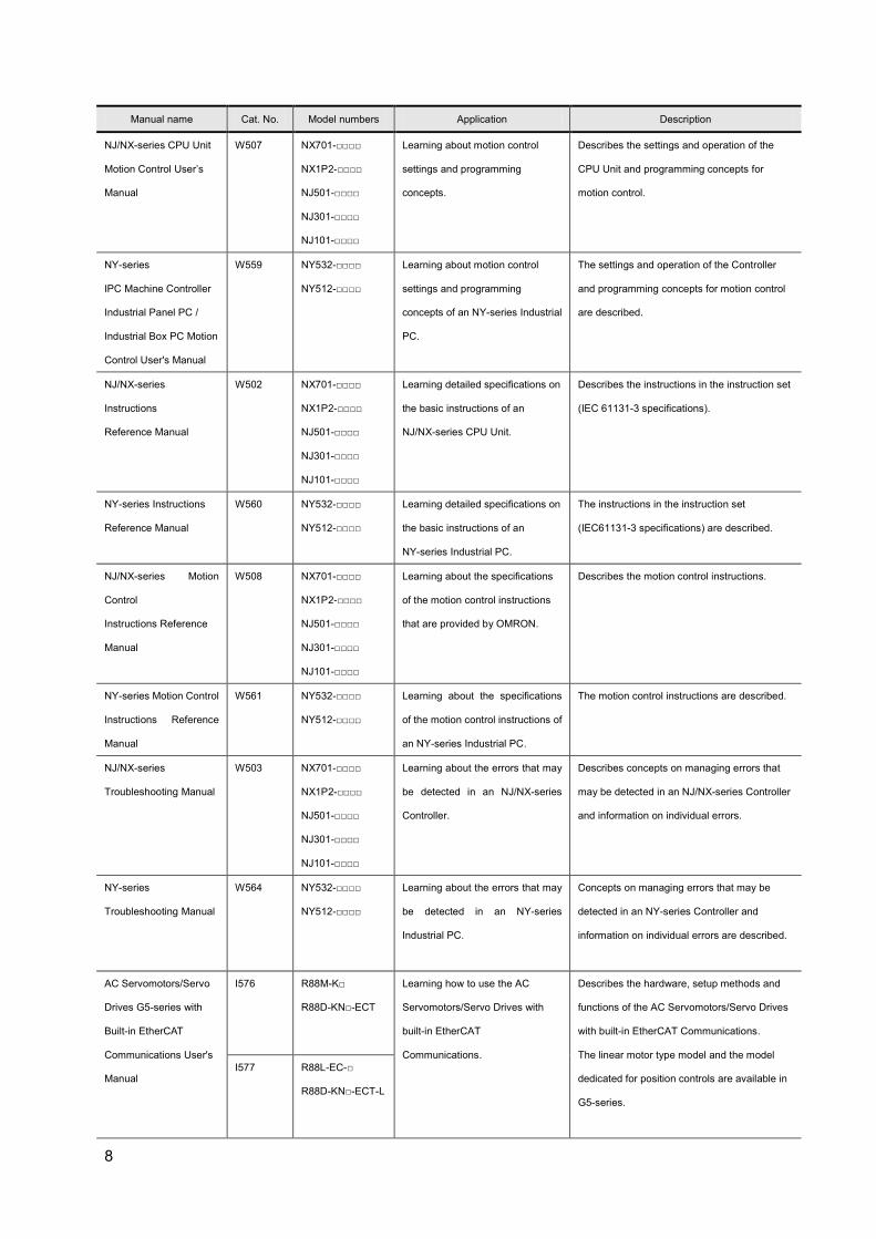
Related Manuals The following manuals are related to the NJ/NX/NY-series Controller. Use these manuals for reference.
Manual name Cat. No. Model numbers Application Description
Sysmac Studio Version 1
Operation Manual
W504 SYSMAC-SE2□□□ Learning about the operating
procedures and functions of the
Sysmac Studio.
The operating procedures of the Sysmac
Studio are described.
NX-series CPU Unit
Hardware User’s Manual
W535 NX701-□□□□ Learning the basic specifications of
the NX-series CPU Units, including
introductory information,
designing, installation, and
maintenance. Mainly hardware
information is provided.
Provides an introduction to the entire NX701
system along with the following information on
the CPU Unit.
• Features and system configuration
• Introduction
• Part names and functions
• General specifications
• Installation and wiring
• Maintenance and inspection
NX-series NX1P2 CPU
Unit Hardware User's
Manual
W578 NX1P2-□□□□ Learning the basic specifications of
the NX1P2 CPU Units, including
introductory information,
designing, installation, and
maintenance.
Mainly hardware information is
provided.
Provides an introduction to the entire NX1P2
system along with the following information on
the CPU Unit.
• Features and system configuration
• Introduction
• Part names and functions
• General specifications
• Installation and wiring
• Maintenance and inspection
NJ-series CPU Unit
Hardware User’s Manual
W500 NJ501-□□□□
NJ301-□□□□
NJ101-□□□□
Learning the basic specifications of
the NJ-series CPU Units, including
introductory information,
designing, installation, and
maintenance.
Mainly hardware information is
provided.
Provides an introduction to the entire NJ-series
system along with the following information on
the CPU Unit.
• Features and system configuration
• Introduction
• Part names and functions
• General specifications
• Installation and wiring
• Maintenance and inspection
7
Manual name Cat. No. Model numbers Application Description
NY-series
IPC Machine Controller
Industrial Panel PC
Hardware User’s Manual
W557 NY532-□□□□ Learning the basic specifications of
the NY-series Industrial Panel
PCs, including introductory
information, designing, installation,
and maintenance.
Mainly hardware information is
provided.
An introduction to the entire NY-series system
is provided along with the following information
on the Industrial Panel PC.
• Features and system configuration
• Introduction
• Part names and functions
• General specifications
• Installation and wiring
• Maintenance and inspection
NY-series
IPC Machine Controller
Industrial Box PC
Hardware User's Manual
W556 NY512-□□□□ Learning the basic specifications of
the NY-series Industrial Box PCs,
including introductory information,
designing, installation, and
maintenance. Mainly hardware
information is provided.
An introduction to the entire NY-series system
is provided along with the following information
on the Industrial Box PC.
• Features and system configuration
• Introduction
• Part names and functions
• General specifications
• Installation and wiring
• Maintenance and inspection
NY-series
IPC Machine Controller
Industrial Panel PC /
Industrial Box PC
Setup User's Manual
W568 NY532-□□□□
NY512-□□□□
Learning the initial settings of the
NY-series Industrial PCs and
preparations to use Controllers.
The following information is provided on an
introduction to the entire NY-series system.
• Two OS systems
• Initial settings
• Industrial PC Support Utility
• NYCompolet
• Industrial PC API
• Backup and recovery
NJ/NX-series CPU Unit
Software User’s Manual
W501 NX701-□□□□
NX1P2-□□□□
NJ501-□□□□
NJ301-□□□□
NJ101-□□□□
Learning how to program and set
up an NJ/NX-series CPU Unit.
Mainly software information is
provided.
Provides the following information on a
Controller built with an NJ/NX-series CPU Unit.
• CPU Unit operation
• CPU Unit features
• Initial settings
• Language specifications and programming
based on IEC 61131-3
NY-series IPC Machine
Controller Industrial
Panel PC /Industrial Box
PC Software User’s
Manual
W558 NY532-□□□□
NY512-□□□□
Learning how to program and set
up the Controller functions in an
NY-series Industrial PC.
The following information is provided on the
NY-series Controller functions.
• Controller operation
• Controller features
• Controller settings
• Programming based on IEC 61131-3
language specifications
8
Manual name Cat. No. Model numbers Application Description
NJ/NX-series CPU Unit
Motion Control User’s
Manual
W507 NX701-□□□□
NX1P2-□□□□
NJ501-□□□□
NJ301-□□□□
NJ101-□□□□
Learning about motion control
settings and programming
concepts.
Describes the settings and operation of the
CPU Unit and programming concepts for
motion control.
NY-series
IPC Machine Controller
Industrial Panel PC /
Industrial Box PC Motion
Control User's Manual
W559 NY532-□□□□
NY512-□□□□
Learning about motion control
settings and programming
concepts of an NY-series Industrial
PC.
The settings and operation of the Controller
and programming concepts for motion control
are described.
NJ/NX-series
Instructions
Reference Manual
W502 NX701-□□□□
NX1P2-□□□□
NJ501-□□□□
NJ301-□□□□
NJ101-□□□□
Learning detailed specifications on
the basic instructions of an
NJ/NX-series CPU Unit.
Describes the instructions in the instruction set
(IEC 61131-3 specifications).
NY-series Instructions
Reference Manual
W560 NY532-□□□□
NY512-□□□□
Learning detailed specifications on
the basic instructions of an
NY-series Industrial PC.
The instructions in the instruction set
(IEC61131-3 specifications) are described.
NJ/NX-series Motion
Control
Instructions Reference
Manual
W508 NX701-□□□□
NX1P2-□□□□
NJ501-□□□□
NJ301-□□□□
NJ101-□□□□
Learning about the specifications
of the motion control instructions
that are provided by OMRON.
Describes the motion control instructions.
NY-series Motion Control
Instructions Reference
Manual
W561 NY532-□□□□
NY512-□□□□
Learning about the specifications
of the motion control instructions of
an NY-series Industrial PC.
The motion control instructions are described.
NJ/NX-series
Troubleshooting Manual
W503 NX701-□□□□
NX1P2-□□□□
NJ501-□□□□
NJ301-□□□□
NJ101-□□□□
Learning about the errors that may
be detected in an NJ/NX-series
Controller.
Describes concepts on managing errors that
may be detected in an NJ/NX-series Controller
and information on individual errors.
NY-series
Troubleshooting Manual
W564 NY532-□□□□
NY512-□□□□
Learning about the errors that may
be detected in an NY-series
Industrial PC.
Concepts on managing errors that may be
detected in an NY-series Controller and
information on individual errors are described.
AC Servomotors/Servo
Drives G5-series with
Built-in EtherCAT
Communications User's
Manual
I576 R88M-K□
R88D-KN□-ECT
Learning how to use the AC
Servomotors/Servo Drives with
built-in EtherCAT
Communications.
Describes the hardware, setup methods and
functions of the AC Servomotors/Servo Drives
with built-in EtherCAT Communications.
The linear motor type model and the model
dedicated for position controls are available in
G5-series.
I577 R88L-EC-□
R88D-KN□-ECT-L

9
Manual name Cat. No. Model numbers Application Description
AC Servomotors/Servo
Drives 1S-series with
Built-in EtherCAT
Communications User’s
Manual
I586 R88M-1□
R88D-1SN□-ECT
Learning how to use the AC
Servomotors/Servo Drives with
built-in EtherCAT
Communications.
Describes the hardware, setup methods and
functions of the AC Servomotors/Servo Drives
with built-in EtherCAT Communications.
GX-series EtherCAT
Slave Units User’s
Manual
W488 GX-ID□□□□
GX-OD□□□□
GX-OC□□□□
GX-MD□□□□
GX-AD□□□□
GX-DA□□□□
GX-EC□□□□
XWT-ID□□
XWT-OD□□
Learning how to use the EtherCAT
remote I/O terminals.
Describes the hardware, setup methods and
functions of the EtherCAT remote I/O terminals.
NX-series EtherCAT
Coupler Unit User’s
Manual
W519 NX-ECC□□□ Leaning how to use an NX-series
EtherCAT Coupler Unit and
EtherCAT Slave Terminals
The system and configuration of EtherCAT
Slave Terminals, which consist of an NX-series
EtherCAT Coupler Unit and NX Units, are
described along with the hardware, setup, and
functions of the EtherCAT Coupler Unit that are
required to configure, control, and monitor NX
Units through EtherCAT.
NX-series NX Units
User’s Manual
W522 NX-AD□□□□
NX-DA□□□□
Learning how to use NX Units Describes the hardware, setup methods, and
functions of the NX Units.
Manuals are available for the following Units.
Digital I/O Units, Analog I/O Units, System
Units, Position Interface Units,
Communications Interface Units, Load Cell
Input Units, and IOLink Master Units.
NA-series
Programmable
Terminal Hardware
User’s Manual
V117 NA5-□W□□□□
NA5-□□W□□□□
Learning the specifications and
settings required to install an
NA-series PT and connect
peripheral devices.
Information is provided on NA-series PT
specifications, part names, installation
procedures, and procedures to connect an NA
Unit to peripheral devices.
Information is also provided on maintenance
after operation and troubleshooting.
NA-series
Programmable
Terminal Software
User’s Manual
V118 NA5-□W□□□□
NA5-□□W□□□□
Learning about NA-series PT
pages and object functions.
NA-series PT pages and object functions are
described.
10
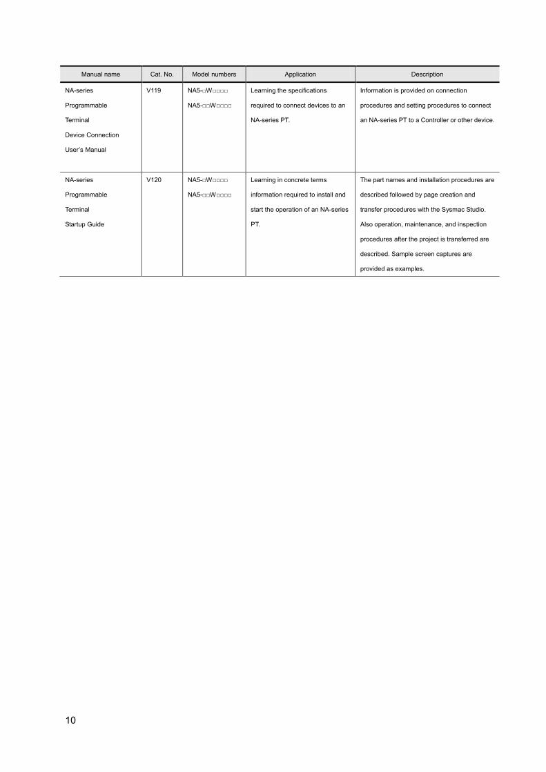
Manual name Cat. No. Model numbers Application Description
NA-series
Programmable
Terminal
Device Connection
User’s Manual
V119 NA5-□W□□□□
NA5-□□W□□□□
Learning the specifications
required to connect devices to an
NA-series PT.
Information is provided on connection
procedures and setting procedures to connect
an NA-series PT to a Controller or other device.
NA-series
Programmable
Terminal
Startup Guide
V120 NA5-□W□□□□
NA5-□□W□□□□
Learning in concrete terms
information required to install and
start the operation of an NA-series
PT.
The part names and installation procedures are
described followed by page creation and
transfer procedures with the Sysmac Studio.
Also operation, maintenance, and inspection
procedures after the project is transferred are
described. Sample screen captures are
provided as examples.
11
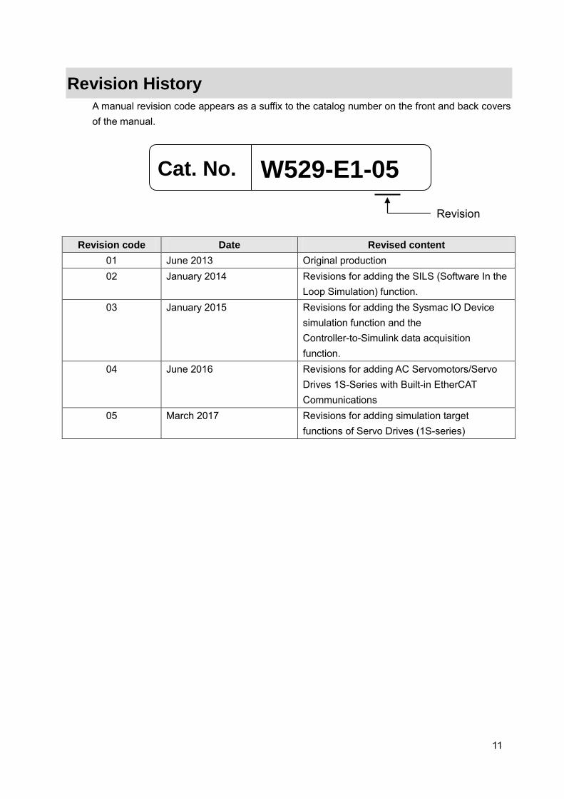
Revision History A manual revision code appears as a suffix to the catalog number on the front and back covers of the manual.
Revision code Date Revised content 01 June 2013 Original production 02 January 2014 Revisions for adding the SILS (Software In the
Loop Simulation) function. 03 January 2015 Revisions for adding the Sysmac IO Device
simulation function and the Controller-to-Simulink data acquisition function.
04 June 2016 Revisions for adding AC Servomotors/Servo Drives 1S-Series with Built-in EtherCAT Communications
05 March 2017 Revisions for adding simulation target functions of Servo Drives (1S-series)
Cat. No. W529-E1-05 Revision

12
CONTENTS Introduction .................................................................................................................. 1
Intended Audience ..................................................................................................... 1 Applicable Products ................................................................................................... 1 Special Information .................................................................................................... 1
Terms and Conditions Agreement ............................................................................. 2 NJ/NX/NY-series Controller ....................................................................................... 2 Sysmac Studio Automation Software ........................................................................ 4
Precautions .................................................................................................................. 5 Trademarks ................................................................................................................ 5 Software Licenses and Copyrights ............................................................................ 5
Related Manuals .......................................................................................................... 6 Revision History ........................................................................................................ 11 1. System to Construct and Configuration Devices ........................................... 13
1.1. System Configuration and Configuration Devices .......................................... 13 1.2. The Servo System Constructed in this Guide ................................................. 15 1.3. Sample File List ............................................................................................... 16
2. Before You Begin ............................................................................................... 17 2.1. Wiring the Devices and Installing the Software .............................................. 17 2.2. Designing the Control Algorithm ..................................................................... 19
3. Setting up the System ....................................................................................... 21 3.1. System Setup Procedures .............................................................................. 21 3.2. Simulink PLC Coder & Sysmac Studio Operation Procedure ........................ 23
3.2.1. Outputting the Code using the Simulink PLC Coder ............................. 23 3.2.2. Importing the Code into the Sysmac Studio .......................................... 25 3.2.3. Checking the Calculation Accuracy ....................................................... 27 3.2.4. Creating the EtherCAT Network Configuration ..................................... 29 3.2.5. Setting the Axis ...................................................................................... 30 3.2.6. Creating Programs ................................................................................ 32 3.2.7. Creating the Programming Terminal Screen ......................................... 35 3.2.8. Preparing the Co-simulation of Simulink and Sysmac Studio ............... 36 3.2.9. Debugging by Simulation ...................................................................... 43 3.2.10. Transferring the Programs to the CPU Unit and Servo Drive ............... 47 3.2.11. Transferring Screen Data to Programmable Terminal ........................... 48 3.2.12. System Operation Check ...................................................................... 49
4. Appendix ............................................................................................................. 56 4.1. Programming in Ladder Diagram Language .................................................. 56 4.2. Sysmac IO Device Support Models and Simulation Target Functions ........... 58
(1) Simulation Target Functions of Servo Drives (G5-series) ..................... 58 (2) Simulation Target Functions of Servo Drives (1S-series) ..................... 60 (3) Simulation Target Functions of Analog Input ......................................... 62 (4) Simulation Target Functions of Analog Output ...................................... 62

13
1. System to Construct and Configuration Devices
1.1. System Configuration and Configuration Devices This section describes the system configuration and configuration devices used in this Guide. The following figure represents the system configuration.
Precautions for Correct Use
Please start only one session each for the MATLAB and the Sysmac Studio. If more than one session is started for either of them, the co-simulation of Simulink and Sysmac Studio cannot run. Also, more than one Simulink model file cannot be executed in parallel (i.e., at the same time).
NJ-PA3001 Power Supply Unit
USB cable
Computer Sysmac Studio, MATLAB/Simulink, and Simulink PLC Coder are installed.
EtherCAT communications
cable
R88D-KNA5L-ECT
Servo Drive
Node Address 1 (Axis 0)
R88M-K05030T
Servomotor
NJ501-1300 CPU Unit
NA5-12W101S
Programmable Terminal
EtherNet/IP communications
cable

14
The models of the devices that are described in this Guide are given in the following table. When selecting devices for an actual application, refer to the device manuals. Device name Model Manual name
NJ-series CPU Unit NJ501-1300 (Unit version 1.09) NJ-series CPU Unit Hardware
User’s Manual (Cat. No. W500) NJ-series Power Supply Unit NJ-PA3001
EtherCAT communications
cables
EtherNet/IP communications
cables
XS5W-T421-CMD-K
Programmable Terminal NA5-12W101S (version 1.01) NA-series Programmable Terminal
Hardware User’s Manual (Cat. No.
V117)
AC Servo Drives R88D-KNA5L-ECT (version 2.10) AC Servomotors/Servo Drives
(Built-in EtherCAT
Communications) User's Manual
(Cat. No. I576)
AC Servomotors R88M-K05030T
Motor Power Cables
(for the AC Servo Drives)
R88A-CAKA003S
Encoder Cables
(for the AC Servo Drives)
R88A-CRKA003C
USB cable Commercially available USB cable*1 ---
*1. Use a USB2.0 (or 1.1) cable (A connector - B connector), 5.0 m max. The names and versions of the software that are used in this Guide are given below. Install the following software to a computer (OS: Windows 7 64bit). Manufacturer Name Version
OMRON Corporation Sysmac Studio Version 1.12
The MathWorks Inc. MATLAB/Simulink R2014b
The MathWorks Inc. Simulink PLC Coder R2014b

15
1.2. The Servo System Constructed in this Guide This guide describes the procedure to start up the system for single-axis positioning with a Servo Drive and Servomotor for one axis. The operations from creating the control algorithm using the Simulink® from the MathWorks® Inc. to operation check using the actual devices are given as the startup procedure. The single-axis Servo system that is set up in this Guide performs the single-axis positioning operation on the following path.
The mechanical configuration is as shown below.
Item Specifications
Servomotor Rated speed 3,000 r/min
Rotor inertia 0.025 × 10⁻⁴ kg m2
Rated torque 0.16 N m
Command pulse count per motor rotation 131,072 *1
Mechanism Work travel distance per motor rotation 96 mm
Inertia 0.375×10⁻⁴ kg m2 *2
*1. This value is set to 131,072 to match the resolution of the servomotor with 17-bit absolute encoder.
*2. Inertia ratio = Load inertia/rotor inertia x 100 % = 1500 %
Servomotor Table
Time
Position Travel distance: 100 mm
Maximum velocity: 50 mm/s
(Maximum acceleration: 185 mm/s2)
16
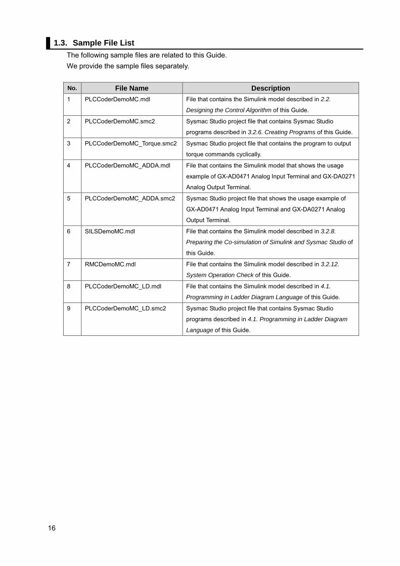
1.3. Sample File List The following sample files are related to this Guide. We provide the sample files separately.
No. File Name Description 1 PLCCoderDemoMC.mdl File that contains the Simulink model described in 2.2.
Designing the Control Algorithm of this Guide.
2 PLCCoderDemoMC.smc2 Sysmac Studio project file that contains Sysmac Studio
programs described in 3.2.6. Creating Programs of this Guide.
3 PLCCoderDemoMC_Torque.smc2 Sysmac Studio project file that contains the program to output
torque commands cyclically.
4 PLCCoderDemoMC_ADDA.mdl File that contains the Simulink model that shows the usage
example of GX-AD0471 Analog Input Terminal and GX-DA0271
Analog Output Terminal.
5 PLCCoderDemoMC_ADDA.smc2 Sysmac Studio project file that shows the usage example of
GX-AD0471 Analog Input Terminal and GX-DA0271 Analog
Output Terminal.
6 SILSDemoMC.mdl File that contains the Simulink model described in 3.2.8.
Preparing the Co-simulation of Simulink and Sysmac Studio of
this Guide.
7 RMCDemoMC.mdl File that contains the Simulink model described in 3.2.12.
System Operation Check of this Guide.
8 PLCCoderDemoMC_LD.mdl File that contains the Simulink model described in 4.1.
Programming in Ladder Diagram Language of this Guide.
9 PLCCoderDemoMC_LD.smc2 Sysmac Studio project file that contains Sysmac Studio
programs described in 4.1. Programming in Ladder Diagram
Language of this Guide.
17
2. Before You Begin
2.1. Wiring the Devices and Installing the Software You wire the devices and install the software on the computer as described in 1.1. System Configuration and Configuration Devices.
Additional Information Refer to the manuals for the devices that are used in the system for wiring of the
devices. Refer to the Sysmac Studio Version 1 Operation Manual (Cat. No. W504) for
installation of the Sysmac Studio. Access the website of The MathWorks Inc. or refer to the MATLAB & Simulink
Installation Guide that is provided by The MathWorks Inc. for installation of MATLAB/Simulink and Simulink PLC Coder.
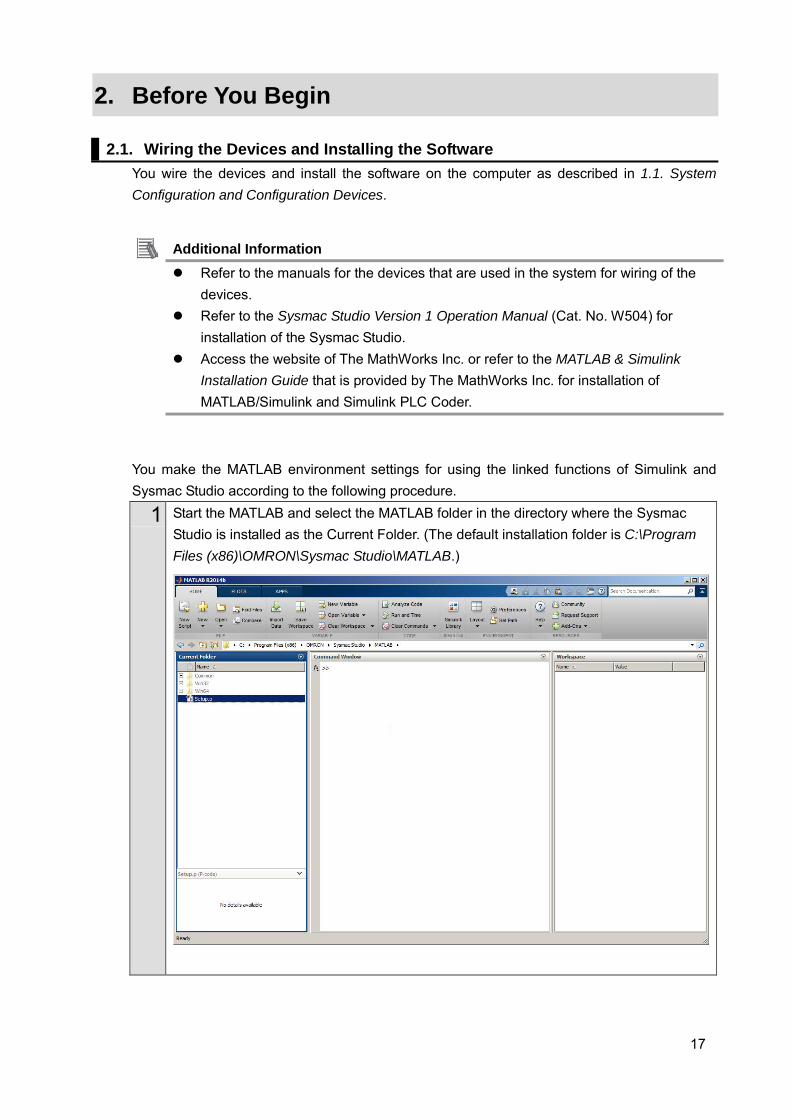
You make the MATLAB environment settings for using the linked functions of Simulink and Sysmac Studio according to the following procedure.
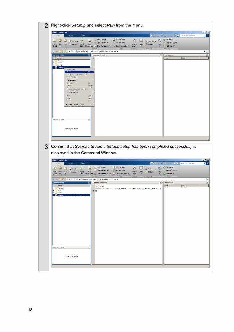
1 Start the MATLAB and select the MATLAB folder in the directory where the Sysmac Studio is installed as the Current Folder. (The default installation folder is C:\Program Files (x86)\OMRON\Sysmac Studio\MATLAB.)
18
2 Right-click Setup.p and select Run from the menu.
3 Confirm that Sysmac Studio interface setup has been completed successfully is displayed in the Command Window.
19
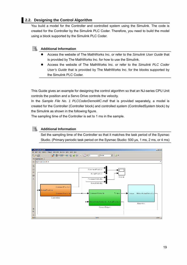
2.2. Designing the Control Algorithm You build a model for the Controller and controlled system using the Simulink. The code is created for the Controller by the Simulink PLC Coder. Therefore, you need to build the model using a block supported by the Simulink PLC Coder.
Additional Information Access the website of The MathWorks Inc. or refer to the Simulink User Guide that
is provided by The MathWorks Inc. for how to use the Simulink. Access the website of The MathWorks Inc. or refer to the Simulink PLC Coder
User’s Guide that is provided by The MathWorks Inc. for the blocks supported by the Simulink PLC Coder.
This Guide gives an example for designing the control algorithm so that an NJ-series CPU Unit controls the position and a Servo Drive controls the velocity. In the Sample File No. 1 PLCCoderDemoMC.mdl that is provided separately, a model is created for the Controller (Controller block) and controlled system (ControlledSystem block) by the Simulink as shown in the following figure. The sampling time of the Controller is set to 1 ms in the sample.
Additional Information Set the sampling time of the Controller so that it matches the task period of the Sysmac Studio. (Primary periodic task period on the Sysmac Studio: 500 μs, 1 ms, 2 ms, or 4 ms)
20
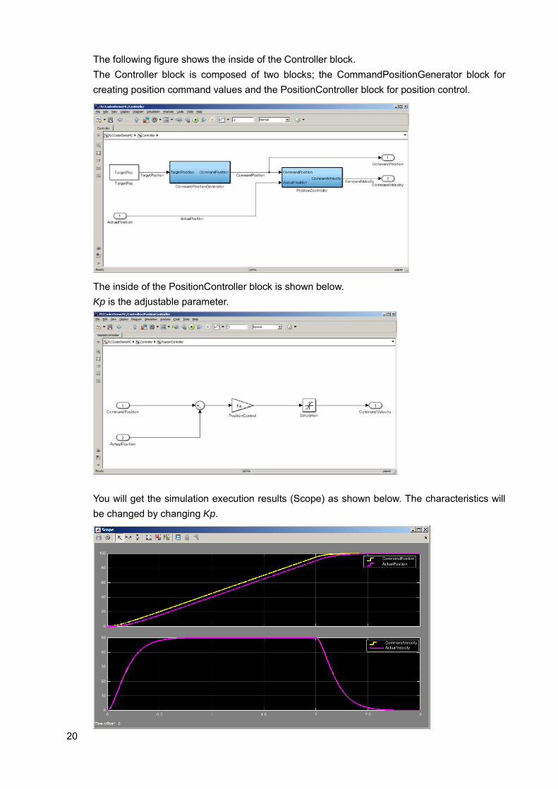
The following figure shows the inside of the Controller block. The Controller block is composed of two blocks; the CommandPositionGenerator block for creating position command values and the PositionController block for position control.
The inside of the PositionController block is shown below. Kp is the adjustable parameter.
You will get the simulation execution results (Scope) as shown below. The characteristics will be changed by changing Kp.
21
3. Setting up the System
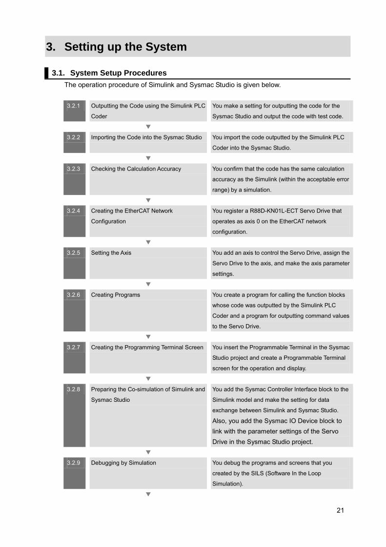
3.1. System Setup Procedures The operation procedure of Simulink and Sysmac Studio is given below.
3.2.1 Outputting the Code using the Simulink PLC
Coder
You make a setting for outputting the code for the
Sysmac Studio and output the code with test code.
▼
3.2.2 Importing the Code into the Sysmac Studio You import the code outputted by the Simulink PLC
Coder into the Sysmac Studio.
▼
3.2.3 Checking the Calculation Accuracy You confirm that the code has the same calculation
accuracy as the Simulink (within the acceptable error
range) by a simulation.
▼
3.2.4 Creating the EtherCAT Network
Configuration
You register a R88D-KN01L-ECT Servo Drive that
operates as axis 0 on the EtherCAT network
configuration.
▼
3.2.5 Setting the Axis You add an axis to control the Servo Drive, assign the
Servo Drive to the axis, and make the axis parameter
settings.
▼
3.2.6 Creating Programs You create a program for calling the function blocks
whose code was outputted by the Simulink PLC
Coder and a program for outputting command values
to the Servo Drive.
▼
3.2.7 Creating the Programming Terminal Screen You insert the Programmable Terminal in the Sysmac
Studio project and create a Programmable Terminal
screen for the operation and display.
▼
3.2.8 Preparing the Co-simulation of Simulink and
Sysmac Studio
You add the Sysmac Controller Interface block to the
Simulink model and make the setting for data
exchange between Simulink and Sysmac Studio.
Also, you add the Sysmac IO Device block to link with the parameter settings of the Servo Drive in the Sysmac Studio project.
▼
3.2.9 Debugging by Simulation You debug the programs and screens that you
created by the SILS (Software In the Loop
Simulation).
▼

22
3.2.10 Transferring the Programs to the CPU Unit
and Servo Drive
You transfer the programs and parameter settings to
the physical CPU Unit and Servo Drive.
▼
3.2.11 Transferring Screen Data to Programmable
Terminal
You transfer the screen data that you created to the
physical Programmable Terminal.
▼
3.2.12 System Operation Check You execute the operation according to the programs
transferred to the physical device and check the
operation by comparing it with the simulation using
the function for data acquisition from the NJ-series
CPU Unit to the Simulink.
23
3.2. Simulink PLC Coder & Sysmac Studio Operation Procedure
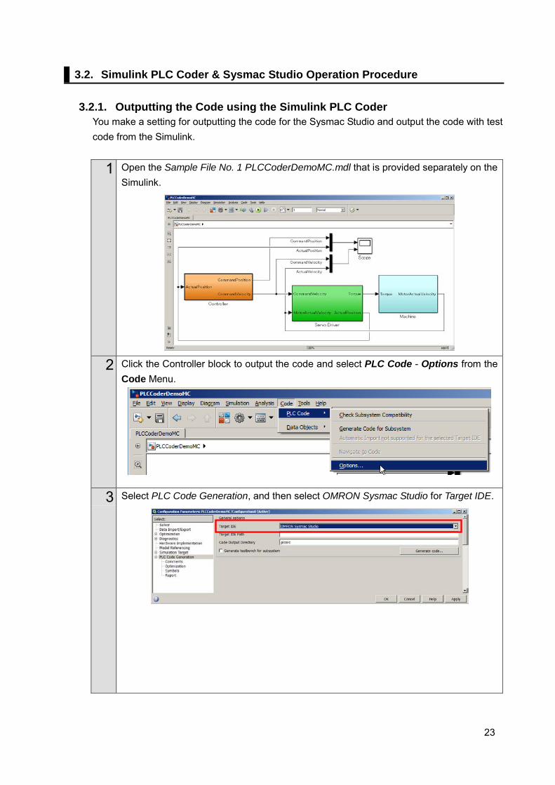
3.2.1. Outputting the Code using the Simulink PLC Coder
You make a setting for outputting the code for the Sysmac Studio and output the code with test code from the Simulink.
1 Open the Sample File No. 1 PLCCoderDemoMC.mdl that is provided separately on the Simulink.
2 Click the Controller block to output the code and select PLC Code - Options from the Code Menu.
3 Select PLC Code Generation, and then select OMRON Sysmac Studio for Target IDE.
24
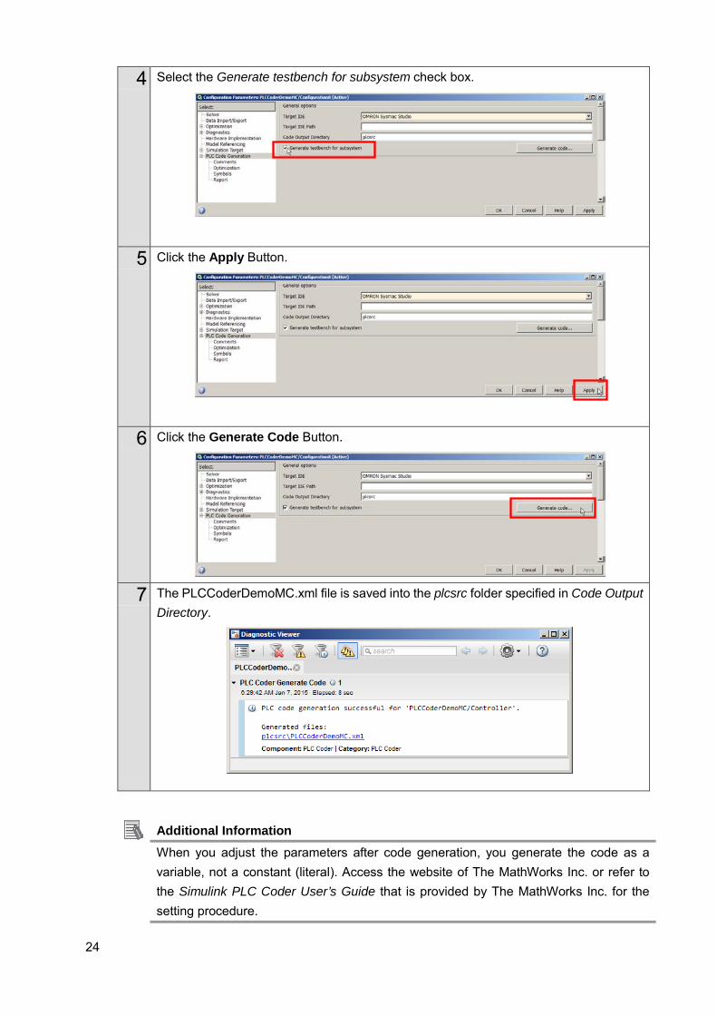
4 Select the Generate testbench for subsystem check box.
5 Click the Apply Button.
6 Click the Generate Code Button.
7 The PLCCoderDemoMC.xml file is saved into the plcsrc folder specified in Code Output Directory.
Additional Information When you adjust the parameters after code generation, you generate the code as a variable, not a constant (literal). Access the website of The MathWorks Inc. or refer to the Simulink PLC Coder User’s Guide that is provided by The MathWorks Inc. for the setting procedure.
25
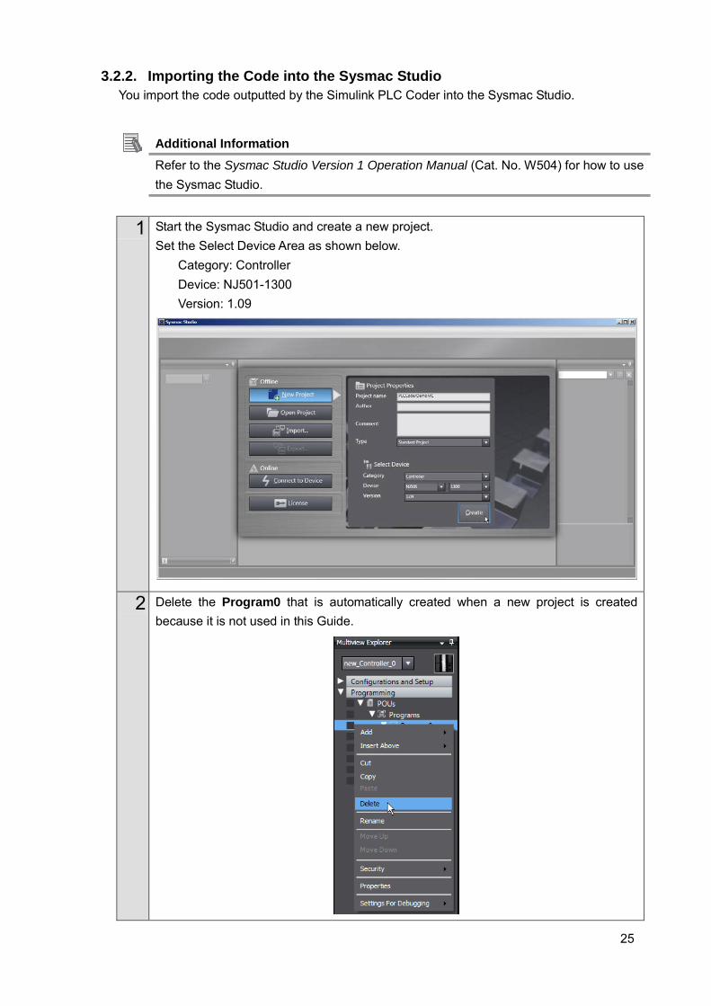
3.2.2. Importing the Code into the Sysmac Studio You import the code outputted by the Simulink PLC Coder into the Sysmac Studio.
Additional Information Refer to the Sysmac Studio Version 1 Operation Manual (Cat. No. W504) for how to use the Sysmac Studio.
1 Start the Sysmac Studio and create a new project. Set the Select Device Area as shown below.
Category: Controller Device: NJ501-1300 Version: 1.09
2 Delete the Program0 that is automatically created when a new project is created because it is not used in this Guide.
26
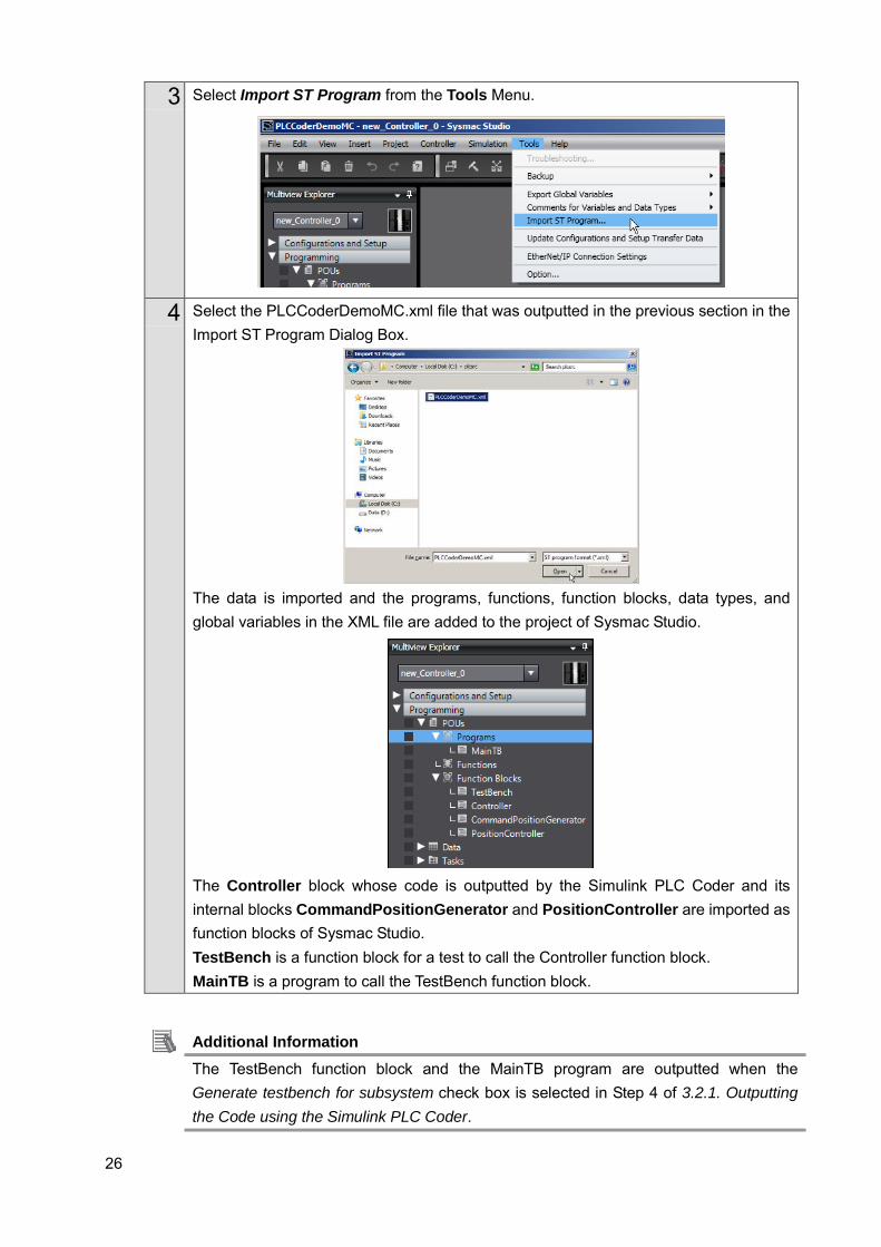
3 Select Import ST Program from the Tools Menu.
4 Select the PLCCoderDemoMC.xml file that was outputted in the previous section in the Import ST Program Dialog Box.
The data is imported and the programs, functions, function blocks, data types, and global variables in the XML file are added to the project of Sysmac Studio.
The Controller block whose code is outputted by the Simulink PLC Coder and its internal blocks CommandPositionGenerator and PositionController are imported as function blocks of Sysmac Studio. TestBench is a function block for a test to call the Controller function block. MainTB is a program to call the TestBench function block.
Additional Information The TestBench function block and the MainTB program are outputted when the Generate testbench for subsystem check box is selected in Step 4 of 3.2.1. Outputting the Code using the Simulink PLC Coder.
27
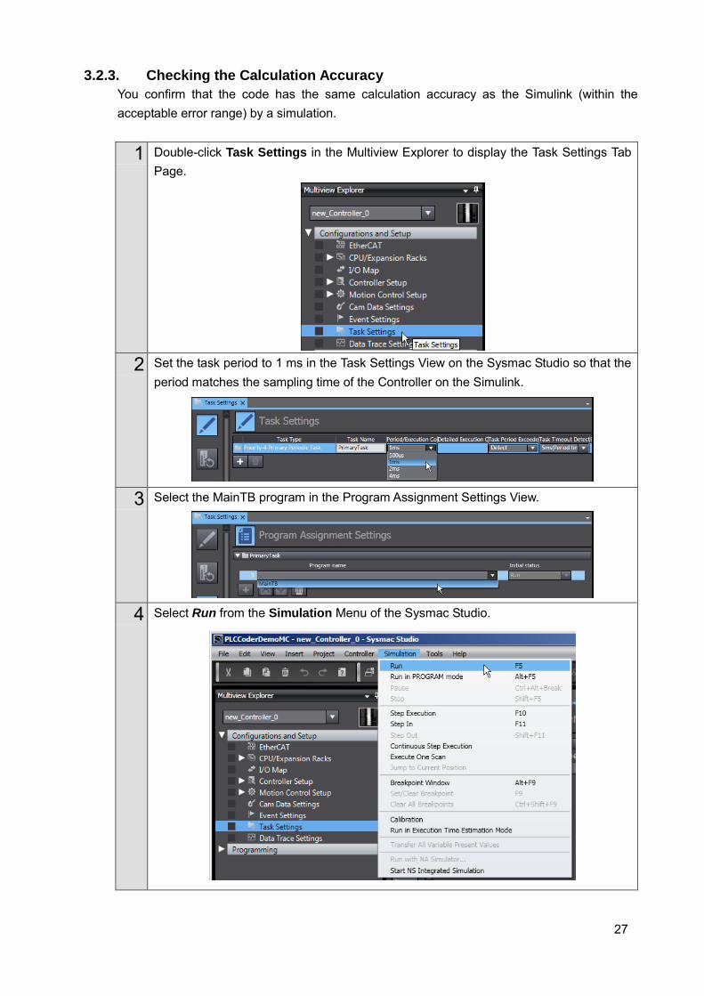
3.2.3. Checking the Calculation Accuracy You confirm that the code has the same calculation accuracy as the Simulink (within the acceptable error range) by a simulation.
1 Double-click Task Settings in the Multiview Explorer to display the Task Settings Tab Page.
2 Set the task period to 1 ms in the Task Settings View on the Sysmac Studio so that the
period matches the sampling time of the Controller on the Simulink.
3 Select the MainTB program in the Program Assignment Settings View.
4 Select Run from the Simulation Menu of the Sysmac Studio.
28
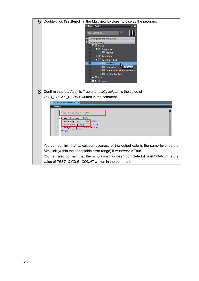
5 Double-click TestBench in the Multiview Explorer to display the program.
6 Confirm that testVerify is True and testCycleNum is the value of TEST_CYCLE_COUNT written in the comment.
You can confirm that calculation accuracy of the output data is the same level as the Simulink (within the acceptable error range) if testVerify is True. You can also confirm that the simulation has been completed if testCycleNum is the value of TEST_CYCLE_COUNT written in the comment.

29
3.2.4. Creating the EtherCAT Network Configuration You register a R88D-KNA5L-ECT Servo Drive that operates as axis 0 on the EtherCAT network configuration.
1 Double-click EtherCAT in the Multiview Explorer to display the EtherCAT Tab Page where you edit the EtherCAT network configuration.
2 Drag the R88D-KNA5L-ECT from the Toolbox to the master. The Servo Drive is added under the master with a node address of 1.
Additional Information To use digital I/O devices, analog I/O devices, and encoder input devices, add the devices using the same procedure. For data access to the devices that you added, register the device variables in the I/O Map. The examples for using GX-AD0471 Analog Input Terminal and GX-DA0271 Analog Output Terminal are provided as samples. Refer to the Sample File No. 4 PLCCoderDemoMC_ADDA.mdl and No. 5 PLCCoderDemoMC_ADDA.smc2 that are provided separately.
30
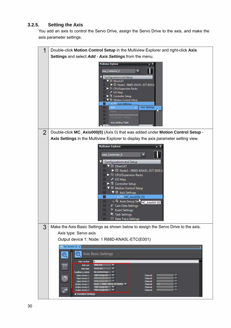
3.2.5. Setting the Axis You add an axis to control the Servo Drive, assign the Servo Drive to the axis, and make the axis parameter settings.
1 Double-click Motion Control Setup in the Multiview Explorer and right-click Axis Settings and select Add - Axis Settings from the menu.
2 Double-click MC_Axis000(0) (Axis 0) that was added under Motion Control Setup - Axis Settings in the Multiview Explorer to display the axis parameter setting view.
3 Make the Axis Basic Settings as shown below to assign the Servo Drive to the axis. Axis type: Servo axis Output device 1: Node: 1 R88D-KNA5L-ETC(E001)
31
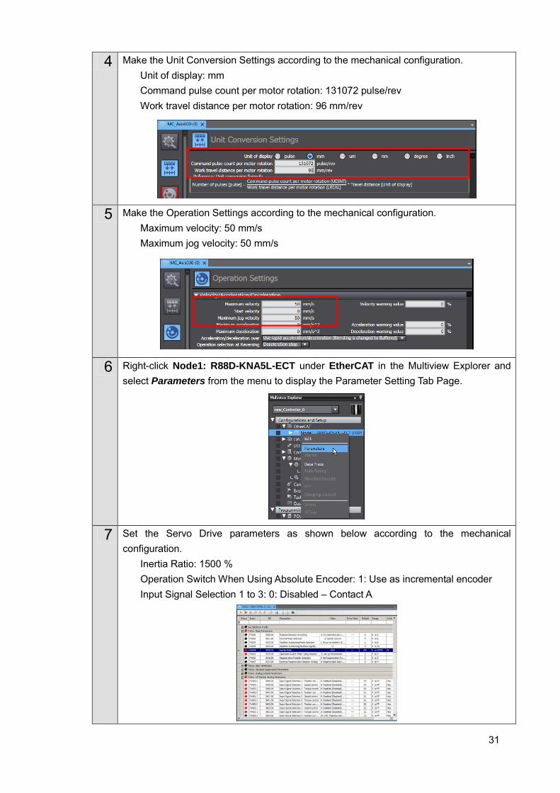
4 Make the Unit Conversion Settings according to the mechanical configuration. Unit of display: mm Command pulse count per motor rotation: 131072 pulse/rev Work travel distance per motor rotation: 96 mm/rev
5 Make the Operation Settings according to the mechanical configuration. Maximum velocity: 50 mm/s Maximum jog velocity: 50 mm/s
6 Right-click Node1: R88D-KNA5L-ECT under EtherCAT in the Multiview Explorer and select Parameters from the menu to display the Parameter Setting Tab Page.
7 Set the Servo Drive parameters as shown below according to the mechanical configuration.
Inertia Ratio: 1500 % Operation Switch When Using Absolute Encoder: 1: Use as incremental encoder Input Signal Selection 1 to 3: 0: Disabled – Contact A
32
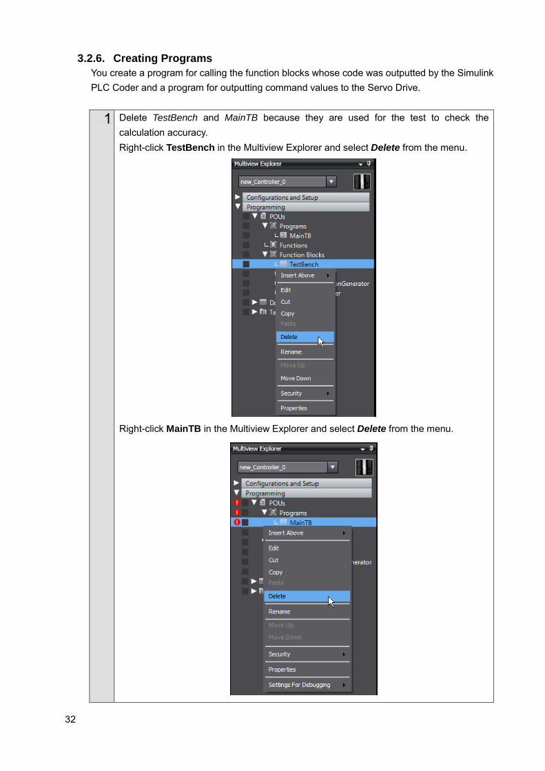
3.2.6. Creating Programs You create a program for calling the function blocks whose code was outputted by the Simulink PLC Coder and a program for outputting command values to the Servo Drive.
1 Delete TestBench and MainTB because they are used for the test to check the calculation accuracy. Right-click TestBench in the Multiview Explorer and select Delete from the menu.
Right-click MainTB in the Multiview Explorer and select Delete from the menu.
33
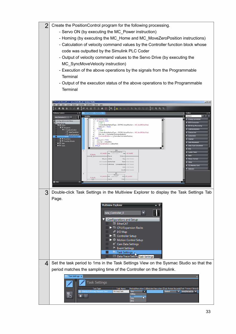
2 Create the PositionControl program for the following processing. - Servo ON (by executing the MC_Power instruction) - Homing (by executing the MC_Home and MC_MoveZeroPosition instructions) - Calculation of velocity command values by the Controller function block whose
code was outputted by the Simulink PLC Coder - Output of velocity command values to the Servo Drive (by executing the
MC_SyncMoveVelocity instruction) - Execution of the above operations by the signals from the Programmable
Terminal - Output of the execution status of the above operations to the Programmable
Terminal
3 Double-click Task Settings in the Multiview Explorer to display the Task Settings Tab Page.
4 Set the task period to 1ms in the Task Settings View on the Sysmac Studio so that the
period matches the sampling time of the Controller on the Simulink.
34
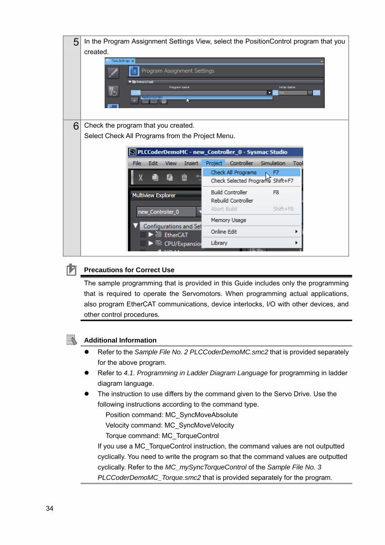
5 In the Program Assignment Settings View, select the PositionControl program that you created.
6 Check the program that you created. Select Check All Programs from the Project Menu.
Additional Information Refer to the Sample File No. 2 PLCCoderDemoMC.smc2 that is provided separately
for the above program. Refer to 4.1. Programming in Ladder Diagram Language for programming in ladder
diagram language. The instruction to use differs by the command given to the Servo Drive. Use the
following instructions according to the command type. Position command: MC_SyncMoveAbsolute Velocity command: MC_SyncMoveVelocity Torque command: MC_TorqueControl
If you use a MC_TorqueControl instruction, the command values are not outputted cyclically. You need to write the program so that the command values are outputted cyclically. Refer to the MC_mySyncTorqueControl of the Sample File No. 3 PLCCoderDemoMC_Torque.smc2 that is provided separately for the program.
Precautions for Correct Use
The sample programming that is provided in this Guide includes only the programming that is required to operate the Servomotors. When programming actual applications, also program EtherCAT communications, device interlocks, I/O with other devices, and other control procedures.
35
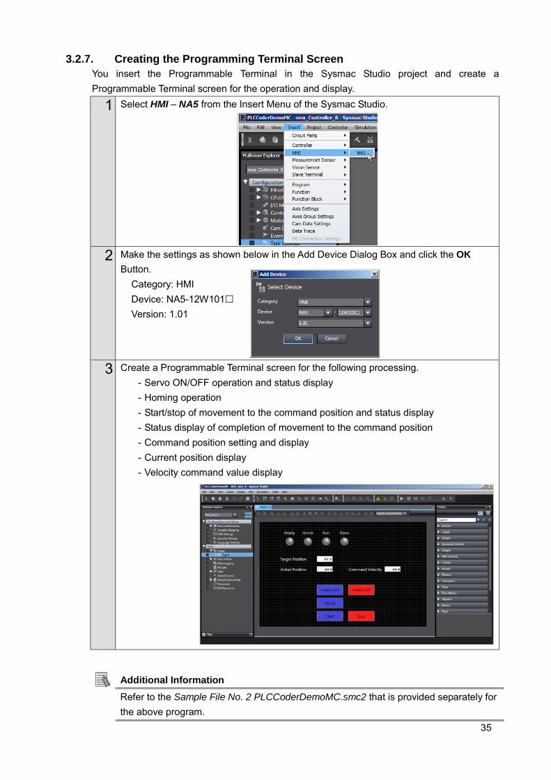
3.2.7. Creating the Programming Terminal Screen You insert the Programmable Terminal in the Sysmac Studio project and create a Programmable Terminal screen for the operation and display.
1 Select HMI – NA5 from the Insert Menu of the Sysmac Studio.
2 Make the settings as shown below in the Add Device Dialog Box and click the OK
Button. Category: HMI Device: NA5-12W101 Version: 1.01
3 Create a Programmable Terminal screen for the following processing. - Servo ON/OFF operation and status display - Homing operation - Start/stop of movement to the command position and status display - Status display of completion of movement to the command position - Command position setting and display - Current position display - Velocity command value display
Additional Information Refer to the Sample File No. 2 PLCCoderDemoMC.smc2 that is provided separately for the above program.
36
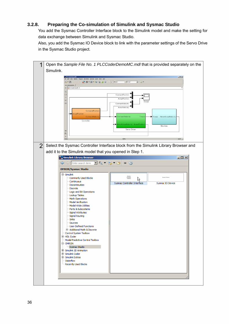
3.2.8. Preparing the Co-simulation of Simulink and Sysmac Studio You add the Sysmac Controller Interface block to the Simulink model and make the setting for data exchange between Simulink and Sysmac Studio. Also, you add the Sysmac IO Device block to link with the parameter settings of the Servo Drive in the Sysmac Studio project.
1 Open the Sample File No. 1 PLCCoderDemoMC.mdl that is provided separately on the Simulink.
2 Select the Sysmac Controller Interface block from the Simulink Library Browser and add it to the Simulink model that you opened in Step 1.

37
3 Double-click the Sysmac Controller Interface block that you added in Step 2 and display the dialog box where to make the setting for data exchange between Simulink and Sysmac Studio’s Simulator.
4 Select MC_Axis000.Act.Pos from the list of variables in the Sysmac Studio project and
click the Register Button for the In list to pass the actual current position calculated by the Simulink to the Sysmac Studio’s Simulator.
5 Select CommandPosition from the list of variables in the Sysmac Studio project and
click the Register Button for the Out list to pass the position command value calculated by the Sysmac Studio’s Simulator to the Simulink.
38
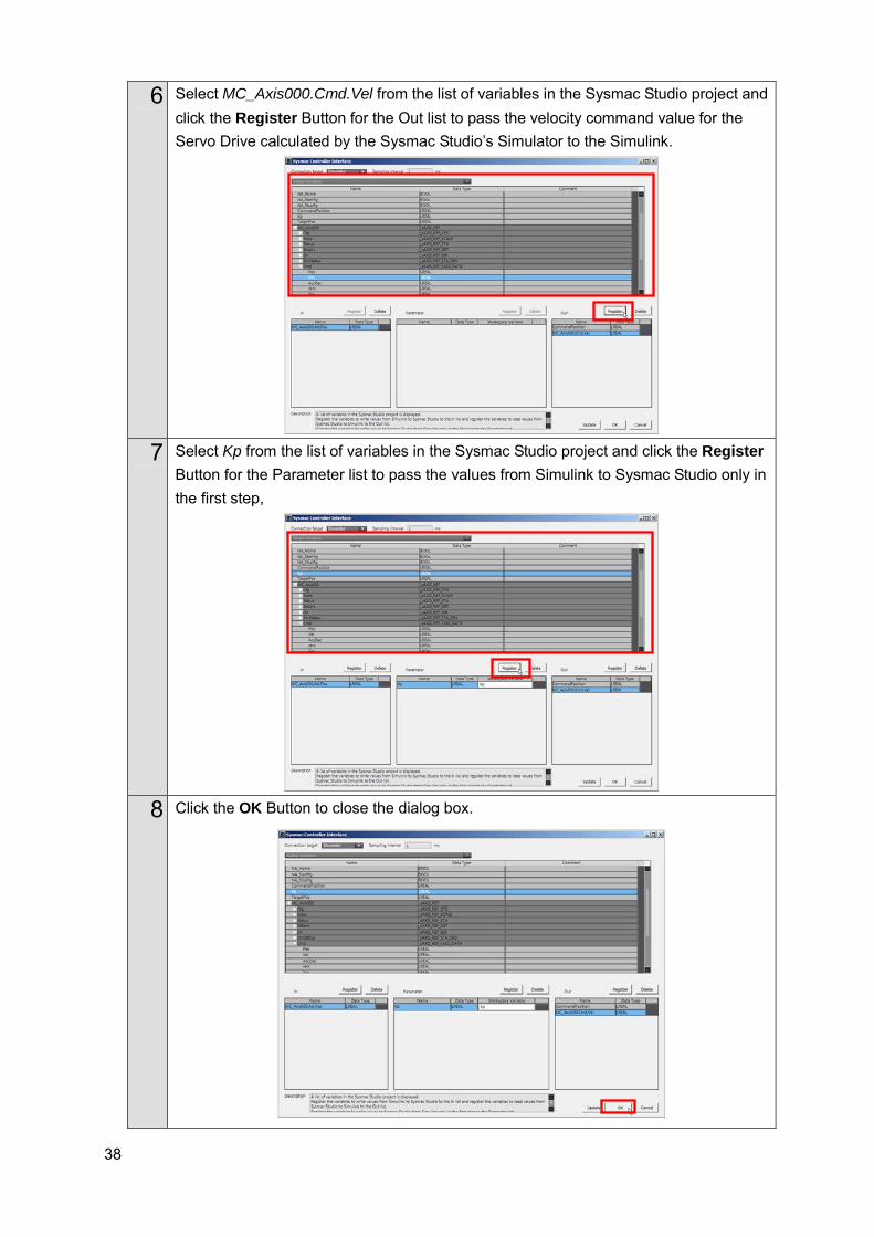
6 Select MC_Axis000.Cmd.Vel from the list of variables in the Sysmac Studio project and click the Register Button for the Out list to pass the velocity command value for the Servo Drive calculated by the Sysmac Studio’s Simulator to the Simulink.
7 Select Kp from the list of variables in the Sysmac Studio project and click the Register
Button for the Parameter list to pass the values from Simulink to Sysmac Studio only in the first step,
8 Click the OK Button to close the dialog box.
39
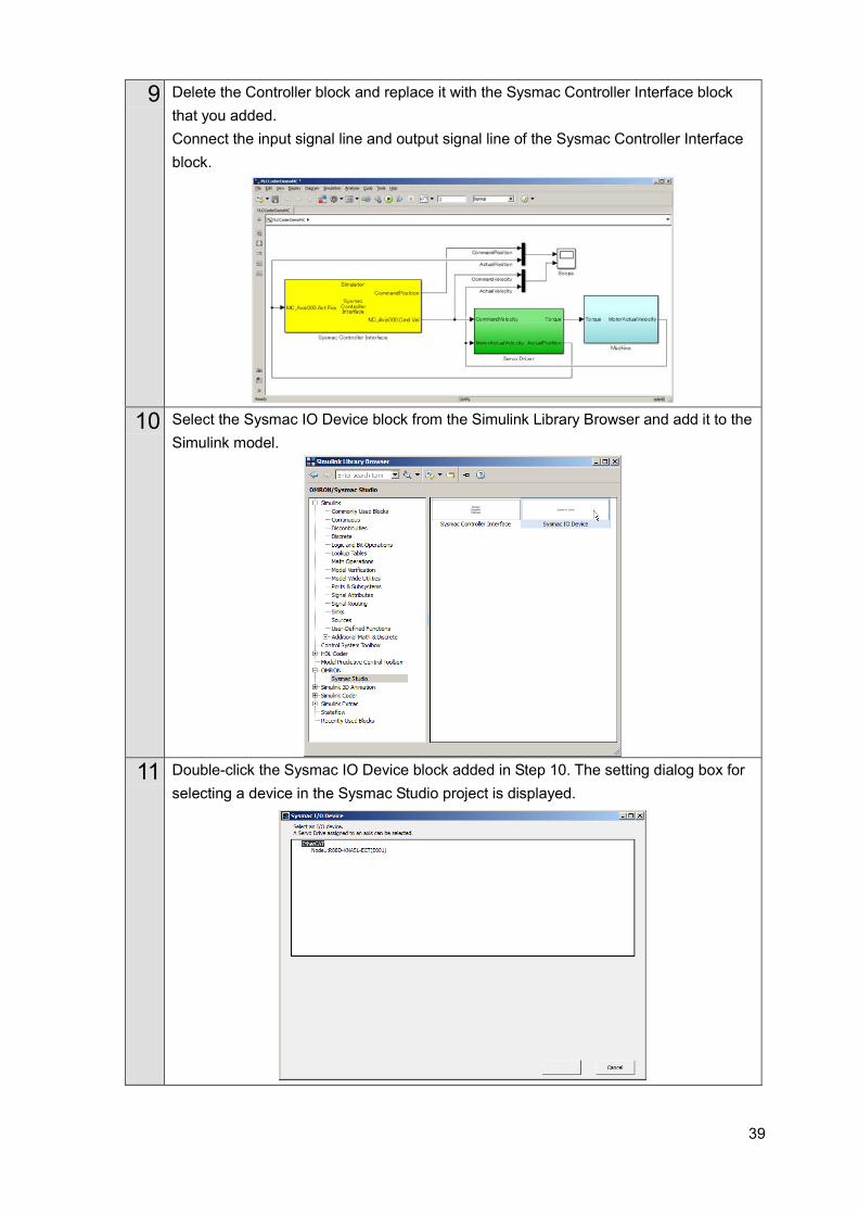
9 Delete the Controller block and replace it with the Sysmac Controller Interface block that you added. Connect the input signal line and output signal line of the Sysmac Controller Interface block.
10 Select the Sysmac IO Device block from the Simulink Library Browser and add it to the
Simulink model.
11 Double-click the Sysmac IO Device block added in Step 10. The setting dialog box for
selecting a device in the Sysmac Studio project is displayed.
40
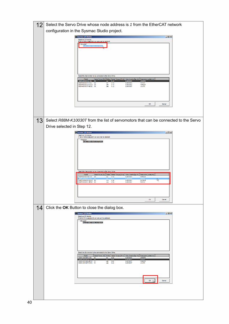
12 Select the Servo Drive whose node address is 1 from the EtherCAT network configuration in the Sysmac Studio project.
13 Select R88M-K10030T from the list of servomotors that can be connected to the Servo Drive selected in Step 12.
14 Click the OK Button to close the dialog box.
41
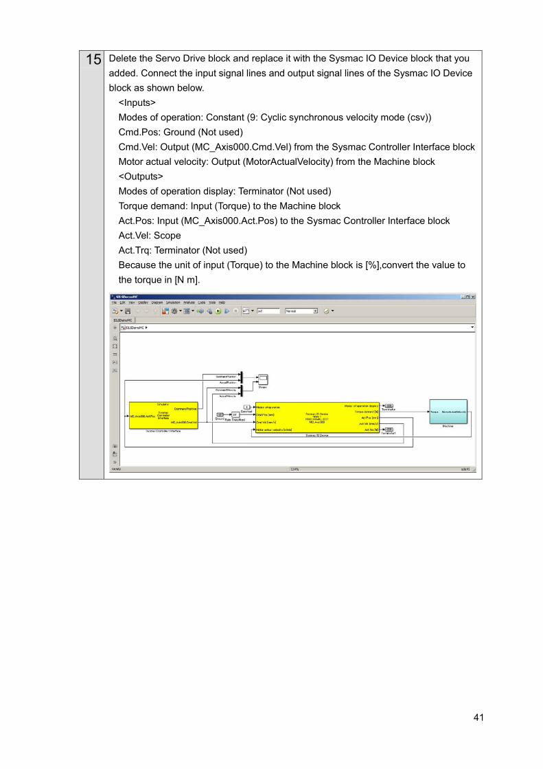
15 Delete the Servo Drive block and replace it with the Sysmac IO Device block that you added. Connect the input signal lines and output signal lines of the Sysmac IO Device block as shown below.
<Inputs> Modes of operation: Constant (9: Cyclic synchronous velocity mode (csv)) Cmd.Pos: Ground (Not used) Cmd.Vel: Output (MC_Axis000.Cmd.Vel) from the Sysmac Controller Interface block Motor actual velocity: Output (MotorActualVelocity) from the Machine block <Outputs> Modes of operation display: Terminator (Not used) Torque demand: Input (Torque) to the Machine block Act.Pos: Input (MC_Axis000.Act.Pos) to the Sysmac Controller Interface block Act.Vel: Scope Act.Trq: Terminator (Not used) Because the unit of input (Torque) to the Machine block is [%],convert the value to the torque in [N m].
42
Additional Information Refer to the Sample File No. 6 SILSDemoMC.mdl for the Simulink model that you
created by the above operation. You can add the following axis variable members to the In list.
However, you can add only the axes whose Axis use parameter is set to Unused axis (changeable to used axis) or Used axis and whose Axis type parameter is set to Servo axis or Encoder axis. Like the actual access from Servo Drive or encoder to Controller, these variables are converted to the data type for the PDO communications (Act.Pos and Act.Vel are converted to DINT data and Act.Trq is converted to INT data) for unit conversion of axis variables (i.e., calculation based on the electronic gear ratio setting) using the command pulse count per motor rotation and work travel distance per motor rotation.
The Modes of operation input to the Sysmac IO Device block is corresponding to the operation mode of the process data object (PDO) of the AC Servomotor/Servo Drives G5/1S-series with built-in EtherCAT communications (6060 hex) and refers to 8: Cyclic synchronous position mode (csp), 9: Cyclic synchronous velocity mode (csv), or 10: Cyclic synchronous torque mode (cst).
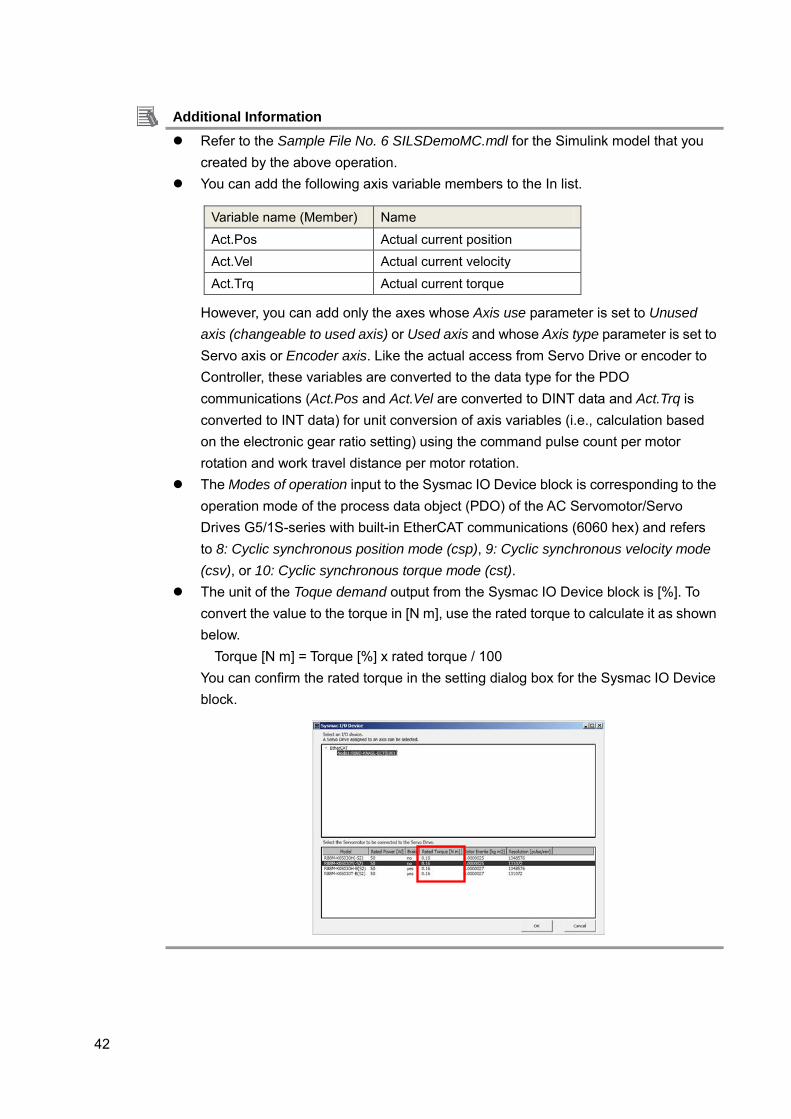
The unit of the Toque demand output from the Sysmac IO Device block is [%]. To convert the value to the torque in [N m], use the rated torque to calculate it as shown below. Torque [N m] = Torque [%] x rated torque / 100 You can confirm the rated torque in the setting dialog box for the Sysmac IO Device block.
Variable name (Member) Name
Act.Pos Actual current position Act.Vel Actual current velocity
Act.Trq Actual current torque
43
3.2.9. Debugging by Simulation You debug the programs and screens that you created by the SILS (Software In the Loop Simulation).
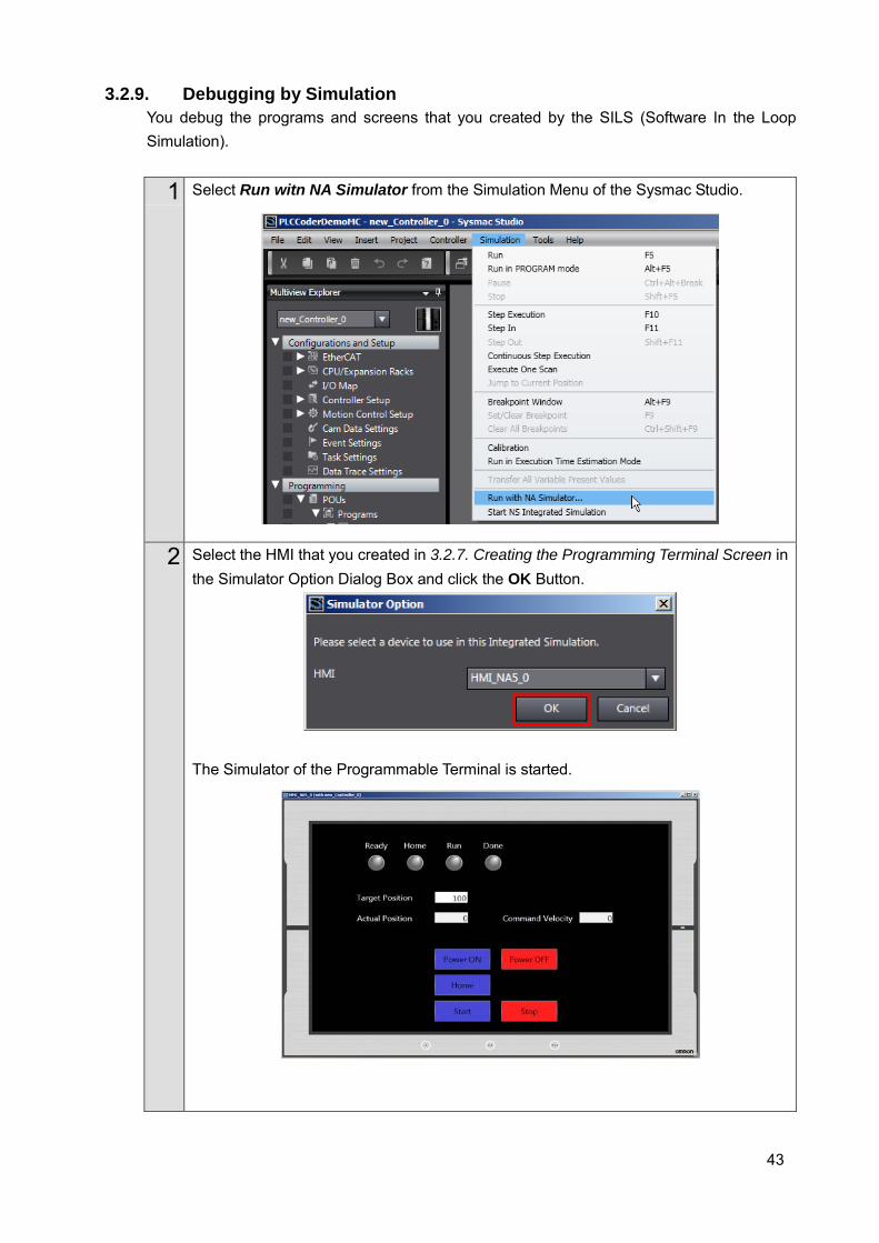
1 Select Run witn NA Simulator from the Simulation Menu of the Sysmac Studio.
2 Select the HMI that you created in 3.2.7. Creating the Programming Terminal Screen in the Simulator Option Dialog Box and click the OK Button.
The Simulator of the Programmable Terminal is started.
44
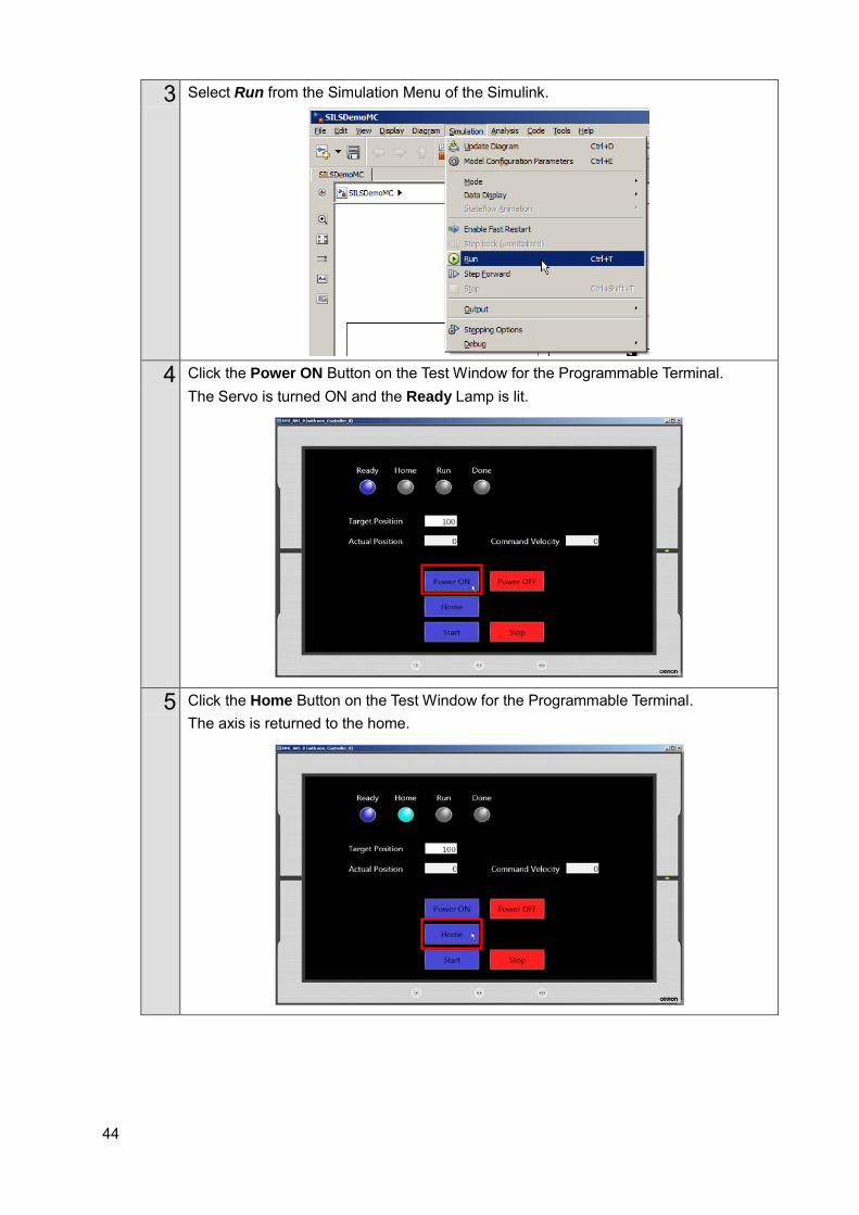
3 Select Run from the Simulation Menu of the Simulink.
4 Click the Power ON Button on the Test Window for the Programmable Terminal. The Servo is turned ON and the Ready Lamp is lit.
5 Click the Home Button on the Test Window for the Programmable Terminal. The axis is returned to the home.

45
6 Click the Start Button on the Test Window for the Programmable Terminal. The axis starts moving to the Target Position and the Run Lamp is lit. The Actual Position value and Command Velocity value change. When the movement is completed, the Done Lamp is lit.
7 Check the simulation results (Scope) of the Simulink. You can confirm that you got the similar results as the waveform shown in 1.2. The Servo System Constructed in this Guide and 2.2. Designing the Control Algorithm.
8 Use the following procedure to stop the simulation. Select Stop from the Simulation Menu of the Simulink.
46
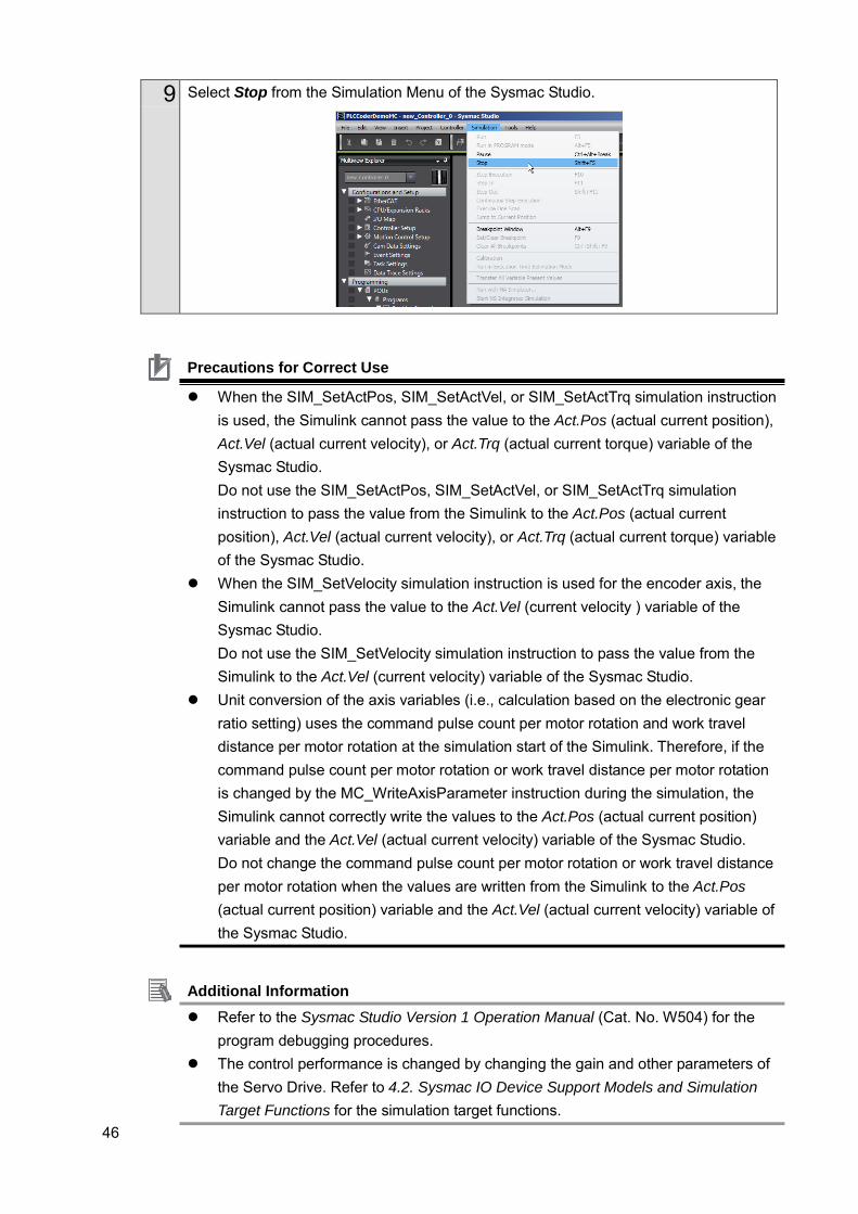
9 Select Stop from the Simulation Menu of the Sysmac Studio.
Precautions for Correct Use
When the SIM_SetActPos, SIM_SetActVel, or SIM_SetActTrq simulation instruction is used, the Simulink cannot pass the value to the Act.Pos (actual current position), Act.Vel (actual current velocity), or Act.Trq (actual current torque) variable of the Sysmac Studio. Do not use the SIM_SetActPos, SIM_SetActVel, or SIM_SetActTrq simulation instruction to pass the value from the Simulink to the Act.Pos (actual current position), Act.Vel (actual current velocity), or Act.Trq (actual current torque) variable of the Sysmac Studio.
When the SIM_SetVelocity simulation instruction is used for the encoder axis, the Simulink cannot pass the value to the Act.Vel (current velocity ) variable of the Sysmac Studio. Do not use the SIM_SetVelocity simulation instruction to pass the value from the Simulink to the Act.Vel (current velocity) variable of the Sysmac Studio.
Unit conversion of the axis variables (i.e., calculation based on the electronic gear ratio setting) uses the command pulse count per motor rotation and work travel distance per motor rotation at the simulation start of the Simulink. Therefore, if the command pulse count per motor rotation or work travel distance per motor rotation is changed by the MC_WriteAxisParameter instruction during the simulation, the Simulink cannot correctly write the values to the Act.Pos (actual current position) variable and the Act.Vel (actual current velocity) variable of the Sysmac Studio. Do not change the command pulse count per motor rotation or work travel distance per motor rotation when the values are written from the Simulink to the Act.Pos (actual current position) variable and the Act.Vel (actual current velocity) variable of the Sysmac Studio.
Additional Information Refer to the Sysmac Studio Version 1 Operation Manual (Cat. No. W504) for the
program debugging procedures. The control performance is changed by changing the gain and other parameters of
the Servo Drive. Refer to 4.2. Sysmac IO Device Support Models and Simulation Target Functions for the simulation target functions.
47
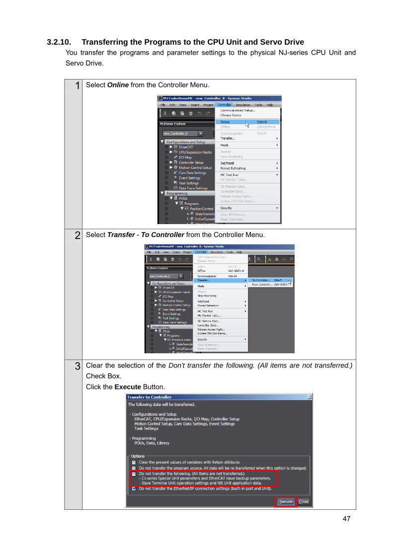
3.2.10. Transferring the Programs to the CPU Unit and Servo Drive You transfer the programs and parameter settings to the physical NJ-series CPU Unit and Servo Drive.
1 Select Online from the Controller Menu.
2 Select Transfer - To Controller from the Controller Menu.
3 Clear the selection of the Don’t transfer the following. (All items are not transferred.) Check Box. Click the Execute Button.
48
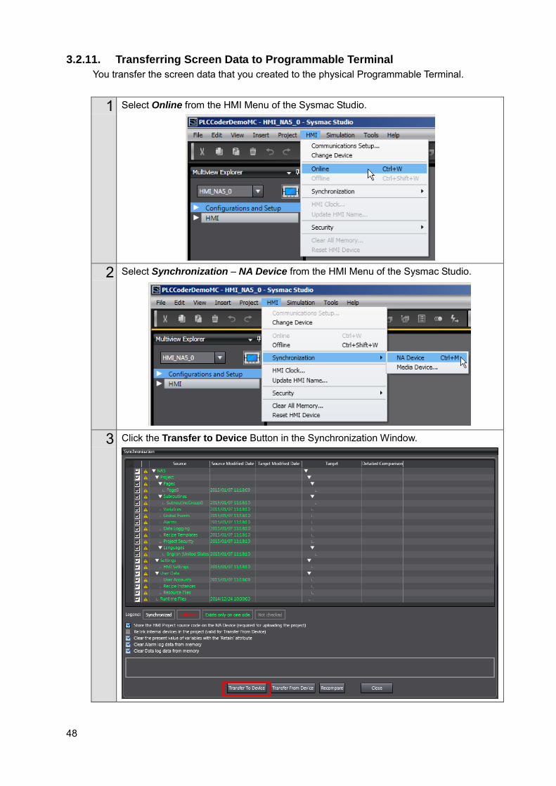
3.2.11. Transferring Screen Data to Programmable Terminal You transfer the screen data that you created to the physical Programmable Terminal.
1 Select Online from the HMI Menu of the Sysmac Studio.
2 Select Synchronization – NA Device from the HMI Menu of the Sysmac Studio.
3 Click the Transfer to Device Button in the Synchronization Window.
49
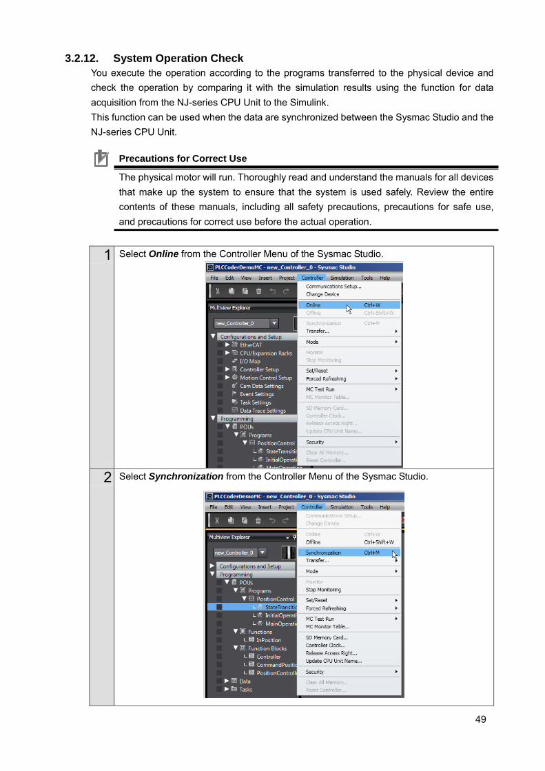
3.2.12. System Operation Check You execute the operation according to the programs transferred to the physical device and check the operation by comparing it with the simulation results using the function for data acquisition from the NJ-series CPU Unit to the Simulink. This function can be used when the data are synchronized between the Sysmac Studio and the NJ-series CPU Unit.
1 Select Online from the Controller Menu of the Sysmac Studio.
2 Select Synchronization from the Controller Menu of the Sysmac Studio.
Precautions for Correct Use
The physical motor will run. Thoroughly read and understand the manuals for all devices that make up the system to ensure that the system is used safely. Review the entire contents of these manuals, including all safety precautions, precautions for safe use, and precautions for correct use before the actual operation.
50
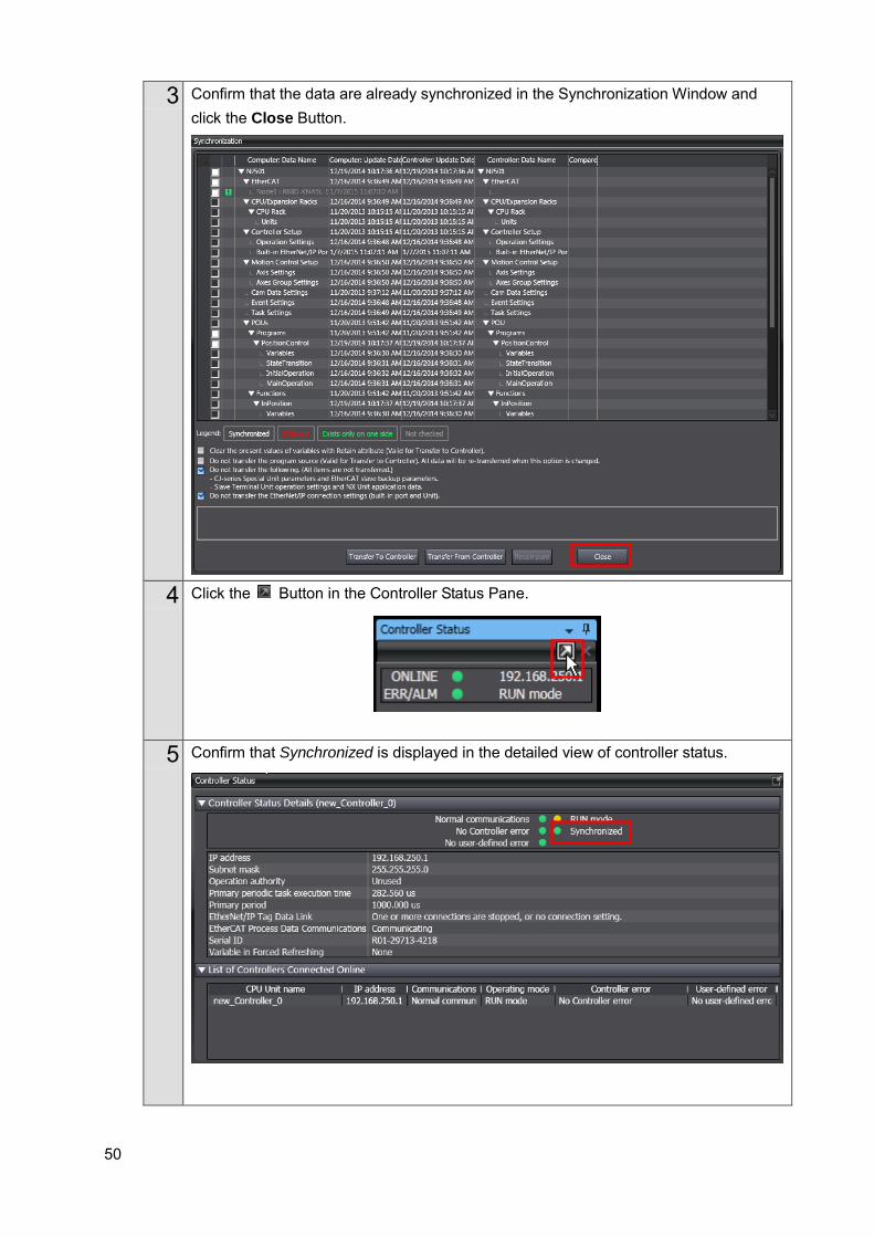
3 Confirm that the data are already synchronized in the Synchronization Window and click the Close Button.
4 Click the Button in the Controller Status Pane.
5 Confirm that Synchronized is displayed in the detailed view of controller status.
51
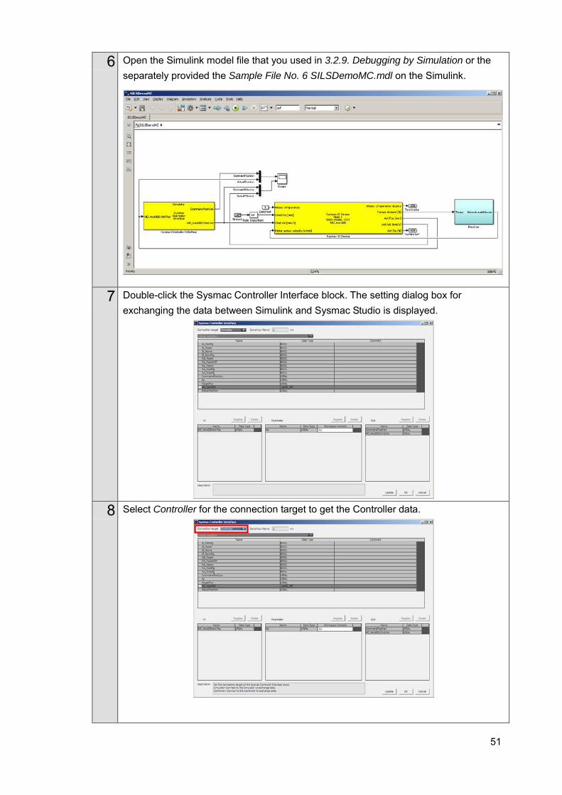
6 Open the Simulink model file that you used in 3.2.9. Debugging by Simulation or the separately provided the Sample File No. 6 SILSDemoMC.mdl on the Simulink.
7 Double-click the Sysmac Controller Interface block. The setting dialog box for exchanging the data between Simulink and Sysmac Studio is displayed.
8 Select Controller for the connection target to get the Controller data.

52
9 Because the In list is not used, delete the variable in the list. Select MC_Axis000.Act.Pos and click the Delete Button.
10 In order to pass the actual current position and actual current velocity of the NJ-series CPU Unit to the Simulink, select MC_Axis000.Act.Pos and MC_Axis000.Act.Vel from the list of variables in the Sysmac Studio project and click the Register Button for the Out list.
11 Click the OK Button to close the dialog box.
53
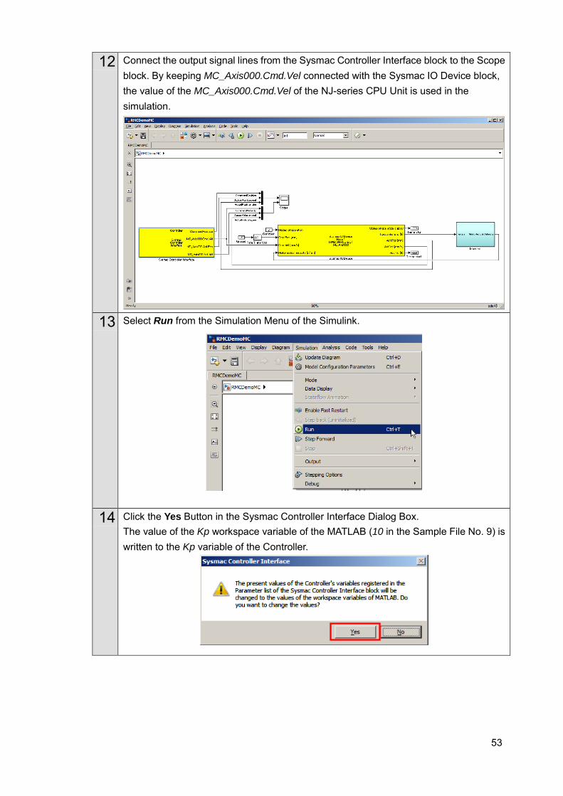
12 Connect the output signal lines from the Sysmac Controller Interface block to the Scope block. By keeping MC_Axis000.Cmd.Vel connected with the Sysmac IO Device block, the value of the MC_Axis000.Cmd.Vel of the NJ-series CPU Unit is used in the simulation.
13 Select Run from the Simulation Menu of the Simulink.
14 Click the Yes Button in the Sysmac Controller Interface Dialog Box. The value of the Kp workspace variable of the MATLAB (10 in the Sample File No. 9) is written to the Kp variable of the Controller.

54
15 Press the Power ON Button on the physical Programmable Terminal. The Servo is turned ON and the Ready Lamp is lit.
16 Press the Home Button on the physical Programmable Terminal. The axis is returned to the home.
17 Press the Start Button on the physical Programmable Terminal. The axis starts moving to the Target Position and the Run Lamp is lit. The Actual Position value and Command Velocity value change. When the movement is completed, the Done Lamp is lit.
55
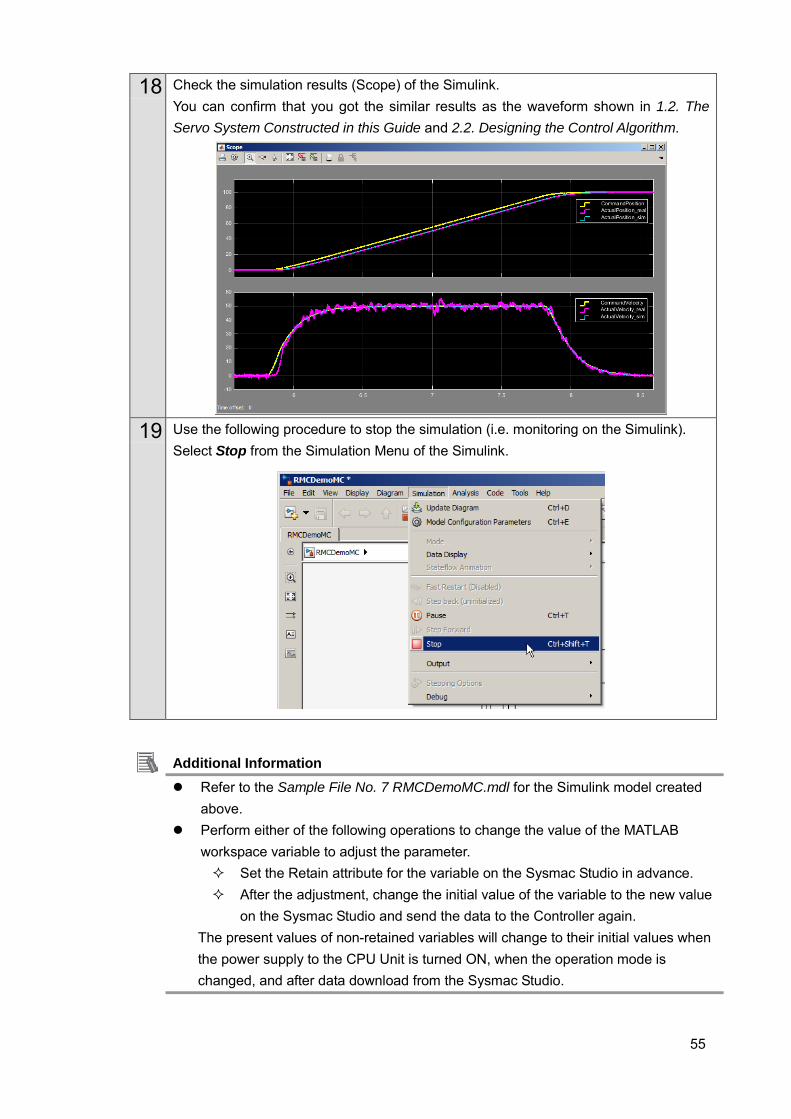
18 Check the simulation results (Scope) of the Simulink. You can confirm that you got the similar results as the waveform shown in 1.2. The Servo System Constructed in this Guide and 2.2. Designing the Control Algorithm.
19 Use the following procedure to stop the simulation (i.e. monitoring on the Simulink).
Select Stop from the Simulation Menu of the Simulink.
Additional Information Refer to the Sample File No. 7 RMCDemoMC.mdl for the Simulink model created
above. Perform either of the following operations to change the value of the MATLAB
workspace variable to adjust the parameter. Set the Retain attribute for the variable on the Sysmac Studio in advance. After the adjustment, change the initial value of the variable to the new value
on the Sysmac Studio and send the data to the Controller again. The present values of non-retained variables will change to their initial values when the power supply to the CPU Unit is turned ON, when the operation mode is changed, and after data download from the Sysmac Studio.
56
4. Appendix
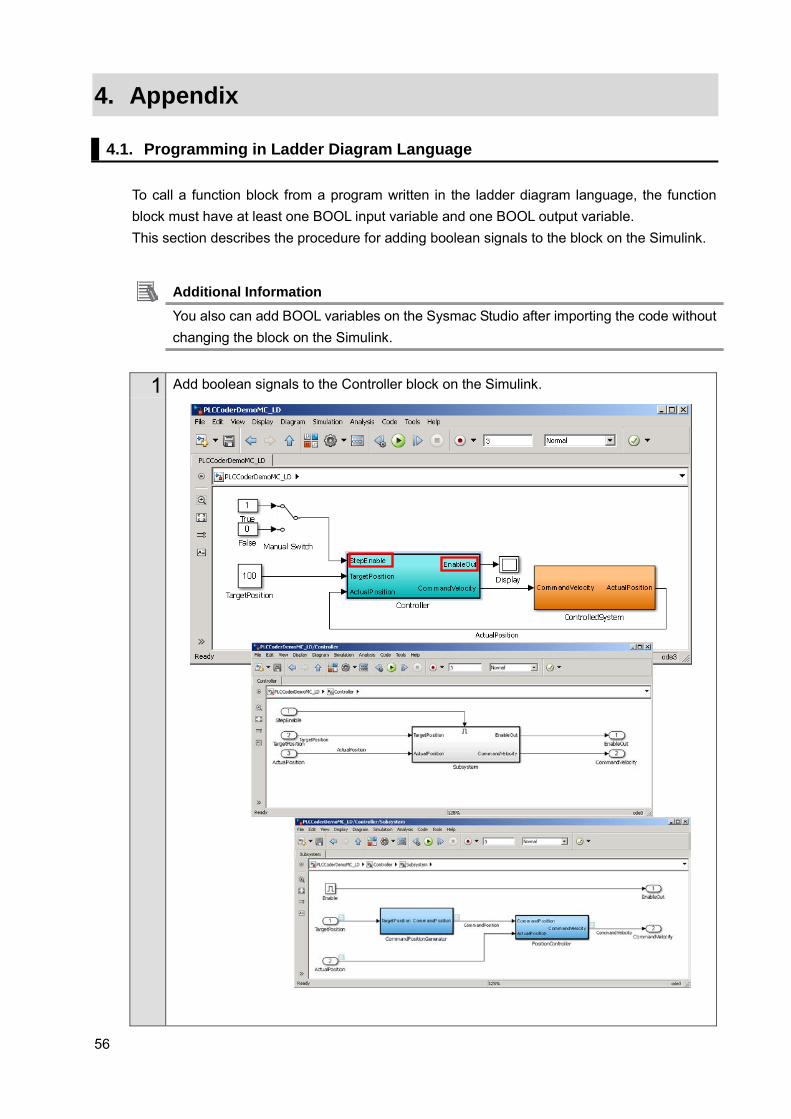
4.1. Programming in Ladder Diagram Language To call a function block from a program written in the ladder diagram language, the function block must have at least one BOOL input variable and one BOOL output variable. This section describes the procedure for adding boolean signals to the block on the Simulink.
Additional Information You also can add BOOL variables on the Sysmac Studio after importing the code without changing the block on the Simulink.
1 Add boolean signals to the Controller block on the Simulink.
57
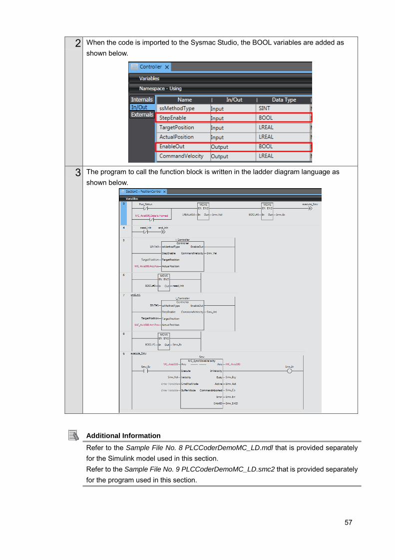
2 When the code is imported to the Sysmac Studio, the BOOL variables are added as shown below.
3 The program to call the function block is written in the ladder diagram language as shown below.
Additional Information Refer to the Sample File No. 8 PLCCoderDemoMC_LD.mdl that is provided separately for the Simulink model used in this section. Refer to the Sample File No. 9 PLCCoderDemoMC_LD.smc2 that is provided separately for the program used in this section.
58
4.2. Sysmac IO Device Support Models and Simulation Target Functions The following models can be selected for Sysmac IO Device.
No. Category Target Model
1 Servo Drive AC Servo Drives [G5-series Servo Drives with EtherCAT
communications]
R88D-KN-ECT
AC Servo Drives [G5-series Linear Servo Drives with
EtherCAT communications]
R88D-KN-ECT-L
2 Servo Drive AC Servo Drives [1S-series Servo Drives with EtherCAT
communications]
R88D-1SN-ECT
3 Analog Input GX-series EtherCAT Remote I/O Terminal GX-AD0471
NX-series EtherCAT Slave Terminals NX-AD
4 Analog Output GX-series EtherCAT Remote I/O Terminal GX-DA0271
NX-series EtherCAT Slave Terminals NX-DA
(1) Simulation Target Functions of Servo Drives (G5-series) The control mode is switched between position control mode and velocity control mode by specifying 8: Cyclic synchronous position mode (csp) or 9: Cyclic synchronous velocity mode (csv) in the Modes of operation input to the Sysmac IO Device block. Torque control mode and control mode change during simulation are not supported.
Function No. Name
Smoothing filter
(first-order lag filter) Pn222 Position Command Filter Time Constant
Damping control
Pn213 Damping Filter Selection (Only “0” is supported. Even if other value is
set, it operates as if “0” is set.)
Pn214 Damping Frequency 1
Pn215 Damping Filter 1 Setting
Pn216 Damping Frequency 2
Pn217 Damping Filter 2 Setting
Speed Feed-forward Pn110 Speed Feed-forward Gain
Pn111 Speed Feed-forward Command Filter
Gain switching
(Only “Always gain 1” and
“Always gain 2” are
supported.)
Pn114 Gain Switching Input Operation Mode Selection
Pn115 Switching Mode in Position Control (Only “0”, “1”, and “4” are supported.
If other value is set, it operates as if “0: Always gain 1” is set.)
Pn120 Switching Mode in Speed Control (Only “0” and “1” are supported. If
other value is set, it operates as if “0: Always gain 1” is set.)
Position control Pn100 Position Loop Gain 1
Pn105 Position Loop Gain 2
Speed control
Pn101 Speed Loop Gain 1
Pn106 Speed Loop Gain 2
Pn102 Speed Loop Integral Time Constant 1
Pn107 Speed Loop Integral Time Constant 2
Pn004 Inertia Ratio
59
Function No. Name
Notch filter
Pn201 Notch 1 Frequency Setting
Pn202 Notch 1 Width Setting
Pn203 Notch 1 Depth Setting
Pn204 Notch 2 Frequency Setting
Pn205 Notch 2 Width Setting
Pn206 Notch 2 Depth Setting
Pn207 Notch 3 Frequency Setting
Pn208 Notch 3 Width Setting
Pn209 Notch 3 Depth Setting
Pn210 Notch 4 Frequency Setting
Pn211 Notch 4 Width Setting
Pn212 Notch 4 Depth Setting
Torque (Force) filter Pn104 Torque (Force) Command Filter Time Constant 1
Pn109 Torque (Force) Command Filter Time Constant 2
Torque (Force) limit
Pn753 External Torque (Force) Limit 1 (PDO: 3013 hex)
Pn754 External Torque (Force) Limit 2 (PDO: 3522 hex)
Axis setting Positive Torque Limit (PDO: 60E0 hex)
Axis setting Negative Torque Limit (PDO: 60E1 hex)
Unit conversion settings
Axis setting Command pulse count per motor rotation
Axis setting Work travel distance per motor rotation
Axis setting Unit of display
60
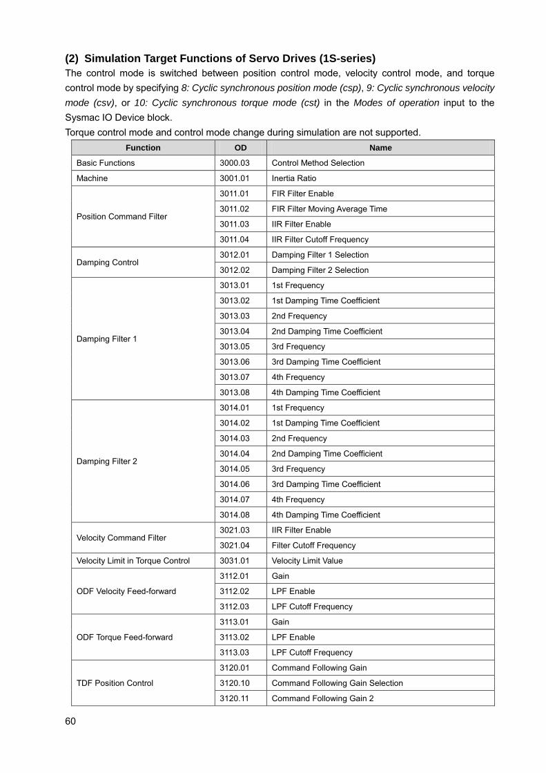
(2) Simulation Target Functions of Servo Drives (1S-series) The control mode is switched between position control mode, velocity control mode, and torque control mode by specifying 8: Cyclic synchronous position mode (csp), 9: Cyclic synchronous velocity mode (csv), or 10: Cyclic synchronous torque mode (cst) in the Modes of operation input to the Sysmac IO Device block. Torque control mode and control mode change during simulation are not supported.
Function OD Name
Basic Functions 3000.03 Control Method Selection
Machine 3001.01 Inertia Ratio
Position Command Filter
3011.01 FIR Filter Enable
3011.02 FIR Filter Moving Average Time
3011.03 IIR Filter Enable
3011.04 IIR Filter Cutoff Frequency
Damping Control 3012.01 Damping Filter 1 Selection
3012.02 Damping Filter 2 Selection
Damping Filter 1
3013.01 1st Frequency
3013.02 1st Damping Time Coefficient
3013.03 2nd Frequency
3013.04 2nd Damping Time Coefficient
3013.05 3rd Frequency
3013.06 3rd Damping Time Coefficient
3013.07 4th Frequency
3013.08 4th Damping Time Coefficient
Damping Filter 2
3014.01 1st Frequency
3014.02 1st Damping Time Coefficient
3014.03 2nd Frequency
3014.04 2nd Damping Time Coefficient
3014.05 3rd Frequency
3014.06 3rd Damping Time Coefficient
3014.07 4th Frequency
3014.08 4th Damping Time Coefficient
Velocity Command Filter 3021.03 IIR Filter Enable
3021.04 Filter Cutoff Frequency
Velocity Limit in Torque Control 3031.01 Velocity Limit Value
ODF Velocity Feed-forward
3112.01 Gain
3112.02 LPF Enable
3112.03 LPF Cutoff Frequency
ODF Torque Feed-forward
3113.01 Gain
3113.02 LPF Enable
3113.03 LPF Cutoff Frequency
TDF Position Control
3120.01 Command Following Gain
3120.10 Command Following Gain Selection
3120.11 Command Following Gain 2
61
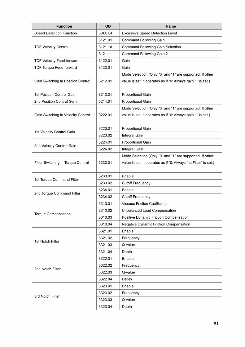
Function OD Name
Speed Detection Function 3B60.04 Excessive Speed Detection Level
TDF Velocity Control
3121.01 Command Following Gain
3121.10 Command Following Gain Selection
3121.11 Command Following Gain 2
TDF Velocity Feed-forward 3122.01 Gain
TDF Torque Feed-forward 3123.01 Gain
Gain Switching in Position Control 3212.01
Mode Selection (Only “0” and “1” are supported. If other
value is set, it operates as if “0: Always gain 1” is set.)
1st Position Control Gain 3213.01 Proportional Gain
2nd Position Control Gain 3214.01 Proportional Gain
Gain Switching in Velocity Control 3222.01
Mode Selection (Only “0” and “1” are supported. If other
value is set, it operates as if “0: Always gain 1” is set.)
1st Velocity Control Gain 3223.01 Proportional Gain
3223.02 Integral Gain
2nd Velocity Control Gain 3224.01 Proportional Gain
3224.02 Integral Gain
Filter Switching in Torque Control 3232.01
Mode Selection (Only “0” and “1” are supported. If other
value is set, it operates as if “0: Always 1st Filter” is set.)
1st Torque Command Filter 3233.01 Enable
3233.02 Cutoff Frequency
2nd Torque Command Filter 3234.01 Enable
3234.02 Cutoff Frequency
Torque Compensation
3310.01 Viscous Friction Coefficient
3310.02 Unbalanced Load Compensation
3310.03 Positive Dynamic Friction Compensation
3310.04 Negative Dynamic Friction Compensation
1st Notch Filter
3321.01 Enable
3321.02 Frequency
3321.03 Q-value
3321.04 Depth
2nd Notch Filter
3322.01 Enable
3322.02 Frequency
3322.03 Q-value
3322.04 Depth
3rd Notch Filter
3323.01 Enable
3323.02 Frequency
3323.03 Q-value
3323.04 Depth
62
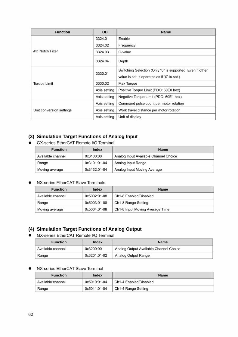
Function OD Name
4th Notch Filter
3324.01 Enable
3324.02 Frequency
3324.03 Q-value
3324.04 Depth
Torque Limit
3330.01 Switching Selection (Only “0” is supported. Even if other
value is set, it operates as if “0” is set.)
3330.02 Max Torque
Axis setting Positive Torque Limit (PDO: 60E0 hex)
Axis setting Negative Torque Limit (PDO: 60E1 hex)
Unit conversion settings
Axis setting Command pulse count per motor rotation
Axis setting Work travel distance per motor rotation
Axis setting Unit of display
(3) Simulation Target Functions of Analog Input GX-series EtherCAT Remote I/O Terminal
Function Index Name
Available channel 0x3100:00 Analog Input Available Channel Choice
Range 0x3101:01-04 Analog Input Range
Moving average 0x3132:01-04 Analog Input Moving Average
NX-series EtherCAT Slave Terminals
Function Index Name
Available channel 0x5002:01-08 Ch1-8 Enabled/Disabled
Range 0x5003:01-08 Ch1-8 Range Setting
Moving average 0x5004:01-08 Ch1-8 Input Moving Average Time
(4) Simulation Target Functions of Analog Output GX-series EtherCAT Remote I/O Terminal
Function Index Name
Available channel 0x3200:00 Analog Output Available Channel Choice
Range 0x3201:01-02 Analog Output Range
NX-series EtherCAT Slave Terminal
Function Index Name
Available channel 0x5010:01-04 Ch1-4 Enabled/Disabled
Range 0x5011:01-04 Ch1-4 Range Setting

MEMO

2016
0317(0613) W529-E1-05