ns-sw901 · 2019-01-24 · hold the port as it might cause personal injury and/or damage to this...
TRANSCRIPT

NS-SW901SUBWOOFER
RTKAL
OWNER’S MANUALMANUAL DE INSTRUCCIONES
使用说明书서용설명서

Thank you for selecting this Yamaha product.
Please read the following operating precautions before use. Yamaha will not be held responsible for any damage and/or injury caused by not following the cautions below.• To assure the finest performance, please read this manual
carefully. Keep it in a safe place for future reference.• Install this unit in a cool, dry, clean place - away from
windows, heat sources, sources of excessive vibration, dust, moisture and cold. Avoid sources of humming (transformers, motors). To prevent fire or electrical shock, do not expose this unit to rain or water.
• The voltage to be used must be the same as that specified on the rear panel. Using this unit with a higher voltage than specified is dangerous and may cause a fire and/or electric shock.
• Do not use force on switches, controls or connection wires. When moving the unit, first disconnect the power plug and the wires connected to other equipments. Never pull the wires themselves.
• When not planning to use this unit for a long period (ie., vacation, etc.), disconnect the AC power plug from the wall outlet.
• Since this unit has a built-in power amplifier, heat will radiate from the rear panel. Place the unit apart from the walls, allowing at least 20 cm of space above, behind and on both sides of the unit to prevent fire or damage. Furthermore, do not position with the rear panel facing down on the floor or other surfaces.
• Do not cover the rear panel of this unit with a newspaper, a tablecloth, a curtain, etc. in order not to obstruct heat radiation. If the temperature inside the unit rises, it may cause fire, damage to the unit and/or personal injury.
• Do not place the following objects on this unit:- Glass, china, small metallic etc.
If glass etc. falls by vibrations and breaks, it may cause bodily injury.
- A burning candle etc.If the candle falls by vibrations, it may cause fire and bodily injury.
- A vessel with water in it If the vessel falls by vibrations and water spills, it may cause damage to the speaker, and/or you may get an electric shock.
• Do not place this unit where foreign objects such as water drips might fall. It might cause a fire, damage to this unit, and/or personal injury.
• Never put a hand or a foreign object into the YST port located on the front side of this unit. When moving this unit, do not hold the port as it might cause personal injury and/or damage to this unit.
• Never place a fragile object near the YST port of this unit. If the object falls or drops by the air pressure, it may cause damage to the unit and/or personal injury.
• Never open the cabinet. It might cause an electric shock, since this unit uses a high voltage. It might also cause personal injury and/or damage to this unit. If something drops into the set, contact your dealer.
• When using a humidifier, be sure to avoid condensation inside this unit by allowing enough spaces around this unit or avoiding excess humidification. Condensation might cause a fire, damage to this unit, and/or electric shock.
• Super-bass frequencies reproduced by this unit may cause a turntable to generate a howling sound. In such a case, move this unit away from the turntable.
• This unit may be damaged if certain sounds are continuously output at high volume level. For example, if 20 Hz-50 Hz sine waves from a test disc, bass sounds from electronic instruments, etc. are continuously output, or when the stylus of a turntable touches the surface of a disc, reduce the volume level to prevent this unit from being damaged.
• If you hear distorted noise (i.e., unnatural, intermittent “rapping” or “hammering” sounds) coming from this unit, reduce the volume level. Extremely loud playing of a movie soundtrack’s low frequency, bass-heavy sounds or similarly loud popular music passages can damage this speaker system.
• Vibration generated by super-bass frequencies may distort images on a TV. In such a case, move this unit away from the TV set.
• Do not attempt to clean this unit with chemical solvents as this might damage the finish. Use a clean, dry cloth.
• Be sure to read the “TROUBLESHOOTING” section regarding common operating errors before concluding that the unit is faulty.
• Install this unit near the wall outlet and where the AC power plug can be reached easily.
• The batteries shall not be exposed to excessive heat such as sunshine, fire or the like. - Keep the batteries in a location out of reach of children.
Batteries can be dangerous if a child were to put in his or her mouth.
- If the batteries grow old, the effective operation range of the remote control decreases considerably. If this happens, replace the batteries with new one as soon as possible.
- Do not use old batteries together with new ones.- Do not use different types of batteries (such as alkalineand
manganese batteries) together. Read the packaging carefully as these different types of batteries may have the same shape and color.
- Exhausted batteries may leak. If the batteries have leaked, dispose of them immediately. Avoid touching the leaked material or letting it come into contact with clothing, etc. Clean the battery compartment thoroughly before installing new batteries.
- If you plan not to use the unit for a long period of time, remove the batteries from the unit. Otherwise, the batteries will wear out, possibly resulting in a leakage of battery liquid that may damage the unit.
- Do not throw away batteries with general house waste. Dispose of them correctly in accordance with your local regulations.
• Secure placement or installation is the owner’s responsibility. Yamaha shall not be liable for any accident caused by improper placement or installation of speakers.
CAUTION: Read this before operating your unit.
CAUTIONDanger of explosion if battery is incorrectly replaced. Replace only with the same or equivalent type.
WARNINGTO REDUCE THE RISK OF FIRE OR ELECTRIC SHOCK, DO NOT EXPOSE THIS APPLIANCE TO RAIN OR MOISTURE.
i En

En
glish
• VOLTAGE SELECTOR (Asia and General models only)The voltage selector switch on the rear panel of this unit must be set for your local main voltage BEFORE plugging this unit into the AC main supply. Voltages are 110/120/220/230-240 V AC, 50/60 Hz.
GETTING STARTED ............................................. 1Features ........................................................................ 1
About this manual ....................................................... 1
Supplied accessories................................................... 1
Controls and functions ................................................ 2
Preparing the remote control ...................................... 4
PLACEMENT ........................................................ 5Subwoofer orientation ................................................. 5
CONNECTIONS .................................................... 6 Connecting to the amplifier equipped
with subwoofer (line out) terminal(s) .......................... 6
Connecting to an amplifier not equipped with a subwoofer (line out) terminal.............................. 8
Connecting to the ground terminal........................... 11
Connecting the power cable...................................... 11
USING THIS UNIT ............................................... 12Adjusting the sound balance .................................... 12
Storing the sound balance settings.......................... 13
Setting the sleep timer ............................................... 13
Operating the power of this unit using the remote control of your amplifier......................... 14
Frequency response .................................................. 15
Advanced Yamaha Active Servo Technology II................................ 16
TROUBLESHOOTING ........................................ 17
SPECIFICATIONS .............................................. 18
This unit features a magnetically shielded design, but there is still a chance that placing it too close to a TV set might impair picture color. Should this happen, move this unit away from the TV set.
This unit is not disconnected from the AC power source as long as it is connected to the wall outlet, even if this unit itself is turned off. In this state, this unit is designed to consume a very small quantity of power.
Taking care of the speakerTo maintain the spotless glossy surface of the polished finish, wipe it with a soft, dry cloth. To avoid damage to the finish, do not apply chemical solvents, such as alcohol, benzine, thinner, insecticide, etc. Also, do not use a damp cloth, or any type of cloth that contains chemical solvents, or place a plastic or vinyl sheet on top of the speaker.Otherwise, the finish may peel, the color may fade, or the sheet may stick to the surface.
CONTENTS
1
2
ii En

3
◆ High 600 W dynamic power
◆ L.F.E input terminal
◆ Sleep timer
◆ Remote control capability You can make setting changes and adjustments for this unit by using the remote control from your listening position.
◆ Advanced Yamaha Active Servo Technology IIThis unit employs Advanced Yamaha Active Servo Technology II which Yamaha has developed for reproducing higher quality super-bass sound.
◆ Two input connectionsThis unit can be easily added to your existing audio system by connecting to either the speaker terminals or the line output (pin jack) terminals of the amplifier.
◆ Optimum bass sounds with various settingsSetting high cut and phase keeps the optimum sound quality balance between the front speakers and this unit.
◆ B.A.S.S. mode button This unit is equipped with the B.A.S.S. mode button so that you can enjoy bass sound that matches any kind of source.
• In this manual, operations that can be performed using either the front panel of this unit or the remote control are explained using the remote control.
• y indicates a tip for your operation.• Notes contain important information about safety and operating instructions.
Check that you have received all of the following parts.
GETTING STARTED
Features
About this manual
Supplied accessories
Power cable
POWER STANDBY SLEEP
PHASE
MEMORY
PRESET
HIGH CUT VOLUME
21 3
B.A.S.S.
Remote control
Batteries (2)(AA, R6, UM-3)
1 En
GETTING STARTED En
glish
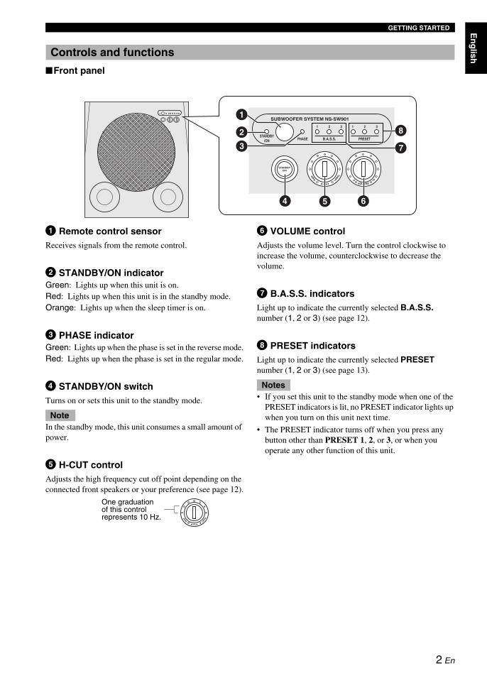
■Front panel
1 Remote control sensorReceives signals from the remote control.
2 STANDBY/ON indicatorGreen: Lights up when this unit is on.Red: Lights up when this unit is in the standby mode.Orange: Lights up when the sleep timer is on.
3 PHASE indicatorGreen: Lights up when the phase is set in the reverse mode.Red: Lights up when the phase is set in the regular mode.
4 STANDBY/ON switchTurns on or sets this unit to the standby mode.
In the standby mode, this unit consumes a small amount of power.
5 H-CUT controlAdjusts the high frequency cut off point depending on the connected front speakers or your preference (see page 12).
6 VOLUME controlAdjusts the volume level. Turn the control clockwise to increase the volume, counterclockwise to decrease the volume.
7 B.A.S.S. indicatorsLight up to indicate the currently selected B.A.S.S. number (1, 2 or 3) (see page 12).
8 PRESET indicatorsLight up to indicate the currently selected PRESET number (1, 2 or 3) (see page 13).
• If you set this unit to the standby mode when one of the PRESET indicators is lit, no PRESET indicator lights up when you turn on this unit next time.
• The PRESET indicator turns off when you press any button other than PRESET 1, 2, or 3, or when you operate any other function of this unit.
Controls and functions
H-CUT
SUBWOOFER SYSTEM NS-SW901
STANDBY/ON
STANDBY/ON PHASE
1 2 3 1 2 3
B.A.S.S. PRESET
140H
z40Hz
VOLUME100
1
23
4 5 6
7
8
Note
H-CUT
140H
z40Hz
One graduation of this control represents 10 Hz.
Notes
2 En

GETTING STARTED
■Rear panel
1 GND terminalSee page 11 for connection information.
2 INPUT 3 terminalsSee pages 6 - 7 for connection information.
3 INPUT 2 (LFE) terminalsSee page 7 for connection information.
4 OUTPUT terminalsSee page 9 for connection information.
5 INPUT 1 terminalsSee pages 9 - 10 for connection information.
6 AC INConnects the supplied power cable (see page 11).
7 POWER switchSwitches the power (ON/OFF) of this unit.Normally, set this switch to the ON position. When this unit is not used for a long period of time, set the switch to the OFF position.
■Remote control
1 STANDBYSets this unit to the standby mode.
In the standby mode, this unit consumes a small amount of power.
2 POWERTurns on this unit.
3 B.A.S.S.Selects a mode that is suitable for the source.Each time you press B.A.S.S., the B.A.S.S. indicator changes between 1, 2, and 3.
4 PRESETStores or recalls the B.A.S.S., volume, high-cut frequency and phase settings (see page 13).
5 HIGH CUT /Adjusts the high frequency cut off point depending on the connected front speakers or your preference (see page 12).
6 SLEEPSets the sleep timer (see page 13).
7 PHASESwitches the phase mode.Normally, set this unit to the reverse position. However, according to your speaker systems or the listening condition, there may be cases when better sound quality is obtained by setting this switch to the normal position. Select the better position by monitoring the sound.
8 MEMORYStores the B.A.S.S., volume, high-cut frequency and phase settings (see page 13).
9 VOLUME /Adjusts the volume of this unit.
OUTPUTTO SPEAKERS
FROM AMPLIFIER
INPUT3
INPUT 2
INPUT 1
LLL R
RR
LR
MONO
OUTPUTTO SPEAKERS
FROM AMPLIFIER
INPUT3
INPUT 2
INPUT 1
LLL R
RR
LR
MONO
POWER
ON
OFF
POWER
ON
OFF
1 23
5
6 7
Note
POWER STANDBY SLEEP
PHASE
MEMORY
PRESET
HIGH CUT VOLUME
21 3
B.A.S.S.
123
4
5 9
87
6
3 En

GETTING STARTED En
glish
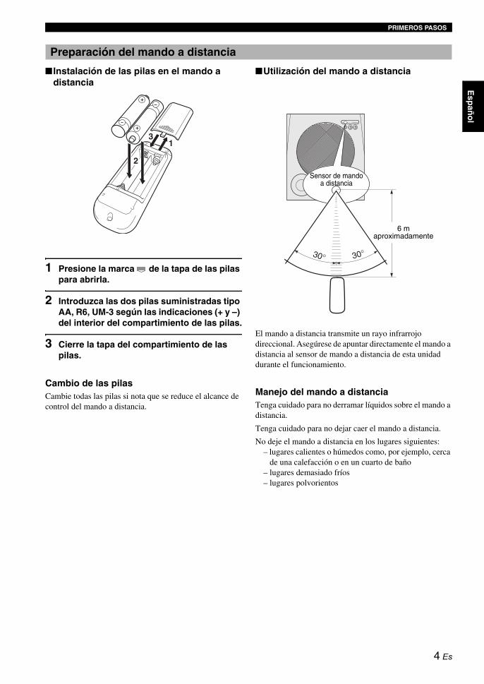
■ Installing the batteries in the remote control
1 Press the mark on the battery cover and open the cover.
2 Insert the two supplied type AA, R6, UM-3 batteries following the indications (+/–) inside the battery compartment.
3 Close the battery cover.
Replacing the batteriesChange all of the batteries if you notice conditions such as the operation range of the remote control decreases.
■Using the remote control
The remote control transmits a directional infrared ray. Be sure to aim the remote control directly at the remote control sensor on the main unit during operation.
Handling the remote control Be careful not to spill liquid on the remote control.
Be careful not to drop the remote control.
Do not leave the remote control in the following places:– hot or humid places, such as near a heater or in a
bathroom– extremely cold places– dusty places
Preparing the remote control
31
2
Remote control sensor
Approximately 6 m (20 ft)
4 En

Since the low-end frequencies of audio signals feature long wavelengths, they are almost non-directional to human ears. The super-bass range does not create a stereo image. Therefore, a single subwoofer may be enough to produce a high-quality super-bass sound. However, using two subwoofers (similarly to L and R front speakers) can enhance your acoustic experience.
Place the subwoofer as shown in fig. , or for the optimum effect.
: subwoofer : front speaker
Using one subwooferPlace the subwoofer on the outside of either the left or right front speaker.
Placing the subwoofer in between the left and right front speakersIf you are placing the subwoofer in between the left and right front speakers, position it slightly at an angle toward the wall for better effect.
Using two subwoofersPlace the subwoofers on the outside of each front speaker.
• This unit features a magnetically shielded design. However, there is still a chance that placing it too close to a CRT-type TV set might impair picture color. Should this happen, move this unit away from the TV set.
• If the speaker volume is very loud, furniture or window glass may resonate and the subwoofer itself may vibrate. In this case, lower the volume level. To limit resonance, use a thick curtain or similar cloth that tends to absorb sound vibrations effectively. Also, changing the subwoofer position may be helpful.
PLACEMENT
Subwoofer orientation
A B C
A
or
B
or
C
NoteThe placement shown in the figure below is also possible. However, if the subwoofer system is placed directly facing a wall, the bass effect may suffer due to phase cancellation caused by the interference between the direct and reflected sounds. To prevent this from happening, place the subwoofer system at an angle.
(Figures , , and ).A B C
There may be a case that you cannot obtain enough super-bass sound from the subwoofer due to standing waves.
Notes
5 En

En
glish
See pages 6 - 7 when your amplifier has subwoofer (line out) terminal(s), or see pages 8 - 10 when your amplifier has nosubwoofer (line out) terminal.
• Do not connect the power cord of this unit and other components into an AC outlet until all connections between components are completed.
• Be sure to connect the left channel (L), right channel (R), “+” (red) and “–” (black) properly. Also, refer to the owner’s manual of your component to be connected to this unit.
• The connection methods or the names of the terminals may differ depending on the component. Refer to the owner’s manual of your component as well.
When your amplifier has a one-channel subwoofer terminalConnect the subwoofer (or low pass etc.) terminal of your amplifier to the INPUT 3 ( /MONO) terminal of this unit using a commercially available mono pin cable.
When your amplifier has two-channel subwoofer terminals■Using one subwooferConnect the “L” side subwoofer terminal of your amplifier to the INPUT 3 ( /MONO) terminal of this unit and “R” side subwoofer terminal of your amplifier to the INPUT 3 ( ) terminal of this unit using a commercially available audio pin cable.
• Some amplifiers have line output terminals labeled PRE OUT. When you connect this unit to the PRE OUT terminals of the amplifier, make sure that the amplifier has at least two sets of PRE OUT terminals. If the amplifier has only one set of PRE OUT terminals, do not connect this unit to the PRE OUT terminals. Instead, connect this unit to the speaker terminals of the amplifier (see pages 8 - 9).
• When connecting to a monaural line output terminal of the amplifier, connect the INPUT 3 ( /MONO) terminal.• When connecting to line output terminals of the amplifier, other speakers should not be connected to the OUTPUT
terminals on the rear panel of this unit. If connected, they will not produce sound.
CONNECTIONS
Notes
Connecting to the amplifier equipped with subwoofer (line out) terminal(s)
Notes
1
L
OUTPUTTO SPEAKERS
FROM AMPLIFIER
LLL R
RR
LR
MONO
INPUT3
INPUT 2
INPUT 1
OUTPUTTO SPEAKERS
FROM AMPLIFIER
INPUT3
INPUT 2
INPUT 1
LLL R
RR
LR
MONO
POWER
ON
OFF
Amplifier
Mono pin cable (not included)
Subwoofer
LR
L
OUTPUTTO SPEAKERS
FROM AMPLIFIER
LLL R
RR
LR
MONO
INPUT3
INPUT 2
INPUT 1
OUTPUTTO SPEAKERS
FROM AMPLIFIER
INPUT3
INPUT 2
INPUT 1
LLL R
RR
LR
MONO
POWER
ON
OFF
Audio pin cable
(not included)
Amplifier
Subwoofer
6 En

CONNECTIONS
■Using two subwoofersConnect the “R” side subwoofer terminal of your amplifier to the INPUT 3 ( ) terminal on this unit using a commercially available mono pin cable, and connect the “L” side subwoofer terminal of your amplifier to the INPUT 3 ( /MONO) terminal of this unit using a commercially available mono pin cable.
■Connecting to an amplifier equipped with a high cut functionIf your amplifier can cut off high frequencies from signals sent to the subwoofer, connect the amplifier to the subwoofer’s INPUT2 (LFE) terminal(s). This will promote higher sound quality because the signal routing in the subwoofer is shortened by passing the built-in HIGH CUT circuit.
RL
POWER
ON
OFF
OUTPUTTO SPEAKERS
FROM AMPLIFIER
INPUT3
INPUT 2
INPUT 1
LLL R
RR
LR
MONOOUTPUT
TO SPEAKERS
FROM AMPLIFIER
INPUT3
INPUT 2
INPUT 1
LLL R
RR
LR
MONO
OUTPUTTO SPEAKERS
FROM AMPLIFIER
LLL R
RR
LR
MONO
OUTPUTTO SPEAKERS
FROM AMPLIFIER
LLL R
RR
LR
MONO
INPUT3
INPUT 2
INPUT 1
INPUT3
INPUT 2
INPUT 1
POWER
ON
OFF
Mono pin cable (not included)
AmplifierSubwooferSubwoofer
LL R
RR
R
MONO
INPUT3
INPUT 2
7 En

CONNECTIONS En
glish
Connect an amplifier (and front speakers) to this unit using commercially available speaker cables. Refer to the following instructions to make connections.
■Connecting to the speaker cable
1 Remove approximately 15 mm (5/8”) of insulation from each of the speaker cables.
2 Twist the exposed wires of the cable together to prevent short circuits.
3 Turn the knob counterclockwise to loosen.
4 Insert the bare wire into the hole in the side of each terminal.
5 Turn the knob clockwise to tighten.
6 Test the firmness of the connection by pulling gently on the cable at the terminal.
• Do not let the bare speaker wires touch each other, because this could damage this unit or the amplifier, or both of them.
• For connection, keep the speaker cables as short as possible. Do not bundle or roll up the excess part of the cables. If the connections are faulty, no sound will be heard from this unit or the speakers, or both of them.
• Make sure that the + and – polarity markings of the speaker terminals are observed and set correctly. If these cables are reversed, the sound will be unnatural and lack bass.
• Do not insert the insulation into the hole. The sound may not be produced.
■Banana plug connection
1 Tighten the knob.
2 Insert the banana plug connecter into the end of the corresponding terminal.
Connecting to an amplifier not equipped with a subwoofer (line out) terminal2
Notes
1 2
5
34
15 mm(5/8”) 1
2
8 En

CONNECTIONS
When your amplifier has one set of front speaker terminalsConnect the speaker terminals of the amplifier to the INPUT 1 terminals of this unit, and connect the OUTPUT terminals of this unit to the front speakers using a commercially available speaker cable.
y
Connecting front speakers via this unit does not affect the sound quality.
■Using one subwoofer
■Using two subwoofers
OUTPUTTO SPEAKERS
FROM AMPLIFIER
LLL R
RR
LR
MONO
INPUT3
INPUT 2
INPUT 1OUTPUT
TO SPEAKERS
FROM AMPLIFIER
INPUT3
INPUT 2
INPUT 1
LLL R
RR
LR
MONO
POWER
ON
OFF
Front speaker (R) Front speaker (L)
Speaker terminals
AmplifierSubwoofer
OUTPUTTO SPEAKERS
FROM AMPLIFIER
INPUT3
INPUT 2
INPUT 1
LLL R
RR
LR
MONO
OUTPUTTO SPEAKERS
FROM AMPLIFIER
INPUT3
INPUT 2
INPUT 1
LLL R
RR
LR
MONO
OUTPUTTO SPEAKERS
FROMAMPLIFIER
INPUT 3 INPUT 2
LLL R
RR
LR
MONO
OUTPUTTO SPEAKERS
FROM AMPLIFIER
LLL R
RR
LR
MONO
OUTPUTTO SPEAKERS
FROM AMPLIFIER
LLL R
RR
LR
MONO
INPUT3
INPUT 2
INPUT 1
INPUT3
INPUT 2
INPUT 1
POWER
ON
OFF
POWER
ON
OFF
Front speaker (R) Front speaker (L)
Speaker terminals
Subwoofer (R) Amplifier Subwoofer (L)
9 En
CONNECTIONS En
glish
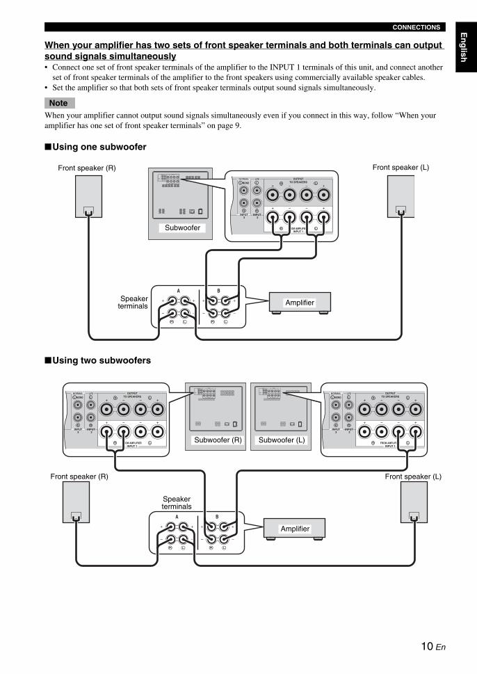
When your amplifier has two sets of front speaker terminals and both terminals can output sound signals simultaneously• Connect one set of front speaker terminals of the amplifier to the INPUT 1 terminals of this unit, and connect another
set of front speaker terminals of the amplifier to the front speakers using commercially available speaker cables.• Set the amplifier so that both sets of front speaker terminals output sound signals simultaneously.
When your amplifier cannot output sound signals simultaneously even if you connect in this way, follow “When your amplifier has one set of front speaker terminals” on page 9.
■Using one subwoofer
■Using two subwoofers
Note
OUTPUTTO SPEAKERS
FROM AMPLIFIER
LLL R
RR
LR
MONO
INPUT3
INPUT 2
INPUT 1
OUTPUTTO SPEAKERS
FROM AMPLIFIER
INPUT3
INPUT 2
INPUT 1
LLL R
RR
LR
MONO
POWER
ON
OFF
Front speaker (R) Front speaker (L)
Speakerterminals Amplifier
Subwoofer
OUTPUTTO SPEAKERS
FROM AMPLIFIER
LLL R
RR
LR
MONO
OUTPUTTO SPEAKERS
FROM AMPLIFIER
LLL R
RR
LR
MONO
INPUT3
INPUT 2
INPUT 1
INPUT3
INPUT 2
INPUT 1
OUTPUTTO SPEAKERS
FROM AMPLIFIER
INPUT3
INPUT 2
INPUT 1
LLL R
RR
LR
MONO
OUTPUTTO SPEAKERS
FROM AMPLIFIER
INPUT3
INPUT 2
INPUT 1
LLL R
RR
LR
MONO
POWER
ON
OFF
POWER
ON
OFF
Front speaker (R)
Speaker terminals
Front speaker (L)
Subwoofer (R) Subwoofer (L)
Amplifier
10 En
CONNECTIONS
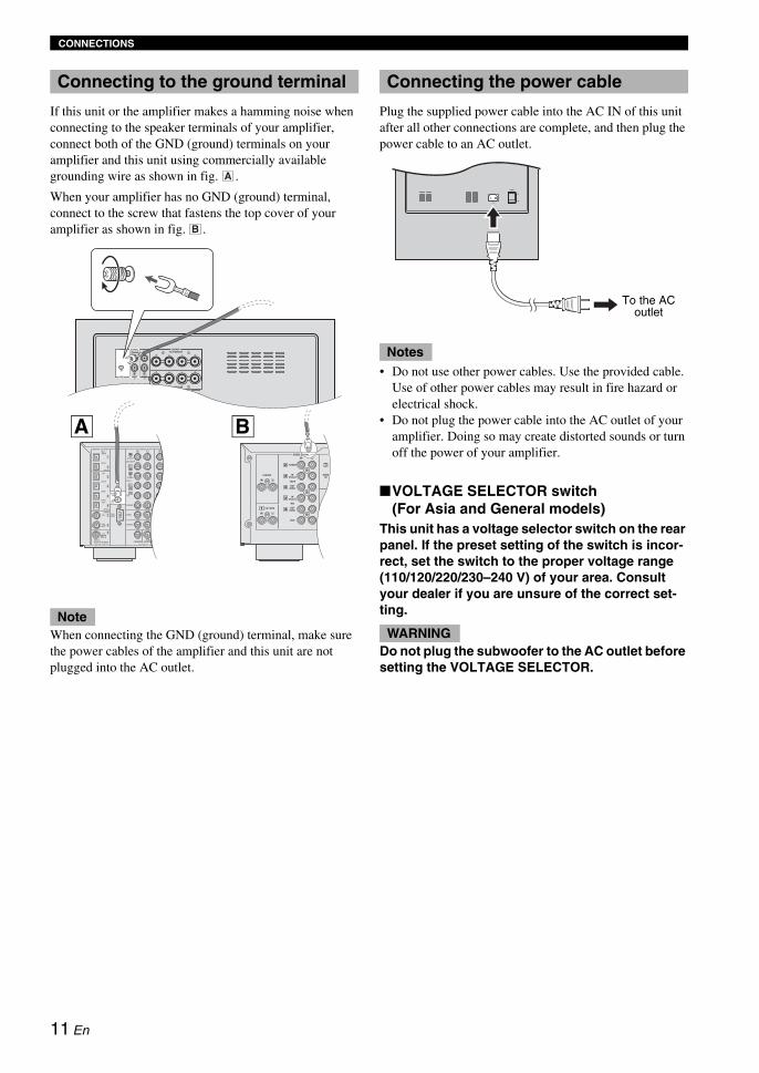
If this unit or the amplifier makes a hamming noise when connecting to the speaker terminals of your amplifier, connect both of the GND (ground) terminals on your amplifier and this unit using commercially available grounding wire as shown in fig. .
When your amplifier has no GND (ground) terminal, connect to the screw that fastens the top cover of your amplifier as shown in fig. .
When connecting the GND (ground) terminal, make sure the power cables of the amplifier and this unit are not plugged into the AC outlet.
Plug the supplied power cable into the AC IN of this unit after all other connections are complete, and then plug the power cable to an AC outlet.
• Do not use other power cables. Use the provided cable. Use of other power cables may result in fire hazard or electrical shock.
• Do not plug the power cable into the AC outlet of your amplifier. Doing so may create distorted sounds or turn off the power of your amplifier.
■VOLTAGE SELECTOR switch(For Asia and General models)
This unit has a voltage selector switch on the rear panel. If the preset setting of the switch is incor-rect, set the switch to the proper voltage range (110/120/220/230–240 V) of your area. Consult your dealer if you are unsure of the correct set-ting.
Do not plug the subwoofer to the AC outlet before setting the VOLTAGE SELECTOR.
Connecting to the ground terminal
Note
A
B
OUTPUTTO SPEAKERS
FROM AMPLIFIERINPUT 1
LLL R
RR
LR
MONO
INPUT3
INPUT 2
A B
Connecting the power cable
Notes
WARNING
POWER
ON
OFF
To the AC outlet
11 En

En
glish
Before using this unit, adjust the volume balance of this unit to obtain the optimum volume and tone balance between the front speakers and this unit by following the procedures below.
1 Set POWER switch on the rear panel of this unit to the ON position, and then press POWER to turn on this unit.The STANDBY/ON indicator lights up green.
2 Press VOLUME to set the volume level of this unit to the minimum (0).
3 Turn on the power of all other components.
4 Play back a source containing low-frequency components and adjust the volume level of your amplifier to the desired listening level.Set the tone control on your amplifier to the center position.
5 Press HIGH CUT / to adjust to the position where the desired response can be obtained.Normally, set the position to a level slightly higher than the minimum frequency of the front speaker.* To find out the minimum frequency of the front
speaker, refer to the owner’s manual of the front speaker.
6 Press VOLUME to increase the volume gradually to adjust the volume balance between the front speaker and this unit.Normally, set the volume to a level where you can obtain a little more bass effect than when this unit is not used.yIf you cannot obtain the desired response, repeat steps 5 and 6.
7 Press PHASE to select the regular or reverse mode.Normally, set it to the reverse mode. If you cannot obtain the desired response, set it to the regular mode.
8 Press B.A.S.S. to select a mode that is suitable for the source.1: WIDEWhen a movie source is played, the low- frequency effects are enhanced so that you can enjoy more powerful sound.
2: NORMALWhen a music or movie etc. source is played, you can enjoy natural bass sounds.
3: NARROWWhen an ordinary music source is played, the excessive low-frequency signals are cut off to make the sound clearer.
USING THIS UNIT
Adjusting the sound balance
POWER
ON
OFF
POWER
ON
OFF
POWER STANDBY SLEEP
PHASE
MEMORY
PRESET
HIGH CUT VOLUME
21 3
B.A.S.S.
1
2,6 1
Remote control Rear panel
SUBW
STANDBY/ON
PHASE switchIn most situations, set this switch to select the reverse mode. However, depending on your speaker systems or listening condition, there may be a case when bet-ter sound quality is obtained by selecting the regular mode. Select the better mode by monitoring the sound.
12 En

USING THIS UNIT
You can store up to 3 sets of your favorite settings (volume, high-cut, phase and B.A.S.S. setting) in this unit.
■Storing the settingIn the following procedure, PRESET 1 is used as an example.
1 Adjust the sound balance between the volume, high cut, phase and B.A.S.S. (see page 12).
2 Press MEMORY.The PRESET indicators on the front panel flash.
3 Press PRESET 1.The PRESET 1 indicator lights up. The current setting is stored as PRESET 1.
y• In step 3, pressing a stored number overwrites the old
setting.• While the VOLUME control or the H-CUT control is
rotating by pressing a PRESET, pressing another PRESET is ineffective.
■Recalling a settingPress PRESET you want to recall (1, 2 or 3).
■Memory back-upEven if you turn off this unit by using the POWER switch on the rear panel, this unit recalls the last setting when the power is turned back on (Last memory function).
If the power is cut for more than one week, the setting is cleared.
If you set the sleep timer, this unit automatically turns to the standby mode after 120 minutes.
Press SLEEP.
The color of the STANDBY/ON indicator changes to orange.
Pressing SLEEP again cancels the sleep timer.
Storing the sound balance settings
POWER STANDBY SLEEP
PHASE
MEMORY
PRESET
HIGH CUT VOLUME
21 3
B.A.S.S.
H-CUT
SUBWOOFER SYSTEM NS-SW901
STANDBY/ON
STANDBY/ON PHASE
1 2 3 1 2 3
B.A.S.S. PRESET
100H
z40Hz
VOLUME100
1 1
1
2
113
Remote control Front panel
STANDBY/ON indicator
-SW901
3 1 2 3
PRESET
Note
Setting the sleep timer
POWER STANDBY SLEEP
PHASE
MEMORY
PRESET
HIGH CUT VOLUME
21 3
B.A.S.S.
SLEEP
SUBW
STANDBY/ON
13 En

USING THIS UNIT En
glish
* This function is available only for Yamaha amplifiers that meet the following conditions: – The amplifier was released in 2005 or later. – The remote control of the amplifier has two different
buttons for STANDBY and ON.
When the AMP ID library code of the remote control has been changed, this function may not work.
■Setting
1 Set POWER switch on the rear panel to the OFF position.
2 Set POWER switch to the ON position while pressing and holding STANDBY/ON switch on the front panel. Continue holding down STANDBY/ON switch for 3 seconds or longer.
After the STANDBY/ON indicator flashes 4 times, the setting is completed.
■Canceling
1 Set POWER switch on the rear panel to the OFF position.
2 Set POWER switch to the ON position while pressing and holding STANDBY/ON switch on the front panel. Continue holding down STANDBY/ON switch for 3 seconds or longer.
After the STANDBY/ON indicator flashes 2 times, the setting is completed.
Place this unit within the operating range of the remote control of the amplifier. If you place this unit far away from the amplifier, you may not be able to operate this unit with the remote control.
Operating the power of this unit using the remote control of your amplifier
Note
H-CUT
SUBWOOFER SYSTEM NS-SW901
STANDBY/ON
STANDBY/ON PHASE
1 2 3 1 2 3
B.A.S.S. PRESET
100H
z40Hz
VOLUME100
POWER
ON
OFF
POWER
ON
OFF
POWER switch STANDBY/ON switch
Rear panel Front panel
SUBW
STANDBY/ON
Note
SUBW
STANDBY/ON
14 En

USING THIS UNIT
Frequency response of this unit
The figures below show the optimum adjustment of each control and the frequency response when this subwoofer is combined with a typical front speaker system.
■EX.1 When combined with 10 cm (4") or 13 cm (5") acoustic suspension, 2-way system front speakers
If you are using NS-F901 speakers as front speakers, use the following example as a reference when adjusting settings.
■EX.2 When combined with 20 cm (8") or 25 cm (10") acoustic suspension, 2-way system front speakers
* These diagrams do not depict actual frequency response characteristics accurately.
Frequency response
reverse mode(Green)
reverse mode(Green)
20 50 100 200 500Hz40
50
60
70
80
90
dB
H-CUT 140 Hz
Frequency response graph*
H-CUT
140H
z40Hz
VOLUME100
(H-CUT) (VOLUME)
OOFER SYSTEM S
PHASE
1
(PHASE)
20 50 100 200 500Hz40
50
60
70
80
90
dB
NS-SW901 (H-CUT 60 - 70 Hz)
Front speaker
Frequency response graph*
H-CUT
140H
z40Hz
VOLUME100
(H-CUT) (VOLUME)
OOFER SYSTEM S
PHASE
1
(PHASE)
20 50 100 200 500Hz40
50
60
70
80
90
dB
NS-SW901 (H-CUT 50 - 60Hz)
Front speaker
Frequency response graph*
15 En

En
glish
In 1988, Yamaha brought to the speaker systems utilizingYST (Yamaha Active Servo Technology) to give powerful, high quality bass reproduction. This technology uses a direct connection between the amplifier and speaker, allowing accurate signal transmission and precise speaker control.
As this technology uses speaker units controlled by the negative impedance drive of the amplifier and resonance generated between the cabinet capacity volume and port, it creates more resonant energy (the “air woofer” concept) than the standard bass reflex method. This allows for bass reproduction from much smaller cabinets than was previously possible.
Yamaha’s newly developed Advanced YST II adds many refinements to Yamaha Active Servo Technology, allowing better control of the forces driving the amplifier and speaker. From the amplifier’s point of view, the speaker impedance changes depending on the sound frequency. Yamaha developed a new circuit design combining negative-impedance and constant-current drives, which provides a more stable performance and clear bass reproduction without any murkiness.
Advanced Yamaha Active Servo Technology II
High-amplitude bass sound
Port
Cabinet
Advanced impedance Converter
Active Servo
Processing Amplifier
Signals of low amplitude
Air woofer (Helmholtz resonator)
Signals
16 En

Refer to the chart below when this unit does not function properly. If the problem you are experiencing is not listed below or if the instructions given below do not help, disconnect the power cord and contact your authorized Yamaha dealer or service center.
• When an excessive level of signal is input to this unit for 5 to 15 minutes, the POWER indicator starts flashing to alarm you of the danger of damaging the power amplifier and speaker of this unit. If the signal input lasts for 5 minutes more, this unit turns into the standby mode automatically.
• When an enormous amount of signal is input, the power of this unit is turned off immediately. To turn on this unit again, press STANDBY/ON switch on the front panel.
TROUBLESHOOTING
Problem Cause Remedy
Power is not supplied even though the STANDBY/ON switch is pressed.
The power plug is not securely connected. Connect it securely.
The POWER switch is set to the OFF position.
Set the POWER switch to the ON position.
No sound. The volume is set to the minimum (0). Raise the volume.
Speaker cables are not connected securely. Connect them securely.
The signals from the amplifier are too low. Increase the volume of the amplifier or the component connected to the amplifier.
The signal from the subwoofer output terminal of the amplifier is not output.
Check the speaker mode setting on the amplifier.
Sound level is too low. Speaker cables are not connected correctly. Connect them correctly, that is L (left) to L, R (right) to R, “+” to “+” and “–” to “–”.
Setting of the phase is not proper. Set the phase to the other position.
A source sound with few bass frequencies is being played.
Play a source sound with bass frequencies.Set the H-CUT to a higher position.
It is influenced by standing waves. Relocate the subwoofer or change its positioning angle.
The remote control does not work.
Wrong distance or angle. Use the remote control within a maximum range of 6 m and no more then 30 degrees off-axis from the front panel.
Direct sunlight or lighting from an inverter type of fluorescent lamp etc. is striking the remote control sensor of this unit.
Reposition this unit.
The batteries are weak. Replace all batteries.
There are obstacles between the remote control signal receiver on the unit and the remote control.
Remove the obstacles.
This unit is not turned on with the remote control of the amplifier. (when setting “Operating the power of this unit using the remote control of your amplifier”)
Wrong distance or angle. Place this unit within the operating range of the remote control of the amplifier.
The household breaker goes off. This unit consumes much electricity when a high level signal is input to this unit.
Turn down the volume on the amplifier etc. connected to this unit or cut off the power of other unused equipment.
An object has fallen into the port. Do not try to remove the object. Attempting to remove the object may cause a malfunction.
Contact an authorized Yamaha dealer or service center.
Notes
17 En
En
glish
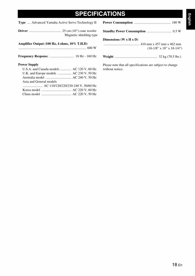
Type .... Advanced Yamaha Active Servo Technology IIDriver ...................................... 25 cm (10”) cone wooferMagnetic shielding type
Amplifier Output (100 Hz, 4 ohms, 10% T.H.D)............................................................................... 600 W
Frequency Response ............................. 18 Hz - 160 Hz
Power SupplyU.S.A. and Canada models ............. AC 120 V, 60 HzU.K. and Europe models ................ AC 230 V, 50 HzAustralia model .............................. AC 240 V, 50 HzAsia and General models....................... AC 110/120/220/230-240 V, 50/60 HzKorea model ................................... AC 220 V, 60 HzChina model ................................... AC 220 V, 50 Hz
Power Consumption ........................................... 180 W
Standby Power Consumption ............................. 0.5 W
Dimensions (W x H x D).......................................... 410 mm x 457 mm x 462 mm
(16-1/8” x 18” x 18-1/4”)
Weight .................................................. 32 kg (70.5 lbs.)
Please note that all specifications are subject to change without notice.
SPECIFICATIONS
18 En

Gracias por haber elegido este producto Yamaha.
Lea las siguientes precauciones de funcionamiento antes de iniciar el uso del aparato. Yamaha no se responsabilizará de cualquier daño y/o lesión causada por no seguir las precauciones que aparecen a continuación.• Lea cuidadosamente este manual para obtener el mejor
rendimiento posible. Manténgalo en un lugar seguro para utilizarlo como referencia en el futuro.
• Instale la unidad en un lugar fresco, seco y limpio, alejado de ventanas, aparatos que produzcan calor, lugares con muchas vibraciones, polvo, humedad o frío. Evite aparatos que causen ruidos de zumbido (transformadores y motores). Para evitar incendios o descargas eléctricas, no exponga el altavoz a la lluvia o al agua.
• El voltaje a utilizar debe de ser el mismo que el especificado en el panel trasero. La utilización de esta unidad con un voltaje superior al especificado puede causar un incendio y/o un a descarga eléctrica.
• No fuerce los interruptores, controles o cables de conexión. Cuando mueva esta unidad, desconecte primero el cable de alimentación y los cables conectados a otros equipos. No tire nunca de los cables en sí.
• Cuando no se va a usar el aparato por un largo tiempo (ej. vacaciones, etc.) desconecte el enchufe de alimentación de CA del tomacorriente.
• Este sistema irradia calor por el panel trasero debido a que tiene un amplificador de potencia incorporado. Coloque la unidad separada de las paredes, dejando unos 20 cm de espacio sobre, detrás y a ambos lados de la unidad para evitar un incendio o cualquier otro tipo de daño. Tampoco, se debe colocar con el panel trasero contra el piso o apoyado sobre otras superficies.
• No cubra el panel trasero de la unidad con papel de periódico, un mantel, una cortina, etc. para no obstruir la radiación de calor. Si aumenta la temperatura en el interior de la unidad, podrían originarse un incendio, daños a la unidad y/o lesiones personales.
• No coloque los siguientes objetos sobre esta unidad:- Vidrio, porcelanana, pequeños trozos de metal etc.
Si el vidrio, etc. se cae debido a las vibraciones y se romple, podría causar lesiones personales.
- Un candelabro encendido, etc.Si el candelabro cae debido a las vibraciones, podría provocar un incendio y lesiones personales.
- Un jarrón con agua en su interiorSi el jarrón cae debido a las vibraciones y el agua se derrama, podría causar daños en el altavoz, y/o una descarga eléctrica.
• No coloque esta unidad donde puedan caer objetos extraños, como agua derramada. Podría provocar un incendio, daños a esta unidad y/o daños personales.
• Nunca ponga las manos o un objeto extraño en el puerto YST, situado en la parte delantera de esta unidad. Al mover esta unidad, no sujete el puerto, ya que podría provocar lesiones personales y/o daños a esta unidad.
• Nunca coloque un objeto frágil cerca del puerto YST de esta unidad. Si el objeto cae o se vuelca debido a la presión del aire, podría provocar lesiones en la unidad y/o lesiones personales.
• No abra nunca la carcasa. Podría provocar una descarga eléctrica, ya que esta unidad es de alto voltaje. También podría provocar lesiones personales o averiar la unidad. Si algo cae en el equipo, póngase en contacto con su distribuidor.
• Cuando utilice un humidificador, asegúrese de evitar la condensación dentro esta unidad dejando suficiente espacio alrededor de esta unidad o evitando el exceso de humidificación. La condensación podría causar un incendio, daños a esta unidad, y/o descarga eléctrica.
• Las frecuencias de ultragraves generadas por esta unidad pueden hacer que el tocadiscos emita un sonido de aullidos. En este caso, alejar la unidad del tocadiscos.
• La unidad podría ser dañada, si se escucharan continuamente ciertos sonidos en el nivel máximo de volumen. Por ejemplo, si se escuchan ondas sinusoidales de 20 Hz-50 Hz con el disco de prueba, sonidos graves de instrumentos electrónicos, etc.; o cuando la aguja del tocadiscos toque la superficie de un disco, reduzca el nivel de volumen para evitar que se dañe el equipo.
• Si se escuchan sonidos distorsionados (ej. sonidos raros, “golpeteos” o “martilleos” intermitentes) provenientes de la unidad, baje el nivel del volumen. Si se reproducen con el volumen alto pistas de sonido de películas de baja frecuencia, sonidos con bajos fuertes o música de similares características se podría dañar el sistema de altavoces.
• La vibración generada por frecuencias ultragraves podría distorsionar las imágenes de una TV. En este caso, alejar el sistema del televisor.
• No intente limpiar esta unidad con disolventes químicos, ya que podrían dañar el acabado. Utilice para la limpieza un paño limpio y seco.
• No deje de leer la seeción “SOLUCIÓN DE PROBLEMAS”, donde se dan consejos sobre los errores de utilización antes de llegar a la conclusión de que la unidad está averiada.
• Instale esta unidad cerca de la toma de CA, donde se pueda llegar fácilmente a la clavija de alimentación de CA.
• Las baterías no deberán exponerse a un calor excesivo como, por ejemplo, el que producen los rayos del sol, el fuego y similares.- Mantenga las baterías en un lugar fuera del alcance de los
niños. Las baterías pueden ser peligrosas y los niños se las llevan a la boca.
- Si las pilas se agotan, el alcance operativo eficaz del mando a distancia se reduce considerablemente. Si esto sucediese, cambie las pilas por dos nuevas tan pronto como sea posible.
- No utilice pilas viejas y nuevas juntas.- No utilice juntas pilas de tipos diferentes (alcalinas de
manganeso, por ejemplo). Lea atentamente las instrucciones de la caja ya que hay distintos tipos de pilas con la misma forma y color.
- Las pilas gastadas pueden tener derrames. Si se produce algún derrame en las pilas, deséchelas inmediatamente. Evite tocar el líquido derramado o que entre en contacto con la ropa, etc. Ante de instalar pilas nuevas, limpie bien el compartimento de las pilas.
- Si no piensa utilizar la unidad durante un largo periodo de tiempo, extraiga las baterías de la unidad. De lo contrario, las baterías se gastarán y podrían filtrar líquido y dañar la unidad.
- No arroje las pilas al cubo de la basura. Deséchelas de acuerdo con la normativa local aplicables.
• La instalación en un lugar seguro es responsabilidad del propietario. Yamaha no se hace responsable por ningún accidente provocado por una instalación incorrecta de los altavoces.
PRECAUCIÓN: Leer este manual de instrucciones antes de poner la unidad en funcionamiento.
PRECAUCIÓNPeligro de explosión si la pila se sustituye incorrectamente. Sustitúyala por otra del mismo tipo o de un tipo equivalente.
ADVERTENCIAPARA REDUCIR EL RIESGO DE INCENDIOS Y DESCARGAS ELÉCTRICAS, NO EXPONGA ESTA UNIDAD A LA LLUVIA O A LA HUMEDAD.
i Es

Esp
año
l
• VOLTAGE SELECTOR (Modelos de Asia y generales)El interruptor de selección de tensión situado en el panel trasero de esta unidad debe ajustarse a la tensión principal de su emplazamiento ANTES de enchufar esta unidad a la corriente eléctrica. La selección de voltajes es para CA de 110/120/220/230-240 V, 50/60 Hz.
PRIMEROS PASOS .............................................. 1Características ....................................................... 1Acerca de este manual .......................................... 1Accesorios suministrados........................................... 1Controles y funciones ............................................ 2Preparación del mando a distancia ............................ 4
UBICACIÓN .......................................................... 5Orientación del subwoofer .......................................... 5
CONEXIONES ....................................................... 6 Conexión al amplificador equipado con
terminal(es) de altavoz de subgraves (salida de línea) ....................................................... 6
Conexión al amplificador no equipado con terminal de altavoz de subgraves (salida de línea) ....................................................... 8Conexión al terminal de tierra ............................. 11Conexión del cable de alimentación ................... 11
USO DE ESTA UNIDAD ..................................... 12Ajuste del balance del sonido ............................. 12Para guardar los ajustes del balance del sonido.... 13Preparación del temporizador para dormir ........ 13Control de la alimentación de esta unidad con el mando a distancia de su amplificador............ 14Características de frecuencia .............................. 15
Advanced Yamaha Active Servo Technology II ............................... 16
SOLUCIÓN DE PROBLEMAS ............................ 17
ESPECIFICACIONES ......................................... 18
Esta unidad dispone de un diseño a prueba de interferencias magnéticas, aunque existe la posibilidad de que, en el caso de colocarlo demasiado cerca de un aparato de TV, el color de la imagen pueda verse afectado. En este caso, aleje el sistema del televisor.
Esta unidad no se desconecta de la fuente de alimentación de CA si está conectada en una toma de CA, incluso si la propia unidad está apagada. En tal estado, la unidad está diseñada para consumir una cantidad de corriente muy pequeña.
Cuidados del altavozPara mantener impoluta la superficie satinada del acabado brillante, límpiela con un paño seco y suave. Para evitar dañar el acabado, no aplique disolventes químicos como el alcohol, bencina, disolventes, insecticidas, etc. No utilice tampoco un trapo húmedo o cualquier tipo de trapo que contenga disolventes químicos ni coloque una lámina de plástico o de vinilo encima del altavoz. Si lo hace, el acabado podría pelarse, el color desvanecerse o la lámina podría adherirse a la superficie.
CONTENIDO
1
2
ii Es

◆ Alta potencia dinámica de 600 W
◆ Terminal de entrada L.F.E
◆ Temporizador para dormir
◆ Capacidad para mando a distanciaUsando el mando a distancia desde su posición de escucha puede cambiar configuraciones y hacer ajustes para esta unidad.
◆ Advanced Yamaha Active Servo Technology IIEsta unidad emplea Advanced Yamaha Active Servo Technology II que Yamaha ha desarrollado para producir un sonido supergrave de calidad más alta.
◆ Dos conexiones de entrada.Esta unidad se puede incorporar fácilmente a su sistema de audio conectándola a los terminales de altavoces o a los terminales de salida de linea (jack de clavija) del amplificador.
◆ Sonidos graves óptimos con varios ajustesEl ajuste de fase y corte alto mantiene balances de sonido óptimos entre los altavoces delanteros y esta unidad.
◆ Botón de modo B.A.S.S.Esta unidad está equipada con el botón de modo B.A.S.S. para que usted pueda disfrutar de un sonido grave adecuado a cualquier fuente.
• En este manual, las operaciones que se pueden hacer usando el panel delantero de esta unidad y su mando a distancia se explican usando el mando a distancia.
• y indica un consejo para su utilización.• Las notas contienen información importante acerca de la seguridad y las instrucciones de funcionamiento.
Verifique que ha recibido todos los componentes siguientes.
PRIMEROS PASOS
Características
Acerca de este manual
Accesorios suministrados
Cable de alimentación
POWER STANDBY SLEEP
PHASE
MEMORY
PRESET
HIGH CUT VOLUME
21 3
B.A.S.S.
Mando a distancia
Pilas (2) (AA, R6, UM-3)
1 Es

PRIMEROS PASOS
Esp
año
l
■Panel delantero
1 Sensor de mando a distanciaRecibe señales del mando a distancia.
2 Indicador STANDBY/ONVerde: Se enciende cuando esta unidad está encendida.Rojo: Se enciende cuando esta unidad está en el modo de
espera.Anaranjado: Se enciende cuando el temporizador para
dormir está encendido.
3 Indicador PHASEVerde: Se enciende cuando la fase está en el modo de
inversión.Rojo: Se enciende cuando la fase está en el modo normal.
4 Conmutador STANDBY/ONEnciende esta unidad o la pone en el modo de espera.
En el modo de espera, esta unidad consume un poco de energía.
5 Control H-CUTAjusta el punto de corte de alta frecuencia según la combinación de altavoces delanteros de su preferencia (vea la página 12).
6 Control VOLUMEAjusta el nivel del sonido. Gire el control a la derecha para subir el volumen y a la izquierda para bajarlo.
7 Indicadores B.A.S.S.Se encienden para indicar el número B.A.S.S. (1, 2 o 3) actualmente seleccionado (vea la página 12).
8 Indicadores PRESETSe encienden para indicar el número PRESET (1, 2 o 3) actualmente seleccionado (vea la página 13).
• Si pone esta unidad en el modo de espera cuando está encendido uno de los indicadores PRESET, cuando encienda esta unidad la proxima vez no se encenderá ningún indicador PRESET.
• El indicador PRESET se apaga cuando se pulsa cualquier botón que no sea PRESET 1, 2 ó 3, o cuando usted utiliza cualquier otra función de esta unidad.
Controles y funciones
H-CUT
SUBWOOFER SYSTEM NS-SW901
STANDBY/ON
STANDBY/ON PHASE
1 2 3 1 2 3
B.A.S.S. PRESET
140H
z40Hz
VOLUME100
1
23
4 5 6
7
8
Nota
H-CUT
140H
z40Hz
Una graduación de este control representa 10 Hz.
Notas
2 Es

PRIMEROS PASOS
■Panel trasero
1 Terminal GNDVea la página 11 para conocer información de conexión.
2 Terminales INPUT 3Vea las páginas 6 - 7 para conocer información de conexión.
3 Terminales INPUT 2 (LFE)Vea la página 7 para conocer información de conexión.
4 Terminales OUTPUTVea las página 9 para conocer información de conexión.
5 Terminales INPUT 1Vea las páginas 9 - 10 para conocer información de conexión.
6 AC INConecta el cable de alimentación suministrado (vea la página 11).
7 Conmutador POWERConmuta la alimentación (ON/OFF) de esta unidad.Ponga normalmente este conmutador en la posición ON. Cuando esta unidad no se utilice durante mucho tiempo, ponga el conmutador en la posición OFF.
■Mando a distancia
1 STANDBY Pone esta unidad en el modo de espera.
En el modo de espera, esta unidad consume un poco de energía.
2 POWEREnciende esta unidad.
3 B.A.S.S.Selecciona un modo adecuado para la fuente.Cada vez que pulsa B.A.S.S., el indicador B.A.S.S. cambia entre 1, 2 y 3.
4 PRESETGuarda o recupera ajustes de B.A.S.S., volumen, frecuencia de corte alto y fase (vea la página 13).
5 HIGH CUT /Ajusta el punto de corte de alta frecuencia según la combinación de altavoces delanteros de su preferencia (vea la página 12).
6 SLEEPAjusta el temporizador para dormir (vea la página 13).
7 PHASECambia el modo de fase.Ponga normalmente este conmutador en la posición de inversión. Sin embargo, según su sistema de altavoces o condición de escucha, puede haber casos en los que se obtiene sonido de mejor calidad poniendo este conmutador en la posición normal. Seleccione la mejor posición comprobando el sonido.
8 MEMORYGuarda los ajustes de B.A.S.S., volumen, frecuencia de corte alto y fase (vea la página 13).
9 VOLUME /Ajusta el volumen de esta unidad.
OUTPUTTO SPEAKERS
FROM AMPLIFIER
INPUT3
INPUT 2
INPUT 1
LLL R
RR
LR
MONO
OUTPUTTO SPEAKERS
FROM AMPLIFIER
INPUT3
INPUT 2
INPUT 1
LLL R
RR
LR
MONO
POWER
ON
OFF
POWER
ON
OFF
1 23
5
6 7
Nota
POWER STANDBY SLEEP
PHASE
MEMORY
PRESET
HIGH CUT VOLUME
21 3
B.A.S.S.
123
4
5 9
87
6
3 Es
PRIMEROS PASOS
Esp
año
l
■ Instalación de las pilas en el mando a distancia
1 Presione la marca de la tapa de las pilas para abrirla.
2 Introduzca las dos pilas suministradas tipo AA, R6, UM-3 según las indicaciones (+ y –) del interior del compartimiento de las pilas.
3 Cierre la tapa del compartimiento de las pilas.
Cambio de las pilasCambie todas las pilas si nota que se reduce el alcance de control del mando a distancia.
■Utilización del mando a distancia
El mando a distancia transmite un rayo infrarrojo direccional. Asegúrese de apuntar directamente el mando a distancia al sensor de mando a distancia de esta unidad durante el funcionamiento.
Manejo del mando a distanciaTenga cuidado para no derramar líquidos sobre el mando a distancia.
Tenga cuidado para no dejar caer el mando a distancia.
No deje el mando a distancia en los lugares siguientes:– lugares calientes o húmedos como, por ejemplo, cerca
de una calefacción o en un cuarto de baño– lugares demasiado fríos– lugares polvorientos
Preparación del mando a distancia
31
2
Sensor de mando a distancia
6 m aproximadamente
4 Es

Dado que las frecuencias más bajas de las señales de audio disponen de amplias longitudes de onda, son prácticamente no direccionales para el oído humano. La gama de ultragraves no crea una imagen estéreo. Por lo tanto, un único subwoofer puede ser suficiente para producir un sonido de ultragraves de alta calidad. Sin embargo, la utilización de dos subwoofers (parecido a los altavoces principales L y R) puede realzar su experiencia acústica.
Coloque el subwoofer como se muestra en la figura , o para conseguir el efecto óptimo.
: subwoofer : altavoz delantero
Utilización de un subwooferColoque el subwoofer en el exterior del altavoz derecho o izquierdo principal.
Colocación del subwoofer entre los altavoces principales izquierdo y derechoSI va a colocar el subwoofer entre los altavoces principales izquierdo y derecho, colóquelo ligeramente en ángulo hacia la pared para obtener un mejor efecto.
Utilización de dos subwoofersColóquelos en el exterior de ambos altavoces principales.
• Esta unidad cuenta con un diseño con protección magnética. No obstante, todavía existe la posibilidad de que su ubicación demasiado cerca de un televisor con tubo de rayos catódicos afecte al color de la imagen. En tal caso, aleje esta unidad del televisor.
• Si el volumen del altavoz es demasiado alto, los muebles o los cristales pueden resonar e incluso el propio subwoofer podría vibrar. En tal caso, baje el nivel del volumen. Para limitar la resonancia, utilice una cortina gruesa o un tejido similar que absorba con efectividad las vibraciones del sonido. Cambiar la ubicación del subwoofer también puede resultar útil.
UBICACIÓN
Orientación del subwoofer
A B C
A
o
B
o
C
NotaTambién se puede utilizar la colocación mostrada en la figura siguiente. Sin embargo, si el sistema del subwoofer se coloca orientado directamente hacia la pared, el efecto de los graves podría perderse debido a la cancelación de fase provocada por la interferencia entre los sonidos directos y reflejados. Para evitar que esto suceda, coloque el sistema del subwoofer en
ángulo. (Figuras , y ).A B C
Se puede dar el caso de que no se logren suficientes sonidos de ultragraves desde el subwoofer debido a las ondas estacionarias.
Notas
5 Es

Esp
año
l
Vea las páginas 6 - 7 cuando su amplificador tenga terminal(es) de altavoz de subgraves (salida de línea), o las páginas 8 - 10 cuando no lo tenga.
• No conecte el cable de alimentación de esta unidad y otros componentes a una toma de CA hasta completar todas las conexiones entre los componentes.
• Asegúrese de conectar correctamente el canal izquierdo (L), el canal derecho (R), “+” (rojo) y “–” (negro). Consulte también el manual del propietario de su componente que va a ser conectado a esta unidad.
• Los métodos de conexión o los nombres de los terminales pueden ser diferentes según el componente. Consulte también el manual del propietario del componente.
Cuando su amplificador tiene un terminal de altavoz de subgravesConecte el terminal de altavoz de subgraves (o pasabajos, etc.) de su amplificador al terminal INPUT 3 ( /MONO) de esta unidad con un cable con clavija mono de venta en el comercio.
Cuando su amplificador tiene dos terminales de altavoces de subgraves■Uso de un altavoz de subgravesConecte el terminal de altavoz de subgraves del lado “L” de su amplificador al terminal INPUT 3 ( /MONO) de esta unidad, y el terminal de altavoz de subgraves del lado “R” de su amplificador al terminal INPUT 3 ( ) de esta unidad con un cable con clavija de audio de venta en el comercio.
• Algunos amplificadores tienen terminales de salida de línea con la etiqueta PRE OUT. Cuando conecte esta unidad a los terminales PRE OUT del amplificador, asegúrese de que el amplificador tenga un mínimo de dos juegos de terminales PRE OUT. Si el amplificador sólo tiene un juego de terminales PRE OUT, no conecte esta unidad a los terminales PRE OUT. En cambio, conecte esta unidad a los terminales de altavoces del amplificador (vea las páginas 8 - 9).
• Cuando conecte a un terminal de salida de línea mono del amplificador, conecte el terminal INPUT 3 ( /MONO).• Cuando conecte a los terminales de salida de línea del amplificador no deberán conectarse otros altavoces a los
terminales OUTPUT del panel trasero de esta unidad. Si se conectan no se producirá sonido.
CONEXIONES
Notas
Conexión al amplificador equipado con terminal(es) de altavoz de subgraves (salida de línea)
Notas
1
L
OUTPUTTO SPEAKERS
FROM AMPLIFIER
LLL R
RR
LR
MONO
INPUT3
INPUT 2
INPUT 1
OUTPUTTO SPEAKERS
FROM AMPLIFIER
INPUT3
INPUT 2
INPUT 1
LLL R
RR
LR
MONO
POWER
ON
OFF
Amplificador
Cable con clavija mono (no incluido)
Altavoz de subgraves
LR
L
OUTPUTTO SPEAKERS
FROM AMPLIFIER
LLL R
RR
LR
MONO
INPUT3
INPUT 2
INPUT 1
OUTPUTTO SPEAKERS
FROM AMPLIFIER
INPUT3
INPUT 2
INPUT 1
LLL R
RR
LR
MONO
POWER
ON
OFF
Cable con clavija de audio
(no incluido)
Amplificador
Altavoz de subgraves
6 Es

CONEXIONES
■Uso de dos altavoces de subgravesConecte el terminal de altavoz de subgraves del lado “R” de su amplificador al terminal INPUT 3 ( ) de esta unidad usando un cable con clavija mono de venta en el comercio, y conecte el terminal de altavoz de subgraves del lado “L” de su amplificador al terminal INPUT 3 ( /MONO) de esta unidad con un cable con clavija mono de venta en el comercio.
■Conexión al amplificador equipado con función de corte altoSi el amplificador puede cortar las frecuencias altas de las señales enviadas al subwoofer, conecte el amplificador en los terminales INPUT2 (LFE) del subwoofer. Conseguirá una mejor calidad de sonido porque la ruta de la señal en el subwoofer se acortará al pasar por el circuito HIGH CUT incorporado.
R
L
POWER
ON
OFF
OUTPUTTO SPEAKERS
FROM AMPLIFIER
INPUT3
INPUT 2
INPUT 1
LLL R
RR
LR
MONOOUTPUT
TO SPEAKERS
FROM AMPLIFIER
INPUT3
INPUT 2
INPUT 1
LLL R
RR
LR
MONO
OUTPUTTO SPEAKERS
FROM AMPLIFIER
LLL R
RR
LR
MONO
OUTPUTTO SPEAKERS
FROM AMPLIFIER
LLL R
RR
LR
MONO
INPUT3
INPUT 2
INPUT 1
INPUT3
INPUT 2
INPUT 1
POWER
ON
OFF
Cable con clavija de mono(no incluido)
AmplificadorAltavoz de subgravesAltavoz de subgraves
LL R
RR
R
MONO
INPUT3
INPUT 2
7 Es

CONEXIONES
Esp
año
l
Conecte un amplificador (y altavoces delanteros) a esta unidad utilizando cables de altavoces de venta en el comercio. Consulte las instrucciones siguientes para hacer las conexiones.
■Conexión de cables de altavoz
1 Quite aproximadamente 15 mm de aislamiento de cada cable de altavoz.
2 Retuerza juntos los conductores expuestos del cable para evitar cotocircuitos.
3 Gire la perilla hacia la izquierda para aflojar.
4 Inserte un cable pelado en el agujero de cada terminal.
5 Gire la perilla hacia la derecha para apretar.
6 Pruebe la firmeza de la conexión tirando suavemente del cable en el terminal.
• No permita que los cables de altavoces pelados se toquen entre sí porque podría dañarse esta unidad o el amplificador, o ambos.
• Para hacer conexiones, mantenga lo cables de los altavoces lo más cortos posible. No ate ni enrolle el exceso de los cables. Si fallan las conexiones no se oirá sonido de esta unidad o de los altavoces, o de ambos.
• Asegúrese de que las conexiones a los terminales de altavoces de polaridad + y – estén bien hechas. Si se invierten los cables, el sonido no será natural y faltará sonido grave.
• No inserte el aislamiento en el agujero. Puede que no se produzca sonido.
■Conexión de clavija tipo banana
1 Apriete la perilla.
2 Inserte el conector de clavija tipo banana hasta el fondo del terminal correspondiente.
Conexión al amplificador no equipado con terminal de altavoz de subgraves (salida de línea)2
Notas
1 2
5
34
15 mm
12
8 Es
CONEXIONES
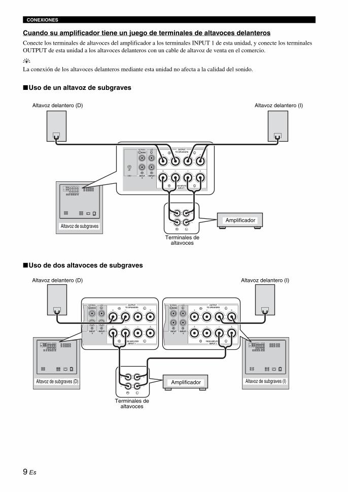
Cuando su amplificador tiene un juego de terminales de altavoces delanterosConecte los terminales de altavoces del amplificador a los terminales INPUT 1 de esta unidad, y conecte los terminales OUTPUT de esta unidad a los altavoces delanteros con un cable de altavoz de venta en el comercio.
y
La conexión de los altavoces delanteros mediante esta unidad no afecta a la calidad del sonido.
■Uso de un altavoz de subgraves
■Uso de dos altavoces de subgraves
OUTPUTTO SPEAKERS
FROM AMPLIFIER
LLL R
RR
LR
MONO
INPUT3
INPUT 2
INPUT 1OUTPUT
TO SPEAKERS
FROM AMPLIFIER
INPUT3
INPUT 2
INPUT 1
LLL R
RR
LR
MONO
POWER
ON
OFF
Altavoz delantero (D) Altavoz delantero (I)
Terminales de altavoces
AmplificadorAltavoz de subgraves
OUTPUTTO SPEAKERS
FROM AMPLIFIER
INPUT3
INPUT 2
INPUT 1
LLL R
RR
LR
MONO
OUTPUTTO SPEAKERS
FROM AMPLIFIER
INPUT3
INPUT 2
INPUT 1
LLL R
RR
LR
MONO
OUTPUTTO SPEAKERS
FROMAMPLIFIER
INPUT 3 INPUT 2
LLL R
RR
LR
MONO
OUTPUTTO SPEAKERS
FROM AMPLIFIER
LLL R
RR
LR
MONO
OUTPUTTO SPEAKERS
FROM AMPLIFIER
LLL R
RR
LR
MONO
INPUT3
INPUT 2
INPUT 1
INPUT3
INPUT 2
INPUT 1
POWER
ON
OFF
POWER
ON
OFF
Altavoz delantero (D) Altavoz delantero (I)
Terminales de altavoces
Altavoz de subgraves (D) Amplificador Altavoz de subgraves (I)
9 Es

CONEXIONES
Esp
año
l
Cuando su amplificador tiene dos juegos de terminales de altavoces delanteros y ambos terminales pueden dar salida simultáneamente a señales de sonido• Conecte un juego de terminales de altavoces delanteros del amplificador a los terminales INPUT 1 de esta unidad, y
conecte el otro juego de terminales de altavoces delanteros del amplificador a los altavoces delanteros usando cables de altavoces de venta en el comercio.
• Prepare el amplificador de forma que ambos juegos de terminales de altavoces delanteros den salida simultáneamente a las señales de sonido.
Cuando su amplificador no pueda dar salida simultáneamente a las señales de sonido aunque haga la conexión de esta forma, siga las indicaciones de “Cuando su amplificador tiene un juego de terminales de altavoces delanteros” en la página 9.
■Uso de un altavoz de subgraves
■Uso de dos altavoces de subgraves
Nota
OUTPUTTO SPEAKERS
FROM AMPLIFIER
LLL R
RR
LR
MONO
INPUT3
INPUT 2
INPUT 1
OUTPUTTO SPEAKERS
FROM AMPLIFIER
INPUT3
INPUT 2
INPUT 1
LLL R
RR
LR
MONO
POWER
ON
OFF
Altavoz delantero (D) Altavoz delantero (I)
Terminales dealtavoces Amplificador
Altavoz de subgraves
OUTPUTTO SPEAKERS
FROM AMPLIFIER
LLL R
RR
LR
MONO
OUTPUTTO SPEAKERS
FROM AMPLIFIER
LLL R
RR
LR
MONO
INPUT3
INPUT 2
INPUT 1
INPUT3
INPUT 2
INPUT 1
OUTPUTTO SPEAKERS
FROM AMPLIFIER
INPUT3
INPUT 2
INPUT 1
LLL R
RR
LR
MONO
OUTPUTTO SPEAKERS
FROM AMPLIFIER
INPUT3
INPUT 2
INPUT 1
LLL R
RR
LR
MONO
POWER
ON
OFF
POWER
ON
OFF
Altavoz delantero (D)
Terminales de altavoces
Altavoz delantero (I)
Altavoz de subgraves (D) Altavoz de subgraves (I)
Amplificador
10 Es

CONEXIONES
Si esta unidad o amplificador produce ruido de zumbido al conectarlo a los terminales de altavoces de su amplificador, conecte ambos terminales GND (tierra) de su amplificador y esta unidad usando un cable de puesta a tierrra de venta en el comercio como se muestra en la figura .
Cuando su amplificador no tenga terminal GND (tierra), conecte a un tornillo que sujete la cubierta superior de su amplificador, como se muestra en la figura .
Cuando conecte el terminal GND (tierra), asegúrese de que los cables de alimentación del amplificador y esta unidad no estén enchufados en la toma de CA.
Enchufe el cable de alimentación suministrado en AC IN de esta unidad después de terminar todas las demás conexiones, y luego enchufe el cable de alimentación en la toma de CA.
• No use otros cables de alimentación. Use el cable suministrado. Usar otros cables de alimentación puede causar un incendido o descarga eléctrica.
• No enchufe el cable de alimentación en la toma de CA de su amplificador. Esto puede distorsionar los sonidos o desconectar la alimentación de su amplificador.
■VOLTAGE SELECTOR (Selector de voltaje)(Para modelos de Asia y modelos generales)
Esta unidad cuenta con un selector de voltaje en el panel posterior. Si el ajuste prefijado del interruptor es incorrecto, adjuste el interruptor a la gama de voltaje correcta (110/120/220/230-240 V) de su región. Consulte con su distribuldor si no está seguro del adjuste correcto.
No conecte el subwoofer a la salida de CA sin antes ajustar el VOLTAGE SELECTOR.
Conexión al terminal de tierra
Nota
A
B
OUTPUTTO SPEAKERS
FROM AMPLIFIERINPUT 1
LLL R
RR
LR
MONO
INPUT3
INPUT 2
A B
Conexión del cable de alimentación
Notas
ADVERTENCIA
POWER
ON
OFF
A la toma de CA
11 Es

Esp
año
l
Antes de utilizar esta unidad, ajuste su balance de volumen, para obtener el balance de volumen y tono óptimo entre los altavoces delanteros y esta unidad, siguiendo los procedimientos descritos abajo.
1 Después de asegurarse de que el conmutador POWER del panel trasero de esta unidad esté en la posición ON, pulse POWER para encender esta unidad.El indicador STANDBY/ON se enciende en verde.
2 Pulse VOLUME para poner el nivel del sonido de esta unidad al mínimo (0).
3 Conecte la alimentación de todos los demás componentes.
4 Reproduzca una fuente que contenga componentes de baja frecuencia y ajuste el nivel del sonido de su amplificador como usted quiera.Ponga el control de tono de su amplificador en la posición central.
5 Pulse HIGH CUT / para ajustar la posición donde se va a obtener la respuesta deseada.Normalmente, elija una posición donde el nivel esté un poco por encima de la frecuencia mínima de los altavoces delanteros.* En cuanto a la frecuencia mínima de los altavoces
delanteros, consulte el manual del propietario de los mismos.
6 Pulse VOLUME para aumentar el volumen poco a poco y ajustar el balance del volumen entre los altavoces delanteros y esta unidad.Normalmente, ponga el nivel del sonido donde pueda obtener un poco más de efecto de graves que cuando no se usa esta unidad.yCuando no pueda obtener la respuesta deseada, repita los pasos 5 y 6.
7 Pulse PHASE para seleccionar el modo normal o de inversión.Póngalo normalmente en la posición de inversión. Si no puede obtener la respuesta deseada, póngalo en el modo normal.
8 Pulse B.A.S.S. para seleccionar un modo adecuado a la fuente.1: WIDECuando se reproduce una fuente tipo película, los efectos de baja frecuencia se realzan para disfrutar de un sonido más potente.
2: NORMALCuando se reproduce una fuente de música, película, etc., usted podrá disfrutar de sonidos graves naturales.
3: NARROWCuando se reproduce una fuente de música convencional, las señales de baja frecuencia excesiva se cortan para que el sonido sea más claro.
USO DE ESTA UNIDAD
Ajuste del balance del sonido
POWER
ON
OFF
POWER
ON
OFF
POWER STANDBY SLEEP
PHASE
MEMORY
PRESET
HIGH CUT VOLUME
21 3
B.A.S.S.
1
2,6 1
Mando a distancia Panel trasero
SUBW
STANDBY/ON
Interruptor PHASEEn la mayoría de las situaciones, configure este interruptor para seleccionar el modo inverso. Sin embargo, en función del sistema de altavoces o de las condiciones de escucha, puede darse el caso de que se obtenga una mejor calidad del sonido seleccionando el modo normal. Seleccione el modo más apropiado controlando el sonido.
12 Es

USO DE ESTA UNIDAD
En esta unidad puede guardar hasta 3 juegos de sus ajustes favoritos (volumen, corte alto, fase y ajuste B.A.S.S.).
■Para guardar los ajustesEn este procedimiento, usamos PRESET 1 como ejemplo.
1 Ajuste el balance del sonido entre el volumen, corte alto, fase y B.A.S.S. (vea la página 12).
2 Pulse MEMORY.El indicadores PRESET del panel delantero parpadearán.
3 Pulse PRESET 1.El indicador PRESET 1 se enciende. El ajuste actual se guarda como PRESET 1.
y• En el número 3, al pulsar el número guardado se borra el
ajuste anterior.• Mientras el control VOLUME o el control H-CUT está
girando pulsando PRESET, pulsar otro PRESET no sirve de nada.
■Recuperación de un ajustePulse el PRESET (1, 2 o 3) que usted quiera recuperar.
■Apoyo a la memoriaAunque usted apague esta unidad con el interruptor POWER del panel trasero, ésta recuperará el último ajuste cuando vuelva a encenderla (memoria del último ajuste).
El ajuste se borra si se corta la alimentación durante más de una semana.
Si prepara el temporizador para dormir, esta unidad se pondrá automáticamente en el modo de espera después de pasar 120 minutos.
Pulse SLEEP.
El color del indicador STANDBY/ON cambia a naranja.
Al pulsar de nuevo SLEEP se cancela el temporizador para dormir.
Para guardar los ajustes del balance del sonido
POWER STANDBY SLEEP
PHASE
MEMORY
PRESET
HIGH CUT VOLUME
21 3
B.A.S.S.
H-CUT
SUBWOOFER SYSTEM NS-SW901
STANDBY/ON
STANDBY/ON PHASE
1 2 3 1 2 3
B.A.S.S. PRESET
100H
z40Hz
VOLUME100
1 1
1
2
113
Mando a distancia Panel delantero
Indicador STANDBY/ON
-SW901
3 1 2 3
PRESET
Nota
Preparación del temporizador para dormir
POWER STANDBY SLEEP
PHASE
MEMORY
PRESET
HIGH CUT VOLUME
21 3
B.A.S.S.
SLEEP
SUBW
STANDBY/ON
13 Es

USO DE ESTA UNIDAD
Esp
año
l
* Esta función sólo se encuentra en los amplificadores Yamaha que satisfacen las condiciones siguientes: – El amplificador salió a la venta en 2005 o más
adelante. – El mando a distancia del amplificador tiene dos
botones diferentes para STANDBY y ON.
Esta función puede que no se active cuando el código de librería de identificación AMP del mando a distancia haya sido cambiado.
■Ajuste
1 Ponga el conmutador POWER del panel trasero en la posición OFF.
2 Ponga el conmutador POWER en la posición ON mientras mantiene pulsado el conmutador STANDBY/ON del panel delantero. Continúe pulsando el conmutador STANDBY/ON durante 3 segundos o más.
El ajuste termina después de parpadear 4 veces el indicador STANDBY/ON.
■Cancelación
1 Ponga el conmutador POWER del panel trasero en la posición OFF.
2 Ponga el conmutador POWER en la posición ON mientras mantiene pulsado el conmutador STANDBY/ON del panel delantero. Continúe pulsando el conmutador STANDBY/ON durante 3 segundos o más.
El ajuste termina después de parpadear 2 veces el indicador STANDBY/ON.
Ponga esta unidad dentro del alcance de control del mando a distancia del amplificador. Si pone esta unidad alejada del amplificador tal vez no pueda controlarla con el mando a distancia.
Control de la alimentación de esta unidad con el mando a distancia de su amplificador
Nota
H-CUT
SUBWOOFER SYSTEM NS-SW901
STANDBY/ON
STANDBY/ON PHASE
1 2 3 1 2 3
B.A.S.S. PRESET
100H
z40Hz
VOLUME100
POWER
ON
OFF
POWER
ON
OFF
Conmutador POWER Conmutador STANDBY/ON
Panel trasero Panel delantero
SUBW
STANDBY/ON
Nota
SUBW
STANDBY/ON
14 Es

USO DE ESTA UNIDAD
Características de frecuencia de esta unidad
Las figuras de abajo muestran el ajuste óptimo de cada control y las características de frecuencia cuando este altavoz de subgraves se combina con un sistema típico de altavoces delanteros.
■EJ.1 Cuando se usa en combinación con un sistema de altavoces principales de 2 vías de suspensión acústica de 10 cm o 13 cm.
Si está usando los altavoces NS-F901 como altavoces delanteros, use el ejemplo siguiente como referencia cuando ajuste las configuraciones.
■EJ.2 Cuando se usa en combinación con un sistema de altavoces principales de 2 vías de suspensión acústica de 20 cm o 25 cm.
* Este diagrama no muestra con precisión las características de respuesta de frecuencia reales.
Características de frecuencia
modo de inversión (Verde)
modo de inversión (Verde)
20 50 100 200 500Hz40
50
60
70
80
90
dB
H-CUT 140 Hz
Gráfico de respuestas de frecuencia*
H-CUT
140H
z40Hz
VOLUME100
(H-CUT) (VOLUME)
OOFER SYSTEM S
PHASE
1
(PHASE)
20 50 100 200 500Hz40
50
60
70
80
90
dB
NS-SW901 (H-CUT 60 - 70 Hz)
Altavoz delantero
Gráfico de respuestas de frecuencia*
H-CUT
140H
z40Hz
VOLUME100
(H-CUT) (VOLUME)
OOFER SYSTEM S
PHASE
1
(PHASE)
20 50 100 200 500Hz40
50
60
70
80
90
dB
NS-SW901 (H-CUT 50 - 60Hz)
Altavoz delantero
Gráfico de respuestas de frecuencia*
15 Es
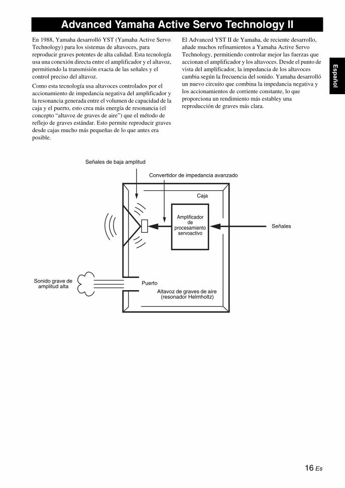
Esp
año
l
En 1988, Yamaha desarrolló YST (Yamaha Active Servo Technology) para los sistemas de altavoces, para reproducir graves potentes de alta calidad. Esta tecnología usa una conexión directa entre el amplificador y el altavoz, permitiendo la transmisión exacta de las señales y el control preciso del altavoz.
Como esta tecnología usa altavoces controlados por el accionamiento de impedancia negativa del amplificador y la resonancia generada entre el volumen de capacidad de la caja y el puerto, esto crea más energía de resonancia (el concepto “altavoz de graves de aire”) que el método de reflejo de graves estándar. Esto permite reproducir graves desde cajas mucho más pequeñas de lo que antes era posible.
El Advanced YST II de Yamaha, de reciente desarrollo, añade muchos refinamientos a Yamaha Active Servo Technology, permitiendo controlar mejor las fuerzas que accionan el amplificador y los altavoces. Desde el punto de vista del amplificador, la impedancia de los altavoces cambia según la frecuencia del sonido. Yamaha desarrolló un nuevo circuito que combina la impedancia negativa y los accionamientos de corriente constante, lo que proporciona un rendimiento más establey una reproducción de graves más clara.
Advanced Yamaha Active Servo Technology II
Sonido grave de amplitud alta
Puerto
Caja
Convertidor de impedancia avanzado
Amplificador de
procesamiento servoactivo
Señales de baja amplitud
Altavoz de graves de aire (resonador Helmholtz)
Señales
16 Es

Consulte el gráfico de abajo cuando esta unidad no funcione correctamente. Si el problema que usted tiene no está en la lista de abajo o las instrucciones dadas no ayudan, desconecte el cable de alimentación y póngase en contacto con su centro de servicio o concesionario Yamaha autorizado.
SOLUCIÓN DE PROBLEMAS
Problema Causa Remedio
No se suministra alimentación aunque se pulse el interruptor STANDBY/ON.
La clavija de alimentación no está bien conectada.
Conéctelos bien.
El conmutador POWER está en la posición OFF.
Ponga el interruptor POWER en la posición ON.
No hay sonido. El volumen está al mínimo (0). Suba el volumen.
Los cables de altavoces no están bien conectados.
Conéctelos bien.
Las señales del amplificador son demasiado pequeñas.
Suba el volumen del amplificador o del componente conectado al amplificador.
No sale la señal del terminal de salida de altavoz de subgraves del amplificador.
Asegúrese del ajuste del modo de los altavoces en el amplificador.
El nivel del sonido está demasiado bajo.
Los cables de altavoces no están bien conectados.
Conéctelos correctamente, es decir L (izquierda) a L, R (derecha) a R, “+” a “+” y “–” a “–”.
El ajuste de fase no es adecuado. Ajuste la fase en la otra posición .
Se reproduce una fuente con pocas frecuencias de graves.
Reproduzca una fuente con frecuencias de graves.Ponga H-CUT en una posición más alta.
Recibe influencia de ondas estacionarias. Vuelva a situar el subwoofer o cambie el ángulo de colocación.
El mando a distancia no funciona. Distancia o ángulo equivocados. Use el mando a distancia dentro de una distancia máxima de 6 m y sin exceder un ángulo de 30 grados a partir del eje central del panel delantero.
La luz solar directa o de otras luces (lámpara fluorescente tipo inversor, etc.) cae directamente sobre el sensor de mando a distancia de esta unidad.
Cambie la posición de esta unidad.
Las pilas están casi agotadas. Cambie todas las pilas.
Hay obstáculos entre el receptor de señales del mando a distancia de la unidad y el mando a distancia.
Elimine los obstáculos.
Esta unidad no se enciende con el mando a distancia del amplificador. (Cuando configura “Control de la alimentación de esta unidad con el mando a distancia de su amplificador”)
Distancia o ángulo equivocados. Ponga esta unidad dentro del alcance de control del mando a distancia del amplificador.
El disyuntor de casa se activa. Esta unidad consume mucha electricidad cuando se introduce en ella un señal de nivel alto.
Baje el volumen en el amplificador, etc. conectado a esta unidad o corte la alimentación a otros equipos que no se utilicen.
Un objeto ha caído dentro del puerto.
No intente extraer el objeto. Si intenta sacarlo puede provocar un funcionamiento incorrecto.
Póngase en contacto con un distribuidor o centro de servicio autorizado de Yamaha.
17 Es

Esp
año
l
• Cuando se introduce un nivel excesivo de señales en esta unidad durante 5 a 15 minutos, el indicador POWER empieza a parpadear para indicarle que existe el peligro de dañar el amplificador de potencia y el altavoz de esta unidad. Si la señal introducida dura 5 minutos o más, esta unidad se pone automáticamente en el modo de espera.
• Cuando se introduce una cantidad excesiva de señales, la alimentación de esta unidad se desconecta inmediatamente. Para encender de nuevo esta unidad, pulse el interruptor STANDBY/ON del panel delantero.
Tipo ..... Advanced Yamaha Active Servo Technology II
Bocina ........................ Altavoz de graves de cono 25 cmTipo blindado magnéticamente
Salida de amplificador (100 Hz, 4 ohmios, T.H.D de 10%)............................................................................... 600 W
Respuesta de frecuencia ....................... 18 Hz a 160 Hz
AlimentaciónModelos de EE.UU. y Canadá ........ CA 120 V, 60 HzModelos del R.U. y Europa ............ CA 230 V, 50 HzModelo de Australia ....................... CA 240 V, 50 HzModelos de Asia y General....................... CA 110/120/220/230-240 V, 50/60 HzModelo de Corea ............................ CA 220 V, 60 HzModelo de China ............................ CA 220 V, 50 Hz
Consumo .............................................................. 180 W
Consumo de alimentación en espera .................. 0,5 W
Dimensiones (An x Al x Prof).......................................... 410 mm x 457 mm x 462 mm
Peso ........................................................................ 32 kg
Note que todas las especificaciones están sujetas a cambios sin previo aviso.
Notas
ESPECIFICACIONES
18 Es

感谢您选用 Yamaha 超低音扬声器系统。
请在使用前阅读以下操作需知。对于不遵守以下操作需
知而造成的损坏和 /或伤害,Yamaha 概不负责。
• 为了确保获得最佳性能,请仔细阅读本使用说明书,并妥善保管,以备将来参考。
• 请在凉爽、干燥、清洁的地方安装本装置 - 应远离
窗口、热源,避免在振动过大、灰尘过多、湿气过
重和温度过低的地方使用。应远离嗡声源 (变压
器及马达)。为了避免火灾或电击的危险,请勿将
本装置暴露于雨水或湿气中。
• 使用的电压必须与后面板上标明的一致。如果使用
电压高于指定电压是危险的,可能会引起火灾和 /
或电击。
• 请勿在开关、控制器或连接线上强行施力。移动
时,应首先拔掉电源插头及连接其他设备的接线,
请勿拉动接线。
• 如果长期不使用本装置(如度假等),请从墙壁插
座中拔出交流电源插头。
• 因为本装置带有内置功率放大器,会通过后面板散
热。应将本装置远离墙壁放置。本装置的上方必须
留有至少 20 cm 的空间,背面和侧面保持充分的空
隙以避免火灾或损坏。另外,不得将后面板朝向地
板或其他表面放置。
• 请勿将报纸、桌布、窗帘等覆盖在本装置的后面板
上,不致于阻碍热量散发。如果装置内的温度升
高,将会导致火灾,破坏装置和或使人体受到伤
害。
• 请勿将以下物品放置在本装置上:
- 玻璃、陶瓷、小金属片等
如果玻璃等因振动而倒下和打碎,有可能使人体
受到伤害。
- 燃烧的蜡烛等
如果蜡烛因振动而倒下,有可能引起火灾和使人
体受到伤害。
- 装有水的容器
如果容器因振动而倒下或水溢出来,有可能使装
置受到损坏,并引起触电。
• 请勿将本装置放置在有异物例如水滴落下的地方,
否则可能导致火灾,破坏装置和 / 或使人体受到伤
害。
• 切勿将手或异物放进位于本机前部的 YST 舱门中。
当移动本机时,不可手抓舱门,否则可能导致人身
伤害和 / 或损坏本机。
• 切勿将易碎物体放在 YST 开门附近,如果物体因气
压而倒下或掉落,可能使装置受到破坏和 / 或使人
体受到伤害。
• 切勿开启箱体。因为本装置使用了高电压,有可能
造成电击。可能也会使人体受到伤害和 / 或破坏本
装置。如果异物落入本装置内,请与经销商联系。
• 使用加湿器时,要在本机附近留有足够的空间或不
要使湿度过大,以免机器内部结露。结露会造成火
灾,损坏本机和 / 或电击。
• 本装置复制的超低音频率可能使唱盘产生啸声,在
这种情况下,请将本装置远离唱盘放置。
• 如果某一声音以高音量持续输出,可能会损坏本装
置,例如,如果试碟产生 20 Hz 至 50 Hz 正弦波,
电子设备持续输出低音或可转动唱针接触到唱片表
面时,请降低音量,以防止本装置损坏。
• 如果从本装置中听到失真 (如不自然、间断的敲
击或击打声),请降低音量水平。电影声轨的低
频、超低音或类似的流行音乐播放音量过大,可能
会损坏此扬声器系统。
• 超低音频率产生的振动可能令电视机图像失真。在
此情况,请将本机搬离电视机。
• 请勿使用化学溶剂清洁本装置,否则有可能损坏抛
光面。请用清洁的干布擦拭。
• 遇到故障时,请阅读有关常见操作故障的 “故障
排除”一节。
• 将本机靠近电源插座安装以便电源的接插。
• 电池不能置于高热环境,比如火或直射日光等。
当您废弃电池时,请遵守当地的法律。
- 如果电池老化,遥控器的有效操作范围将显著缩
小。如果发生这样情况,请尽快更换新电池。
- 请将电池放在儿童无法拿到的地方。如果儿童将
电池放入嘴里,则可能有危险。
- 请勿混合使用新旧电池。
- 请勿混合使用不同类型的电池(如碱性电池和锌
锰电池)。请仔细查看电池包装,因为这些不同
类型的电池可能拥有相同的形状和颜色。
- 老化的电池可能会泄漏液体。如果电池已泄漏,
应立即进行处理。避免接触泄漏的材料或粘到衣
物上等。全面清理电池盒,然后再安装新电池。
- 如果计划在很长时间内不使用本机,请从本机取
出电池。否则电池将老化,从而可能因电池液体
泄漏而导致本机损坏。
- 请勿将电池与普通家庭垃圾一起丢弃。请按当地
的法律法规正确处理电池。
• 用户应自行负责安放或安装。若扬声器因安放或安
装不当而造成事故,Yamaha 公司概不负责。
注意事项:操作本装置前敬请阅读。
注意
如果电池更换不当可能会有爆炸的危险。只能更换
相同或相当类型的电池。
警告
为了减少火灾或电击的危险,切勿将本装置暴露于
雨水或湿气中。
虽然本机采用磁屏蔽设计,但若摆放位置与电视机
过于接近,则仍可能影响电视的画面色彩。在此情
况下,把本机搬离电视机。
i Zh

中文
• VOLTAGE SELECTOR (电压选择器)
(亚洲和通用型号 )
电压选择器位于本装置的后面板,把本装置插入交
流主电源前,必须把电压设定于适合当地的主电
压。
电压为 110/120/220/230-240 V AC, 50/60 Hz。
开始 ....................................... 1
特性 ...................................... 1
关于本说明书 .............................. 1
提供的配件................................. 1
控制按钮和功能............................. 2
准备遥控器................................. 4
摆放位置 ................................... 5
摆放位置................................... 5
连接 ....................................... 6
连接到具有超低音扬声器 (线输出)端子的放大器............................... 6
连接到没有装备有超低音扬声器 (线输出)端子的放大器............................... 8
连接到接地端子............................ 11
连接电源线................................ 11
使用本机 .................................. 12
调节音响平衡.............................. 12
保存音响平衡的设置........................ 13
设置睡眠定时器............................ 13
使用您的放大器的遥控器操作本机的电源...... 14
频率特性.................................. 15
Advanced Yamaha Active Servo Technology II ... 16
故障排除 .................................. 17规格 ...................................... 18
只要本装置仍然连接到墙壁插座,本装置即使已
经关闭也未与交流电源断开连接。此时本装置消
耗的电量很少。
爱护超低音扬声器
为了保持表面整洁光亮,请用干燥的软布擦拭。为
避免损坏表面涂层,请勿使用酒精、轻质汽油、稀
释剂、杀虫剂等化学溶剂。请勿使用湿布或任何含
化学溶剂的布匹类型,也不要将塑料或乙烯基布匹
放置覆盖在扬声器上。否则,可能发生表面涂层剥
落、颜色褪色或布匹粘住设备表面。
目录
1
2
ii Zh

◆ 600 W 高动态功率
◆ L.F.E 输入端子
◆ 睡眠定时器
◆ 遥控器功能
您可以从听音位置使用遥控器改变本机的设置或对
其进行调整。
◆ Advanced Yamaha Active Servo Technology II
本机使用 Advanced Yamaha Active Servo
Technology II,这是 Yamaha 开发的一种再现高质
量超低音音响的技术。
◆ 两种输入连接
通过连接放大器的扬声器端子或线输出(针形插
孔)端子的任何一方,您可以方便地将本机加入您
的现有的音频系统。
◆ 使用各种设置优化低音音响
设置高频截去和位相可以在前扬声器和本机之间保
持最佳的音响质量平衡。
◆ B.A.S.S. 模式按钮
本机装有 B.A.S.S. 模式按钮,使得您可以欣赏与
任何音源匹配的低音。
• 在本说明书中,对于可以同时使用本机的前面板和遥控器的操作,介绍使用遥控器的方法。
• y指示有关您的操作的提示。
• 注意事项中包含安全和操作说明的重要信息。
请检查您收到了下列所有的部件。
开始
特性
关于本说明书
提供的配件
电源线
遥控器
POWER STANDBY SLEEP
PHASE
MEMORY
PRESET
HIGH CUT VOLUME
21 3
B.A.S.S.
电池 (2)
(AA, R6, UM-3)
1 Zh
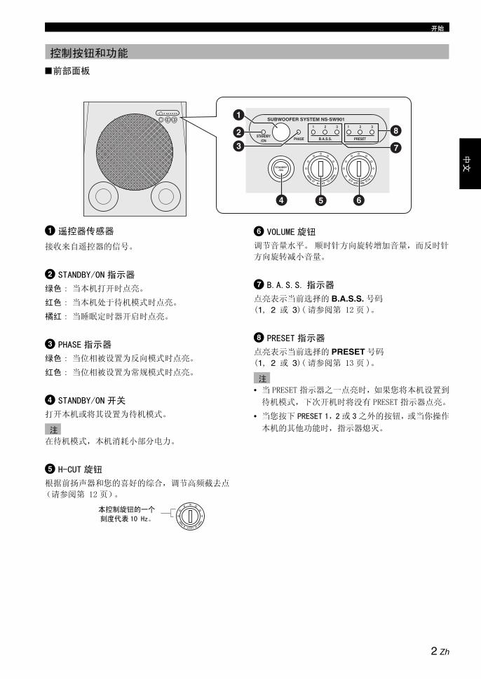
开始
中文
■前部面板
1 遥控器传感器
接收来自遥控器的信号。
2 STANDBY/ON 指示器
绿色 : 当本机打开时点亮。
红色 : 当本机处于待机模式时点亮。
橘红 : 当睡眠定时器开启时点亮。
3 PHASE 指示器
绿色 : 当位相被设置为反向模式时点亮。
红色 : 当位相被设置为常规模式时点亮。
4 STANDBY/ON 开关
打开本机或将其设置为待机模式。
在待机模式,本机消耗小部分电力。
5 H-CUT 旋钮
根据前扬声器和您的喜好的综合,调节高频截去点
(请参阅第 12 页)。
6 VOLUME 旋钮
调节音量水平。 顺时针方向旋转增加音量,而反时针
方向旋转减小音量。
7 B.A.S.S. 指示器
点亮表示当前选择的 B.A.S.S. 号码
(1, 2 或 3)( 请参阅第 12 页 )。
8 PRESET 指示器
点亮表示当前选择的 PRESET 号码
(1, 2 或 3)( 请参阅第 13 页 )。
• 当 PRESET 指示器之一点亮时,如果您将本机设置到
待机模式,下次开机时将没有 PRESET 指示器点亮。
• 当您按下 PRESET 1,2或 3之外的按钮,或当你操作
本机的其他功能时,指示器熄灭。
控制按钮和功能
H-CUT
SUBWOOFER SYSTEM NS-SW901
STANDBY/ON
STANDBY/ON PHASE
1 2 3 1 2 3
B.A.S.S. PRESET
140H
z40Hz
VOLUME100
1
23
4 5 6
7
8
注
本控制旋钮的一个
刻度代表 10 Hz。H-CUT
140H
z40Hz
注
2 Zh

开始
■后部面板
1 GND 端子
有关连接信息,请参阅 11。
2 INPUT 3 端子有关连接信息,请参阅 6 - 7。
3 INPUT 2 (LFE) 端子有关连接信息,请参阅 7。
4 OUTPUT 端子有关连接信息,请参阅 9。
5 INPUT 1 端子有关连接信息,请参阅 9 - 10。
6 电源插入连接附带的电源线 (请参阅第 11 页 )。
7 电源开关切换本机的电源到 (开 /关 )。
通常,设置此开关到开位置。 当长时间不使用本机
时,设置此开关到关位置。
■遥控器
1 STANDBY
将本机设置为待机模式。
在待机模式,本机消耗小部分电力。
2 POWER打开本机。
3 B.A.S.S.为音源选择一个妥当的模式。
每按下 B.A.S.S. 一次 , B.A.S.S. 指示器在 1, 2 和 3
之间改变。
4 PRESET保存或呼出 B.A.S.S., 音量 , 高频截去和位相的设置
( 请参阅第 13 页 )。
5 HIGH CUT /根据前扬声器和您的喜好的综合,调节高频截去点
(请参阅第 12 页)。
6 SLEEP设置睡眠定时器 (请参阅第 13 页)。
7 PHASE切换位相模式。
通常,设置此开关到反向位置。 但是,根据您扬声器
系统或收听环境,有时设置此开关到正常模式可能会
得到更好效果。 监听音响以选择更好的位置。
8 MEMORY保存 B.A.S.S., 音量 , 高频截去和位相的设置
( 请参阅第 13 页 )。
9 VOLUME /调节本机的音量。
OUTPUTTO SPEAKERS
FROM AMPLIFIER
INPUT3
INPUT 2
INPUT 1
LLL R
RR
LR
MONO
OUTPUTTO SPEAKERS
FROM AMPLIFIER
INPUT3
INPUT 2
INPUT 1
LLL R
RR
LR
MONO1 23 4
5
6 7
注
POWER STANDBY SLEEP
PHASE
MEMORY
PRESET
HIGH CUT VOLUME
21 3
B.A.S.S.
123
4
5 9
87
6
3 Zh

开始
中文
■在遥控器中安装电池
1 按下电池盒盖上的 标记,打开盒盖。
2 装入两节附带的 AA, R6, UM-3 电池,正负极要
符合电池盒中的 (+/-) 标示。
3 关闭电池盒盖。
更换电池
如果您发觉遥控器的操作距离减小等现象,请更换所
有电池。
■使用遥控器
遥控器发射一道有方向性的红外线光束。 在操作期
间,请确保遥控器直接对准主机上的遥控器传感器。
遥控器注意点
请注意不要将液体撒落到遥控器上。
请注意不要让遥控器跌落。
不要将遥控器放置在以下场所:
- 湿热的地方,比如靠近加热器或浴池
- 特别寒冷的地方
- 肮脏的地方
准备遥控器
31
2
遥控器传感器
大约 6 m
4 Zh

由于音频信号的低频部分为长波长,对人耳而言几乎没有方向性。而超低音范围不会产生立体影像。因此,只
需一个超低音扬声器就足以产生高品质超低音声音。但是,使用两个超低音扬声器 (类似于左前扬声器和右
前扬声器)可以提高您的听觉体验。
摆放超低音扬声器的方向如图 , 或 所示,可以获得最佳效果。
: 超低音扬声器 : 前置扬声器
使用一只超低音扬声器
将超低音扬声器放在前置扬声器的左外侧或右外侧。
将超低音扬声器放置于左右前置扬声器之间
如果您要将超低音扬声器放置于左右前置扬声器之
间,请将其按照某个角度略微朝向墙面以便获得更好
的效果。
使用两只超低音扬声器
将超低音扬声器分别放在两只前置扬声器的外侧。
• 虽然本装置采用磁屏蔽设计,但若摆放位置与显像管电视机过于接近,仍可能影响电视的画面色彩。在此情
况下,把本装置搬离电视机。
• 如果扬声器音量很大,家具或窗户玻璃可能产生共振,超低音扬声器本身也可能震动。此时,请降低音量。
为减小共振,请用厚窗帘或类似的能够有吸收声音震动的布匹。此外,改变超低音扬声器的位置也可能会有
所帮助。
摆放位置
超低音扬声器摆放方向
A B C
A
或
B
or
C
注意也可以按照下图所示进行放置。但如果超低音扬声器系
统直接面向墙壁放置,因为发出的声音和反射回的声音
之间相互干扰会造成相位抵消,低音效可能会受到影
响。若要防止出现这种情况请将超低音扬声器按照某个
角度放置。( 图 , 和 ).A B C
由于驻波影响,也许会无法从超低
音扬声器中获得足够的超低音。
注意
5 Zh

中文
当您的放大器具有超低音扬声器端子 (线输出)时,请参考 6 - 7,当您的放大器没有超低音扬声器端子
(线输出)时,请参考 8 - 10。
• 在装置之间的缆线连接完成之前,不要将本机以及其他装置连接到 AC 电源上。
• 请确保正确连接左声道 (L), 右声道 (R),“+”( 红 ),“-”( 黑 )。 此外,请同时参考与本机连接的其他装置
的说明书。
• 根据装置的不同,连接方法或端子的名称会不尽相同。 请同时参考其他装置的说明书。
当您的放大器具有一个声道的超低音扬声器端子
连接放大器的超低音扬声器 (或低音通过等)端子到本机的 INPUT 3 ( /MONO) 端子,连接时使用市售的单
声道针形缆线。
当您的放大器具有两个声道的超低音扬声器端子
■使用一个超低音扬声器
连接放大器的超低音扬声器端子的 “L”一侧到本机的 INPUT 3 ( /MONO) 端子;连接放大器的 “R”一侧到
本机的 INPUT 3 ( ) 端子,连接时使用市售的音频针形缆线。
• 有些放大器的线输出端子标有 PRE OUT。 当您连接本机到放大器的 PRE OUT 端子,请确认放大器至少有两套
PRE OUT 端子。 如果放大器至少只有一套 PRE OUT 端子,则不能将本机连接到 PRE OUT 端子。 但是,可以将
本机连接到放大器的扬声器端子 ( 参见 8 - 9)。
• 当连接到放大器的单声道线输出端子时,连接 INPUT 3 ( /MONO) 端子。
• 当连接到放大器的线输出端子时,不能连接其他扬声器到本机的 OUTPUT 端子。 如果连接,这些扬声器将不会
发出声响。
连接
注
连接到具有超低音扬声器 (线输出)端子的放大器
注
1
L
OUTPUTTO SPEAKERS
FROM AMPLIFIER
LLL R
RR
LR
MONO
INPUT3
INPUT 2
INPUT 1
OUTPUTTO SPEAKERS
FROM AMPLIFIER
INPUT3
INPUT 2
INPUT 1
LLL R
RR
LR
MONO
放大器
单声道针形缆线 (不包括)
超低音扬声器
LR
L
OUTPUTTO SPEAKERS
FROM AMPLIFIER
LLL R
RR
LR
MONO
INPUT3
INPUT 2
INPUT 1
OUTPUTTO SPEAKERS
FROM AMPLIFIER
INPUT3
INPUT 2
INPUT 1
LLL R
RR
LR
MONO
音频针形缆线(不包括)
放大器
超低音扬声器
6 Zh
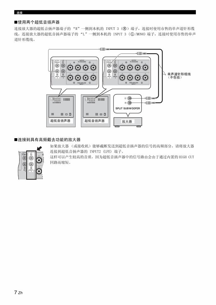
连接
■使用两个超低音扬声器
连接放大器的超低音扬声器端子的 “R”一侧到本机的 INPUT 3 ( )端子,连接时使用市售的单声道针形缆
线,连接放大器的超低音扬声器端子的“L”一侧到本机的 INPUT 3 ( /MONO) 端子,连接时使用市售的单声
道针形缆线。
■连接到具有高频截去功能的放大器
如果放大器 (或接收机)能够截断发送到超低音扬声器的信号的高频部分,请将放大器
连接到超低音扬声器的 INPUT2 (LFE) 端子。
这样可以产生较高的音质,因为超低音扬声器中的信号路由会由于通过内置的 HIGH CUT
回路而缩短。
R
L
OUTPUTTO SPEAKERS
FROM AMPLIFIER
INPUT3
INPUT 2
INPUT 1
LLL R
RR
LR
MONOOUTPUT
TO SPEAKERS
FROM AMPLIFIER
INPUT3
INPUT 2
INPUT 1
LLL R
RR
LR
MONO
OUTPUTTO SPEAKERS
FROM AMPLIFIER
LLL R
RR
LR
MONO
OUTPUTTO SPEAKERS
FROM AMPLIFIER
LLL R
RR
LR
MONO
INPUT3
INPUT 2
INPUT 1
INPUT3
INPUT 2
INPUT 1
单声道针形缆线(不包括)
放大器超低音扬声器超低音扬声器
LL R
RR
R
MONO
INPUT3
INPUT 2
7 Zh

连接
中文
使用市售的扬声器缆线 , 将放大器 ( 和前扬声器 ) 连接到本机。请参阅下列说明进行连接。
■连接到扬声器缆线
1 从扬声器缆线两端部剥除大约 15 mm 绝缘皮。
2 拧紧裸露的导线以防短路。
3 反时针旋转旋钮以松开。
4 将一条裸露的电线插入每个端子旁的孔中。
5 顺时针旋转旋钮以紧固。
6 轻拉端子中的缆线以测试连接是否稳固。
• 不要让裸露的扬声器导线互相接触,因为这会导致
本机或放大器或两者的损坏。
• 连接时,扬声器缆线越短越好。 不要包扎或捆卷剩
余的缆线。 如果连接错误,将没有声音从本机或扬
声器,或两者之中输出。
• 确认扬声器端子的极性 + 和 - 准确无误。 如果这些
缆线反向,声音会有些不自然或缺乏低音。
• 不要将绝缘表皮插入到孔里。 也许不发出声响。
■香蕉插头连接
1 拧紧旋钮。
2 将香蕉形插头插入相应的端子的端部。
连接到没有装备有超低音扬声器 (线输出)端子的放大器2
注
1 2
5
34
15 mm 12
8 Zh

连接
当你的放大器具有一套前扬声器端子时
使用市售的扬声器缆线,连接放大器的扬声器端子到本机的 INPUT 1 端子,连接本机的 OUTPUT 端子到前扬声器。
y
通过本机连接前扬声器不影响音响质量。
■使用一个超低音扬声器
■使用两个超低音扬声器
OUTPUTTO SPEAKERS
FROM AMPLIFIER
LLL R
RR
LR
MONO
INPUT3
INPUT 2
INPUT 1OUTPUT
TO SPEAKERS
FROM AMPLIFIER
INPUT3
INPUT 2
INPUT 1
LLL R
RR
LR
MONO
前扬声器 (右) 前扬声器(左)
扬声器端子
超低音扬声器放大器
OUTPUTTO SPEAKERS
FROM AMPLIFIER
INPUT3
INPUT 2
INPUT 1
LLL R
RR
LR
MONO
OUTPUTTO SPEAKERS
FROM AMPLIFIER
INPUT3
INPUT 2
INPUT 1
LLL R
RR
LR
MONO
OUTPUTTO SPEAKERS
FROMAMPLIFIER
INPUT 3 INPUT 2
LLL R
RR
LR
MONO
OUTPUTTO SPEAKERS
FROM AMPLIFIER
LLL R
RR
LR
MONO
OUTPUTTO SPEAKERS
FROM AMPLIFIER
LLL R
RR
LR
MONO
INPUT3
INPUT 2
INPUT 1
INPUT3
INPUT 2
INPUT 1
前扬声器 (右) 前扬声器 (左)
扬声器端子
超低音扬声器(右) 放大器 超低音扬声器(左)
9 Zh
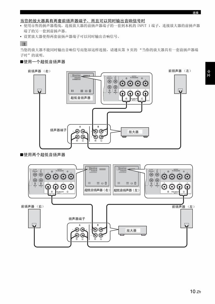
连接
中文
当您的放大器具有两套前扬声器端子,而且可以同时输出音响信号时• 使用市售的扬声器缆线,连接放大器的前扬声器端子的一套到本机的 INPUT 1 端子,连接放大器的前扬声器
端子的另一套到前扬声器。
• 设置放大器使得两套前扬声器端子可以同时输出音响信号。
当您的放大器不能同时输出音响信号而您却这样连接,请遵从第 9 页的“当你的放大器具有一套前扬声器端
子时”的说明。
■使用一个超低音扬声器
■使用两个超低音扬声器
注
OUTPUTTO SPEAKERS
FROM AMPLIFIER
LLL R
RR
LR
MONO
INPUT3
INPUT 2
INPUT 1
OUTPUTTO SPEAKERS
FROM AMPLIFIER
INPUT3
INPUT 2
INPUT 1
LLL R
RR
LR
MONO
前扬声器 (右) 前扬声器 (左)
扬声器端子放大器
超低音扬声器
OUTPUTTO SPEAKERS
FROM AMPLIFIER
LLL R
RR
LR
MONO
OUTPUTTO SPEAKERS
FROM AMPLIFIER
LLL R
RR
LR
MONO
INPUT3
INPUT 2
INPUT 1
INPUT3
INPUT 2
INPUT 1
OUTPUTTO SPEAKERS
FROM AMPLIFIER
INPUT3
INPUT 2
INPUT 1
LLL R
RR
LR
MONO
OUTPUTTO SPEAKERS
FROM AMPLIFIER
INPUT3
INPUT 2
INPUT 1
LLL R
RR
LR
MONO
前扬声器 (右)
扬声器端子
前扬声器 (左)
超低音扬声器(右) 超低音扬声器(左)
放大器
10 Zh

连接
当连接到您的放大器的扬声器端子时,如果本机或放
大器出现噪音,请使用市售的接地缆线,如图 所
示,连接您的放大器和本机的 GND( 接地)端子双方。
如果您的放大器没有 GND( 接地)端子,如图 所示,
连接固定放大器的顶盖的一颗螺钉。
当连接 GND( 接地 )端子时,请确认放大器和本机的
电源线没有插入到交流电源插座。
当所有其他连接完成后,将附带的电源线插入到本机
的电源插入,然后将电源线插入到交流电源插座。
• 不能使用其他电源线。 请使用附带的缆线。 使用其
他电源线可能引起火灾或触电。
• 不要在放大器的交流电源插座上插入电源线。 因为
可能引起声音失真或放大器的电源关断。
■VOLTAGE SELECTOR (电压选择器)开关
(仅适用于亚洲及一般机型号)
本机在背面板上没有电压选择开关。如果现在的开关设定错误、将开关设定全本地的合适电压 (110/120/220/230-240 V)范围内。如有对正确设定不确设定时、请与经销商联系。
在设置 VOLTAGE SELECTOR 之前不要将重低音扬声器连接到 AC 插座。
连接到接地端子
注
A
B
OUTPUTTO SPEAKERS
FROM AMPLIFIERINPUT 1
LLL R
RR
LR
MONO
INPUT3
INPUT 2
A B
连接电源线
注
警告
到交流插座
11 Zh

中文
在使用本机之前,请调节本机的音量平衡,以便在本机和前扬声器之间得到最佳的音量和音调平衡,调节方法
如下。
1 在确认本机背面板的电源被设置到开位置后,
按下电源,打开本机。
STANDBY/ON 指示器以绿色点亮。
2 按下 VOLUME , 设置本机的音量水平到最小
(0)。
3 打开所有其他装置的电源。
4 播放含有低频部分的音源,调节放大器的音量
到达期望的收听水平。
设置放大器的音调控制到中间位置。
5 按下 HIGH CUT / ,调节到可以得到期望反
应的位置。
通常,设置的位置对应的水平要稍微高于前扬声
器的最低频率。
* 关于前扬声器的最低频率,请参考前扬声器的
用户手册。
6 按下 VOLUME ,逐渐增加音量以调节前扬声器
和本机之间的音量平衡。
通常,设置的音量水平要高于您不使用本机时的
低音效果。
y如果您不能得到期望的反应,在此进行步骤 5 和
6。
7 按下 PHASE,选择正常或反向模式。
通常,设置此开关到反向位置。 如果您不能得到
期望的反应,设置此开关到正常位置。
8 按下 B.A.S.S.,为音源选择一个妥当的模式。
1: WIDE当电影类型的音源播放时,低频效果得到加强以便
欣赏更强烈的音响效果。
2: NORMAL当音乐或电影等类型的音源播放时,您可以欣赏到
自然的低音效果。
3: NARROW当普通的音乐音源播放时,过度的低频效果被截
去,使得音响更清晰。
使用本机
调节音响平衡
遥控器 后部面板
POWER STANDBY SLEEP
PHASE
MEMORY
PRESET
HIGH CUT VOLUME
21 3
B.A.S.S.
1
2,6 1
SUBW
STANDBY/ON
PHASE (相位)开关
多数情况下,设置此开关在反向(逆相)模式。
但是,根据所用的扬声器系统或收听环境,有时
选择常规模式(正相)位置可能会获得更佳音质。
监听声音效果,选择哪个模式更好。
12 Zh

使用本机
您可以在本机中保存 3 套喜欢的设置(音量 , 高频
截去 , 位相以及 B.A.S.S. 的设置 )。
■保存设置
在此过程中,我们使用 PRESET 1 为例。
1 在音量, 高频截去,位相以及B.A.S.S.之间调节
音响的平衡 ( 请参阅第 12 页 )。
2 按 MEMORY。前面板上的 PRESET 指示器闪烁。
3 按下 PRESET 1。PRESET 1 指示器点亮。 当前设置被保存为
PRESET 1。
y
• 在步骤 3,按下一个保存的号码覆盖旧的设置。
• 当 VOLUME 控制或 H-CUT 控制通过按下 PRESET
循环时 , 另一个 PRESET 按下时将不起作用。
■呼出设置
按下您期望呼出的 PRESET (1, 2 或 3)。
■存储器备份
即使您使用后面板的电源开关关闭本机,当您再次打
开本机时,本机将呼出上次的设置 (上次记忆功
能)。
如果电源断开一个星期以上,则设置被清除。
如果您设置睡眠定时器,本机在 120 分钟后自动进入
待机模式。
按 SLEEP。
STANDBY/ON 指示器的颜色变成橘黄色。
再次按下 SLEEP,解除睡眠定时器。
保存音响平衡的设置
POWER STANDBY SLEEP
PHASE
MEMORY
PRESET
HIGH CUT VOLUME
21 3
B.A.S.S.
H-CUT
SUBWOOFER SYSTEM NS-SW901
STANDBY/ON
STANDBY/ON PHASE
1 2 3 1 2 3
B.A.S.S. PRESET
100H
z40Hz
VOLUME100
1 1
1
2
113
遥控器 前部面板
STANDBY/ON 指示器
-SW901
3 1 2 3
PRESET
注
设置睡眠定时器
POWER STANDBY SLEEP
PHASE
MEMORY
PRESET
HIGH CUT VOLUME
21 3
B.A.S.S.
SLEEP
SUBW
STANDBY/ON
13 Zh

使用本机
中文
* 此功能仅适合于 Yamaha 的放大器,且必须符合以下条件: - 2005 以后投放市场的放大器。
- 放大器的遥控器有两个不同的 STANDBY 和 ON 按
钮。
当遥控器的 AMP ID 库代码被改变时,该功能也许不
能使用。
■设置
1 设置后面板的电源开关到关位置。
2 在按住前面板的 STANDBY/ON 开关的同时,设
置电源开关到开位置。
连续按住 STANDBY/ON 开关 3 秒钟以上。
当 STANDBY/ON 指示器闪烁 4次以后,设置完成。
■解除
1 设置后面板的电源开关到关位置。
2 在按住前面板的 STANDBY/ON 开关的同时,设置
电源开关到开位置。
以及按住 STANDBY/ON 大约 3 秒钟以上。
当 STANDBY/ON 指示器闪烁 2 次以后,设置完成。
将本机放置在遥控器的操作范围之内。 如果您远离本
机放置放大器,您也许不能使用遥控器操作本机。
使用您的放大器的遥控器操作本机的电源
注
H-CUT
SUBWOOFER SYSTEM NS-SW901
STANDBY/ON
STANDBY/ON PHASE
1 2 3 1 2 3
B.A.S.S. PRESET
100H
z40Hz
VOLUME100
POWER 开关 STANDBY/ON 开关
后部面板 前部面板
SUBW
STANDBY/ON
注
SUBW
STANDBY/ON
14 Zh

使用本机
本机的频率特性
下图所示的是当超低音扬声器与典型的前扬声器系统组合使用时各个控制的最佳调节以及频率特性。
■例 1 当与 10 cm 或 13 cm 声学悬浮 , 2 路系统前扬声器
如果您使用 NS-F901 扬声器作为前扬声器 , 在调节设置时,使用下例作为参考。
■例 2 当与 20 cm 或 25 cm 声学悬浮 , 2 路系统前扬声器
* 该图并未精确地描述实际的频率相应。
频率特性
反向模式 (绿 )
反向模式 (绿 )
频率响应图 *
20 50 100 200 500Hz40
50
60
70
80
90
dB
H-CUT 140 Hz
(H-CUT) (VOLUME)
H-CUT
140H
z40Hz
VOLUME100
(PHASE)
OOFER SYSTEM S
PHASE
1
20 50 100 200 500Hz40
50
60
70
80
90
dB
NS-SW901 (H-CUT 60 - 70 Hz)
前扬声器
频率响应图 *
(H-CUT) (VOLUME)
H-CUT
140H
z40Hz
VOLUME100
(PHASE)
OOFER SYSTEM S
PHASE
1
20 50 100 200 500Hz40
50
60
70
80
90
dB
NS-SW901 (H-CUT 50 - 60Hz)
前扬声器
频率响应图 *
15 Zh

中文
1988 年,Yamaha 推出了利用 YST (Yamaha Active
Servo Technology)的扬声器系统,以提供雄壮有力
的,高质量的低音再现。 该技术使用在放大器和扬声
器之间直接连接的方法,提供了精确的信号传送和精
密的扬声器控制。
因为该技术使用了由放大器的负阻抗驱动控制的扬声
器系统和在箱体容积量和通道之间产生的共振,所以
产生了比普通低音反射方法更大的共鸣能量 (“空气
低音”概念)。 这使得比以前更小的箱体也能再现低
音。
Yamaha 最近开发的 Advanced YST II,在 Yamaha
Active Servo Technology 的基础上又精炼了许多,
可以更好地控制驱动放大器和扬声器的能量。 从放大
器来看,扬声器阻抗根据音响频率改变。Yamaha 开发
了由负阻抗和恒量电流驱动相结合的新的电路设计,
以提供更加稳定的性能和毫不模糊的清晰低音再现。
Advanced Yamaha Active Servo Technology II
高振幅低音 通道
箱体
高级阻抗转换器
主动伺服处理放大器
低振幅信号
空气低音喇叭(亥姆霍兹共鸣器)
信号
16 Zh

当本机工作不正常时,请参阅下表。 如果您遇到的问题没有列在下面,或如果下面给出的指导不起作用,请断
开电源线,并联络距离您最近的 Yamaha 经销商或服务中心。
• 当过度水平的信号输入到本机 5 到 15 分钟,电源指示器开始闪烁,警告您这有损坏本机的功率放大器和扬声
器的危险。 如果信号输入持续 5 分钟,本机自动进入待机模式。
• 当超乎寻常幅度的信号输入时,本机的电源会立即关闭。 要再次打开本机,按下前面板的 STANDBY/ON 开关。
故障排除
问题 原因 措施
即使当 STANDBY/ON 被按下,电
源也不能接通。
电源插头连接不牢靠。 牢固地连接它。
电源开关被设置到关位置。 设置电源开关到开位置。
无声音。 音量被设置到最小位置(0)。 提高音量水平。
扬声器缆线没有牢固地连接。 牢固地连接它们。
来自放大器的信号太小。 提高放大器或者连接到放大器的装置
的音量。
来自放大器的超低音扬声器输出端子的
信号没有输出。
确认放大器上的扬声器模式的设置。
音量水平太低。 扬声器缆线没有正确地连接。 所有连接必须正确,也就是说,L
( 左 ) 到 L, R ( 右 ) 到 R, “+” 到
“+”,“-”到“-”。
位相的设置不妥。 设置位相到其他位置。
播放的音源缺少低频。 播放具有低频的音源。
设置 H-CUT 开关到更高位置。
这被驻波影响。 重新放置超低音扬声器或变换其放置
的角度。
遥控器不起作用。 距离或角度错误。 使用遥控器必须在最大为 6 m 的范围
内,且不能偏离前面板轴心超过 30
度。
直射阳光或光照(来自逆变器型荧光灯)
影响了本机的遥控器传感器。
重新放置本机。
电池微弱。 更换所有电池。
本机的遥控器信号接收器和遥控器之间
有障碍物。
除去障碍物。
不能使用放大器的遥控器打开本
机。(当设置 “使用您的放大器
的遥控器操作本机的电源”)
距离或角度错误。 将本机放置在遥控器的操作范围之内。
室内断路器关断。 当高电平的信号输入时,本机消耗很大的
电力。
减小放大器等连接在本机的装置的音
量,或关闭其他不使用的装置的电源。
某个物体掉落到出音孔。 不要尝试移动该物体。尝试移动该物体可
能会造成故障。
请联系授权的 Yamaha 销售商或服务中
心。
注
17 Zh

中文
类型.... Advanced Yamaha Active Servo Technology II
驱动器................... 25 cm 圆锥体低音喇叭 磁屏蔽类型
放大器输出 (100 Hz, 4 欧姆 , 10% T.H.D)........................................ 600 W
频率响应 ..................... 18 Hz 到 160 Hz
电源
美国和加拿大型号 ........... AC 120 V, 60 Hz英国和欧洲型号 ............. AC 230 V, 50 Hz澳大利亚型号 ............... AC 240 V, 50 Hz通用和亚洲型号........ AC 110/120/220/230-240 V, 50/60 Hz韩国型号 ................... AC 220 V, 60 Hz中国型号 ................... AC 220 V,50 Hz
功耗 .................................... 180 W
待机功耗 ................................ 0.5 W
尺寸 (宽 x 高 x 深)
.................. 410 mm x 457 mm x 462 mm
重量 .................................... 32 kg
请注意,规格时有变化,恕不另行通知。
规格
18 Zh
Yamaha 서브우퍼시스템을 선택해 주셔서 감사합니다 .
제품을 사용하기 전에 다음의 조작상의 주의사항을 읽으십시오 . 아래의 주의사항을 따르지 않아 발생한 어떠한 손해 또는 상해에 하여도 Yamaha 는 책임을 지지 않습니다 .
• 제품이 최상의 성능을 발휘할 수 있도록 본 설명서를 주의 깊게 읽으십시오 . 나중에 참조할 수 있도록 설명서를안전한 장소에 보관하십시오 .
• 서늘하고 건조하고 청결한 곳에 제품을 설치하고 , 창문이나 발열기구 , 과도한 진동 , 먼지 , 수분 및 추위로부터멀리 떨어지도록 하십시오 . “윙윙”거리는 소리가 나는곳( 변압기 , 모터 등 ) 은 피하십시오 . 화재나 감전의 위험이 있으니 제품을 물과 접촉하지 않게 하십시오 .
• 후면 패널에 명시되어 있는 전압을 사용하십시오. 명시된 전압보다 높은 전압을 본 제품에 사용하는 것은 위험하며 화재 또는 감전의 원인이 될 수 있습니다 .
• 번개로 인한 손상을 방지하기 위하여 뇌우시에는 AC전원 플러그를 콘센트에서 뽑으십시오 .
• 스위치 , 콘트롤 및 연결선에 무리한 힘을 가하지 마십시오 . 제품을 이동시킬 때에는 우선 전원 플러그를 빼고다른 장치에 연결된 연결선을 분리하십시오 . 절 로 연결선을 직접잡아당겨서는 안 됩니다 .
• 이 제품은 전력 증폭장치를 내장하고 있으므로 후면 패널에서 열이 발생합니다. 화재나 기타 손상으로부터 제품을 보호하기 위하여 제품의 윗면 , 뒷면 , 양측면과 벽사이에 최소한 20 cm 의 공간을 두어 설치하십시오 . 또한 후면 패널이 바닥이나 다른 표면을 향하지 않도록 하십시오 .
• 제품의 열 방출을 막지 않도록 제품 후면 패널을 신문지 ,테이블보 및 커튼 등으로 덮지 마십시오 . 제품 내부의온도가 상승하면 화재나 제품 손상이 발생하거나 신체적 상해를 입을 수 있습니다 .
• 다음과 같은 물체를 제품 위에 올려 놓지 마십시오 . 유리 , 도자기 , 금속 등- 유리 등이 진동으로 떨어지거나 깨지면 신체에 상해
를 입힐 수 있습니다 .- 불이 켜진 촛불
촛불이 진동으로 떨어지면 화재를 일으키거나 신체에상해를 입힐 수 있습니다 .
- 물이 들어있는 용기물이 들어있는 용기가 진동으로 떨어지거나 물이 엎질러지면 스피커 손상이나 감전의 위험이 있습니다 .
• 물방울 등과 같은 이물질이 떨어질 수 있는 곳에 제품을놓지 마십시오 . 화재나 제품 손상이 발생하거나 신체적상해를 입을 수 있습니다 .
• 본 제품의 오른쪽에 위치한 YST 포트에 절 로 손이나이물질을 넣지 마십시오 . 본 제품을 이동시킬 때에는 포트를 잡지 마십시오 . 제품 손상이 발생하거나 신체적 상해를 입을 수 있습니다 .
• 본 제품의 YST 포트 근처에 절 로 깨지기 쉬운 물체를놓지 마십시오 . 기압으로 인해 물체가 쓰러지거나 떨어지면 제품 손상이 발생하거나 신체적 상해를 입을 수 있습니다 .
• 제품의 캐비닛을 절 로 열지 마십시오. 본 제품은 고압의 전류를 사용하므로 감전될 수 있습니다 . 또한 , 신체적 상해가 발생하거나 제품이 손상될 수 있습니다 .
• 가습기를 사용하는 경우에는 제품 주위에 충분한 공간을 확보하거나 과도한 습도를 억제하여 제품 내부에 물방울이 응축되지 않도록 하십시오 . 물방울이 맺히면 화재 또는 제품 손상이 발생하거나 감전될 수 있습니다 .
• 제품에서 발생되는 수퍼 베이스의 주파수로 인해 턴테이블의 소리가 울릴 수 있습니다 . 이러한 경우에는 제품을 턴테이블에서 멀리 떨어뜨려 설치하십시오 .
• 높은 볼륨으로 특정 사운드가 연속적으로 출력되는 경우에는 제품이 손상될 수 있습니다 . 예를 들어 , 테스트디스크의 20 Hz - 50 Hz 사인 파동 , 전자 악기의 저음 등이 연속적으로 출력되거나 턴테이블의 바늘이 디스크표면에 닿을 때 본 기기가 손상되지 않도록 볼륨을 줄이십시오 .
• 만일 자연스럽지 않고 간헐적인 두드리는 듯한 사운드왜곡이 발생하면 볼륨을 낮추십시오 . 영화 사운드 트랙의 저주파수 , 저음의 헤비 사운드 또는 팝 음악의 경과구가 너무 크게 재생되면 스피커 시스템을 손상시킬 수있습니다 .
• 수퍼 베이스 주파수에서 발생하는 진동은 TV의 영상을찌그러뜨릴 수 있습니다 . 이런 경우에는 본 기기를 TV 로부터 멀리 떨어뜨려 놓으십시오 .
• 화학 용제로 제품을 닦으면 표면이 손상됩니다. 깨끗하고 마른 헝겊을 사용하십시오 .
• 스피커의 고장이라고 결론짓기 전에 일반 조작 에러에 해서는 “문제 해결”절을 읽어 보십시오 .
• 콘센트에서 가깝고 AC 전원 플러그에 쉽게 닿을 수 있는 장소에 본 기기를 설치하십시오 .
• 건전지를 직사광선, 불꽃 등과 같이 과도한 화기에 노출시키지 마십시오 . 배터리를 폐기할 때에는 해당 지역의 규정을 따르십시오 .- 어린이의 손이 닿지 않는 곳에 배터리를 보관하십시오 .
어린이가 배터리를 입에 넣으면 위험할 수 있습니다 .- 건전지가 오래되면 리모콘의 유효 작동 범위가 현저하
게 짧아집니다 . 이러한 경우 , 가능한 한 빠른 시일 내에 새 건전지 2 개로교체하십시오 .
- 오래된 건전지를 새 건전지와 함께 사용하지 마십시오 .- 서로 다른 종류의 건전지 ( 알카라인 및 망간 건전지 등
) 를 함께사용하지 마십시오 . 서로 다른 건전지 종류라도 동일한 모양과색상을 지닐 수 있으므로 포장지를 주의 깊게 읽어 보십시오 .
- 다 쓴 건전지는 누액할 수 있습니다 . 건전지가 누액한 경우 , 즉시 누액 건전지를 폐기하십시오 . 누출된 물질을 만지거나 의류에 닿지 않도록 하십시오 . 새 건전지를 장착하기 전에 건전지함을 깨끗이 닦아 주십시오 .
- 본 기기를 장시간 사용하지 않을 경우에는 기기에서 배터리를 빼십시오 . 기기에서 배터리를 빼지 않으면 배터리가 소진되며 , 기기에 손상을 야기할 수 있는 배터리 액이 누출될 수 있습니다 .
- 다 쓴 건전지를 일반 쓰레기통에 버리지 마십시오 . 해당 지역규정에 따라 올바르게 처리하십시오 .
• 제품을 안전하게 배치하고 설치하는 것은 사용자의 책임
입니다 . Yamaha 는 사용자가 스피커를 잘못 배치하거
나 설치함으로써 발생한 사고에 하여 책임지지않습니
다 .
주의 : 제품을 작동시키기 전에 본 설명서를 읽으십시오 .
경고화재나 감전의 위험을 줄이려면 본 제품에 비나 수분이닿지 않게 하십시오 .
i Ko

한국
어
• VOLTAGE SELECTOR
( 아시아 및 일반 모델용 )제품을 AC 전원에 연결하기 전에 제품의 후면 패널에 있는 VOLTAGE SELECTOR 스위치를 해당 전압으로 설정해야 합니다 . 이 제품의 전압은110/120/220/230-240 V AC, 50/60 Hz 입니다 .
시작하기 ....................................................................1
특징 .............................................................................. 1
본 설명서에 하여 .................................................... 1
부속품 ........................................................................... 1
각부 명칭 및 기능 ........................................................ 2
리모콘 준비 .................................................................. 4
배치 ............................................................................5
서브우퍼 방향............................................................... 5
연결 ............................................................................6
서브우퍼 ( 라인 출력 ) 터미널이 장착된 앰프에 연결 .................................................................. 6
서브우퍼 ( 라인 출력 ) 터미널이 없는 앰프에 연결 .................................................................. 8
접지 터미널에 연결....................................................11
전원 케이블 연결 .......................................................11
본 기기 사용법 ....................................................... 12
사운드 밸런스 조절....................................................12
사운드 밸런스 설정 저장...........................................13
슬립 타이머 설정 .......................................................13
앰프 리모콘을 사용하여 본 기기의 전원 조작 ........14
주파수 특성 ................................................................15
Advanced Yamaha Active Servo Technology II .............................. 16
문제 해결 ................................................................ 17
사양 ......................................................................... 18
주의배터리를 올바르게 교체하지 않으면 폭발할 위험이 있습니다 . 동일하거나 같은 형식의 배터리만 교체하십시오 .
본 기기를 CRT 방식 ( 브라운관 ) TV 와 너무 가까운 곳에 놓으면 화면 색상이 나빠질 수도 있습니다 . 그런 경우에는 본 기기를 TV 에서 먼 곳으로 옮기십시오 .
본 제품은 본체 전원을 꺼도 콘센트에 연결되어 있으면 AC 전원이 차단되지 않습니다 . 본 제품은 이와 같은 상황에서 전력 소모를 최소화하도록 설계되었습니다 .
스피커 관리스피커 표면의 광택을 유지하려면 부드러운 마른 헝겊으로 닦으십시오 . 마감 표면의 손상을 예방하려면 알코올 , 벤진 , 시너 등과 같은 화학 용제를 사용하지 마십시오 . 또한 젖은 헝겊이나 화학 용제가 함유된 헝겊을 사용하지 마십시오 . 스피커 윗면을 플라스틱 시트나 비닐 시트로 덮지 마십시 . 그렇지 않으면 마감재가 벗겨지거나 색상이 변질되거나 시트가 표면에 달라붙을 수 있습니다 .
목차
1
2
ii Ko
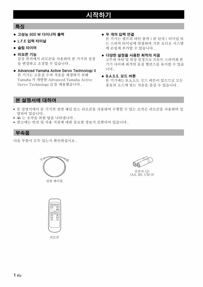
◆ 고성능 600 W 다이나믹 출력
◆ L.F.E 입력 터미널
◆ 슬립 타이머
◆ 리모콘 기능감상 위치에서 리모콘을 사용하여 본 기기의 설정을 변경하고 조정할 수 있습니다 .
◆ Advanced Yamaha Active Servo Technology II본 기기는 고음질 수퍼 저음을 재생하기 위해 Yamaha 가 개발한 Advanced Yamaha Active Servo Technology II 를 채용했습니다 .
◆ 두 개의 입력 연결본 기기는 앰프의 라인 출력 ( 핀 단자 ) 터미널 또는 스피커 터미널에 연결하여 기존 오디오 시스템에 손쉽게 추가할 수 있습니다 .
◆ 다양한 설정을 사용한 최적의 저음고주파 차단 및 위상 설정으로 프론트 스피커와 본 기기 사이에 최적의 음질 밸런스를 유지할 수 있습니다 .
◆ B.A.S.S. 모드 버튼본 기기에는 B.A.S.S. 모드 버튼이 있으므로 모든 종류의 소스에 맞는 저음을 즐길 수 있습니다 .
• 본 설명서에서 본 기기의 전면 패널 또는 리모콘을 사용하여 수행할 수 있는 조작은 리모콘을 사용하여 설명되어 있습니다 .
• y 는 조작을 위한 팁을 나타냅니다 .• 참고에는 안전 및 사용 지침에 한 중요한 정보가 포함되어 있습니다 .
다음 부품이 모두 있는지 확인하십시오 .
시작하기
특징
본 설명서에 하여
부속품
전원 케이블
리모콘
POWER STANDBY SLEEP
PHASE
MEMORY
PRESET
HIGH CUT VOLUME
21 3
B.A.S.S.
건전지 (2)(AA, R6, UM-3)
1 Ko
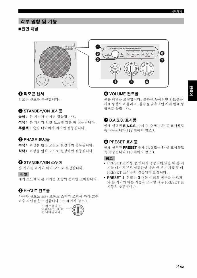
시작하기
한국
어한
국어
■전면 패널
1 리모콘 센서
리모콘 신호를 수신합니다 .
2 STANDBY/ON 표시등
녹색 : 본 기기가 켜지면 점등됩니다 .
적색 : 본 기기가 안전 모드에 있을 때 점등됩니다 .
주황색 : 슬립 타이머가 켜지면 점등됩니다 .
3 PHASE 표시등
녹색 : 위상을 반전 모드로 설정하면 점등됩니다 .
적색 : 위상을 일반 모드로 설정하면 점등됩니다 .
4 STANDBY/ON 스위치
본 기기를 켜거나 기 모드로 설정합니다 .
기 모드에서 본 기기는 소량의 전력만 소비합니다 .
5 H-CUT 컨트롤
사용자 선호도 또는 프론트 스피커 조합에 따라 고주파수 차단점을 조절합니다 (12 페이지 참조 ).
6 VOLUME 컨트롤
볼륨 레벨을 조절합니다 . 볼륨을 높이려면 컨트롤을 시계 방향으로 돌리고 , 볼륨을 낮추려면 시계 반 방향으로 돌립니다 .
7 B.A.S.S. 표시등
현재 선택된 B.A.S.S. 숫자 (1, 2 또는 3) 를 표시하도록 점등됩니다 (12 페이지 참조 ).
8 PRESET 표시등
현재 선택된 PRESET 숫자 (1, 2 또는 3) 를 표시하도록 점등됩니다 (13 페이지 참조 ).
• PRESET 표시등 중 하나가 점등되어 있을 때 본 기기를 기 모드로 설정하면 다음 번 본 기기를 켤 때 PRESET 표시등이 점등되지 않습니다 .
• PRESET 1, 2 또는 3 버튼 이외의 버튼을 누르거나 본 기기의 다른 기능을 조작할 경우 PRESET 표시등은 소등됩니다 .
각부 명칭 및 기능
H-CUT
SUBWOOFER SYSTEM NS-SW901
STANDBY/ON
STANDBY/ON PHASE
1 2 3 1 2 3
B.A.S.S. PRESET
140H
z40Hz
VOLUME100
1
23
4 5 6
7
8
참고
본 컨트롤의 눈금 하나는 10 Hz를 나타냅니다 .
H-CUT
140H
z40Hz
참고
2 Ko

시작하기
■후면 패널
1 GND 터미널연결 정보웝 해서는 11 페이지를 참고하십시오 .
2 INPUT 3 터미널연결 정보에 해서는 6~7 페이지를 참고하십시오 .
3 INPUT 2 (LFE) 터미널연결 정보웝 해서는 7 페이지를 참고하십시오 .
4 OUTPUT 터미널연결 정보에 해서는 9 페이지를 참고하십시오 .
5 INPUT 1 터미널연결 정보에 해서는 9~10 페이지를 참고하십시오 .
6 AC IN동봉된 전원 케이블을 연결합니다 (11 페이지 참조 ).
7 POWER 스위치본 기기의 전원 (ON/OFF) 을 전환합니다 .일반적으로 이 스위치를 ON 위치로 설정합니다 . 본 기기를 장시간 사용하지 않는 경우에는 스위치를 OFF 위치로 설정합니다 .
■리모콘
1 STANDBY
본 기기를 기 모드로 설정합니다 .
기 모드에서 본 기기는 소량의 전력만 소비합니다 .
2 POWER본 기기를 켭니다 .
3 B.A.S.S.소스에 적합한 모드를 선택합니다 .B.A.S.S. 를 누를 때마다 B.A.S.S. 표시등은 1, 2 및 3 간에 변경됩니다 .
4 PRESETB.A.S.S., 볼륨 , 고주파 차단 및 위상 설정을 저장하거나 호출합니다 (13 페이지 참조 ).
5 HIGH CUT /사용자 선호도 또는 프론트 스피커 조합에 따라 고주파수 차단점을 조절합니다 (12 페이지 참조 ).
6 SLEEP슬립 타이머를 설정합니다 (13 페이지 참조 ).
7 PHASE위상 모드를 전환합니다 .일반적으로 본 기기를 반전 위치로 설정합니다 . 그러나 스피커 시스템 또는 감상 조건에 따라 이 스위치를 일반 위치로 설정하면 더 나은 음질을 얻을 수 있는 경우도 있습니다 . 사운드를 모니터링하면서 더 나은 위치를 선택합니다 .
8 MEMORYB.A.S.S., 볼륨 , 고주파 차단 및 위상 설정을 저장합니다 (13 페이지 참조 ).
9 VOLUME /본 기기의 볼륨을 조절합니다 .
OUTPUTTO SPEAKERS
FROM AMPLIFIER
INPUT3
INPUT 2
INPUT 1
LLL R
RR
LR
MONO
OUTPUTTO SPEAKERS
FROM AMPLIFIER
INPUT3
INPUT 2
INPUT 1
LLL R
RR
LR
MONO
POWER
ON
OFF
POWER
ON
OFF
1 23
5
6 7
참고
POWER STANDBY SLEEP
PHASE
MEMORY
PRESET
HIGH CUT VOLUME
21 3
B.A.S.S.
123
4
5 9
87
6
3 Ko

시작하기
한국
어한
국어
■리모콘에 건전지 장착
1 건전지 덮개의 표시를 눌러 덮개를 엽니다 .
2 건전지 함 내부의 표시 (+/-) 에 따라 동봉된 건
전지 종류 AA, R6, UM-3 두 개를 삽입합니다 .
3 건전지 덮개를 닫습니다 .
건전지 교체
리모콘의 작동 범위 감소와 같은 조건이 감지되면 건전지를 모두 교체합니다 .
■리모콘 사용
리모콘은 지향성 적외선을 송출합니다 . 조작 중에 본체의 리모콘 센서에 리모콘을 직접 조준하십시오 .
리모콘 취급
리모콘에 액체를 쏟지 않도록 주의하십시오 .
리모콘을 떨어뜨리지 않도록 주의하십시오 .
다음과 같은 장소에 리모콘을 두지 마십시오 :- 히터 근처 또는 욕실과 같은 온도가 높고 습도가
많은 장소- 매우 추운 장소- 먼지가 많은 장소
리모콘 준비
31
2
리모콘 센서
약 6 m
4 Ko

오디호 신호의 저역 주파수는 장파장의 특성을 지니고 있기 때문에 사람의 귀에는 거의 무지향성입니다 . 최저 음역 에서는 스테레오 이미지가 성되지 않습니다 . 따라서 단 한 개의 서브우퍼만으로도 고급 수퍼 베이스 음향을 충분히 재현할 수 있습니다 그러나 ( 좌측 및 우측 프론트 스피커럼 ) 두 개의 서브우퍼를 이용하면 음향 경험을 개선시킬 수 있습니다 .
최적의 효과를 위해 서브우퍼를 그림 , 또는 와 같이 배치하십시오 .
: 서브우퍼 : 프론트 스피커
서브우퍼가 한 개인 경우
서브우퍼를 좌측 또는 우측 프론트 스피커의 바깥쪽에 배치하십시오 .
서브우퍼를 좌측 및 우측 프론트 스피커 사이에 배치
서브우퍼를 좌측 및 우측 프론트 사이에 배치하는 경우에는 벽쪽을 향해 비스듬히 배치해야 더 나은 효과를 얻을 수 있습니다 .
두 개의 서브우퍼 이용
각 프론트 스피커의 바깥쪽에 서브우퍼를 배치하십시오 .
• 본 기기는 자기 차폐 설계가 적용되어 있습니다 . 그러나 CRT 형 TV 세트와 너무 가깝게 배치하는 경우 화면 색상이 손상될 수 있습니다 . 이 경우 TV 를 리 이동하십시오 .
• 스피커 볼륨이 너무 큰 경우에는 가구나 창문 유리와 공명 현상을 일르켜서 서브우퍼의 진동을 야기할 수 있습니다 . 이 경우에는 볼륨 레벨을 낮추시오 . 공명 현상을 최소화하려면 음향 진동을 효과적으로 흡수하는 두꺼운 커튼이나 유사한 천을 사용하십시오 . 서브우퍼 위치를 변경하는 것도 움이 될 수 있습니다 .
배치
서브우퍼 방향
A B C
A
또는
B
또는
C
참고아래 그림과 같이 배치할 수도 있습니다 . 그러나 서브우퍼 시스템이 직접 벽면을 향하게 배치하는 경우 직접음과 반사음 사이의 간섭에 따른 위상 쇄로 인해 베이스 효과가 저하
될 수 있습니다 . 이 현상을 방지하려면 서브우퍼 시스템을 비스듬하게 배치하십시오 .
( 참조 : 그림 , 및 ).A B C
중복파로 인해 서브우퍼에서 충분한 수퍼 베이스 음향을 얻지 못할 수도 있습니다 .
참고
5 Ko

한국
어한
국어
앰프에 서브우퍼 ( 라인 출력 ) 터미널이 있는 경우에는 6~7 페이지를 참고하고 , 앰프에 서브우퍼 ( 라인 출력 ) 터미널이 없는 경우에는 8~10 페이지를 참고하십시오 .
• 콤포넌트 간 연결을 모두 완료할 때까지 본 기기 및 다른 콤포넌트의 전원 코드를 AC 콘센트에 연결하지 마십시오 .
• 좌측 채널 (L), 우측 채널 (R), “+”( 적색 ) 및 “-”( 검은색 ) 을 올바로 연결하십시오 . 또한 본 기기에 연결된 각 콤포넌트의 사용 설명서도 참고하십시오 .
• 연결 방법 또는 터미널 이름은 콤포넌트에 따라 다를 수 있습니다 . 콤포넌트의 사용 설명서를 참고하십시오 .
앰프에 한 개의 채널 서브우퍼 터미널이 있는 경우
시중에서 판매하는 모노 핀 케이블 사용하여 앰프의 서브우퍼 ( 또는 저주파 통과 등 ) 터미널을 본 기기의 INPUT 3( /MONO) 터미널에 연결합니다 .
앰프에 두 개의 채널 서브우퍼 터미널이 있는 경우
■하나의 서브우퍼 사용
시중에서 판매하는 오디오 핀 케이블 사용하여 앰프의 “L”쪽 서브우퍼 터미널을 본 기기의 INPUT 3( /MONO) 터미널에 연결하고 , 앰프의 “R”쪽 서브우퍼 터미널을 본 기기의 INPUT 3( ) 터미널에 연결합니다 .
• 일부 앰프에는 PRE OUT 이라는 라인 출력 터미널이 있습니다 . 본 기기를 앰프의 PRE OUT 터미널에 연결하는 경우 앰프에 최소한 두 개의 PRE OUT 터미널 세트가 있는지 확인합니다 . 앰프에 한 개의 PRE OUT 터미널 세트만 있는 경우에는 본 기기를 PRE OUT 터미널에 연결하지 마십시오 . 신 본 기기를 앰프의 스피커 터미널에 연결하십시오 ( 8~9 페이지 참고 ).
• 앰프의 모노 라인 출력 터미널에 연결하는 경우 INPUT 3( /MONO) 터미널에 연결하십시오 .• 앰프의 라인 출력 터미널에 연결하는 경우 본 기기의 후면 패널에 있는 OUTPUT 터미널에 다른 스피커를
연결할 수 없습니다 . 다른 스피커를 연결하면 사운드가 출력되지 않습니다 .
연결
참고
서브우퍼 ( 라인 출력 ) 터미널이 장착된 앰프에 연결1
L
OUTPUTTO SPEAKERS
FROM AMPLIFIER
LLL R
RR
LR
MONO
INPUT3
INPUT 2
INPUT 1
OUTPUTTO SPEAKERS
FROM AMPLIFIER
INPUT3
INPUT 2
INPUT 1
LLL R
RR
LR
MONO
POWER
ON
OFF
앰프
모노 핀 케이블 ( 동봉되지 않음 )
서브우퍼
L R
참고
L
OUTPUTTO SPEAKERS
FROM AMPLIFIER
LLL R
RR
LR
MONO
INPUT3
INPUT 2
INPUT 1
OUTPUTTO SPEAKERS
FROM AMPLIFIER
INPUT3
INPUT 2
INPUT 1
LLL R
RR
LR
MONO
POWER
ON
OFF
오디오 핀 케이블( 동봉되지 않음 )
앰프
서브우퍼
6 Ko

연결
■두 개의 서브우퍼 사용
시중에서 판매하는 모노 핀 케이블 사용하여 앰프의“R”쪽 서브우퍼 터미널을 본 기기의 INPUT 3( ) 터미널에 연결하고 앰프의“L”쪽 서브우퍼 터미널을 본 기기의 INPUT 3( /MONO) 터미널에 연결합니다 .
■고주파 차단 기능이 장착된 앰프에 연결
앰프 ( 또는 수신기 ) 가 서브우퍼로 전송되는 신호에서 고주파를 차단하는 기능이 있는 경우 앰프를 서브우퍼의 INPUT2 (LFE) 단자에 연결하십시오 . 이를 통해 서브우퍼에서 라우팅되는 신호가 내장 HIGH CUT 회로를 우회함으로써 경로가 짧아져서 고품질의 음향을 얻을 수 있습니다 .
RL
POWER
ON
OFF
OUTPUTTO SPEAKERS
FROM AMPLIFIER
INPUT3
INPUT 2
INPUT 1
LLL R
RR
LR
MONOOUTPUT
TO SPEAKERS
FROM AMPLIFIER
INPUT3
INPUT 2
INPUT 1
LLL R
RR
LR
MONO
OUTPUTTO SPEAKERS
FROM AMPLIFIER
LLL R
RR
LR
MONO
OUTPUTTO SPEAKERS
FROM AMPLIFIER
LLL R
RR
LR
MONO
INPUT3
INPUT 2
INPUT 1
INPUT3
INPUT 2
INPUT 1
POWER
ON
OFF
모노 핀 케이블( 동봉되지 않음 )
앰프서브우퍼서브우퍼
LL R
RR
R
MONO
INPUT3
INPUT 2
7 Ko
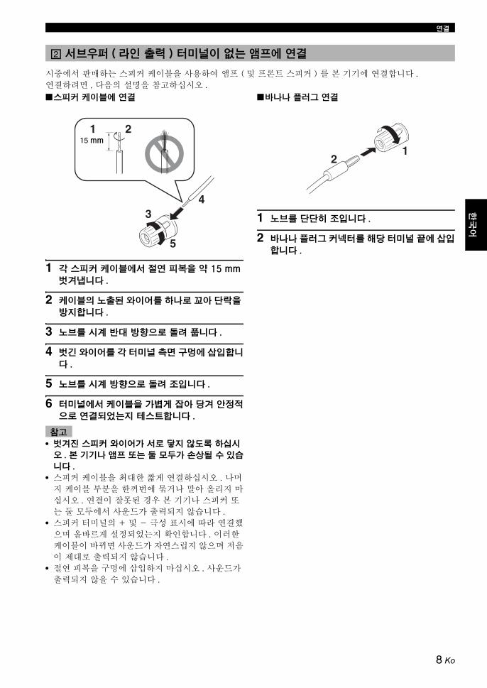
연결
한국
어한
국어
시중에서 판매하는 스피커 케이블을 사용하여 앰프 ( 및 프론트 스피커 ) 를 본 기기에 연결합니다 . 연결하려면 , 다음의 설명을 참고하십시오 .
■스피커 케이블에 연결
1 각 스피커 케이블에서 절연 피복을 약 15 mm
벗겨냅니다 .
2 케이블의 노출된 와이어를 하나로 꼬아 단락을
방지합니다 .
3 노브를 시계 반 방향으로 돌려 풉니다 .
4 벗긴 와이어를 각 터미널 측면 구멍에 삽입합니
다 .
5 노브를 시계 방향으로 돌려 조입니다 .
6 터미널에서 케이블을 가볍게 잡아 당겨 안정적
으로 연결되었는지 테스트합니다 .
• 벗겨진 스피커 와이어가 서로 닿지 않도록 하십시
오 . 본 기기나 앰프 또는 둘 모두가 손상될 수 있습
니다 .
• 스피커 케이블을 최 한 짧게 연결하십시오 . 나머지 케이블 부분을 한꺼번에 묶거나 말아 올리지 마십시오 . 연결이 잘못된 경우 본 기기나 스피커 또는 둘 모두에서 사운드가 출력되지 않습니다 .
• 스피커 터미널의 + 및 - 극성 표시에 따라 연결했으며 올바르게 설정되었는지 확인합니다 . 이러한 케이블이 바뀌면 사운드가 자연스럽지 않으며 저음이 제 로 출력되지 않습니다 .
• 절연 피복을 구멍에 삽입하지 마십시오 . 사운드가 출력되지 않을 수 있습니다 .
■바나나 플러그 연결
1 노브를 단단히 조입니다 .
2 바나나 플러그 커넥터를 해당 터미널 끝에 삽입
합니다 .
서브우퍼 ( 라인 출력 ) 터미널이 없는 앰프에 연결2
참고
1 2
5
34
15 mm
12
8 Ko

연결
앰프에 한 세트의 프론트 스피커 터미널이 있는 경우
시중에서 판매하는 스피커 케이블을 사용하여 앰프의 스피커 터미널을 본 기기의 INPUT 1 터미널에 연결하고 본 기기의 OUTPUT 터미널을 프론트 스피커에 연결합니다 .
y
본 기기를 통해 프론트 스피커를 연결해도 음질에는 영향을 주지 않습니다 .
■하나의 서브우퍼 사용
■두 개의 서브우퍼 사용
OUTPUTTO SPEAKERS
FROM AMPLIFIER
LLL R
RR
LR
MONO
INPUT3
INPUT 2
INPUT 1OUTPUT
TO SPEAKERS
FROM AMPLIFIER
INPUT3
INPUT 2
INPUT 1
LLL R
RR
LR
MONO
POWER
ON
OFF
프론트 스피커 ( 오른쪽 ) 프론트 스피커 ( 왼쪽 )
스피커 터미널
앰프서브우퍼
OUTPUTTO SPEAKERS
FROM AMPLIFIER
INPUT3
INPUT 2
INPUT 1
LLL R
RR
LR
MONO
OUTPUTTO SPEAKERS
FROM AMPLIFIER
INPUT3
INPUT 2
INPUT 1
LLL R
RR
LR
MONO
OUTPUTTO SPEAKERS
FROMAMPLIFIER
INPUT 3 INPUT 2
LLL R
RR
LR
MONO
OUTPUTTO SPEAKERS
FROM AMPLIFIER
LLL R
RR
LR
MONO
OUTPUTTO SPEAKERS
FROM AMPLIFIER
LLL R
RR
LR
MONO
INPUT3
INPUT 2
INPUT 1
INPUT3
INPUT 2
INPUT 1
POWER
ON
OFF
POWER
ON
OFF
프론트 스피커 ( 오른쪽 ) 프론트 스피커 ( 왼쪽 )
스피커 터미널
서브우퍼 ( 오른쪽 ) 앰프 서브우퍼 ( 왼쪽 )
9 Ko

연결
한국
어한
국어
앰프에 두 세트의 프론트 스피커 터미널이 있으며 두 터미널에서 사운드 신호를 동시에 출력할 수 있는 경우• 시중에서 판매하는 스피커 케이블을 사용하여 앰프에 있는 한 프론트 스피커 터미널 세트를 본 기기의
INPUT 1 터미널에 연결하고 , 앰프에 있는 다른 프론트 스피커 터미널 세트를 프론트 스피커에 연결합니다 .
• 두 세트의 프론트 스피커 터미널에서 사운드 신호를 동시에 출력하도록 앰프를 설정합니다 .
이런 방법으로 연결해도 사운드 신호가 앰프에서 동시에 출력되지 않으면 9 페이지의 “앰프에 한 세트의 프론트 스피커 터미널이 있는 경우”를 따르십시오 .
■하나의 서브우퍼 사용
■두 개의 서브우퍼 사용
참고
OUTPUTTO SPEAKERS
FROM AMPLIFIER
LLL R
RR
LR
MONO
INPUT3
INPUT 2
INPUT 1
OUTPUTTO SPEAKERS
FROM AMPLIFIER
INPUT3
INPUT 2
INPUT 1
LLL R
RR
LR
MONO
POWER
ON
OFF
프론트 스피커 ( 오른쪽 ) 프론트 스피커 ( 왼쪽 )
스피커 터미널앰프
서브우퍼
OUTPUTTO SPEAKERS
FROM AMPLIFIER
LLL R
RR
LR
MONO
OUTPUTTO SPEAKERS
FROM AMPLIFIER
LLL R
RR
LR
MONO
INPUT3
INPUT 2
INPUT 1
INPUT3
INPUT 2
INPUT 1
OUTPUTTO SPEAKERS
FROM AMPLIFIER
INPUT3
INPUT 2
INPUT 1
LLL R
RR
LR
MONO
OUTPUTTO SPEAKERS
FROM AMPLIFIER
INPUT3
INPUT 2
INPUT 1
LLL R
RR
LR
MONO
POWER
ON
OFF
POWER
ON
OFF
프론트 스피커 ( 오른쪽 )
스피커 터미널
프론트 스피커 ( 왼쪽 )
서브우퍼 ( 오른쪽 ) 서브우퍼 ( 왼쪽 )
앰프
10 Ko

연결
앰프의 스피커 터미널에 연결하는 경우 기기 또는 앰프에 햄 노이즈가 발생하는 경우 그림 에 표시된 로 시중에서 판매하는 접지 와이어를 사용하여 앰프 및 본 기기의 GND( 접지 ) 터미널을 모두 연결합니다 .
앰프에 GND( 접지 ) 터미널이 없는 경우 그림 에 표시된 로 앰프의 상단 덮개를 조이는 나사를 연결합니다 .
GND( 접지 ) 터미널을 연결하는 경우 앰프 및 본 기기의 전원 케이블이 AC 콘센트에 연결되지 않았는지 확인합니다 .
다른 모든 연결이 완료되면 동봉된 전원 케이블을 본 기기의 AC IN 에 연결한 다음 전원 케이블을 AC 콘센트에 꽂습니다 .
• 다른 전원 케이블을 사용하지 말고 동봉된 케이블을 사용하십시오 . 다른 전원 케이블을 사용하면 화재가 발생하거나 감전될 수 있습니다 .
• 전원 케이블을 앰프의 AC 콘센트에 꽂지 마십시오 . 사운드가 찌그러질 수 있으므로 앰프의 전원을 끄십시오 .
■VOLTAGE SELECTOR 스위치
( 아시아 및 일반 모델만 해당 )
스위치 사전 설정이 잘못된 경우 스위치를 해당 지역의 정격 전압 (110/120/220/230-240 V) 으로 설정하십시오 . 정확한 설정을 모르는 경우에는 리점에 문의하십시오 .
VOLTAGE SELECTOR 스위치를 정확히 설정하기 전에 반드시 서브우퍼의 플러그를 뽑으십시오 .
접지 터미널에 연결
참고
A
B
OUTPUTTO SPEAKERS
FROM AMPLIFIERINPUT 1
LLL R
RR
LR
MONO
INPUT3
INPUT 2
A B
전원 케이블 연결
참고
주의
POWER
ON
OFF
AC 콘센트에 연결
11 Ko
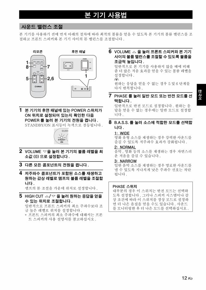
한국
어한
국어
본 기기를 사용하기 전에 먼저 아래의 절차에 따라 최적의 볼륨을 얻을 수 있도록 본 기기의 볼륨 밸런스를 조절하고 프론트 스피커와 본 기기 사이의 톤 밸런스를 조절합니다 .
1 본 기기의 후면 패널에 있는 POWER 스위치가
ON 위치로 설정되어 있는지 확인한 다음
POWER 를 눌러 본 기기의 전원을 켭니다 .
STANDBY/ON 표시등이 녹색으로 점등됩니다 .
2 VOLUME 을 눌러 본 기기의 볼륨 레벨을 최
소값 (0) 으로 설정합니다 .
3 다른 모든 콤포넌트의 전원을 켭니다 .
4 저주파수 콤포넌트가 포함된 소스를 재생하고
원하는 감상 레벨로 앰프의 볼륨 레벨을 조절합
니다 .
앰프의 톤 조절을 가운데 위치로 설정합니다 .
5 HIGH CUT / 을 눌러 원하는 응답을 얻을
수 있는 위치로 조절합니다 .
일반적으로 프론트 스피커의 최소 주파수보다 조금 높은 레벨로 위치를 설정합니다 .* 프론트 스피커의 최소 주파수에 해서는 프론
트 스피커의 사용 설명서를 참고하십시오 .
6 VOLUME 을 눌러 프론트 스피커와 본 기기
사이의 볼륨 밸런스를 조절할 수 있도록 볼륨을
조금씩 높입니다 .
일반적으로 본 기기를 사용하지 않을 때에 비해 좀 더 많은 저음 효과를 얻을 수 있는 볼륨 레벨을 설정합니다 .y원하는 응답을 얻을 수 없는 경우 5 및 6 단계를 다시 반복합니다 .
7 PHASE 를 눌러 일반 모드 또는 반전 모드를 선
택합니다 .
일반적으로 반전 모드로 설정합니다 . 원하는 응답을 얻을 수 없는 경우에는 일반 모드로 설정합니다 .
8 B.A.S.S. 를 눌러 소스에 적합한 모드를 선택합
니다 .
1: WIDE영화 유형 소스를 재생하는 경우 강력한 사운드를 즐길 수 있도록 저주파수 효과가 강화됩니다 .
2: NORMAL음악 , 영화 등의 소스를 재생하는 경우 자연스러운 저음을 즐길 수 있습니다 .
3: NARROW일반 음악 소스를 재생하는 경우 명료한 사운드를 낼 수 있도록 지나치게 낮은 주파수 신호는 차단됩니다 .
본 기기 사용법
사운드 밸런스 조절
POWER
ON
OFF
POWER
ON
OFF
POWER STANDBY SLEEP
PHASE
MEMORY
PRESET
HIGH CUT VOLUME
21 3
B.A.S.S.
1
2,6 1
리모콘 후면 패널
SUBW
STANDBY/ON
PHASE 스위치부분의 경우 이 스위치는 반전 모드는 선택하
도록 설정합니다 . 그러나 스피커 시스템이나 감상 조건에 따라 이 스위치를 정상 모드로 설정하면 더 나은 음질을 얻을 수도 있습니다 . 사운드를 모니터링한 후 더 나은 모드를 선택하십시오 .
12 Ko

본 기기 사용법
좋아하는 설정 ( 볼륨 , 고주파 차단 , 위상 및 B.A.S.S. 설정 ) 을 최 3 세트까지 본 기기에 저장할 수 있습니다 .
■설정 저장
이 절차에서는 일례로 PRESET 1 을 사용합니다 .
1 볼륨 , 고주파 차단 , 위상 및 B.A.S.S. 사이의 사
운드 밸런스를 조절합니다 (12 페이지 참조 ).
2 MEMORY 를 누릅니다 .
전면 패널의 PRESET 표시등이 깜박입니다 .
3 PRESET 1 을 누릅니다 .
PRESET 1 표시등이 점등됩니다 . 현재 설정이 PRESET 1 로 저장됩니다 .
y
• 3 단계에서 저장 번호를 누르면 이전 설정을 겹쳐씁니다 .
• PRESET을 눌러 VOLUME 컨트롤 또는 H-CUT 컨트롤을 회전하는 동안 다른 PRESET 을 누르면 효과가 없습니다 .
■설정 호출
호출하려는 PRESET(1, 2 또는 3) 을 누릅니다 .
■메모리 백업
후면 패널에서 POWER 스위치를 사용하여 본 기기의 전원을 끄더라도 본 기기를 켜면 마지막 설정이 호출됩니다 ( 마지막 메모리 기능 ).
1 주 이상 전원이 차단된 경우 설정은 지워집니다 .
슬립 타이머를 설정하면 본 기기는 120 분 후에 자동으로 기 모드로 전환됩니다 .
SLEEP 를 누릅니다 .
STANDBY/ON 표시등의 색상은 주황색으로 변경됩니다 .
SLEEP 을 다시 누르면 슬립 타이머가 취소됩니다 .
사운드 밸런스 설정 저장
POWER STANDBY SLEEP
PHASE
MEMORY
PRESET
HIGH CUT VOLUME
21 3
B.A.S.S.
H-CUT
SUBWOOFER SYSTEM NS-SW901
STANDBY/ON
STANDBY/ON PHASE
1 2 3 1 2 3
B.A.S.S. PRESET
100H
z40Hz
VOLUME100
1 1
1
2
113
리모콘 전면 패널
STANDBY/ON 표시등
-SW901
3 1 2 3
PRESET
참고
슬립 타이머 설정
POWER STANDBY SLEEP
PHASE
MEMORY
PRESET
HIGH CUT VOLUME
21 3
B.A.S.S.
SLEEP
SUBW
STANDBY/ON
13 Ko
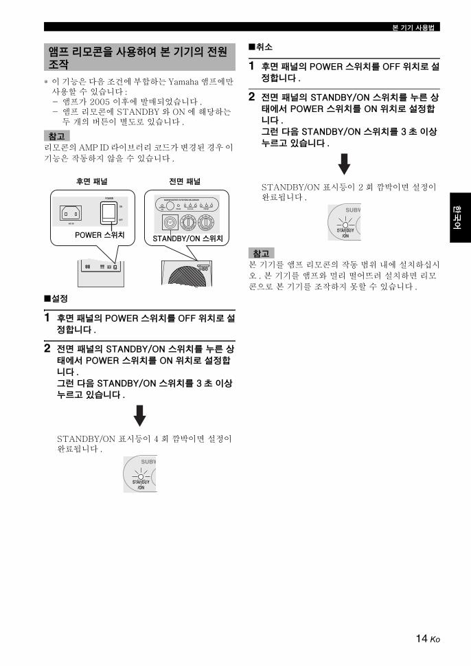
본 기기 사용법
한국
어한
국어
* 이 기능은 다음 조건에 부합하는 Yamaha 앰프에만 사용할 수 있습니다 : - 앰프가 2005 이후에 발매되었습니다 . - 앰프 리모콘에 STANDBY 와 ON 에 해당하는
두 개의 버튼이 별도로 있습니다 .
리모콘의 AMP ID 라이브러리 코드가 변경된 경우 이 기능은 작동하지 않을 수 있습니다 .
■설정
1 후면 패널의 POWER 스위치를 OFF 위치로 설
정합니다 .
2 전면 패널의 STANDBY/ON 스위치를 누른 상
태에서 POWER 스위치를 ON 위치로 설정합
니다 .
그런 다음 STANDBY/ON 스위치를 3 초 이상
누르고 있습니다 .
STANDBY/ON 표시등이 4 회 깜박이면 설정이 완료됩니다 .
■취소
1 후면 패널의 POWER 스위치를 OFF 위치로 설
정합니다 .
2 전면 패널의 STANDBY/ON 스위치를 누른 상
태에서 POWER 스위치를 ON 위치로 설정합
니다 .
그런 다음 STANDBY/ON 스위치를 3 초 이상
누르고 있습니다 .
STANDBY/ON 표시등이 2 회 깜박이면 설정이 완료됩니다 .
본 기기를 앰프 리모콘의 작동 범위 내에 설치하십시오 . 본 기기를 앰프와 멀리 떨어뜨려 설치하면 리모콘으로 본 기기를 조작하지 못할 수 있습니다 .
앰프 리모콘을 사용하여 본 기기의 전원 조작
참고
H-CUT
SUBWOOFER SYSTEM NS-SW901
STANDBY/ON
STANDBY/ON PHASE
1 2 3 1 2 3
B.A.S.S. PRESET
100H
z40Hz
VOLUME100
POWER
ON
OFF
POWER
ON
OFF
POWER 스위치 STANDBY/ON 스위치
후면 패널 전면 패널
SUBW
STANDBY/ON
참고
SUBW
STANDBY/ON
14 Ko

본 기기 사용법
본 기기의 주파수 특성
아래의 그림은 이 서브우퍼와 함께 일반 프론트 스피커 시스템을 사용하는 경우 각 컨트롤 및 주파수 특성에 한 최적의 조정을 보여 줍니다 .
■예제 .1, 10 cm 또는 13 cm 어쿠스틱 서스펜션과 함께 사용하는 경우의 양방향 시스템 프론트 스피커
NS-F901 스피커를 프론트 스피커로 사용하는 경우 설정 조정 시 참고로 다음 예제를 사용하십시오 .
■예제 .2, 20 cm 또는 25 cm 어쿠스틱 서스펜션과 함께 사용하는 경우의 양방향 시스템 프론트 스피커
* 이 도표에는 실제 주파수의 응답 특성이 정확하게 나타나 있지 않습니다 .
주파수 특성
반전 모드 ( 녹색 )
반전 모드 ( 녹색 )
20 50 100 200 500Hz40
50
60
70
80
90
dB
H-CUT 140 Hz
주파수 응답 그래프 *
(H-CUT) (VOLUME)
H-CUT
140H
z40Hz
VOLUME100
(PHASE)
OOFER SYSTEM S
PHASE
1
20 50 100 200 500Hz40
50
60
70
80
90
dB
NS-SW901 (H-CUT 60 - 70 Hz)
프론트 스피커
주파수 응답 그래프 *
(H-CUT) (VOLUME)
H-CUT
140H
z40Hz
VOLUME100
OOFER SYSTEM S
PHASE
1
(PHASE)
20 50 100 200 500Hz40
50
60
70
80
90
dB
NS-SW901 (H-CUT 50 - 60Hz)
프론트 스피커
주파수 응답 그래프 *
15 Ko

한국
어한
국어
1988 년 , Yamaha 에서는 강력한 고음질 저음을 재생하기 위해 YST (Yamaha Active Servo Technology) 를 사용하는 스피커 시스템을 개발했습니다 . 이 기술에서는 앰프와 스피커를 직접 연결하므로 정확한 신호 전송 및 정밀한 스피커 제어가 가능합니다 .
이 기술의 경우 앰프의 네거티브 임피던스 드라이브로 제어되는 스피커 기기와 , 캐비넷 용량 볼륨과 포트 간에 생성되는 공명을 사용하므로 표준 베이스 리플렉스 방법에 비해 더 반향감 있는 에너지를 생성합니다 (“에어 우퍼” 개념 ). 이를 통해 종래의 방식에 비해 훨씬 작은 캐비넷에서 저음을 재생할 수 있습니다 .
Yamaha에서 새로 개발한 Advanced YST II에서는 다수의 미세 조정 항목이 Yamaha Active Servo Technology 에 추가되었으므로 앰프와 스피커를 더 효과적으로 제어할 수 있습니다. 앰프 관점에서 볼 때 사운드 주파수에 따라 스피커 임피던스가 변경되었습니다 . Yamaha 에서는 안정적인 성능을 제공하고 맑은 저음을 재생할 수 있도록 네거티브 임피던스와 정전류 드라이브가 함께 조합된 회로 디자인을 새로 개발했습니다 .
Advanced Yamaha Active Servo Technology II
높은 진폭 저음 포트
캐비넷
고급 임피던스 컨버터
액티브 서보 프로세싱
앰프
낮은 진폭 신호
에어 우퍼( 헬름홀쯔 공명기 )
신호
16 Ko

본 기기가 제 로 작동하지 않을 때는 아래 차트를 참고하십시오 . 해당 문제가 아래 차트에 없거나 아래의 설명이 도움이 되지 않으면 전원 코드를 분리하고 공인 Yamaha 리점 또는 서비스 센터에 문의하십시오 .
• 5~15 분간 과도한 레벨의 신호가 본 기기에 입력되는 경우 본 기기의 스피커 및 파워 앰프의 손상 위험을 알려주기 위해 POWER 표시등이 깜박이기 시작합니다 . 신호 입력이 5 분 이상 지속되면 본 기기는 자동으로 기 모드로 전환됩니다 .
• 막 한 양의 신호가 입력되는 경우 본 기기의 전원은 즉시 꺼집니다 . 본 기기의 전원을 다시 켜려면 전면 패널에서 STANDBY/ON 스위치를 누르십시오 .
문제 해결
문제 원인 해결책
STANDBY/ON 스위치를 눌러도 전원이 공급되지 않습니다 .
전원 플러그가 안정적으로 연결되어 있지 않습니다 .
전원 플러그를 안정적으로 연결하십시오 .
POWER 스위치가 OFF 위치로 설정되어 있습니다 .
POWER 스위치를 ON 위치로 설정하십시오 .
사운드가 출력되지 않습니다 . 볼륨이 최소값 (0) 으로 설정되어 있습니다 .
볼륨을 높이십시오 .
스피커 케이블이 안정적으로 연결되어 있지 않습니다 .
스피커 케이블을 안정적으로 연결하십시오 .
앰프에서 나오는 신호가 너무 작습니다 . 앰프에 연결된 콤포넌트 또는 앰프의 볼륨을 높이십시오 .
앰프의 서브우퍼 출력 터미널에서 신호가 출력되지 않습니다 .
앰프의 스피커 모드 설정을 확인하십시오 .
사운드 레벨이 너무 낮습니다 . 스피커 케이블이 올바르게 연결되어 있지 않습니다 .
스피커 케이블을 올바르게 연결합니다. 즉 , L( 왼쪽 ) 은 L 에 , R( 오른쪽 ) 은 R 에 , “+”는 “+”에 , “-”는 “-”에 연결합니다 .
위상 설정이 올바르지 않습니다 . 위상을 다른 위치로 설정하십시오 .
저음 주파수가 거의 없는 소스 사운드를 재생했습니다 .
저음 주파수가 있는 소스 사운드를 재생하십시오 .H-CUT 을 높은 위치로 설정하십시오 .
정재파에 의해 영향을 받습니다 . 서브우퍼 위치를 변경하거나 각도를 변경하십시오 .
리모콘이 작동하지 않습니다 . 거리나 각도가 잘못되었습니다 . 리모콘은 전면 패널로부터 최 6 m 내의 범위와 30 도 이하의 각도에서 사용하십시오 .
직사광선이나 조명 ( 인버터 형태의 형광등 등 ) 이 본 기기의 리모콘 센서에 비춰지고 있습니다 .
본 기기의 위치를 바꾸십시오 .
건전지가 소모되었습니다 . 건전지를 모두 교체하십시오 .
본 기기의 리모콘 신호 수신기와 리모콘 사이에 장애물이 있습니다 .
장애물을 제거하십시오 .
앰프 리모콘으로 본 기기 전원이 켜지지 않습니다 . ( “앰프 리모콘을 사용하여 본 기기의 전원 조작” 설정 시 )
거리나 각도가 잘못되었습니다 . 본 기기를 앰프 리모콘의 작동 범위 내에 설치하십시오 .
차단기가 내려갔습니다 . 높은 레벨의 신호가 본 기기에 입력될 때 본 기기는 다량의 전기를 소모합니다 .
본 기기에 연결된 앰프 등의 볼륨을 줄이거나 사용하지 않는 다른 기기의 전원을 끄십시오 .
포트 속에 물체가 빠졌습니다 . 물체를 제거하려고 하지 마십시오 . 물체를 제거하려다가 오기능을 야기할 수 있습니다 .
공인 Yamaha 리점이나 서비스 센터에 연락하십시오 .
참고
17 Ko

한국
어한
국어
유형 ................. Advanced Yamaha Active Servo Technology II
드라이버 ......................................... 25 cm 콘 우퍼자력 차단식
앰프 출력 (100 Hz, 4 ohms, 10% THD) .... 600 W
주파수 응답 ................................ 18 Hz - 160 Hz
전원미국과 캐나다 모델................AC 120 V, 60 Hz영국과 유럽 모델 ...................AC 230 V, 50 Hz오스트레일리아 모델..............AC 240 V, 50 Hz아시아 및 일반 모델...... AC 110/120/220/230-240 V, 50/60 Hz한국 모델...............................AC 220 V, 60 Hz중국 모델...............................AC 220 V, 50 Hz
소비 전력.................................................... 180 W
기 소비 전력............................................. 0.5 W
크기 (W x H x D)
........................... 410 mm x 457 mm x 462 mm
무게 ........................................................... 32 kg
본 제품의 사양은 예고 없이 변경될 수 있습니다 .
사양
18 Ko


Printed in Indonesia ZH67610© 2013 Yamaha Corporation