openfoam을 활용한 산업용 연소기 해석 연구...
TRANSCRIPT

OpenFOAM을 활용한 산업용 연소기
해석 연구 현황
Sep. 10-11th 2015
대전 호텔 ICC, Daejeon, Korea
허 강열
Pohang University of Science and Technology
2015 4th OpenFOAM Korea Users’ Community Conference
(4th OKUCC)

Introduction
Most industrial combustion devices operate in the regime of turbulent combustion
Diesel engine
Gas turbine Pulverized coal power plant
CFD analysis of turbulent combustion is a crucial design process
to improve performance of practical combustion devices
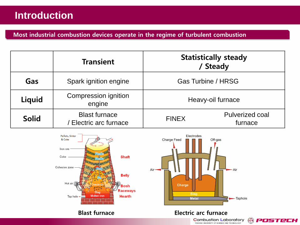
Introduction
Transient Statistically steady
/ Steady
Gas Spark ignition engine Gas Turbine / HRSG
Liquid Compression ignition
engine Heavy-oil furnace
Solid Blast furnace
/ Electric arc furnace FINEX
Pulverized coal
furnace
Most industrial combustion devices operate in the regime of turbulent combustion
Blast furnace Electric arc furnace
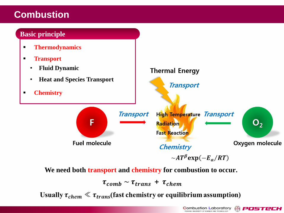
We need both transport and chemistry for combustion to occur.
Thermodynamics
Transport
Chemistry
• Fluid Dynamic
• Heat and Species Transport
Basic principle
Combustion
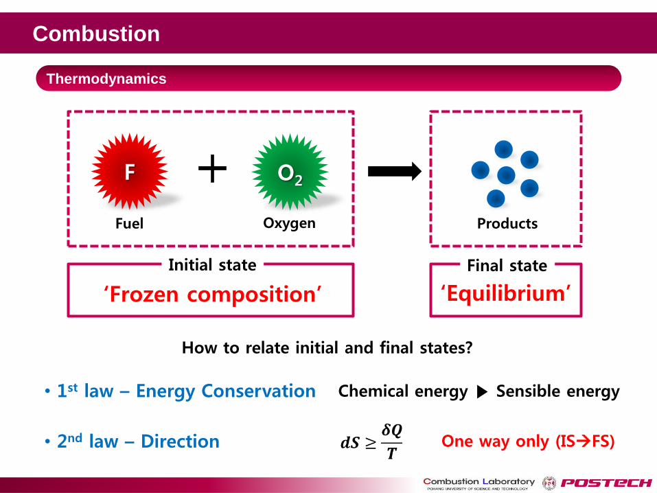
Thermodynamics
F O2
Initial state
‘Frozen composition’ ‘Equilibrium’
Final state
Fuel Oxygen Products
• 1st law – Energy Conservation Chemical energy ▶ Sensible energy
• 2nd law – Direction
How to relate initial and final states?
One way only (ISFS)
Combustion
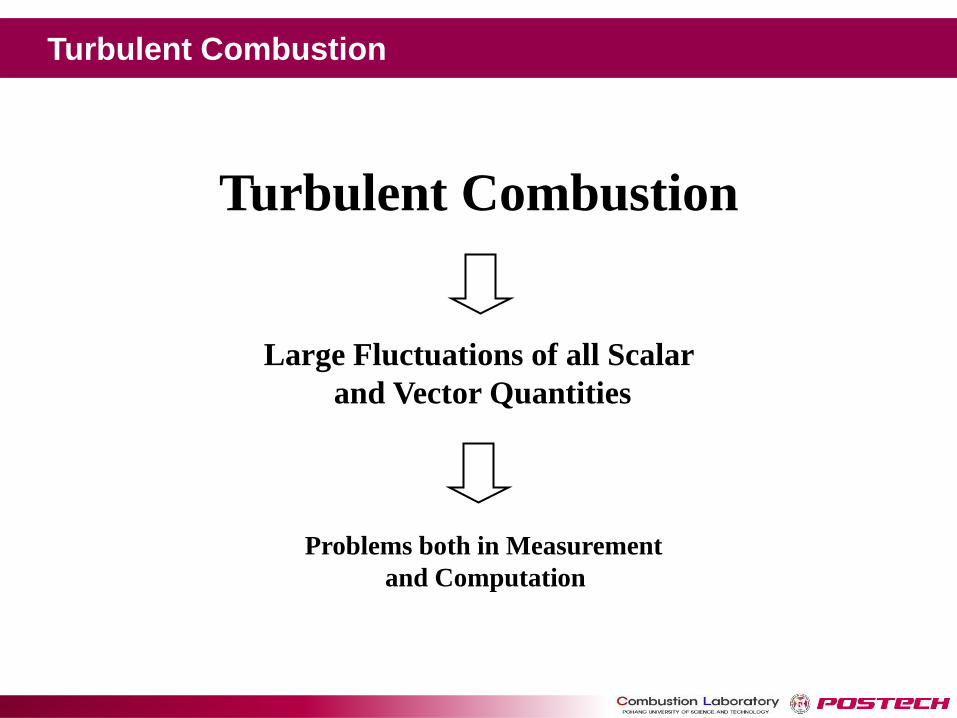
Large Fluctuations of all Scalar
and Vector Quantities
Problems both in Measurement
and Computation
Turbulent Combustion
Turbulent Combustion

Governing equations
v 0k
kt x
vv vi ik i
k i k
k i
pg
t x x x
v wi ik
k k
k i iYY Jt x x
1
1 1[ ( )v ]
Ni
i
ik
k
k k i k
Yp hhh h
t x t x x Sc x
p RT
( , , )ih h Y p TNonlinear Convection Term
Nonlinear Reaction Term
Favre Averaged Conservation Eqs with Nonlinear Terms
Turbulent Combustion
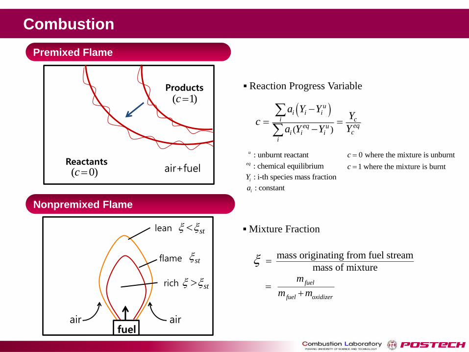
Premixed Flame
Nonpremixed Flame
air air
flame
lean
rich
fuel
st
st
st
Mixture Fraction
mass originating from fuel stream
mass of mixture
fuel
fuel oxidizer
m
m m
( 0)c
( 1)c
Reaction Progress Variable
( )
ui i i
i ceqeq u
ci i ii
a Y YY
cYa Y Y
0 where the mixture is unburnt
1 where the mixture is burnt
c
c
: unburnt reactantu
: chemical equilibriumeq
: i-th species mass fractioniY
: constantia
Products
Reactants air+fuel
Combustion
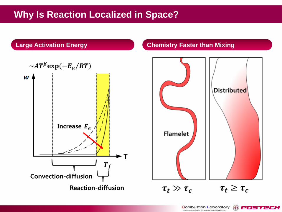
Convection-diffusion
Reaction-diffusion
Large Activation Energy Chemistry Faster than Mixing
Why Is Reaction Localized in Space?
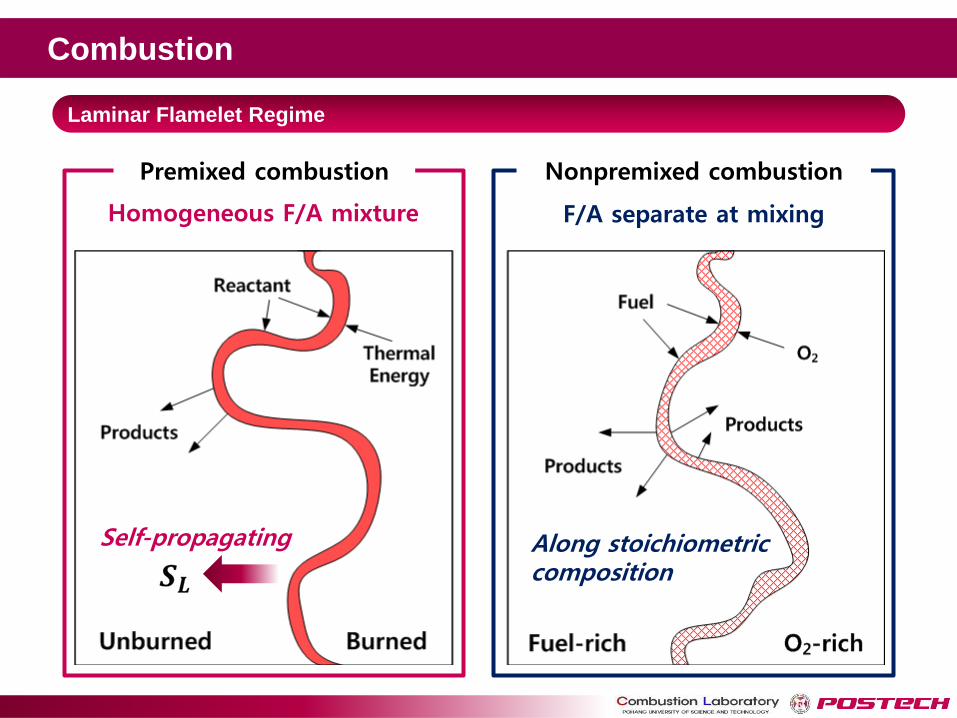
Laminar Flamelet Regime
Premixed combustion Nonpremixed combustion
Homogeneous F/A mixture F/A separate at mixing
Self-propagating Along stoichiometric composition
Combustion

Turbulent Nonpremixed
Flames
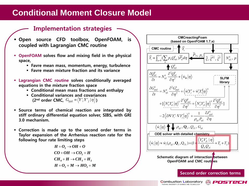
Conditional Moment Closure Model
Schematic diagram of interaction between OpenFOAM and CMC routines
Open source CFD toolbox, OpenFOAM, is coupled with Lagrangian CMC routine
OpenFOAM solves flow and mixing field in the physical space,
Favre mean mass, momentum, energy, turbulence Favre mean mixture fraction and its variance
Lagrangian CMC routine solves conditionally averaged
equations in the mixture fraction space Conditional mean mass fractions and enthalpy Conditional variances and covariances (2nd order CMC, )
Source terms of chemical reaction are integrated by
stiff ordinary differential equation solver, SIBS, with GRI 3.0 mechanism.
Correction is made up to the second order terms in Taylor expansion of the Arrhenius reaction rate for the following four rate limiting steps
2
2
4 3 2
2 2
H O OH O
CO OH CO H
CH H CH H
H O M HO M
Implementation strategies
' ' |i jij LG Y Y
Second order correction terms
Basic Flame - Sandia Flame D & E
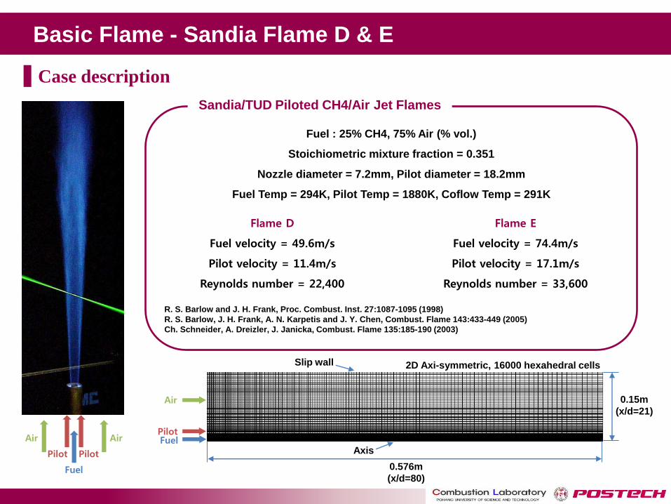
Fuel : 25% CH4, 75% Air (% vol.)
Stoichiometric mixture fraction = 0.351
Nozzle diameter = 7.2mm, Pilot diameter = 18.2mm
Fuel Temp = 294K, Pilot Temp = 1880K, Coflow Temp = 291K
R. S. Barlow and J. H. Frank, Proc. Combust. Inst. 27:1087-1095 (1998)
R. S. Barlow, J. H. Frank, A. N. Karpetis and J. Y. Chen, Combust. Flame 143:433-449 (2005)
Ch. Schneider, A. Dreizler, J. Janicka, Combust. Flame 135:185-190 (2003)
Sandia/TUD Piloted CH4/Air Jet Flames
Flame D
Fuel velocity = 49.6m/s
Pilot velocity = 11.4m/s
Reynolds number = 22,400
Flame E
Fuel velocity = 74.4m/s
Pilot velocity = 17.1m/s
Reynolds number = 33,600
Pilot
Air
Fuel
Air
Pilot
Slip wall
Axis
0.15m
(x/d=21)
0.576m
(x/d=80)
Fuel Pilot
Air
2D Axi-symmetric, 16000 hexahedral cells
Case description
Basic Flame - Sandia Flame D & E
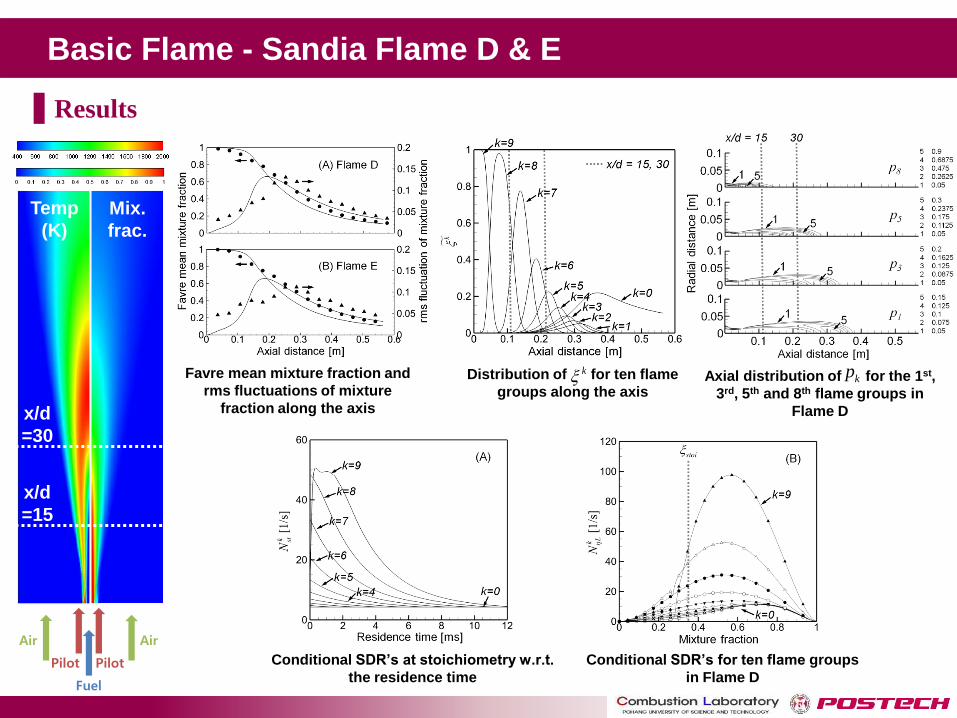
Distribution of for ten flame
groups along the axis Axial distribution of for the 1st,
3rd, 5th and 8th flame groups in
Flame D
k kp
Temp
(K)
Mix.
frac.
x/d
=30
x/d
=15
Favre mean mixture fraction and
rms fluctuations of mixture
fraction along the axis
Conditional SDR’s at stoichiometry w.r.t.
the residence time
Conditional SDR’s for ten flame groups
in Flame D Pilot
Air
Fuel
Air
Pilot
Results
Basic Flame - Sandia Flame D & E
Temp
(K)
Mix.
frac.
x/d
=30
x/d
=15
Pilot
Air
Fuel
Air
Pilot
Results
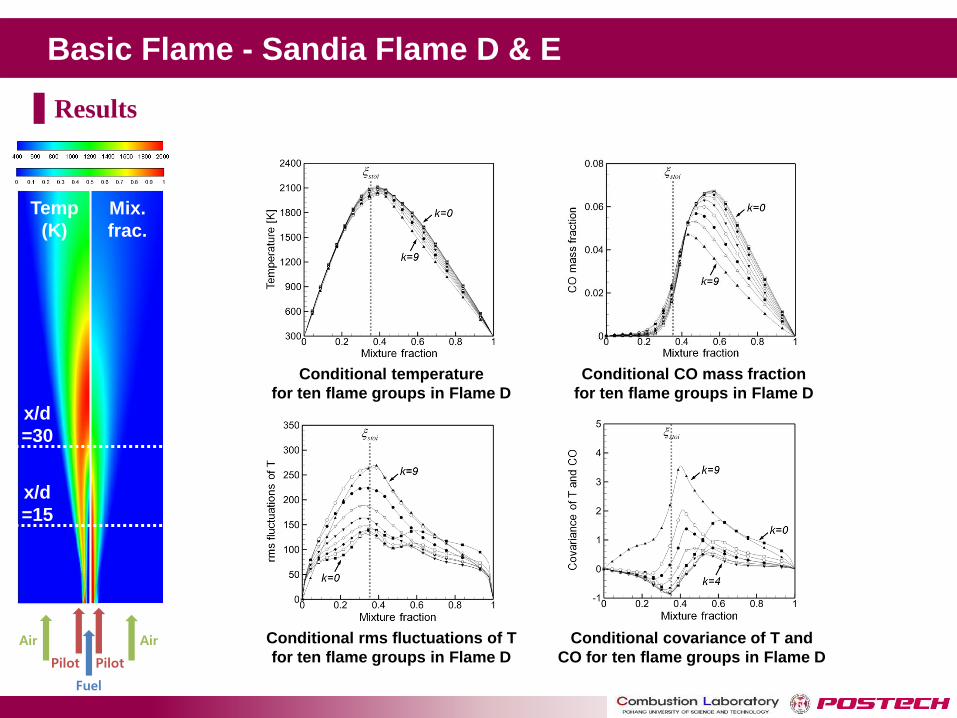
Conditional rms fluctuations of T
for ten flame groups in Flame D
Conditional covariance of T and
CO for ten flame groups in Flame D
Conditional temperature
for ten flame groups in Flame D
Conditional CO mass fraction
for ten flame groups in Flame D

Basic Flame - Sandia Flame D & E
Temp
(K)
Mix.
frac.
x/d
=30
x/d
=15
Measured and predicted T, conditional mass fractions at x/d=15, 30
in Flame D and E (symbols, measurement; lines, prediction)
Results
Pilot
Air
Fuel
Air
Pilot
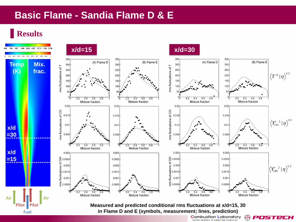
x/d=15 x/d=30
Basic Flame - Sandia Flame D & E
Temp
(K)
Mix.
frac.
x/d
=30
x/d
=15
Measured and predicted conditional rms fluctuations at x/d=15, 30
in Flame D and E (symbols, measurement; lines, prediction)
1/22' |T
1/22 |COY
1/22 |OHY
Results
Pilot
Air
Fuel
Air
Pilot
x/d=15 x/d=30
Basic Flame - Sandia Flame D & E
Temp
(K)
Mix.
frac.
x/d
=30
x/d
=15
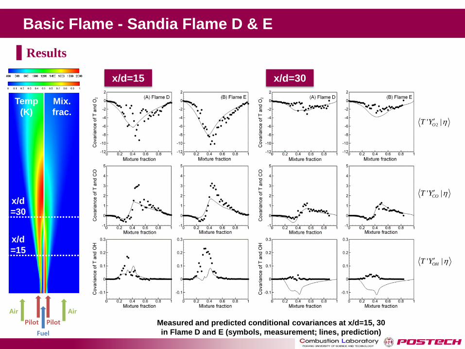
Measured and predicted conditional covariances at x/d=15, 30
in Flame D and E (symbols, measurement; lines, prediction)
' |COT Y
' |OHT Y
2' |OT Y
Results
Pilot
Air
Fuel
Air
Pilot
x/d=15 x/d=30
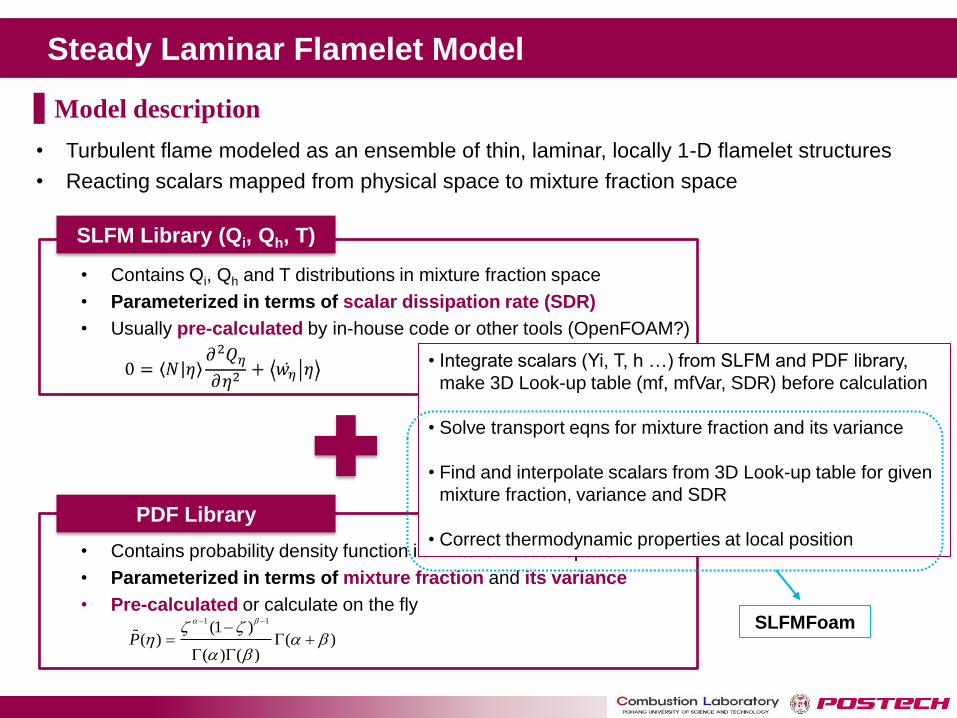
Steady Laminar Flamelet Model
• Turbulent flame modeled as an ensemble of thin, laminar, locally 1-D flamelet structures
• Reacting scalars mapped from physical space to mixture fraction space
Model description
• Contains Qi, Qh and T distributions in mixture fraction space
• Parameterized in terms of scalar dissipation rate (SDR)
• Usually pre-calculated by in-house code or other tools (OpenFOAM?)
• Contains probability density function in mixture fraction space
• Parameterized in terms of mixture fraction and its variance
• Pre-calculated or calculate on the fly 1 1(1 )
( ) ( )( ) ( )
P
SLFM Library (Qi, Qh, T)
PDF Library
• Integrate scalars (Yi, T, h …) from SLFM and PDF library,
make 3D Look-up table (mf, mfVar, SDR) before calculation
• Solve transport eqns for mixture fraction and its variance
• Find and interpolate scalars from 3D Look-up table for given
mixture fraction, variance and SDR
• Correct thermodynamic properties at local position
SLFMFoam
Industrial Furnace - Heat Recovery Steam Generator
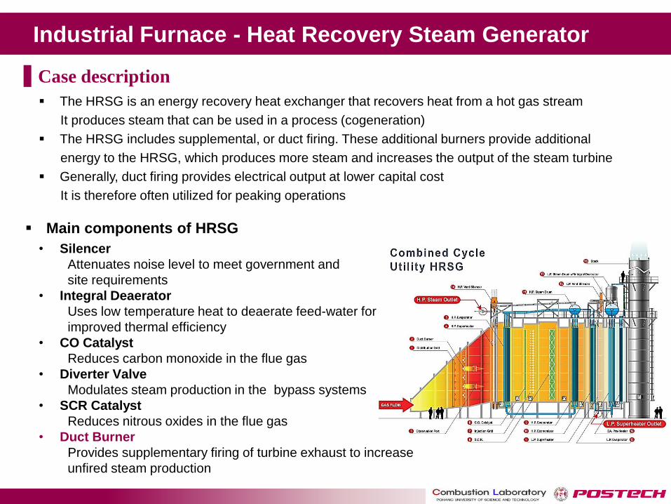
Main components of HRSG
• Silencer
Attenuates noise level to meet government and
site requirements
• Integral Deaerator
Uses low temperature heat to deaerate feed-water for
improved thermal efficiency
• CO Catalyst
Reduces carbon monoxide in the flue gas
• Diverter Valve
Modulates steam production in the bypass systems
• SCR Catalyst
Reduces nitrous oxides in the flue gas
• Duct Burner
Provides supplementary firing of turbine exhaust to increase
unfired steam production
The HRSG is an energy recovery heat exchanger that recovers heat from a hot gas stream
It produces steam that can be used in a process (cogeneration)
The HRSG includes supplemental, or duct firing. These additional burners provide additional
energy to the HRSG, which produces more steam and increases the output of the steam turbine
Generally, duct firing provides electrical output at lower capital cost
It is therefore often utilized for peaking operations
Case description

Industrial Furnace - Heat Recovery Steam Generator
Perforated wall and Burner Computational mesh
Inlet
Fuel nozzle
Description Specification
Fuel Natural gas
Combustion model Steady Laminar Flamelet Model
Turbulence model Realizable k-ε
Discretization 2nd order upwind
Mesh About 7,000,000 cells (1st stage)
About 9,000,000 cells (2nd stage)
Case description
Industrial Furnace - Heat Recovery Steam Generator
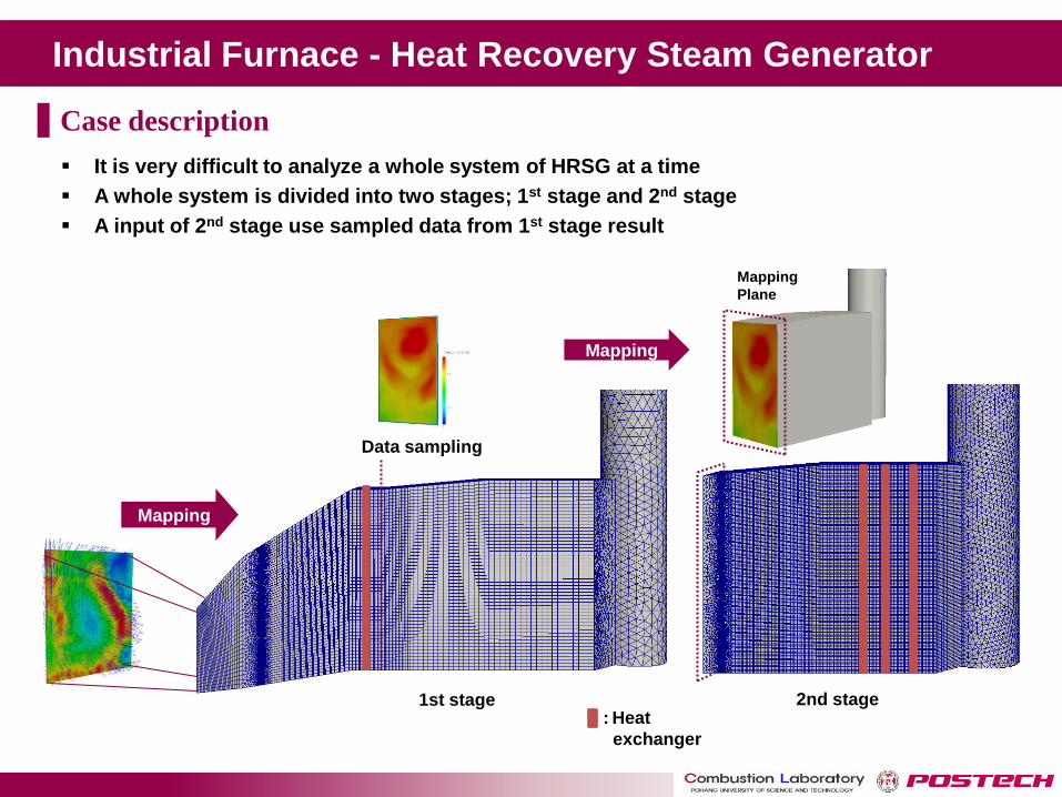
1st stage 2nd stage
Data sampling
Mapping
Plane
Mapping
Mapping
: Heat
exchanger
It is very difficult to analyze a whole system of HRSG at a time
A whole system is divided into two stages; 1st stage and 2nd stage
A input of 2nd stage use sampled data from 1st stage result
Case description
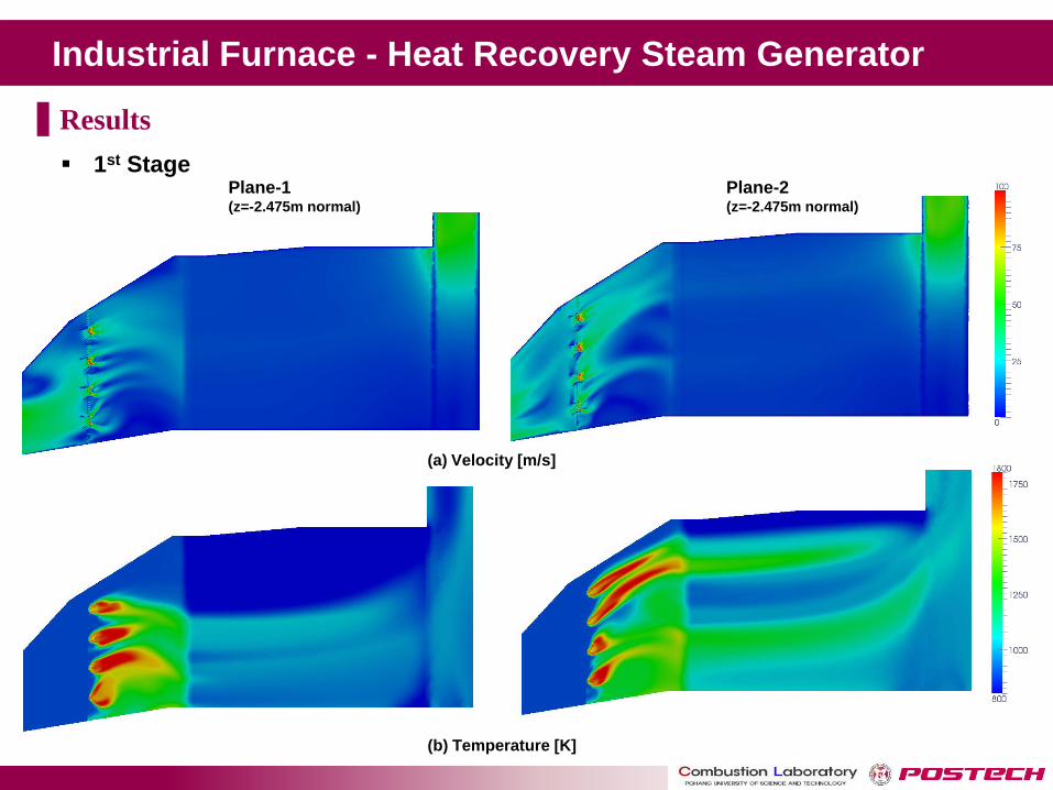
Industrial Furnace - Heat Recovery Steam Generator
1st Stage Plane-1 (z=-2.475m normal)
Plane-2 (z=-2.475m normal)
(a) Velocity [m/s]
(b) Temperature [K]
Results
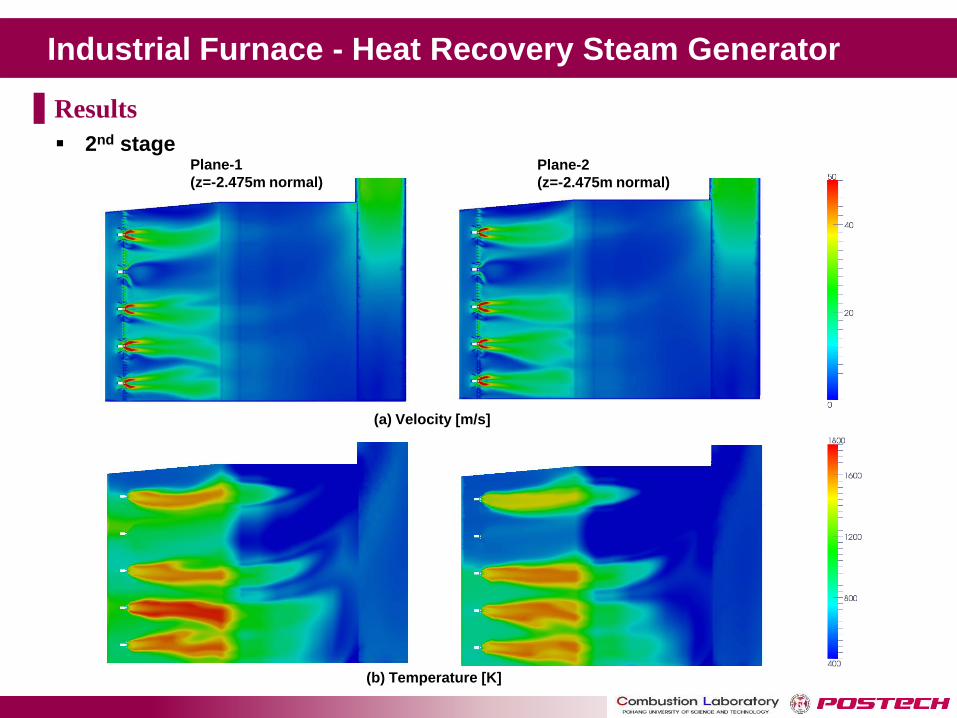
Industrial Furnace - Heat Recovery Steam Generator
2nd stage
(b) Temperature [K]
Plane-1
(z=-2.475m normal)
Plane-2
(z=-2.475m normal)
(a) Velocity [m/s]
Results

Industrial Furnace - Heat Recovery Steam Generator
Case Fluent OpenFOAM Measured
/ Performance Ratio
Units Outlet Outlet Outlet Fluent OpenFOAM
Temperature K 385.95 453.275 401.85 0.96 1.12
Composition
O2
mass f
racti
on
9.08E-02 8.98E-02 9.71E-02 0.94 0.92
CO2 8.99E-02 9.75E-02 8.60E-02 1.05 1.13
H2O 9.97E-02 9.28E-02 9.34E-02 1.07 0.99
N2 7.07E-01 7.12E-01 7.09E-01 1.00 1.00
AR 1.18E-02 1.16E-02 1.19E-02 0.99 0.97
CO ppm vd
@actual O2
21.9 33.2 44.32 0.49 0.75
NO 5.68 29.5 21.64 0.26 1.36
Comparison with the result for FLUENT
Results
Turbulent Partially Premixed
Flames
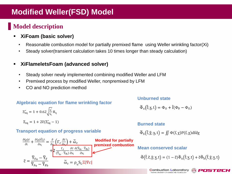
Modified Weller(FSD) Model
• Reasonable combustion model for partially premixed flame using Weller wrinkling factor(Xi)
• Steady solver(transient calculation takes 10 times longer than steady calculation)
Transport equation of progress variable
Algebraic equation for flame wrinkling factor
Mean conserved scalar
Unburned state
Burned state
Modified for partially
premixed combustion
• Steady solver newly implemented combining modified Weller and LFM
• Premixed process by modified Weller, nonpremixed by LFM
• CO and NO prediction method
XiFoam (basic solver)
XiFlameletsFoam (advanced solver)
Model description
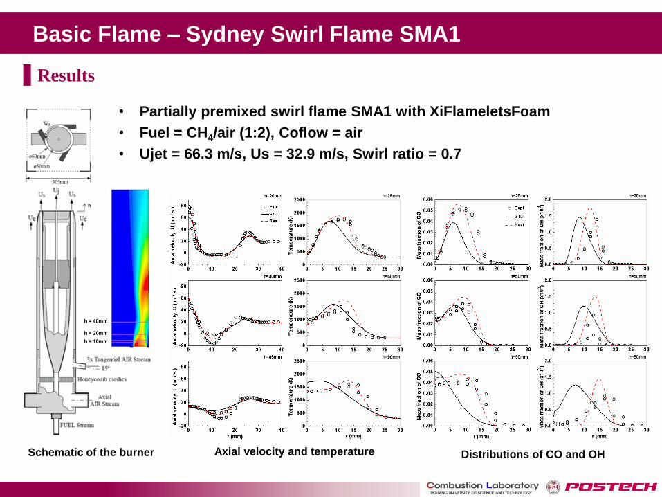
Basic Flame – Sydney Swirl Flame SMA1
Schematic of the burner Axial velocity and temperature Distributions of CO and OH
Results
• Partially premixed swirl flame SMA1 with XiFlameletsFoam
• Fuel = CH4/air (1:2), Coflow = air
• Ujet = 66.3 m/s, Us = 32.9 m/s, Swirl ratio = 0.7
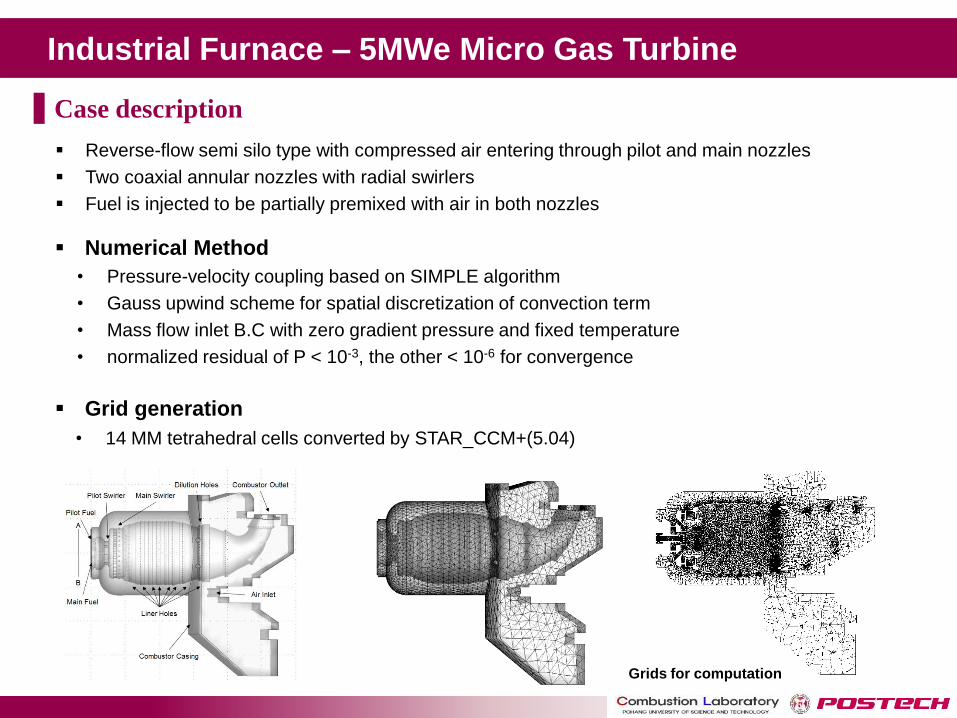
Industrial Furnace – 5MWe Micro Gas Turbine
Numerical Method
Grid generation
Grids for computation
Reverse-flow semi silo type with compressed air entering through pilot and main nozzles
Two coaxial annular nozzles with radial swirlers
Fuel is injected to be partially premixed with air in both nozzles
• Pressure-velocity coupling based on SIMPLE algorithm
• Gauss upwind scheme for spatial discretization of convection term
• Mass flow inlet B.C with zero gradient pressure and fixed temperature
• normalized residual of P < 10-3, the other < 10-6 for convergence
• 14 MM tetrahedral cells converted by STAR_CCM+(5.04)
Case description
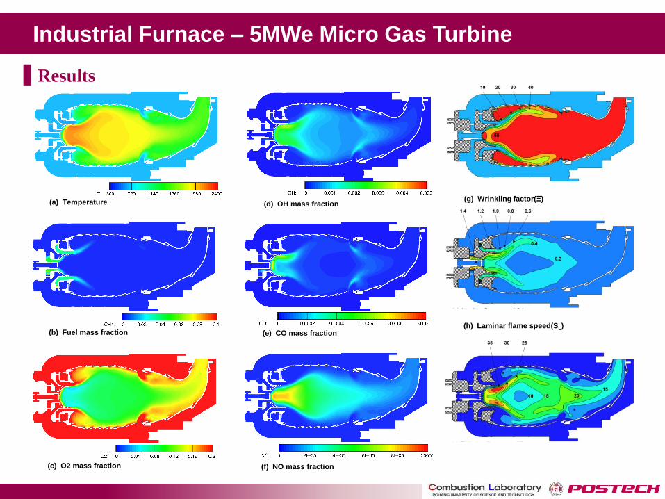
Industrial Furnace – 5MWe Micro Gas Turbine
(a) Temperature
(f) NO mass fraction
(e) CO mass fraction
(g) Wrinkling factor(Ξ)
(b) Fuel mass fraction
(c) O2 mass fraction
(d) OH mass fraction
(h) Laminar flame speed(SL)
Results
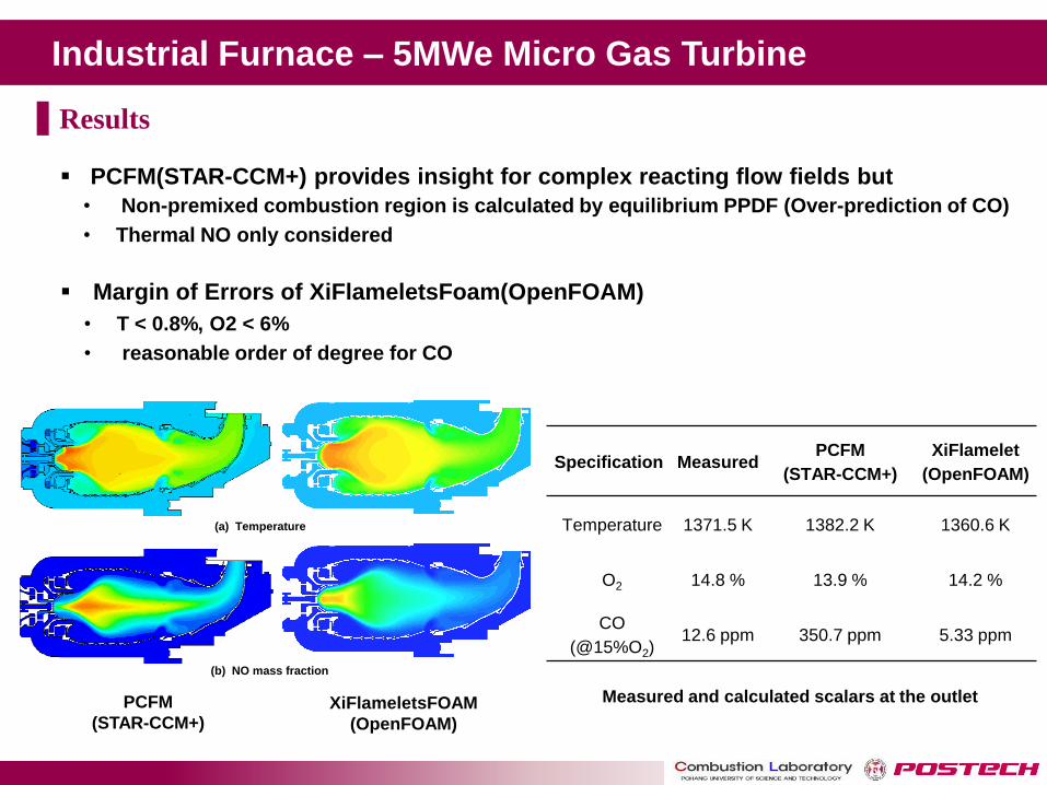
Industrial Furnace – 5MWe Micro Gas Turbine
PCFM
(STAR-CCM+) XiFlameletsFOAM
(OpenFOAM)
(a) Temperature
(b) NO mass fraction
Specification Measured PCFM
(STAR-CCM+)
XiFlamelet
(OpenFOAM)
Temperature 1371.5 K 1382.2 K 1360.6 K
O2 14.8 % 13.9 % 14.2 %
CO
(@15%O2) 12.6 ppm 350.7 ppm 5.33 ppm
Measured and calculated scalars at the outlet
PCFM(STAR-CCM+) provides insight for complex reacting flow fields but
Margin of Errors of XiFlameletsFoam(OpenFOAM)
• Non-premixed combustion region is calculated by equilibrium PPDF (Over-prediction of CO)
• Thermal NO only considered
• T < 0.8%, O2 < 6%
• reasonable order of degree for CO
Results
Spray Combustion Modeling
Spray Combustion Modeling
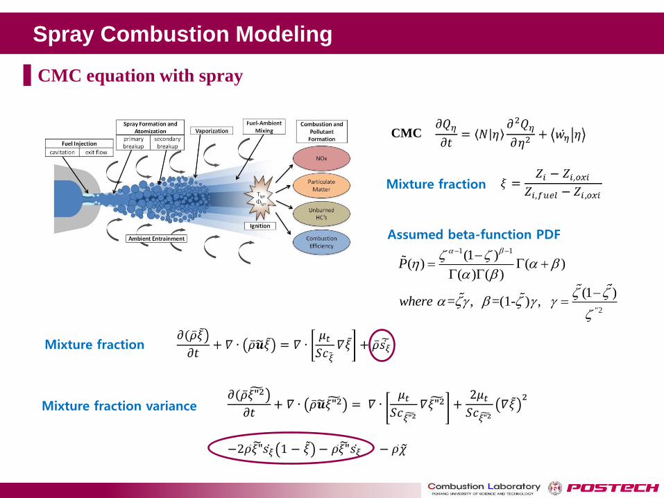
CMC equation with spray
Assumed beta-function PDF
Mixture fraction
Mixture fraction variance
Mixture fraction
CMC
1 1(1 )( ) ( )
( ) ( )P
"2
(1 ) = , =(1- ) , where
ECN
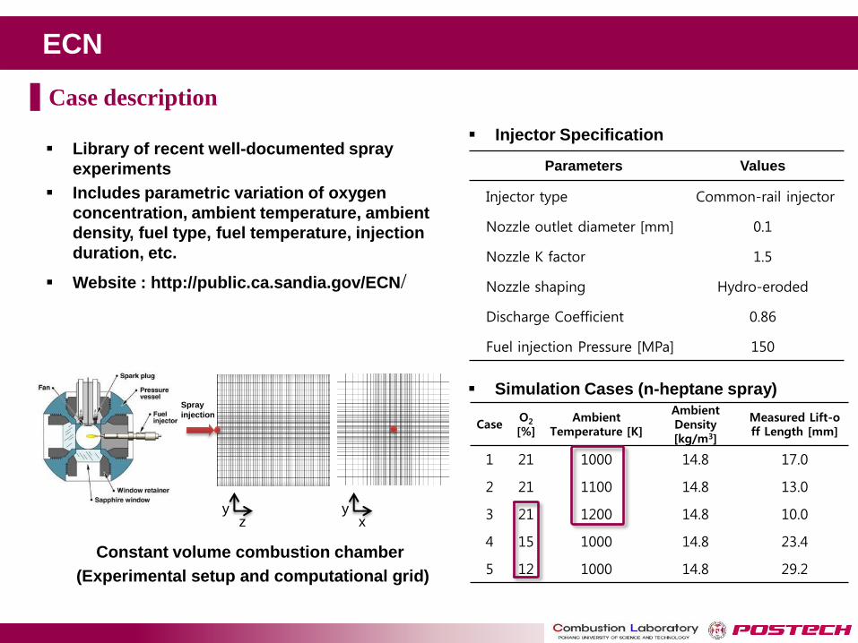
Library of recent well-documented spray
experiments
Includes parametric variation of oxygen
concentration, ambient temperature, ambient
density, fuel type, fuel temperature, injection
duration, etc.
Website : http://public.ca.sandia.gov/ECN/
Injector Specification
Constant volume combustion chamber
(Experimental setup and computational grid)
Parameters Values
Injector type Common-rail injector
Nozzle outlet diameter [mm] 0.1
Nozzle K factor 1.5
Nozzle shaping Hydro-eroded
Discharge Coefficient 0.86
Fuel injection Pressure [MPa] 150
x y
Spray
injection
z y
Case O2 [%]
Ambient Temperature [K]
Ambient Density [kg/m3]
Measured Lift-off Length [mm]
1 21 1000 14.8 17.0
2 21 1100 14.8 13.0
3 21 1200 14.8 10.0
4 15 1000 14.8 23.4
5 12 1000 14.8 29.2
Simulation Cases (n-heptane spray)
Case description
ECN
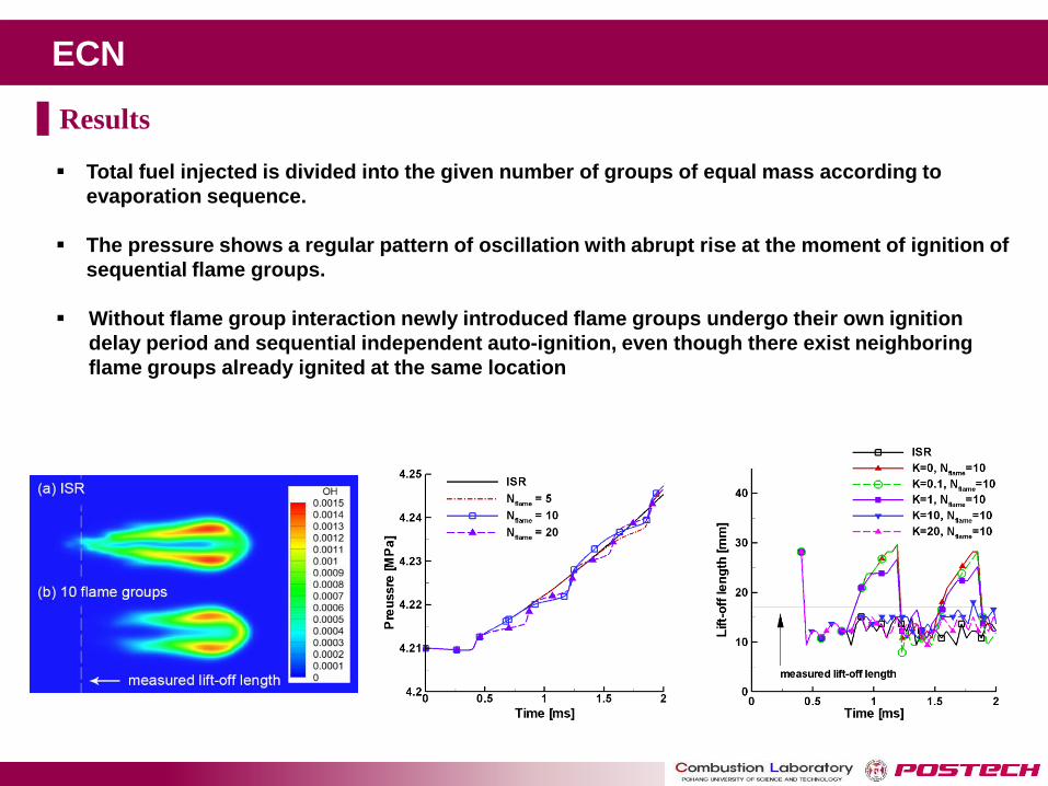
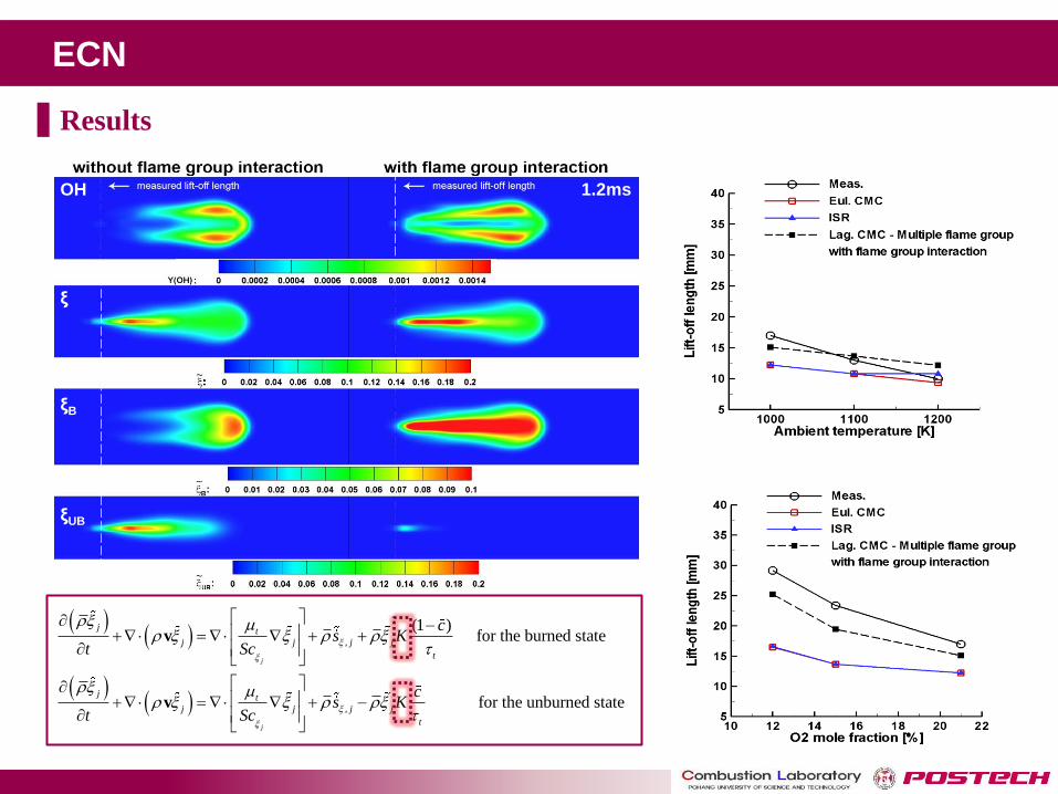
Total fuel injected is divided into the given number of groups of equal mass according to
evaporation sequence.
The pressure shows a regular pattern of oscillation with abrupt rise at the moment of ignition of
sequential flame groups.
Without flame group interaction newly introduced flame groups undergo their own ignition
delay period and sequential independent auto-ignition, even though there exist neighboring
flame groups already ignited at the same location
Results

ECN
Case Lift-off length [mm]
Measured 17.0
ISR 12.2
K=0 (without flame
group interaction) 7.9 / 29.6
K=0.1 7.9 / 29.6
K=1 9.3 / 25.2
K=10 15.1
K=20 13.6
,
,
(1 ) for the burned state
for the unburned state
j
j
j t
j j j j
t
j t
j j j j
t
cs K
t Sc
cs K
t Sc
v
v
1.2ms OH
ξ
ξB
ξUB
Results
ECN
,
,
(1 ) for the burned state
for the unburned state
j
j
j t
j j j j
t
j t
j j j j
t
cs K
t Sc
cs K
t Sc
v
v
1.2ms OH
ξ
ξB
ξUB
Results
Diesel Engine – ERC
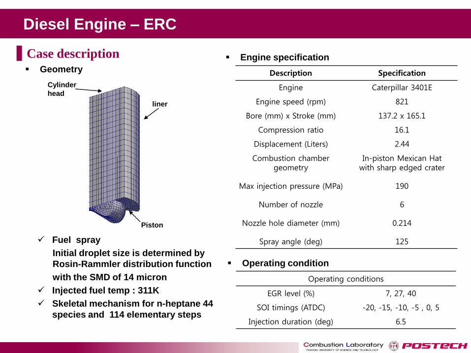
Operating conditions
EGR level (%) 7, 27, 40
SOI timings (ATDC) -20, -15, -10, -5 , 0, 5
Injection duration (deg) 6.5
Cylinder
head
liner
Piston
Fuel spray
Initial droplet size is determined by
Rosin-Rammler distribution function
with the SMD of 14 micron
Injected fuel temp : 311K
Skeletal mechanism for n-heptane 44
species and 114 elementary steps
Operating condition
Geometry
Case description
Description Specification
Engine Caterpillar 3401E
Engine speed (rpm) 821
Bore (mm) x Stroke (mm) 137.2 x 165.1
Compression ratio 16.1
Displacement (Liters) 2.44
Combustion chamber geometry
In-piston Mexican Hat with sharp edged crater
Max injection pressure (MPa) 190
Number of nozzle 6
Nozzle hole diameter (mm) 0.214
Spray angle (deg) 125
Engine specification

Diesel Engine – ERC
Conditional mean temperature and scalar dissipation rate
with respect to the mixture fraction Spatial distributions of the temperature
and mean mixture fraction
Pressure trace w.r.t different EGR (%)
Results
Diesel Engine – D1
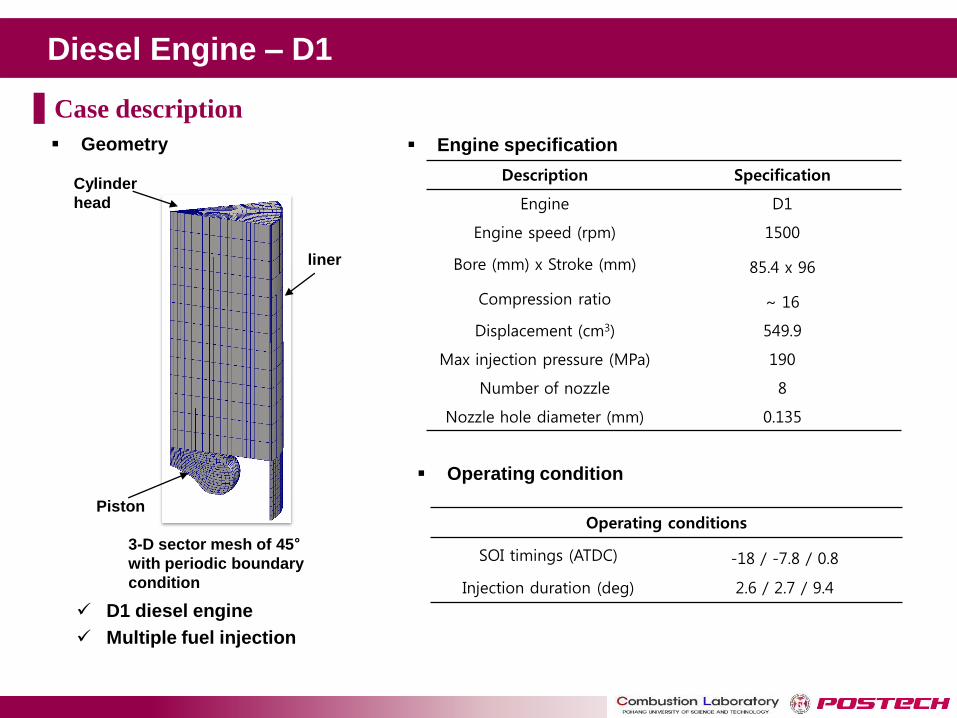
D1 diesel engine
Multiple fuel injection
Description Specification
Engine D1
Engine speed (rpm) 1500
Bore (mm) x Stroke (mm) 85.4 x 96
Compression ratio ~ 16
Displacement (cm3) 549.9
Max injection pressure (MPa) 190
Number of nozzle 8
Nozzle hole diameter (mm) 0.135
Operating conditions
SOI timings (ATDC) -18 / -7.8 / 0.8
Injection duration (deg) 2.6 / 2.7 / 9.4
Cylinder
head
liner
Piston
3-D sector mesh of 45° with periodic boundary
condition
Geometry Engine specification
Operating condition
Case description
Diesel Engine - D1
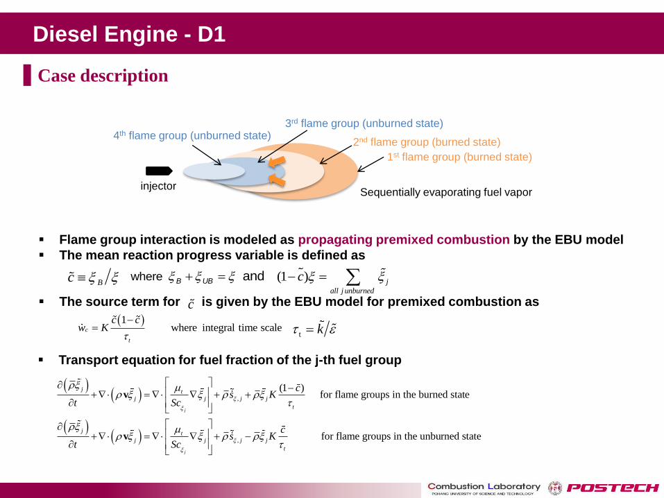
Flame group interaction is modeled as propagating premixed combustion by the EBU model
The mean reaction progress variable is defined as
The source term for is given by the EBU model for premixed combustion as
Bc where andB UB
c 1
where integral time scalec
t
c cw K
t k
(1 ) j
all j unburned
c
,
,
(1 ) for flame groups in the burned state
for flame groups in the unburned s
v
v
j
j
j t
j j j j
t
j t
j j j j
t
cs K
t Sc
cs K
t Sc
tate
Transport equation for fuel fraction of the j-th fuel group
injector
1st flame group (burned state)
2nd flame group (burned state)
3rd flame group (unburned state) 4th flame group (unburned state)
Sequentially evaporating fuel vapor
Case description
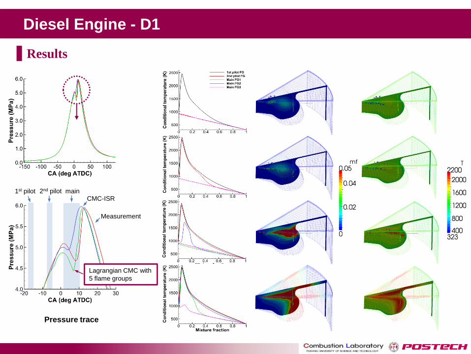
Diesel Engine - D1
Measurement
CMC-ISR 1st pilot 2nd pilot main
Lagrangian CMC with
5 flame groups
-5° ATDC
0° ATDC
6° ATDC
11° ATDC
Pressure trace
Results
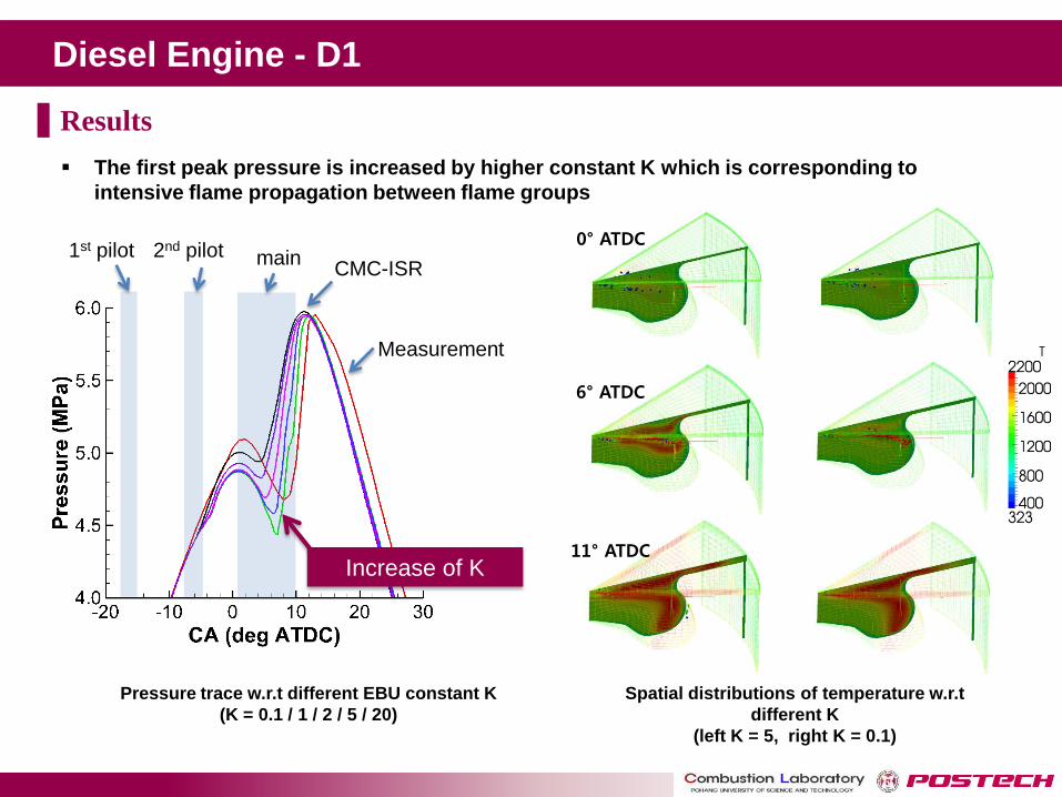
Diesel Engine - D1
Measurement
CMC-ISR 1st pilot 2nd pilot main
Increase of K
0° ATDC
6° ATDC
11° ATDC
The first peak pressure is increased by higher constant K which is corresponding to
intensive flame propagation between flame groups
Pressure trace w.r.t different EBU constant K
(K = 0.1 / 1 / 2 / 5 / 20)
Spatial distributions of temperature w.r.t
different K
(left K = 5, right K = 0.1)
Results

Heavy Oil Furnace - Full Scale
Schematic of the oil boiler
Numerical Method and Models
Grid generation
Grids for computation
Fuel (Heavy fuel oil) is injected from 12 burners into a furnace
Computational domain covers from downstream of burner swirlers to the boiler outlet
Incoming flow at each burner inlet has the swirl number
• Pressure-velocity coupling based on SIMPLE algorithm
• Gauss upwind scheme for spatial discretization of convection term
• k-ε model is employed with the wall function method
• Fuel burning rate is given by the EDM (Eddy-dissipation Model )
• Hexahedral structured mesh with about 4 million elements for RANS simulation
Case description
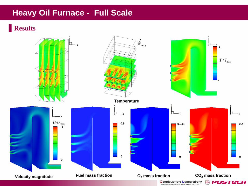
Heavy Oil Furnace - Full Scale
max/T T
0.9
0
Fuel mass fraction
Temperature
1
0
0.233
0
O2 mass fraction
0.2
0
CO2 mass fraction
1
0
Velocity magnitude
U/Umax
Results
Solid Combustion Modeling
Solid Combustion Modeling
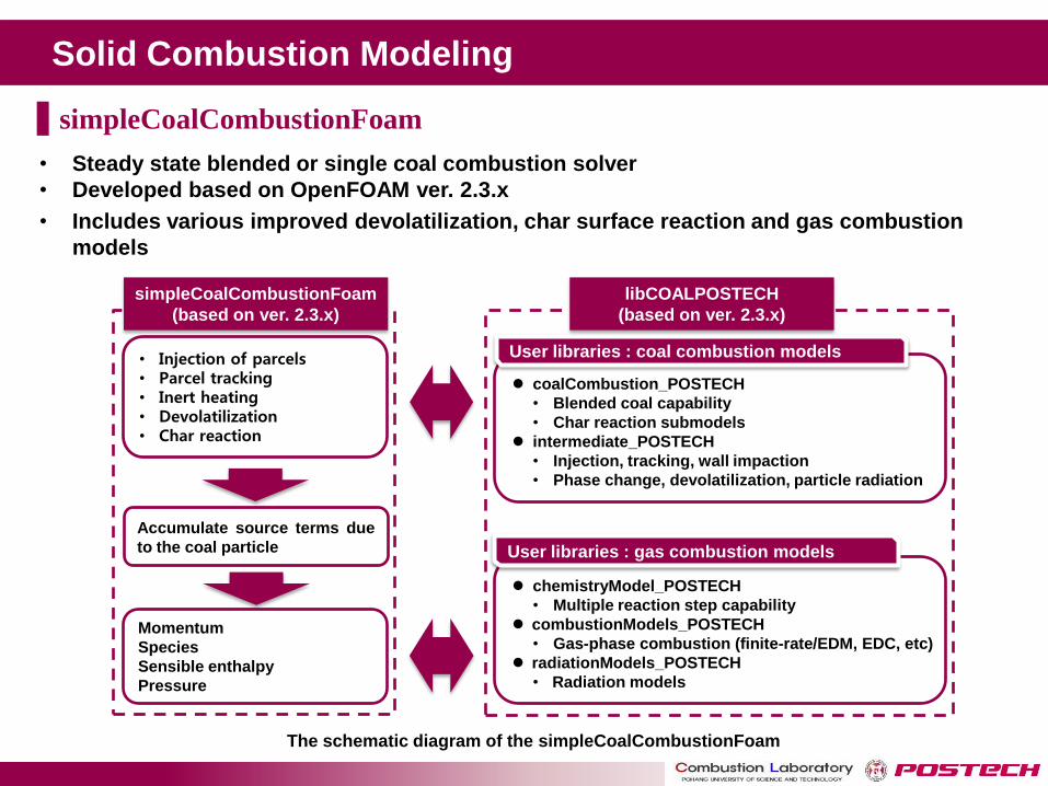
• Injection of parcels • Parcel tracking • Inert heating • Devolatilization • Char reaction
Momentum
Species
Sensible enthalpy
Pressure
coalCombustion_POSTECH
• Blended coal capability
• Char reaction submodels
intermediate_POSTECH
• Injection, tracking, wall impaction
• Phase change, devolatilization, particle radiation
User libraries : coal combustion models
chemistryModel_POSTECH
• Multiple reaction step capability
combustionModels_POSTECH
• Gas-phase combustion (finite-rate/EDM, EDC, etc)
radiationModels_POSTECH
• Radiation models
User libraries : gas combustion models
Accumulate source terms due
to the coal particle
libCOALPOSTECH
(based on ver. 2.3.x)
simpleCoalCombustionFoam
(based on ver. 2.3.x)
The schematic diagram of the simpleCoalCombustionFoam
simpleCoalCombustionFoam
• Steady state blended or single coal combustion solver
• Developed based on OpenFOAM ver. 2.3.x
• Includes various improved devolatilization, char surface reaction and gas combustion
models
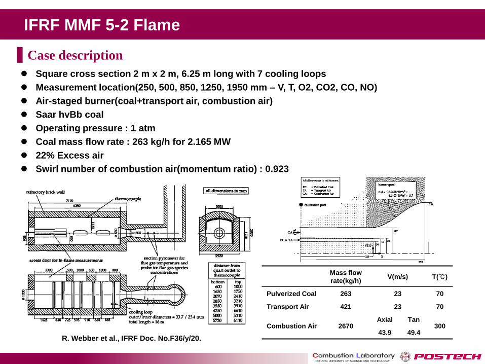
IFRF MMF 5-2 Flame
R. Webber et al., IFRF Doc. No.F36/y/20.
Mass flow
rate(kg/h) V(m/s) T(℃)
Pulverized Coal 263 23 70
Transport Air 421 23 70
Combustion Air 2670 Axial Tan
300 43.9 49.4
Square cross section 2 m x 2 m, 6.25 m long with 7 cooling loops
Measurement location(250, 500, 850, 1250, 1950 mm – V, T, O2, CO2, CO, NO)
Air-staged burner(coal+transport air, combustion air)
Saar hvBb coal
Operating pressure : 1 atm
Coal mass flow rate : 263 kg/h for 2.165 MW
22% Excess air
Swirl number of combustion air(momentum ratio) : 0.923
Case description
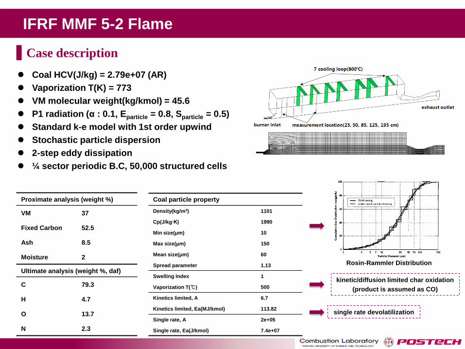
IFRF MMF 5-2 Flame
Proximate analysis (weight %)
VM 37
Fixed Carbon 52.5
Ash 8.5
Moisture 2
Ultimate analysis (weight %, daf)
C 79.3
H 4.7
O 13.7
N 2.3
Coal particle property
Density(kg/m3) 1101
Cp(J/kg∙K) 1990
Min size(μm) 10
Max size(μm) 150
Mean size(μm) 60
Spread parameter 1.13
Swelling Index 1
Vaporization T(℃) 500
Kinetics limited, A 6.7
Kinetics limited, Ea(MJ/kmol) 113.82
Single rate, A 2e+05
Single rate, Ea(J/kmol) 7.4e+07
Rosin-Rammler Distribution
kinetic/diffusion limited char oxidation
(product is assumed as CO)
single rate devolatilization
Coal HCV(J/kg) = 2.79e+07 (AR)
Vaporization T(K) = 773
VM molecular weight(kg/kmol) = 45.6
P1 radiation (α : 0.1, Eparticle = 0.8, Sparticle = 0.5)
Standard k-e model with 1st order upwind
Stochastic particle dispersion
2-step eddy dissipation
¼ sector periodic B.C, 50,000 structured cells
Case description

IFRF MMF 5-2 Flame
Temperature
(K)
Volatile mass frac.
(-)
O2 mass frac.
(-)
CO2 mass frac.
(-)
CO mass frac.
(-)
K
(m2/sec2)
Epsilon
(m2/sec3)
Heat of Reaction
(W)
FLUENT
OpenFOAM
k
epsilon
Single step kinetics devolatilization with 2-step EDM
Kinetic diffusion limited model (also called Field’s model)
Radiation is considered by P1 model
Results
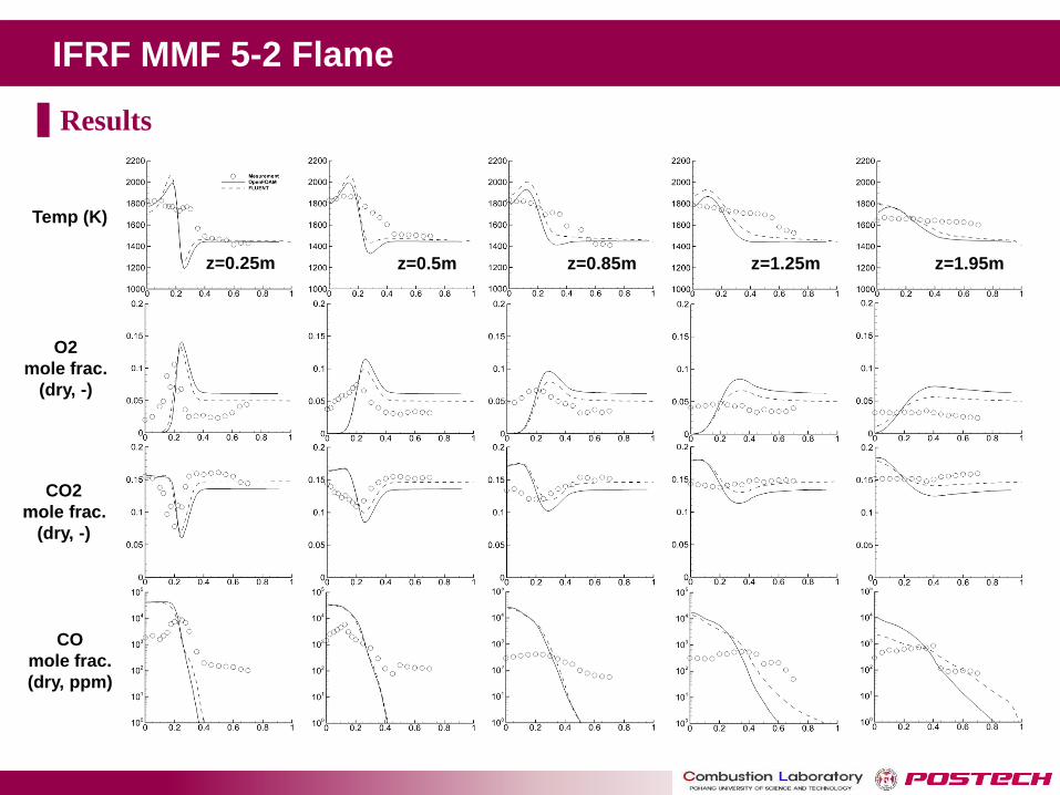
IFRF MMF 5-2 Flame
Temp (K)
O2
mole frac.
(dry, -)
CO2
mole frac.
(dry, -)
CO
mole frac.
(dry, ppm)
z=0.25m z=0.5m z=0.85m z=1.25m z=1.95m
Results
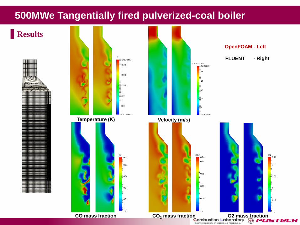
500MWe Tangentially fired pulverized-coal boiler
Results
OpenFOAM - Left
FLUENT - Right
Temperature (K)
CO mass fraction CO2 mass fraction O2 mass fraction
Velocity (m/s)
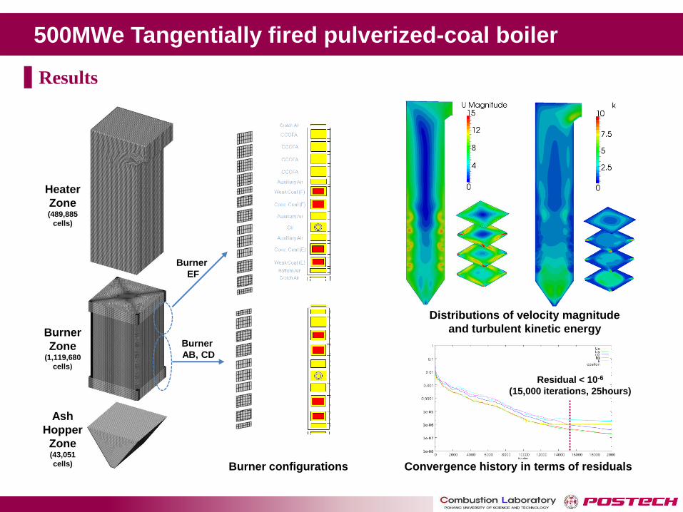
500MWe Tangentially fired pulverized-coal boiler
Distributions of velocity magnitude
and turbulent kinetic energy
Convergence history in terms of residuals
Residual < 10-6
(15,000 iterations, 25hours)
Heater
Zone (489,885
cells)
Burner
Zone (1,119,680
cells)
Ash
Hopper
Zone (43,051
cells) Burner configurations
Burner
AB, CD
Burner
EF
Results
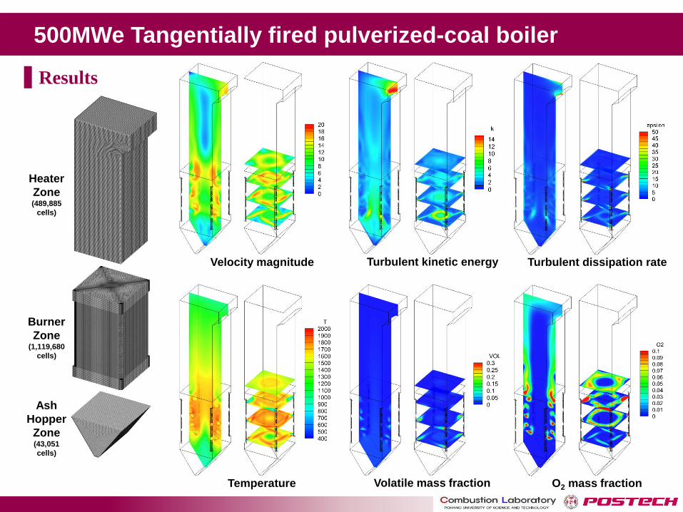
500MWe Tangentially fired pulverized-coal boiler
Heater
Zone (489,885
cells)
Burner
Zone (1,119,680
cells)
Ash
Hopper
Zone (43,051
cells)
Results
Velocity magnitude Turbulent kinetic energy Turbulent dissipation rate
Temperature Volatile mass fraction O2 mass fraction

500MWe Tangentially fired pulverized-coal boiler
Heater
Zone (489,885
cells)
Burner
Zone (1,119,680
cells)
Ash
Hopper
Zone (43,051
cells)
Results
CO mass fraction CO2 mass fraction Heat release rate
Devolatilization rate Char burning rate Particle char
mass frac.
Particle volatile
mass frac.
Material Processing Furnace
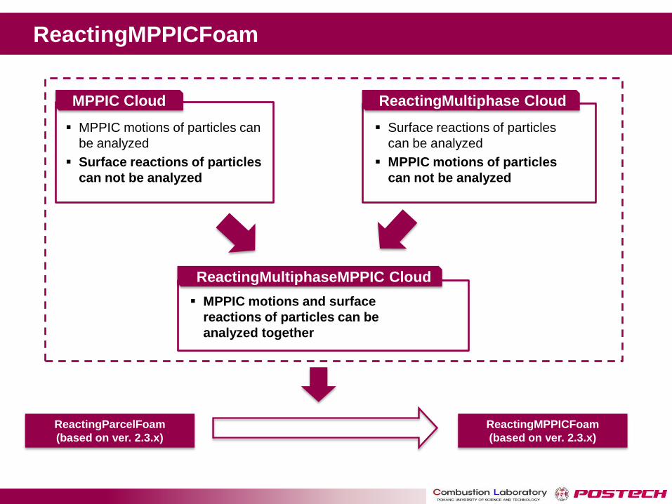
ReactingMPPICFoam
MPPIC Cloud ReactingMultiphase Cloud
MPPIC motions of particles can
be analyzed
Surface reactions of particles
can not be analyzed
Surface reactions of particles
can be analyzed
MPPIC motions of particles
can not be analyzed
ReactingMultiphaseMPPIC Cloud
MPPIC motions and surface
reactions of particles can be
analyzed together
ReactingParcelFoam
(based on ver. 2.3.x)
ReactingMPPICFoam
(based on ver. 2.3.x)
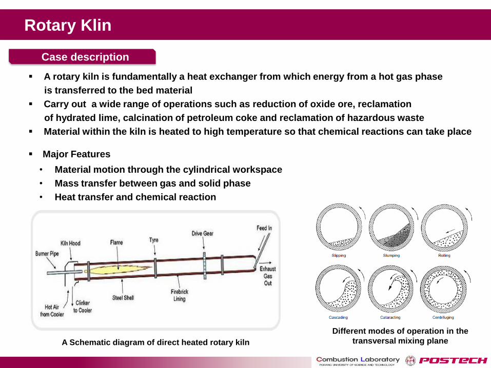
Rotary Klin
A rotary kiln is fundamentally a heat exchanger from which energy from a hot gas phase
is transferred to the bed material
Carry out a wide range of operations such as reduction of oxide ore, reclamation
of hydrated lime, calcination of petroleum coke and reclamation of hazardous waste
Material within the kiln is heated to high temperature so that chemical reactions can take place
Major Features
• Material motion through the cylindrical workspace
• Mass transfer between gas and solid phase
• Heat transfer and chemical reaction
A Schematic diagram of direct heated rotary kiln
Different modes of operation in the
transversal mixing plane
Case description

Rotary Klin
Numerical Method
Geometry & Mesh
• Eulerian(gas phase) - Lagrangian(solid phase) approach
• MP-PIC (Multi Phase – Particle in Cell) method for particle motion
• Arrhenius Chemistry
Test Case
• Fuel : CH4
• Rotational speed: 9.6rpm
• Fuel & Air Injection Velocity : 10m/s
• Type : Iron ore
• Diameter : 6mm
• Initial mass : 1500kg
• Mass input : 30kg/s
• Initial Temperature : 1000K
Particle characteristics
Particle outlet
Air inlet
Fuel inlet
Operating conditions
Particle inlet
Air outlet
1200
1000
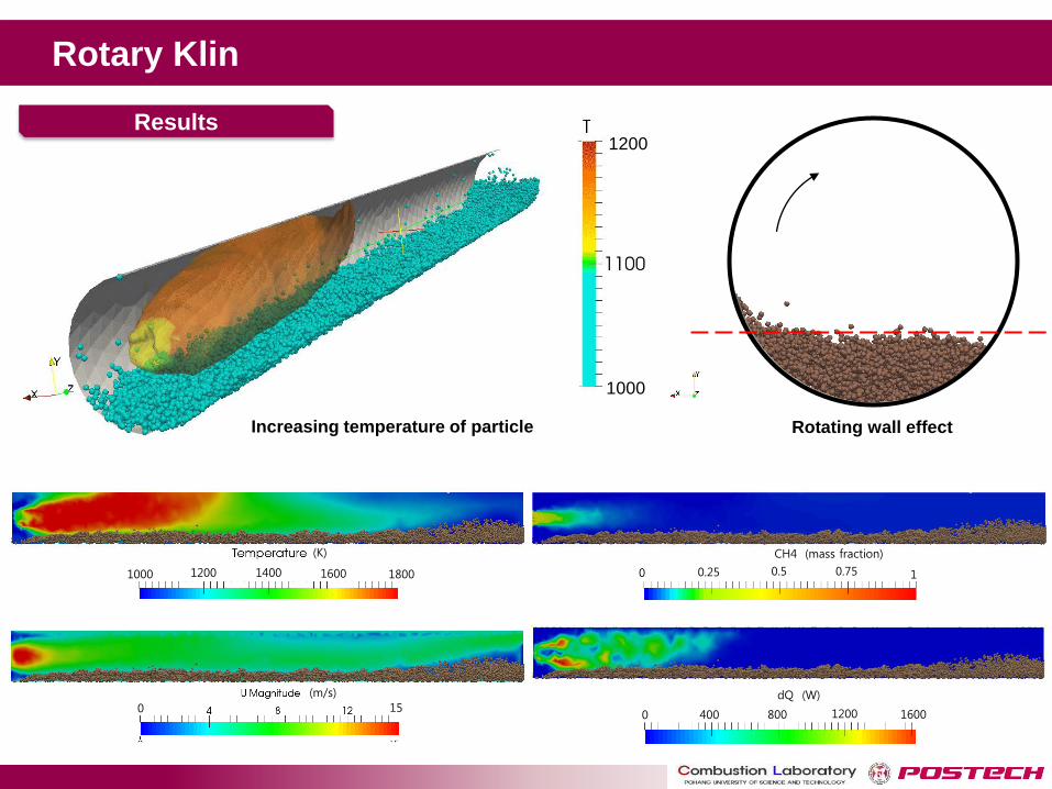
Rotary Klin
Results
Increasing temperature of particle Rotating wall effect
1000 1800 1400 1200 1600
0 15
CH4 (mass fraction) 0 1 0.25 0.75 0.5
0 800 400 1200 1600
(m/s)
(K)
dQ (W)
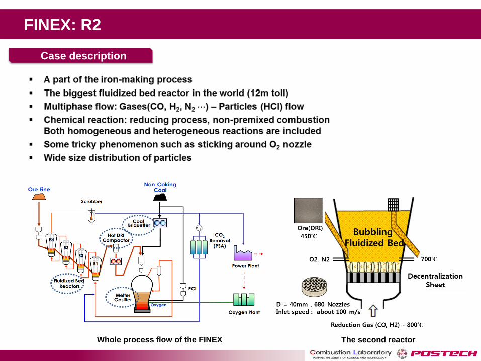
Whole process flow of the FINEX The second reactor
Case description
FINEX: R2
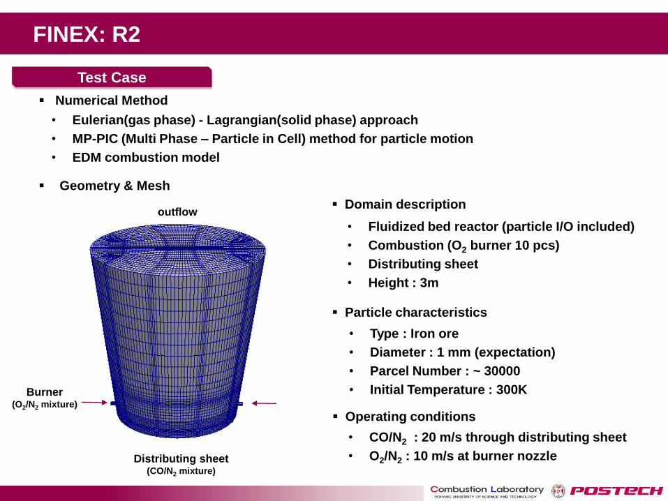
FINEX: R2
Numerical Method
Geometry & Mesh
• Eulerian(gas phase) - Lagrangian(solid phase) approach
• MP-PIC (Multi Phase – Particle in Cell) method for particle motion
• EDM combustion model
Test Case
• CO/N2 : 20 m/s through distributing sheet
• O2/N2 : 10 m/s at burner nozzle
• Type : Iron ore
• Diameter : 1 mm (expectation)
• Parcel Number : ~ 30000
• Initial Temperature : 300K
Particle characteristics
Operating conditions
• Fluidized bed reactor (particle I/O included)
• Combustion (O2 burner 10 pcs)
• Distributing sheet
• Height : 3m
Domain description
Distributing sheet (CO/N2 mixture)
outflow
Burner (O2/N2 mixture)
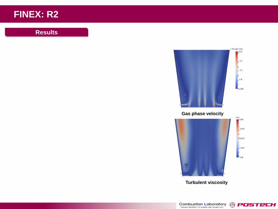
FINEX: R2
Results
Gas phase velocity
Turbulent viscosity

FINEX: R2
Results
CO mass fraction
O2 mass fraction
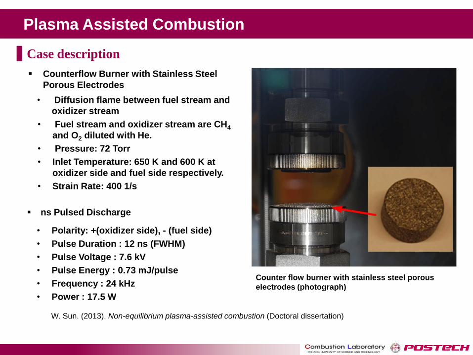
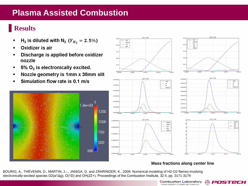
Plasma Assisted Combustion
Counterflow Burner with Stainless Steel
Porous Electrodes
• Diffusion flame between fuel stream and
oxidizer stream
• Fuel stream and oxidizer stream are CH4
and O2 diluted with He.
• Pressure: 72 Torr
• Inlet Temperature: 650 K and 600 K at
oxidizer side and fuel side respectively.
• Strain Rate: 400 1/s
ns Pulsed Discharge
Counter flow burner with stainless steel porous
electrodes (photograph)
W. Sun. (2013). Non-equilibrium plasma-assisted combustion (Doctoral dissertation)
• Polarity: +(oxidizer side), - (fuel side)
• Pulse Duration : 12 ns (FWHM)
• Pulse Voltage : 7.6 kV
• Pulse Energy : 0.73 mJ/pulse
• Frequency : 24 kHz
• Power : 17.5 W
Case description
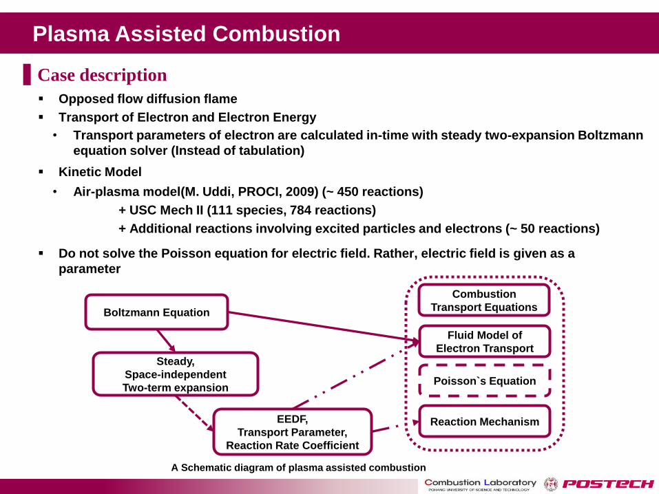
Plasma Assisted Combustion
Opposed flow diffusion flame
Transport of Electron and Electron Energy
Kinetic Model
Do not solve the Poisson equation for electric field. Rather, electric field is given as a
parameter
• Transport parameters of electron are calculated in-time with steady two-expansion Boltzmann
equation solver (Instead of tabulation)
Boltzmann Equation
EEDF,
Transport Parameter,
Reaction Rate Coefficient
Steady,
Space-independent
Two-term expansion
Fluid Model of
Electron Transport
Poisson`s Equation
Combustion
Transport Equations
Reaction Mechanism
A Schematic diagram of plasma assisted combustion
• Air-plasma model(M. Uddi, PROCI, 2009) (~ 450 reactions)
+ USC Mech II (111 species, 784 reactions)
+ Additional reactions involving excited particles and electrons (~ 50 reactions)
Case description
Plasma Assisted Combustion
BOURIG, A., THÉ VENIN, D., MARTIN, J.-., JANIGA, G. and ZÄ HRINGER, K., 2009. Numerical modeling of H2-O2 flames involving
electronically-excited species O2(a1Δg), O(1D) and OH(2Σ+). Proceedings of the Combustion Institute, 32 II, pp. 3171-3179
Mass fractions along center line
Results
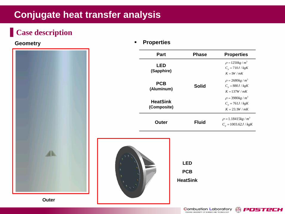
Conjugate heat transfer analysis
Case description
Properties
LED
PCB
HeatSink
Part Phase Properties
LED (Sapphire)
Solid PCB
(Aluminum)
HeatSink (Composite)
Outer Fluid
Geometry
Outer
31250 /
710 /
1 /
p
kg m
C J kgK
K W mK
32680 /
880 /
137 /
p
kg m
C J kgK
K W mK
33980 /
761 /
23.1 /
p
kg m
C J kgK
K W mK
31.18415 /
1003.62 /p
kg m
C J kgK
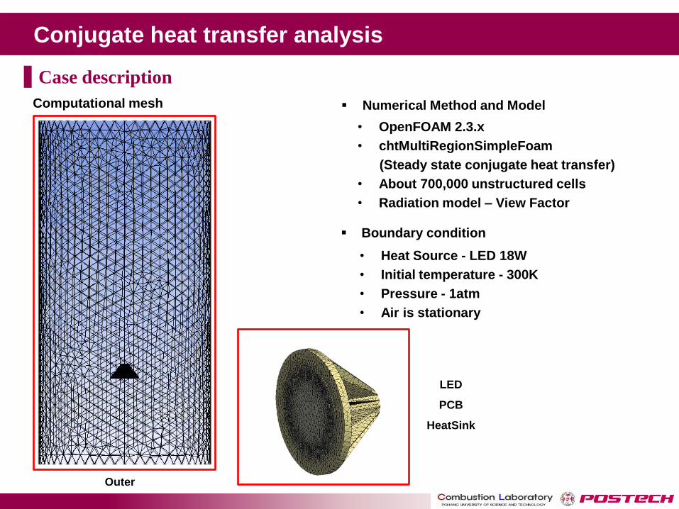
Conjugate heat transfer analysis
Case description
Numerical Method and Model
• OpenFOAM 2.3.x
• chtMultiRegionSimpleFoam
(Steady state conjugate heat transfer)
• About 700,000 unstructured cells
• Radiation model – View Factor
LED
PCB
HeatSink
Boundary condition
• Heat Source - LED 18W
• Initial temperature - 300K
• Pressure - 1atm
• Air is stationary
Computational mesh
Outer
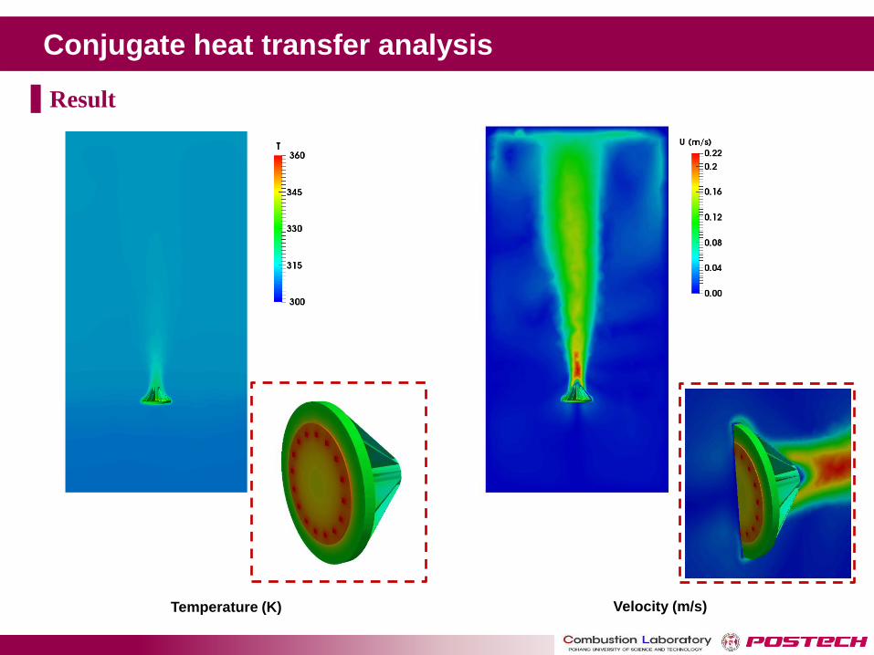
Conjugate heat transfer analysis
Result
Temperature (K) Velocity (m/s)
Conclusion
(1) OpenFOAM is an open source program package useful for simulation of
various industrial combustion devices involving complicated multiphase physics.
(2) Turbulent combustion models are reviewed in the perspective of practical
CFD application for gaseous fuel (Premixed / Non-premixed), liquid fuel (Spray)
and solid fuel (Fixed, Fludized and Entrained Bed).
(3) CFD simulation is now established as a useful design and analysis tool for
complicated industrial combustion devices. Extensive industrial interests shown.
(4) Further work is required for validation and implementation of more advanced
and reliable turbulent combustion models to improve accuracy of the simulation
results.