overview of the energy storage possibilities to support ... · pdf fileoverview of the energy...
TRANSCRIPT
cgvdfagaf
May,
Overview of the Energy Storage
Possibilities to Support the Electrical
Power System
Research Paper to assist the ERRA
Licensing and Competition Committee
Prepared by:
István Táczi
Intern, ERRA
Advisor:
dr. Gábor Szörényi
General Secretary, ERRA
July, 2016

Energy Regulators Regional Association Secretariat R70 Office Complex
Rákóczi út 70-72
1074 Budapest, Hungary
Overview of the Energy Storage Possibilities to Support the Electrical
Power System
István Táczi
Intern
Research Paper
ADVISOR:
Dr. Gábor Szörényi
Budapest, Hungary
2016

Focus of this Research Paper
Energy Regulators Regional Association
R70 Office Complex, Rákóczi út 70-72, 1074 Budapest, Hungary
Tel.: +36 1 477 0456 ǀ Fax: +36 1 477 0455
E-mail: [email protected]ǀ Web: www.erranet.org
2016
Overview of the Energy Storage Possibilities to Support the Electrical Power System
Electrical power grids/systems will basically change in the near future (or in some places, this transformation has already begun): the increasing penetration of renewable energy sources causing high percentage of intermittent and decentralized generation. This procedure will lead to problems which are unknown for a conventionally planned and operated grid. Bidirectional power flows, unbalances, power quality issues and voltage sags (dips) can occur. Energy Storage Systems are able to play a key role in the solutions. The scope of this research paper to provide an up-to-date and detailed summarization about:
the technical background of the different technology possibilities, identify the main parameters of a storage system (for classification and comparison);
the electric power grid/system supporting applications;
regulatory aspects of the deployment. The information gathered from the accessible literature (listed in the reference with download links) gave Regulators a chance to understand the main concepts of these solutions and keep the pace with a rapidly growing part of the energy industry. If Regulators know when and how to utilize these possibilities correctly (introducing support mechanisms), these problems with the power grid could be avoided. The Energy Regulators Regional Association assumes no responsibility for the use that may be made of the information contained in this publication or any errors that may remain in the texts, despite the care taken in preparing them. All views, positions, and conclusions expressed in this publication are those of the author and do not necessarily reflect the views of ERRA and its
members.

Table of Contents
Energy Storage: Holy Grail for Grid Support? ......................................................................................... 1
Motivations in the background .......................................................................................................... 1
Definitions and parameters ................................................................................................................ 2
Changes in the electrical power grid/system ..................................................................................... 2
Facilitating the spreading, projections for the future ......................................................................... 6
Energy Storage Technologies ................................................................................................................. 7
Classification ...................................................................................................................................... 7
Pumped Hydro Storage (PHS) ............................................................................................................. 9
Compressed Air Energy Storage (CAES) ............................................................................................ 10
Battery Technologies ........................................................................................................................ 11
Sodium-sulfur Battery (NaS) ......................................................................................................... 12
Lead-acid batteries ....................................................................................................................... 13
Li-ion batteries ............................................................................................................................. 14
Other battery technologies .......................................................................................................... 15
Flywheel ....................................................................................................................................... 15
Supercapacitors (DLC) .................................................................................................................. 16
Superconducting magnetic energy storage .................................................................................. 17
Thermal Storage ........................................................................................................................... 17
Comparison of technologies ............................................................................................................. 17
Energy Storage Applications ................................................................................................................. 19
Generation and system level applications ........................................................................................ 19
Power plant operational cost savings ........................................................................................... 19
Reducing the size of the transmission system .............................................................................. 20
Reduce imbalance energy charges ............................................................................................... 20
Renewable energy seasonal output shifting ................................................................................. 20
Energy arbitrage ........................................................................................................................... 20
Black start ..................................................................................................................................... 20
Spinning and replacement reserves ............................................................................................. 21
Frequency regulation ................................................................................................................... 22
Local capacity, system capacity .................................................................................................... 23
Renewable energy integration ..................................................................................................... 24
Transmission and distribution system supporting applications ........................................................ 24

Voltage and reactive power support ............................................................................................ 24
Transmission investment deferral ................................................................................................ 25
Transmission congestion relief ..................................................................................................... 26
Distribution upgrade deferral and voltage support ...................................................................... 27
Other possibilities ......................................................................................................................... 27
End-user applications ....................................................................................................................... 28
Power quality, reliability ............................................................................................................... 28
Retail energy time-shift (Time of Use tariff) ................................................................................. 29
Demand side energy management............................................................................................... 29
Summarization and connection with the technologies .................................................................... 30
Energy Storage as a Grid Component: Status, Regulatory Issues and Framework ............................... 32
Current situation .............................................................................................................................. 32
Regulatory framework...................................................................................................................... 33
Market design .................................................................................................................................. 33
Grid fees ........................................................................................................................................... 34
Balancing market .............................................................................................................................. 34
Recommendations for the future ..................................................................................................... 35
Conclusions .......................................................................................................................................... 36
Appendix: Reference Installations of NGK ............................................................................................ 37
References ........................................................................................................................................... 38
List of Abbreviations
T&D - Transmission and distribution networks
ESS - Energy Storage Systems
PHS – Pumped Hydro Storage
CAES – Compressed Air Energy Storage
EPRI – Electric Power Research Institute
BESS – Battery Energy Storage System
DLC – Double Layer Capacitor
SMES – Superconducting Magnetic Energy Storage
TOU – Time of Use
TSO – Transmission System Operator
DSO – Distribution System Operator
VG - Variable Generation
LCOE - Levelized Cost of Electricity
LCOS - Levelized Cost of Storage
Energy Regulators Regional Association Energy Storage: Holy Grail for Grid Support?
1
Energy Storage: Holy Grail for Grid Support?
Motivations in the background
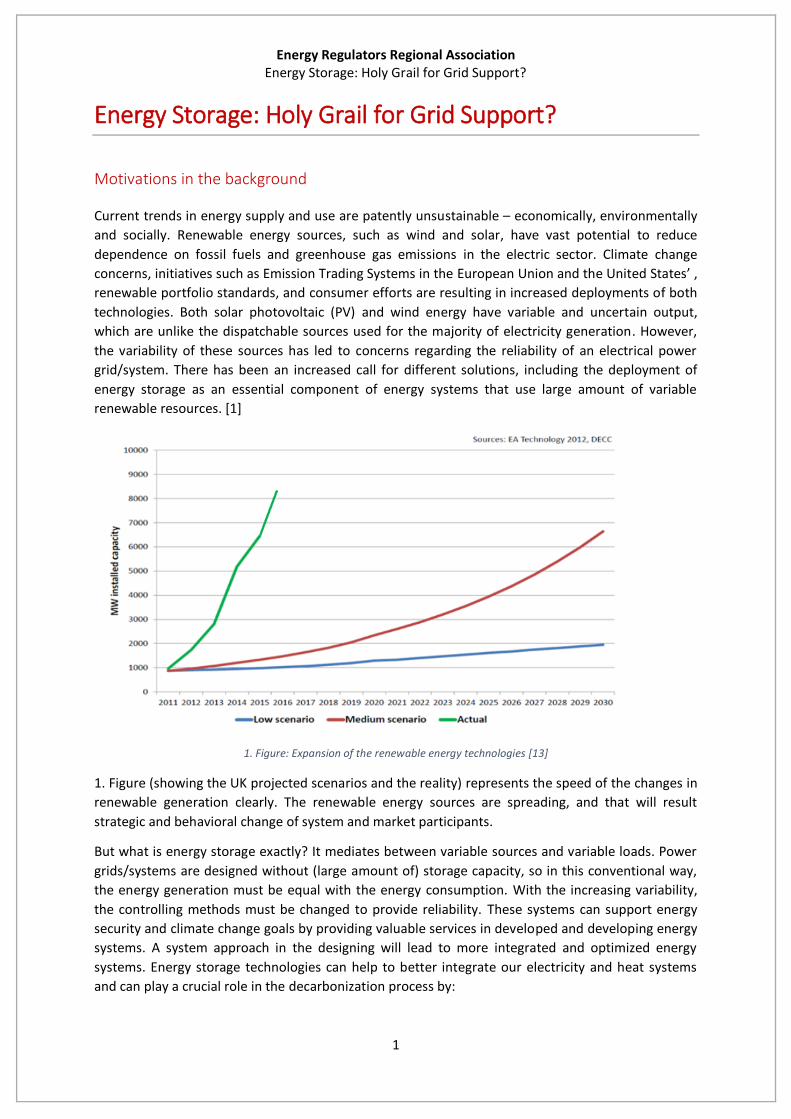
Current trends in energy supply and use are patently unsustainable – economically, environmentally
and socially. Renewable energy sources, such as wind and solar, have vast potential to reduce
dependence on fossil fuels and greenhouse gas emissions in the electric sector. Climate change
concerns, initiatives such as Emission Trading Systems in the European Union and the United States’ ,
renewable portfolio standards, and consumer efforts are resulting in increased deployments of both
technologies. Both solar photovoltaic (PV) and wind energy have variable and uncertain output,
which are unlike the dispatchable sources used for the majority of electricity generation. However,
the variability of these sources has led to concerns regarding the reliability of an electrical power
grid/system. There has been an increased call for different solutions, including the deployment of
energy storage as an essential component of energy systems that use large amount of variable
renewable resources. [1]
1. Figure: Expansion of the renewable energy technologies [13]
1. Figure (showing the UK projected scenarios and the reality) represents the speed of the changes in
renewable generation clearly. The renewable energy sources are spreading, and that will result
strategic and behavioral change of system and market participants.
But what is energy storage exactly? It mediates between variable sources and variable loads. Power
grids/systems are designed without (large amount of) storage capacity, so in this conventional way,
the energy generation must be equal with the energy consumption. With the increasing variability,
the controlling methods must be changed to provide reliability. These systems can support energy
security and climate change goals by providing valuable services in developed and developing energy
systems. A system approach in the designing will lead to more integrated and optimized energy
systems. Energy storage technologies can help to better integrate our electricity and heat systems
and can play a crucial role in the decarbonization process by:

Energy Regulators Regional Association Energy Storage: Holy Grail for Grid Support?
2
improving the efficiency of using the resources
helping to integrate high penetration of renewable energy sources
supporting greater production of energy where it is consumed (decentralization)
increasing energy access
helping to defer capital intensive transmission and distribution system developments
improving electricity grid stability, flexibility, reliability and resilience
The smart grid related network developments cause more complex measuring and controlling
methods which will need flexible, decentralized energy storage to provide the benefits listed above.
Furthermore the growing market of the electric vehicles could play a key role in storage technologies:
the battery manufacturing industry is growing and the charging of those vehicles could be used as a
storage capacity of the electricity systems.
Beside the electrical energy storage there are other options: hydro pumped storage, petroleum
reserves, natural gas storage reservoirs and pipelines and thermal energy (ice, melted salt). [2] [3] [4]
Definitions and parameters
Energy storage technologies absorb energy, store it for a period of time before releasing it to supply
energy or power services. Electrical energy storage systems convert electricity into other forms of
energy (e.g. potential, thermal, chemical or magnetic) and then reverse this process to release
electricity. Just as transmission and distribution (T&D) networks can move electricity over distances
to the end users, energy storage systems can move electricity through time, providing it when and
where it is needed. By setting aside the power system it can decouple supply from demand, and also
increasing the system flexibility and reliability, as well as the utilization. [12] [4] [6]
A widely-used approach for classifying energy storage technologies is the determination according to
the form of energy used. Different applications with different requirements demand different
features from the storage systems. The comprehensive comparison and assessment of all storage
technologies is rather ambitious, but it is necessary to create “storage characteristic” for any further
examination:
Energy storage system parameters could be the following:
Nominal Power: [P]=W;
Capacity: [E]=Wh (J);
Lifetime: [T]= years;
Efficiency: [η]=%;
Discharge time: [Td]=hours;
Response time:: [Tr]=seconds;
Cycle lifetime: [c]=number;
Physical Size: [ρ] [m3] (Could be measured as energy density, power density or actual size)
Changes in the electrical power grid/system
The operation of electric power systems involves a complex process of forecasting the demand for
electricity, and scheduling and operating a large number of power plants to meet that varying
demand. The instantaneous supply of electricity must always meet the constantly changing demand.

Energy Regulators Regional Association Energy Storage: Holy Grail for Grid Support?
3
2. Figure: Hourly loads [Electric Reliability Council of Texas] [1]
2. Figure shows the electricity demand patterns for three weeks during 2005 in Texas. The seasonal
and daily patterns are driven by factors such as the need for heating, cooling, lighting, etc. While this
demand pattern is area specific (Texas), many of the general trends shown in these are common
throughout the United States, and also some other countries, where the air-conditioning is widely
used in the summer period. To meet this demand, utilities build and operate a variety of power plant
types. Base load plants are used to meet the large permanent demand for electricity. These are often
nuclear and coal-fired plants, and operators try to run these plants at full output as much as possible.
While these plants can vary output, their high capital costs, and low variable costs (largely the fuel),
encourage continuous operation. Furthermore, technical constraints restrict rapid change in output
needed to follow load. Variation in load is typically met with load-following or “cycling” plants. These
units are typically hydroelectric generators or plants fueled with natural gas or oil. These are “load-
following” units, which are used to meet most of the day-to-day variable demand; and peaking units,
which meet the peak demand and often run less than a few hundred hours per year. [1]

Energy Regulators Regional Association Energy Storage: Holy Grail for Grid Support?
4
3. Figure: System load following and regulation [1]
In addition to meeting the predictable daily, weekly, and seasonal variation in demand, system
operators must keep additional plants available to meet unforeseen increases in demand, losses of
conventional plants and transmission lines, and other contingencies. This class of responsive reserves
is often referred to as operating reserves and includes meeting frequency regulation (the ability to
respond to small, random fluctuations around normal load), load-forecasting errors (the ability to
respond to a greater or less than predicted change in demand), and contingencies (the ability to
respond to a major contingency such as an unscheduled power plant or transmission line outage).
Both frequency regulation and contingency reserves are among a larger class of services often
referred to as ancillary services1, which require units that can rapidly change output. 3. Figure
illustrates the need for rapidly responding frequency regulation (red) in addition to the longer term
ramping requirements (blue). In this utility system, the morning load increases smoothly by about
400 megawatts (MW) in two hours. During this period, however, there are rapid short-term ramps
(green) of +/- 50 (MW) within a few minutes. [1]
It is important to understand that the generation mix changes cause problems that cannot be solved
with the conventional operation. The controlling methods will change to follow the needs. The need
for operating reserves and the large variation in demand restricts the contribution from low-cost
base load units and increases the need for units that can vary output to provide both load-following
and ancillary services, and this could result a market in which energy storage solutions could be
competitive.
1 https://www.swissgrid.ch/dam/swissgrid/experts/ancillary_services/Dokumente/D100412_AS-concept_V1R0_en.pdf
Energy Regulators Regional Association Energy Storage: Holy Grail for Grid Support?
5
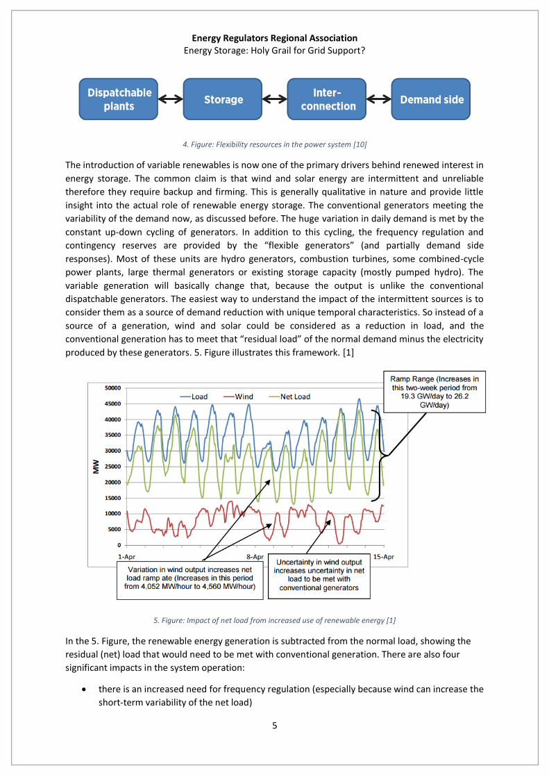
4. Figure: Flexibility resources in the power system [10]
The introduction of variable renewables is now one of the primary drivers behind renewed interest in
energy storage. The common claim is that wind and solar energy are intermittent and unreliable
therefore they require backup and firming. This is generally qualitative in nature and provide little
insight into the actual role of renewable energy storage. The conventional generators meeting the
variability of the demand now, as discussed before. The huge variation in daily demand is met by the
constant up-down cycling of generators. In addition to this cycling, the frequency regulation and
contingency reserves are provided by the “flexible generators” (and partially demand side
responses). Most of these units are hydro generators, combustion turbines, some combined-cycle
power plants, large thermal generators or existing storage capacity (mostly pumped hydro). The
variable generation will basically change that, because the output is unlike the conventional
dispatchable generators. The easiest way to understand the impact of the intermittent sources is to
consider them as a source of demand reduction with unique temporal characteristics. So instead of a
source of a generation, wind and solar could be considered as a reduction in load, and the
conventional generation has to meet that “residual load” of the normal demand minus the electricity
produced by these generators. 5. Figure illustrates this framework. [1]
5. Figure: Impact of net load from increased use of renewable energy [1]
In the 5. Figure, the renewable energy generation is subtracted from the normal load, showing the
residual (net) load that would need to be met with conventional generation. There are also four
significant impacts in the system operation:
there is an increased need for frequency regulation (especially because wind can increase the
short-term variability of the net load)

Energy Regulators Regional Association Energy Storage: Holy Grail for Grid Support?
6
the system needs load-following generators with higher ramp rate (capability of increasing
and decreasing output fast)
there is uncertainty in the wind resource and that affects the net load calculation
the overall ramping range is increasing: the difference between the minimum and maximum
demand and the associated reduction in minimum load, which can force baseload generators
to reduce output (or in extreme cases force the units to cycle off during periods of high wind
output).
Together, the increased variability of the net load requires greater amount of flexibility and operating
reserves in the system. The use of these variable and uncertain resources will require changes in the
operation of the remaining system, and this will incur additional costs, typically referred to as
integration costs. The growing need for flexibility has been brought possible solutions into the
spotlight, including energy storage.
Facilitating the spreading, projections for the future
While some energy storage technologies are mature or near of maturity, most are still in the early
stages of development and currently struggle to compete with other non-storage technologies due
to high costs. They will require additional attention before their potential can be fully realized.
Regulators can help the system operators ensuring greater amount of flexibility and as one solution
accelerate the development and deployment of energy storage technologies by supporting targeted
demonstration projects for promising storage technologies and by eliminating price distortions that
prevent storage technologies from being compensated for the suit of services they provide. [4]
Current accessible survey results indicate that industry participants expect significant capital cost
declines for some energy storage technologies over the next 5-10 years, driven primarily by increased
manufacturing scale and improvement in engineering and design. The most likely drivers are:
reductions in required high cost materials, sub-components and scale
improved manufacturing and design
integration time for manufacturing
technical improvements: control and response time, battery chemistry
improvement in operational sustainability
increasing manufacturing scale and automation [14]

Energy Regulators Regional Association Energy Storage Technologies
7
Energy Storage Technologies
The currently available and emerging energy storage technologies offer wide range of possibilities. It
is important to know the main advantages and disadvantages of each system. The purpose of this
section is to introduce the main particularities of each technology. This paper focuses on the electric
power grid, in hence energy storage means that electrical power can be stored and discharged.
Classification
6. Figure: Classification of energy storage technologies [12]
The maturity of each technology is important: the uncertainties in technical and economical
parameters are less if there is more data from commercial use. The confidence level of the data is
higher in these cases (better estimations). The maturity could be classified to 3 main categories:
commercial: significant experience from several operating units
demonstration and pilot projects: the concept of a system is verified by an integrated unit or
a small pilot facility
research and development: a concept is verified by studies and measurements, initial
hardware development achieved [3]
7. Figure represents the main technologies, even a lot of thermal storage possibilities. It shows the
evaluated maturity stage of the different technologies (in 2014) and the associated risk of the
investment considering the capital costs and the uncertainty of the technology. PHS systems are the
most advanced type from this aspect, but battery technologies are developing fast. [3][4][12]
Energy Regulators Regional Association Energy Storage Technologies
8
7. Figure: Maturity of energy storage technologies [4]
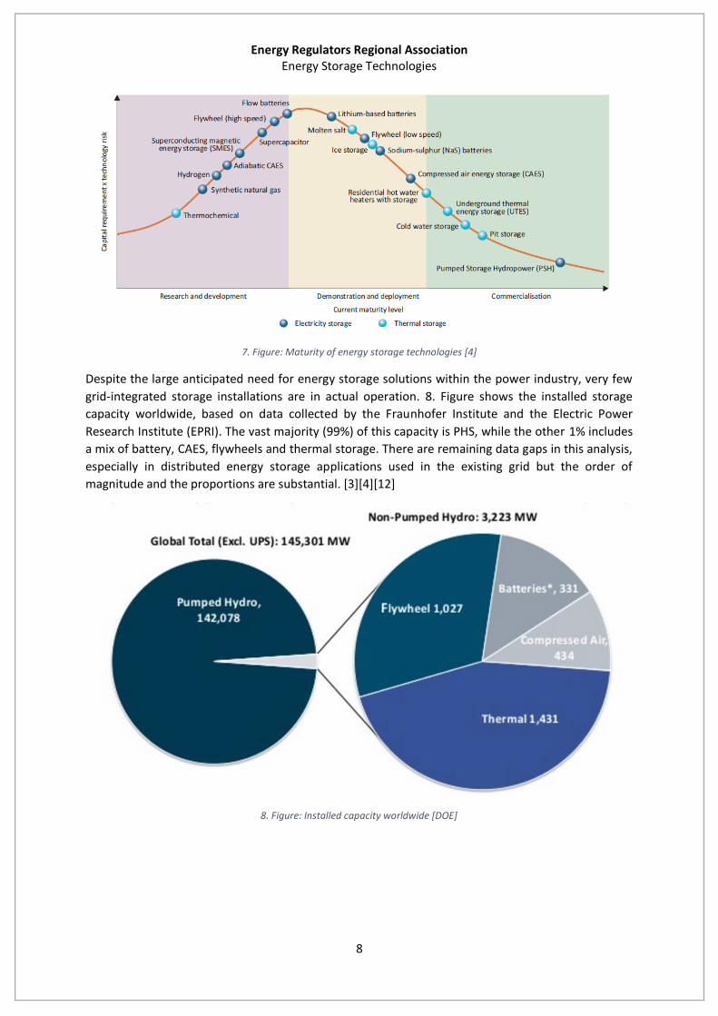
Despite the large anticipated need for energy storage solutions within the power industry, very few
grid-integrated storage installations are in actual operation. 8. Figure shows the installed storage
capacity worldwide, based on data collected by the Fraunhofer Institute and the Electric Power
Research Institute (EPRI). The vast majority (99%) of this capacity is PHS, while the other 1% includes
a mix of battery, CAES, flywheels and thermal storage. There are remaining data gaps in this analysis,
especially in distributed energy storage applications used in the existing grid but the order of
magnitude and the proportions are substantial. [3][4][12]
8. Figure: Installed capacity worldwide [DOE]
Energy Regulators Regional Association Energy Storage Technologies
9
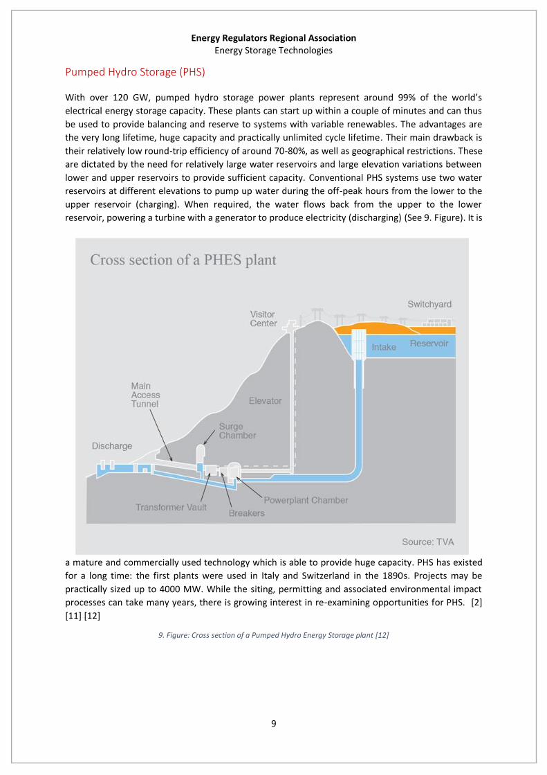
Pumped Hydro Storage (PHS)
With over 120 GW, pumped hydro storage power plants represent around 99% of the world’s
electrical energy storage capacity. These plants can start up within a couple of minutes and can thus
be used to provide balancing and reserve to systems with variable renewables. The advantages are
the very long lifetime, huge capacity and practically unlimited cycle lifetime. Their main drawback is
their relatively low round-trip efficiency of around 70-80%, as well as geographical restrictions. These
are dictated by the need for relatively large water reservoirs and large elevation variations between
lower and upper reservoirs to provide sufficient capacity. Conventional PHS systems use two water
reservoirs at different elevations to pump up water during the off-peak hours from the lower to the
upper reservoir (charging). When required, the water flows back from the upper to the lower
reservoir, powering a turbine with a generator to produce electricity (discharging) (See 9. Figure). It is
a mature and commercially used technology which is able to provide huge capacity. PHS has existed
for a long time: the first plants were used in Italy and Switzerland in the 1890s. Projects may be
practically sized up to 4000 MW. While the siting, permitting and associated environmental impact
processes can take many years, there is growing interest in re-examining opportunities for PHS. [2]
[11] [12]
9. Figure: Cross section of a Pumped Hydro Energy Storage plant [12]

Energy Regulators Regional Association Energy Storage Technologies
10
Compressed Air Energy Storage (CAES)
CAES systems use off-peak electricity to compress air and store it in a reservoir, either an
underground cavern or aboveground pipes or vessels. This air is later heated, expanded and released
to a combustor in a gas turbine to generate electricity during peak periods (See the schematic of this
technology in 10. Figure). This is the only commercial bulk energy storage plant available today, other
than PHS (there are 2 operating systems: one in Germany and one in Alabama, USA). If the heat
released during the compression is dissipated by cooling and not stored, the air must be reheated
prior to expansion in the turbine. This process is called diabatic CAES. The main problem with this
technology is the low efficiency (less than 50%), but the possible use of an adiabatic thermal process
to lose less heat. These plants could operate around 70% efficiency.
Typical underground storage options are caverns, aquifers or abandoned. The advantage of CAES is
its large capacity, the disadvantages are low round-trip efficiency and geographic limitation of
locations. [2][3][4][12]
10. Figure: Schematic of a CAES plant with underground cavern storage

Energy Regulators Regional Association Energy Storage Technologies
11
Battery Technologies
The types of batteries discussed below are secondary (rechargeable) batteries, unlike the non-
rechargeable ones used in some consumer applications. These batteries store energy chemically. The
component materials are sourced from various locations around the world, and their availability or
scarcity has an impact on the cost and sustainability of the battery. These technologies are able to
mitigate both the short (defined as seconds) and long-term (several hours) fluctuations.
In batteries the cathode (the positive part) is separated from the anode (the negative part) by a
porous separator, and ions are allowed to flow between the two charges via an electrolyte. The
chemical reaction creates current and voltage (which together create power) that can be supplied to
a load. In flow batteries, the electrolyte is stored in external tanks and is pumped through a central
reaction unit. This consists of a cathode and anode through which a current is either taken in
(charged) or supplied (discharged) to the external demand/supply source. Since batteries are
composed of chemicals, the manner and conditions under which they are used affects their
performance, cost and life time. There are a lot of important aspects of selecting a battery energy
storage system (BESS) (11. Figure.) [10]
11. Figure: Important considerations for battery selection [10]
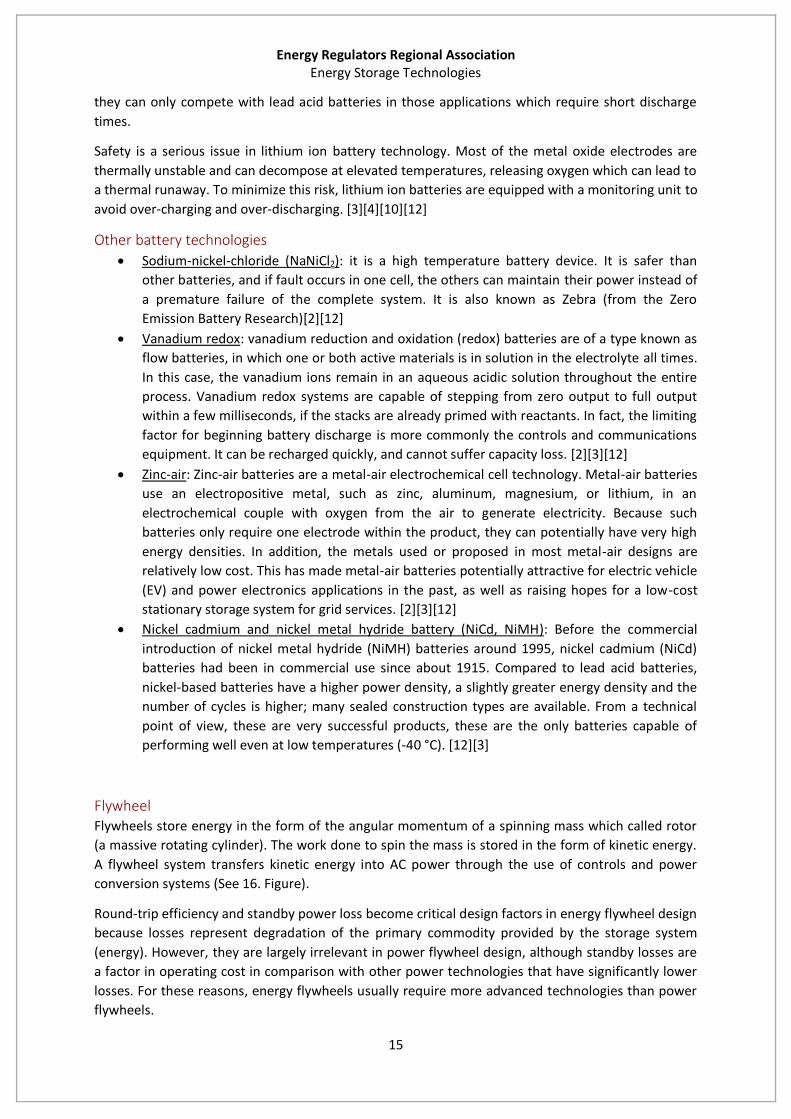
12. Figure shows a schematic of a BESS. The battery alone is not sufficient to connect and operate to
the grid. The alternating current of the systems must be converted (with an inverter) and safety
applications are also needed (circuit breakers, switches). With a controlling and monitoring unit, the
system could be used as an energy storage installation. [2][10][12]
Energy Regulators Regional Association Energy Storage Technologies
12
12. Figure: Schematic of a battery energy storage system [2]
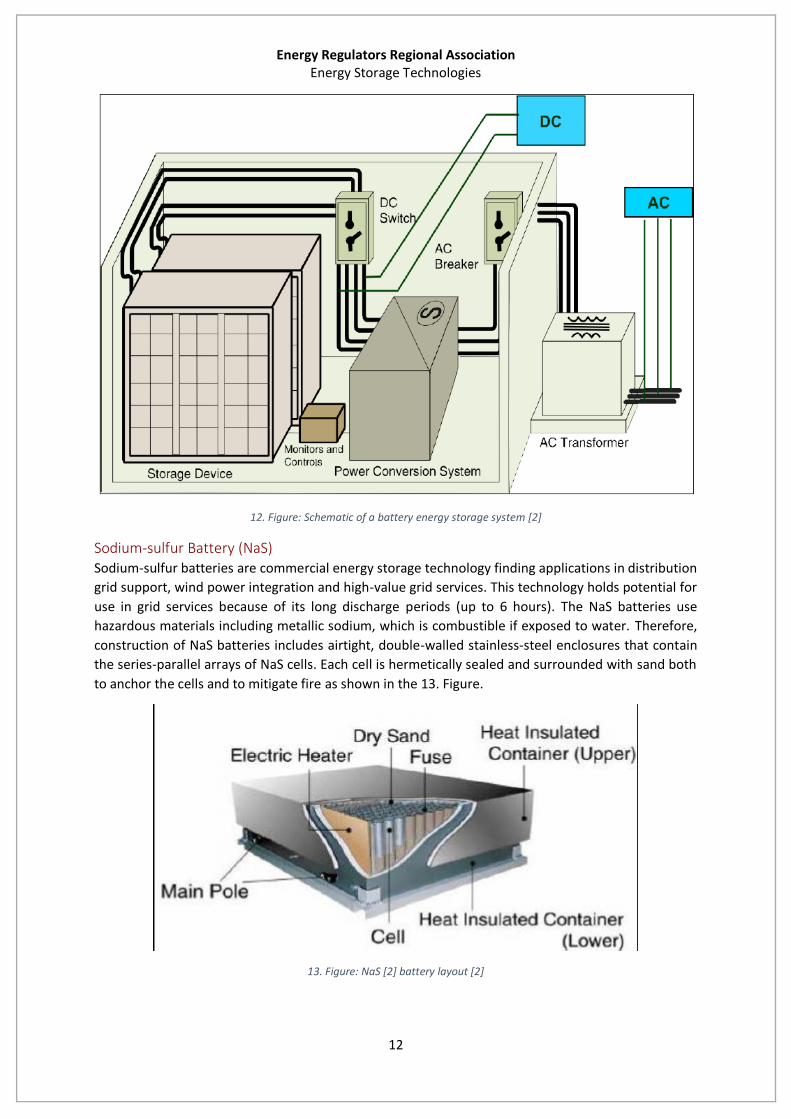
Sodium-sulfur Battery (NaS) Sodium-sulfur batteries are commercial energy storage technology finding applications in distribution
grid support, wind power integration and high-value grid services. This technology holds potential for
use in grid services because of its long discharge periods (up to 6 hours). The NaS batteries use
hazardous materials including metallic sodium, which is combustible if exposed to water. Therefore,
construction of NaS batteries includes airtight, double-walled stainless-steel enclosures that contain
the series-parallel arrays of NaS cells. Each cell is hermetically sealed and surrounded with sand both
to anchor the cells and to mitigate fire as shown in the 13. Figure.
13. Figure: NaS [2] battery layout [2]

Energy Regulators Regional Association Energy Storage Technologies
13
These batteries could response quickly and have been demonstrated at around 200 sites in Japan,
Germany, France, UAE. In the United States there are MW scale applications for reliability
improvements which could switch a microgrid into islanding operation in most of fault cases. There
are also MW scale services for peak shaving, investment deferrals and frequency regulation
according to NGK2. This technology could become the #1 choice for grid-scale battery storage as it is
a market leader right now and has all the technological parameters to remain the best solution. The
main drawback is that to maintain operating temperatures a heat source is required, which uses the
battery’s own stored energy. Due to its physical and chemical parameters, this technology could be
really interesting for stakeholders in the future. [2][3][4][12]
14. Figure: XCELL batteries supporting wind turbines (USA) [2]
Lead-acid batteries Lead-acid batteries are the oldest form of rechargeable battery technology, therefore it is
commercially mature. They are widely used to power engine starters in cars, boats, planes etc. The
positive electrode is composed of lead-dioxide, while the negative electrode is composed of metallic
lead. The active material in both electrodes is highly porous to maximize surface area. The electrolyte
is sulfuric acid. [2]
Their typical applications are emergency power supply systems, stand-alone systems with
photovoltaic generation, battery systems for mitigation of output fluctuations from wind power and
as starter batteries as mentioned before. [12][3]
Disposal of lead-acid batteries is an important part of the life cycle. The environmental and safety
hazards associated with lead require a number of regulations concerning the handling and disposal of
lead-acid batteries. Lead-acid batteries are among the most recycled products in the world. Old
2 NGK Insulators LTD. NAS Division, Power Business Group, Japan

Energy Regulators Regional Association Energy Storage Technologies
14
batteries are accepted by lead-acid manufacturers for recycling. Batteries are separated into their
component parts. The lead plates and grids are smelted to purify the lead for use in new batteries.
Acid electrolyte is neutralized, scrubbed to remove dissolved lead, and released into the
environment. Other component parts are also recycled.[2]
The main drawback of the technology is the capacity decrease when high power is discharged. The
low energy density is also worth to mention. [12]
Li-ion batteries Li-ion battery technology has emerged as the fastest growing platform for stationary storage
applications. It is also commercially proven and mature for consumer electronic applications and also
being positioned as the leading technology platform for plug-in hybrid electric vehicles (PHEV) and
all-electric vehicles.
There are many different Li-ion chemistries, each with specific power-versus-energy characteristics. A
Li-ion battery cell contains two reactive materials capable of undergoing an electron transfer
chemical reaction. To undergo the reaction, the materials must contact each other electrically, either
directly or through a wire, and must be capable of exchanging charged ions to maintain overall
charge neutrality as electrons are transferred. A battery cell is designed to keep the materials from
directly contacting each other and to connect each material to an electrical terminal isolated from
the other material’s terminal. These terminals are the cell’s external contacts (15. Figure).
15. Figure: Principles of a Li-ion battery [2]
The large manufacturing scale of Li-ion batteries (estimated to be approximately 30 GWh by 2015)
could result in potentially lower-cost battery packs – which could also be used and integrated into
systems for grid-support services that require less than 4 hours of storage. Many stationary systems
have been deployed in early field trials to gain experience in siting, grid integration, and operation.[2]
This technology has a high cell voltage level (3,7 Volts) which means that the number of cells in series
with the associated connections and electronics can be reduced. It has a relatively high energy
density and very high efficiency (95-98%). Since lithium ion batteries are currently still expensive,
Energy Regulators Regional Association Energy Storage Technologies
15
they can only compete with lead acid batteries in those applications which require short discharge
times.
Safety is a serious issue in lithium ion battery technology. Most of the metal oxide electrodes are
thermally unstable and can decompose at elevated temperatures, releasing oxygen which can lead to
a thermal runaway. To minimize this risk, lithium ion batteries are equipped with a monitoring unit to
avoid over-charging and over-discharging. [3][4][10][12]
Other battery technologies
Sodium-nickel-chloride (NaNiCl2): it is a high temperature battery device. It is safer than
other batteries, and if fault occurs in one cell, the others can maintain their power instead of
a premature failure of the complete system. It is also known as Zebra (from the Zero
Emission Battery Research)[2][12]
Vanadium redox: vanadium reduction and oxidation (redox) batteries are of a type known as
flow batteries, in which one or both active materials is in solution in the electrolyte all times.
In this case, the vanadium ions remain in an aqueous acidic solution throughout the entire
process. Vanadium redox systems are capable of stepping from zero output to full output
within a few milliseconds, if the stacks are already primed with reactants. In fact, the limiting
factor for beginning battery discharge is more commonly the controls and communications
equipment. It can be recharged quickly, and cannot suffer capacity loss. [2][3][12]
Zinc-air: Zinc-air batteries are a metal-air electrochemical cell technology. Metal-air batteries
use an electropositive metal, such as zinc, aluminum, magnesium, or lithium, in an
electrochemical couple with oxygen from the air to generate electricity. Because such
batteries only require one electrode within the product, they can potentially have very high
energy densities. In addition, the metals used or proposed in most metal-air designs are
relatively low cost. This has made metal-air batteries potentially attractive for electric vehicle
(EV) and power electronics applications in the past, as well as raising hopes for a low-cost
stationary storage system for grid services. [2][3][12]
Nickel cadmium and nickel metal hydride battery (NiCd, NiMH): Before the commercial
introduction of nickel metal hydride (NiMH) batteries around 1995, nickel cadmium (NiCd)
batteries had been in commercial use since about 1915. Compared to lead acid batteries,
nickel-based batteries have a higher power density, a slightly greater energy density and the
number of cycles is higher; many sealed construction types are available. From a technical
point of view, these are very successful products, these are the only batteries capable of
performing well even at low temperatures (-40 °C). [12][3]
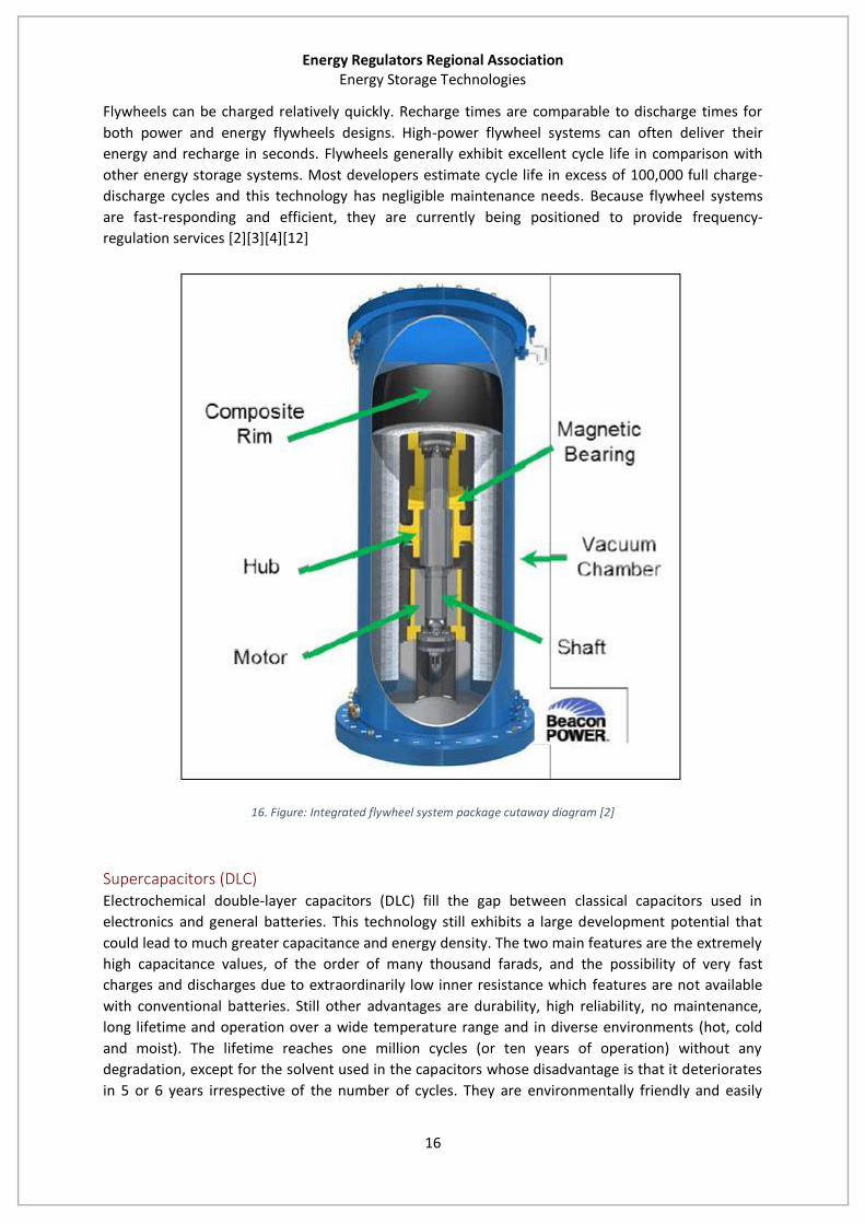
Flywheel Flywheels store energy in the form of the angular momentum of a spinning mass which called rotor
(a massive rotating cylinder). The work done to spin the mass is stored in the form of kinetic energy.
A flywheel system transfers kinetic energy into AC power through the use of controls and power
conversion systems (See 16. Figure).
Round-trip efficiency and standby power loss become critical design factors in energy flywheel design
because losses represent degradation of the primary commodity provided by the storage system
(energy). However, they are largely irrelevant in power flywheel design, although standby losses are
a factor in operating cost in comparison with other power technologies that have significantly lower
losses. For these reasons, energy flywheels usually require more advanced technologies than power
flywheels.
Energy Regulators Regional Association Energy Storage Technologies
16
Flywheels can be charged relatively quickly. Recharge times are comparable to discharge times for
both power and energy flywheels designs. High-power flywheel systems can often deliver their
energy and recharge in seconds. Flywheels generally exhibit excellent cycle life in comparison with
other energy storage systems. Most developers estimate cycle life in excess of 100,000 full charge-
discharge cycles and this technology has negligible maintenance needs. Because flywheel systems
are fast-responding and efficient, they are currently being positioned to provide frequency-
regulation services [2][3][4][12]
16. Figure: Integrated flywheel system package cutaway diagram [2]
Supercapacitors (DLC) Electrochemical double-layer capacitors (DLC) fill the gap between classical capacitors used in
electronics and general batteries. This technology still exhibits a large development potential that
could lead to much greater capacitance and energy density. The two main features are the extremely
high capacitance values, of the order of many thousand farads, and the possibility of very fast
charges and discharges due to extraordinarily low inner resistance which features are not available
with conventional batteries. Still other advantages are durability, high reliability, no maintenance,
long lifetime and operation over a wide temperature range and in diverse environments (hot, cold
and moist). The lifetime reaches one million cycles (or ten years of operation) without any
degradation, except for the solvent used in the capacitors whose disadvantage is that it deteriorates
in 5 or 6 years irrespective of the number of cycles. They are environmentally friendly and easily
Energy Regulators Regional Association Energy Storage Technologies
17
recycled or neutralized. The efficiency is typically around 90 % and discharge times are in the range
of seconds to hours. [3] [12]
Superconducting magnetic energy storage Superconducting magnetic energy storage (SMES) systems work according to an electrodynamic
principle. The energy is stored in the magnetic field created by the flow of direct current in a
superconducting coil, which is kept below its superconducting critical temperature. The main
component is a coil made of superconducting material. The main advantage of SMES is the very quick
response time: the requested power is available almost instantaneously. Moreover the system is
characterized by its high overall round-trip efficiency and the very high power output which can be
provided for a short period of time. [3][12]
Thermal Storage Thermal energy storage systems store available heat by different means in an insulated repository
for later use. Thermal storage can be subdivided into different technologies: storage of sensible heat,
storage of latent heat, and thermo-chemical and absorption storage. [12]
The storage of sensible heat is one of the best-known and most widespread technologies, with the
domestic hot water tank as an example. The storage medium may be a liquid such as water or
thermo-oil, or a solid such as concrete or the ground. Latent heat storage is accomplished by using
phase change materials (PCMs) as storage media. Sorption (adsorption, absorption) storage systems
work as thermo-chemical heat pumps under vacuum conditions and have a more complex design.
[12]
Combined heat and power Plants (CHP) could detach heat generation from demand such as electrical
energy storage does to electric power grids. Heat storage has more commercial level projects so it is
important to consider it as an opportunity.
Comparison of technologies
The portfolio of energy storage technologies can be considered for providing a range of services to
the power grid and can be positioned around their nominal power and capacity relationship. Figure
17 shows that compressed air energy storage and pumped hydro are capable of discharge times in
tens of hours, with correspondingly high sizes (~1000 MW range). In contrast to the capabilities of
these two technologies, batteries and flywheels are positioned around lower power and shorter
discharge times. However, those comparisons are very general, intended for conceptual use only,
many of the storage options have broader duration and power ranges than shown. Table 1
summarizes all the relevant technical parameters for energy storage systems.

Energy Regulators Regional Association Energy Storage Technologies
18
1. Table: Technical parameters of energy storage systems [12][3][4]
17. Figure: Energy storage system comparison: Discharge time at System power ratings [2]
Technology Response
time Energy density
Wh/Kg Power density
W/I Discharge
time Efficiency Lifetime Cycle lifetime
PHS min 0,2-2 0,1-0,2 hour 70-80 >50 >15000
CAES min - 0,2-0,6 hour 41-75 >25 >10000
Flywheel <sec 42154 5000 sec 80-90 15.0-20 20000-
10000000
Lead-acid battery
<sec 30-45 90-700 min 75-90 3.0-15 250-1500
NiCd battery <sec 15-40 75-700 hour 60-80 5.0-20 1500-3000
NiMH battery <sec 40-80 500-3000 hour 65-75 5.0-10 600-1200
Li-ion battery <sec 60-200 1300-10000 hour 85-98 5.0-15 500-10000
Zinc-air battery <sec 130-200 50-100 hour 50-70 >1 >1000
NaS battery <sec 100-250 120-160 hour 70-85 10.0-15 2500-4500
NaNiCl battery <sec 100-200 250-270 hour 80-90 10.0-15 ~1000
Vanadium-redox battery
<sec 15-50 0,5-2 hour 60-75 5.0-20 >10000
Hydrogen Centralized Decentralized
sec-min 33330
0,2-2 2,0-20
hour-day 34-44 10.0-30 1000-10000
Syngas min 10000 0,2-2 hour-day 30-38 10.0-30 1000-10000
Supercapacitor <sec 1,0-15 40000-120000 sec 85-98 4.0-12 10000-100000
SMES <sec - 2600 sec 75-80 - -
Energy Regulators Regional Association Energy Storage Applications
19
Energy Storage Applications
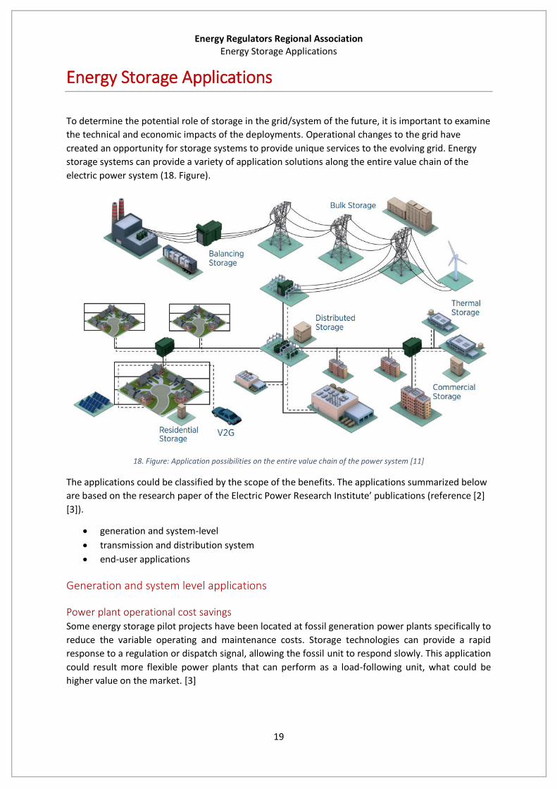
To determine the potential role of storage in the grid/system of the future, it is important to examine
the technical and economic impacts of the deployments. Operational changes to the grid have
created an opportunity for storage systems to provide unique services to the evolving grid. Energy
storage systems can provide a variety of application solutions along the entire value chain of the
electric power system (18. Figure).
18. Figure: Application possibilities on the entire value chain of the power system [11]
The applications could be classified by the scope of the benefits. The applications summarized below
are based on the research paper of the Electric Power Research Institute’ publications (reference [2]
[3]).
generation and system-level
transmission and distribution system
end-user applications
Generation and system level applications
Power plant operational cost savings Some energy storage pilot projects have been located at fossil generation power plants specifically to
reduce the variable operating and maintenance costs. Storage technologies can provide a rapid
response to a regulation or dispatch signal, allowing the fossil unit to respond slowly. This application
could result more flexible power plants that can perform as a load-following unit, what could be
higher value on the market. [3]

Energy Regulators Regional Association Energy Storage Applications
20
Reducing the size of the transmission system Transmission lines are long-lived capital assets that are constructed in fixed size increments. With a
proper use of energy storage, a more decentralized structure could be feasible where generation is
near the consumption.
Reduce imbalance energy charges Imbalance energy charges are assessed by the transmission system operator (or determined by the
balancing markets) when load or generation deviates from its designated level (schedule) beyond a
set range. With proper use of energy storage, industry stakeholders could shift their needs to avoid
those charges. [3]
Renewable energy seasonal output shifting Some energy storage devices such as pumped hydroelectric resources can store energy over long
periods of time. Different parts of the electric grid have different seasonal peaking profiles. In warm
climates, the peak season is during the summer when the air conditioning load is the highest. In cold
climates, the peak season is often in the winter when electrical heating load is high. Large-scale
energy storage could be used to shift the excess renewable energy produced in non-peak seasons to
be available during peak times. [3]
Energy arbitrage Energy prices are highly volatile, but tend to show a daily pattern. Electric energy time shift involves
purchasing inexpensive electric energy which is available during periods when prices or system
marginal costs are low, to charge the storage system so that the stored energy can be used or sold at
a later time when the price or cost are high. Alternatively, storage can provide similar time-shift duty
by storing excess energy production, which would otherwise be curtailed, from renewable sources
such as wind or photovoltaic. [2][3]
The storage parameter ranges for energy arbitrage is highly dependent on the exact purpose, but (as
for every other application) EPRI (in reference [2] and [3]) provided estimation:
Storage system size range: 1-500 MW
Target discharge duration range: <1 hour
Minimum cycles/year: 250+
The scale covers wide range of optimal power from smaller PV systems to larger operator controlled
applications. Both storage variable operating cost (non-energy-related) and storage efficiency are
especially important for this service. [3][2]
Black start Storage systems provide an active reserve of power and energy within the grid and can be used to
energize transmission and distribution lines and provide station power to bring power plants on line
after a catastrophic failure on the grid. Storage can provide a similar startup power to larger power
plants, if the storage system is suitably sited and there is a clear transmission path to the power plant
from the storage system’s location. Many power plants require electricity to perform start-up
operations. Plants with the black start ability could get paid for the service. [2] [3]
Storage system size range: 5-50 MW
Target discharge duration range: 15 minutes- 1 hour
Minimum cycles/year: 10-20
Energy Regulators Regional Association Energy Storage Applications
21
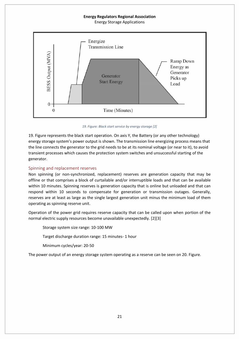
19. Figure: Black start service by energy storage [2[
19. Figure represents the black start operation. On axis Y, the Battery (or any other technology)
energy storage system’s power output is shown. The transmission line energizing process means that
the line connects the generator to the grid needs to be at its nominal voltage (or near to it), to avoid
transient processes which causes the protection system switches and unsuccessful starting of the
generator.
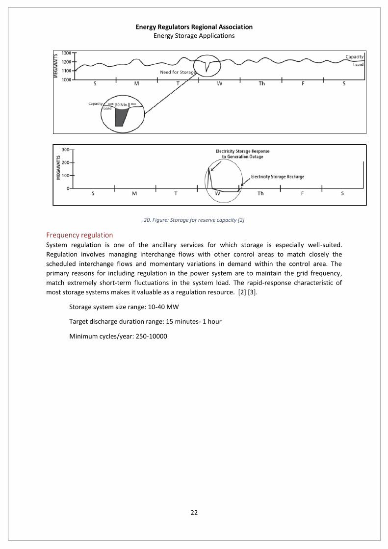
Spinning and replacement reserves Non spinning (or non-synchronized, replacement) reserves are generation capacity that may be
offline or that comprises a block of curtailable and/or interruptible loads and that can be available
within 10 minutes. Spinning reserves is generation capacity that is online but unloaded and that can
respond within 10 seconds to compensate for generation or transmission outages. Generally,
reserves are at least as large as the single largest generation unit minus the minimum load of them
operating as spinning reserve unit.
Operation of the power grid requires reserve capacity that can be called upon when portion of the
normal electric supply resources become unavailable unexpectedly. [2][3]
Storage system size range: 10-100 MW
Target discharge duration range: 15 minutes- 1 hour
Minimum cycles/year: 20-50
The power output of an energy storage system operating as a reserve can be seen on 20. Figure.
Energy Regulators Regional Association Energy Storage Applications
22
20. Figure: Storage for reserve capacity [2]
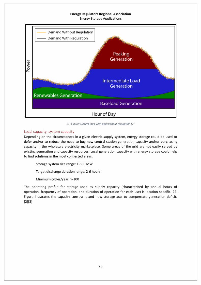
Frequency regulation System regulation is one of the ancillary services for which storage is especially well-suited.
Regulation involves managing interchange flows with other control areas to match closely the
scheduled interchange flows and momentary variations in demand within the control area. The
primary reasons for including regulation in the power system are to maintain the grid frequency,
match extremely short-term fluctuations in the system load. The rapid-response characteristic of
most storage systems makes it valuable as a regulation resource. [2] [3].
Storage system size range: 10-40 MW
Target discharge duration range: 15 minutes- 1 hour
Minimum cycles/year: 250-10000
Energy Regulators Regional Association Energy Storage Applications
23
21. Figure: System load with and without regulation [2]
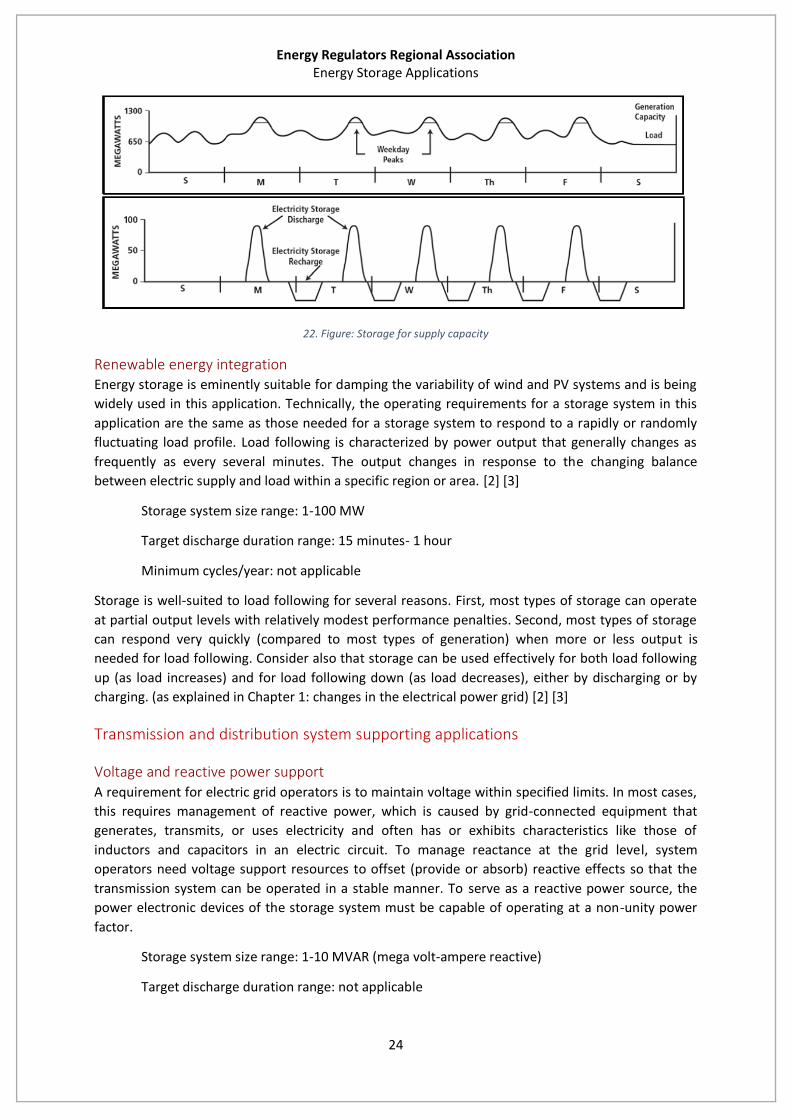
Local capacity, system capacity
Depending on the circumstances in a given electric supply system, energy storage could be used to
defer and/or to reduce the need to buy new central station generation capacity and/or purchasing
capacity in the wholesale electricity marketplace. Some areas of the grid are not easily served by
existing generation and capacity resources. Local generation capacity with energy storage could help
to find solutions in the most congested areas.
Storage system size range: 1-500 MW
Target discharge duration range: 2-6 hours
Minimum cycles/year: 5-100
The operating profile for storage used as supply capacity (characterized by annual hours of
operation, frequency of operation, and duration of operation for each use) is location-specific. 22.
Figure illustrates the capacity constraint and how storage acts to compensate generation deficit.
[2][3]
Energy Regulators Regional Association Energy Storage Applications
24
22. Figure: Storage for supply capacity
Renewable energy integration Energy storage is eminently suitable for damping the variability of wind and PV systems and is being
widely used in this application. Technically, the operating requirements for a storage system in this
application are the same as those needed for a storage system to respond to a rapidly or randomly
fluctuating load profile. Load following is characterized by power output that generally changes as
frequently as every several minutes. The output changes in response to the changing balance
between electric supply and load within a specific region or area. [2] [3]
Storage system size range: 1-100 MW
Target discharge duration range: 15 minutes- 1 hour
Minimum cycles/year: not applicable
Storage is well-suited to load following for several reasons. First, most types of storage can operate
at partial output levels with relatively modest performance penalties. Second, most types of storage
can respond very quickly (compared to most types of generation) when more or less output is
needed for load following. Consider also that storage can be used effectively for both load following
up (as load increases) and for load following down (as load decreases), either by discharging or by
charging. (as explained in Chapter 1: changes in the electrical power grid) [2] [3]
Transmission and distribution system supporting applications
Voltage and reactive power support A requirement for electric grid operators is to maintain voltage within specified limits. In most cases,
this requires management of reactive power, which is caused by grid-connected equipment that
generates, transmits, or uses electricity and often has or exhibits characteristics like those of
inductors and capacitors in an electric circuit. To manage reactance at the grid level, system
operators need voltage support resources to offset (provide or absorb) reactive effects so that the
transmission system can be operated in a stable manner. To serve as a reactive power source, the
power electronic devices of the storage system must be capable of operating at a non-unity power
factor.
Storage system size range: 1-10 MVAR (mega volt-ampere reactive)
Target discharge duration range: not applicable

Energy Regulators Regional Association Energy Storage Applications
25
Minimum cycles/year: not applicable
Normally, designated power plants are used to generate reactive power (VAR) to offset the grid
element’s reactive effects. These power plants could be displaced by strategically placed energy
storage within the grid at central locations or taking the distributed approach and placing multiple
VAR-support storage systems near large loads. 23. Figure shows some possible occasions where
storage provides reactive support to the grid with the change of its power factor to compensate the
reactive power flows on the grid. This solution could help to reduce voltage stability problems as
well. [2][3]
23. Figure: Energy storage for voltage support services [2]
Transmission investment deferral Transmission upgrade investments are necessary when transmission congestion limits the amount of
electricity that can be sent through a pre-existing transmission line during peak hours. Transmission
upgrade deferral involves delaying – in some cases avoiding entirely – transmission and distribution
network investments by using relatively small amounts of storage. By reducing peak load growth,
energy storage could defer the transmission upgrade investments for a few years.
Storage system size range: 10-100 MW
Target discharge duration range: 2-8 hours
Minimum cycles/year: 10-50
The key consideration is that a small amount of storage can be used to provide enough incremental
capacity to defer the need for a large lump investment in transmission equipment. Doing so reduces
overall cost to ratepayers, improves utility asset utilization, allows use of the capital for other
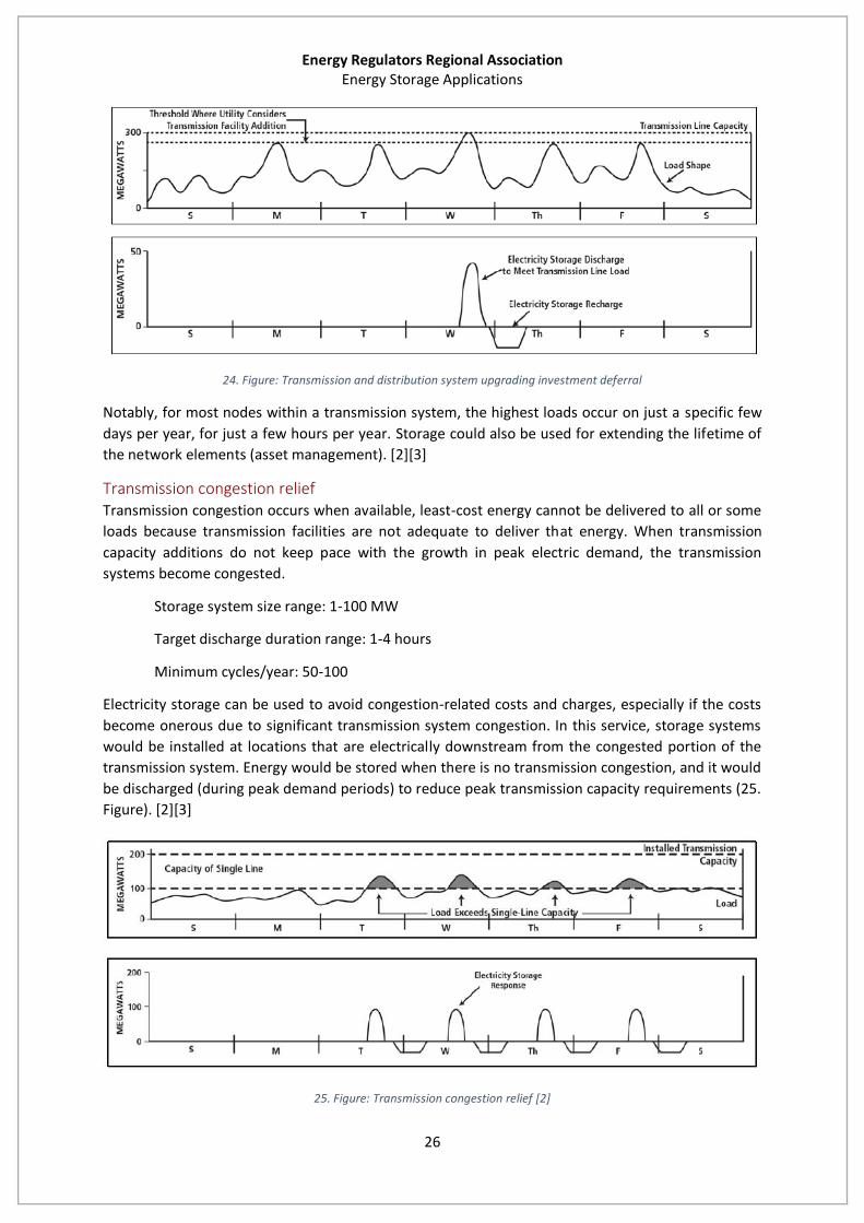
projects, and reduces the financial risk associated with lump investments. 24. Figure shows a possible
way to use storage systems for investment deferral: when the load is over the current transmission
line capacity, storage discharges and provides added capacity. When the load goes under the current
transmission line capacity the storage could be recharged while all the consumers are supplied.
Energy Regulators Regional Association Energy Storage Applications
26
24. Figure: Transmission and distribution system upgrading investment deferral
Notably, for most nodes within a transmission system, the highest loads occur on just a specific few
days per year, for just a few hours per year. Storage could also be used for extending the lifetime of
the network elements (asset management). [2][3]
Transmission congestion relief Transmission congestion occurs when available, least-cost energy cannot be delivered to all or some
loads because transmission facilities are not adequate to deliver that energy. When transmission
capacity additions do not keep pace with the growth in peak electric demand, the transmission
systems become congested.
Storage system size range: 1-100 MW
Target discharge duration range: 1-4 hours
Minimum cycles/year: 50-100
Electricity storage can be used to avoid congestion-related costs and charges, especially if the costs
become onerous due to significant transmission system congestion. In this service, storage systems
would be installed at locations that are electrically downstream from the congested portion of the
transmission system. Energy would be stored when there is no transmission congestion, and it would
be discharged (during peak demand periods) to reduce peak transmission capacity requirements (25.
Figure). [2][3]
25. Figure: Transmission congestion relief [2]
Energy Regulators Regional Association Energy Storage Applications
27
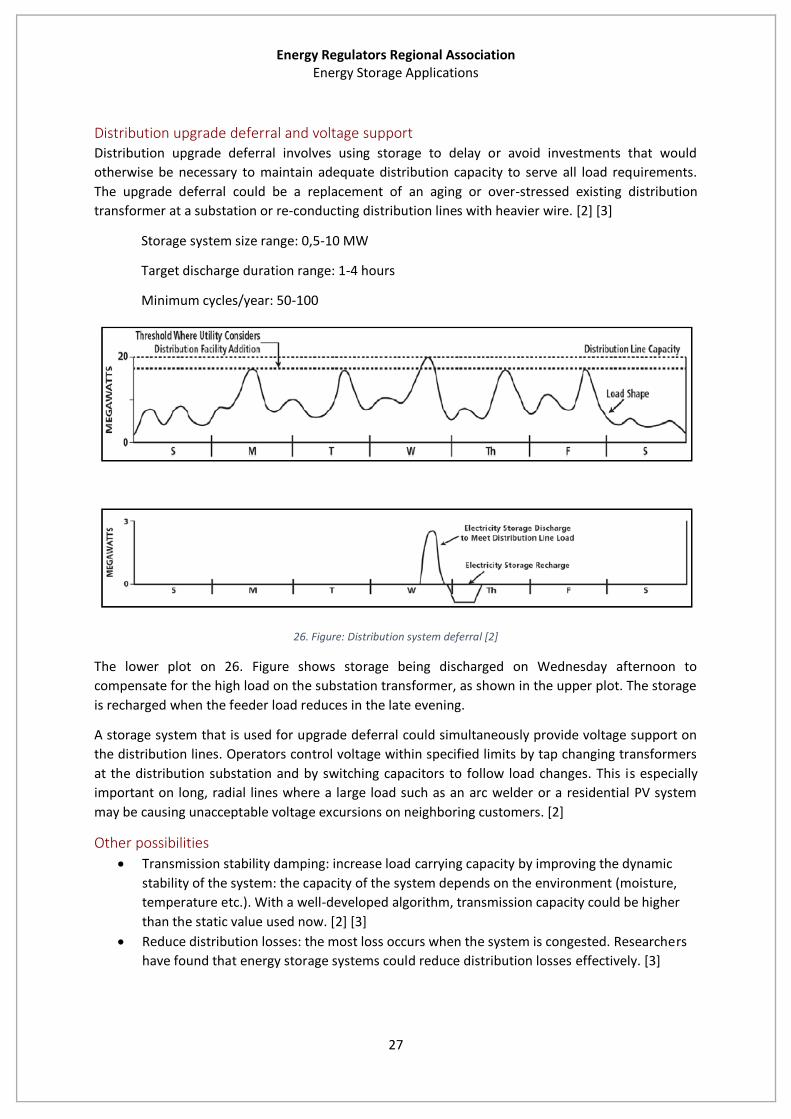
Distribution upgrade deferral and voltage support Distribution upgrade deferral involves using storage to delay or avoid investments that would
otherwise be necessary to maintain adequate distribution capacity to serve all load requirements.
The upgrade deferral could be a replacement of an aging or over-stressed existing distribution
transformer at a substation or re-conducting distribution lines with heavier wire. [2] [3]
Storage system size range: 0,5-10 MW
Target discharge duration range: 1-4 hours
Minimum cycles/year: 50-100
26. Figure: Distribution system deferral [2]
The lower plot on 26. Figure shows storage being discharged on Wednesday afternoon to
compensate for the high load on the substation transformer, as shown in the upper plot. The storage
is recharged when the feeder load reduces in the late evening.
A storage system that is used for upgrade deferral could simultaneously provide voltage support on
the distribution lines. Operators control voltage within specified limits by tap changing transformers
at the distribution substation and by switching capacitors to follow load changes. This is especially
important on long, radial lines where a large load such as an arc welder or a residential PV system
may be causing unacceptable voltage excursions on neighboring customers. [2]
Other possibilities
Transmission stability damping: increase load carrying capacity by improving the dynamic
stability of the system: the capacity of the system depends on the environment (moisture,
temperature etc.). With a well-developed algorithm, transmission capacity could be higher
than the static value used now. [2] [3]
Reduce distribution losses: the most loss occurs when the system is congested. Researchers
have found that energy storage systems could reduce distribution losses effectively. [3]
Energy Regulators Regional Association Energy Storage Applications
28
End-user applications
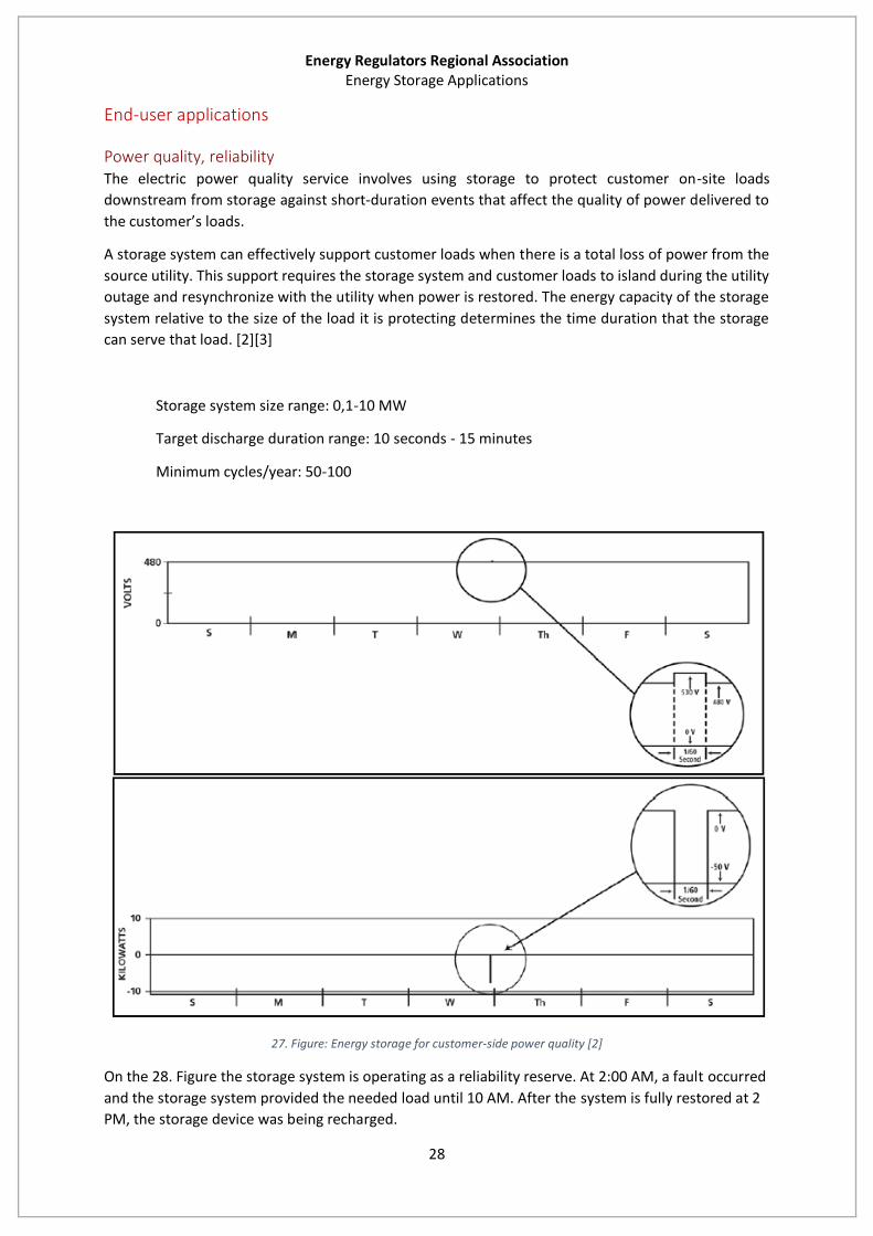
Power quality, reliability The electric power quality service involves using storage to protect customer on-site loads
downstream from storage against short-duration events that affect the quality of power delivered to
the customer’s loads.
A storage system can effectively support customer loads when there is a total loss of power from the
source utility. This support requires the storage system and customer loads to island during the utility
outage and resynchronize with the utility when power is restored. The energy capacity of the storage
system relative to the size of the load it is protecting determines the time duration that the storage
can serve that load. [2][3]
Storage system size range: 0,1-10 MW
Target discharge duration range: 10 seconds - 15 minutes
Minimum cycles/year: 50-100
27. Figure: Energy storage for customer-side power quality [2]
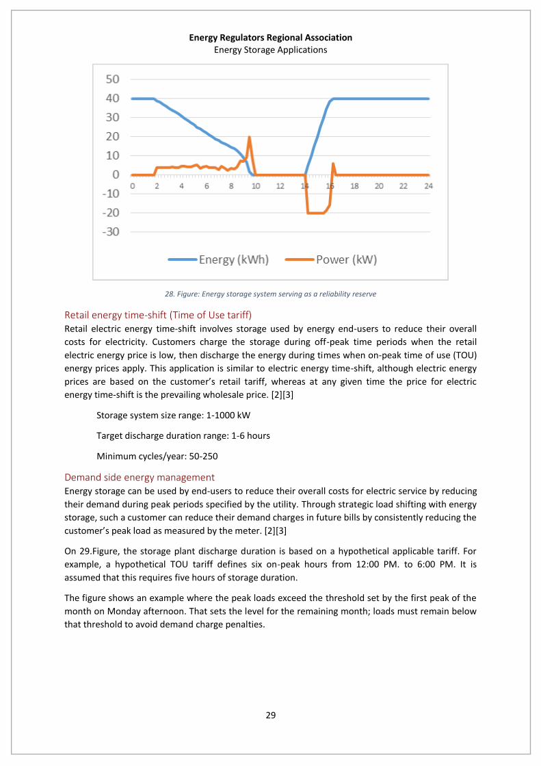
On the 28. Figure the storage system is operating as a reliability reserve. At 2:00 AM, a fault occurred
and the storage system provided the needed load until 10 AM. After the system is fully restored at 2
PM, the storage device was being recharged.
Energy Regulators Regional Association Energy Storage Applications
29
28. Figure: Energy storage system serving as a reliability reserve
Retail energy time-shift (Time of Use tariff) Retail electric energy time-shift involves storage used by energy end-users to reduce their overall
costs for electricity. Customers charge the storage during off-peak time periods when the retail
electric energy price is low, then discharge the energy during times when on-peak time of use (TOU)
energy prices apply. This application is similar to electric energy time-shift, although electric energy
prices are based on the customer’s retail tariff, whereas at any given time the price for electric
energy time-shift is the prevailing wholesale price. [2][3]
Storage system size range: 1-1000 kW
Target discharge duration range: 1-6 hours
Minimum cycles/year: 50-250
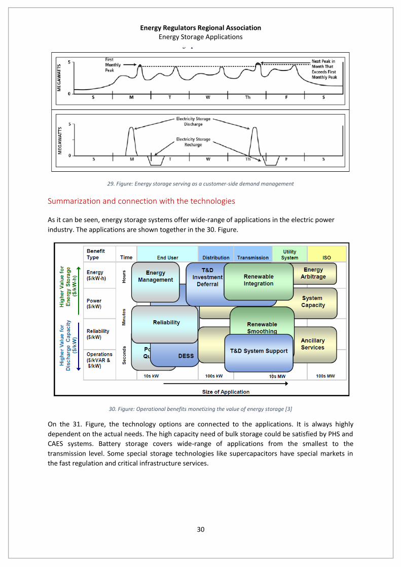
Demand side energy management Energy storage can be used by end-users to reduce their overall costs for electric service by reducing
their demand during peak periods specified by the utility. Through strategic load shifting with energy
storage, such a customer can reduce their demand charges in future bills by consistently reducing the
customer’s peak load as measured by the meter. [2][3]
On 29.Figure, the storage plant discharge duration is based on a hypothetical applicable tariff. For
example, a hypothetical TOU tariff defines six on-peak hours from 12:00 PM. to 6:00 PM. It is
assumed that this requires five hours of storage duration.
The figure shows an example where the peak loads exceed the threshold set by the first peak of the
month on Monday afternoon. That sets the level for the remaining month; loads must remain below
that threshold to avoid demand charge penalties.
Energy Regulators Regional Association Energy Storage Applications
30
29. Figure: Energy storage serving as a customer-side demand management
Summarization and connection with the technologies
As it can be seen, energy storage systems offer wide-range of applications in the electric power
industry. The applications are shown together in the 30. Figure.
30. Figure: Operational benefits monetizing the value of energy storage [3]
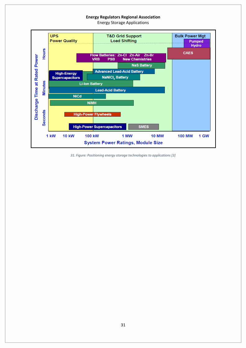
On the 31. Figure, the technology options are connected to the applications. It is always highly
dependent on the actual needs. The high capacity need of bulk storage could be satisfied by PHS and
CAES systems. Battery storage covers wide-range of applications from the smallest to the
transmission level. Some special storage technologies like supercapacitors have special markets in
the fast regulation and critical infrastructure services.
Energy Regulators Regional Association Energy Storage Applications
31
31. Figure: Positioning energy storage technologies to applications [3]
Energy Regulators Regional Association Energy Storage as a Grid Component: Status, Regulatory Issues and Framework
32
Energy Storage as a Grid Component: Status, Regulatory
Issues and Framework
Current situation
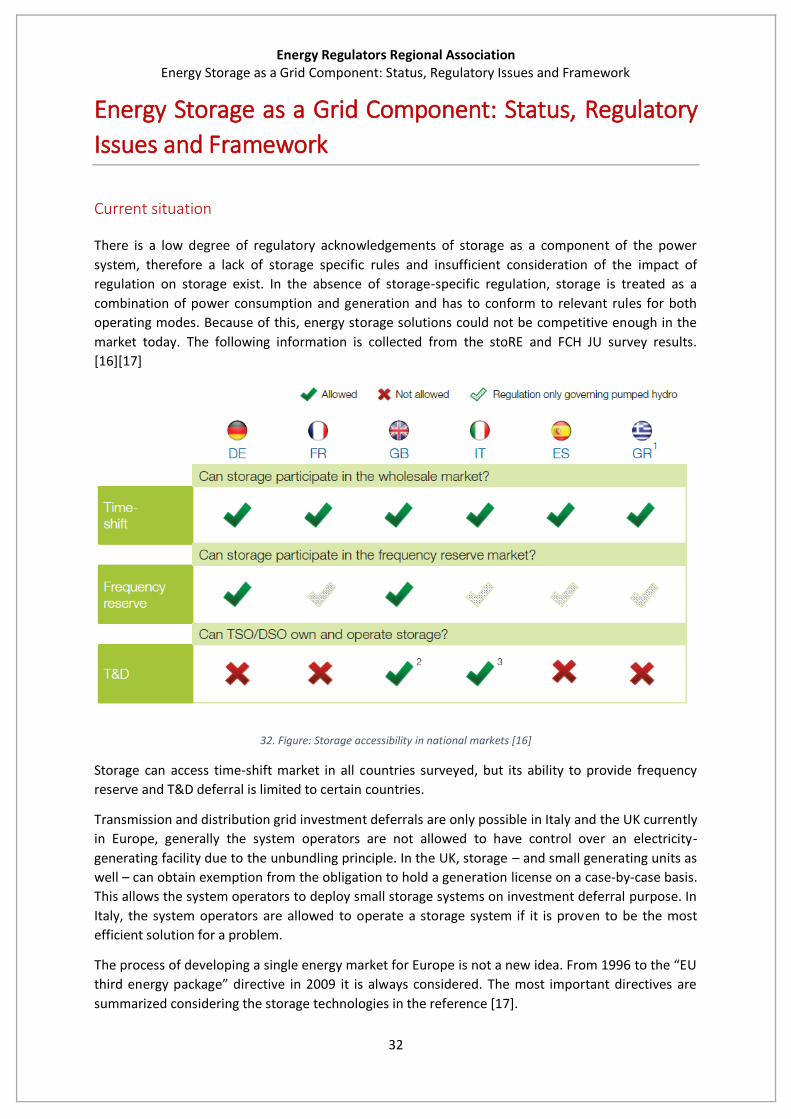
There is a low degree of regulatory acknowledgements of storage as a component of the power
system, therefore a lack of storage specific rules and insufficient consideration of the impact of
regulation on storage exist. In the absence of storage-specific regulation, storage is treated as a
combination of power consumption and generation and has to conform to relevant rules for both
operating modes. Because of this, energy storage solutions could not be competitive enough in the
market today. The following information is collected from the stoRE and FCH JU survey results.
[16][17]
32. Figure: Storage accessibility in national markets [16]
Storage can access time-shift market in all countries surveyed, but its ability to provide frequency
reserve and T&D deferral is limited to certain countries.
Transmission and distribution grid investment deferrals are only possible in Italy and the UK currently
in Europe, generally the system operators are not allowed to have control over an electricity-
generating facility due to the unbundling principle. In the UK, storage – and small generating units as
well – can obtain exemption from the obligation to hold a generation license on a case-by-case basis.
This allows the system operators to deploy small storage systems on investment deferral purpose. In
Italy, the system operators are allowed to operate a storage system if it is proven to be the most
efficient solution for a problem.
The process of developing a single energy market for Europe is not a new idea. From 1996 to the “EU
third energy package” directive in 2009 it is always considered. The most important directives are
summarized considering the storage technologies in the reference [17].

Energy Regulators Regional Association Energy Storage as a Grid Component: Status, Regulatory Issues and Framework
33
Historically, large scale electricity storage plants were developed for storing electricity from base
load plants during the night and supplying it during the daytime peak. Most of these plants were
developed before the market liberalization, but they have been able to operate profitably in the
open market based on the spread between off-peak and on-peak prices. The electricity storage
facilities can have additional income streams that vary depending on the EU Member State in which
they are operating. For example, electricity storage facilities can participate in reserve markets,
ancillary services markets and balancing markets. But the revenues from these additional income
streams are not always transparent and it is difficult to foresee how they will develop as they depend
on fast evolving regulatory, market and technical variables.
Accessible researches (for example reference [18]) almost fully agree that at the moment it is
uneconomic to build new PHS plant, the most developed large-scale electricity storage technology.
Within the infrastructure package the possibility of financial support for electricity storage projects is
foreseen, which could contribute towards overcoming the feasibility and financing difficulties
described in the previous paragraph. However, pumped hydro projects are explicitly exempted from
the opportunity to seek this financial support. Some advocate the view that the level-playing field
should be achieved by removing the financial support for any type of electricity storage as it distorts
competition with other options that can offer flexibility to the system. [17]
Regulatory framework
According to the EU Electricity Directive a Transmission System Operator (TSO) cannot have any type
of control over an electricity generation facility. Therefore, to the extent that electricity storage is
treated within the regulatory framework as generation, a TSO cannot have any control over an
electricity storage facility. The intention is to prevent incentives for abusive behavior in the market.
Several stakeholders think that it’s a strict implementation of the unbundling principle because they
believe that it is in line with the open market approach that delivers the most efficient results on a
system level. Also for ancillary services a market based approach is foreseen or should be developed
within the emerging regulatory framework. This group believes that control over both transmission
and storage should be treated the same way as cross-ownership of transmission and generation.
However, there is still legal uncertainty regarding the implementation of the unbundling principle on
energy storage but it has to be officially clarified and an explicit amendment would be preferable
from a legal certainty viewpoint. As mentioned above, a definition of electricity storage within the
Electricity Directive would help to the clarity of the unbundling principle. [17]
Market design
In an ideal electricity market all the required services are well defined and there are transparent,
liquid and competitive markets allowing any entities and technologies to compete for the
opportunity to provide those services. In such a market there would be clear signals to reflect the
increased requirements for flexibility in balancing and ancillary services due to the increased
penetration of intermittent renewable energy. These signals would be interpreted by electricity
storage developers/operators, among others, to design, build and operate their facilities in order to
capitalize on these market opportunities. Constructing an electricity storage facility with faster
response times and increased ability to activate upwards and downwards reserves and provide other
ancillary services involves increased capital cost.
To indicate a possible market failure, one stakeholder mentioned the example of the effect that the
fast growth of PV in some European markets has on the viability of electricity storage. The solar

Energy Regulators Regional Association Energy Storage as a Grid Component: Status, Regulatory Issues and Framework
34
energy is covering peak power during the day resulting in a smaller spread between peak and off-
peak prices, reducing one of the main electricity storage income streams. (33. Figure) [17]
33. Figure: How solar energy might affect storage requirements [17]
Of course there is a risk in any type of investment and this should be borne by the developer, who
will also reap the possible benefits. However, if the risk becomes too high to justify investments
when the lack of infrastructure translates to a market signal, there will not be enough time for the
necessary investments. [17]
Grid fees
One issue that many stakeholders brought to attention was the grid fees that electricity storage
operators have to pay, which in several EU Member States are double as operators pay for being
both consumers and generators. In addition to grid access fees, the connection fee is another issue
where harmonization across Europe and reduction/elimination of the fee would positively affect the
electricity storage devices viability.
Common rules should be applied regarding transmission access fees and use of system fees for
electricity storage systems in order to avoid deployment of an electricity storage facility in one
country with favorable rules in order to provide services in another country with less favorable rules.
[17]
Balancing market
Electricity storage facilities participate in balancing mechanisms in a very effective way, as they have
the ability both to absorb and inject energy to the system. Close monitoring and participation to the
development of the network code on balancing is recommended for all stakeholders that are
interested to see full access for electricity storage facilities to cross border markets. [17]

Energy Regulators Regional Association Energy Storage as a Grid Component: Status, Regulatory Issues and Framework
35
Recommendations for the future
The first step should be to include a clear definition of electricity storage and use this properly.
Ensure the functioning of an open, fair and transparent market, by introducing clear
restrictions to the use of electricity storage facilities by system operators if and when they
are allowed some kind of control over them
Facilitate the market selection of the most efficient solution when a decision has to be taken
for transmission vs. storage
The financial support for transmission infrastructure and for certain storage technologies is
also not a market tool and adds distortions to the market based evaluation of storage
projects
The procurements of ancillary services is often based on bilateral contracts, with terms and
conditions not publicly available, which does not contribute to the development of an open
market
Large scale storage systems have development times that can be over 10 years long,
therefore for storage requirements in period 2020 - 2030, reliable markets signals should be
available now
Developing guidelines for Cost Benefit Analysis (CBA) and incentivizing pilot projects is a step to
gather more information about commercially working installations. Common rules should be
implemented and defined to avoid further problems. The stoRE project’s (listed as reference [17])
conclusion was that topics listed above (grid fees, balancing, unbundling, definitions and rules)
should be introduced to directives. [17]

Energy Regulators Regional Association Conclusions
36
Conclusions
The increasing role of variable renewable sources (such as wind and solar) in the electricity system
has prompted concerns about grid/system reliability and raised the question of how much these
resources can contribute before enabling technologies such as energy storage are needed.
Fundamentally, this question is overly simplistic. In reality, the question is an economic issue: It
involves the integration costs of variable generation and the amount of various storage or other
enabling technologies that are economically viable in a future with high penetrations of renewable
energy sources. It is clear that high penetration of variable generation increases the need for all
flexibility options including storage, and it also creates market opportunities for these technologies.
Historically, storage has been difficult to sell into the market, not only due to high costs, but also
because of the array of services it provides and the challenges it has in quantifying the value of these
services – particularly the operational benefits such as ancillary services. [1]
The provision of the European infrastructure package to provide financial support for electricity
storage projects could help in the timely development of storage infrastructure. A market oriented
approach that would ensure fair remuneration and would give clear prospects of the electricity
storage facilities profitability. Government support has been a key driver for demonstration projects
all over the world, and these have built a productive foundation of operational knowledge, data and
industry participation so incentivizing the pilot projects is important. Giving a regulatory status to
energy storage that clearly differentiates it from energy generators and energy users is a common
issue. Storage applications could serve stakeholders but market models, roles and responsibilities
should be defined clearly. [10][17][6]
Energy storage system applications should be seen as part of the development of a smarter
electricity system. The decentralized structure needs a two-way grid for optimum operation. A
holistic approach considering all costs and benefits is needed in order to achieve energy targets and
smoothly integrate renewable energy sources into a smart electricity system. [7]
Battery storage in the power sector needs to overcome many barriers before it can be integrated as
a mainstream option. One barrier is the lack of monetary compensations schemes available for the
benefits of battery storage systems. Cost competitiveness, validated performance and in some case
safety issues are also have to be solved before battery can be seen as a real solution for wide range
of applications mentioned before. Adequately adjusted regulatory environment could assist
deployment of storage technologies. Similarly, general lack of industry acceptance is also a barrier.
[10]
In order to reduce public opposition to large energy storage projects, especially pumped hydro,
campaigns for the information of the public about the role of bulk energy storage should be
developed, while the local population should be involved at an early stage before the development
of new projects. [6]
Energy storage technologies have the potential to support our energy system’s evolution, but
realizing this potential will require government, regulator, industry, academia and financial
stakeholders to work together to help overcome existing barriers. It is not the holy grail of the power
grid (as referred in chapter 1), but the variety of solutions must be considered in the future. [4]

Energy Regulators Regional Association Appendix: Reference Installations of NGK
37
Appendix: Reference Installations of NGK

Time
Load / Generation
Frequency
Electricity usage
Fluctuation of electricity usage
Fluctuation of wind power or solar power
adjustment of generation
Generation
With NAS system
Without NAS system
ーO+
ApplicationReference Installations
Peak Reduction and Backup Reserve1MW/7.2MWh NAS system at Yoho National ParkBC Hydro and Power Authority
Stabilization of Huge Wind Farm34MW/244.8MWh NAS system alongside 51MW wind farmFutamata Wind Development Co., Ltd.
Maximization Renewable Energy Installations in Oki Islands4.2MW/25.2MWhChugoku Electric Power Co Inc
British Columbia, CANADA(Operation since 2013)
Aomori Prefecture, Japan(Operation since 2008)
Shimane Prefecture, Japan(Operation since 2015)
A NAS system supplies clean backup power to a remote area in the Canadian Rockies during outages.
Ancillary Services
Investment Deferral
A NAS system absorbs large fluctuations of solar and wind power, which helped Chugoku Electric add more renewables to their grid.
A NAS system makes wind output dispatchable by charging from excess wind power and discharging so as to meet desired dispatch levels. Immediate smoothing and timeshifting can both be provided.
Imbalance between demand and supply could cause frequency fluctuation. NAS can achieve minimization of frequency fluctuation by utilizing its high-speed response.
Renewable StabilizationBy absorbing fluctuating renewable energy such as wind and solar during off-peak times, a NAS system can provide additional power during periods of peak demand.
Fossil Peaker Plant ReplacementA NAS system can provide resource adequacy capacity of 6 hours or more per day, providing a green alternative to a fossil peaker plant. The same NAS system can also provide onpeak/offpeak price arbitrage, frequency regulation, ramping services, VAR support and other grid functions.
NAS systems can defer or eliminate the need for transmission and distribution upgrades. Power can be imported into a transmission constrained area when loads are light, charging a NAS system that is positioned near the load. During peak load, the NAS system is discharged to supplement the power from the at-capacity transmission lines.
0 12 24
Time
Time
Power
Power
Power
Constant output of wind power
Output from wind
Output from solar Combined output
Charging
Combined
Time shift of solar power
0 12 24
0 12 24
Peak-Cut(discharging)
Charging at night
charge & dischargeenergy from NAS
Time
Time
Charge Charge
Discharge
Renewables / Power Plants Transmission,Substation & Distribution
DischargingCharging
Discharging
OVRUVROFRUFROCR
AC/DC Converter
200kW Container(Master)
PCS
NAS Battery
200kW Container(Slave)
200kW Container(Slave)
Aux. Transformer3φ3W 300kVA11kV/410̃480V
Typical Single Line Diagram for 1.6MW NAS Battery System
NAS Controller
NAS Controller
200kW Container(Slave)
Transformer
3φ11kV
800kW NAS UnitX 2
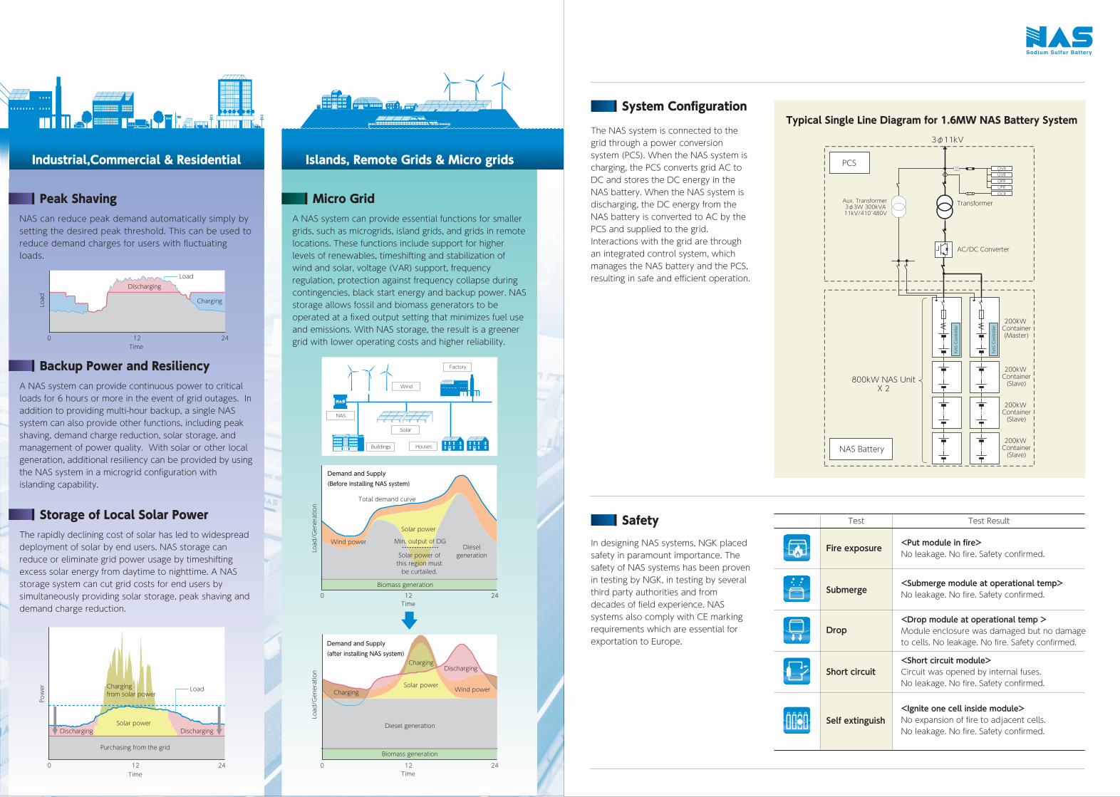
Demand and Supply(Before installing NAS system)
Demand and Supply(after installing NAS system)
Total demand curve
Wind power
Solar power
Min. output of DG
Solar power ofthis region mustbe curtailed.
Charging
Solar power
Diesel generation
Biomass generation
Charging
Discharging
Wind power
Dieselgeneration
Biomass generation
NAS
Wind
Factory
Solar
HousesBuildings
The NAS system is connected to the grid through a power conversion system (PCS). When the NAS system is charging, the PCS converts grid AC to DC and stores the DC energy in the NAS battery. When the NAS system is discharging, the DC energy from the NAS battery is converted to AC by the PCS and supplied to the grid. Interactions with the grid are through an integrated control system, which manages the NAS battery and the PCS, resulting in safe and efficient operation.
<Put module in fire>No leakage. No fire. Safety confirmed.
In designing NAS systems, NGK placed safety in paramount importance. The safety of NAS systems has been proven in testing by NGK, in testing by several third party authorities and from decades of field experience. NAS systems also comply with CE marking requirements which are essential for exportation to Europe.
Peak Shaving
Backup Power and Resiliency
Storage of Local Solar Power
System Configuration
Safety
NAS can reduce peak demand automatically simply by setting the desired peak threshold. This can be used to reduce demand charges for users with fluctuating loads.
Micro GridA NAS system can provide essential functions for smaller grids, such as microgrids, island grids, and grids in remote locations. These functions include support for higher levels of renewables, timeshifting and stabilization of wind and solar, voltage (VAR) support, frequency regulation, protection against frequency collapse during contingencies, black start energy and backup power. NAS storage allows fossil and biomass generators to be operated at a fixed output setting that minimizes fuel use and emissions. With NAS storage, the result is a greener grid with lower operating costs and higher reliability.
A NAS system can provide continuous power to critical loads for 6 hours or more in the event of grid outages. In addition to providing multi-hour backup, a single NAS system can also provide other functions, including peak shaving, demand charge reduction, solar storage, and management of power quality. With solar or other local generation, additional resiliency can be provided by using the NAS system in a microgrid configuration with islanding capability.
The rapidly declining cost of solar has led to widespread deployment of solar by end users. NAS storage can reduce or eliminate grid power usage by timeshifting excess solar energy from daytime to nighttime. A NAS storage system can cut grid costs for end users by simultaneously providing solar storage, peak shaving and demand charge reduction.
0 12 24Time
Charging
DischargingLoad
Load/Generation
Load/Generation
Load
0 12 24Time
0 12 24Time
0 12 24Time
<Submerge module at operational temp>No leakage. No fire. Safety confirmed.
<Drop module at operational temp >Module enclosure was damaged but no damage to cells. No leakage. No fire. Safety confirmed.
<Short circuit module>Circuit was opened by internal fuses.No leakage. No fire. Safety confirmed.
<Ignite one cell inside module>No expansion of fire to adjacent cells. No leakage. No fire. Safety confirmed.
Test
Fire exposure
Submerge
Drop
Short circuit
Self extinguish
Test Result
Industrial,Commercial & Residential
Power Chargingfrom solar power
Solar power
Purchasing from the grid
Discharging Discharging
Load
Islands, Remote Grids & Micro gridsOVRUVROFRUFROCR
AC/DC Converter
200kW Container(Master)
PCS
NAS Battery
200kW Container(Slave)
200kW Container(Slave)
Aux. Transformer3φ3W 300kVA11kV/410̃480V
Typical Single Line Diagram for 1.6MW NAS Battery System
NAS Controller
NAS Controller
200kW Container(Slave)
Transformer
3φ11kV
800kW NAS UnitX 2
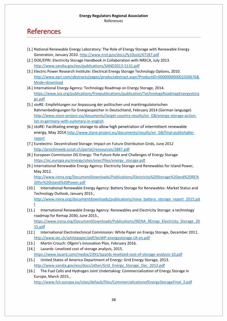
Energy Regulators Regional Association References
38
References
[1.] National Renewable Energy Laboratory: The Role of Energy Storage with Renewable Energy
Generation, January 2010. http://www.nrel.gov/docs/fy10osti/47187.pdf
[2.] DOE/EPRI: Electricity Storage Handbook in Collaboration with NRECA, July 2013.
http://www.sandia.gov/ess/publications/SAND2013-5131.pdf
[3.] Electric Power Research Institute: Electrical Energy Storage Technology Options, 2010.
http://www.epri.com/abstracts/pages/productabstract.aspx?ProductID=000000000001020676&
Mode=download
[4.] International Energy Agency: Technology Roadmap on Energy Storage, 2014.
https://www.iea.org/publications/freepublications/publication/TechnologyRoadmapEnergystora
ge.pdf
[5.] stoRE: Empfehlungen zur Anpassung der politischen und marktregulatorischen
Rahmenbedingungen für Energiespeicher in Deutschland, February 2014 (German language)
http://www.store-project.eu/documents/target-country-results/en_GB/energy-storage-action-
list-in-germany-with-summary-in-english
[6.] stoRE: Facilitating energy storage to allow high penetration of intermittent renewable
energy, May 2014.http://www.store-project.eu/documents/results/en_GB/final-publishable-
report
[7.] Eurelectric: Decentralized Storage: Impact on Future Distribution Grids, June 2012
http://proclimweb.scnat.ch/portal/ressources/2887.pdf
[8.] European Commission DG Energy: The Future Role and Challenges of Energy Storage
https://ec.europa.eu/energy/sites/ener/files/energy_storage.pdf
[9.] International Renewable Energy Agency: Electricity Storage and Renewables for Island Power,
May 2012.
http://www.irena.org/DocumentDownloads/Publications/Electricity%20Storage%20and%20RE%
20for%20Island%20Power.pdf
[10.] International Renewable Energy Agency: Battery Storage for Renewables: Market Status and
Technology Outlook, January 2015.,
http://www.irena.org/documentdownloads/publications/irena_battery_storage_report_2015.pd
f
[11.] International Renewable Energy Agency: Renewables and Electricity Storage: a technology
roadmap for Remap 2030, June 2015.,
https://www.irena.org/DocumentDownloads/Publications/IRENA_REmap_Electricity_Storage_20
15.pdf
[12.] International Electrotechnical Commission: White Paper on Energy Storage, December 2011.
http://www.iec.ch/whitepaper/pdf/iecWP-energystorage-LR-en.pdf
[13.] Martin Crouch: Ofgem’s Innovation Plan, February 2016.
[14.] Lazards: Levelized cost of storage analysis, 2015.
https://www.lazard.com/media/2391/lazards-levelized-cost-of-storage-analysis-10.pdf
[15.] United States of America Department of Energy: Grid Energy Storage, 2013.
http://www.sandia.gov/ess/docs/other/Grid_Energy_Storage_Dec_2013.pdf
[16.] The Fuel Cells and Hydrogen Joint Undertaking: Commercialization of Energy Storage in
Europe, March 2015.,
http://www.fch.europa.eu/sites/default/files/CommercializationofEnergyStorageFinal_3.pdf
Energy Regulators Regional Association References
39
[17.] stoRE: European Regulatory and Market Framework for Electricity Storage Infrastructure,
2013., http://www.store-project.eu/documents/results/en_GB/european-regulatory-and-
market-framework-for-electricity-storage-infrastructure
[18.] Bernardo Rangoni: A Contribution on the Regulation of Electricity Storage: the case of Hydro-
Pumped Storage in Italy and Spain,
http://www.city.ac.uk/__data/assets/pdf_file/0009/120015/Bernardo_RANGONI_electricity-
storage.pdf
[19.] NGK Insulators LTD.: Sodium Sulfur Battery Energy Storage Systems, 2016.,
https://www.ngk.co.jp/nas/why/
[20.] Emeka Okafor (American Electric Power): Dynamic Islanding: Improving Electric Service
Reliability with Energy Storage, 2010.
[21.] Jon Eric Thalman (PG&E), Robert Schainker (EPRI): PG&E’s NAS Battery Demonstration
Projects, 2014.