pae ig idica itu 402 / 412 - bamo · pae ig idica itu 402 / 412 mes 222-03 /1 pae ig idica itu 402...
TRANSCRIPT

Pa
ne
l m
ou
nti
ng
in
dic
ato
r
ITU
40
2 /
41
2IT
U 4
02
/ 4
12
02
-06
-20
15
22
2 M
1 0
3 B
ME
S
222-0
3/1
Pan
el
mo
un
tin
g i
nd
icato
r
ITU
40
2 /
41
2IT
U 4
02
/ 4
12
INS
TR
UC
TIO
NS
MA
NU
AL

10
0
90
80
70
60
50
40
30
20
10
0
10
2
0
30
4
0
50
6
0
70
8
0
90
1
00 t
O�
N.O
.O
� N
.O.
On N
.O.
On N
.C.O
n N.C.
O�
N.C.
10
0
90
80
70
60
50
40
30
20
10
0
10
2
0
30
4
0
50
6
0
70
8
0
90
1
00 t
O�
N.O
.O
� N
.O.
On N
.O.
On N
.C.O
n N.C.
O�
N.C.
5
Graphic depiction of the relay function setpoint
Relay units
Relay units
Setpoint = 5
0
Hysteresis =
10
Hysteresis =
10
Setpoint = 5
0
Relay action: Increasing
Relay action: D
ecreasing
223

CO
NFI
GU
RA
TIO
N /
OP
ER
AT
ING
TH
E
FUN
CT
ION
KE
YS
Doc
umen
tatio
n fo
r ro
utin
g d
iagr
am.
In g
ener
al:
Whe
n co
nfig
urin
g th
e d
isp
lay
you
are
guid
ed t
hrou
gh a
ll p
aram
eter
s, y
ou c
an
choo
se t
he s
ettin
gs w
hich
fit
the
app
licat
ion.
For
eac
h m
enu
ther
e is
a s
crol
-lin
g he
lp t
ext
whi
ch is
aut
omat
ical
ly s
how
n in
the
dis
pla
y, t
his
star
ts a
fter
5
seco
nds
if no
key
has
bee
n ac
tivat
ed.
Con
figur
atio
n is
car
ried
out
by
usin
g th
e 3
func
tion
keys
.
w
illin
crea
se t
he n
umer
ical
val
ue o
r ch
oose
the
nex
t p
aram
eter
.
will
dec
reas
e th
e nu
mer
ical
val
ue o
r ch
oose
the
pre
viou
s p
aram
eter
.
w
ill a
ccep
t th
e ch
osen
val
ue a
nd e
nd t
he m
enu.
If a
func
tion
doe
s no
t ex
ist
in t
he d
isp
lay
all p
aram
eter
s ar
e sk
ipp
ed t
o m
ake
the
conf
igur
atio
n as
sim
ple
as
pos
sib
le.
Onc
e th
e co
nfig
urat
ion
has
bee
n en
tere
d t
he d
isp
lay
will
sho
w “
----
”.
Pre
ssin
g an
d h
old
ing
will
ret
urn
to t
he p
revi
ous
men
u or
ret
urn
to t
he d
efau
lt st
ate
(1.0
) with
out
savi
ng t
he c
hang
ed v
alue
s or
par
amet
ers.
If no
key
is a
ctiv
ated
for
2 m
inut
es,
the
dis
pla
y w
ill r
etur
n to
the
def
ault
stat
e (1
.0) w
ithou
t sa
ving
the
cha
nged
val
ues
or p
aram
eter
s.
Furt
her
exp
lana
tio
ns:
Fast
set
po
int
adju
stm
ent
and
rel
ay t
est:
The
se m
enus
allo
w y
ou t
o ch
ange
th
e se
t p
oint
qui
ckly
and
to
chec
k th
e op
erat
ion
of t
he r
elay
s.
Pre
ssin
g a
nd
at t
he s
ame
time
will
cha
nge
the
stat
e of
the
rel
ay –
thi
s ch
ange
is in
dic
ated
by
the
dio
des
on
the
dis
pla
y. P
ress
ing
will
sav
e th
e se
t p
oint
ch
ange
.
Hol
din
g d
own
for
mor
e th
an 0
.5 s
econ
ds
will
ret
urn
the
unit
to t
he d
efau
lt st
ate
with
out
chan
ging
the
set
poi
nt.
Pas
swo
rd p
rote
ctio
n:U
sing
a p
assw
ord
will
sto
p a
cces
s to
the
men
u an
d p
aram
eter
s. T
here
are
tw
o le
vels
of
pas
swor
d p
rote
ctio
n. P
assw
ord
s b
etw
een
0000
…49
99 a
llow
acc
ess
to t
he f
ast
set
poi
nt a
dju
stm
ent
and
rel
ay t
est.
(Usi
ng t
his
pas
swor
d s
top
s ac
cess
to
all o
ther
par
ts o
f th
e m
enu)
. P
assw
ord
s b
etw
een
5000
…99
99 s
top
ac
cess
to
all p
arts
of
the
men
u, f
ast
set
poi
nt a
nd r
elay
tes
t. (C
urre
nt s
et
poi
nt is
stil
l sho
wn)
. B
y us
ing
the
mas
ter
pas
swor
d 2
008,
all
conf
igur
atio
n m
enus
are
ava
ilab
le.
G
TAB
LE O
F C
ON
TE
NT
S
War
ning
s ...
......
......
......
......
......
......
......
......
......
......
......
......
. 24
Saf
ety
inst
ruct
ions
......
......
......
......
......
......
......
......
......
......
..
25Fr
ont
and
bac
k la
yout
.....
......
......
......
......
......
......
......
......
...
28A
pp
licat
ions
.....
......
......
......
......
......
......
......
......
......
......
......
. 29
Tech
nica
l cha
ract
eris
tics
......
......
......
......
......
......
......
......
....
29M
ount
ing
......
......
......
......
......
......
......
......
......
......
......
......
....
29
Ap
plic
atio
ns ..
......
......
......
......
......
......
......
......
......
......
......
....
30E
lect
rical
sp
ecifi
catio
ns ..
......
......
......
......
......
......
......
......
....
29S
enso
r er
ror
det
ectio
n ...
......
......
......
......
......
......
......
......
....
35C
onne
ctio
ns ..
......
......
......
......
......
......
......
......
......
......
......
...
36B
lock
dia
gram
.....
......
......
......
......
......
......
......
......
......
......
...
37R
outin
g d
iagr
am ..
......
......
......
......
......
......
......
......
......
......
...
38S
crol
ling
help
tex
t ....
......
......
......
......
......
......
......
......
......
....
40C
onfig
urat
ion
/ op
erat
ing
the
func
tion
keys
.....
......
......
.....
42
Gra
phi
c d
epic
tion
of t
he r
elay
fun
ctio
n se
tpoi
nt .
......
......
. 43
22
3
4 5 8 9 9 9
10
11
15
16
17
18
20
22
23

REL1
SET
-->
ENTER
RELAY 1
SETUP
SKIP
-->
SKIP R
ELAY 1 SETU
P O
FF -->
R
ELAY 1 D
ISAB
LED
SETP
xxxx
-->
RELAY SETPO
INT
A
CT1
INCR
-->
A
CTIVATE AT INCR
EASIN
G SIG
NA
L D
ECR
-->
ACTIVATE AT D
ECREA
SING
SIGN
ALL
H
YS1
xxxx -->
R
ELAY HYSTER
ESIS
ERR
1
HO
LD
-->
HO
LD R
ELAY AT ERR
OR
A
CTI -->
A
CTIVATE RELAY AT ER
RO
R
DEA
C -->
D
EACTIVATE R
ELAY AT ERR
OR
N
ON
E -->
U
ND
EFINED
STATUS AT ER
RO
R
O
N.D
E
xxxx
-->
RELAY O
N-D
ELAY IN SECO
ND
S
OF.D
E
xxxx
-->
RELAY O
FF-DELAY IN
SECON
DS
R
EL2
SET -->
EN
TER R
ELAY 2 SETU
P SK
IP -->
SK
IP RELAY 2
SETUP
OFF
-->
RELAY 2
DISA
BLED
SETP
xxxx -->
R
ELAY SETPOIN
T
ACT2
IN
CR
-->
ACTIVATE AT IN
CREA
SING
SIGN
AL
DECR
-->
A
CTIVATE AT DECR
EASIN
G SIG
NA
L
HYS2
xxxx
-->
RELAY H
YSTERESIS
ER
R2
H
OLD
-->
H
OLD
RELAY AT ER
RO
R
ACTI
-->
ACTIVATE R
ELAY AT ERR
OR
D
EAC
-->
DEA
CTIVATE RELAY AT ER
RO
R
NO
NE
-->
UN
DEFIN
ED STATU
S AT ERR
OR
ON
.DE
xxxx -->
R
ELAY ON
-DELAY IN
SECON
DS
O
F.DE
xxxx -->
R
ELAY OFF-D
ELAY IN SECO
ND
S
A.O
UT
0-2
0
-->
OU
TPUT R
AN
GE IN
mA
4
-20
-->
O
UTPU
T RA
NG
E IN m
A
20
-0
-->
OU
TPUT R
AN
GE IN
mA
2
0-4
-->
O
UTPU
T RA
NG
E IN m
A
O
.LO
xxxx -->
D
ISPLAY VALU
E FOR
OU
TPUT LO
W
O
.HI
xxxx -->
D
ISPLAY VALU
E FOR
OU
TPUT H
IGH
O.ER
R
23
mA
-->
N
AM
UR
NE4
3 U
PSCALE AT ER
RO
R
3,5
mA
-->
NA
MU
R N
E43
DO
WN
SCALE AT ER
RO
R
0m
A
-->
DO
WN
SCALE AT ER
RO
R
NO
NE
-->
UN
DEFIN
ED O
UTPU
T AT ERR
OR
RESP
xxx.x
-->
AN
ALO
GU
E OU
TPUT R
ESPON
SE TIME
IN SECO
ND
S
E.PAS
NO
-->
EN
AB
LE PASSW
OR
D PR
OTECTIO
N
YES
N.PA
S
xxxx
-->
SELECT NEW
PASSW
OR
D
AD
V M
ENU
: LA
NG
-->
EN
TER LA
NG
UA
GE SETU
P D
ISP -->
EN
TER D
ISPLAY SETUP
CAL
-->
PERFO
RM
PRO
CESS CALIB
RATIO
N
HLP.T
DE
-->
DE - W
AEH
LE DEU
TSCHEN
HILFETEX
T D
K
-->
DK
- VAELG
DA
NSK
HJA
ELPETEKST
ES -->
ES - SELECCIO
NA
R TEX
TO D
E
AYU
DA
EN ESPA
NO
L FR
-->
FR
- SELECTION
TEXTE D
’AID
E
EN
FRA
NCA
IS IT
-->
IT - SELEZION
AR
E TESTI DI
AIU
TO ITA
LIAN
I SE
-->
SE - VALJ SV
ENSK
HJA
LPTEXT
UK
-->
U
K - SELECT EN
GLISH
HELPTEX
T CZ
-->
CZ - VYB
ER CESKO
U N
APO
VED
U
LIGH
xxxx
-->
AD
JUST D
ISPLAY LIGH
T INTEN
SITY CA
.LO
YES -->
CA
LIBR
ATE INPU
T LOW
TO PR
OCESS
VALU
E? N
O
CA
.HI
YES -->
CA
LIBR
ATE INPU
T HIG
H TO
PRO
CESS
VA
LUE?
NO
VA
L.L
xxxx
-->
SET VALU
E FOR
LOW
CALIB
RATIO
N
POIN
T
VA
L.H
xxxx -->
SET VA
LUE FO
R H
IGH
CALIB
RATIO
N
POIN
T U
SE.C
YES
-->
USE PR
OCESS CA
LIBR
ATED VA
LUES?
NO
SY
MB
OL ID
EN
TIFIC
AT
ION
Triangle w
ith an exclamatio
n mark: W
arning / dem
and. P
otentially lethal situations. T
he CE
mark p
roves the comp
liance of the mod
ule with the essential
requirem
ents of the directives. W
AR
NIN
G!
This mod
ule is designed
for connection to hazardous electric
voltages. Ignoring this warning can result in severe p
ersonal injury or m
echanical dam
age. To avoid the risk of electric shock
and fire, the safety instructions of this m
anual must b
e observed
and
the guidelines follow
ed. The sp
ecifications must not b
e exceed
ed, and
the mod
ule must only b
e app
lied as d
escribed
in the follow
ing. Prior to the com
missioning of the m
odule, this
manual m
ust be exam
ined carefully. O
nly qualified
personnel
(technicians) should install this m
odule.
If the equip
ment is used
in a manner not sp
ecified b
y the m
anufacturer, the protection p
rovided
by the eq
uipm
ent may b
e im
paired
.
WA
RN
ING
!
Until the m
odule is fixed
, do not connect hazard
ous voltages to the m
odule.
The following op
erations should only b
e carried out on a
disconnected
mod
ule and und
er ES
D safe cond
itions:Troub
leshooting the mod
ule.
Rep
air of the m
od
ule must b
e do
ne by the m
anufacturer.
GE
NE
RA
L
HA
ZA
RD
- O
US
VOLTA
GE
421

SA
FET
Y I
NS
TR
UC
TIO
NS
DE
FIN
ITIO
NS
:H
azar
dou
s vo
ltage
s ha
ve b
een
def
ined
as
the
rang
es:
75 t
o 15
00 V
olt
DC
, an
d
50 t
o 10
00 V
olt
AC
.Te
chni
cian
s ar
e q
ualif
ied
per
sons
ed
ucat
ed o
r tr
aine
d t
o m
ount
, op
erat
e, a
nd
also
tro
uble
shoo
t te
chni
cally
cor
rect
and
in a
ccor
dan
ce w
ith s
afet
y re
gula
tions
.O
per
ator
s, b
eing
fam
iliar
with
the
con
tent
s of
thi
s m
anua
l, ad
just
and
op
erat
e th
e kn
obs
or p
oten
tiom
eter
s d
urin
g no
rmal
op
erat
ion.
RE
CE
IPT
AN
D U
NPA
CK
ING
:U
npac
k th
e d
evic
e w
ithou
t d
amag
ing
it. T
he p
acki
ng s
houl
d a
lway
s fo
llow
the
d
evic
e un
til t
his
has
bee
n p
erm
anen
tly m
ount
ed.
Che
ck a
t th
e re
ceip
t of
the
d
evic
e w
heth
er t
he t
ype
corr
esp
ond
s to
the
one
ord
ered
.
EN
VIR
ON
ME
NT:
Avo
id d
irect
sun
light
, d
ust,
hig
h te
mp
erat
ures
, m
echa
nica
l vib
ratio
ns a
nd s
hock
, as
wel
l as
rain
and
hea
vy m
oist
ure.
If n
eces
sary
, he
atin
g in
exc
ess
of t
he s
tate
d
limits
for
am
bie
nt t
emp
erat
ures
sho
uld
be
avoi
ded
by
way
of
vent
ilatio
n.A
ll m
odul
es f
all u
nder
Inst
alla
tion
Cat
egor
y II,
Pol
lutio
n D
egre
e 1,
and
Insu
latio
n C
lass
II.
MO
UN
TIN
G:
Onl
y te
chni
cian
s w
ho a
re f
amili
ar w
ith t
he t
echn
ical
ter
ms,
war
ning
s, a
nd
inst
ruct
ions
in t
he m
anua
l and
who
are
ab
le t
o fo
llow
the
se s
houl
d c
onne
ct t
he
mod
ule.
S
houl
d t
here
be
any
dou
bt
as t
o th
e co
rrec
t ha
ndlin
g of
the
mod
ule,
ple
ase
cont
act
us.
Mou
ntin
g an
d c
onne
ctio
n of
the
mod
ule
shou
ld c
omp
ly w
ith n
atio
nal l
egis
latio
n fo
r m
ount
ing
of e
lect
ric m
ater
ials
, i.a
. w
ire c
ross
sec
tion,
pro
tect
ive
fuse
, an
d
loca
tion.
Des
crip
tions
of
Inp
ut /
Out
put
and
sup
ply
con
nect
ions
are
sho
wn
in
the
blo
ck d
iagr
am a
nd s
ide
lab
el.
SCR
OLL
ING
HEL
P T
EXT
Dis
play
in d
efau
lt s
tate
xxx
x, h
ardw
are
erro
r:
SE.B
R
-->
SE
NSO
R W
IRE
BR
EAK
AG
E SE
.SH
--
>
SEN
SOR
SH
ORT
CIR
CUIT
IN
.HI
-->
IN
PUT
OV
ERR
AN
GE
IN.L
O
-->
IN
PUT
UN
DER
RA
NG
E 9
.9.9
.9 -
->
DIS
PLAY
OV
ERR
AN
GE
-1.9
.9.9
--
> D
ISPL
AY U
ND
ERR
AN
GE
HW
.ER
-->
H
AR
DW
AR
E ER
RO
R
EE.E
R
-->
EE
PRO
M E
RR
OR
-
CHEC
K C
ON
FIG
UR
ATIO
N
RA
.ER
--
>
RA
M M
EMO
RY E
RR
OR
CJ
.ER
-
-> C
JC S
ENSO
R E
RR
OR
Fa
stse
t (E
nabl
ed):
F.SE
T
R
EL1
--
>
FAST
SET
MEN
U -
R
EL2
--
>
SELE
CT R
ELAY
SE
TP
xxxx
--
>
REL
AY S
ETPO
INT
- PR
ESS
OK
TO
SAV
E Fa
stse
t (D
isab
led)
: SE
TP
xxxx
--
>
REL
AY S
ETPO
INT
- R
EAD
ON
LY
Conf
igur
atio
n m
enus
: A
DV
YE
S --
>
ENTE
R A
DVA
NCE
D S
ETU
P M
ENU
? N
O
PASS
xx
xx
-->
SE
T CO
RR
ECT
PASS
WO
RD
IN
C.
LIN
* --
>
TEX
T EN
TER
ED B
Y U
SER
IN P
RES
ET
CUR
R
-->
CU
RR
ENT
INPU
T V
OLT
--
>
VO
LTA
GE
INPU
T
POTM
--
>
POTE
NTI
OM
ETER
INPU
T LI
N.R
--
>
LIN
EAR
RES
ISTA
NCE
INPU
T
TEM
P --
>
TEM
PER
ATU
RE
SEN
SOR
INPU
T
R
AN
G
W
hen
curr
ent
sele
cted
: 0
-20
--
>
INPU
T R
AN
GE
IN m
A
4-2
0
-->
IN
PUT
RA
NG
E IN
mA
RA
NG
Whe
n vo
ltag
e se
lect
ed:
0-1
0
-->
IN
PUT
RA
NG
E IN
VO
LT
2-1
0
-->
IN
PUT
RA
NG
E IN
VO
LT
0.0
-1
-->
IN
PUT
RA
NG
E IN
VO
LT
0.2
-1
-->
IN
PUT
RA
NG
E IN
VO
LT
D
EC.P
1
11
1
-->
D
ECIM
AL
POIN
T PO
SITI
ON
1
11
.1
-->
D
ECIM
AL
POIN
T PO
SITI
ON
1
1.1
1
-->
D
ECIM
AL
POIN
T PO
SITI
ON
1
.11
1
-->
D
ECIM
AL
POIN
T PO
SITI
ON
LR.L
O
xxxx
--
>
SET
RES
ISTA
NCE
VA
LUE
LOW
LR
.HI
xx
xx
-->
SE
T R
ESIS
TAN
CE V
ALU
E H
IGH
D
I.LO
xx
xx
-->
D
ISPL
AY R
EAD
OU
T LO
W
DI.H
I xx
xx
-->
D
ISPL
AY R
EAD
OU
T H
IGH
REL
.U
PER
C --
>
SET
REL
AY IN
PER
CEN
TAG
E D
ISP
-->
SE
T R
ELAY
IN D
ISPL
AY U
NIT
S
TYP
E
CU
--
>
SELE
CT C
U S
ENSO
R T
YPE
PT
-->
SE
LECT
PT
SEN
SOR
TYP
E N
I --
>
SELE
CT N
I SEN
SOR
TYP
E TC
--
>
SELE
CT T
C SE
NSO
R T
YPE
CU.T
Y
10
--
>
SELE
CT C
U S
ENSO
R T
YPE
20
--
>
SELE
CT C
U S
ENSO
R T
YPE
50
--
>
SELE
CT C
U S
ENSO
R T
YPE
10
0
-->
SE
LECT
CU
SEN
SOR
TYP
E
PT.
TY
10
--
>
SELE
CT P
T SE
NSO
R T
YPE
20
--
>
SELE
CT P
T SE
NSO
R T
YPE
50
--
>
SELE
CT P
T SE
NSO
R T
YPE
10
0
-->
SE
LECT
PT
SEN
SOR
TYP
E 2
00
--
>
SELE
CT P
T SE
NSO
R T
YPE
25
0
-->
SE
LECT
PT
SEN
SOR
TYP
E 3
00
--
>
SELE
CT P
T SE
NSO
R T
YPE
40
0
-->
SE
LECT
PT
SEN
SOR
TYP
E 5
00
--
>
SELE
CT P
T SE
NSO
R T
YPE
10
00
--
>
SELE
CT P
T SE
NSO
R T
YPE
N
I.TY
5
0
-->
SE
LECT
NI S
ENSO
R T
YPE
10
0
-->
SE
LECT
NI S
ENSO
R T
YPE
12
0
-->
SE
LECT
NI S
ENSO
R T
YPE
10
00
--
>
SELE
CT N
I SEN
SOR
TYP
E
CON
N
W
hen
Cu, P
t an
d N
i sen
sor
is s
elec
ted
2W
--
>
SELE
CT 2
-WIR
E SE
NSO
R C
ON
NEC
TIO
N
3W
--
>
SELE
CT 3
-WIR
E SE
NSO
R C
ON
NEC
TIO
N
4W
--
>
SELE
CT 4
-WIR
E SE
NSO
R C
ON
NEC
TIO
N
TC
.TY
TC
. B
-->
SE
LECT
TC
SEN
SOR
TYP
E TC
. E
-->
SE
LECT
TC
SEN
SOR
TYP
E TC
. J
-->
SE
LECT
TC
SEN
SOR
TYP
E TC
. K
-->
SE
LECT
TC
SEN
SOR
TYP
E TC
. L
-->
SE
LECT
TC
SEN
SOR
TYP
E TC
. N
-->
SE
LECT
TC
SEN
SOR
TYP
E TC
. R
-->
SE
LECT
TC
SEN
SOR
TYP
E TC
. S
-->
SE
LECT
TC
SEN
SOR
TYP
E TC
. T
-->
SE
LECT
TC
SEN
SOR
TYP
E TC
. U
-->
SE
LECT
TC
SEN
SOR
TYP
E TC
.W3
--
>
SELE
CT T
C SE
NSO
R T
YPE
TC.W
5
-->
SE
LECT
TC
SEN
SOR
TYP
E TC
.LR
--
>
SELE
CT T
C SE
NSO
R T
YPE
D
EC.P
Whe
n te
mpe
ratu
re s
elec
ted
11
11
--
>
DEC
IMA
L PO
INT
POSI
TIO
N
11
1.1
--
>
DEC
IMA
L PO
INT
POSI
TIO
N
UN
IT
°C
-->
D
ISPL
AY A
ND
REL
AY S
ETU
P IN
CEL
SIU
S °F
--
>
DIS
PLAY
AN
D R
ELAY
SET
UP
IN
FAH
REN
HEI
T
20
5

1.5
1.5
1.5
1.7
1.7
1.6
1.6
1.4
AD
V.SET1.8
RO
UTIN
G D
IAG
RA
MIf no keys are activated for 2
minutes the display returns to default state
1.0
without saving configuration changes..
Increase value / choose next parameter
Decrease value / choose previous param
eter A
ccept the chosen parameter and go to the next m
enuH
old B
ack to previous menu / return to m
enu 1.0
without saving
To default state 1.0
The following apply to fixed hazardous voltages-connected devices:
The max. size of the protective fuse is 1
0 A
and, together with a pow
er sw
itch, it should be easily accessible and close to the device. The power
switch should be m
arked with a label telling it w
ill switch off the vol-
tage to the device.
UL IN
STALLATIO
N R
EQU
IREM
ENTS:
For use on a flat surface of a type 1 enclosure
Use 6
0/7
5°C copper conducters only
Enclosure rating (face only)........................... Type 4X
, UL5
0E
Max. am
bient temperature ............................ 6
0°C
Max. w
ire size, pins 41
...46
........................... AW
G 3
0-1
6
Max. w
ire size, others ...................................... AW
G 3
0-1
2
UL file num
ber .................................................... E24
82
56
CALIB
RATIO
N A
ND
AD
JUSTM
ENT:
During calibration and adjustm
ent, the measuring and connection of external
voltages must be carried out according to the specifications of this m
anual. The technician m
ust use tools and instruments that are safe to use.
NO
RM
AL O
PER
ATION
:O
perators are only allowed to adjust and operate devices that are safely fixed in
panels, etc., thus avoiding the danger of personal injury and damage. This m
eans there is no electrical shock hazard, and the device is easily accessible.
CLEAN
ING
:W
hen disconnected, the device may be cleaned w
ith a cloth moistened w
ith distilled w
ater.
LIAB
ILITY:
To the extent the instructions in this manual are not strictly observed, the
custom er cannot advance a dem
and against PR electronics A
/S that would other-
wise exist according to the concluded sales agreem
ent.
619

Pow
er u
p
1.0
1.2
1.1
1.3
1.4
1.4
1.6
AD
V.SE
T
1.0
= D
efau
lt s
tate
1.1
= O
nly
if p
assw
ord-
pr
otec
ted
1.2
= O
nly
is F
astS
et is
ena
bled
1.3
= F
astS
et a
nd re
lay
test
dis
ab-
led
at p
assw
ord
50
00
...9
99
9.
1.4
= N
o re
lay
outp
uts
1.5
= N
ot v
alid
for
the
se in
put
sign
als:
Pot
enti
omet
er, 0
...2
0
mA
and
vol
tage
1.6
= N
o an
alog
ue o
utpu
t1
.7 =
Onl
y if
inpu
t si
gnal
is
tem
pera
ture
1.8
= In
def
ault
sta
te p
ress
and
ho
ld
or
to
chan
ge
disp
lay
inte
nsit
y be
twee
n da
mpe
d an
d fu
ll (7
= f
ull i
nten
sity
).
Fast
set
poin
t ad
just
men
tan
d re
lay
test
Incr
ease
set
poin
t D
ecre
ase
setp
oint
Sav
e an
d ex
it t
he m
enu
and
s
imul
tane
ousl
y =
chan
ge re
lay
stat
e
18
7

I+
Gnd.11
12
31
32
CPUAD
EEPROM
0.2 mA
PTC
20
1 2 3 4
46
45
44
43
42
41
TC+V
4 3 2
2122
23
2425
26
R1
R2
1
3
2
Tx+
+
+
mA
I Output
CommonRelay 1 N.O.
Relay 1 N.C.
CommonRelay 2 N.O.
Relay 2 N.C.
Supply
Supply
21.6...253 VACor
19.2...300 VDC
Version D
Int. CJC
2-wire supply> 15 VDC
Input +, mA
Input gnd.
RTD, wiresPotm.
BLO
CK
DIA
GR
AM
R
Picture 1:
Front
Picture 2: B
ack
817

4-
dig
it 14
-seg
men
t LE
D in
dic
ator
Inp
ut f
or m
A, V
, pot
entio
met
er, R
TD a
nd T
C
2
rela
ys a
nd a
nalo
gue
outp
ut
U
nive
rsal
vol
tage
sup
ply
Fron
t ke
y p
rogr
amm
able
+-
+-
+-
Tx+
-
3132
4142
4344
4546
4142
4344
4546
4142
4344
4546
4142
4344
4546
4142
4344
4546
4142
4344
4546
4142
4344
4546
4142
4344
4546
+-
mA
1112
R2
R1
2122
2324
2526
CO
NN
EC
TIO
NS
RTD
, 2-w
ireR
TD, 3
-wire
RTD
, 4-w
ire
Pot
entio
met
erVo
ltage
TC2-
wire
tra
nsm
itter
Cur
rent
Cur
rent
Rel
ays
Inp
uts:
Out
put
:S
upp
ly:
R
ead
out
at h
ard
war
e er
ror
Err
or s
earc
hR
ead
out
Err
or c
ause
Test
of
inte
rnal
com
mun
icat
ion
uC /
AD
CH
W.E
RP
erm
anen
t er
ror
in A
DC
Test
of
inte
rnal
CJC
sen
sor
CJ.
ER
CJC
sen
sor
def
ect
Che
ck-s
um t
est
of t
he c
onfig
urat
ion
in R
AM
RA
.ER
Err
or in
RA
MC
heck
-sum
tes
t of
the
con
figur
atio
n in
EE
PR
OM
EE
.ER
Err
or in
EE
PR
OM
! Err
or in
dic
atio
ns in
the
dis
pla
y b
link
once
a s
econ
d.
The
help
tex
t ex
pla
ins
the
erro
r.
16
9
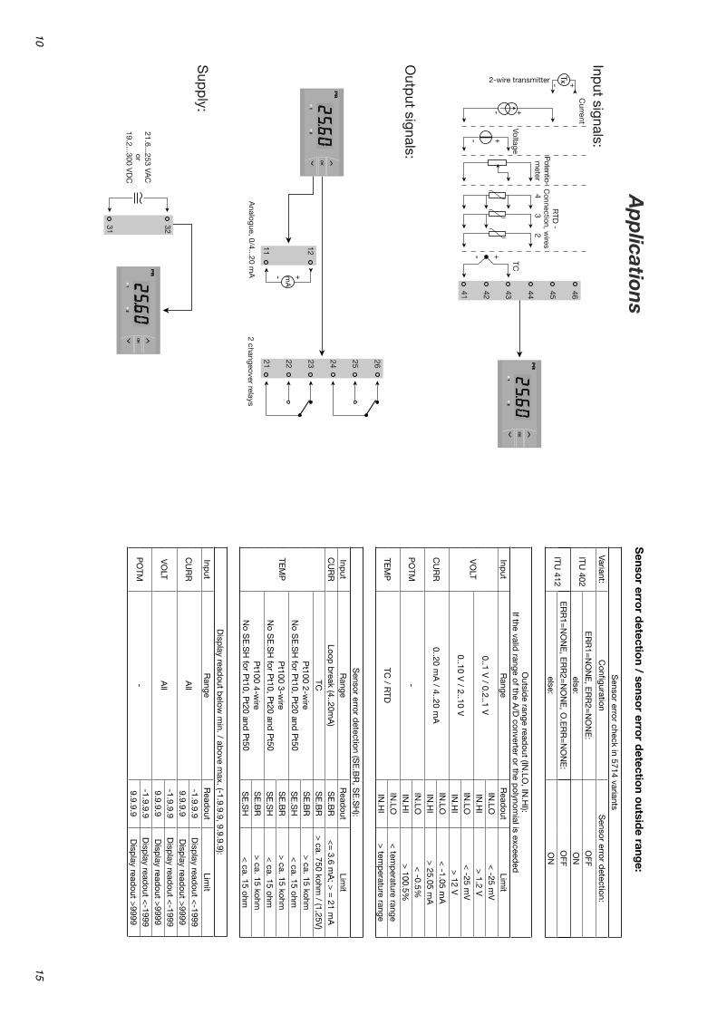
Sensor error check in 5714 variants
Variant:C
onfigurationS
ensor error detection:
ITU 402
ER
R1=
NO
NE
, ER
R2=
NO
NE
:O
FFelse:
ON
ITU 412
ER
R1=
NO
NE
, ER
R2=
NO
NE
, O.E
RR
=N
ON
E:
OFF
else:O
N
Senso
r error d
etection / senso
r error d
etection o
utside rang
e:
Outsid
e range readout (IN
.LO, IN
.HI):
If the valid range of the A
/D converter or the p
olynomial is exceed
edInp
utR
angeR
eadout
Limit
VO
LT0..1 V
/ 0.2..1 VIN
.LO<
-25 mV
IN.H
I>
1.2 V
0..10 V / 2..10 V
IN.LO
< -25 m
VIN
.HI
> 12 V
CU
RR
0..20 mA
/ 4..20 mA
IN.LO
< -1.05 m
AIN
.HI
> 25.05 m
A
PO
TM-
IN.LO
< -0.5%
IN.H
I>
100.5%
TEM
PTC
/ RTD
IN.LO
< tem
perature range
IN.H
I>
temp
erature range
Sensor error d
etection (SE
.BR
, SE
.SH
):
Input
Range
Read
outLim
itC
UR
RLoop
break (4..20m
A)
SE
.BR
<=
3.6 mA
; > =
21 mA
TEM
P
TCS
E.B
R>
ca. 750 kohm / (1,25V
)
Pt100 2-w
ire N
o SE
.SH
for Pt10, P
t20 and P
t50S
E.B
R>
ca. 15 kohmS
E.S
H<
ca. 15 ohm
Pt100 3-w
ire N
o SE
.SH
for Pt10, P
t20 and P
t50S
E.B
R>
ca. 15 kohmS
E.S
H<
ca. 15 ohm
Pt100 4-w
ire N
o SE
.SH
for Pt10, P
t20 and P
t50S
E.B
R>
ca. 15 kohmS
E.S
H<
ca. 15 ohm
Disp
lay readout b
elow m
in. / above m
ax. (-1.9.9.9, 9.9.9.9):
Input
Range
Read
outLim
it
CU
RR
All
-1.9.9.9D
isplay read
out <-1999
9.9.9.9D
isplay read
out >9999
VO
LTA
ll-1.9.9.9
Disp
lay readout <
-19999.9.9.9
Disp
lay readout >
9999
PO
TM-
-1.9.9.9D
isplay read
out <-1999
9.9.9.9D
isplay read
out >9999
+-
12
11
26
25
24
23
22
21
32
31
12
12
+-+-
46
45
44
43
42
41
4 3
2
TC1
2
+-
Ap
plication
s
Input signals:
Current
Potentio-m
eter
Outp
ut signals:
2 changeover relaysA
nalogue, 0/4...20 mA
Sup
ply:
21.6...253 VAC
or
19.2...300 VD
C
Voltage
RTD
-C
onnection, wires
2-wire transmitter
10
15

Ele
ctri
cal s
pec
ifica
tio
ns:
Sp
ecifi
cati
ons
ran
ge:
-20°
C t
o +
60°C
Co
mm
on
spec
ifica
tio
ns:
Sup
ply
vol
tage
, un
iver
sal .
......
......
......
......
... 2
1.6.
..253
VA
C,
50...
60 H
z or
19
.2...
300
VD
CC
onsu
mp
tion
Isol
atio
n vo
ltage
, te
st /
op
erat
ion
......
......
.. 2
.3 k
VAC
/ 2
50 V
AC
Sig
nal-
/ n
oise
rat
io ..
......
......
......
......
......
....
Min
. 60
dB
(0...
100
kHz)
Res
pon
se t
ime
(0...
90 %
, 10
0...1
0 %
), p
rogr
amm
able
:
Tem
per
atur
e in
put
......
......
......
......
......
... 1
...60
s
Cur
rent
/ v
olta
ge in
put
......
......
......
......
.. 0
.4...
60 s
Cal
ibra
tion
tem
per
atur
e....
......
......
......
......
.. 2
0...2
8°C
Acc
urac
y, t
he g
reat
er o
f ge
nera
l and
bas
ic v
alue
s:
Gen
eral
val
ues
In
put
typ
eA
bso
lute
ac
cura
cyTe
mp
erat
ure
coef
ficie
nt
All
±0.
1% o
f re
adin
g ±
0.01
% o
f re
adin
g /
°C
Typ
eIn
tern
al c
onsu
mp
tion
Max
. co
nsum
ptio
n
ITU
402
2.7
W3.
0 W
ITU
412
3.2
W3.
5W
Volt
age
inpu
t:M
easu
rem
ent
rang
e ....
......
......
......
......
......
......
......
.. 0
...1
2 V
DC
Prog
ram
mab
le m
easu
rem
ent
rang
es ...
......
......
0...
1 /
0.2
...1
/
0...
10
/ 2
...1
0 V
DC
Inpu
t re
sist
ance
......
......
......
......
......
......
......
......
......
.. N
om. 1
0 M
Out
puts
:D
ispl
ay:
Dis
play
rea
dout
......
......
......
......
......
......
......
......
......
... -
19
99
...9
99
9 (4
dig
its)
D
ecim
al p
oint
......
......
......
......
......
......
......
......
......
......
. Pr
ogra
mm
able
D
igit
hei
ght .
......
......
......
......
......
......
......
......
......
......
... 1
3.8
mm
D
ispl
ay u
pdat
ing
......
......
......
......
......
......
......
......
......
2.2
tim
es /
s
Inpu
t ou
tsid
e in
put
rang
e is
indi
cate
d by
......
......
......
......
......
......
......
......
......
......
....
Expl
anat
ory
text
Curr
ent
outp
ut:
Sign
al ra
nge
(spa
n) ...
......
......
......
......
......
......
......
....
0...
20
mA
Pr
ogra
mm
able
sig
nal r
ange
s ....
......
......
......
......
... 0
...2
0 /
4...
20
/
20
...0
/ 2
0...
4 m
ALo
ad (m
ax.)
......
......
......
......
......
......
......
......
......
......
.....
20
mA
/ 8
00
/
16
VD
C Lo
ad s
tabi
lity
......
......
......
......
......
......
......
......
......
......
. 0
.01
% o
f sp
an /
10
0
Se
nsor
err
or d
etec
tion
......
......
......
......
......
......
......
. 0
/ 3
.5 /
23
mA
/ n
one
&
NA
MU
R N
E 4
3 u
p /
dow
nsca
le ...
......
......
......
......
23
mA
/ 3
.5 m
A
Out
put
limit
atio
n:
on
4...
20
and
20
...4
mA
sig
nals
......
......
......
3,8
...2
0.5
mA
on 0
...2
0 a
nd 2
0...
0 m
A s
igna
ls ...
......
......
... 0
...2
0.5
mA
Cu
rren
t lim
it ...
......
......
......
......
......
......
......
......
......
......
2
8 m
AR
elay
out
puts
:R
elay
fun
ctio
n ...
......
......
......
......
......
......
......
......
......
.. Se
tpoi
ntH
yste
resi
s ....
......
......
......
......
......
......
......
......
......
......
... 0
...1
00
%
On
and
Off
del
ay ...
......
......
......
......
......
......
......
......
... 0
...3
60
0 s
Sens
or e
rror
det
ecti
on ...
......
......
......
......
......
......
....
Mak
e /
Bre
ak /
Hol
d M
ax. v
olta
ge ..
......
......
......
......
......
......
......
......
......
......
25
0 V
RM
S M
ax. c
urre
nt ...
......
......
......
......
......
......
......
......
......
......
2 A
/ A
C M
ax. A
C po
wer
.....
......
......
......
......
......
......
......
......
.....
50
0 V
A
Max
. cur
rent
at
24
VD
C ...
......
......
......
......
......
......
.. 1
AM
arin
e ap
prov
al:
Det
Nor
ske
Verit
as, S
hips
& O
ffsh
ore
......
......
. St
anda
rd f
or C
erti
fica
tion
No.
2.4
Obs
erve
d au
thor
ity
requ
irem
ents
: St
anda
rd:
EMC
20
04
/10
8/E
C ...
......
......
......
......
......
......
......
.....
EN 6
13
26
-1LV
D 2
00
6/9
5/E
C ...
......
......
......
......
......
......
......
......
... E
N 6
10
10
-1U
L, S
tand
ard
for
Safe
ty ...
......
......
......
......
......
......
.. U
L 5
08
EAC
TR-C
U 0
20
/20
11
......
......
......
......
......
......
......
.. EN
61
32
6-1
14
11

Sensor current, R
TD .................................... N
om. 0.2 m
AE
ffect of sensor cable resistance
......................................... < 0.002
/ S
ensor error detection, R
TD ....................... Yes
Short curcuit d
etection, RTD
....................... < 15
TC
input:
the basic accuracy is only valid
in the range 85...1820°C
Cold
junction comp
ensation (CJC
)
via internally mounted
sensor ............... < ±
2.0°C ±
0.2°C/°C
Sensor error d
etection, all TC typ
es ........... YesS
ensor error detection ................................ Yes
Sensor error current:
...................................... Nom
. 2 µA
else ........................................................ 0 µAC
urrent input:
Measurem
ent range .................................... 0...20 mA
Program
mab
le measurem
ent ranges .......... 0...20 and 4...20 m
AInp
ut resistance ........................................... Nom
. 20 +
PTC
25 S
ensor error detection:
loop
break 4...20 m
A ............................. Yes
Voltag
e input:
Measurem
ent range .................................... 0...12 VD
CP
rogramm
able m
easurement ranges .......... 0...1 / 0,2...1 /
0...10 / 2...10 V
DC
Input resistance ........................................... N
om. 10 M
Typ
eM
in. value
Max.
value
Stand
ard
B
E J
K
L N
R
S
T U
W
3 W
5 LR
0°C
-100°C
-100°C
-180°C
-200°C
-180°C
-50°C
-50°C
-200°C
-200°C
0°C
0°C
-200°C
+1820°C
+
1000°C
+1200°C
+
1372°C
+900°C
+
1300°C
+1760°C
+
1760°C
+400°C
+
600°C
+2300°C
+
2300°C
+800°C
IEC
60584-1 IE
C 60584-1
IEC
60584-1 IE
C 60584-1
DIN
43710 IE
C 60584-1
IEC
60584-1 IE
C 60584-1
IEC
60584-1 D
IN 43710
AS
TM E
988-90 A
STM
E988-90
GO
ST 3044-84
B
Auxiliary sup
plies:
........................... 25...15 VD
C / 0...20 m
AW
ire size, pin 41...46 (m
ax.) ........................ 1 x 1.5 mm
2
Wire size, others (m
ax.) ............................... 1 x 2.5 mm
2
Relative hum
idity ......................................... <
95% R
H (non cond
.)D
imensions (H
xWxD
) ................................... 48 x 96 x 120 mm
Cutout d
imensions ...................................... 44.5 x 91.5 m
mP
rotection degree (m
ounted in p
anel) ......... IP65
Weight ......................................................... 230 g
RT
D and
po
tentiom
eter input:
Input for R
TD typ
es:
Pt10, P
t20, Pt50, P
t100, Pt200, P
t250, Pt300, P
t400, Pt500, P
t1000
Ni50, N
i100, Ni120, N
i1000 ......... 50
Input
type
Min.
valueM
ax. value
S
tandard
Pt100
Ni100
Potentiom
eter
-200°C
-60°C
10
+850°C
+
250°C
100 k
IEC
60751 D
IN 43760 -
Basic values
Inp
ut type
Basic
accuracyTem
perature
coefficient
mA
±4 µA
±0.4 µA
/ °C
Volt ±
20 µV ±
2 µV / °C
Potentiom
eter ±
0.1 ±
0.01 / °C
Pt100
±0.2°C
±0.02°C
/ °C
Ni100
±0.3°C
±0.03°C
/ °C
TC typ
e: E
, J, K, L, N
, T, U
±1°C
±
0.05°C / °C
TC typ
e: R, S
, W
3, W5, LR
±
2°C
±0.2°C
/ °C
TC typ
e: B
85...400°C
±4.5°C
±
0.45°C / °C
TC typ
e: B
400...1820°C
±2°C
±
0.2°C / °C
EM
C im
munity influence ..................................... <
±0,5%
of reading
12
13