pd6700-0l1 loop-powered process meter instruction · pdf filepd6700-0l1 loop-powered process...
TRANSCRIPT

PD6700-0L1 Loop-Powered Process Meter Instruction Manual
PRECISION DIGITAL CORPORATION 89 October Hill Road • Holliston MA 01746 USA Tel (800) 343-1001 • Fax (508) 655-8990
www.predig.com
PD6700-0L1 VANTAGEVIEW LOOP-POWERED PROCESS METER WITH BAR GRAPH
4-20 mA Input Loop-Powered Plastic NEMA 4X, IP65 Enclosure Easy-to-Read 20-Segment Tank Level Indicator 5 Digits, 0.6" (15.2 mm) Upper Display 7 Alphanumeric Character, 0.4" (10.2 mm) Lower Display SafeTouch® Through-Window Button Programming Password Protection 32-Point, Square Root, or Exponential Linearization Open Collector Alarm Output Loop-Powered or External DC-Powered Backlight Standard HART® Protocol Transparent 3 V Drop (6.0 V with Backlight) Operates from -40 to 75°C
PD6700-0L1 Loop-Powered Process Meter Instruction Manual
2
Disclaimer The information contained in this document is subject to change without notice. Precision Digital makes no representations or warranties with respect to the contents hereof; and specifically disclaims any implied warranties of merchantability or fitness for a particular purpose.
CAUTION: Read complete
instructions prior to installation and operation of the meter.
WARNING: Risk of electric shock or personal injury.
WARNINGS
• This product is not recommended for life support applications or applications where malfunctioning could result in personal injury or property loss. Anyone using this product for such applications does so at his/her own risk. Precision Digital Corporation shall not be held liable for damages resulting from such improper use.
• Failure to follow installation guidelines could result in death or serious injury. Make sure only qualified personnel perform the installation.
Limited Warranty Precision Digital Corporation warrants this product against defects in material or workmanship for the specified period under “Specifications” from the date of shipment from the factory. Precision Digital’s liability under this limited warranty shall not exceed the purchase value, repair, or replacement of the defective unit.
Registered Trademarks All trademarks mentioned in this document are the property of their respective owners.
© 2015 Precision Digital Corporation. All rights reserved.
www.predig.com
!
PD6700-0L1 Loop-Powered Process Meter Instruction Manual
3
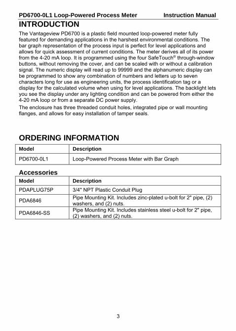
INTRODUCTION The Vantageview PD6700 is a plastic field mounted loop-powered meter fully featured for demanding applications in the harshest environmental conditions. The bar graph representation of the process input is perfect for level applications and allows for quick assessment of current conditions. The meter derives all of its power from the 4-20 mA loop. It is programmed using the four SafeTouch® through-window buttons, without removing the cover, and can be scaled with or without a calibration signal. The numeric display will read up to 99999 and the alphanumeric display can be programmed to show any combination of numbers and letters up to seven characters long for use as engineering units, the process identification tag or a display for the calculated volume when using for level applications. The backlight lets you see the display under any lighting condition and can be powered from either the 4-20 mA loop or from a separate DC power supply.
The enclosure has three threaded conduit holes, integrated pipe or wall mounting flanges, and allows for easy installation of tamper seals.
ORDERING INFORMATION Model Description
PD6700-0L1 Loop-Powered Process Meter with Bar Graph
Accessories Model Description
PDAPLUG75P 3/4" NPT Plastic Conduit Plug
PDA6846 Pipe Mounting Kit. Includes zinc-plated u-bolt for 2" pipe, (2) washers, and (2) nuts.
PDA6846-SS Pipe Mounting Kit. Includes stainless steel u-bolt for 2" pipe, (2) washers, and (2) nuts.
PD6700-0L1 Loop-Powered Process Meter Instruction Manual
4
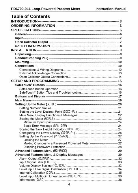
Table of Contents INTRODUCTION ---------------------------------------------------------------------- 3 ORDERING INFORMATION ------------------------------------------------------- 3 SPECIFICATIONS -------------------------------------------------------------------- 6
General ------------------------------------------------------------------------------------------- 6 Input ----------------------------------------------------------------------------------------------- 7 Open Collector Output ---------------------------------------------------------------------- 7 SAFETY INFORMATION -------------------------------------------------------------------- 8
INSTALLATION ----------------------------------------------------------------------- 9 Unpacking --------------------------------------------------------------------------------------- 9 Conduit/Stopping Plug ---------------------------------------------------------------------- 9 Mounting --------------------------------------------------------------------------------------- 10 Connections ---------------------------------------------------------------------------------- 10
Connections & Wiring Diagrams ................................................................ 12 External Acknowledge Connection ............................................................ 13 Open Collector Output Connections .......................................................... 14
SETUP AND PROGRAMMING -------------------------------------------------- 15 SafeTouch® Buttons ----------------------------------------------------------------------- 16
SafeTouch Button Operation ..................................................................... 16 SafeTouch® Button Tips and Troubleshooting ........................................... 16
Buttons and Display ----------------------------------------------------------------------- 17 Main Menu ------------------------------------------------------------------------------------- 19 Setting Up the Meter (SETUP) ------------------------------------------------------------ 20
Setting Numeric Values ............................................................................. 21 Setting the Level Decimal Point (DECIMAL) ............................................... 21 Main Menu Display Functions & Messages ............................................... 22 Scaling the Meter (SCaLe) ......................................................................... 23
Minimum Input Span ----------------------------------------------------------------- 24 Scale Error Message (SPN ERR) -------------------------------------------------- 24
Scaling the Tank Height Indicator (TANK HT) ............................................ 24 Configuring the Lower Display (DISPLAY) ................................................. 25 Setting Up the Password (PASSWRD) .......................................................... 27
Locking the Meter -------------------------------------------------------------------- 27 Making Changes to a Password Protected Meter --------------------------- 27 Disabling Password Protection --------------------------------------------------- 28
Advanced Features Menu (ADVANCE) ------------------------------------------------- 29 Advanced Features Menu & Display Messages ---------------------------------- 30
Alarm Output (OUTPUT) .............................................................................. 32 Input Signal Filter (FILTER) ....................................................................... 33 Volume Display Scaling (VOLSCAL) ............................................................ 33 Level Input Live Signal Calibration (LVL CAL) ........................................... 34 Internal Calibration (ICAL) ......................................................................... 35 Level Input Multipoint Linearization (MULTIPT) .......................................... 36 Information (INFO) ..................................................................................... 36
PD6700-0L1 Loop-Powered Process Meter Instruction Manual
5
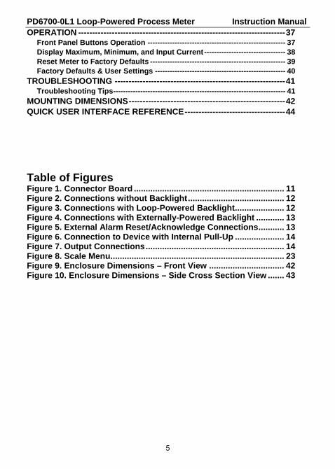
OPERATION -------------------------------------------------------------------------- 37 Front Panel Buttons Operation -------------------------------------------------------- 37 Display Maximum, Minimum, and Input Current --------------------------------- 38 Reset Meter to Factory Defaults ------------------------------------------------------- 39 Factory Defaults & User Settings ----------------------------------------------------- 40
TROUBLESHOOTING ------------------------------------------------------------- 41 Troubleshooting Tips ---------------------------------------------------------------------- 41
MOUNTING DIMENSIONS -------------------------------------------------------- 42 QUICK USER INTERFACE REFERENCE ------------------------------------ 44 Table of Figures Figure 1. Connector Board ................................................................ 11 Figure 2. Connections without Backlight ......................................... 12 Figure 3. Connections with Loop-Powered Backlight ..................... 12 Figure 4. Connections with Externally-Powered Backlight ............ 13 Figure 5. External Alarm Reset/Acknowledge Connections ........... 13 Figure 6. Connection to Device with Internal Pull-Up ..................... 14 Figure 7. Output Connections ........................................................... 14 Figure 8. Scale Menu .......................................................................... 23 Figure 9. Enclosure Dimensions – Front View ................................ 42 Figure 10. Enclosure Dimensions – Side Cross Section View ....... 43

PD6700-0L1 Loop-Powered Process Meter Instruction Manual
6
SPECIFICATIONS Except where noted all specifications apply to operation at +25°C.
General DISPLAY Five digits
(-9999 to 99999) 0.60" (15.2 mm) high, 7-segment, automatic lead zero blanking.
Seven characters 0.4" (10.2 mm) high, 14-segment. Symbols Bar Graph which displays process
input from 0-100% of scaled value. Backlight White
DISPLAY UPDATE RATE
Ambient > -25°C: 2 Updates/Second Ambient < -25°C: 1 Update/5 Seconds
DISPLAY OVERRANGE
Display flashes 99999
DISPLAY UNDERRANGE
Display flashes -9999
PROGRAMMING METHOD
Four SafeTouch® through-window buttons when cover is installed. Four internal pushbuttons when cover is removed.
NOISE FILTER Programmable LO, med, HI, or OFF RECALIBRATION Recalibration is recommended at least every 12 months. MAX/MIN DISPLAY
Max/Min readings reached by the process are stored until reset by the user or until power to the meter is turned off.
PASSWORD Programmable password restricts modification of programmed settings.
NON-VOLATILE MEMORY
All programmed settings are stored in non-volatile memory for a minimum of ten years if power is lost.
NORMAL MODE REJECTION
64 dB at 50/60 Hz
ENVIRONMENTAL Operating temperature range: -40 to 75°C Storage temperature range: -40 to 75°C Relative humidity: 0 to 90% non-condensing
CONNECTIONS Screw terminals accept 12 to 22 AWG wire ENCLOSURE
NEMA 4X, IP65 plastic field enclosure. Color: grey. Three ¾" NPT threaded conduit openings. One ¾" NPT plastic conduit plug, with 1.29" wrenching flats and a screwdriver slot, is included.
MOUNTING May be mounted directly to conduit. Two slotted flanges for wall mounting or NPS 1½" to 2½" or DN 40 to 65 mm pipe mounting. See Mounting Dimensions on page 42.
OVERALL DIMENSIONS
5.67" x 5.25" x 4.18" (W x H x D) (144 mm x 133 mm x 106 mm)
WEIGHT 1.65 lbs (26.4 oz, 0.75 kg) WARRANTY 3 years parts and labor

PD6700-0L1 Loop-Powered Process Meter Instruction Manual
7
Input
ACCURACY ±0.03% of calibrated span ±1 count, square root & programmable exponent accuracy range: 10-100% of calibrated span.
MULTI-POINT LINEARIZATION
2 to 32 points
PROGRAMMABLE EXPONENT
1.0001 to 2.9999
LOW FLOW CUTOFF 0-99999 (0 disables cutoff function)
TEMPERATURE DRIFT
50 PPM/C from -40 to 75C ambient
DECIMAL POINT User selectable decimal point
MINIMUM SPAN Input 1 & Input 2: 0.10 mA
CALIBRATION RANGE
An Error message will appear if input 1 and input 2 signals are too close together.
Input Range
Minimum Span Input 1 & Input 2
4-20 mA 0.10 mA
MAXIMUM VOLTAGE DROP
Without Backlight or with Externally-Powered (DC Powered) Backlight
With Loop-Powered Backlight
3.0 VDC @ 20 mA 6.0 VDC @ 20 mA
EQUIVALENT RESISTANCE
150 Ω @ 20 mA 300 Ω @ 20 mA
EXTERNALLY POWERED BACKLIGHT
Voltage Range: Maximum Power
9-36 VDC 9 VDC 12 VDC 24 VDC 36 VDC
0.2 W 0.25 W 0.5 W 0.75 W
INPUT OVERLOAD
Over current protection to 2 A max.
Open Collector Output
RATING Isolated open collector, 30 VDC @ 150 mA max.
ALARM OUTPUT Assign to level or volume for high or low alarm trip point.
DEADBAND 0-100% FS, user selectable
ACKNOWLEDGE Front panel ENTER button and external RESET terminals resets output and screen indication.

PD6700-0L1 Loop-Powered Process Meter Instruction Manual
8
SAFETY INFORMATION
WARNINGS
Read complete instructions prior to installation and operation of the meter.
Installation and service should be performed only by trained service personnel. Service requiring replacement of internal components must be performed at the factory.
Disconnect from supply before opening enclosure. Keep cover tight while circuits are alive.
If the meter is installed in a high voltage environment and a fault or installation error occurs, high voltage may be present on any lead.
.

PD6700-0L1 Loop-Powered Process Meter Instruction Manual
9
INSTALLATION
WARNING
Hazardous voltages may exist within enclosure. Installation and service should be performed only by trained service personnel.
Wiring connectors are accessed by opening the enclosure. To access electrical connectors, remove the 2 captive screws, then disconnect the ribbon cable from the display module and set the display module aside.
Unpacking Remove the meter from box. Inspect the packaging and contents for damage. Report damages, if any, to the carrier.
If any part is missing or the meter malfunctions, please contact your supplier or the factory for assistance.
Conduit/Stopping Plug
The PD6700-0L1 is provided with three ¾" NPT threaded conduit openings and one IP68 rated ¾" NPT plastic conduit plug.
The conduit/stopping plug included has 1.29" wrenching flats and a screwdriver slot.
PD6700-0L1 Loop-Powered Process Meter Instruction Manual
10
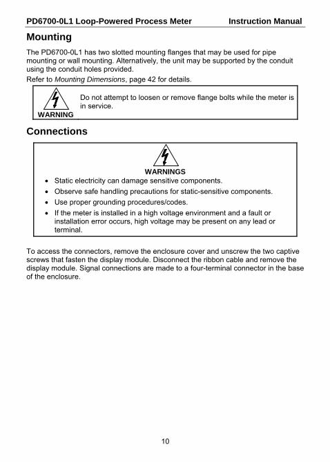
Mounting
The PD6700-0L1 has two slotted mounting flanges that may be used for pipe mounting or wall mounting. Alternatively, the unit may be supported by the conduit using the conduit holes provided.
Refer to Mounting Dimensions, page 42 for details.
WARNING
Do not attempt to loosen or remove flange bolts while the meter is in service.
Connections
WARNINGS
Static electricity can damage sensitive components.
Observe safe handling precautions for static-sensitive components.
Use proper grounding procedures/codes.
If the meter is installed in a high voltage environment and a fault or installation error occurs, high voltage may be present on any lead or terminal.
To access the connectors, remove the enclosure cover and unscrew the two captive screws that fasten the display module. Disconnect the ribbon cable and remove the display module. Signal connections are made to a four-terminal connector in the base of the enclosure.
PD6700-0L1 Loop-Powered Process Meter Instruction Manual
11
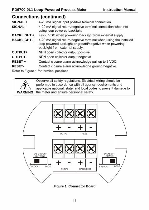
Connections (continued) SIGNAL + 4-20 mA signal input positive terminal connection
SIGNAL - 4-20 mA signal return/negative terminal connection when not using loop powered backlight.
BACKLIGHT + +9-36 VDC when powering backlight from external supply.
BACKLIGHT - 4-20 mA signal return/negative terminal when using the installed loop powered backlight or ground/negative when powering backlight from external supply.
OUTPUT+ NPN open collector output positive.
OUTPUT- NPN open collector output negative.
RESET + Contact closure alarm acknowledge pull up to 3 VDC.
RESET- Contact closure alarm acknowledge ground/negative.
Refer to Figure 1 for terminal positions.
WARNING
Observe all safety regulations. Electrical wiring should be performed in accordance with all agency requirements and applicable national, state, and local codes to prevent damage to the meter and ensure personnel safety.
Figure 1. Connector Board
SAFE-TOUCHBUTTONS
BACKLIGHTPOWER
UNLOCK LOCK LOOP9-36 VDC+ - + -
SIGNAL BACKLIGHT
+ - + -OUTPUT RESET
PD6700-0L1 Loop-Powered Process Meter Instruction Manual
12
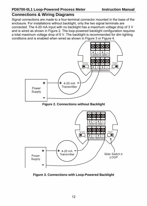
Connections & Wiring Diagrams Signal connections are made to a four-terminal connector mounted in the base of the enclosure. For installations without backlight, only the two signal terminals are connected. The 4-20 mA input with no backlight has a maximum voltage drop of 3 V and is wired as shown in Figure 2. The loop-powered backlight configuration requires a total maximum voltage drop of 6 V. The backlight is recommended for dim lighting conditions and is enabled when wired as shown in Figure 3 or Figure 4.
Figure 2. Connections without Backlight
Figure 3. Connections with Loop-Powered Backlight
4-20 mATransmitterPower
Supply
SAFE-TOUCHBUTTONS
BACKLIGHTPOWER
UNLOCK LOCK LOOP9-36 VDC+ - + -SIGNAL BACKLIGHT
+ - + -OUTPUT RESET
PD6700-0L1 Loop-Powered Process Meter Instruction Manual
13
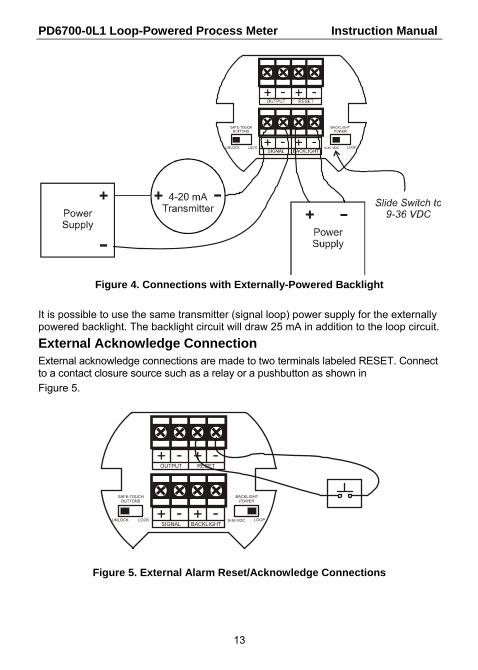
Figure 4. Connections with Externally-Powered Backlight
It is possible to use the same transmitter (signal loop) power supply for the externally powered backlight. The backlight circuit will draw 25 mA in addition to the loop circuit.
External Acknowledge Connection External acknowledge connections are made to two terminals labeled RESET. Connect to a contact closure source such as a relay or a pushbutton as shown in
Figure 5.
Figure 5. External Alarm Reset/Acknowledge Connections
SAFE-TOUCHBUTTONS
BACKLIGHTPOWER
UNLOCK LOCK LOOP9-36 VDC+ - + -SIGNAL BACKLIGHT
+ - + -OUTPUT RESET
PD6700-0L1 Loop-Powered Process Meter Instruction Manual
14
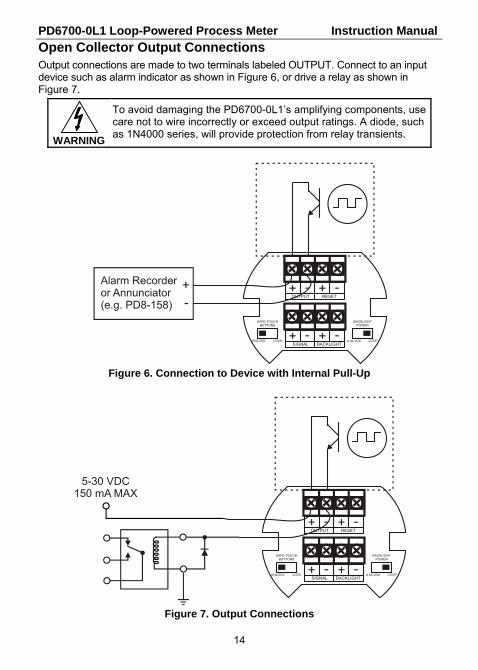
Open Collector Output Connections Output connections are made to two terminals labeled OUTPUT. Connect to an input device such as alarm indicator as shown in Figure 6, or drive a relay as shown in Figure 7.
WARNING
To avoid damaging the PD6700-0L1’s amplifying components, use care not to wire incorrectly or exceed output ratings. A diode, such as 1N4000 series, will provide protection from relay transients.
Figure 6. Connection to Device with Internal Pull-Up
Figure 7. Output Connections
SAFE-TOUCHBUTTONS
BACKLIGHTPOWER
UNLOCK LOCK LOOP9-36 VDC+ - + -SIGNAL BACKLIGHT
+ - + -OUTPUT RESET
+Alarm Recorderor Annunciator(e.g. PD8-158) -
SAFE-TOUCHBUTTONS
BACKLIGHTPOWER
UNLOCK LOCK LOOP9-36 VDC+ - + -SIGNAL BACKLIGHT
+ - + -OUTPUT RESET
5-30 VDC150 mA MAX

PD6700-0L1 Loop-Powered Process Meter Instruction Manual
15
SETUP AND PROGRAMMING
There is no need to recalibrate the meter for milliamps when first received from the factory.
The meter is factory calibrated for milliamps prior to shipment. The calibration equipment is certified to NIST standards.
Overview Setup and programming is done through the infrared through-window SafeTouch® buttons, or using the mechanical buttons when uncovered. There are two slide switches located on the connector board. One is used to select backlight power (if equipped) and the other is to lock or unlock the SafeTouch® Buttons.
After all connections have been completed and verified, connect the ribbon cable to the display module, fasten the display module to the base, install enclosure cover, and then apply power.

PD6700-0L1 Loop-Powered Process Meter Instruction Manual
16
SafeTouch® Buttons
The PD6700-0L1 is equipped with four sensors that operate as through-window buttons so that it can be programmed and operated without removing the cover (and exposing the electronics) in a hazardous area. These buttons can be disabled for security by selecting the LOCK setting on the SAFE-TOUCH BUTTONS switch located on the connector board in the base of the enclosure.
SafeTouch Button Operation To actuate a button, press and remove one finger to the window directly over the marked button area. Remove finger to at least 4 inches away from the window in between button activations. SafeTouch and mechanical buttons may be held to cycle through menus or digits in place of repeatedly pushing a button.
The sensors are disabled when a mechanical button is pressed and will automatically be re-enabled after 60 seconds of inactivity.
SafeTouch® Button Tips and Troubleshooting The SafeTouch Buttons are designed to filter normal levels of ambient interference and to protect against false triggering, however it is recommended that the SafeTouch® Buttons be turned off (slide SAFE-TOUCH BUTTONS switch to OFF) if there is an infrared interference source in line-of-sight to the display or if the buttons are not needed.
SafeTouch® Button Tips:
To the extent possible, install the display facing away from sunlight, windows, reflective objects and any sources of infrared interference.
Keep the window clean.
Tighten the cover securely.
Use a password to prevent tampering.
If the cover has not been installed and secured tightly, it may take a moment for the SafeTouch buttons to properly self-calibrate when the cover is tight-ened.
IMPORTANT
SafeTouch buttons will not work if two or more buttons are detected as being pressed simultaneously. As a result, be careful to avoid triggering multiple buttons or reaching across one button location to press another.

PD6700-0L1 Loop-Powered Process Meter Instruction Manual
17
Buttons and Display
Button Symbol
Description Symbol Status
Menu
Tank Level Indicator
Right arrow/Reset
Up arrow/Display
Enter
MENU
RESET
ENTER
DISPLAY
PD6700-0L1 Loop-Powered Process Meter Instruction Manual
18
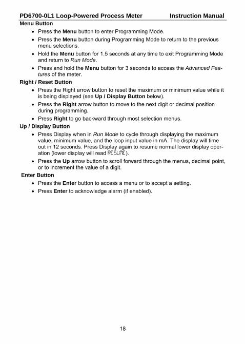
Menu Button
Press the Menu button to enter Programming Mode.
Press the Menu button during Programming Mode to return to the previous menu selections.
Hold the Menu button for 1.5 seconds at any time to exit Programming Mode and return to Run Mode.
Press and hold the Menu button for 3 seconds to access the Advanced Fea-tures of the meter.
Right / Reset Button
Press the Right arrow button to reset the maximum or minimum value while it is being displayed (see Up / Display Button below).
Press the Right arrow button to move to the next digit or decimal position during programming.
Press Right to go backward through most selection menus.
Up / Display Button
Press Display when in Run Mode to cycle through displaying the maximum value, minimum value, and the loop input value in mA. The display will time out in 12 seconds. Press Display again to resume normal lower display oper-ation (lower display will read RESUME).
Press the Up arrow button to scroll forward through the menus, decimal point, or to increment the value of a digit.
Enter Button
Press the Enter button to access a menu or to accept a setting.
Press Enter to acknowledge alarm (if enabled).
PD6700-0L1 Loop-Powered Process Meter Instruction Manual
19
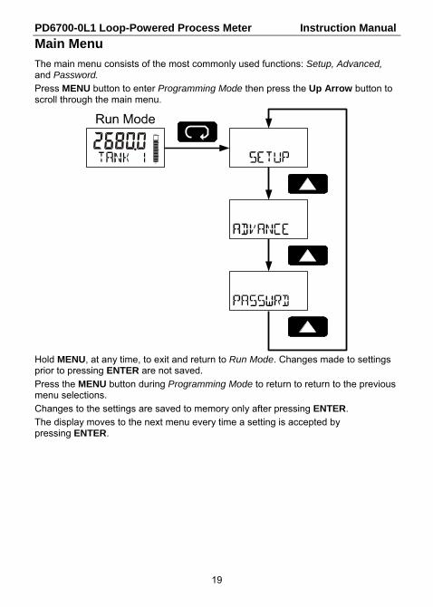
Main Menu
The main menu consists of the most commonly used functions: Setup, Advanced, and Password.
Press MENU button to enter Programming Mode then press the Up Arrow button to scroll through the main menu.
Hold MENU, at any time, to exit and return to Run Mode. Changes made to settings prior to pressing ENTER are not saved.
Press the MENU button during Programming Mode to return to return to the previous menu selections.
Changes to the settings are saved to memory only after pressing ENTER.
The display moves to the next menu every time a setting is accepted by pressing ENTER.

PD6700-0L1 Loop-Powered Process Meter Instruction Manual
20
Setting Up the Meter (SETUP)
The Setup menu is used to select:
1. Engineering units decimal location
2. Engineering units display scale
3. Tank indicator full and empty values
4. Bottom display selection
Press the ENTER button to access any menu or press UP arrow button to scroll through choices.
Hold MENU, at any time, to exit and return to Run Mode. Changes made to settings prior to pressing ENTER are not saved.
Press the MENU button during Programming Mode to return to return to the previous menu selections.
SETuP
SETuP
SETuP
SETuP

PD6700-0L1 Loop-Powered Process Meter Instruction Manual
21
Setting Numeric Values The numeric values are set using the RIGHT and UP arrow buttons. Press RIGHT arrow to select next digit and UP arrow to increment digit.
The digit being changed blinks.
Press the ENTER button, at any time, to accept a setting.
Hold MENU, at any time, to exit and return to Run Mode. Changes made to settings prior to pressing ENTER are not saved.
Press the MENU button during Programming Mode to return to return to the previous menu selections.
Setting the Level Decimal Point (DECIMAL) Decimal point may be set with up to four decimal places or with no decimal point.
Pressing the Right arrow moves the decimal point one place to the right and pressing the Up arrow moves the decimal point one place to the left.
Note: The currently selected digit will blink. Pressing theRight Arrow button will select the next digit, causing it to blink.
SETuP 1111.1 222.22
PD6700-0L1 Loop-Powered Process Meter Instruction Manual
22
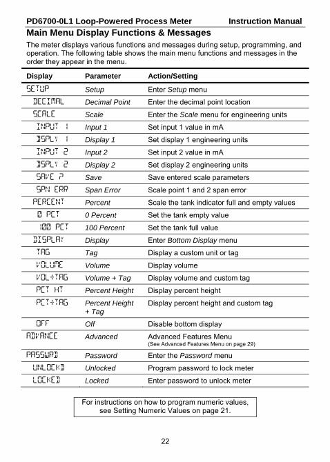
Main Menu Display Functions & Messages The meter displays various functions and messages during setup, programming, and operation. The following table shows the main menu functions and messages in the order they appear in the menu.
Display Parameter Action/Setting
SETUP Setup Enter Setup menu
DECIMAL Decimal Point Enter the decimal point location
SCALE Scale Enter the Scale menu for engineering units
INPUT 1 Input 1 Set input 1 value in mA
DSPLY 1 Display 1 Set display 1 engineering units
INPUT 2 Input 2 Set input 2 value in mA
DSPLY 2 Display 2 Set display 2 engineering units
SAVE ? Save Save entered scale parameters
SPN ERR Span Error Scale point 1 and 2 span error
PERCENT Percent Scale the tank indicator full and empty values
0 PCT 0 Percent Set the tank empty value
100 PCT 100 Percent Set the tank full value
DISPLAY Display Enter Bottom Display menu
TAG Tag Display a custom unit or tag
VOLUME Volume Display volume
VOL+TAG Volume + Tag Display volume and custom tag
PCT HT Percent Height Display percent height
PCT+TAG Percent Height + Tag
Display percent height and custom tag
OFF Off Disable bottom display
ADVANCE Advanced Advanced Features Menu (See Advanced Features Menu on page 29)
PASSWRD Password Enter the Password menu
UNLOCKD Unlocked Program password to lock meter
LOCKED Locked Enter password to unlock meter
For instructions on how to program numeric values, see Setting Numeric Values on page 21.

PD6700-0L1 Loop-Powered Process Meter Instruction Manual
23
Scaling the Meter (SCaLe) The 4-20 mA input can be scaled to display the process in engineering units. To scale the meter, enter the value in milliamps (mA) for input 1, and then the corresponding engineering units display value. Do the same for input 2.
After entering the display 2 value, confirm the new scale by pressing ENTER at the Save menu.
A signal source is not needed to scale the meter; simply program the inputs and corresponding display values.
Figure 8. Scale Menu
For instructions on using multipoint scaling, see Level Input Multipoint Linearization (MULTIPT) on page 36.
For instructions on how to program numeric values see Setting Numeric Values, page 21.
PD6700-0L1 Loop-Powered Process Meter Instruction Manual
24
Minimum Input Span The minimum input span is the minimum difference between input 1 and input 2 signals required to complete the calibration or scaling of the meter. The minimum span is 0.10 mA.
Scale Error Message (SPN ERR) If the minimum span is not maintained, the meter will show a span error (SPN ERR) and revert to input 2, allowing the appropriate input signals to be applied.
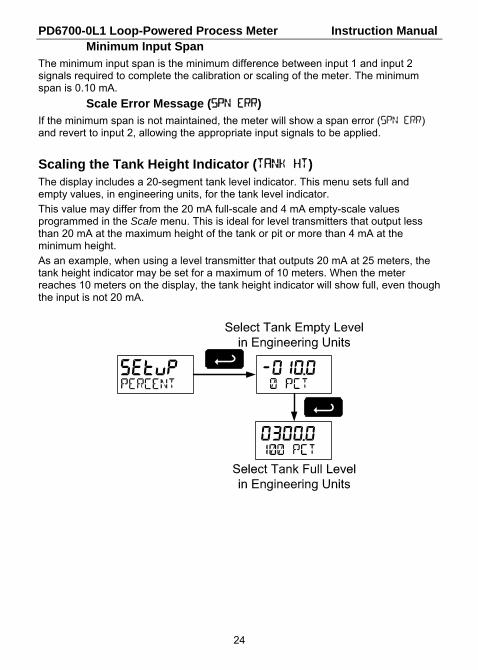
Scaling the Tank Height Indicator (TANK HT) The display includes a 20-segment tank level indicator. This menu sets full and empty values, in engineering units, for the tank level indicator.
This value may differ from the 20 mA full-scale and 4 mA empty-scale values programmed in the Scale menu. This is ideal for level transmitters that output less than 20 mA at the maximum height of the tank or pit or more than 4 mA at the minimum height.
As an example, when using a level transmitter that outputs 20 mA at 25 meters, the tank height indicator may be set for a maximum of 10 meters. When the meter reaches 10 meters on the display, the tank height indicator will show full, even though the input is not 20 mA.
setup -010.0
0300.0
PD6700-0L1 Loop-Powered Process Meter Instruction Manual
25
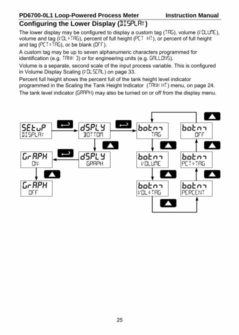
Configuring the Lower Display (DISPLAY) The lower display may be configured to display a custom tag (TAG), volume (VOLUME), volume and tag (VOL+TAG), percent of full height (PCT HT), or percent of full height and tag (PCT+TAG), or be blank (OFF).
A custom tag may be up to seven alphanumeric characters programmed for identification (e.g. TANK 3) or for engineering units (e.g. GALLONS).
Volume is a separate, second scale of the input process variable. This is configured in Volume Display Scaling (VOLSCAL) on page 33.
Percent full height shows the percent full of the tank height level indicator programmed in the Scaling the Tank Height Indicator (TANK HT) menu, on page 24.
The tank level indicator (GRAPH) may also be turned on or off from the display menu.
setup dsply
dsplygrapH
grapH
botnm
botnm
botnm
botnm
botnm
botnm

PD6700-0L1 Loop-Powered Process Meter Instruction Manual
26
Setting the TAG (TAG)
Any bottom display setting that includes a tag will require the tag to be entered.
The fully alphanumeric values for the tag are set using the RIGHT button to select the digit, the UP and RIGHT arrow buttons to select the digit reading, and the ENTER button to confirm and select the next digit.
dsply botnm
botnm
botnm
PD6700-0L1 Loop-Powered Process Meter Instruction Manual
27
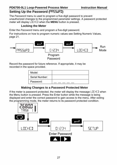
Setting Up the Password (PASSWRD) The Password menu is used to program a five-digit password to prevent unauthorized changes to the programmed parameter settings. A password protected meter will display LOCKED when the MENU button is pressed.
Locking the Meter Enter the Password menu and program a five-digit password.
For instructions on how to program numeric values see Setting Numeric Values, page 21.
Record the password for future reference. If appropriate, it may be recorded in the space provided.
Model:
Serial Number:
Password: __ __ __ __ __
Making Changes to a Password Protected Meter If the meter is password protected, the meter will display the message LOCKED when the Menu button is pressed. Press the Enter button while the message is being displayed and enter the correct password to gain access to the menu. After exiting the programming mode, the meter returns to its password protected condition.
PD6700-0L1 Loop-Powered Process Meter Instruction Manual
28
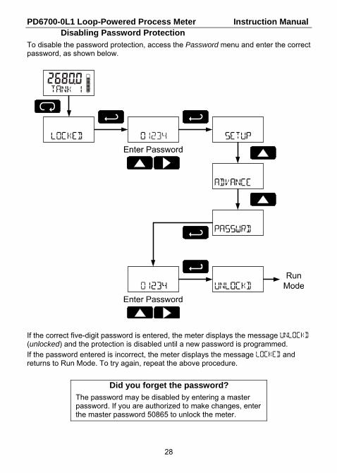
Disabling Password Protection To disable the password protection, access the Password menu and enter the correct password, as shown below.
If the correct five-digit password is entered, the meter displays the message UNLOCKD (unlocked) and the protection is disabled until a new password is programmed.
If the password entered is incorrect, the meter displays the message LOCKED and returns to Run Mode. To try again, repeat the above procedure.
Did you forget the password? The password may be disabled by entering a master password. If you are authorized to make changes, enter the master password 50865 to unlock the meter.
PD6700-0L1 Loop-Powered Process Meter Instruction Manual
29
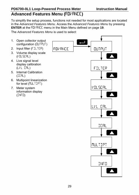
Advanced Features Menu (ADVANCE)
To simplify the setup process, functions not needed for most applications are located in the Advanced Features Menu. Access the Advanced Features Menu by pressing ENTER at the ADVANCE menu in the Main Menu defined on page 19.
The Advanced Features Menu is used to select:
1. Open collector output configuration (OUTPUT)
2. Input filter (FILTER)
3. Volume display scale (VOLSCAL)
4. Live signal level display calibration (LVL CAL)
5. Internal Calibration (ICAL)
6. Multipoint linearization for level (MULTIPT)
7. Meter system information display (INFO)
PD6700-0L1 Loop-Powered Process Meter Instruction Manual
30
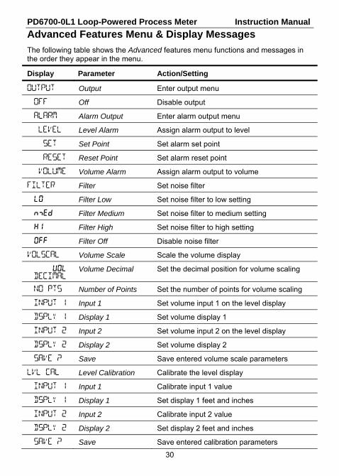
Advanced Features Menu & Display Messages
The following table shows the Advanced features menu functions and messages in the order they appear in the menu.
Display Parameter Action/Setting
OUTPUT Output Enter output menu
OFF Off Disable output
ALARM Alarm Output Enter alarm output menu
LEVEL Level Alarm Assign alarm output to level
SET Set Point Set alarm set point
RESET Reset Point Set alarm reset point
VOLUME Volume Alarm Assign alarm output to volume
FILTER Filter Set noise filter
LO Filter Low Set noise filter to low setting
nmED Filter Medium Set noise filter to medium setting
HI Filter High Set noise filter to high setting
OFF Filter Off Disable noise filter
VOLSCAL Volume Scale Scale the volume display
vOl DECIMAL
Volume Decimal Set the decimal position for volume scaling
NO PTS Number of Points Set the number of points for volume scaling
INPUT 1 Input 1 Set volume input 1 on the level display
DSPLY 1 Display 1 Set volume display 1
INPUT 2 Input 2 Set volume input 2 on the level display
DSPLY 2 Display 2 Set volume display 2
SAVE ? Save Save entered volume scale parameters
LVL CAL Level Calibration Calibrate the level display
INPUT 1 Input 1 Calibrate input 1 value
DSPLY 1 Display 1 Set display 1 feet and inches
INPUT 2 Input 2 Calibrate input 2 value
DSPLY 2 Display 2 Set display 2 feet and inches
SAVE ? Save Save entered calibration parameters
PD6700-0L1 Loop-Powered Process Meter Instruction Manual
31
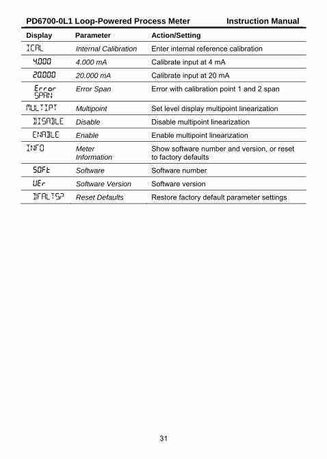
Display Parameter Action/Setting
ICAL Internal Calibration Enter internal reference calibration
4.000 4.000 mA Calibrate input at 4 mA
20.000 20.000 mA Calibrate input at 20 mA
Error SPAN
Error Span Error with calibration point 1 and 2 span
MULTIPT Multipoint Set level display multipoint linearization
DISABLE Disable Disable multipoint linearization
ENABLE Enable Enable multipoint linearization
INFO Meter Information
Show software number and version, or reset to factory defaults
SOFT Software Software number
ver Software Version Software version
DFALTS? Reset Defaults Restore factory default parameter settings

PD6700-0L1 Loop-Powered Process Meter Instruction Manual
32
Alarm Output (OUTPUT) The PD6700-0L1 is equipped with an NPN open collector output that may be set up for high or low alarm trip point based on the level display (LEVEL) or the volume scale (VOLUME). The output may be disabled by selecting OFF.
When the alarm is enabled for level and the alarm set point has been reached, the level display will flash, accompanied by the bottom display alternating between normal display and HI ALRM or LO ALRM, depending on whether a high alarm or a low alarm has been set. A tank height indicator segment will flash at the level to which the alarm is set while the level indicator is at or above the alarm point.
When the alarm is enabled for volume and the alarm set point has been reached, the bottom display will flash, alternating between its normal display and HI ALRM or LO ALRM, depending on whether a high alarm or a low alarm has been set.
To set a high alarm, program the set point above the reset point.
To set a low alarm, program the set point below the reset point.
To acknowledge an alarm, press the ENTER button once for acknowledge prompt and a second time to confirm. Acknowledging an alarm will turn off the alarm output and stop the display from flashing. The HI or LO symbol will remain until the alarm condition is cleared.
The alarm status will show on the display even if the output is not wired.

PD6700-0L1 Loop-Powered Process Meter Instruction Manual
33
Input Signal Filter (FILTER) The noise filter is available for unusually noisy signals that cause an unstable process variable display. The noise filter averages the input signal over a certain period. The filter level can be set to low (LO), medium (MED), high (HI), or off (OFF). The higher the filter setting, the longer the averaging time and so the longer the display may take to find its final value.
The filter contains a noise filter bypass feature so that while small variations in the signal will be filtered out, large, abrupt changes to the input signal are displayed immediately.
Volume Display Scaling (VOLSCAL) Volume may be scaled as a function of the level display. It may use up to 32-point linearization. The multi-point linearization can be used to linearize the display for non-linear signals such as those from level transmitters used to measure volume in odd-shaped tanks.
To display the volume, select a bottom display including the volume display in the Display menu as shown in Configuring the Lower Display (DISPLAY) on page 25.
To scale the volume display, select the decimal point location (0, 1, 2, 3, or 4), then enter the level in engineering units for input 1, the corresponding volume display value, and the same for input 2.
After entering the display 2 value, confirm the new volume scale by pressing ENTER at the Save menu.
FT IN
PD6700-0L1 Loop-Powered Process Meter Instruction Manual
34
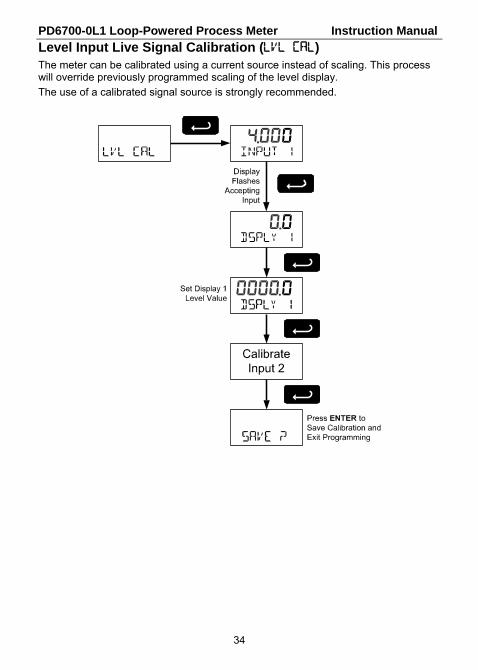
Level Input Live Signal Calibration (LVL CAL) The meter can be calibrated using a current source instead of scaling. This process will override previously programmed scaling of the level display.
The use of a calibrated signal source is strongly recommended.

PD6700-0L1 Loop-Powered Process Meter Instruction Manual
35
Internal Calibration (ICAL)
There is no need to recalibrate the meter when first received from the factory. The meter is factory calibrated prior to shipment. The calibration equipment is certified to NIST standards
The internal calibration is the meter’s master calibration that makes scaling the meter without a signal source possible. Use of a calibrated signal source is necessary to perform an internal calibration of the meter. Check calibration of the meter at least every 12 months. Incorrect calibration will affect the ability of the meter to properly read, scale, and display the input.
Notes:
The signal source must have a full-scale accuracy of 0.002% or better between 4 and 20 mA in order to maintain the specified accuracy of the meter.
Allow the meter to warm up for at least 15 minutes before performing the calibration procedure.
Press MENU, navigate to ADVANCE and press enter to access the Advanced Features Menu. Press the UP arrow button to scroll to the Internal Calibration menu (ICAL) and press ENTER.
The meter displays 4.000. Apply a 4.000 mA signal and press ENTER. The display flashes for a moment while the meter is accepting the signal.
After the signal is accepted, the meter displays 20.000. Apply a 20.000 mA signal and press ENTER. The display flashes for a moment while the meter is accepting the signal.
Calibration Error Message (Error SPAN)
An error message indicates that the calibration process was not successful. After the error message is displayed, the meter will revert to the 4.000 calibration menu. The error message might be caused by inadvertently leaving the signal at the previous level or not maintaining the minimum span. Press the MENU button to cancel the current calibration process if necessary.
PD6700-0L1 Loop-Powered Process Meter Instruction Manual
36
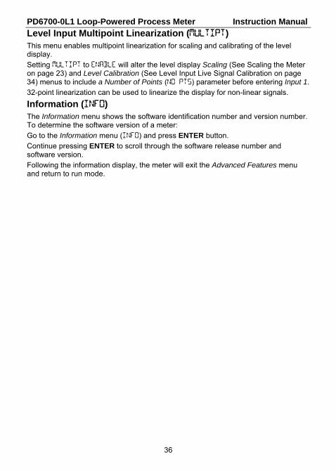
Level Input Multipoint Linearization (MULTIPT) This menu enables multipoint linearization for scaling and calibrating of the level display.
Setting MULTIPT to ENABLE will alter the level display Scaling (See Scaling the Meter on page 23) and Level Calibration (See Level Input Live Signal Calibration on page 34) menus to include a Number of Points (NO PTS) parameter before entering Input 1.
32-point linearization can be used to linearize the display for non-linear signals.
Information (INFO) The Information menu shows the software identification number and version number. To determine the software version of a meter:
Go to the Information menu (INFO) and press ENTER button.
Continue pressing ENTER to scroll through the software release number and software version.
Following the information display, the meter will exit the Advanced Features menu and return to run mode.
PD6700-0L1 Loop-Powered Process Meter Instruction Manual
37
OPERATION
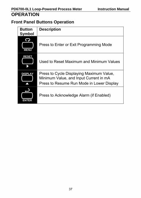
Front Panel Buttons Operation
Button Symbol
Description
Press to Enter or Exit Programming Mode
Used to Reset Maximum and Minimum Values
Press to Cycle Displaying Maximum Value, Minimum Value, and Input Current in mA Press to Resume Run Mode in Lower Display
Press to Acknowledge Alarm (if Enabled)
MENU
RESET
ENTER
DISPLAY

PD6700-0L1 Loop-Powered Process Meter Instruction Manual
38
Display Maximum, Minimum, and Input Current
The maximum and minimum values and the measured input loop current may be displayed temporarily on the lower display. To display these values, press the DISPLAY button. The meter will display the word MAXIMUM on the bottom display and the maximum value reached (since the last maximum reset) on the top display. Press the DISPLAY button again and the meter will display the word MINIMUM on the bottom display and the minimum value reached on the top display. Pressing the RESET button while either of these values is displayed will reset that value to the current display value.
Press the DISPLAY button a third time and the meter will display LOOP MA on the bottom display and the measured input current in milliamps (mA) on the top display. The current display will remain for 10 seconds and then the lower display will return to normal run mode as programmed in Configuring the Lower Display (DISPLAY) on page 25. Press the DISPLAY button a fourth time to return to the normal operation. The meter will display RESUME followed by the run mode lower display.
PD6700-0L1 Loop-Powered Process Meter Instruction Manual
39
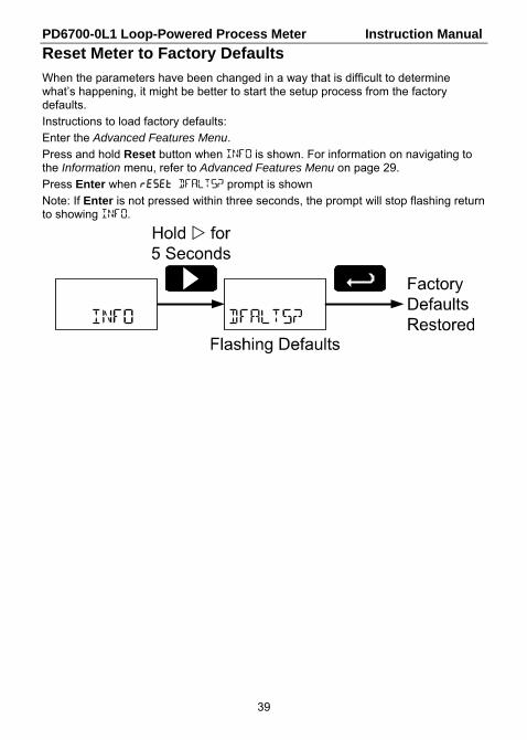
Reset Meter to Factory Defaults
When the parameters have been changed in a way that is difficult to determine what’s happening, it might be better to start the setup process from the factory defaults.
Instructions to load factory defaults:
Enter the Advanced Features Menu.
Press and hold Reset button when INFO is shown. For information on navigating to the Information menu, refer to Advanced Features Menu on page 29.
Press Enter when RESET DFALTS? prompt is shown
Note: If Enter is not pressed within three seconds, the prompt will stop flashing return to showing INFO.

PD6700-0L1 Loop-Powered Process Meter Instruction Manual
40
Factory Defaults & User Settings
The following table shows the factory setting for most of the programmable parameters on the meter. Next to the factory setting, the user may record the new setting for the particular application.
Model: ______________ S/N: _______________ Date: _________
Parameter Display Default Setting User Setting
Basic Setup
Level Decimal Point DECIMAL 1111.1
Input 1 INPUT 1 4.000 mA
Display 1 DSPLY 1 0.0
Input 2 INPUT 2 20.00 mA
Display 2 DSPLY 2 100.0
Tank Indicator 0% 0 pCT 0.0
Tank Indicator 100 % 100 PCT 100.0
Bottom Display BOTTOM Tag
Bar Graph GRAPH On
Tag TAG TANK 1
Advanced Features
Output OUTPUT Off
Filter FILTER Low
Volume Decimal Point vOl
DECIMAL 0000000
Volume Scale Number of Points NO PTS 02
Volume Scale Input 1 INPUT 1 0.0
Volume Display 1 DSPLY 1 0
Volume Scale Input 2 INPUT 2 100.0
Volume Display 2 DSPLY 2 100,000
Multipoint MULTIPT Disable
Password
Password PASSWRD 00000 (unlocked)
PD6700-0L1 Loop-Powered Process Meter Instruction Manual
41
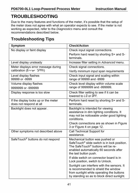
TROUBLESHOOTING Due to the many features and functions of the meter, it’s possible that the setup of the meter does not agree with what an operator expects to see. If the meter is not working as expected, refer to the Diagnostics menu and consult the recommendations described below.
Troubleshooting Tips
Symptom Check/Action
No display or faint display Check input signal connections.
Perform hard reset by shorting S+ and S- terminals.
Level display unsteady Increase filter setting in Advanced menu.
Meter displays error message during calibration (error SPAN)
Check signal connections.
Verify minimum input span requirements
Level display flashes 99999 or -9999
Check input signal and scaling within range of 99999 and -9999
Volume display flashes
9999999 or -999999
Check level display within volume scale range of 9999999 and -999999.
Display response is too slow Check filter setting to see if it can be lowered to LO or OFF.
If the display locks up or the meter does not respond at all
Perform hard reset by shorting S+ and S- terminals.
Backlight does not appear. Backlight is intended for viewing assistance in dim lighting conditions. It may not be noticeable under good lighting conditions.
Check connections are as shown in Figure 3 or Figure 4 on page 12.
Other symptoms not described above Call Technical Support for assistance.
SafeTouch® buttons do not respond Mechanical button was pushed or SafeTouch® slide switch is in lock position. The SafeTouch® buttons will be re-enabled automatically 60 seconds after the last button push.
If slide switch on connector board is in Lock position, switch to Unlock.
Sunlight can interfere with the sensors. It is recommended to shield the window from sunlight while operating the buttons by standing so as to block direct sunlight.

PD6700-0L1 Loop-Powered Process Meter Instruction Manual
42
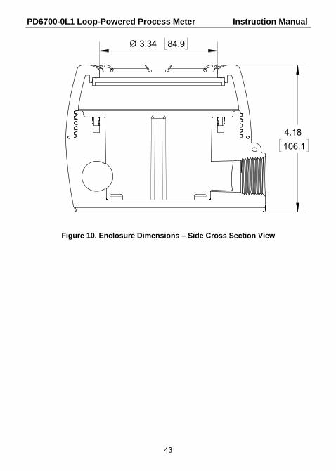
MOUNTING DIMENSIONS All units: inches [mm]
Figure 9. Enclosure Dimensions – Front View
85.1
57.2
144.0
5.25 133.3
5.67
3.35
2.250.33 8.3
PD6700-0L1 Loop-Powered Process Meter Instruction Manual
43
Figure 10. Enclosure Dimensions – Side Cross Section View
106.1
4.18
Ø 3.34 84.9

PD6700-0L1 Loop-Powered Process Meter Instruction Manual
44
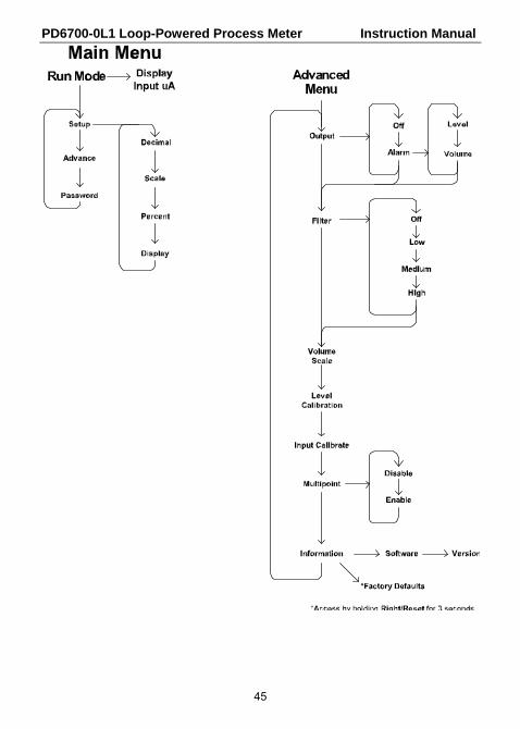
QUICK USER INTERFACE REFERENCE
Setup
Run mA DisplayAdvanced Features
UP Arrow
MENUMENU
MENU UP Arrow
Operational Modes
Hold MENUfor 5 seconds
Pushbutton Function MENU Go to programming mode or leave programming. Hold for 5
seconds to enter Advanced Features Menu directly. RIGHT Arrow Move to next digit. Go to previous menu or alphanumeric char-
acter selection. Reset max or min while displayed. UP Arrow Move to next selection or increment digit. Cycle through maxi-
mum, minimum, and mA display mode. ENTER Accept selection/value and move to next selection.
Acknowledge alarms.
PD6700-0L1 Loop-Powered Process Meter Instruction Manual
45

PD6700-0L1 Loop-Powered Process Meter Instruction Manual
46
This Page Intentionally Left Blank

PD6700-0L1 Loop-Powered Process Meter Instruction Manual
47
NOTES

PD6700-0L1 Loop-Powered Process Meter Instruction Manual
LIM6700L_B SFT087 Ver 1.300 & up
04/15
How to Contact Precision Digital
For Technical Support:
Call: (800) 610-5239 or (508) 655-7300
Fax: (508) 655-8990
Email: [email protected]
For Sales Support:
Call: (800) 343-1001 or (508) 655-7300
Fax: (508) 655-8990
Email: [email protected]
For the latest version of this manual please visit:
www.predig.com