programmable logic controllers plc’s التحكم المنطقى المبرمج
TRANSCRIPT

PProgrammable rogrammable LLogic ogic CControllersontrollers
PLC’sPLC’s
المنطقى التحكمالمبرمج

OverviewOverview
Course Contents Course Contents
What is a PLC ?What is a PLC ?
HistoryHistory
Overview of TechnologyOverview of Technology
PLC Configuration and SelectionPLC Configuration and Selection
Programming PLC’sProgramming PLC’s

Introductions to PLCIntroductions to PLC
PLC HardwarePLC Hardware
Input / Output Input / Output
ProcessingProcessing
Input DevicesInput Devices
Output DevicesOutput Devices
Course ContentsCourse Contents
Programming
Internal
Relays
Timers
Counters
Projects

What is a PLC ?What is a PLC ?

What is a PLC ?What is a PLC ?A PLC works by looking at its inputs and depending on A PLC works by looking at its inputs and depending on
their state, and the user entered program, turns on/off their state, and the user entered program, turns on/off
outputs.outputs.
A PLC can be thought of as: A PLC can be thought of as:
Industrial ComputersIndustrial Computers with specially designed architecture with specially designed architecture
in both their central units (the PLC itself) and their in both their central units (the PLC itself) and their
interfacing circuitry to field devices (input / output interfacing circuitry to field devices (input / output
connections to the real world).connections to the real world).

CommercialCommercial AndAnd Industrial Industrial ComputersComputers
Commercial Computer
Industrial Computer

History 1/5History 1/5
Early control systems consisted of Early control systems consisted of
huge control boards consisting of huge control boards consisting of
hundreds to thousands of hundreds to thousands of
electromechanical relays.electromechanical relays.
An Engineer would design the An Engineer would design the
system logic.system logic.
Electricians would receive a Electricians would receive a
schematic outline of logic then schematic outline of logic then
implement the logic with relays.implement the logic with relays.
|/|
CR3
CR3 M1
PB1 LS1 SOL2
PB2LS1
LS3
LS4

History 2/5History 2/5
The schematic was commonly called “Ladder Schematic”The schematic was commonly called “Ladder Schematic”
The Ladder displayed all switches, sensors, motors, The Ladder displayed all switches, sensors, motors,
valves, relays etc in the system.valves, relays etc in the system.
Problems: Long implementation time, Mechanical Problems: Long implementation time, Mechanical
dependence, Any system logic design change required dependence, Any system logic design change required
the power to the control board to be isolated stopping the power to the control board to be isolated stopping
productionproduction

History 3/5History 3/5
General Motors was among the first to recognize a need to General Motors was among the first to recognize a need to
replace the systems “wired control board”replace the systems “wired control board”
Hydromantic Division of GM specified the design criteria for Hydromantic Division of GM specified the design criteria for
the programmable controller in 1968.the programmable controller in 1968.
Goal – Goal – Eliminate the high cost associated with inflexible, Eliminate the high cost associated with inflexible,
Relay controlled systems.Relay controlled systems.

History 4/5History 4/5New Controller Specifications:New Controller Specifications:
– Solid State SystemSolid State System
– Computer FlexibilityComputer Flexibility
– Operate in Industrial Environment (vibrations, heat, Operate in Industrial Environment (vibrations, heat,
dust etc.) dust etc.)
– Capability of being reprogrammedCapability of being reprogrammed
– Easily programmed and maintained by electricians Easily programmed and maintained by electricians
and technicians.and technicians.
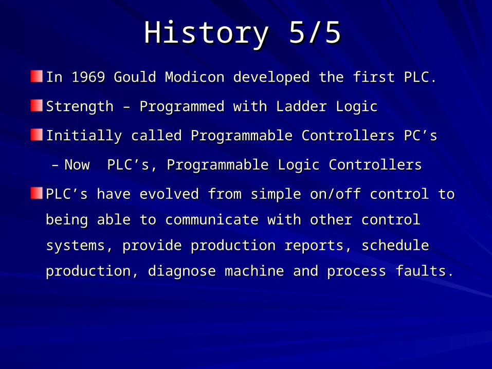
History 5/5History 5/5
In 1969 Gould Modicon developed the first PLC. In 1969 Gould Modicon developed the first PLC.
Strength – Programmed with Ladder LogicStrength – Programmed with Ladder Logic
Initially called Programmable Controllers PC’s Initially called Programmable Controllers PC’s
– Now PLC’s, Programmable Logic ControllersNow PLC’s, Programmable Logic Controllers
PLC’s have evolved from simple on/off control to being PLC’s have evolved from simple on/off control to being
able to communicate with other control systems, provide able to communicate with other control systems, provide
production reports, schedule production, diagnose production reports, schedule production, diagnose
machine and process faults.machine and process faults.

Relay Logic vs. PLC & Ladder Relay Logic vs. PLC & Ladder LogicLogic
|/|
CR3
CR3 M1
PB1 LS1 SOL2
PB2LS1
LS3
LS4
ProgrammableLogic
Controller
Inputs Outputs
CR
X4
X0 X1 Y0
Y1
| | | | ( )
X3X2 M0
| | | | ( )
| |
|/|M0
( )| |X5

PLC ConfigurationPLC Configuration
RACK
SHOE BOX (UNITARY) MICRO

The Configuration of PLCThe Configuration of PLCThe configuration of PLC refers to the packaging of the The configuration of PLC refers to the packaging of the
components.components.
Typical configurations are listed below from largest to smallest.Typical configurations are listed below from largest to smallest.
– Rack TypeRack Type : : A rack is often large (up to 18” by 30” by 10”) and
these use a range of modules that use together to build up a
system.
– ShoeboxShoebox: A compact, all-in-one unit that has limited expansion : A compact, all-in-one unit that has limited expansion
capabilities. Lower cost and compactness make these ideal for capabilities. Lower cost and compactness make these ideal for
small applications.small applications.
– MicroMicro: These units can be as small as a deck of cards. They : These units can be as small as a deck of cards. They
tend to have fixed quantities of I/O and limited abilities, but costs tend to have fixed quantities of I/O and limited abilities, but costs
will be lowest. will be lowest.
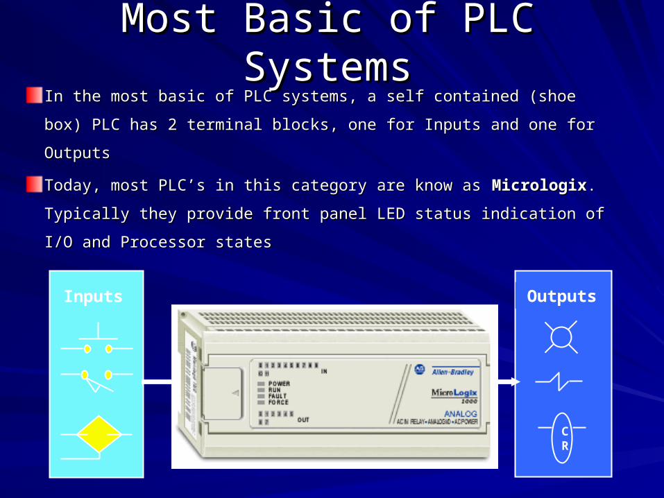
Most Basic of PLC SystemsMost Basic of PLC SystemsIn the most basic of PLC systems, a self contained (shoe box) In the most basic of PLC systems, a self contained (shoe box)
PLC has 2 terminal blocks, one for Inputs and one for OutputsPLC has 2 terminal blocks, one for Inputs and one for Outputs
Today, most PLC’s in this category are know as Today, most PLC’s in this category are know as MicrologixMicrologix. .
Typically they provide front panel LED status indication of I/O and Typically they provide front panel LED status indication of I/O and
Processor statesProcessor states
Programmable Controller
Inputs Outputs
CR

Modular Chassis Based PLC’sModular Chassis Based PLC’s
The vast majority of PLC’s installed today are modular chassis The vast majority of PLC’s installed today are modular chassis
based systems consisting of:based systems consisting of:
1.1. Processor Module (CPU)Processor Module (CPU)
2.2. Input & Output ModulesInput & Output Modules
3.3. ChassisChassis
4.4. Power SupplyPower Supply

Modular Chassis Based PLC’sModular Chassis Based PLC’s

Sizing of PLCSizing of PLC
Micro PLCs: I/O up to 32 pointsMicro PLCs: I/O up to 32 points
Small PLC: I/O up to 128 pointsSmall PLC: I/O up to 128 points
Medium PLC: I/O up to 1024 pointsMedium PLC: I/O up to 1024 points
Large PLC: I/O up to 4096 pointsLarge PLC: I/O up to 4096 points
Very Large: I/O up to 8192 pointsVery Large: I/O up to 8192 points

Overview of TechnologyOverview of Technology

Basic PLC SchemaBasic PLC Schema
CPUCPU
Power SupplyPower Supply
MemoryMemory
Input Module Input Module
Output Module Output Module
Programming devicesProgramming devices
CommunicationsCommunications
Expansion ConnectionsExpansion Connections

CPU ModuleCPU Module

CPU Module CPU Module Cont’dCont’d
The Central Processing Unit (CPU) Module is the brain of the The Central Processing Unit (CPU) Module is the brain of the
PLC.PLC.
CPU architecture may differ from one manufacturer to another, CPU architecture may differ from one manufacturer to another,
but in general, most CPUs follow this typical three-component but in general, most CPUs follow this typical three-component
organization (Processor, Memory, Power Supply) organization (Processor, Memory, Power Supply)
The term CPU is often used interchangeably with the word The term CPU is often used interchangeably with the word
ProcessorProcessor; however, the CPU encompasses all of the necessary ; however, the CPU encompasses all of the necessary
elements that form the intelligence of the system—the processor elements that form the intelligence of the system—the processor
plus the memory system and power supplyplus the memory system and power supply

PLC Operating CyclePLC Operating Cycle
SelfCheck
ExecuteCode
ScanInputs
UpdateOutputs
PLC ProgramSCAN
The basic function of a The basic function of a
programmable controller is to programmable controller is to
read all of the field input devices read all of the field input devices
and then execute the control and then execute the control
program, which according to the program, which according to the
logic programmed, will turn the logic programmed, will turn the
field output devices ON or OFF.field output devices ON or OFF.
A PLC works by continually A PLC works by continually
scanning a programscanning a program
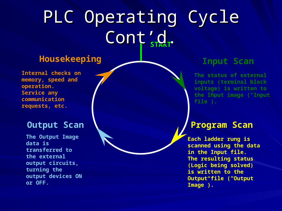
Input Scan
Program ScanOutput Scan
Housekeeping
START
Each ladder rung is scanned using the data in the Input file. The resulting status (Logic being solved) is written to the Output file (“Output Image”).
The status of external inputs (terminal block voltage) is written to the Input image (“Input file”).
The Output Image data is transferred to the external output circuits, turning the output devices ON or OFF.
Internal checks on memory, speed and operation. Service any communication requests, etc.
PLC Operating Cycle Cont’d.PLC Operating Cycle Cont’d.
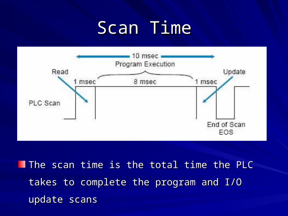
Scan TimeScan Time
The scan time is the total time the PLC takes to complete The scan time is the total time the PLC takes to complete
the program and I/O update scansthe program and I/O update scans

Scan Time Cont’d Scan Time Cont’d
The program scan time generally depends on two The program scan time generally depends on two
factors:factors:
– the amount of memory taken by the control programthe amount of memory taken by the control program
– the type of instructions used in the program (which the type of instructions used in the program (which
affects the time needed to execute the instructions)affects the time needed to execute the instructions)
The time required to make a single scan can vary from a The time required to make a single scan can vary from a
few tenths of a millisecond to 50 milliseconds.few tenths of a millisecond to 50 milliseconds.

Power SupplyPower SupplyThe system power supply plays a major role in the total system
operation.
Its responsibility is not only to provide internal DC voltages to the
system components (i.e., processor, memory, and input/output
interfaces), but also to monitor and regulate the supplied voltages and
warn the CPU if something is wrong.
PLC power supplies require input from an AC power source; however,
some PLCs will accept a DC power source. Most PLCs, however,
require a 120 VAC or 220 VAC power source, while a few controllers
will accept 24 VDC.

MemoryMemory
The memory includes pre-programmed ROM memory The memory includes pre-programmed ROM memory
containing the PLC’s operating system, driver programs containing the PLC’s operating system, driver programs
and application programs and the RAM memory.and application programs and the RAM memory.
PLC manufacturer offer various types of retentive PLC manufacturer offer various types of retentive
memory to save user-programs and data while power is memory to save user-programs and data while power is
removed, so that the PLC can resume execution of the removed, so that the PLC can resume execution of the
user-written control program as soon as power is user-written control program as soon as power is
restored.restored.

Memory cont’dMemory cont’d
Many PLCs also offer removable memory modules, Many PLCs also offer removable memory modules,
which are plugged into the CPU module.which are plugged into the CPU module.
Memory can be classified into two basic categories: Memory can be classified into two basic categories:
volatile and non-volatile.volatile and non-volatile.
- - Volatile memoryVolatile memory is that which loses state (the is that which loses state (the
stored information) when power is removed.stored information) when power is removed.
- - Non-volatile memoryNon-volatile memory, on the other hand, , on the other hand,
maintains maintains the information in memory even if the the information in memory even if the
power is power is interrupted. interrupted.

Memory cont’dMemory cont’d
Some types of memory used in a PLC Some types of memory used in a PLC include:include:
ROM (Read-Only Memory)ROM (Read-Only Memory)
– This memory is permanent and cannot be erased. It is
often used for storing the operating system for the PLC.

Memory cont’dMemory cont’dRAM (Random Access Memory)RAM (Random Access Memory)
– This memory is fast, but it will lose its contents when power
is lost, this is known as volatile memory. Every PLC uses
this memory for the central CPU when running the PLC.
– For the most part, today’s programmable controllers use
RAM with battery support for application memory.
– Random-access memory provides an excellent means for
easily creating and altering a program, as well as allowing
data entry

Memory cont’dMemory cont’d
EEPROM (Electrically Erasable Programmable Read-Only Memory)EEPROM (Electrically Erasable Programmable Read-Only Memory)
– This memory can store programs like ROM. It can be
programmed and erased using a voltage, so it is becoming more
popular than EPROMs.
– Several of today’s small and medium-sized controllers use
EEPROM as the only memory within the system. It provides
permanent storage for the program and can be easily changed
with the use of a programming device (e.g., a PC) or a manual
programming unit.

Application MemoryApplication Memory
The application memory stores
programmed instructions and any
data the processor will use to
perform its control functions.
The controller stores all data in
the data table section of the
application memory, while it
stores programmed instructions in
the user program section.
Application Memory Cont’dApplication Memory Cont’d
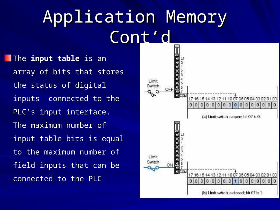
The input table is an array
of bits that stores the status
of digital inputs connected to
the PLC’s input interface.
The maximum number of
input table bits is equal to the
maximum number of field
inputs that can be connected
to the PLC

Application Memory Cont’dApplication Memory Cont’dThe output table is an array of
bits that controls the status of
digital output devices that are
connected to the PLC’s output
interface. The maximum number
of bits available in the output
table equals the maximum
number of output field devices
that can interface with the PLC.

I/O ModulesI/O Modules
Input and output (I/O) modules connect the PLC to Input and output (I/O) modules connect the PLC to
sensors and actuators.sensors and actuators.
Provide isolation for the low-voltage, low-current signals Provide isolation for the low-voltage, low-current signals
that the PLC uses internally from the higher-power that the PLC uses internally from the higher-power
electrical circuits required by most sensors and actuators.electrical circuits required by most sensors and actuators.
Wide range of I/O modules available including: digital Wide range of I/O modules available including: digital
(logical) I/O modules and analog (continuous) I/O (logical) I/O modules and analog (continuous) I/O
modules.modules.

Inputs ModulesInputs Modules
Inputs come from sensors that translate physical or Inputs come from sensors that translate physical or
chemical phenomena into electrical signals.chemical phenomena into electrical signals.
The simplest form of inputs are digital/discrete in AC/DC.The simplest form of inputs are digital/discrete in AC/DC.
In smaller PLCs the inputs are normally built in and are In smaller PLCs the inputs are normally built in and are
specified when purchasing the PLC.specified when purchasing the PLC.
For larger PLCs the inputs are purchased as modules, or For larger PLCs the inputs are purchased as modules, or
cards, with 8,16, 32, 64, 96 inputs of the same type on cards, with 8,16, 32, 64, 96 inputs of the same type on
each card.each card.

Inputs Modules Inputs Modules Cont’dCont’d The list below shows typical ranges for input The list below shows typical ranges for input
voltages.voltages.
5 Volts DC TTL level 5 Volts DC TTL level
24 Volts AC/DC24 Volts AC/DC
48 Volts AC/DC48 Volts AC/DC
110 Volts AC/DC110 Volts AC/DC
220 Volts 220 Volts AC/DCAC/DC
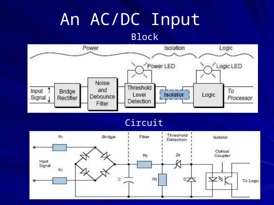
An AC/DC Input Block diagram
Circuit
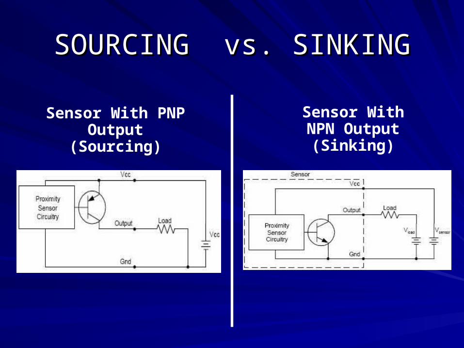
SOURCING vs. SINKINGSOURCING vs. SINKING
Sensor With PNP Output
(Sourcing)
Sensor With NPN Output
(Sinking)

Sinking DC InputsSinking DC Inputs
When a PLC input card does not have a common but it has a V+
instead, it can be used for NPN sensors. In this case the current
will flow out of the card (sourcing) and we must switch it to ground.
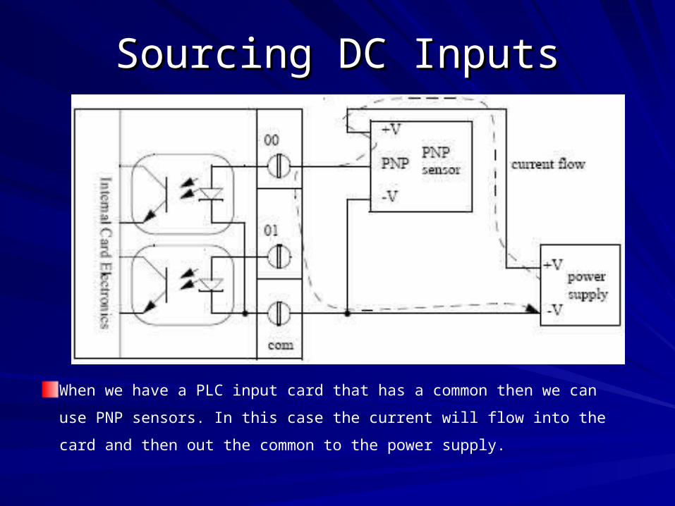
Sourcing DC InputsSourcing DC Inputs
When we have a PLC input card that has a common then we can
use PNP sensors. In this case the current will flow into the card
and then out the common to the power supply.

RulesRules
Sourcing field devices must be connected to
sinking I/O cards
Sinking field devices must be connected to
sourcing I/O cards

Device connectionsfor an AC input module for DC input module

18/04/2318/04/23
Input DevicesInput Devices
PushbuttonsPushbuttons
Selector SwitchesSelector Switches
Limit SwitchesLimit Switches
Level SwitchesLevel Switches
Photoelectric SensorsPhotoelectric Sensors
Proximity SensorsProximity Sensors
Motor Starter ContactsMotor Starter Contacts
Relay ContactsRelay Contacts
Thumbwheel SwitchesThumbwheel Switches

Outputs ModulesOutputs ModulesOutput modules rarely supply any power, but instead act as Output modules rarely supply any power, but instead act as
switches.switches.
External power supplies are connected to the output card and External power supplies are connected to the output card and
the card will switch the power on or off for each output.the card will switch the power on or off for each output.
A common choice when purchasing output cards is A common choice when purchasing output cards is relays, relays,
transistors or triacstransistors or triacs..
Relay are the most flexible output devices. They are capable Relay are the most flexible output devices. They are capable
of switching both AC and DC outputs. But, they are slower, of switching both AC and DC outputs. But, they are slower,
cost more, and they will wear out after millions of cycles. cost more, and they will wear out after millions of cycles.

An AC Output
Circuit

DC OutputDC Output
As in DC inputs, DC output modules may have either sinking or
sourcing configurations. If a module has a sinking
configuration, current flows from the load into the module’s
terminal, switching the negative (return or common) voltage to
the load. The positive current flows from the load to the
common via the module’s power transistor.
In a sourcing module configuration, current flows from the
module into the load, switching the positive voltage to the load

An Example of a 24Vdc Output Card With a Voltage Input (Sourcing)

An Example of a 24Vdc Output Card (Sinking)

RelaysRelays
When using relay outputs it is possible to have each output isolated from the
next. A relay output card could have AC and DC outputs beside each other.
Relay outputs are usually used to control up to 2 amps or when a very low
resistance is required. Transistor outputs are open collector common emitter
or emitter follower

An Example of a Relay Output Card

OutputsOutputs Typical output voltages are listed below, Typical output voltages are listed below,
5 Volts DC TTL level5 Volts DC TTL level
24 Volts AC/DC 24 Volts AC/DC
48 Volts AC/DC48 Volts AC/DC
110 Volts AC/DC110 Volts AC/DC
220 Volts 220 Volts AC/DCAC/DC
WARNING: Always check rated voltages and currents for PLCs and WARNING: Always check rated voltages and currents for PLCs and
never exceed.never exceed.

18/04/2318/04/23
Output DevicesOutput Devices
ValvesValves
Motor StartersMotor Starters
SolenoidsSolenoids
Control RelaysControl Relays
AlarmsAlarms
LightsLights
FansFans
HornsHorns
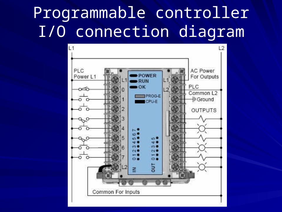
Programmable controller I/O connection diagram

Analogue CardsAnalogue Cards
Typical Analogue Input Typical Analogue Input
signals are:signals are:
– Flow sensorsFlow sensors
– Humidity sensorsHumidity sensors
– Pressure sensorsPressure sensors
– Temperature sensorsTemperature sensors
– VibrationVibration
Analogue Output signals Analogue Output signals
control:control:
– Analogue ValvesAnalogue Valves
– Variable Speed DrivesVariable Speed Drives
Typical Analogue Signal Typical Analogue Signal
LevelsLevels
– 4 - 20mA4 - 20mA
– 1 - 5 Vdc1 - 5 Vdc
– 0 - 10 Vdc0 - 10 Vdc
– -10 – 10Vdc-10 – 10Vdc

Analogue Inputs/OutputsAnalogue Inputs/Outputs
Analogue input cards convert continuous signals via a Analogue input cards convert continuous signals via a
A/D converter into discrete values for the PLCA/D converter into discrete values for the PLC
Analogue output cards convert digital values in then PLC Analogue output cards convert digital values in then PLC
to continuous signals via a D/A converter.to continuous signals via a D/A converter.
Resolution can be important in choosing an applicable Resolution can be important in choosing an applicable
cardcard

Programming DevicesProgramming DevicesPLC manufacturers have always maintained an easy human
interface for program entry. This means that users do not have to
spend much time learning how to enter a program, but rather they
can spend their time programming and solving the control problem.
Most PLCs are programmed using very similar instructions. The
only difference may be the mechanics associated with entering the
program into the PLC, which may vary from manufacturer to
manufacturer
The two basic types of programming devices are:
– Mini-programmers
– personal computers

Mini-ProgrammersMini-Programmers

Mini-Programmers Cont’d Mini-Programmers Cont’d
Mini-programmers, also known as handheld or manual
programmers, are an inexpensive and portable way to program
small PLCs (up to 128 I/O).
Mini-programmers can also be useful tools for starting up, changing,
and monitoring the control logic
Some mini-programmers offer removable memory cards or
modules, which store a complete program that can be reloaded at
any time into any member of the PLC family
Most mini-programmers are designed so that they are compatible
with two or more controllers in a product family

Personal ComputerPersonal ComputerCommon usage of the personal computer (PC)
in our daily lives has led to the practical
elimination of dedicated PLC programming
devices.
Due to the personal computer’s general-
purpose architecture and standard operating
system, most PLC manufacturers provide the
necessary PC software to implement ladder
program entry, editing, documentation, and
real-time monitoring of the PLC’s control
program.

Selecting a PLCSelecting a PLCNumber of logical inputs and outputsNumber of logical inputs and outputs
MemoryMemory
Number of special I/O modulesNumber of special I/O modules
Expansion CapabilitiesExpansion Capabilities
Scan TimeScan Time
CommunicationCommunication
SoftwareSoftware
SupportSupport
Dollars Dollars

Example of PLC SpecificationsExample of PLC Specifications

ManufacturesManufactures
OMRONOMRON
Allen BradleyAllen Bradley
Schneider (Modicon, Telemecanique, Square D)Schneider (Modicon, Telemecanique, Square D)
GE FanucGE Fanuc
SiemensSiemens
Automation Direct (Koyo)Automation Direct (Koyo)
ToshibaToshiba
MitsubishiMitsubishi
HitachiHitachi
Major BrandsMajor Brands

Programming PLC’sProgramming PLC’s
The purpose of a PLC Program is to The purpose of a PLC Program is to control the state of PLC control the state of PLC
outputs based on the current condition of PLC Inputsoutputs based on the current condition of PLC Inputs
A program is a connected series of instructions written in a
language that the PLC can understand.
There are three forms of program format:
– instruction: a word/mnemonic entry system
– Ladder: a graphical program construction method using a relay
logic symbols
– SFC (Sequential Function Chart) :a flow chart style of STL
(STep Ladder) program entry

Programming PLC’s Cont’dProgramming PLC’s Cont’d
Not all programming tools can work in all programming forms.
Generally hand held programming panels only work with
instruction format while most graphic programming tools will work
with both instruction and ladder format. Specialist programming
software will also allow SFC style programming.

Programming PLC’s Cont’dProgramming PLC’s Cont’d

Ladder Logic ConceptsLadder Logic Concepts
| | |/|
Read / Conditional Instructions
Write / Control Instructions
| | |/|
| | |/|
| |
| | |/| ( )
| |
( )
( )
( )
( )
| |
Start (Rung #1)
End (Rung #5)

Ladder Logic ConceptsLadder Logic ConceptsThe vertical line of the diagram represent the power The vertical line of the diagram represent the power railsrailsEach rung on the ladder defines one operation in Each rung on the ladder defines one operation in the control processthe control processLadder diagram is read from left to right and from Ladder diagram is read from left to right and from top to bottomtop to bottomEach rung must start with an input or inputs and Each rung must start with an input or inputs and must end with at least one outputmust end with at least one outputOne device can appear in more than one rung of One device can appear in more than one rung of ladder ladder Inputs and outputs are all identified by their address Inputs and outputs are all identified by their address the notation used depending on the plc manufacturethe notation used depending on the plc manufacture
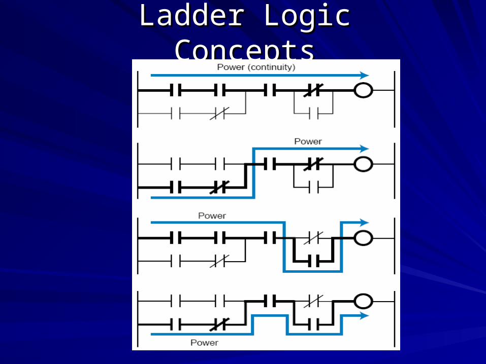
Ladder Logic ConceptsLadder Logic Concepts

Advantages Of PLCAdvantages Of PLC
The advantages they offer are:The advantages they offer are:
– Cost effective for controlling complex systemsCost effective for controlling complex systems
– Flexible and can be reapplied to control other systems Flexible and can be reapplied to control other systems
quickly and easilyquickly and easily
– Trouble shooting aids make programming easier and Trouble shooting aids make programming easier and
reduce downtimereduce downtime
– Reliable components, ensure operation for yearsReliable components, ensure operation for years
– Variety of I/O interfacesVariety of I/O interfaces

– Small sizeSmall size
– Growing with technology, faster scan times, capability etcGrowing with technology, faster scan times, capability etc
– Quick I/O disconnects that aids in field servicingQuick I/O disconnects that aids in field servicing
– Software Timers/Counter, RelaysSoftware Timers/Counter, Relays
– Clean failure modeClean failure mode
– On-line programmingOn-line programming
– Availability of replacement partsAvailability of replacement parts
Advantages Of PLC Cont’dAdvantages Of PLC Cont’d

Input DevicesInput DevicesThe most common class of input interfaces is digital (or
discrete).
Discrete input interfaces connect digital field input
devices (those that send noncontinuous, fixed-variable
signals) to input modules of programmable controller.
The discrete, noncontinuous characteristic of digital input
interfaces limits them to sensing signals that have only two
states (ON/OFF, OPEN/CLOSED, TRUE/FALSE). To an
input interface circuit, discrete input devices are
essentially switches that are either open or closed,
signifying either 1 (ON) or 0 (OFF).

Input Devices Cont’dInput Devices Cont’d
Analog signals have an infinite number of states.
Temperature, for example, is an analog signal because it
continuously changes by infinitesimal amounts.
Consequently, a change from 70°F to 71°F is not just
one change of 1°F, but rather an infinite number of
smaller changes of a fraction of a degree.
Analog input modules digitize analog input signals,
thereby bringing analog information into the PLC

Mechanical SwitchMechanical SwitchThe mechanical switch generates an on/off signal or signals as a
result of some mechanical input causing the switch to open or
close
Switches are available with normally open (NO) or normally close
(NC)
NO contact has its contact open in the absence of a mechanical
input and the mechanical input is used to close the switch
NC contact has its contact closed in the absence of a mechanical
input and the mechanical input is used to open the switch

Mechanical Switch cont’dMechanical Switch cont’d
2.2. Limit switchLimit switch
1.1. On/Off switch (On/Off switch (Toggle switch)

Mechanical Switch cont’dMechanical Switch cont’d
3.3. Limit switchLimit switch
Proximity switchesProximity switches
Proximity sensors are discrete sensors that sense when an object has come near to the sensor face. There are four fundamental types of proximity sensors the inductive proximity sensor, the capacitive proximity sensor, the ultrasonic proximity sensor, and the optical proximity sensor.

Inductive Proximity Sensor
Inductive proximity sensors operate on the principle that
the inductance of a coil vary as a metallic (or
conductive) object is passed near to it. Because of this
operating principle, inductive proximity sensors are only
used for sensing metal objects. They will not work with
non-metallic materials.
Small diameter sensors (approximately ¼” in diameter)
have typical sensing ranges in the area of 1mm, while
large diameter sensors (approximately 3" in diameter)
have sensing ranges in the order of 50mm or more

Inductive Proximity Sensor cont’d

Capacitive Proximity Sensor
Capacitive proximity sensors are available in shapes and
sizes similar to the inductive proximity sensor
capacitive proximity sensors will sense both metallic and
non-metallic objects.
The principle of operation of the sensor is that an internal
oscillator will not oscillate until a target is moved close to
the sensor face. The target varies the capacitance of a
capacitor in the face of the sensor that is part of the
oscillator circuit.

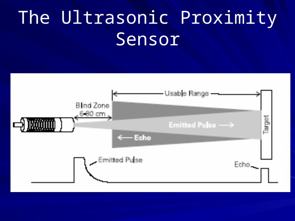
The Ultrasonic Proximity Sensor
An ultrasonic “ping” is sent from the face of the sensor. If
a target is located in front of the sensor and is within
range, the ping will be reflected by the target and
returned to the sensor.
When an echo is returned, the sensor detects that a
target is present, and by measuring the time delay
between the transmitted ping and the returned echo, the
sensor can calculate the distance between the sensor
and the target.
The Ultrasonic Proximity Sensor

Optical Proximity Sensor
Optical sensors are an extremely popular method of providing discrete-output sensing of objects. Since the sensing method uses light, it is capable of sensing any objects that are opaque.
They operate over long distances (as opposed to inductive or capacitive proximity sensors), will sense in a vacuum (as opposed to ultrasonic sensors), and can sense any type of material no matter whether it is metallic or nonmetalic
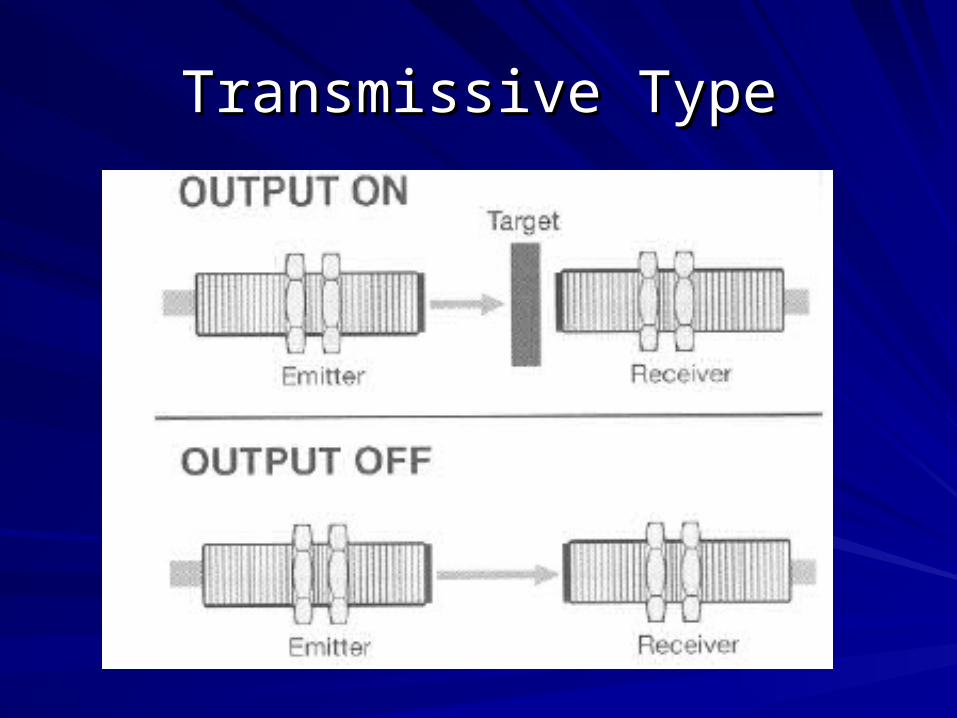
Transmissive TypeTransmissive Type

Reflective TypeReflective Type

BenefitsBenefits
The benefits achieved with programmable The benefits achieved with programmable
controllers will grow with the individual using controllers will grow with the individual using
them: them:
““The more you learn about PLC’s, the more you The more you learn about PLC’s, the more you
will be able to solve other control problems.”will be able to solve other control problems.”

Thank you….Thank you….
Questions ?Questions ?