propulsor configuration for increased efficiency
TRANSCRIPT

Propulsor configuration for increased efficiency
2
Content
Chapter 1:Introduction………………………………………………………1
Chapter 2:Devices before the propeller……………………………………..8
The wake equalizing duct…………………………………………………...8
Grothues spoilers…………………………………………………………..14
Chapter 3:Devices at the propeller………………………………………...16
Ducted propellers…………………………………………………...……..16
Application………………………………………………………………...25
Grim vane wheels………………………………………………………….32
Chapter 4: Devices after the propeller…………………….………………38
Contra-rotating propellers…………………………………………………38
Chapter 5: Conclusion…………………………………………………….45
Bibliography………………………………………………………………46
3
Chapter 1
Introduction
Great increases in the cost of fuel and the advent of very large tankers
and bulk carriers have focused the attention, during the last decades, on
means to enhance the efficiency of ship propulsion. An obvious way of
obtaining an efficiency increase is to use propellers of large diameter driven
by engines at low revolutions. Such a solution is, however, in many cases
not practically possible. This has then given impulse to the study and
adoption of unconventional propulsion arrangements, consisting, in general,
of static or moving surfaces in the vicinity of propellers.
A distinct indication of the serious and extensive activity in the
development and use of unconventional propulsors may be seen in the report
of the Propulsor Committee of the 19th ITTC (1990b).
Emphasis is given in the following to a variational procedure which,
in a unified fashion enables nearly optimum design of several of these
configurations.
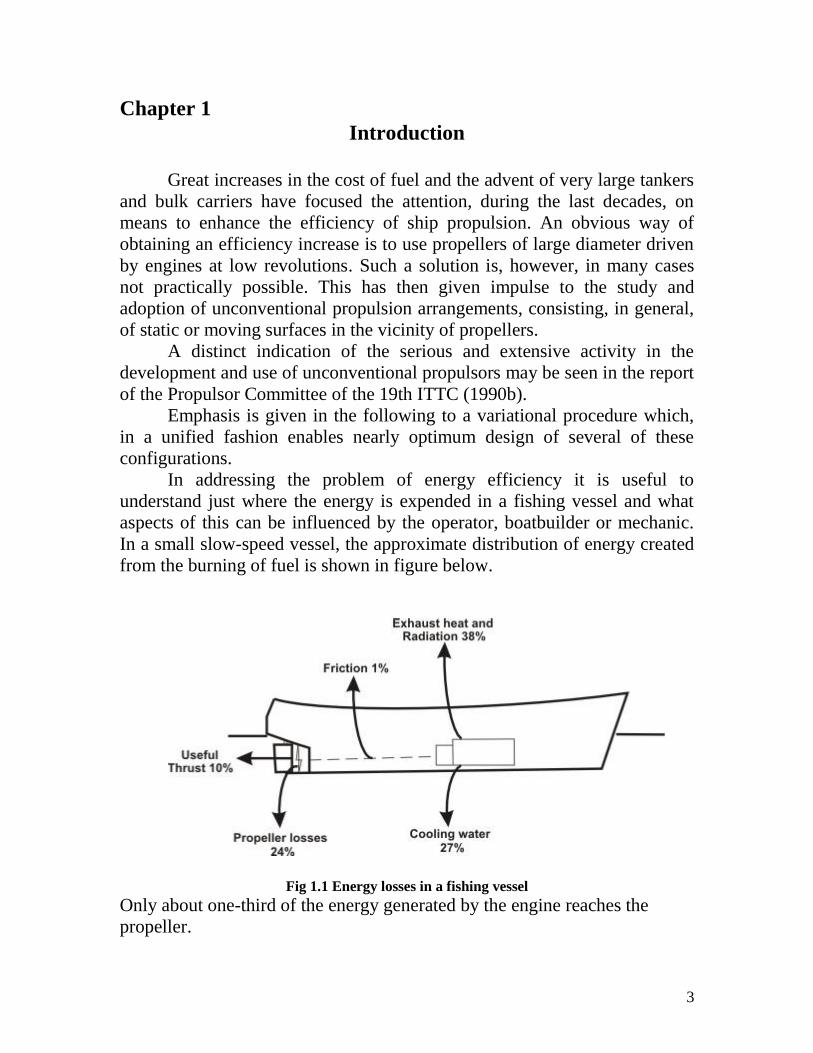
In addressing the problem of energy efficiency it is useful to
understand just where the energy is expended in a fishing vessel and what
aspects of this can be influenced by the operator, boatbuilder or mechanic.
In a small slow-speed vessel, the approximate distribution of energy created
from the burning of fuel is shown in figure below.
Fig 1.1 Energy losses in a fishing vessel
Only about one-third of the energy generated by the engine reaches the
propeller.
4
• 35 percent is used to turn the propeller;
• 27 percent to overcome wave resistance;
• 18 percent to overcome skin friction;
• 17 percent to overcome resistance from the wake;
• 3 percent to overcome air resistance.
So, where can gains be made, or at least losses minimized?
1.Engine:
Most of the energy generated by the fuel burnt in the engine is lost as heat
via the exhaust and cooling system.
2.Propeller:
The energy lost in turning the propeller is controlled by two principle factors
- the design of the propeller and its condition.
3.Mode of operation:
The effect of wave resistance, although determined principally by the
dimensions and form of the vessel, increases dramatically with speed.
Significant fuel savings can be made by maintaining a reasonable speed
for the hull, irrespective of vessel type.
4.Hull maintenance:
The significance of skin friction is controlled principally by the quality of
the hull's finish - hull roughness as well as the amount of weed and marine
growth that is allowed to accumulate on the hull. Both of these factors are
under the direct influence of the operator's maintenance programme but,
depending on the type of vessel, a significant expenditure on hull finish is
not always worthwhile.
Propulsion Efficiency:
Efficiency is conventionally thought of as the product of the open-
water efficiency of the propulsor, the hull efficiency and a factor termed the
relative-rotative efficiency.
The relative-rotative efficiency is considered as a correction to the
propulsor (propeller) efficiency arising from the alteration in the radial
distribution of loading when operating in the hull viscous and potential
wake. The hull efficiency is given in terms of the wake fraction and the
thrust-deduction fraction as (1 - t)/(l - w). Although it is necessary to
consider the total propulsive efficiency the propeller designer has mainly
influence on the propulsor efficiency to which we limit our considerations
here.
The losses for an average propeller can be traced to 3 physical phenomena:
5
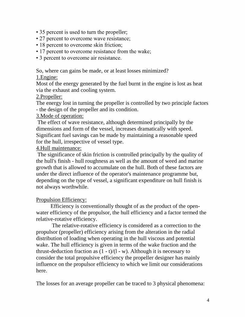
Axial losses:
A propeller generates thrust, due to the acceleration of the incoming water.
Behind the vessel, the outcoming flow mixes with the environmental flow.
Due to turbulence, energy will be lost.
Frictional losses:
Water in contact with the propeller blade surface causes friction, and thus
losses. The total blade surface, speed of rotation and surface roughness are
the dominating factors concerning frictional losses.
Rotational loses:
Rotation of the blade causes a rotation in the wake too; consequently this
energy is lost to generate a thrust in axial direction.
In addition a very significant loss is caused by the viscous drag of the blades.
Fig.1.2 Example of type of losses general ship propeller.
An indication of the relative importance of these three losses in
efficiency has been provided by Glover (1987) for representative vessels
with conventional propellers over a wide range of disc loadings as displayed
in Table 1.1.
6
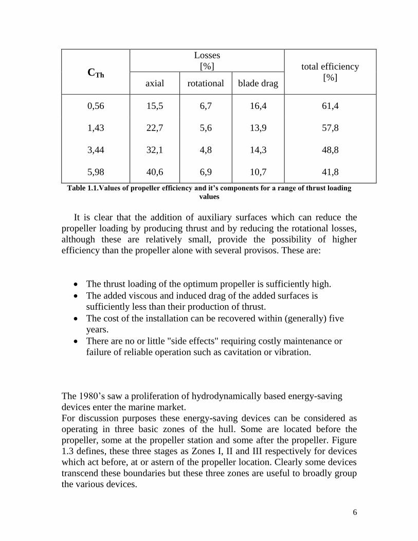
CTh
Losses
[%] total efficiency
[%] axial rotational blade drag
0,56 15,5 6,7 16,4 61,4
1,43 22,7 5,6 13,9 57,8
3,44 32,1 4,8 14,3 48,8
5,98 40,6 6,9 10,7 41,8
Table 1.1.Values of propeller efficiency and it’s components for a range of thrust loading
values
It is clear that the addition of auxiliary surfaces which can reduce the
propeller loading by producing thrust and by reducing the rotational losses,
although these are relatively small, provide the possibility of higher
efficiency than the propeller alone with several provisos. These are:
The thrust loading of the optimum propeller is sufficiently high.
The added viscous and induced drag of the added surfaces is
sufficiently less than their production of thrust.
The cost of the installation can be recovered within (generally) five
years.
There are no or little "side effects" requiring costly maintenance or
failure of reliable operation such as cavitation or vibration.
The 1980’s saw a proliferation of hydrodynamically based energy-saving
devices enter the marine market.
For discussion purposes these energy-saving devices can be considered as
operating in three basic zones of the hull. Some are located before the
propeller, some at the propeller station and some after the propeller. Figure
1.3 defines, these three stages as Zones I, II and III respectively for devices
which act before, at or astern of the propeller location. Clearly some devices
transcend these boundaries but these three zones are useful to broadly group
the various devices.
7
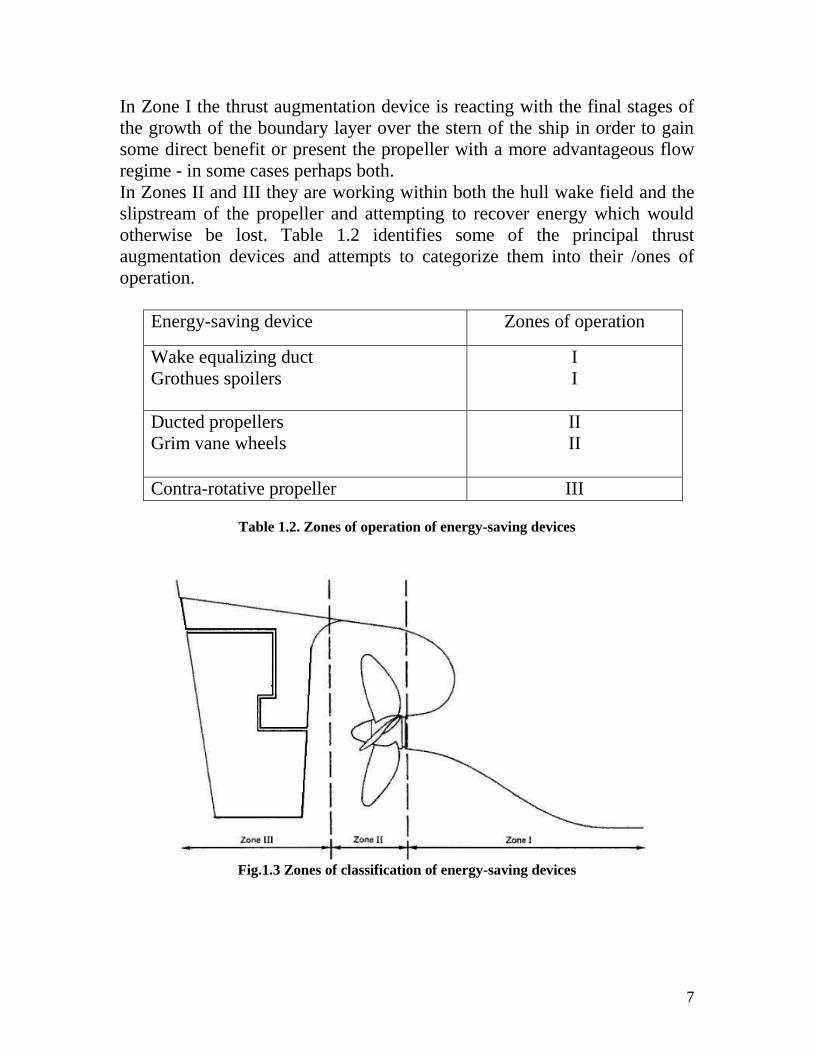
In Zone I the thrust augmentation device is reacting with the final stages of
the growth of the boundary layer over the stern of the ship in order to gain
some direct benefit or present the propeller with a more advantageous flow
regime - in some cases perhaps both.
In Zones II and III they are working within both the hull wake field and the
slipstream of the propeller and attempting to recover energy which would
otherwise be lost. Table 1.2 identifies some of the principal thrust
augmentation devices and attempts to categorize them into their /ones of
operation.
Energy-saving device Zones of operation
Wake equalizing duct
Grothues spoilers
I
I
Ducted propellers
Grim vane wheels
II
II
Contra-rotative propeller III
Table 1.2. Zones of operation of energy-saving devices
Fig.1.3 Zones of classification of energy-saving devices
8
Chapter 2:Devices before the propeller
The wake equalizing duct
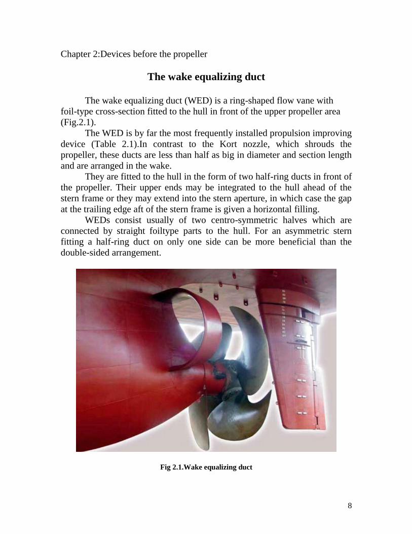
The wake equalizing duct (WED) is a ring-shaped flow vane with
foil-type cross-section fitted to the hull in front of the upper propeller area
(Fig.2.1).
The WED is by far the most frequently installed propulsion improving
device (Table 2.1).In contrast to the Kort nozzle, which shrouds the
propeller, these ducts are less than half as big in diameter and section length
and are arranged in the wake.
They are fitted to the hull in the form of two half-ring ducts in front of
the propeller. Their upper ends may be integrated to the hull ahead of the
stern frame or they may extend into the stern aperture, in which case the gap
at the trailing edge aft of the stern frame is given a horizontal filling.
WEDs consist usually of two centro-symmetric halves which are
connected by straight foiltype parts to the hull. For an asymmetric stern
fitting a half-ring duct on only one side can be more beneficial than the
double-sided arrangement.
Fig 2.1.Wake equalizing duct
9
Table 2.1.Installations of propulsion improving devices up to 1991
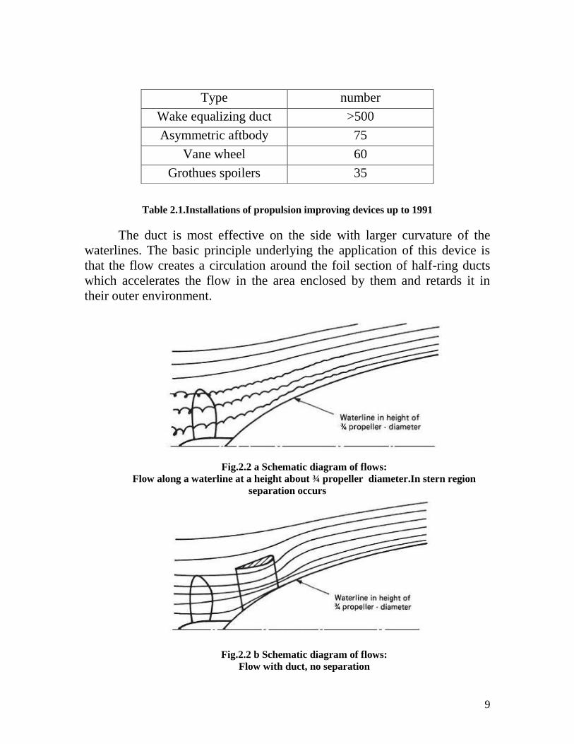
The duct is most effective on the side with larger curvature of the
waterlines. The basic principle underlying the application of this device is
that the flow creates a circulation around the foil section of half-ring ducts
which accelerates the flow in the area enclosed by them and retards it in
their outer environment.
Fig.2.2 a Schematic diagram of flows:
Flow along a waterline at a height about ¾ propeller diameter.In stern region
separation occurs
Fig.2.2 b Schematic diagram of flows:
Flow with duct, no separation
Type number
Wake equalizing duct >500
Asymmetric aftbody 75
Vane wheel 60
Grothues spoilers 35
10
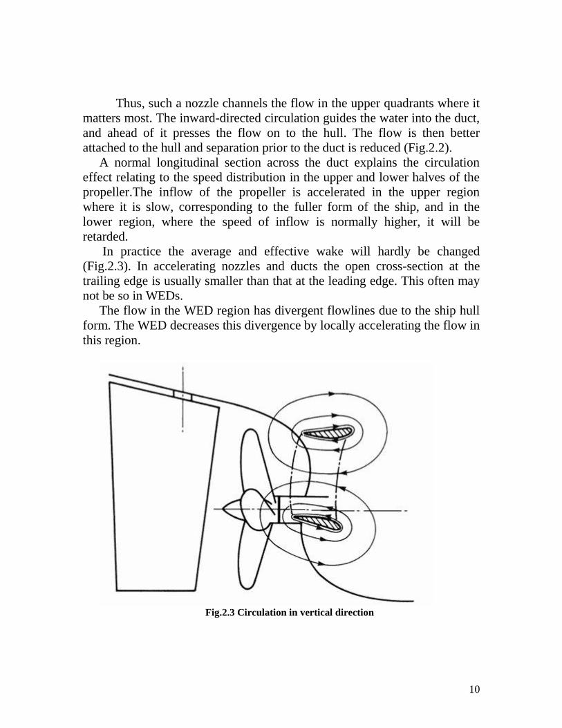
Thus, such a nozzle channels the flow in the upper quadrants where it
matters most. The inward-directed circulation guides the water into the duct,
and ahead of it presses the flow on to the hull. The flow is then better
attached to the hull and separation prior to the duct is reduced (Fig.2.2).
A normal longitudinal section across the duct explains the circulation
effect relating to the speed distribution in the upper and lower halves of the
propeller.The inflow of the propeller is accelerated in the upper region
where it is slow, corresponding to the fuller form of the ship, and in the
lower region, where the speed of inflow is normally higher, it will be
retarded.
In practice the average and effective wake will hardly be changed
(Fig.2.3). In accelerating nozzles and ducts the open cross-section at the
trailing edge is usually smaller than that at the leading edge. This often may
not be so in WEDs.
The flow in the WED region has divergent flowlines due to the ship hull
form. The WED decreases this divergence by locally accelerating the flow in
this region.
Fig.2.3 Circulation in vertical direction
11
Advantages:
The main advantage lies in power savings resulting from various effects:
Improved propeller efficiency:
Results from more axial flow and more uniform velocity distribution over
the disc area.The asymmetrical arrangement of half ducts gives a rotational
direction to the water entering the propeller, which is opposite to that which
the propeller will impart. Thus the loss from rotation energy in the propeller
wake is less.
Reduction of flow separation at the aftbody:
This effect is strong and reduces resistance and the thrust deduction
fraction.
Pre-rotation:
The nozzle axes are oriented such that the propeller inflow is given a slight
pre-rotation which counteracts the propeller rotation.
Improved steering qualities:
Results from more straightened flow to the rudder. In spade rudders the
longer upper sections become more effective because of the higher flow
velocity.
Improved course-keeping ability.
No constructional changes and no modifications in propeller design
are involved when the duct is fitted to an existing ship.
Possibility to integrate devices for ice protection to propeller:
Even without special ice protection, ducts protect propellers. Up to 1997,
almost 900 ducts had been installed, many in ships on ice-infested routes.
No damage to ducts has been reported and ice-damage to propellers has been
reduced.
Reduction of propeller-excited vibrations:
Caused by decreased propeller tip loading in upper quadrants to less than
half the amplitudes. This allows reduction of propeller clearances in new
designs. Reduced vibrations have in practice also decreased malfunctions of
electronic equipment. The reduction in vibration amplitudes by the WED is
easily explained by the velocity distribution. Larger inflow velocity means
smaller angle of attack – between profile zero lift position and inflow
direction .The hydrodynamic forces and thus pressure impulses are roughly
proportional to the angle of attack for small angles of attack. The WED also
smooths the torque and thus reduces the tendency for torsional vibrations.
12
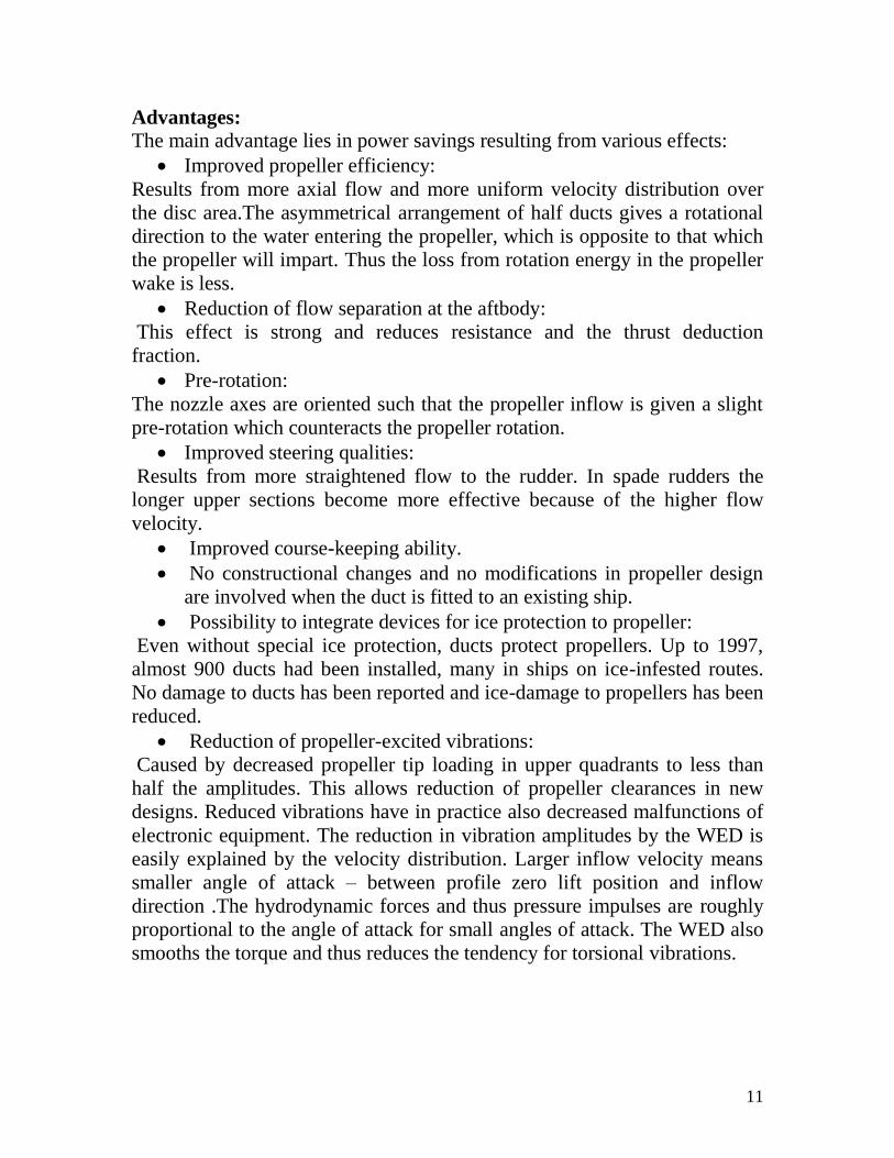
Higher speeds:
The power savings can be used to obtain higher speed. For a given speed,
the power savings are converted to a lower rate of rotation.Model tests have
determined a maximum energy saving of 14% at the same speed in several
cases.
Fig.2.4 Speed versus engine power
Reduced cavitation:
Unlike ducted propellers, which are hardly used in ocean vessels due, in
part,to problems of tip clearances and cavitation, the WED does not pose
such problems. The more uniform flow into the propeller reduces the
dangers of propeller cavitation. The duct itself is less exposed to this
problem than the rudders because of the considerably lower flow velocity in
the wake at its location, which is often less than half the ship speed. Another
advantage here is that normally the WED is considered for moderate speed
vessels with block coefficient above 0.6; fast ships, which tend to have
cavitation problems, are less suited to its use.
Cost aspects:
In newbuilds the costs of the duct can be lower than those costs saved by
choice of a smaller engine, made possible by the power savings.

13
The investment for fabrication and fitting is invariably recovered in 6–20
months, depending on ship form and fuel price.
Simpler design:
- The ship hull can be kept simpler. The stern bulb can be built
less pronounced and the counter can be placed lower. Concave waterlines
at the height of the WED are not necessary, thus the hull is cheaper to
produce and the resistance lower.
- Simpler propellers with fewer blades and less skew. The
propellers can be more highly loaded at the tips. Thus the propellers are
cheaper, yet more efficient.
Fig 2.5. Axial velocity distributions at the propeller plane, without and with the duct
Disadvantages:
Above certain speeds, the drag created by the ducts is greater than the
advantages.
14
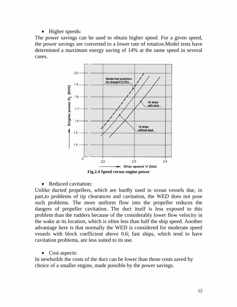
Grothues spoilers
This device, named after its inventor, Grotheus-Spork (1988), consists
of a set of fins attached to the hull ahead of the propeller. They consist of a
set of triangular fins attached to the hull just ahead of the propeller, as show
in Fig.2.6.The purpose is to straighten the boundary layer flow right before
the propeller, thus creating direct thrust and improving the propeller
efficiency. These devices are also referred to as Grothues Fins.
Fig.2.6 Grothues spoilers
The idea is to straighten the flow before it enters the propeller plane.
The fins provide thrust and the propeller inflow is more axially directed. In
principle such fins may be beneficial: wake velocities in transverse direction
create a non-uniform propeller loading and is lost energy. They may even
avoid separation. The problem is control of the flow around these fins. When
they are not in the proper position their effect is negative, and even if they
are, the own viscous drag of he fins may annihilate any gains.
The fins are designed to improve the flow into the propeller by
converting the vertical component of the flow due to bilge vortices into a
horizontal flow, and thus recover energy. The fins produce a small forward
thrust, increase the mass flow through the propeller disc and reduce angular
velocity variations in the flow. Grothues spoilers thereby reduce resistance,
improve propeller efficiency and reduce vibration.
The shape, position and number of fins must be determined by model
tests. Power savings ranging from about 3 percent for fine vessels with low
breadth-draught ratios to about 9 percent for full tankers are possible using
Grothues spoilers, greater improvements being achieved in the ballast
condition.
15
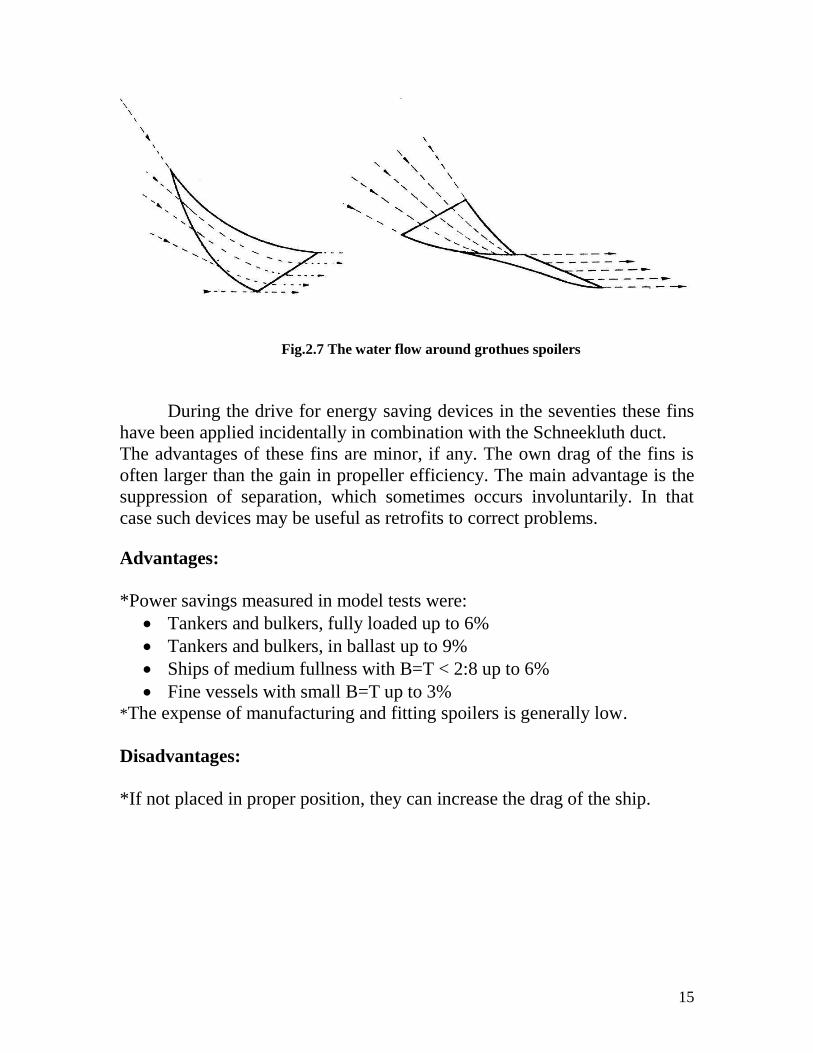
Fig.2.7 The water flow around grothues spoilers
During the drive for energy saving devices in the seventies these fins
have been applied incidentally in combination with the Schneekluth duct.
The advantages of these fins are minor, if any. The own drag of the fins is
often larger than the gain in propeller efficiency. The main advantage is the
suppression of separation, which sometimes occurs involuntarily. In that
case such devices may be useful as retrofits to correct problems.
Advantages:
*Power savings measured in model tests were:
Tankers and bulkers, fully loaded up to 6%
Tankers and bulkers, in ballast up to 9%
Ships of medium fullness with B=T < 2:8 up to 6%
Fine vessels with small B=T up to 3%
*The expense of manufacturing and fitting spoilers is generally low.
Disadvantages:
*If not placed in proper position, they can increase the drag of the ship.
16
Chapter 3:Devices at the propeller
Ducted propellers
To obtain the most thrust, a propeller must move as much water as
possible in a given time. A nozzle will assist the propeller in doing this,
especially when a high thrust is needed at a low ship speed. As we already
know, as the propeller blades rotate in the water, they generate high-pressure
areas behind the each blade and low pressure areas in front, and it is this
pressure differential that provides the force to drive the vessel. However,
losses occur at the tip of each blade as water escapes from the high pressure
side of the blade to the low pressure side, resulting in little benefit in terms
of pushing the vessel forward. The presence of a close fitting duct around
the propeller reduces these loses by restricting water flow to the propeller
tips.
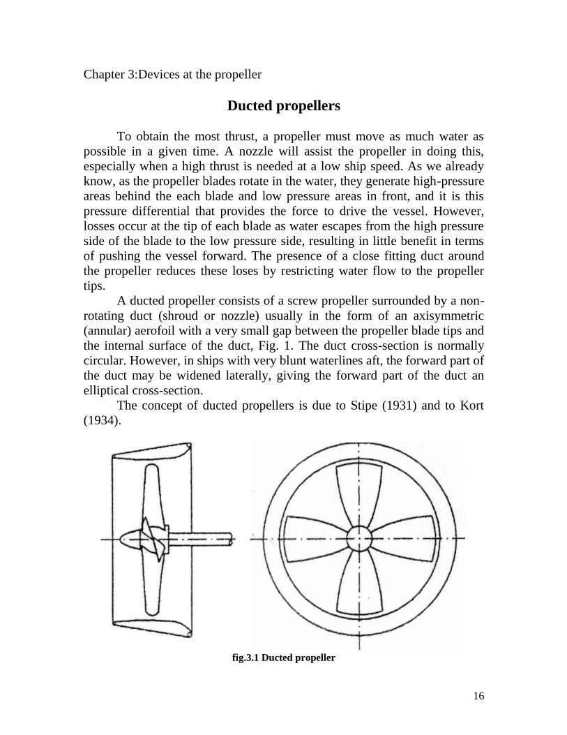
A ducted propeller consists of a screw propeller surrounded by a non-
rotating duct (shroud or nozzle) usually in the form of an axisymmetric
(annular) aerofoil with a very small gap between the propeller blade tips and
the internal surface of the duct, Fig. 1. The duct cross-section is normally
circular. However, in ships with very blunt waterlines aft, the forward part of
the duct may be widened laterally, giving the forward part of the duct an
elliptical cross-section.
The concept of ducted propellers is due to Stipe (1931) and to Kort
(1934).
fig.3.1 Ducted propeller
17
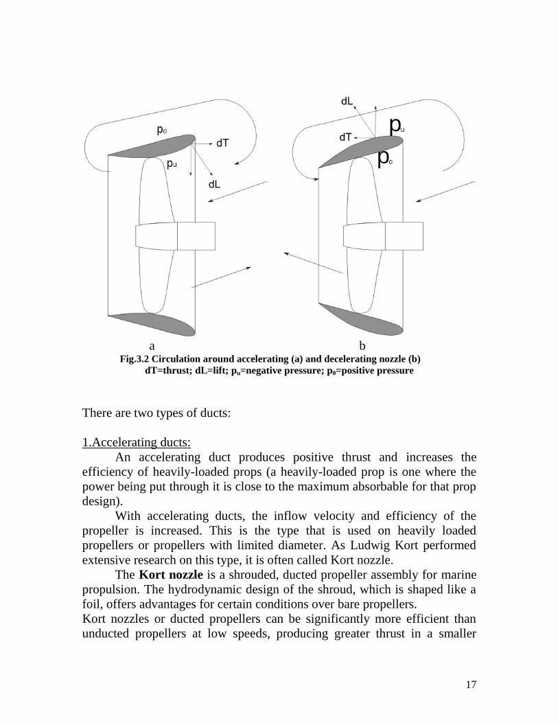
a b Fig.3.2 Circulation around accelerating (a) and decelerating nozzle (b)
dT=thrust; dL=lift; pu=negative pressure; p0=positive pressure
There are two types of ducts:
1.Accelerating ducts:
An accelerating duct produces positive thrust and increases the
efficiency of heavily-loaded props (a heavily-loaded prop is one where the
power being put through it is close to the maximum absorbable for that prop
design).
With accelerating ducts, the inflow velocity and efficiency of the
propeller is increased. This is the type that is used on heavily loaded
propellers or propellers with limited diameter. As Ludwig Kort performed
extensive research on this type, it is often called Kort nozzle.
The Kort nozzle is a shrouded, ducted propeller assembly for marine
propulsion. The hydrodynamic design of the shroud, which is shaped like a
foil, offers advantages for certain conditions over bare propellers.
Kort nozzles or ducted propellers can be significantly more efficient than
unducted propellers at low speeds, producing greater thrust in a smaller
18
package. Tugboats are the most common application for Kort nozzles as
highly loaded propellers on slow moving vessels benefit the most.
The additional shrouding adds drag, however, and Kort nozzles lose
their advantage over propellers at about 10 knots (18.5 km/h).
Kort nozzles may be fixed, with directional control coming from a rudder set
in the water flow, or pivoting, where their flow controls the vessel's steering.
Shrouding of this type is also beneficial to navigation in ice fields since it
protects the propeller tips to some extent.
In a Kort nozzle, the inflow velocity is increased, reducing pressure.
This lowers thrust and torque of the propeller. At the same time, a
circulation occurs, resulting in an inward aimed force, that has a forward
component. The duct therefore has a positive thrust. This is normally larger
than the thrust reduction of the propeller. The small clearance between the
propeller and duct reduces tip vortex, increasing efficiency.
As drag increases with increasing speed, eventually this will become
larger then the added thrust. Vessels that normally operate above this speed
are therefore normally not fitted with ducts. When towing, tugboats sail with
low speed and heavily loaded propellers, and are often fitted with ducts.
Bollard pull can increase up to 30% with ducts.
Accelerating ducts, Fig. 3.2 (a), are used in heavily loaded propellers.
The small clearance between the propeller blade tips and the duct suppresses
the trailing free vortices shed by the blades, the bound vortices on the blades
joining the bound vortex ring on the duct. The shape of the accelerating duct
at the forward end (leading edge) increases the mass flow to the propeller.
At the after end, the duct is so shaped that the cross-section increases going
aft and the normal slipstream contraction is suppressed. The increased
inflow velocity causes a decrease in the thrust and torque of the propeller.
At the same time, a circulation develops around the duct section
resulting in an inward directed force which has a forward component, the
duct thrust. The duct also has a drag directed aft, and this should be
substantially less than the duct thrust. The total thrust of the propeller and
duct taken together is then usually greater than that of an equivalent open
propeller (i.e. one without a duct) whereas the torque is smaller. The
efficiency of the ducted propeller is therefore greater than that of the open
propeller. The improved efficiency of the ducted propeller may also be
explained by the reduced kinetic energy losses in the slipstream due to the
suppression of the trailing vortices and the reduction of the slipstream
contraction.
19
2.Decelerating ducts:
With the second type,Fig.3.2 (b), the inflow velocity into the propeller
is reduced, whereby pressure at the propeller location is increased, and
delays the cavitation.
The duct has a circulation around it which produces an outward
directed lift with a component directed aft, i.e. the duct thrust is negative.
The efficiency of a ducted propeller with a decelerating duct is lower than
that of an equivalent open propeller, but its cavitation properties are su-
perior. Decelerating ducts are therefore used for high speed hydrodynarnic
bodies in which it is necessary to minimise cavitation and underwater noise.
A decelerating duct produces a negative thrust and is valuable for
reducing cavitation. A decelerating duct is a major contributor to noise
reduction which is why it is getting more popular with modern warship
designs. The most used decelerating ducts systems the ones are called pump-
jets, used in high-speed or shallow draft operating ships.
Theoretical comparison between accelerating and decelerating ducts:
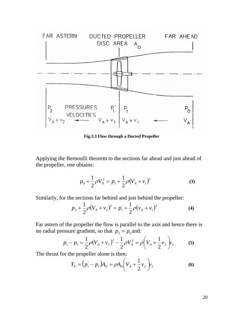
An insight into the performance of ducted propellers is provided by
applying the axial momentum theory. Consider the fluid column flowing
through a ducted propeller of cross-sectional area A0, Fig. 3.3.
The pressures far ahead, just ahead, just behind and far behind the
propeller are '
110 ,, ppp and 2p respectively, the propeller being regarded as
an actuator disc causing'an abrupt increase in pressure from 1p to '
1p .The
velocities of the fluid with respect to the propeller far ahead, at the propeller
and far behind are 1, vVV AA and 2vVA . The mass of fluid flowing through
the propeller per-unit time is:
1vVm AO (1)
The total thrust of the propeller is equal to the rate of change of momentum
of the fluid in the slipstream, and is given by:
AA VvVmT 2 = 21 vvVAO (2)
20
Fig.3.3 Flow through a Ducted Propeller
Applying the Bernoulli theorem to the sections far ahead and just ahead of
the propeller, one obtains:
2
11
2
02
1
2
1vVpVp AA (3)
Similarly, for the sections far behind and just behind the propeller:
21
'
1
2
222
1
2
1vvpvVp AA (4)
Far astern of the propeller the flow is parallel to the axis and hence there is
no radial pressure gradient, so that 02 pp and:
22
22
21
'
12
1
2
1
2
1vvVVvVpp AAA
(5)
The thrust for the propeller alone is then:
221
'
12
1vvVAAppT AOOP
(6)
21
A thrust ratio is now defined as the ratio of the propeller thrust pT to the
total thrust Dp TTT , where DT is the thrust of the duct:
T
T
TT
T P
DP
P
A
A
V
v
V
v
1
2
1
2
1
1
(7)
The thrust loading coefficient is given by:
AAAO
A
AO
TLV
v
V
v
VA
vvVA
VA
TC 2
2
2
21
2
2
1
12
2
1
2
1
(8)
This gives the following results:
5.02
112
12
1
1 TL
A
CV
v
5.01 112
11 TL
A
CV
v
(9)
5.02
1 1112
1
TL
AAA
D CV
v
V
v
V
v
where Dv is the induced velocity due to the duct.
The delivered power of the propeller is equal to the increase in the kinetic
energy of the fluid per unit time:
22
22
1
2
1AAD mVvVmP 221
2
1
2
1vvVvVA AAO
(10)
The ideal efficiency of the ducted propeller is then:
221
21
2
1
2
1vvVvVA
VvvVA
P
TV
AAO
AAO
D
Ai
AV
v22
1
1
1
5.011
2
TLC (11)
22
Putting '112
1ppp , the pressure coefficient at the propeller is given
by:
2
0
2
1A
p
V
ppC
2
5.0
2
11
21
TLTL CC (12)
The effect of the drag of the duct on the efficiency of the ducted propeller
can be taken into account approximately as fallows:
DAD CDlVD 2
2
1
TLAO
DAD
D
CVA
CDlV
T
DTk
2
2
2
12
1
1
TL
D
C
C
D
l41
noting that 4
2
0
DA
. Then:
5.011
241
TLTL
DiD
CC
C
D
lk
(13)
where:
DD – duct drag
D – propeller diameter
l – duct length
CD – duct drag coefficient
KD – drag correction factor
- ducted propeller efficiency including duct drag.
Conclusions:
Equations (11), (12) and (13) yield some interesting conclusions:
The ideal efficiency of the ducted propeller increases as r decreases.
In practice, reducing below a certain limit would cause the flow
past the inner surface of the duct to break down due to boundary layer
separation, resulting in a sharp drop in the efficiency of the ducted
propeller.
23
The static pressure at the propeller increases as increases, thereby
delaying cavitation. By definition, if is greater than 1 the duct has a
negative thrust.
The effect of duct drag reduces as the thrust loading of the ducted
propeller increases. For values of TLC exceeding about 1,5 the drag of
the duct is insignificant compared to the kinetic energy losses.
The effect of duct drag on efficiency can be reduced by minimising
the length of the duct. In practice, however, there is a lower limit to
the duct length for a given duct loading below which the flow through
the duct breaks down resulting in a severe degradation of
performance.
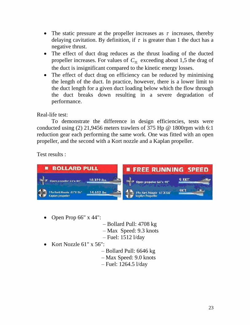
Real-life test:
To demonstrate the difference in design efficiencies, tests were
conducted using (2) 21,9456 meters trawlers of 375 Hp @ 1800rpm with 6:1
reduction gear each performing the same work. One was fitted with an open
propeller, and the second with a Kort nozzle and a Kaplan propeller.
Test results :
Open Prop 66" x 44":
– Bollard Pull: 4708 kg
– Max Speed: 9.3 knots
– Fuel: 1512 l/day
Kort Nozzle 61" x 56":
– Bollard Pull: 6646 kg
– Max Speed: 9.0 knots
– Fuel: 1264.5 l/day
24
Advantages:
At high thrust-loading coefficients, better efficiency is obtainable. For
tugs and pusher boats, efficiency improvements of around 20% are
frequently achievable. Bollard pull can be raised by more than 30%.
The reduction of propeller efficiency in a seaway is lower for nozzle
propellers than for non-ducted propellers.
Course stability is substantially improved by the nozzle.
In ‘steerable nozzle’ versions, the nozzle replaces the rudder. The hull
waterlines at nozzle height can be run further aft and thus the waterline
endings can be made finer and ship resistance reduced. The steerable
nozzle, however, has a somewhat lower efficiency than the fixed nozzle,
since the gap between propeller blade tips and nozzle internal wall must
be kept slightly larger. There is also less space for the propeller diameter,
since the steerable nozzle, unlike conventional fixed nozzles, cannot fit
into the stern counter.
Decelerating ducts minimise cavitation and underwater noise ( useful
for military ships)
Disadvantages:
Course-changing ability during astern operation is somewhat
impaired.
Owing to circulation in shallow water, the nozzle propeller tends to
draw into itself shingle and stones. Also possible is damage due to
operation in ice. This explains the infrequent application on seagoing
ships.
Due to the pressure drop in the nozzle, cavitation occurs earlier.
25
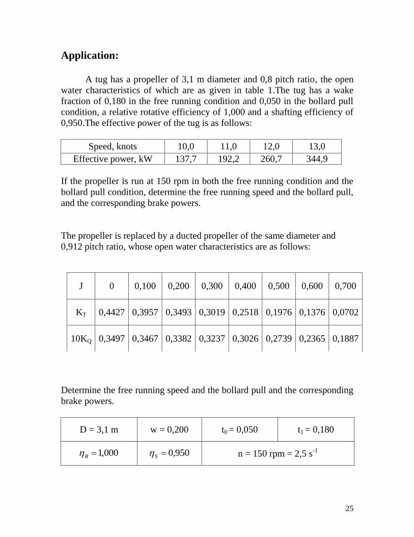
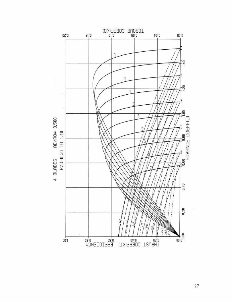
Application:
A tug has a propeller of 3,1 m diameter and 0,8 pitch ratio, the open
water characteristics of which are as given in table 1.The tug has a wake
fraction of 0,180 in the free running condition and 0,050 in the bollard pull
condition, a relative rotative efficiency of 1,000 and a shafting efficiency of
0,950.The effective power of the tug is as follows:
Speed, knots 10,0 11,0 12,0 13,0
Effective power, kW 137,7 192,2 260,7 344,9
If the propeller is run at 150 rpm in both the free running condition and the
bollard pull condition, determine the free running speed and the bollard pull,
and the corresponding brake powers.
The propeller is replaced by a ducted propeller of the same diameter and
0,912 pitch ratio, whose open water characteristics are as follows:
Determine the free running speed and the bollard pull and the corresponding
brake powers.
D = 3,1 m w = 0,200 t0 = 0,050 t1 = 0,180
000,1R 950,0S n = 150 rpm = 2,5 s-1
J 0 0,100 0,200 0,300 0,400 0,500 0,600 0,700
KT 0,4427 0,3957 0,3493 0,3019 0,2518 0,1976 0,1376 0,0702
10KQ 0,3497 0,3467 0,3382 0,3237 0,3026 0,2739 0,2365 0,1887
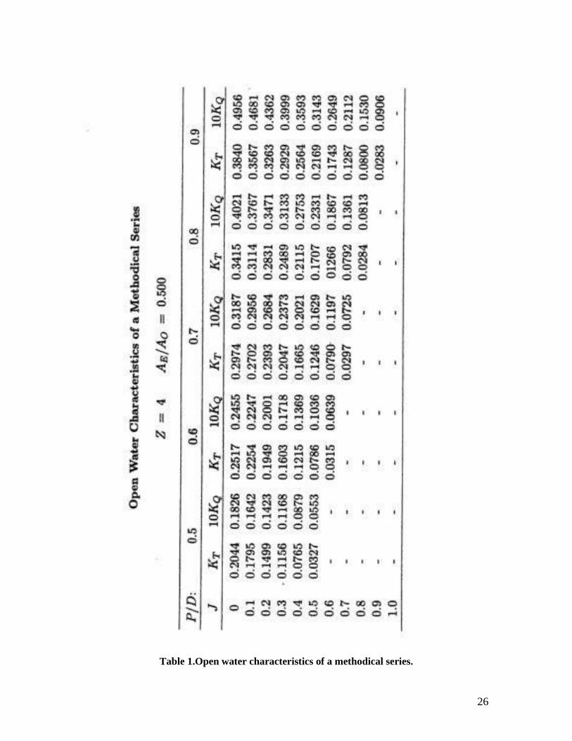
26
Table 1.Open water characteristics of a methodical series.
27
28
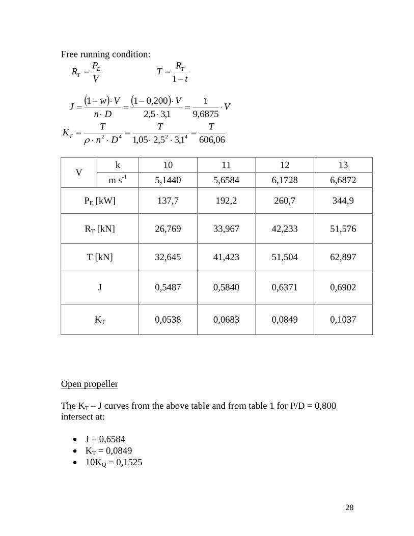
Free running condition:
V
PR E
T t
RT T
1
V
V
Dn
VwJ
6875,9
1
1,35,2
200,011
06,6061,35,205,1 4242
TT
Dn
TKT
V k 10 11 12 13
m s-1
5,1440 5,6584 6,1728 6,6872
PE [kW] 137,7 192,2 260,7 344,9
RT [kN] 26,769 33,967 42,233 51,576
T [kN] 32,645 41,423 51,504 62,897
J 0,5487 0,5840 0,6371 0,6902
KT 0,0538 0,0683 0,0849 0,1037
Open propeller
The KT – J curves from the above table and from table 1 for P/D = 0,800
intersect at:
J = 0,6584
KT = 0,0849
10KQ = 0,1525
29
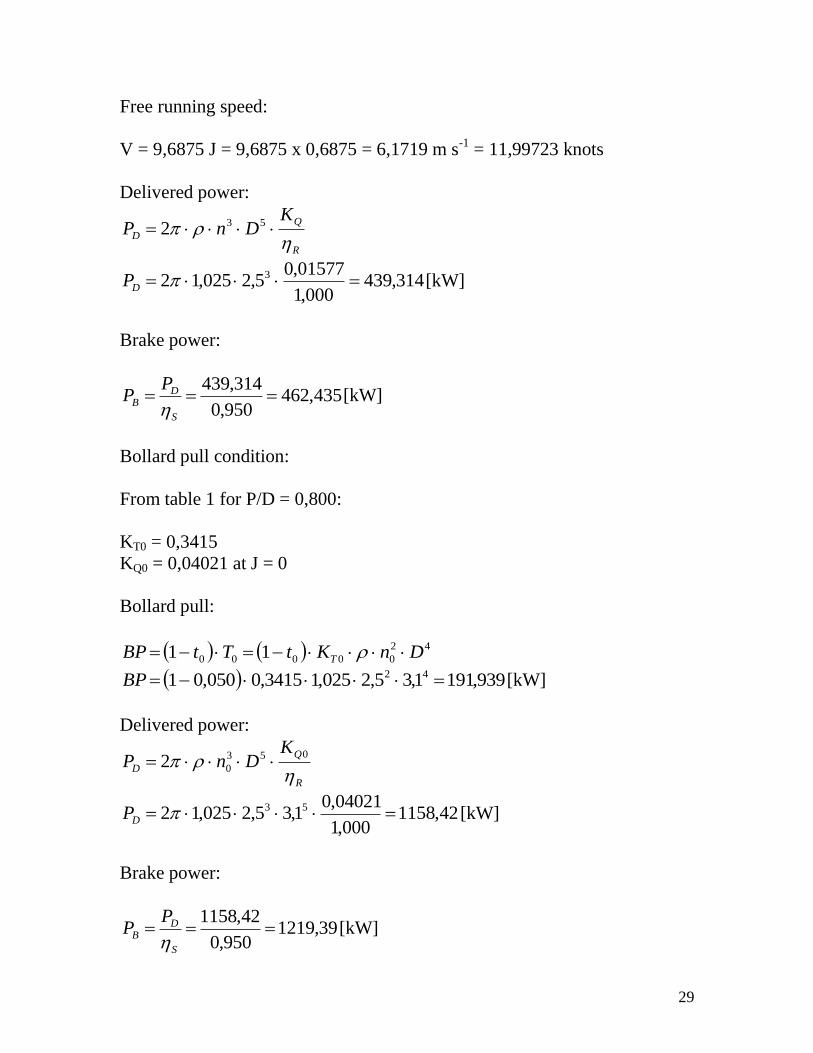
Free running speed:
V = 9,6875 J = 9,6875 x 0,6875 = 6,1719 m s-1
= 11,99723 knots
Delivered power:
R
Q
D
KDnP
532
314,439000,1
01577,05,2025,12 3 DP [kW]
Brake power:
435,462950,0
314,439
S
DB
PP
[kW]
Bollard pull condition:
From table 1 for P/D = 0,800:
KT0 = 0,3415
KQ0 = 0,04021 at J = 0
Bollard pull:
42
00000 11 DnKtTtBP T
939,1911,35,2025,13415,0050,01 42 BP [kW]
Delivered power:
R
Q
D
KDnP
053
02
42,1158000,1
04021,01,35,2025,12 53 DP [kW]
Brake power:
39,1219950,0
42,1158
S
DB
PP
[kW]
30
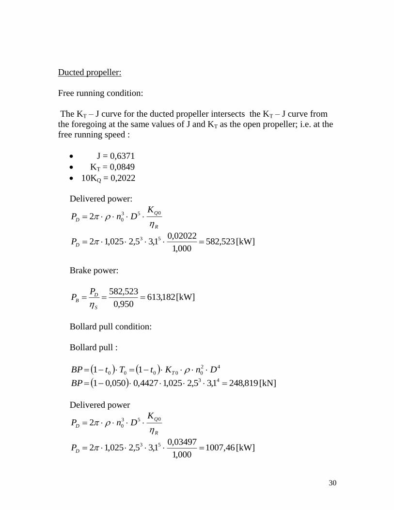
Ducted propeller:
Free running condition:
The KT – J curve for the ducted propeller intersects the KT – J curve from
the foregoing at the same values of J and KT as the open propeller; i.e. at the
free running speed :
J = 0,6371
KT = 0,0849
10KQ = 0,2022
Delivered power:
R
Q
D
KDnP
053
02
523,582000,1
02022,01,35,2025,12 53 DP [kW]
Brake power:
182,613950,0
523,582
S
DB
PP
[kW]
Bollard pull condition:
Bollard pull :
42
00000 11 DnKtTtBP T
819,2481,35,2025,14427,0050,01 43 BP [kN]
Delivered power
R
Q
D
KDnP
053
02
46,1007000,1
03497,01,35,2025,12 53 DP [kW]

31
Brake power:
484,1060950,0
46,1007
S
DB
PP
[kW]
Conclusion:
Both the open propeller and the ducted thus give the same running speed
in this example, but the ducted propeller provides a higher bollard pull at
a lower power.
32
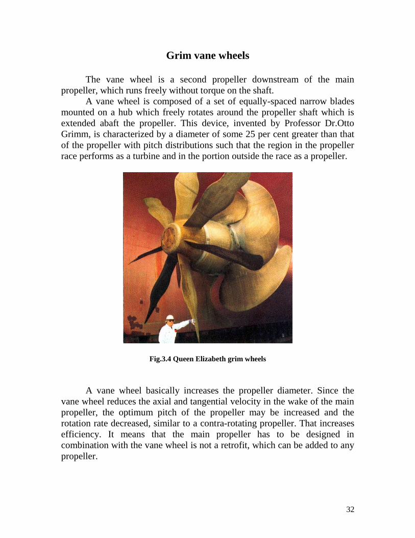
Grim vane wheels
The vane wheel is a second propeller downstream of the main
propeller, which runs freely without torque on the shaft.
A vane wheel is composed of a set of equally-spaced narrow blades
mounted on a hub which freely rotates around the propeller shaft which is
extended abaft the propeller. This device, invented by Professor Dr.Otto
Grimm, is characterized by a diameter of some 25 per cent greater than that
of the propeller with pitch distributions such that the region in the propeller
race performs as a turbine and in the portion outside the race as a propeller.
Fig.3.4 Queen Elizabeth grim wheels
A vane wheel basically increases the propeller diameter. Since the
vane wheel reduces the axial and tangential velocity in the wake of the main
propeller, the optimum pitch of the propeller may be increased and the
rotation rate decreased, similar to a contra-rotating propeller. That increases
efficiency. It means that the main propeller has to be designed in
combination with the vane wheel is not a retrofit, which can be added to any
propeller.
33
The inner part of the vane wheel, the impeller part or turbine part, has
a pitch such that the vane wheel is driven, by the wake of the main propeller.
The outer part of the blades of the vane wheel, the propeller part, has a
different pitch, which causes the vane wheel to generate thrust of the main
propeller.
Vane wheels are subjected to strong fluctuations in loading. Problems
with the strength of the blades have been encountered frequently and this has
led to its limited application.
Advantages:
Substantial recovery of rotational energy
Less resistance from rudder behind the vane wheel,that is better
relative efficiency
Greater possible jet cross-section of vane wheel, since the low rpm
rate and large number of blades enable smaller vertical clearances to
be accepted.
Less resistance from rudder behind the vane wheel. This is reflected in
the relative rotative efficiency.
Better stopping ability
Reduces cavity
Moreover, the higher rpm rate associated with the smaller diameter of
the engine-driven propeller improves the weight and cost of the
propulsion unit.
Disadvantages:
Cost of the vane
If not designed carefully, the resulting drag can create more resistance
than the energy retrieved.
Strong currents can destroy the blades of the vane wheel
It is clear that the vane wheel which rotates in the same direction as the
propeller at an angular velocity in the range of 35 to 50 per cent of that of
the propeller makes use of both the axial and the tangential momentum
losses of the propeller.
The propeller and vane wheel has a larger diameter than the propeller
alone, entraining a greater volume of water and hence an increment in
efficiency as dictated by momentum considerations. A similar increment
can, of course, be secured by using a single propeller of the same, larger
34
diameter, but this would require lower shaft speed and in addition,increased
vibratory excitation attending reduced tip clearance. In contrast, the lightly
loaded vanes can extend much nearer to the hull without producing
significant vibratory forces.
The principal parameter indicative of the gain in propulsor efficiency is
the thrust-loading coefficient ThC ,the gain rising with increasing ThC . The
minimum ThC for a zero gain in efficiency is 0.50. In practice the minimum
ThC must be greater than 1.0 to obtain a reasonably short pay-back period of
the installation costs.
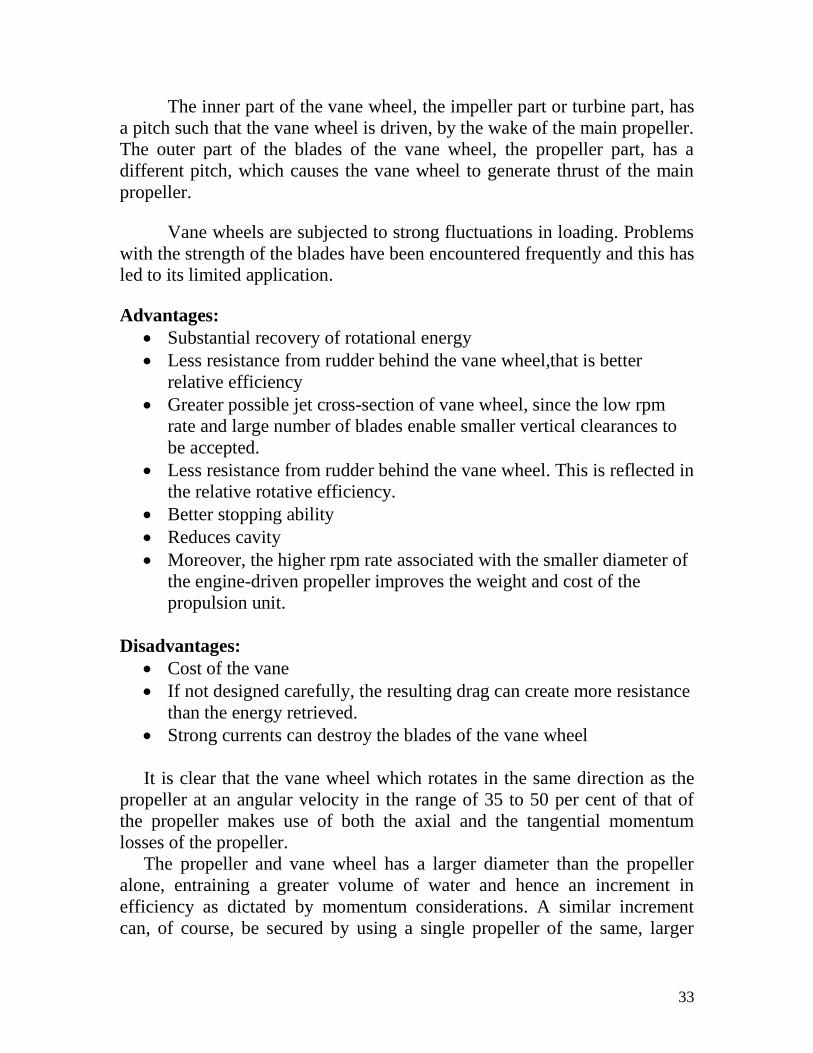
It is interesting to note that the first model tests carried out with the vane-
wheel design displayed much lower performance than predicted by Grim's
calculations. This was later understood to be caused by the low Reynolds
numbers at which open-water and particularly self-propulsion tests are
normally conducted. Later experiments by Blaurock & Jacob (1987) using
large models were conducted in the cavitation tunnel at Hamburgische
Schiffbau-Versuchsanstalt (HSVA) over a range of Reynolds numbers.
The results displayed in Figure 3.5 show the dominating effect of
Reynolds number on the gain in efficiency over a wide range in thrust-
loading coefficients.
Fig.3.5 Gain in efficiency by means of a vane wheel
predicted by model tests and achieved in full scale
35
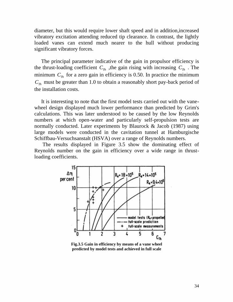
Model tests at HSVA have since then been made without the vane
wheel. The full-scale prediction of the effect of the wheel is then made by
use of Grim's theory which has been verified by many sea trials.
Fig.3.6 Optimum circulation distribution for propeller
and vane-wheel combination
These measurements have shown gains in propulsive efficiency in the
range of 7 to 10 per cent depending upon CTh as summarized in Figure 3.5.
Blaurock relates that measurements of fluctuating pressures on sister hulls in
way of the propeller without and with vane wheel showed amplitudes with
the wheel to be halved at blade frequency and some 30 per cent less at twice
blade frequency. This is ascribed to reduced propeller cavitation attending
the reduction in propeller loading.
In application of the unified variational procedure by Kerwin et al.
(1986), to determine optimum propeller and vane-wheel loading
distributions this propulsor is analogous to a pair of tandem propellers of
unequal diameter with the aft unit rotating at a rate of revolutions at a
fraction of that of the forward element and as the torque on the vane wheel is
zero, then Q2 =0, giving the constraint parameter q = 0.
The optimum radial distributions of circulations for a propeller and
vane wheel are given in Figure 3.6. The operation conditions are the same
for the single and contrarotating propeller. It is seen that the propeller
component is more lightly loaded, near the tip, relative to the single
propeller.

36
First ship to use Grim Wheels:
The first passenger ship which uses Grim Wheels was Queen
Elizabeth 2. During retrofit, the fixed-pitch propellers were replaced with
variable-pitch types.
.
The pitch of the new variable-pitch blades, however, could simply be
reversed, causing a reversal of propeller thrust while maintaining the same
direction of propeller rotation, allowing the ship better stopping times and
improved handling characteristics.
The new propellers originally were fitted with Grim Wheels, which
were free-spinning propeller blades that were fitted behind the main
propellers with long vanes protruding from the centre hub.
Fig.3.7 Propeller side view plan Sketch of the propeller
and Grim Wheel arrangement on the QE2
37
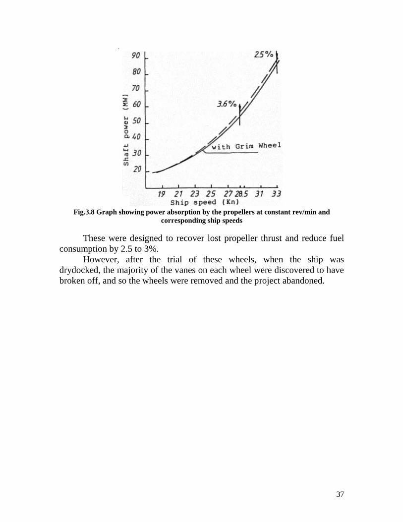
Fig.3.8 Graph showing power absorption by the propellers at constant rev/min and
corresponding ship speeds
These were designed to recover lost propeller thrust and reduce fuel
consumption by 2.5 to 3%.
However, after the trial of these wheels, when the ship was
drydocked, the majority of the vanes on each wheel were discovered to have
broken off, and so the wheels were removed and the project abandoned.
38
Chapter 4: Devices after the propeller
Contra-rotating propellers
Contra-rotating propellers (CRP) have been known since 1836. They
are commonly used in torpedoes and are often met in fast motorboats.
Although their good hydrodynamic properties were well recognized they did
not gain much popularity as ship propulsors because of the mechanical
complexity associated with long shafts, their bearings and sealing.
Contra-rotating propulsion systems have the hydro-dynamic
advantage of recovering part of the slip-stream rotational energy which
would otherwise be lost to a conventional single screw system.
When a propeller accelerates water into itself from ahead and expels it
astern, it generates thrust. Unfortunately, a sizeable percentage of the power
delivered to the propeller also goes into twisting the water around, creating
the helically shaped propeller wake. This rotational energy is doing nothing
to drive the boat—it is just waste.
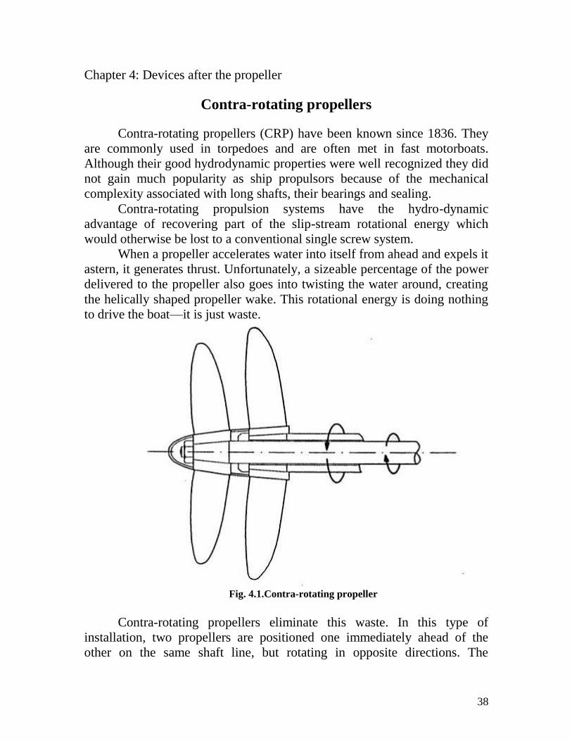
Fig. 4.1.Contra-rotating propeller
Contra-rotating propellers eliminate this waste. In this type of
installation, two propellers are positioned one immediately ahead of the
other on the same shaft line, but rotating in opposite directions. The
39
rotational energy imparted to the water by the forward propeller is cancelled
out by the opposite rotation of the aft propeller.
Furthermore, because of the two propeller configuration,contra-
rotating propellers possess a capability for balancing the torque reaction
from the propulsor which is an important matter for torpedo and other
similar propulsion problems.
In marine applications of contra-rotating propulsion is normal for the
aftermost propeller to have a smaller diameter than the forward propeller,
and, in this way, accommodate the slipstream contraction effects.
Similarly, the blade numbers of the forward and aft propellers are usually
different.
This is because the astern propeller is working in a faster water flow
than the ahead propeller, and as a result, it must have a smaller diameter and
steeper pitch. At the same time, both propellers should be absorbing the
same horsepower—hence the additional blade on the after propeller.
Because of the large number of blades—usually seven or nine, in
total—a contra-rotating propeller system has more blade area and thus lower
blade loading than a comparable single propeller at the same horsepower.
This reduces cavitation problems, and the large number of blades greatly
diminishes vibration.
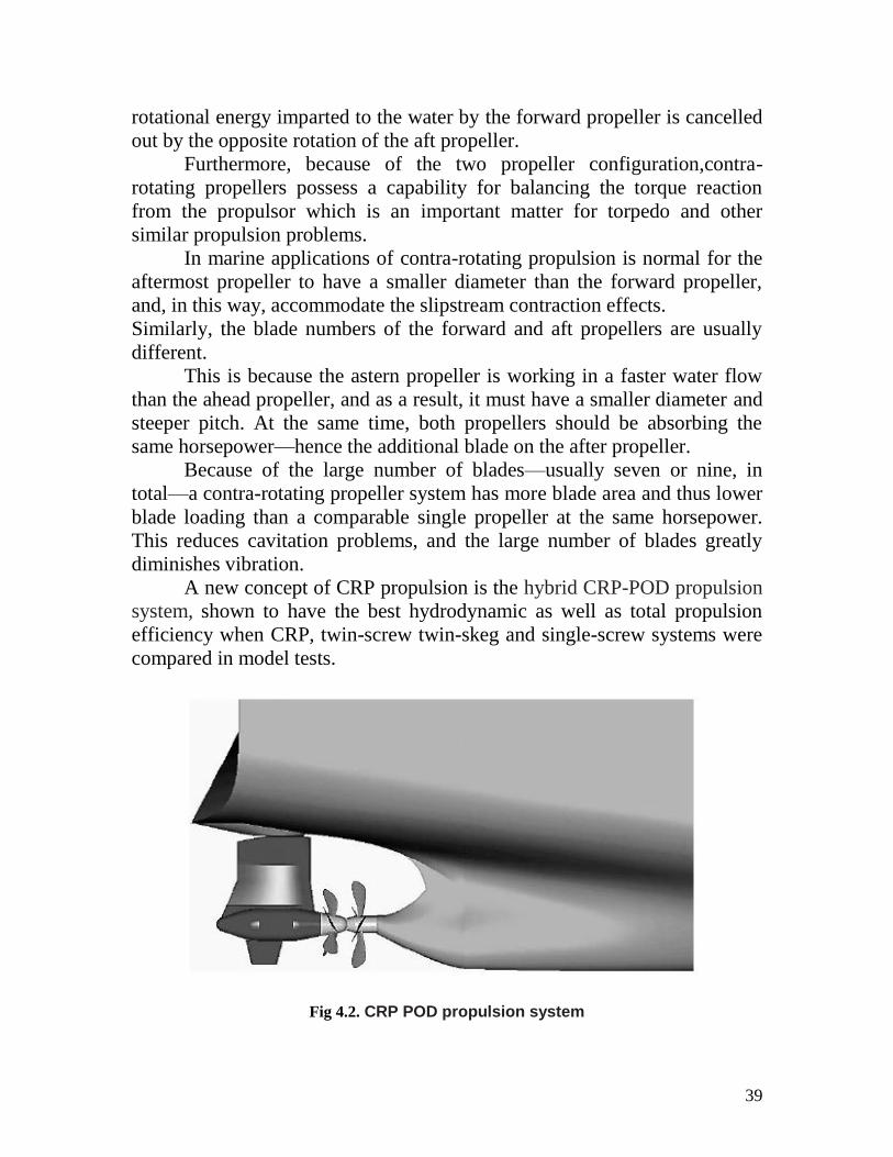
A new concept of CRP propulsion is the hybrid CRP-POD propulsion
system, shown to have the best hydrodynamic as well as total propulsion
efficiency when CRP, twin-screw twin-skeg and single-screw systems were
compared in model tests.
Fig 4.2. CRP POD propulsion system
40
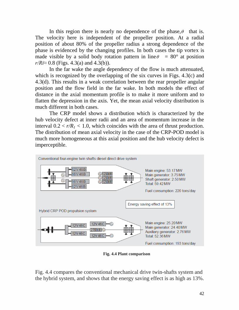
CRP has been developed by combining an electric pod propulsion unit
and conventional diesel propulsion system. With this system, energy is
saved by more than 13% as compared with the conventional twin shafts and
propellers system, contributing to a reduction of operation costs and of CO2
emission.
The CRP Azipod propulsion system consists of two contra-rotating
propellers.Located on the same axis, but without physical connection, the
pulling propeller of the Azipod unit will contra-rotate in relation to the shaft-
driven main propeller. There is no need for a conventional rudder because
the pulling Azipod unit acts as one.
The pod propulsion unit is an azimuth type one driving a propeller
directly coupled with a motor by incorporating the motor in a pod unit. This
propulsion unit is at the stern of the hull, and also the unit has a function of
rudder due to rotation. Thanks to its 360-degree free rotation, excellent
steering performance is realized in harbor and pier operations, together with
powerful propulsion.This compact system incorporating a propulsion motor
in the pod was jointly developed by European electric manufacturer and
shipyard in the early 1980s for ice breakers.
The pod propulsion unit, a revolutionary system in those days, has
been employed in more than 70 vessels, but since it is an expensive system,
it has been used mainly in cruise passenger ships so as to make
the best of its features, including excellent steering performance, vibration
and noise suppressing effect,and high flexibility of inboard layout.
As shown in Fig. 4.2, in this ship, the pod propulsion unit is located
immediately behind the coaxial line of the main propeller of one shaft, and
two propellers are arranged like one set of contra-rotating propellers. The
main propeller is a controllable pitch propeller, and is driven directly by two
sets of medium speed diesel main engines by way of reduction gears with
clutch and intermediate shaft. The pod propeller positioned behind is an
electric propulsion unit driven by an electric motor in the pod,using electric
power from the power generation plant.
As a result, two sets of propellers can be installed without any
appendages such as shaft bracket, and the resistance performance is
significantly improved as compared with the conventional twin shafts ship.
In addition,rotating the adjacent propellers in opposite directions could
realize high propulsion efficiency by reducing tangential water flow.

41
A comparison between classical CRP system and the CRP-POD can
be made if we are comparing the results of the mean axial velocity at one
diameter distance from the rear propeller plane it is clear how in the contra-
rotating propeller pod drive model the axial momentum reaches higher
values, while presenting a more uniform distribution. Near the axis, the
mean axial velocity shows a strongly marked depression, which is present in
both the CRP and the CRP-POD drive models. While for the first the
velocity drops to almost half of the propeller advance speed, VA for the last
model the velocity never falls below 1A
A
V
U,the low values of axial
momentum near the propeller axis evidence the velocity defect due to the
influence of the propeller hub, which is not producing thrust.
Fig 4.3.Distribution mean axial velocity
42
In this region there is nearly no dependence of the phase, that is.
The velocity here is independent of the propeller position. At a radial
position of about 80% of the propeller radius a strong dependence of the
phase is evidenced by the changing profiles. In both cases the tip vortex is
made visible by a solid body rotation pattern in line = 80° at position
r/Ri≈ 0.8 (Figs. 4.3(a) and 4.3(b)).
In the far wake the angle dependency of the flow is much attenuated,
which is recognized by the overlapping of the six curves in Figs. 4.3(c) and
4.3(d). This results in a weak correlation between the rear propeller angular
position and the flow field in the far wake. In both models the effect of
distance in the axial momentum profile is to make it more uniform and to
flatten the depression in the axis. Yet, the mean axial velocity distribution is
much different in both cases.
The CRP model shows a distribution which is characterized by the
hub velocity defect at inner radii and an area of momentum increase in the
interval 0.2 < r/R1 < 1.0, which coincides with the area of thrust production.
The distribution of mean axial velocity in the case of the CRP-POD model is
much more homogeneous at this axial position and the hub velocity defect is
imperceptible.
Fig. 4.4 Plant comparison
Fig. 4.4 compares the conventional mechanical drive twin-shafts system and
the hybrid system, and shows that the energy saving effect is as high as 13%.
43
Advantages
*The propeller-induced heeling moment is compensated (negligible for
larger ships).
*The slipstream from contra-rotating propellers is nearly smooth and
straight, with little twist. Such propellers are, in theory, between 5 and 20
percent more efficient than standard single propellers, but 8 to 10 percent is
a realistic practical range.
*More power can be transmitted for a given propeller radius.
*The propeller efficiency is usually increased.
* Less emissions, environmentally friendly
Particularly, for the CRP-POD hybrid system ,the advantages are:
*The energy gain is even higher, because the resistance of the appendages
(propeller shafts, brackets, skegs, rudders etc.) is absent. This significantly
decreases the ship’s resistance since the propulsor is located in the
decelerated flow region.
* Two independent propulsion systems give high redundancy
*No need for stern thrusters
*Flexible general arrangement
*Less pressure pulses on vessel hull
*Easily adjustable propulsion machinery to match required propulsion
power.
* The hybrid concept is especially attractive when the main propulsion is
very heavily loaded due to the large ship speed or power requirements of the
vessel. Adding a pod to the main propulsion will raise the
overall speed and power.
Disadvantages
* The main drawback to contra-rotating propellers is their tremendous
complexity. Not only docs this increase the cost of contra-rotating propellers
to far above that of comparable standard single propellers, but it also
increases the level of maintenance required. Further, some of the gain in
efficiency from thrust is lost to additional frictional resistance in the many
extra gears and bearings.
*The hydrodynamic gains are partially reduced by mechanical losses in
shafting.
44
* The sealing of the shafting against the ingress of water from outside is also
a major problem.
*The resistance of the pod parts (the motor housing and the strut).
Apart from their long-standing use in torpedoes, contra-rotating
propellers have been tried out in submarines, and more recently in merchant
ships.
The Grim wheel, is related to the contra-rotating propeller, but
the ‘aft’ propeller is not driven by a shaft. Unlike a contra-rotating propeller,
the Grim wheel turns in the same direction as the propeller.
45
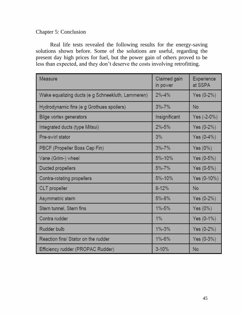
Chapter 5: Conclusion
Real life tests revealed the following results for the energy-saving
solutions shown before. Some of the solutions are useful, regarding the
present day high prices for fuel, but the power gain of others proved to be
less than expected, and they don’t deserve the costs involving retrofitting.

46
Bibliography
[1]- Marine Propellers and propulsion ,John Carlton
[2]- Hydrodynamics of Ship Propellers, John P. Breslin, Poul Andersen
[3]- Ship Design for Efficiency and Economy, Herbert Schneekluth, Volker
Bertram
[4]- Navgathi Marine Design & Constructions Pvt. Ltd.
[5]- Det Norske Veritas AS
Figures:
1.1- http://www.propellerpages.com, FAO - Food and Agriculture
Organization of the United Nations; FAO FISHERIES TECHNICAL
PAPER 383
1.2- Retrofit propulsion improvement, Wartsila
1.3- Marine Propellers and propulsion ,John Carlton
2.1- Schneekluth
2.2,2.3- Hydrodynamics of Ship Propellers, John P. Breslin, Poul Andersen
2.4- Wartsila
2.5- Year Book 2007 : Progress of Marine Engineering Technology in the
year 2006
2.6,2.7- Schneekluth, Ship Design for Efficiency and Economy, Butterworth
& Co Ltd.
3.1,3.3,- Hydrodynamics of Ship Propellers, John P. Breslin, Poul Andersen
3.2- Wikimedia Commons
3.4,3.5,3.6,3.7,3.8- http://www.roblightbody.com
4.1- Marine Propellers and propulsion ,John Carlton
4.2,4.3- New Results in Numerical and Experimental Fluid Mechanics VI
4.4,4.5- Varldssjofartens_Dag_2007_presentationer
5.1- SSPA Sweden AB