raspberry pi 遊戲機工作坊 -...
TRANSCRIPT


姓名標示 — 非商業性 — 相同方式分享
CC (Creative Commons)
姓名標示 — 你必須給予 適當表彰、提供指向本授權條款的連結,以及 指出(本作品的原始版本)是否已被變更。你可以任何合理方式為前述表彰,但不得以任何方式暗示授權人為你或你的使用方式背書。
非商業性 — 你不得將本素材進行商業目的之使用。
相同方式分享 — 若你重混、轉換本素材,或依本素材建立新素材,你必須依本素材的授權條款來散布你的貢獻物。

3
● Raspberry Pi官方經銷商
about 台灣樹莓派
http://farnell.com/raspberrypi-consumer/approved-retailers.php?region=apac&MER=MER-LM-OB-RPICC-76315

● 專注於 Raspberry Pi 應用與推廣
● 舉辦社群聚會 / 工作坊 / 讀書會 /黑客松
● Website:● https://www.raspberrypi.com.tw/
● Facebook: ● 搜尋 RaspberryPi.Taiwan● https://www.facebook.com/RaspberryPi.Taiwan
社群 x 活動

5
● COSCUP,MakerConf,PyCon講者
● 投影片
● http://www.slideshare.net/raspberrypi-tw/presentations
● 程式碼
● https://github.com/raspberrypi-tw
分享 x 教學

6
● Raspberry Pi GPIO 介紹
● 環境設定● 輸入 /輸出
● 數位 /類比● 練習與實做
本次主題

7
● 了解電子電路原理● 學習如何根據規格撰寫控制程式● 親手完成遊戲機
目標

8
● 硬體:Raspberry Pi 3
● 作業系統:2016-09-23-raspbian-jessie.img
● 為了可以使用USB轉TTL傳輸線
● 修改/boot/config.txt,新增三行
– dtoverlay=pi3-miniuart-bt
– core_freq=250
– enable_uart=1
● 修改/boot/cmdline.txt,將quiet splash的quiet移除
今日環境
刪除 quiet
新增三行

9
● $ sudo apt-get update● $ sudo apt-get install -y x11vnc python-dev python-pip libsdl1.2-dev
● $ sudo pip install spidev evdev
安裝今日所需套件 ( 已安裝 )

10
Raspberry Pi GPIO 介紹

11
● General Purpose Input Output● GPIO 是一種可用軟體控制的數位訊號
什麼是 GPIO ?
http://www.tek.com/datasheet/tps2000b-series-digital-storage-oscilloscopes-datasheet

12
● 決定是輸入還是輸出● 輸出:寫值到某根腳位● 輸入:從某根腳位讀值
● 等待中斷 (interrupt) 的發生
● 決定是正緣觸發還是負緣觸發
用軟體控制什麼 ?

13
GPIO 腳位在哪裡?
http://www.raspberrypi-spy.co.uk/
Pin1 Pin2
Pin25 Pin26
Pin3 Pin4Z
Z 字型的腳位編號

14
● GPIO高電位輸出為 3.3V● GPIO容忍輸入電位為 3.3V● 單一 Pin輸出電流為 3mA-16mA● 全部 Pin輸出總和小於 50mA● GPIO輸入低電位為小於 0.8V,高電位為大於 1.3V
幾個 GPIO 的數字
https://www.scribd.com/doc/101830961/GPIO-Pads-Control2
15
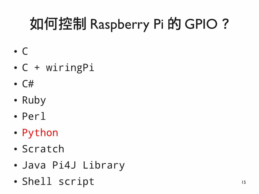
● C● C + wiringPi● C#● Ruby● Perl● Python● Scratch● Java Pi4J Library● Shell script
如何控制 Raspberry Pi 的 GPIO ?

16
● Python + RPi.GPIO = 70 kHz● C + BCM 2835 = 5.4 MHz● Ruby + wiringpi bindings = 21 kHz
GPIO Benchmark
http://www.tek.com/datasheet/tps2000b-series-digital-storage-oscilloscopes-datasheet

17
Python + GPIO

18
● 變數 ,物件 , 型別 ,註解
● 模組● 縮排● 迴圈● 條件判斷● 函式
Python五分鐘速成

19
● 動態型別 (dynamic typing)
# 這是註解
i = 3 # 變數 i指到數字物件 3
i = [1, 2, 3, 4, 5] # 變數 i指到串列物件
print i[2] # 印出串列中第三個元素
i = “abcde” # 變數 i指到字串物件
print i[2] # 印出字串中第三個元素
變數 , 物件 , 型別 , 註解

20
# import MODULE
import RPi.GPIO
# import MODULE as ALIAS
import RPi.GPIO as GPIO
模組

21
● 用縮排取代大括號● 程式碼的區塊是用縮排分隔
● 不使用 tab, 使用空白鍵
● 常見縮排為 4 個空白鍵
縮排

22
● 自動迭代 (iterator)
for i in xrange(start, stop[, step]):
process
for i in xrange(0, 11, 5):
process
迴圈

23
if condition_1:
process_1
elif condition_2:
process_2
else:
process_3
process_4
條件判斷

24
def function_name():
process
def function_name(param_name):
process
def function_name(param_name = 3):
process
函式

25
電子入門套件
● 紅/黃/綠LED x2
● 1/4W電阻,1Kx5,2Kx5
● 830洞大型麵包板 x1
● 按鍵 x4
● 蜂鳴器 x2
● 人體紅外線感測器(PIR) x1
● 傾斜開關 x1
● MCP3008 ADC IC x1
● 光敏電阻 x1
● XY搖桿 x1
● HC-SR04超音波距離感測器
● 10K可變電阻
● 20pin公對公 / 公對母/母對母排線 x1

26
本套件相容於全系列 Raspberry Pi
購買 :https://www.raspberrypi.com.tw/2557/

27
數位輸出

28
實驗1:硬體的 Hello World
目的 :從硬體到軟體的思維

29
● 發光二極體● 單向導通● 省電
LED
http://upload.wikimedia.org/wikipedia/commons/c/c8/5mm_Red_LED.jpg
長腳接正極 Vcc短腳接負極GND

30
● 電路組成元件 :電源、導線、負載
● 閉路 :當三者形成一完整路徑 ,有電流經過電路
● 歐姆定律 :導體兩端的電壓與通過的電流成正比
● V = I x R
電路一分鐘速成
I
I
V RV R
I
https://zh.wikipedia.org/wiki/电路
31
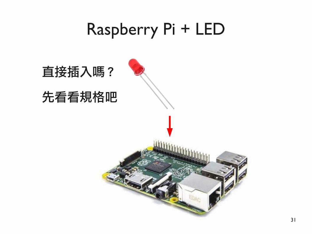
Raspberry Pi + LED
直接插入嗎 ?
先看看規格吧

32
● VF:順向電壓
● IF: 在順向電壓下的安全電流
LED 的特性
https://learn.adafruit.com/all-about-leds/forward-voltage-and-kvl

33
● 在順向電壓下一般的 LED能承受的安全電流是 20mA● 由於順向電壓 (Typical)為 1.85V ● Raspberry Pi 的 GPIO腳位能提供 3.3V● 計算公式:電阻 =電壓 /電流
R =V/I
R =(3.3-1.85)/0.02=72.5歐姆● 表示最小要接 72.5歐姆的電阻 ,才能避免 LED燒毀
如何解讀?

34
電阻阻值計算
www.digikey.tw/tw/zht/mkt/5-band-resistors.html
四環:右側為金或銀
五環:前四環很靠近1K=棕黑黑棕 (棕 )2K=紅黑黑棕 (棕 )

35
要接哪一個腳位?

36
要接哪一個腳位?
目標 :一隻腳接地, 一隻腳給電

37
線路圖LED RPi長腳 (RED) Pin12 (GPIO18)短腳 (BLACK) Pin6 (Ground)
1k電阻:棕黑黑棕 (棕 )

38
線路圖LED RPi長腳 (RED) Pin12 (GPIO18)短腳 (BLACK) Pin6 (Ground)
1k電阻:棕黑黑棕 (棕 )

39
麵包板的種類
https://goo.gl/JipVgH

40
麵包板的使用
http://bugworkshop.blogspot.tw/2012/12/diy-breadboard.html
1. 藍色和綠色兩塊不通2. 藍色水平相通3. 紅色垂直相通 麵包板的內部結構

41
麵包板的使用
http://bugworkshop.blogspot.tw/2012/12/diy-breadboard.html
麵包板的內部結構
我有相連
我也有相連

42
使用麵包板方便多了
1k 電阻

43
● 試試看這樣接
不會亮嗎? 因為你沒寫程式阿

44
各腳位的意義
https://goo.gl/f2rPpN

45
開始用 Python 控制 GPIO吧

46
● 載入模組 (Import module) ● 選擇編號系統 (Define pin numbering)● 定義腳位 (Setup up a channel)● 讀取輸入 / 寫入輸出 (Input/Output)● 清理 (Cleanup)
Python Code基本流程
http://code.google.com/p/raspberry-gpio-python/wiki/BasicUsage

47
#!/usr/bin/python ●
● import RPi.GPIO as GPIO # Import module
● import time ●
● GPIO.setmode(GPIO.BOARD) # Define pin numbering
● LED_PIN = 12
● GPIO.setup(LED_PIN, GPIO.OUT) # Setup up a channel●
● print "LED is on"
● GPIO.output(LED_PIN, GPIO.HIGH) # Input/Output status
● time.sleep(3)
●
● GPIO.cleanup() # Cleanup
一個實際的範例

48
DEMOled_on.py

49
使用:nano <檔名,例如led_on.py>
離開:Ctrl + x
> 令存新檔:y
> 不存離開:n
> 離開:Ctrl + c
nano 編輯器使用

50
● $ cd < 目錄 > # 跳到 <目錄 >● $ cd .. # 回上一層● $ cd ~ # 回 <家目錄 >
● $ pwd # 查看目前工作目錄
● $ ls # 列出檔案與目錄
● $ sudo reboot # 重開機
你必須知道的 Linux 指令

51
$ cd ~
$ git clone https://github.com/raspberrypi-tw/gpio-game-console.git
$ cd ~/gpio-game-console
$ cd 01-led_on
$ python led_on.py
讀寫 GPIO 會存取 /dev/mem, 需 root 權限(2015-09-24 以後的 image 可以用一般使用者身份執行 )
執行方式

52
● Wiki● http://sourceforge.net/p/raspberry-gpio-python/wiki/Home/
● Code● http://sourceforge.net/p/raspberry-gpio-python/code/ci/default/tree/
● Reference detail● http://elinux.org/RPi_Low-level_peripherals● http://elinux.org/RPi_BCM2835_GPIOs● http://www.raspberrypi.org/wp-content/uploads/2012/02/BCM2835-ARM-Peripherals.pdf
更多 RPi.GPIO 的使用方法

53
實驗2:控制 LED閃爍
目的 :熟悉 Python語法

54
一樣的線路圖LED RPi長腳 (RED) Pin12 (GPIO18)短腳 (BLACK) Pin6 (Ground)
1k 電阻

55
GPIO.setmode(GPIO.BOARD)
● LED_PIN = 12
● GPIO.setup(LED_PIN, GPIO.OUT)
●
● while True:
● print "LED is on"
● GPIO.output(LED_PIN, GPIO.HIGH)
● time.sleep(1)
● print "LED is off"
● GPIO.output(LED_PIN, GPIO.LOW)
● time.sleep(1)
●
● GPIO.cleanup()
永不停止的 while 迴圈-按Ctrl+c跳出迴圈

56
DEMOled_blink_warning.py
$ cd ~/gpio-game-console
$ cd 02_1-led_blink_warning
$ python led_blink_warning.py

57
RuntimeWarning: This channel is already in use, continuing anyway. Use GPIO.setwarnings(False) to disable warnings.

58
為什麼出現Warning ?

59
● 在正常情況下執行完畢結束● 遇到錯誤跳出
● 受到中斷停止 (收到終止訊號 ,例如 Ctrl+c)
程式何時會結束 ?

60
try:
● while True:
print "LED is on"
● GPIO.output(LED_PIN, GPIO.HIGH)
● time.sleep(1)
print "LED is off"
● GPIO.output(LED_PIN, GPIO.LOW)
● time.sleep(1)
● except KeyboardInterrupt:
● print "Exception: KeyboardInterrupt"
● finally:
● GPIO.cleanup()
接住例外

61
DEMOled_blink.py
$ cd ~/gpio-game-console
$ cd 02_2-led_blink
$ python led_blink.py

62
實驗3:用 LED 做交通號誌
目的:結構化程式設計

63
● 紅 ,黃 ,綠燈依序亮燈
● 紅燈亮 4秒 ,黃燈亮 2秒 ,綠燈亮 4秒
設計一個紅綠燈
http://www.clipartbest.com/traffic-light-photo

64
線路圖

65
DEMOtraffic_light_nonstructure.py
$ cd ~/gpio-game-console
$ cd 03_1-traffic_light_nonstructure
$ python traffic_light_nonstructure.py

66
def TrafficLight(pin, duration):
GPIO.output(pin, GPIO.HIGH)
time.sleep(duration)
GPIO.output(pin, GPIO.LOW)
try :
while True:
TrafficLight(RED_PIN, 4);
TrafficLight(YEL_PIN, 2);
TrafficLight(GRN_PIN, 4);
finally:
GPIO.cleanup()
把亮燈拿到外面

67
DEMOtraffic_light.py
$ cd ~/gpio-game-console
$ cd 03_2-traffic_light
$ python traffic_light.py

68
數位輸入

69
實驗4:讀取按鍵輸入
目的 :了解硬體和軟體的差異

70
● 開關:按鍵式 ,滑動式 ,傾斜式 ...
按鍵 Button / 開關 Switch
http://nicegear.co.nz/

71
● 常開 (normally open, N.O.)● 常閉 (normally close, N.C.)
按鍵 Button / 開關 Switch
http://www.engineersgarage.com/sites/default/files/imagecache/Original/wysiwyg_imageupload/4214/Switch-2_0.jpg

72
按鍵的內部結構
http://www.ladyada.net/learn/arduino/lesson5.html
● 按下前
● 長邊相連 (1&2,3&4)● 短邊不相連
● 按下後● 四點都通
1 2
3 4

73
簡單的按鍵接法
BUTTON RPi腳 1 Pin6 (Ground)腳 3 Pin11 (GPIO17)

74
● Input空接會讀到雜訊
問題在哪裡?
按鍵按下前未導通,讀到??按鍵按下後,讀到低電位

75
更好的按鍵接法 (上拉電阻 )
http://geekgurldiaries.blogspot.tw/2012/12/part-2.html

76
線路圖BUTTON RPi腳 1 Pin6 (Ground)腳 3 Pin11 (GPIO17) Pin1 (3.3V)
1k 電阻

77
BTN_PIN = 11
GPIO.setup(BTN_PIN, GPIO.IN)
previousStatus = None
try:
while True:
input = GPIO.input(BTN_PIN)
if input == GPIO.LOW and previousStatus == GPIO.HIGH:
print "Button pressed"
previousStatus = input
except KeyboardInterrupt:
print "Exception: KeyboardInterrupt"
finally:
GPIO.cleanup()
判斷條件 :這次低 && 上次高

78
DEMOpush_button_poll.py
$ cd ~/gpio-game-console
$ cd 04_1-push_button_poll
$ python push_button_poll.py

79
按一次出現兩次?這樣子對不對啊?

80
● 機械式開關在切換過程中會有訊號彈跳現象 (雜訊 )
開關訊號的彈跳問題 (bounce)
http://120.101.72.1/Onechip/PPT/ 實習單元三 .ppt
理想訊號輸出
實際輸出訊號

81
● 硬體方法 : 以 RC 電路或正回授的比較器電路解決
● 軟體方法 :調整觸發的延遲時間
● 不同的按鍵會有不同的延遲時間
解決彈跳問題 (de-bounce)
10ms - 20ms

82
GPIO.setup(BTN_PIN, GPIO.IN)
previousStatus = None
previousTime = time.time()
currentTime = None
try:
while True:
input = GPIO.input(BTN_PIN)
currentTime = time.time()
if input == GPIO.LOW and \
previousStatus == GPIO.HIGH and \
(currentTime - previousTime) > 0.2:
previousTime = currentTime
print "Button pressed”
previousStatus = input
不反應在延遲時間內的觸發

83
DEMOpush_button_debounce.py
$ cd ~/gpio-game-console
$ cd 04_2-push_button_debounce
$ python push_button_debounce.py

84
● 先以背景方式執行單一程式 (加上 &)● $ python push_button_debounce.py &
● 再看整體系統使用狀況
● $ top -c
如何看系統效能?
PID

85
但是這個程式的 CPU 用量挺大的
● 跑個按鍵偵測程式 CPU 使用率達 100%
● 停止該程序 (PID 為 1427)● $ kill -9 1427

86
● 輪詢 (polling)● SoC每隔一段時間檢查週邊硬體的資料
● 中斷 (interrupt)● 當週邊硬體的狀態改變時 ,對 SoC 發出中斷要求
輪詢與中斷

87
● 建立回呼函數
● def mycallback()
● 綁定事件和回呼函數
● add_event_detect(gpio, # 對象
edge, # 觸發條件
callback,# 回呼函數
bouncetime)● 多個事件可以綁定同樣的回呼函數
中斷的程式寫法
source/py_gpio.c

88
BTN_PIN = 11
GPIO.setup(BTN_PIN, GPIO.IN)
def mycallback(channel):
print("Button pressed")
try:
GPIO.add_event_detect(BTN_PIN, \
GPIO.FALLING, \
callback=mycallback, \
bouncetime=200)
while True:
time.sleep(10)
finally:
GPIO.cleanup()
即使在 sleep狀態下也可立即回應

89
DEMOpush_button_interrupt.py
$ cd ~/gpio-game-console
$ cd 04_3-push_button_interrupt
$ python push_button_interrupt.py

90
● 需要硬體或軟體(作業系統)的支援
● RPi.GPIO在版本0.5.0a有了中斷功能
● 加上add_event_detect()等機制
● RPi.GPIO以建立多執行緒方式實現中斷
● 程式開始執行時, 主執行序運行
● 當加入事件後,以epoll_create建立新的fd● 當事件觸發時,第二個執行序和主執行序溝通(回呼)● 程式碼可參考source/event_gpio.c
中斷的意義
source/py_gpio.c

91
簡單的按鍵接法沒有錯 , 但是 ...

92
GPIO.setup(BTN_PIN, GPIO.IN, pull_up_down=GPIO.PUD_UP)
def mycallback(channel):
print("Button pressed")
try:
GPIO.add_event_detect(BTN_PIN, \
GPIO.FALLING, \
callback=mycallback, \
bouncetime=WAIT_TIME)
while True:
time.sleep(10)
finally:
GPIO.cleanup()
要搭配內建的上拉電阻 (50k)

93
DEMOpush_button_internal_pull_up.py
$ cd ~/gpio-game-console
$ cd 04_4-push_button_internal_pull_up
$ python push_button_internal_pull_up.py

94
實驗 5:傾斜開關
目的 :認識不同的硬體

95
傾斜開關 Tilt Switch

96
線路圖SWITCH RPi第一腳 (RED) Pin11 (GPIO17)第二腳 (BLACK) Pin6 (Ground)

97
DEMOtilt_switch.py
$ cd ~/gpio-game-console
$ cd 05-tilt_switch
$ python tilt_switch.py
使用內建的上拉電阻

98
實驗 6:蜂鳴器樂器
目的 :聲音輸出

99
● 發聲原理 :聲音是由振動產生 ,其頻率稱為音頻
● 蜂鳴器發聲原理 :電流 (6)通過電磁線圈 (3)產生磁場來驅動振動膜 (11)
● 人耳可聽到 20Hz - 20KHz
原理
http://www.itianer.com/diancishifengmingqigouzaoyuyuanlijieshao.html

100
● 自激 (有源 ):只能發出同頻率的聲音
● 黑膠封裝 ,高低腳
● 他激 (無源 ): 需從外部輸入震盪方波發聲
● 綠色電路板 ,兩腳同長
● 腳位有正負之分 (看底板 )
蜂鳴器 Buzzer
http://www.buzzer-speaker.com/manufacturer/piezo%20buzzer.htm
自激式 他激式

101
線路圖BUZZER RPi+(RED) Pin12 (GPIO18)- (BLACK) Pin6 (Ground)

102
def buzz(pitch, duration) :
period = 1.0 / pitch
half_period = period / 2
cycles = int(duration * pitch)
for i in xrange(cycles) :
GPIO.output(buzzer_pin, GPIO.HIGH)
time.sleep(half_period)
GPIO.output(buzzer_pin, GPIO.LOW)
time.sleep(half_period)
while True :
pitch_s = raw_input("Enter Pitch (200 to 2000): ")
duration_s = raw_input("Enter Duration (seconde): ")
buzz(float(pitch_s), float(duration_s))
可發出不同頻率聲音

103
DEMObuzzer.py
$ cd ~/gpio-game-console
$ cd 06_1-buzzer
$ python buzzer.py

104
●
● 標準 88鍵鋼琴 ,每個音的頻率 :● 每段音階分為 12 個半音
● 每個音的頻率是前一個的 1.05946倍 ( )
鋼琴模擬
1
2
3
4
5
6
7
0 8
http://en.wikipedia.org/wiki/Piano_key_frequencies
122

105
● 標準88鍵鋼琴 ,以第 49鍵A4為基準 (440Hz)● 各半音頻率如下:
● C5 (52th, DO): 523Hz● D5 (54th, RE): 587Hz● E5 (56th, ME): 659Hz● F5 (57th, FA): 698Hz● G5 (59th, SO): 784Hz● A5 (61th, LA): 880Hz● B5 (63th, SI): 988Hz
鋼琴頻率
http://en.wikipedia.org/wiki/Piano_key_frequencies

106
線路圖RPiPin7 BuzzerPin11 DoPin12 RePin13 MePin15 FaPin16 SoPin18 LaPin22 Si

107
DEMOpaino_buzzer.py
$ cd ~/gpio-game-console
$ cd 06_2-paino_buzzer
$ python paino_buzzer.py

108
實驗 7:人體紅外線感測器
目的 :常見感測器使用

109
Pyroelectric ("Passive") InfraRed SensorPIR 人體紅外線感測器
http://www.raspberrypi-spy.co.uk/2013/01/cheap-pir-sensors-and-the-raspberry-pi-part-1/

110
使用示意圖
http://www.ladyada.net/learn/sensors/pir.html

111
應用範例
http://www.ladyada.net/learn/sensors/pir.htmlhttp://totherails.blogspot.tw/2011/09/halloween-preparations.html

112
元件說明
http://www.ladyada.net/learn/sensors/pir.html

113
● 輸入電壓 :DC 3.3V - 24V ● 輸出電壓 :3.3V( 可直接接上 Raspberry Pi)● 延遲時間 (Tx):2.45秒 – 248秒
● 感應之後輸出維持的時間● 封鎖時間 (Ti):2.4 秒
● 感應輸出結束之後 ,再次觸發必須等待的時間
● 感應角度 :110度 x 70度● 感應距離 :3米 - 7 米
瞭解規格

114
● 感測距離設定
● 順時針 :最高為 7米● 逆時針 :最小為 3米
● 延遲時間設定 (Tx)● 順時針 :最長為 248秒● 逆時針 :最短為 2.45秒
● 實際可調整時間要看 R10,C6,R9,C7而定
感測距離 /延遲時間設定
感測距離設定 延遲時間設定

115
● 可重複觸發模式 (H)
● 不可重複觸發模式 (L)
觸發模式
H: 可重複觸發L: 不可重複觸發 (預設 )
感應 & 輸出
感應 & 等待 & 輸出

116
線路圖
Pin26

117
PIR_PIN = 26
GPIO.setup(BTN_PIN, GPIO.IN, pull_up_down=GPIO.PUD_DOWN)
def mycallback(channel):
print "Motion detected"
try:
GPIO.add_event_detect(PIR_PIN, GPIO.RISING, \
callback=mycallback, \
bouncetime=200)
while True:
time.sleep(1)
finally:
GPIO.cleanup()
再一次使用 interrupt 模式

118
DEMOpir.py
$ cd ~/gpio-game-console
$ cd 07_1-pir
$ python pir.py
觸發才拉高電位 ,因此用內建的下拉電阻

119
加上警示的LED燈吧

120
線路圖
1k 電阻
Pin26

121
DEMOpeople_alarm_system.py
$ cd ~/gpio-game-console
$ cd 07_2-people_alarm_system
$ python people_alarm_system.py

122
LED_PIN = 12
PIR_PIN = 26
GPIO.setup(PIR_PIN, GPIO.IN, pull_up_down=GPIO.PUD_DOWN)
GPIO.setup(LED_PIN, GPIO.OUT)
def mycallback(channel):
print "Motion detected"
for i in xrange(3) :
GPIO.output(LED_PIN, GPIO.HIGH)
time.sleep(0.5)
GPIO.output(LED_PIN, GPIO.LOW)
time.sleep(0.5)
try:
GPIO.add_event_detect(PIR_PIN, GPIO.RISING, callback=mycallback, bouncetime=200)
while True:
time.sleep(1)
偵測到人 , 燈閃 3 次

123
實驗 8:超音波距離感測器
目的:根據規格撰寫程式

124
● 聲音在 20°C (68°F) 的速度是 343公尺 /秒● 溫度每增加 1°,速度增加 0.6公尺/秒
測距離原理
http://en.wikipedia.org/wiki/Speed_of_soundhttps://www.modmypi.com/blog/hc-sr04-ultrasonic-range-sensor-on-the-raspberry-pi

125
● 內建發射(40kHz)與接收電路
● 根據發射與接收的時間差計算距離
● 特殊功能:US-020(長距離)、US-100(溫度補償)
HC-SR04超音波距離感測器
http://coopermaa2nd.blogspot.tw/2012/09/hc-sr04.html

126
● 避障 ,測距● 物體移動感測● 地鐵感測器
應用
http://letsmakerobots.com/robot/project/rock-crawlerhttps://www.dropbox.com/s/x0qdaq86rkc0zyv/MakerConf.pdf

127
地鐵感測器
http://makezine.com/magazine/ultrasonic-train-detector-in-stockholm-subway/

128
地鐵感測器
http://makezine.com/magazine/ultrasonic-train-detector-in-stockholm-subway/

129
● 規格與時序圖
HC-SR04
http://coopermaa2nd.blogspot.tw/2012/09/hc-sr04.html
建議測量間隔 >60ms

130
● TRIG腳位收到高電位 (3.3V)後發送超聲波
● ECHO腳位維持低電位 (0V),收到回應後拉到高電位 (5V)
● Raspberry Pi腳位的容忍電位為 3.3V
=> 將 ECHO腳位的 5V降壓為 3.3V左右
分壓電路計算
https://www.modmypi.com/blog/hc-sr04-ultrasonic-range-sensor-on-the-raspberry-pi=> R1=1K, R2取 2K

131
注意 1K, 2K 電阻
ULTRASONIC RPiVcc(RED) Pin2 (5V)Trig(YELLOW) Pin16 (GPIO23)Echo(PURPLE) Pin18 (GPIO24)Grnd(BLACK) Pin6 (Ground)
1k:棕黑黑棕
2k:棕黑黑棕
VccGnd Echo Trig

132
v = 343 # (331 + 0.6*20)
def measure() :
GPIO.output(TRIGGER_PIN, GPIO.HIGH)
time.sleep(0.00001) # 10uS
GPIO.output(TRIGGER_PIN, GPIO.LOW)
pulse_start = None
pulse_end = None
while GPIO.input(ECHO_PIN) == GPIO.LOW:
pulse_start = time.time()
while GPIO.input(ECHO_PIN) == GPIO.HIGH:
pulse_end = time.time()
t = pulse_end - pulse_start
d = t * v
d = d/2
return d*100
測量距離

133
DEMOhc_sr04_measure_distance.py
$ cd ~/gpio-game-console
$ cd 08-hc_sr04_measure_distance
$ python hc_sr04_measure_distance.py

134
實驗 9:呼吸燈
目的 :瞭解訊號模擬

135
● 數位 :0 與 1的訊號
● 類比 :連續的訊號
數位與類比
http://www.bitscope.com/software/blog/DJ/?p=DJ19A
136
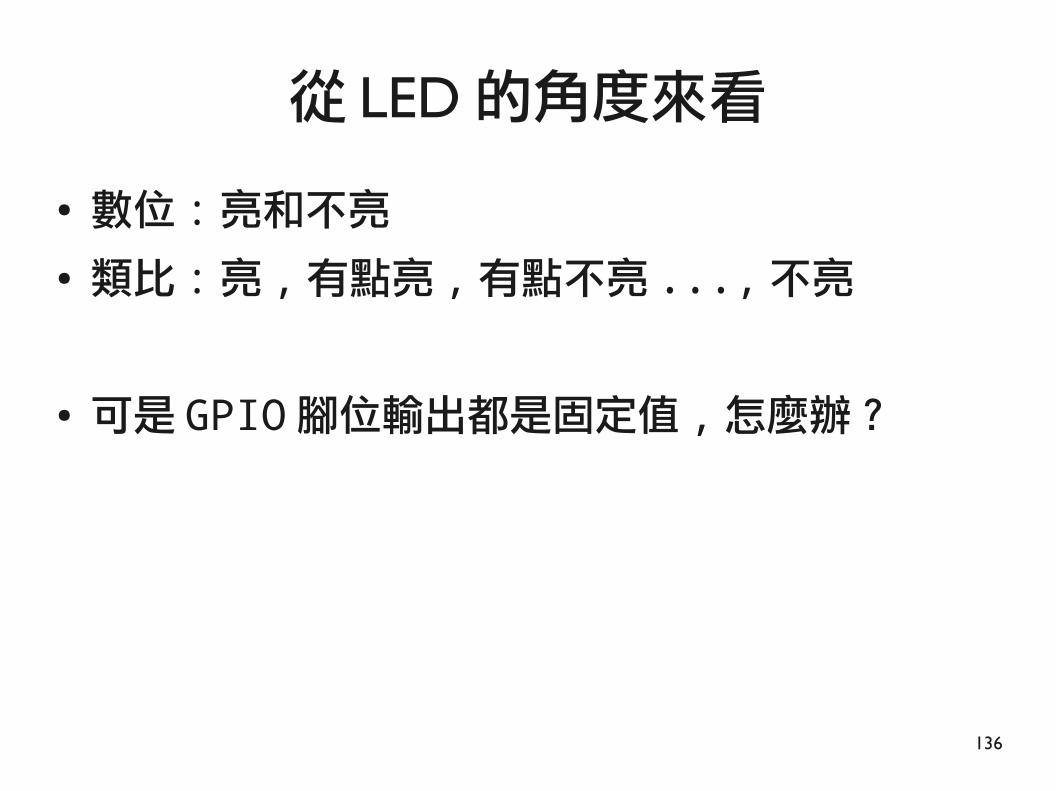
● 數位 :亮和不亮
● 類比 :亮 ,有點亮 ,有點不亮 ...,不亮
● 可是 GPIO腳位輸出都是固定值 ,怎麼辦?
從 LED 的角度來看

137
● 旋轉式 ,滑動式
● 線性關係 (B 型 ),對數關係 (A型 )● 常見規格 :0 -10k Ohm( 線性 )
可變電阻 Potentiometer(VR)
https://en.wikipedia.org/wiki/Potentiometer
接高電位
接低電位
滑動接點 (可變輸出 )

138
利用可變電阻改變 LDE亮度

139
有不使用額外硬體的方法嗎?

140
● 是將類比信號轉為脈波的一種技術
● 頻率不變 + 改變工作週期 , 使整體平均電壓值改變
● 改變工作週期 (duty cycle)= 改變平均電壓
脈寬調變 (Pulse-Width Modulation)
http://wiki.csie.ncku.edu.tw/embedded/PWM

141
● 輸出總功率 =脈衝寬度 (時間 )x 高電位值
公式計算
http://www.protostack.com/blog/2011/06/atmega168a-pulse-width-modulation-pwm/

142
● To create a PWM instance:
● p = GPIO.PWM(channel, frequency)
● To start PWM:
● p.start(dc) # dc is the duty cycle
● To change the duty cycle:
● p.ChangeDutyCycle(dc) # where 0.0 <= dc <= 100.0
● To stop PWM:
● p.stop()
GPIO.PWM()
http://sourceforge.net/p/raspberry-gpio-python/wiki/PWM/

143
線路圖LED RPi長腳 (RED) Pin12 (GPIO18)短腳 (BLACK) Pin6 (Ground)
1k 電阻

144
LED_PIN = 12
● GPIO.setup(LED_PIN, GPIO.OUT)
pwm_led = GPIO.PWM(LED_PIN, 100)
● pwm_led.start(100)
●
● try:
● while True:
● duty_s = raw_input("Enter Brightness (0 to 100):")
● duty = int(duty_s)
●
● if duty >= 0 and duty <=100 :
● pwm_led.ChangeDutyCycle(duty)
●
● except KeyboardInterrupt:
● pwm_led.stop()
● GPIO.cleanup()
互動式的調光

145
DEMOadjust_led_bright.py
$ cd ~/gpio-game-console
$ cd 09_1-adjust_led_bright
$ python adjust_led_bright.py

146
LED_PIN = 12
GPIO.setup(LED_PIN, GPIO.OUT)
pwm_led = GPIO.PWM(LED_PIN, 100)
pwm_led.start(0)
while True:
for dc in xrange(0, 101, 5):
pwm_led.ChangeDutyCycle(dc)
time.sleep(0.1)
time.sleep(0.5)
for dc in xrange(100, -1, -5):
pwm_led.ChangeDutyCycle(dc)
time.sleep(0.1)
time.sleep(0.5)
呼吸燈就是漸明漸亮

147
● 兩者差異
● Software PWM是透過kernel做duty cycle的調整
● Hardware PWM是SoC透過DMA做調整● 使用時機
● 不需要精準時用Software PWM,例如LED調光● 需要低延遲時用Hardware PWM,例如伺服馬達
● Hardware PWM GPIO只有實體腳位Pin 12和Pin 33(Model B+以後)支援
● 目前已經內建pigpiod提供Hardware PWM函式呼叫
Software PWM vs. Hardware PWM

148
DEMOpwm_led.py
$ cd ~/gpio-game-console
$ cd 09_2-pwm_led
$ python pwm_led.py

149
實驗10:光敏電阻
目的 :類比訊號的讀取

150
● 硫化鎘 (CdS) 或光敏電阻器 (LDR), 阻抗隨光落在表面的總量而轉變
● 光越強阻值越小 ,反之光越弱阻值則越大
● 應用 :光控開關 ,電子玩具 ,工業控制
光敏電阻
http://www2.nkfust.edu.tw/~jlkuo2/31/a6.htm

151
● Raspberry Pi沒有硬體的類比數位轉換器 (ADC)
類比訊號轉換為數位訊號
http://www.planetoftunes.com/digital-audio/how-do-analogue-to-digital-converters-work.html
IN ADC OUT
此ADC 的解析度為 4bits從 0000 到 1111(看 Y軸 )

152
● 類比數位轉換器 (Analog to Digital Converter)● 8通道 ,10 bits解析度
● SPI協議
利用 MCP3008

153
● 主從式架構 , 可一對多
● 四線同步序列資料協定
● SS:週邊選擇線 (CE)● SCK:序列時脈線 (SCLK)● MOSI: 主往從送
● MISO: 從往主送
Serial Peripheral Interface(SPI)
https://en.wikipedia.org/wiki/Serial_Peripheral_Interface_Bus

154
● $ sudo raspi-config
啟用 Raspberry Pi 的 SPI

155
● $ sudo raspi-config
啟用 Raspberry Pi 的 SPI

156
● $ sudo raspi-config
啟用 Raspberry Pi 的 SPI

157
● 測試確認SPI模組已載入
● $ ls /dev/spi*
● 安裝必要套件(如果前面已裝過,就不需再裝)● $ sudo apt-get update● $ sudo apt-get install -y python-dev python-pip
● $ sudo pip install spidev
SPI 使用前的確認

158
線路圖MCP3008 RPiCLK Pin23 (SCLK)Din Pin19 (MOSI)Dout Pin21 (MISO)CS Pin24 (CE0)

159
● SPI會用到的腳位是 MOSI,MISO,SCLK和 CE0/CE1
再看一次腳位定義

160
spi = spidev.SpiDev()
spi.open(0,0) # (0,0)表示接到CE0腳位,對應到/dev/spidev0.0裝置檔
def ReadChannel(channel):
adc = spi.xfer2([1,(8+channel)<<4,0])
data = ((adc[1]&3) << 8) + adc[2]
return data
def ConvertVolts(data,places):
volts = (data * 3.3) / float(1023)
volts = round(volts,places)
return volts
light_channel = 0
delay = 1
while True:
light_level = ReadChannel(light_channel)
light_volts = ConvertVolts(light_level, 2)
print("Light:{} ({}V)".format(light_level,light_volts))
time.sleep(delay)

161
程式要照硬體規格撰寫

162
● input一次送三個bytes● # byte 1: the start bit (always 0x01)● # byte 2: configure bits● # byte 3: don't care
● spi.xfer2([1,(8+channel)<<4,0])
● Ch0 = 1000 0000● Ch1 = 1001 0000
了解 spi.xfer2() 的意義
0x01 don't careCh0/Ch1

163http://wolfpaulus.com/

164http://wolfpaulus.com/
Output也是一次回傳三個 bytes因為是 10bits 解析度 , 所以我們只取最後有用的 10bits

165
DEMOphotoresistor.py
$ cd ~/gpio-game-console
$ cd 10-photoresistor
$ python photoresistor.py

166
實驗13:模擬器
目的 :系統整合

167
遊戲機 = 硬體 + 遊戲
http://www.emulatorworld.com/

168
● 模擬不同的硬體架構● 常見的模擬器:
● MAME (AdvanceMAME)● Nintendo Entertainment System (RetroArch)
● Super Nintendo Entertainment System (PiSNES)
● PC / x86 (rpix86)
Video Game System Emulators
https://en.wikipedia.org/wiki/List_of_video_game_emulators

169
● 模擬大台電動玩具
MAME(Multiple Arcade Machine Emulator)
http://www.williamsamusements.co.uk/mame.html

170
● RFB協定 +螢幕畫面分享及遠端操作軟體
● 與作業系統無關 , 可跨平台使用
● Client/Server架構
用 Virtual Network Computing看畫面

171
● 第一種:鏡像桌面 (x11vnc)● 連接到真實的 x11 display
● 第二種:虛擬桌面 (xvnc)● 連接到 X server
不同的 VNC

172
鏡像桌面 (x11vnc)

173
● $ sudo apt-get install x11vnc● $ x11vnc
● 更多設定
● x11vnc 不斷線
– $ x11vnc -forever
● 設定 x11vnc 連線視窗大小
– $ x11vnc -geometry 寬度 x高度
在 Pi 安裝和執行 x11vnc Server
英文字母小寫 x

174

175

176
● Windows:
● 下載UltraVNC (可以只安裝Viewer)
– http://www.uvnc.com/downloads/
x11vnc Client 安裝
Port 和 x11vnc 相同

177

178
● 下載編譯好的binary(已經下載好了)
● $ cd ~● $ wget http://goo.gl/mN5zhS -O advmame● $ chmod 755 advmame● $ ./advmame
● 2.下載rom(還沒下載)
● $ cd /home/pi/.advance/rom● Google搜尋AdvanceMAME suprmrio rom
● 3. 執行模擬器
● $ cd /home/pi● $ ./advmame suprmrio
在 x11vnc下執行 AdvanceMAME

179
● 搜尋MAME● http://www.emuparadise.me/
● 中英文對照● http://bbs.duowan.com/thread-41350071-1-1.html
● 經典遊戲● 超級瑪莉歐● 彈珠台● 小精靈● 坦克大作戰,泡泡龍...
下載 ROM放到對應的目錄下
http://en.wikipedia.org/wiki/Nintendo_Entertainment_System

180
● 執行模擬器 , 使用 keyboard 控制
● 讀取 GPIO搖桿的值
● 讓 GPIO搖桿和 keyboard對應
● 開機就啟動按鍵與 keyboard對應程式
● 開機就啟動模擬器
遊戲機製作步驟
http://bruxy.regnet.cz/web/linux/EN/housenka-bash-game/http://www.linuxuser.co.uk/tutorials/emulate-a-bluetooth-keyboard-with-the-raspberry-pi

181
● $ cd ~● $ ./advmame suprmrio
● 按 'o' 'k'進入畫面
● 按 '5'投錢
● 按 '1'開始
● 左邊 'ctrl'是加速
● 左邊 'alt'是跳
● 按 'esc'是離開
使用模擬器

182
搖桿 (joystick)

183
● 3.3V-5V工作電壓
● 輸出形式:
● x,y軸 - 類比輸出
● z軸 - 數位輸出
XY雙軸搖桿
http://www.aliexpress.com/cheap/cheap-arduino-joystick.html
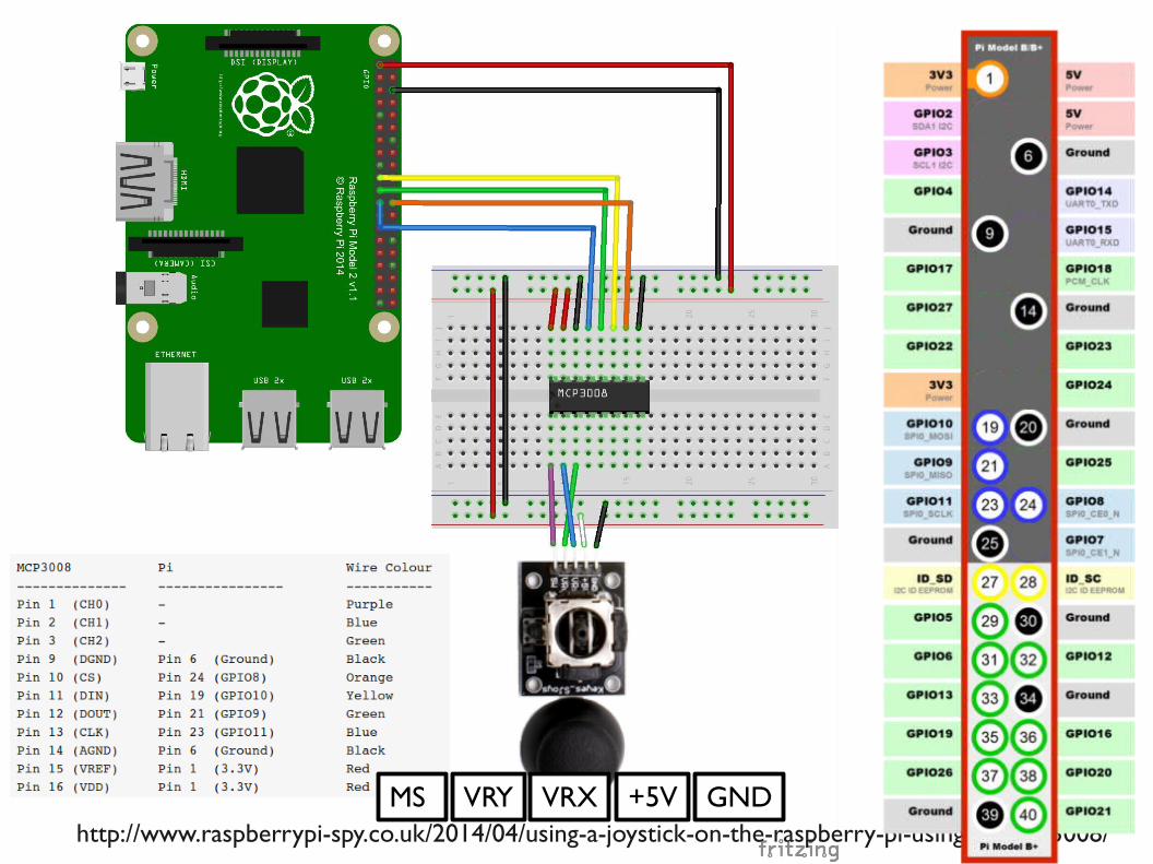
184http://www.raspberrypi-spy.co.uk/2014/04/using-a-joystick-on-the-raspberry-pi-using-an-mcp3008/
+5VMS VRY VRX GND

185
spi = spidev.SpiDev()
● spi.open(0,0)
●
● def ReadChannel(channel):
● adc = spi.xfer2([1,(8+channel)<<4,0])
● data = ((adc[1]&3) << 8) + adc[2]
● return data
●
● vrx_channel = 1
● vry_channel = 2
●
● while True:
● vrx_pos = ReadChannel(vrx_channel)
● vry_pos = ReadChannel(vry_channel)
●
● print("X : {} Y : {} ".format(vrx_pos,vry_pos))
●
● time.sleep(0.5)

186
DEMOmcp3008_joystick
$ cd ~/gpio-game-console
$ cd 11_1-mcp3008_joystick
$ python mcp3008_joystick.py

187
搖桿如何和 keyboard對應?

188
Linux 輸入與輸出的處理流程
https://en.wikipedia.org/wiki/Evdev

189
Linux Input Subsystem
http://www.linuxjournal.com/article/6396

190
● USB或 PS2 keyboard都是同一個 handler處理
● 我們可以加上 GPIO的 driver,讓 keyboard handler來接?
Linux Input Subsystem
http://www.linuxjournal.com/article/6396
USB Keyboard
PS2 Keyboard

191
除了在 kernel space 做以外,
可以在 user space 做嗎?

192
● evdev● Bindings to the Linux input handling subsystem
● python-evdev● provides bindings to the generic input event interface in Linux
● 安裝(如果前面已裝過, 就不需再裝)● $ sudo pip install evdev
python-evdev
https://pypi.python.org/pypi/evdev

193
python-evdev keyboard examplefrom evdev import UInput, ecodes as e
ui = UInput()
ui.write(e.EV_KEY, e.KEY_H, 1) # KEY_H down
ui.write(e.EV_KEY, e.KEY_H, 0) # KEY_H up
ui.write(e.EV_KEY, e.KEY_E, 1)
ui.write(e.EV_KEY, e.KEY_E, 0)
ui.write(e.EV_KEY, e.KEY_L, 1)
ui.write(e.EV_KEY, e.KEY_L, 0)
ui.write(e.EV_KEY, e.KEY_L, 1)
ui.write(e.EV_KEY, e.KEY_L, 0)
ui.write(e.EV_KEY, e.KEY_O, 1)
ui.write(e.EV_KEY, e.KEY_O, 0)
ui.syn()
● ui.close()

194
DEMOevdev_keyboard.py
$ cd ~/gpio-game-console
$ cd 11_2-evdev_keyboard
$ sudo python evdev_keyboard.py

195
看不到結果嗎?

196
開 x11vnc看

197
上下左右鍵與搖桿的對應

198
上下左右鍵與搖桿的對應
- 觀察操作搖桿與畫面輸出值的關係

199
vrx_channel = 1
while True:
vrx_pos = ReadChannel(vrx_channel)
if vrx_pos > 700 :
ui.write(e.EV_KEY, e.KEY_DOWN, 1)
ui.write(e.EV_KEY, e.KEY_UP, 0)
ui.syn()
elif vrx_pos < 200 :
ui.write(e.EV_KEY, e.KEY_DOWN, 0)
ui.write(e.EV_KEY, e.KEY_UP, 1)
ui.syn()
else :
ui.write(e.EV_KEY, e.KEY_DOWN, 0)
ui.write(e.EV_KEY, e.KEY_UP, 0)
ui.syn()
time.sleep(0.1)

200
DEMOjoystick_mapping_keyboard.py
$ cd ~/gpio-game-console
$ cd 11_3-joystick_mapping_keyboard
$ sudo python joystick_mapping_keyboard.py

201
搖桿 +按鍵的應用
MakerFaire 2014 Raspberry Jam

202
線路圖
Pin7 Pin12

203
DEMOgaming_console.py
$ cd ~/gpio-game-console
$ cd 13-gaming_console
$ sudo python gaming_console.py

204
● 第一個執行超級瑪莉 (x11vnc)
● $ cd ~● $ ./advmame suprmrio
用搖桿控制超級瑪莉- 需要開啟兩個視窗
從 x11vnc 連線後執行超級瑪莉

205
● 第二個執行搖桿按鍵對應程式(serial或ssh)
● $ cd ~/gpio-game-console/11_3-joystick_mapping_keyboard● $ sudo python joystick_mapping_keyboard.py
用搖桿控制超級瑪莉
從 serial 或 ssh 連線後執行搖桿按鍵對應程式

206
好麻煩 !如何開機就執行 ?

207
● 一次性的執行 , 可以放在 /etc/rc.local 裡
● 以服務的方式執行 ,需寫 systemd 設定檔
● 有畫面的程式前景執行 ,用 LXDE的 autostart
開機就執行?

208
● 新增黃色字的部份
● $ sudo nano /etc/rc.local
sudo python /home/pi/gpio-game-console/13-gaming_console/gaming_console.py &
# Print the IP address
_IP=$(hostname -I) || true
if [ "$_IP" ]; then
printf "My IP address is %s\n" "$_IP"
fi
exit 0
開機就執行搖桿對應按鍵程式

209
● 新增黃色字的部份
● $ nano ~/.config/lxsession/LXDE-pi/autostart
@lxpanel --profile LXDE-pi
@pcmanfm --desktop --profile LXDE-pi
@xscreensaver -no-splash
@lxterminal -e /home/pi/advmame suprmrio
● 設定完以後重開機試試看吧
進入桌面環境後就執行超級瑪莉

210
超音波距離感測器的應用
● 手勢拉搖桿演算法範例:
1.握拳靠近感測器觸發
2.握拳平行向後 15cm
3. 手掌打開 =放開拉桿

211
自製遊戲機- 機構外殼很重要
demo board 大台 gameboy 正面
大台 gameboy內裝
小台 gameboy 正面 小台 gameboy內裝 大台電動玩具

212
更多應用

213http://makezine.com/2013/04/14/47-raspberry-pi-projects-to-inspire-your-next-build/

214
Raspberry Pi Rocks the World
Thanks

215
補充:自己編譯AdvanceMAME

216
● 安裝gcc-4.8
● $ sudo apt-get install gcc-4.8● 下載advancemame-1.4.tar.gz
● http://www.advancemame.it/download● 安裝
● $ sudo apt-get install -y gcc-4.8 libsdl1.2-dev● $ tar zxvf advancemame-1.4.tar.gz● $ cd advancemame-1.4/● $ CC=gcc-4.8 GCC=g++-4.8 ./configure --disable-fb● $ make -j4● $ ./advmame
AdvanceMAME

217
● 1.產生rc檔● $ cd /home/pi/advancemame-1.4● $ chmod 755 advmame● $ ./advmame
● 2.下載rom● $ cd /home/pi/.advance/rom
● 3. 執行模擬器
● $ cd /home/pi/advancemame-1.4● $ ./advmame suprmrio
執行模擬器

218
補充: AdvanceMAME 性能調校

219
● 修改解析度 , 改為 256x240x60● tab鍵進入選單 ,選擇 Video Mode, ESC離開
我的 AdvanceMAME很慢?

220
● 修改解析度 , 改為 256x240x60● tab鍵進入選單 ,選擇 Video Mode, ESC離開
我的 AdvanceMAME很慢?

221
● 修改解析度 , 改為 256x240x60● tab鍵進入選單 ,選擇 Video Mode, ESC離開
我的 AdvanceMAME很慢?
222
補充: Raspberry Pi 的開機流程

223
Linux 開機流程
http://goo.gl/taI5fw

224http://myembeddedlinux.blogspot.tw/2013/05/raspberry-pi-boot-sequence.html
Pi 開機流程

225
Raspbian Jessie Pi 開機流程

226
使用者登入與進入桌面環境
http://linux.vbird.org/linux_basic/0320bash.php

227
Debian 的演進
http://forums.debian.net/viewtopic.php?f=5&t=125562

228
sysvinit, upstart, systemd

229
● Systemd是 Jessie預設的初始化系統 , 包括● 啟動系統與個人服務● 提供管理工具
核心載入後 , 交給 systemd處理

230
systemd架構
https://pl.wikipedia.org/wiki/Systemd

$ sudo nano /lib/systemd/system/my_systemd.service● [Unit]
Description=Add a New Systemd
[Service]
ExecStart=/home/pi/my_systemd.sh
[Install]
WantedBy=multi-user.target
$ sudo systemctl daemon-reload
新增 systemd 設定檔