remotely controlled replacement of highly radioactive ... · remotely controlled replacement of...
TRANSCRIPT
Remotely Controlled Replacement of Highly Radioactive Components in J-PARC/MUSE
Shunsuke MakimuraA), Naritoshi KawamuraA), Mineo KatoA), Yasuo KobayashiA), Yasuhiro MiyakeA), Akihiro
KodaA) , Hiroshi FujimoriA) , Kouichiro ShimomuraA), Patrick StrasserA), Kusuo NishiyamaA), and Ryosuke KadonoA) A) Muon Section, J-PARC Center, High Energy Accelerator Research Organization (KEK)
203, Shirane, Shirakata, Toukaimura, Nakagun, Ibaraki, 319-1106
Abstract The most intense pulsed muon beam will be generated
by a 3-GeV 333-µA proton beam on a muon target made of 20-mm thick isotropic graphite in J-PARC/MLF (Materials and Life science Facility) /MUSE (Muon Science Establishment). The first muon beam was successfully generated on September 26th, 2008, and the most intense pulsed muon beam has been continuously produced with a proton beam of 120 kW since the run cycle in November of 2009.
In the M2 primary proton beam line, some of the beam line components will be so highly irradiated that hand-on maintenance cannot be performed. Therefore, in order to transport the irradiated components, they must be inserted into a shielding vessel, the Transfer Cask. In particular, the muon target with a plug shield, which is called the target assembly, and the monitor assembly will be transported to a remote handling room and will be handled by remote handling devices. In this report, commissioning tests for the remotely controlled replacement of highly irradiated components in J-PARC/MUSE is described.
INTRODUCTION At the J-PARC/MUSE, the most intense pulsed muon
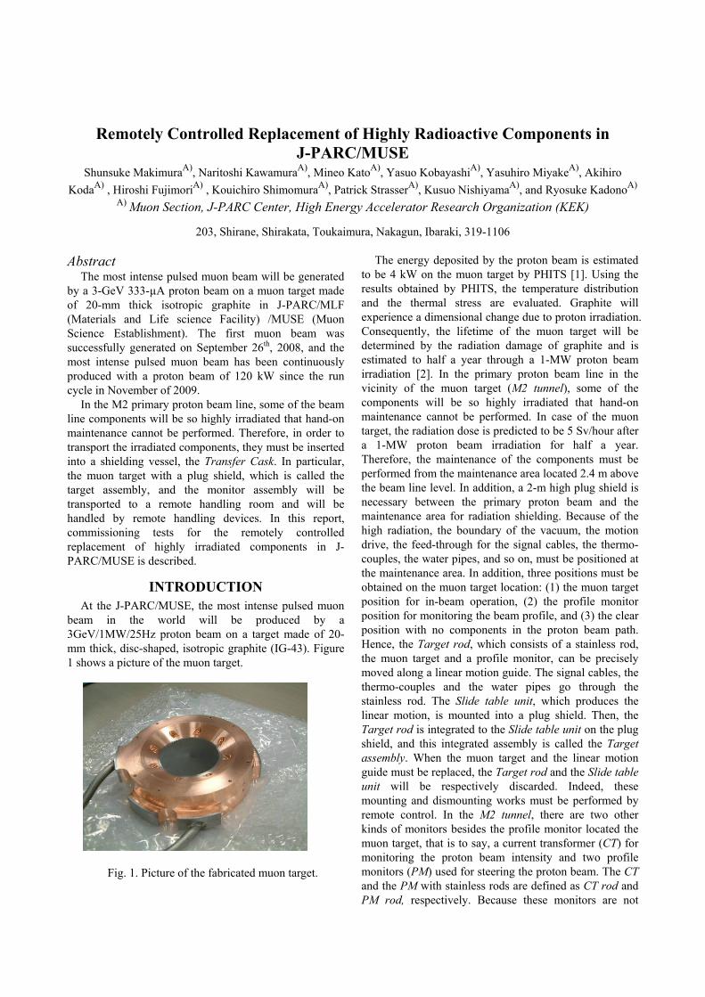
beam in the world will be produced by a 3GeV/1MW/25Hz proton beam on a target made of 20-mm thick, disc-shaped, isotropic graphite (IG-43). Figure 1 shows a picture of the muon target.
Fig. 1. Picture of the fabricated muon target.
The energy deposited by the proton beam is estimated to be 4 kW on the muon target by PHITS [1]. Using the results obtained by PHITS, the temperature distribution and the thermal stress are evaluated. Graphite will experience a dimensional change due to proton irradiation. Consequently, the lifetime of the muon target will be determined by the radiation damage of graphite and is estimated to half a year through a 1-MW proton beam irradiation [2]. In the primary proton beam line in the vicinity of the muon target (M2 tunnel), some of the components will be so highly irradiated that hand-on maintenance cannot be performed. In case of the muon target, the radiation dose is predicted to be 5 Sv/hour after a 1-MW proton beam irradiation for half a year. Therefore, the maintenance of the components must be performed from the maintenance area located 2.4 m above the beam line level. In addition, a 2-m high plug shield is necessary between the primary proton beam and the maintenance area for radiation shielding. Because of the high radiation, the boundary of the vacuum, the motion drive, the feed-through for the signal cables, the thermo-couples, the water pipes, and so on, must be positioned at the maintenance area. In addition, three positions must be obtained on the muon target location: (1) the muon target position for in-beam operation, (2) the profile monitor position for monitoring the beam profile, and (3) the clear position with no components in the proton beam path. Hence, the Target rod, which consists of a stainless rod, the muon target and a profile monitor, can be precisely moved along a linear motion guide. The signal cables, the thermo-couples and the water pipes go through the stainless rod. The Slide table unit, which produces the linear motion, is mounted into a plug shield. Then, the Target rod is integrated to the Slide table unit on the plug shield, and this integrated assembly is called the Target assembly. When the muon target and the linear motion guide must be replaced, the Target rod and the Slide table unit will be respectively discarded. Indeed, these mounting and dismounting works must be performed by remote control. In the M2 tunnel, there are two other kinds of monitors besides the profile monitor located the muon target, that is to say, a current transformer (CT) for monitoring the proton beam intensity and two profile monitors (PM) used for steering the proton beam. The CT and the PM with stainless rods are defined as CT rod and PM rod, respectively. Because these monitors are not

required to be set as precisely as the muon target, a Slide table unit with a linear motion guide is not required. The CT rod and the PM rod are mounted onto a plug shield, called the Monitor assembly.
TRANSFER CASK After a temporary storage for cooling in a storage pod,
the highly radioactive muon target, the PM and the CT are handled and replaced by the remote handling devices in the remote handling room (Hot cell). In terms of the muon target, it is also transported to a drying room for drying the water in the cooling piping, and an under-ground storage room for long-term storage. The scrapers, which collimate the scattered proton beam on the muon target, and the remote controlled vacuum connections, called pillowseals, are also stored in the storage pod, if they break down. When these components are transported in the large equipments handling room, which can be accessed for some ordinary hands-on maintenance, they must be inserted into a shielding vessel, the Transfer cask. Then the Transfer cask is set on afloor slide door dividing the large equipments room from the Hot cell. The radioactive components are then lowered into the Hot cell through the opened hatch. Table 1 shows the handled components by the Transfer cask and their locations with the lowered length. Figure 2 illustrates the movements of the Target assembly in MLF.
Table 1: Handled components by the Transfer cask and
their locations.
Location Beam line
Storage pod
Hot cell
Drying room
UG Storage
Lowered length 8m 7m 15m 23m 26m
Target √ √ √ √ √ PM, CT √ √ √ Scraper √ √ Pillowseal √ √
Fig. 2. Schematic drawing for the movements of the Target assembly and the lowered length on the locations.
The Transfer cask is composed mainly of a bottom shielding sliding door, a shielding case, two chains, a gripper, an up-down motor and a gripper motor. The maximum weight of the handled component is 6 tons for the scraper. When the Transfer cask is installed on the beam line, the base will be set at a floor level of 6 m on the steps used for the M2 tunnel ceiling shield blocks. The reproducibility of setting the Transfer cask is 0.5 mm by using embedded guides in the MLF building. The gripper can catch a component and hang it into the Transfer cask. Figure 3 shows the Transfer cask installed on the beam line over the muon target.
Fig. 3. Transfer Cask on the beam line over the muon
target. The interlock system to protect the Transfer cask and
its component is performed by a PLC control unit. The bottom shielding sliding door can be opened only when the gripper is in the upper position. Because the distance from the highest position of the gripper to the setting location of the Target assembly in the under-ground storage room is 26 m, a simple structure of the motion system is preferable. Therefore, the up-down motion and the catch-release motion are performed just by two chains. The two chains are hanged by two gear wheels, which can be independently moved in the vertical direction. When a component is lifted or lowered, both chains are wound or unwound respectively. On the other hand, when a component is gripped or released, the two gear wheels are vertically moved in opposite directions, so as to open or close the hook. Figure 4 illustrates the schematic view of the gripper. The weight of the component is measured by two load cells fixed under the two gear wheels. The position of the component is measured by an encoder attached to the up-down motor. The gripper can catch or release only when there is no weight measured by the load cells, and the component is in the appropriate position. During the up-down motion, any error from an over-load, an under-load and an unbalanced load are carefully monitored.

Fig. 4. Schematic view of the gripper.
REMOTELY CONTROLLED REPLACEMENT IN THE HOT CELL
In the Hot cell, the replacements are performed by some remote handling devices, such as a plug stand, an exchange device, a cutting device, a power manipulator, several master slave manipulators, an in-cell crane, an attachment rack and a movable rack. The plug stand can be rotated by 360 degrees, and is utilized to set several radioactive assemblies. Because it is used in common with several apparatuses for the neutron source, a plug attachment for our assemblies is necessary. The exchange device gives up-down motion, left-right motion, forward-backward motion and rotation to dismount the Target rod from the plug shield. A rod attachment for the muon components is also necessary. Figure 5 illustrates the top view of the Hot cell and the different locations of the remote handling devices.
Fig. 5. Top view of the Hot cell and locations of the remote handling devices.
Though the replacement of the Target rod is described
here, the replacements of the PM rod, the CT rod and the Slide table unit are very similar. At first, a shielding hatch is opened during a shutdown period to introduce the components for the replacement of the Target rod from the large equipments handling room into the Hot cell. The plug stand attachment for the Target assembly is lowered down through the opened hatch by a crane in the large equipments handling room, and is transported and set by the in-cell crane on the plug stand. The rod attachment
with a new Target rod and an empty rod attachment for the used Target rod, which cannot stand independently, are also lowered carried by the movable rack and set on the attachment rack. After completing the preparation, the shielding hatch is closed. Then the used Target assembly will be lowered from the Transfer cask on the plug stand attachment. Simultaneously, the empty rod attachment is attached to the exchange device. Then the upper and lower holders of Target rod are held by the upper and lower supports of the rod attachment, respectively. The fixing bolts are loosened by a power-manipulator, which can handle the bolts for remote handling. Finally, the Target rod is dismounted from the plug shield by the upward motion and the backward motion of the exchange device. The used Target rod is given to the cutting device, which has two holding mechanisms and a cutter. The empty attachment is remotely transported to the attachment rack by the in-cell crane. Figure 6 shows pictures in the remote handling room.
Fig. 6. Pictures in the remote handling room. Then another attachment with a new Target rod is set
on the exchange device by the in-cell crane. Finally, the new Target rod is fixed on the plug shield and the power manipulator tightens the bolts.
When the attachments were designed, we took attention to how the misalignment of the attachment against the Target rod was detected. The misalignment is piled up from the tolerances of each device, i.e., between the plug stand and the plug stand attachment, between the plug stand attachment and the Target assembly, between the Target rod and the rod attachment, and between the rod attachment and the exchange device. The misalignment is detected from the observation through leaden windows and several cameras in the Hot cell. Simultaneously, the loads from the motion of the exchange device are also monitored. Moreover, the exchange device has backlashes for each motion, and in particular a backlash for the rotation of 0.2 rad, which corresponds to a 5-mm backlash with an 1.5-m arm length. Therefore a constant sequence must be kept at all times.
The weight centre of every component must be carefully considered, because they are transported and set
on the devices without manual guidance. In particular, the rod attachment must have two hanging positions, because it has two weight centres, one with a Target rod and another without. The balance of the rod attachment is adjusted by the position of the hanging points and some counter weights.
COMMISIONING TESTS IN MLF The hanging tests of the muon target, the PM, the CT
and the two scrapers for all of the locations, and the pillowseals for the typical locations by the Transfer cask were successfully completed in the MLF building in March of 2008.
When the used Target rod is replaced, a new Target rod must have been prepared in advance in the Hot cell. Consequently, two rod attachments are necessary at the same time. At present, two rod attachments (rod attachment #1 and #2) were fabricated, as well as one pair of Target assembly (Target assembly #1 and #2) composed of the Target rod #1 and #2, and the plug shield #1 and #2, respectively. Using the rod attachment #1, the remotely controlled replacement tests for the Target assembly #2, the PM and the CT were performed and successfully completed in March and April of 2008, before the first proton beam operation. Continuously, using the rod attachment #2, the replacement test for the Target assembly #2, not yet irradiated, was performed and successfully completed in August of 2008. Figure 7 shows a picture of the target replacement in the Hot cell.
Fig. 7. Picture of the target replacement in the Hot cell. In August and September of 2009, the remote
controlled commissioning tests using the radioactive Target assembly #1 was performed. In these tests, the following items were aimed: (1) measure the principal dimensions of the Target assembly #1, which had not yet been handled, (2) establish a method to measure the dimension remotely, (3) observe the radioactive muon target and measure its radiation dose, and (4) to strengthen the experience of the remote controlled replacement for our group. When the Target rod is replaced by remote handling, the relative position of the lower support against the upper support is important. The misalignment at the upper support of the rod attachment against the upper holder of the Target rod can be detected
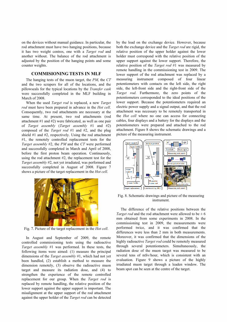
by the load on the exchange device. However, because both the exchange device and the Target rod are rigid, the relative position of the upper holder against the lower holder must correspond with the relative position of the upper support against the lower support. Therefore, the relative position of the Target rod #1 was measured by remote handling in the commissioning test in 2009. The lower support of the rod attachment was replaced by a measuring instrument composed of four linear potentiometers with contacts on the left side, the right side, the left-front side and the right-front side of the Target rod. Furthermore, the zero points of the potentiometers corresponded to the ideal positions of the lower support. Because the potentiometers required an electric power supply and a signal output, and that the rod attachment was necessary to be remotely transported in the Hot cell where no one can access for connecting cables, four displays and a battery for the displays and the potentiometers were prepared and attached to the rod attachment. Figure 8 shows the schematic drawings and a picture of the measuring instrument.
Fig. 8. Schematic drawings and picture of the measuring
instrument. The difference of the relative positions between the
Target rod and the rod attachment were allowed to be ± 6 mm obtained from some experiments in 2008. In the commissioning test in 2009, the measurements were performed twice, and it was confirmed that the differences were less than 2 mm in both measurements. Moreover, it was confirmed that the dimensions of the highly radioactive Target rod could be remotely measured through several potentiometers. Simultaneously, the radiation dose of the muon target was measured to be several tens of mSv/hour, which is consistent with an evaluation. Figure 9 shows a picture of the highly irradiated muon target through a leaden window. The beam spot can be seen at the centre of the target.
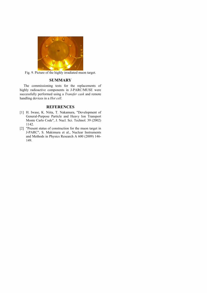
Fig. 9. Picture of the highly irradiated muon target.
SUMMARY The commissioning tests for the replacements of
highly radioactive components in J-PARC/MUSE were successfully performed using a Transfer cask and remote handling devices in a Hot cell.
REFERENCES [1] H. Iwase, K. Niita, T. Nakamura, "Development of
General-Purpose Particle and Heavy Ion Transport Monte Carlo Code", J. Nucl. Sci. Technol. 39 (2002) 1142.
[2] "Present status of construction for the muon target in J-PARC", S. Makimura et al., Nuclear Instruments and Methods in Physics Research A 600 (2009) 146-149.