review chapter 6 - الصفحات الشخصية | الجامعة الإسلامية...
TRANSCRIPT
Review
Chapter 6Fatigue Failure Resulting from Variable Loading
Mohammad Suliman Abuhaiba, Ph.D., PE1
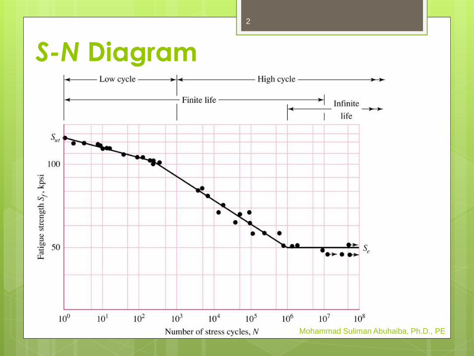
S-N Diagram
Mohammad Suliman Abuhaiba, Ph.D., PE
2
S-N Diagram for Steel
Stress levels below Se : infinite life
103 to 106 cycles: finite life
Below 103 cycles: low cycle
Yielding usually occurs before fatigue
Mohammad Suliman Abuhaiba, Ph.D., PE
3
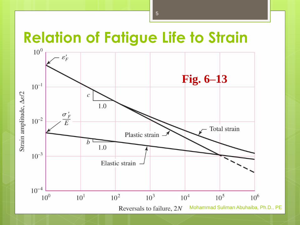
Relation of Fatigue Life to Strain
Figure 6–13: relationship of fatigue life to
true-strain amplitude
Fatigue ductility coefficient e'F = true strainat which fracture occurs in one reversal
(point A in Fig. 6–12)
Fatigue strength coefficient s'F = truestress corresponding to fracture in one
reversal (point A in Fig. 6–12)
Mohammad Suliman Abuhaiba, Ph.D., PE
4
Relation of Fatigue Life to Strain
Mohammad Suliman Abuhaiba, Ph.D., PE
Fig. 6–13
5
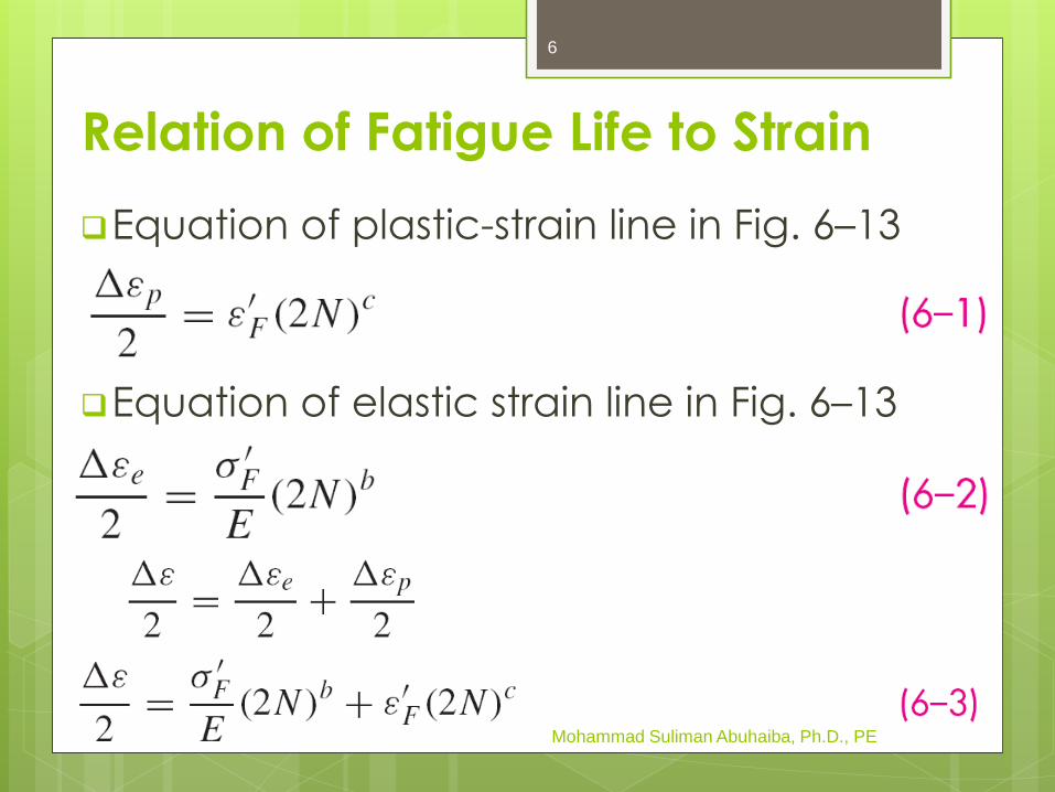
Equation of plastic-strain line in Fig. 6–13
Equation of elastic strain line in Fig. 6–13
Mohammad Suliman Abuhaiba, Ph.D., PE
Relation of Fatigue Life to Strain
6

Fatigue ductility exponent c = slope ofplastic-strain line
2N stress reversals = N cycles
Fatigue strength exponent b = slope of
elastic-strain line
Mohammad Suliman Abuhaiba, Ph.D., PE
Relation of Fatigue Life to Strain
7

Manson-Coffin: relationship between
fatigue life and total strain
Table A–23: values of coefficients &
exponents
Mohammad Suliman Abuhaiba, Ph.D., PE
Relation of Fatigue Life to Strain
8
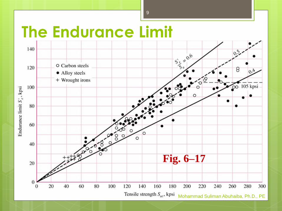
The Endurance Limit
Mohammad Suliman Abuhaiba, Ph.D., PE
Fig. 6–17
9
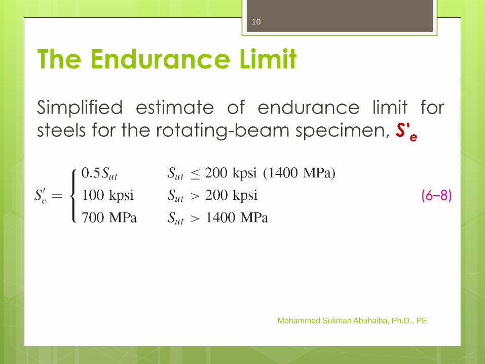
Simplified estimate of endurance limit for
steels for the rotating-beam specimen, S'e
Mohammad Suliman Abuhaiba, Ph.D., PE
The Endurance Limit
10
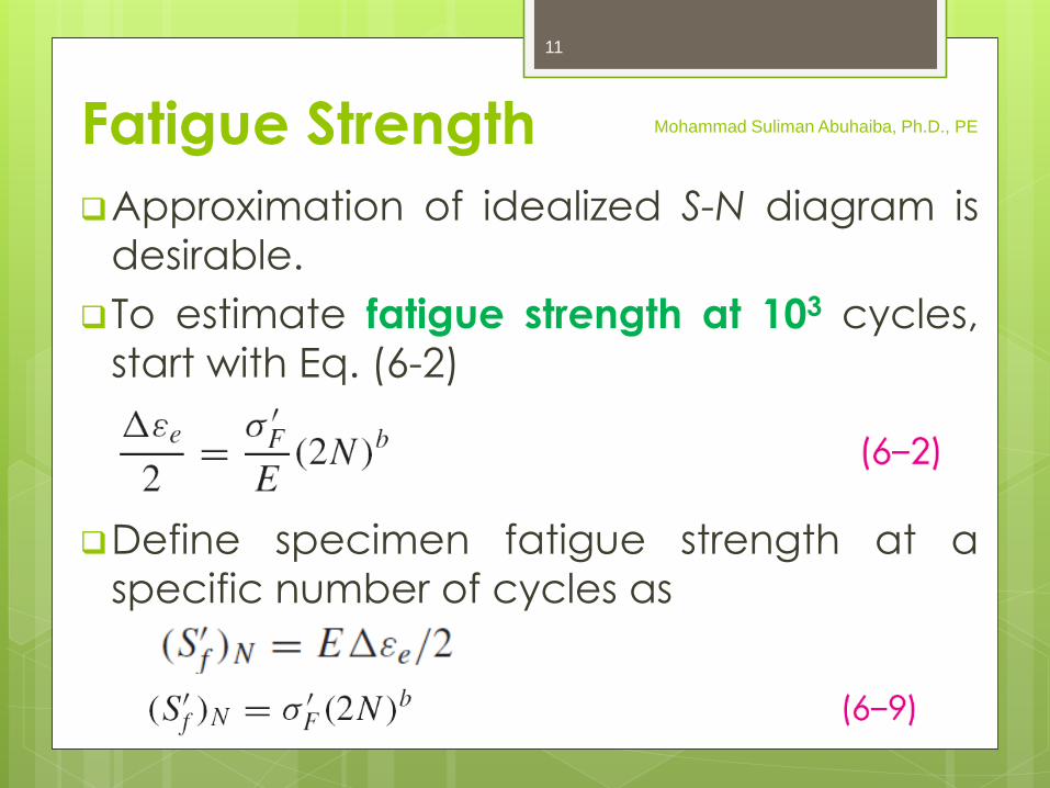
Fatigue Strength
Approximation of idealized S-N diagram is
desirable.
To estimate fatigue strength at 103 cycles,
start with Eq. (6-2)
Define specimen fatigue strength at a
specific number of cycles as
Mohammad Suliman Abuhaiba, Ph.D., PE
11

Fatigue Strength
At 103 cycles,
f = fraction of Sut represented by
SAE approximation for steels with HB ≤ 500,
Mohammad Suliman Abuhaiba, Ph.D., PE
310( )fS
12

Fatigue Strength
To find b, substitute endurance strength
and corresponding cycles into Eq. (6–9)
and solve for b
Mohammad Suliman Abuhaiba, Ph.D., PE
13
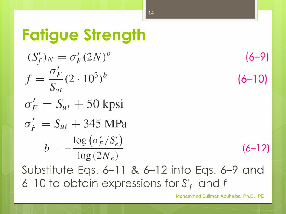
Fatigue Strength
Substitute Eqs. 6–11 & 6–12 into Eqs. 6–9 and
6–10 to obtain expressions for S'f and fMohammad Suliman Abuhaiba, Ph.D., PE
14
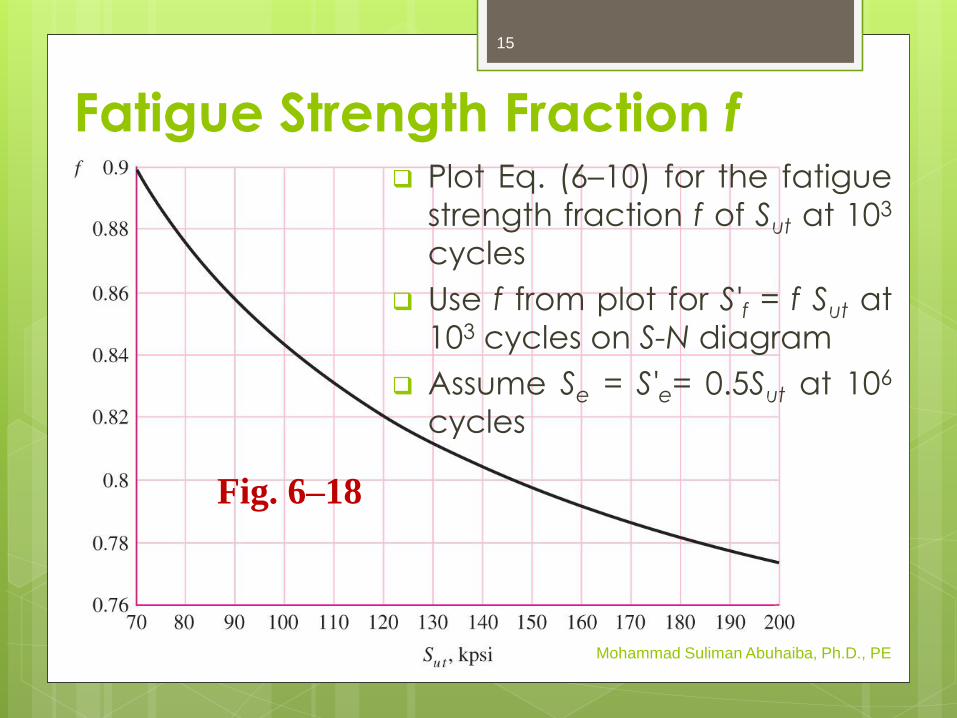
Fatigue Strength Fraction f Plot Eq. (6–10) for the fatigue
strength fraction f of Sut at 103
cycles
Use f from plot for S'f = f Sut at
103 cycles on S-N diagram
Assume Se = S'e= 0.5Sut at 106
cycles
Mohammad Suliman Abuhaiba, Ph.D., PE
Fig. 6–18
15
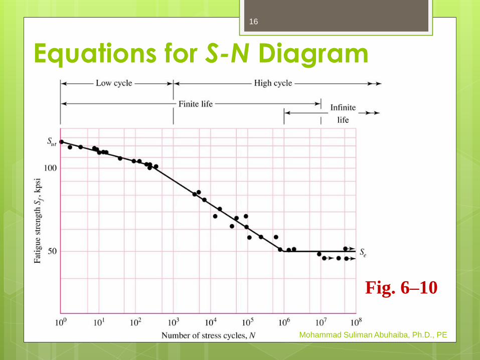
Equations for S-N Diagram
Mohammad Suliman Abuhaiba, Ph.D., PE
Fig. 6–10
16
Mohammad Suliman Abuhaiba, Ph.D., PE
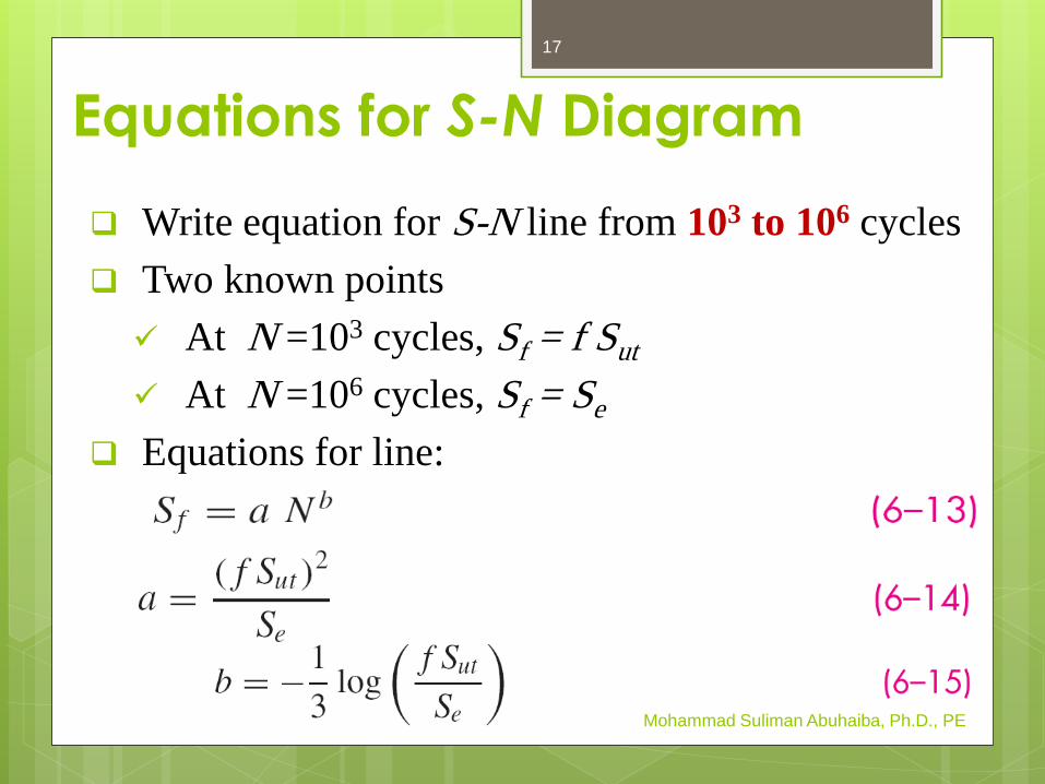
Write equation for S-N line from 103 to 106 cycles
Two known points
At N =103 cycles, Sf = f Sut
At N =106 cycles, Sf = Se
Equations for line:
Equations for S-N Diagram
17
Mohammad Suliman Abuhaiba, Ph.D., PE
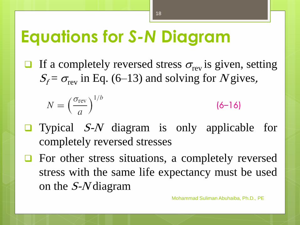
If a completely reversed stress srev is given, setting
Sf = srev in Eq. (6–13) and solving for N gives,
Typical S-N diagram is only applicable for
completely reversed stresses
For other stress situations, a completely reversed
stress with the same life expectancy must be used
on the S-N diagram
Equations for S-N Diagram
18
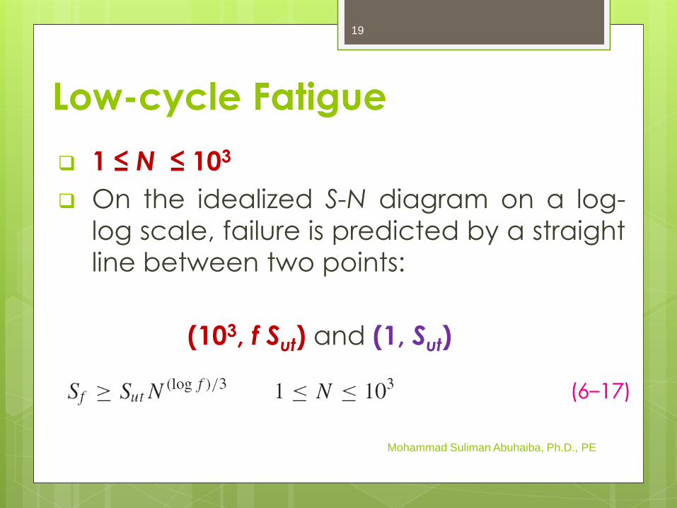
Low-cycle Fatigue
1 ≤ N ≤ 103
On the idealized S-N diagram on a log-
log scale, failure is predicted by a straight
line between two points:
(103, f Sut) and (1, Sut)
Mohammad Suliman Abuhaiba, Ph.D., PE
19

Example 6-2
Given a 1050 HR steel, estimate
a. the rotating-beam endurance limit at 106
cycles.
b. the endurance strength of a polished
rotating-beam specimen corresponding
to 104 cycles to failure
c. the expected life of a polished rotating-
beam specimen under a completely
reversed stress of 55 kpsi.
Mohammad Suliman Abuhaiba, Ph.D., PE
20

Endurance Limit Modifying Factors
Mohammad Suliman Abuhaiba, Ph.D., PE
ka = surface condition factor
kb = size factor
kc = load factor
kd = temperature factor
ke = reliability factor
kf = miscellaneous-effects factor
Se’ = rotary-beam test specimen endurance limit
Se = endurance limit at the critical location of a
machine part in the geometry and condition of
use
21

Surface Factor ka
ka is a function of ultimate strength
Higher strengths more sensitive to rough
surfaces
Table 6–2
Mohammad Suliman Abuhaiba, Ph.D., PE
22
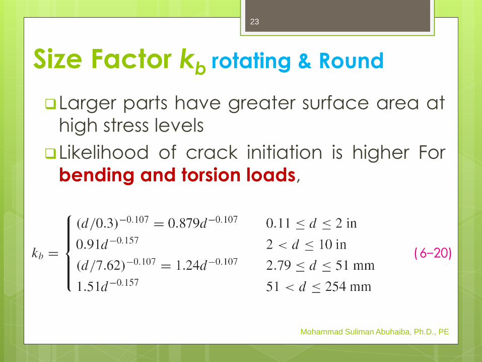
Size Factor kb rotating & Round
Larger parts have greater surface area at
high stress levels
Likelihood of crack initiation is higher For
bending and torsion loads,
Mohammad Suliman Abuhaiba, Ph.D., PE
23
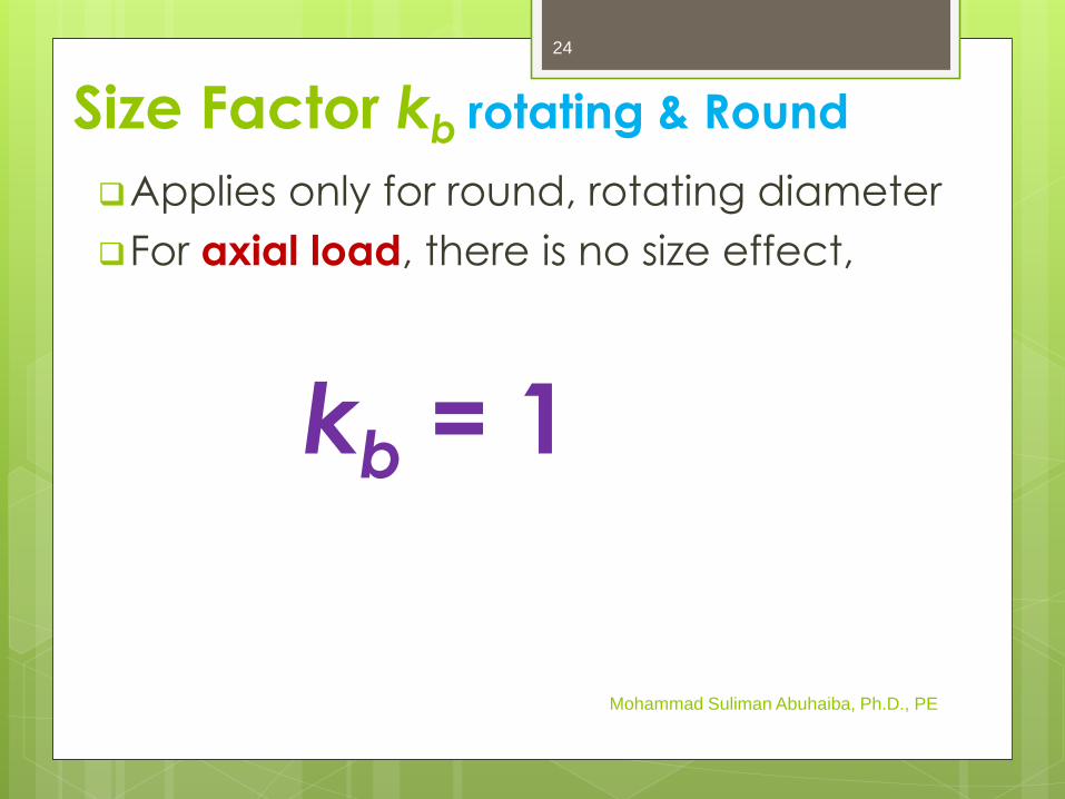
Size Factor kb rotating & Round
Applies only for round, rotating diameter
For axial load, there is no size effect,
kb = 1
Mohammad Suliman Abuhaiba, Ph.D., PE
24
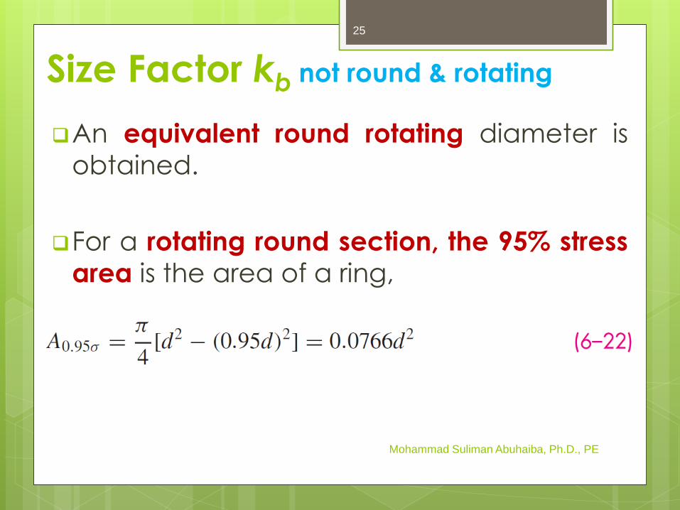
An equivalent round rotating diameter is
obtained.
For a rotating round section, the 95% stress
area is the area of a ring,
Mohammad Suliman Abuhaiba, Ph.D., PE
Size Factor kb not round & rotating
25
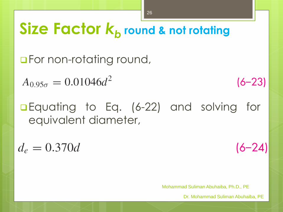
For non-rotating round,
Equating to Eq. (6-22) and solving for
equivalent diameter,
Size Factor kb round & not rotating
Dr. Mohammad Suliman Abuhaiba, PE
Mohammad Suliman Abuhaiba, Ph.D., PE
26
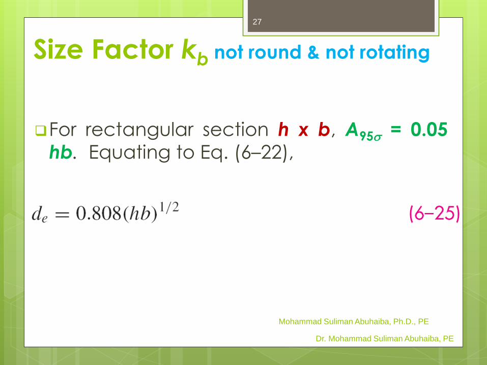
For rectangular section h x b, A95s = 0.05
hb. Equating to Eq. (6–22),
Size Factor kb not round & not rotating
Dr. Mohammad Suliman Abuhaiba, PE
Mohammad Suliman Abuhaiba, Ph.D., PE
27
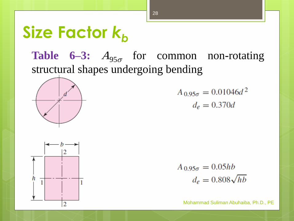
Size Factor kb
Mohammad Suliman Abuhaiba, Ph.D., PE
Table 6–3: A95s for common non-rotating
structural shapes undergoing bending
28

Loading Factor kc
Accounts for changes in endurance limit
for different types of fatigue loading.
Only to be used for single load types.
Use Combination Loading method (Sec. 6–
14) when more than one load type is
present.
Mohammad Suliman Abuhaiba, Ph.D., PE
29

Temperature Factor kd
Mohammad Suliman Abuhaiba, Ph.D., PE
Table 6–4
30

A fourth-order polynomial curve fit of the
data of Table 6–4 can be used in place of
the table,
Temperature Factor kd
Mohammad Suliman Abuhaiba, Ph.D., PE
31

Reliability Factor ke
Fig. 6–17, S'e = 0.5 Sut is typical of the data
and represents 50% reliability.
Reliability factor adjusts to other reliabilities.
Mohammad Suliman Abuhaiba, Ph.D., PE
32

Reliability Factor ke
Mohammad Suliman Abuhaiba, Ph.D., PE
Fig. 6–17
33
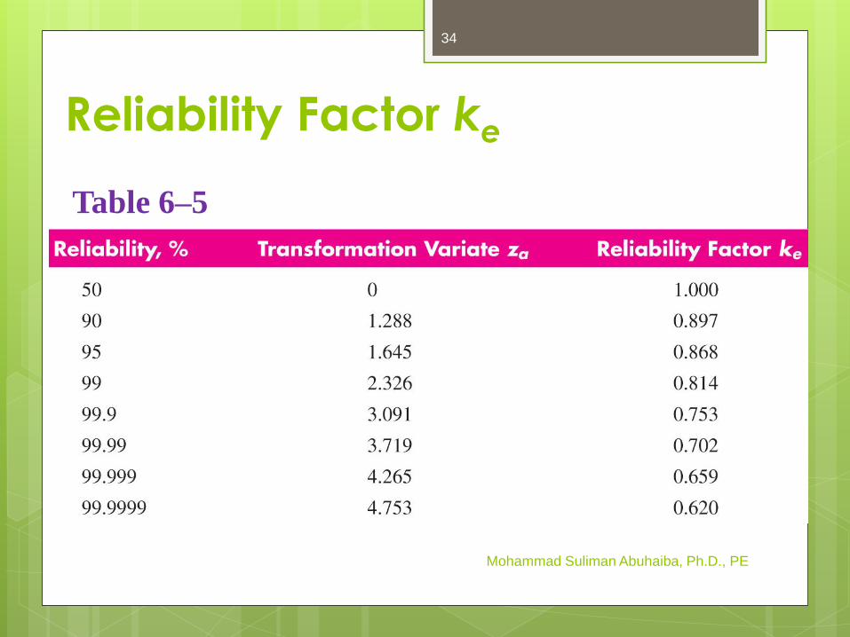
Reliability Factor ke
Mohammad Suliman Abuhaiba, Ph.D., PE
Table 6–5
34

Stress Concentration and Notch
Sensitivity
Kt = geometric stress-concentration factor
(Appendix A–15)
q = notch sensitivity, ranging from 0 (not sensitive)
to 1 (fully sensitive)
For q = 0, Kf = 1
For q = 1, Kf = Kt
Mohammad Suliman Abuhaiba, Ph.D., PE
35

Notch SensitivityFig. 6–20: q for bending or axial loading
Mohammad Suliman Abuhaiba, Ph.D., PE
Fig. 6–20
Kf = 1 + q( Kt – 1)
36
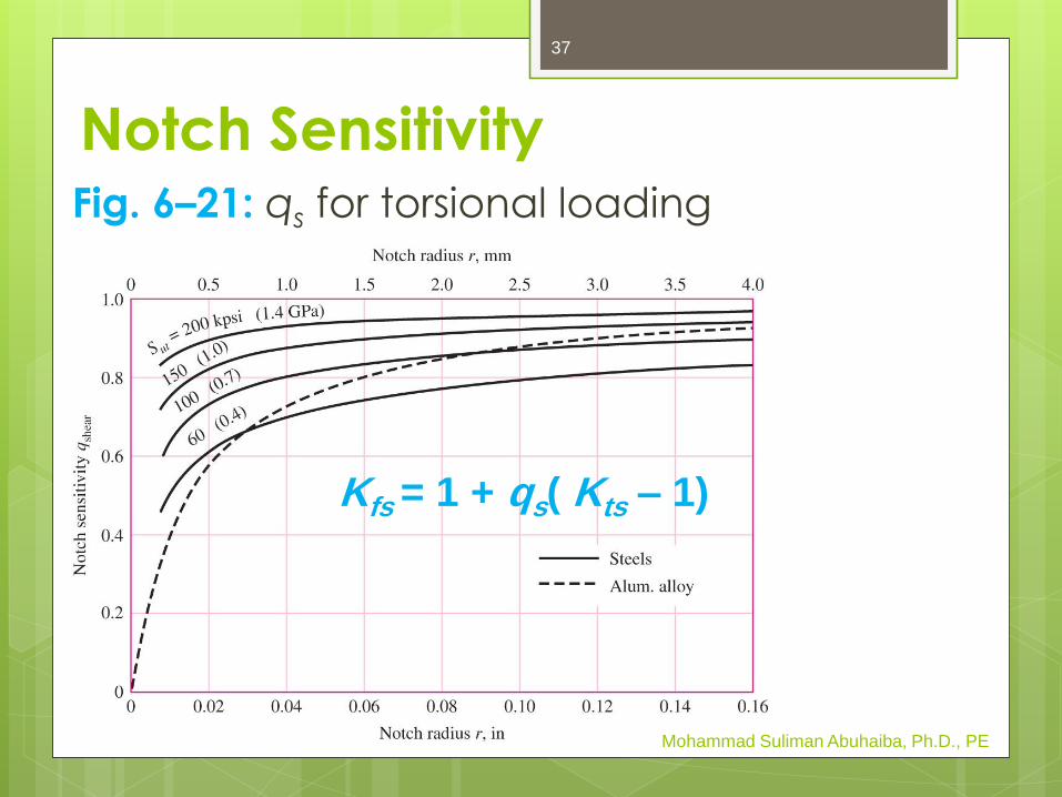
Notch SensitivityFig. 6–21: qs for torsional loading
Mohammad Suliman Abuhaiba, Ph.D., PE
Kfs = 1 + qs( Kts – 1)
37

Notch SensitivityUse curve fit equations for Figs. 6–20 & 6–21
to get notch sensitivity, or go directly to Kf .
Mohammad Suliman Abuhaiba, Ph.D., PE
Bending or axial:
Torsion:
38
Notch Sensitivity for Cast Irons
Recommended: q = 0.2 for cast irons.
Mohammad Suliman Abuhaiba, Ph.D., PE
39
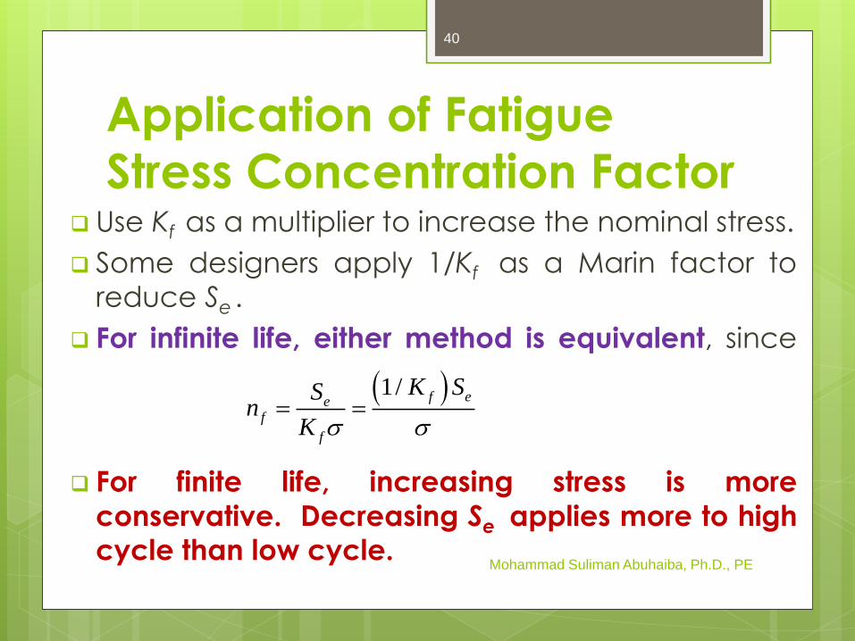
Application of Fatigue
Stress Concentration Factor Use Kf as a multiplier to increase the nominal stress.
Some designers apply 1/Kf as a Marin factor to
reduce Se .
For infinite life, either method is equivalent, since
For finite life, increasing stress is more
conservative. Decreasing Se applies more to highcycle than low cycle.
Mohammad Suliman Abuhaiba, Ph.D., PE
1/ f eef
f
K SSn
K s s
40

Example 6-7
For the step-shaft of Ex. 6–6, it is
determined that the fully corrected
endurance limit is Se = 280 MPa. Consider
the shaft undergoes a fully reversing
nominal stress in the fillet of (σrev)nom = 260
MPa. Estimate the number of cycles to
failure.
Mohammad Suliman Abuhaiba, Ph.D., PE
41

Characterizing Fluctuating
Stresses
Mohammad Suliman Abuhaiba, Ph.D., PE
Stress ratio
Amplitude ratio
42
Application of Kf for Fluctuating
StressesFor fluctuating loads at points with stress
concentration, Kf should be applied to
both alternating and midrange stress
components.
Mohammad Suliman Abuhaiba, Ph.D., PE
43
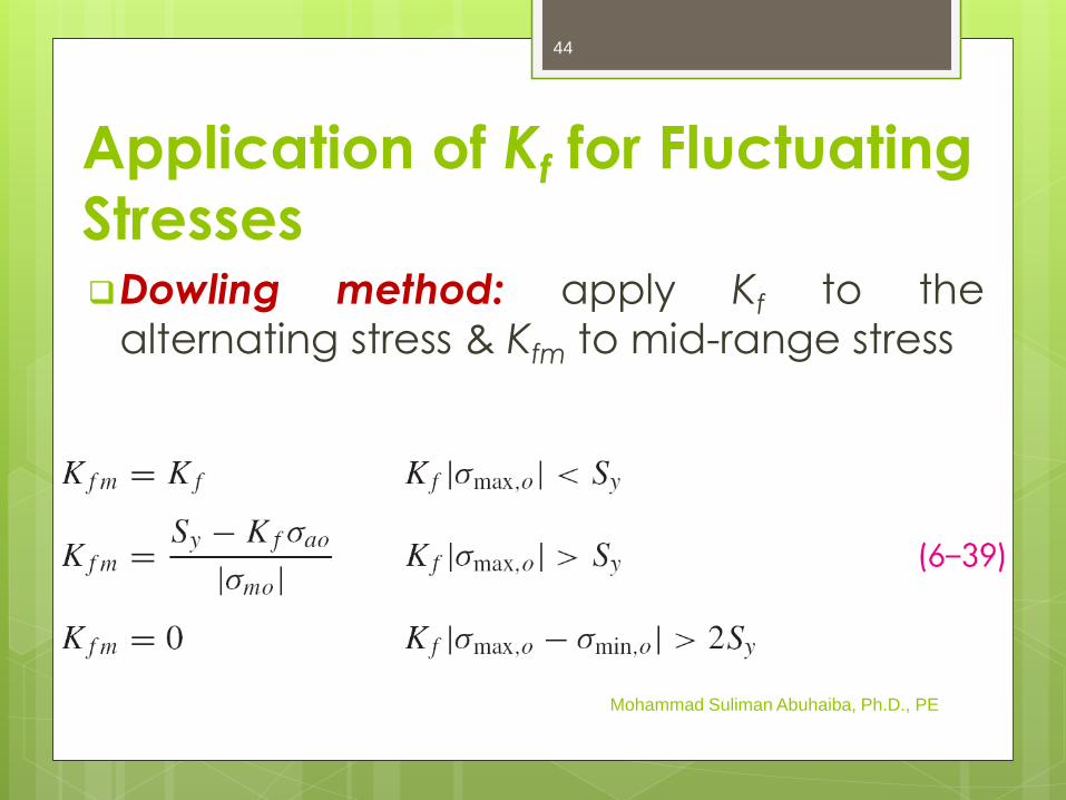
Application of Kf for Fluctuating
StressesDowling method: apply Kf to the
alternating stress & Kfm to mid-range stress
Mohammad Suliman Abuhaiba, Ph.D., PE
44
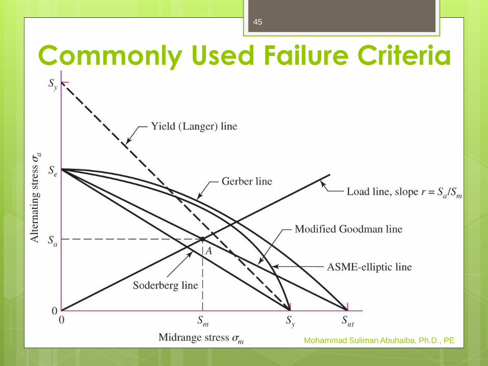
Commonly Used Failure Criteria
Mohammad Suliman Abuhaiba, Ph.D., PE
45

Equations for Commonly
Used Failure Criteria
Mohammad Suliman Abuhaiba, Ph.D., PE
46
Mohammad Suliman Abuhaiba, Ph.D., PE
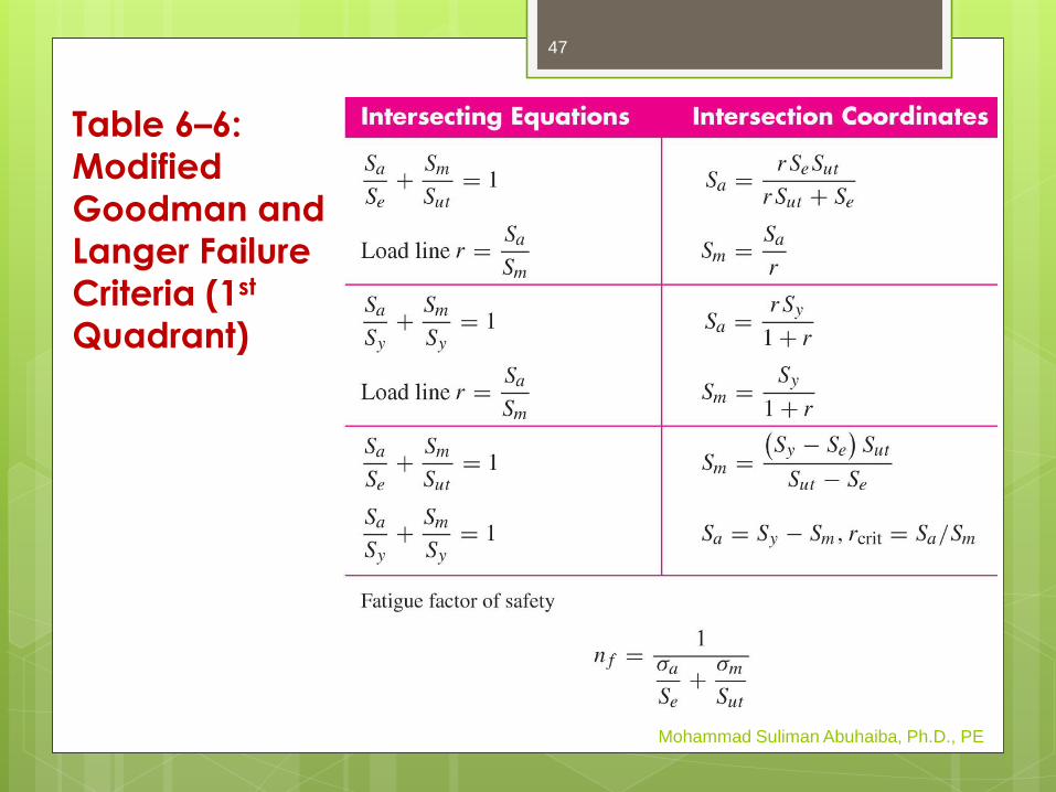
Table 6–6:
Modified
Goodman and
Langer Failure
Criteria (1st
Quadrant)
47

Table 6–7:
Gerber &
Langer Failure
Criteria (1st
Quadrant)
Mohammad Suliman Abuhaiba, Ph.D., PE
48
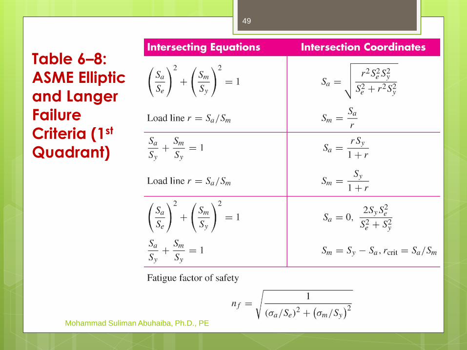
Table 6–8:
ASME Elliptic
and Langer
Failure
Criteria (1st
Quadrant)
Mohammad Suliman Abuhaiba, Ph.D., PE
49
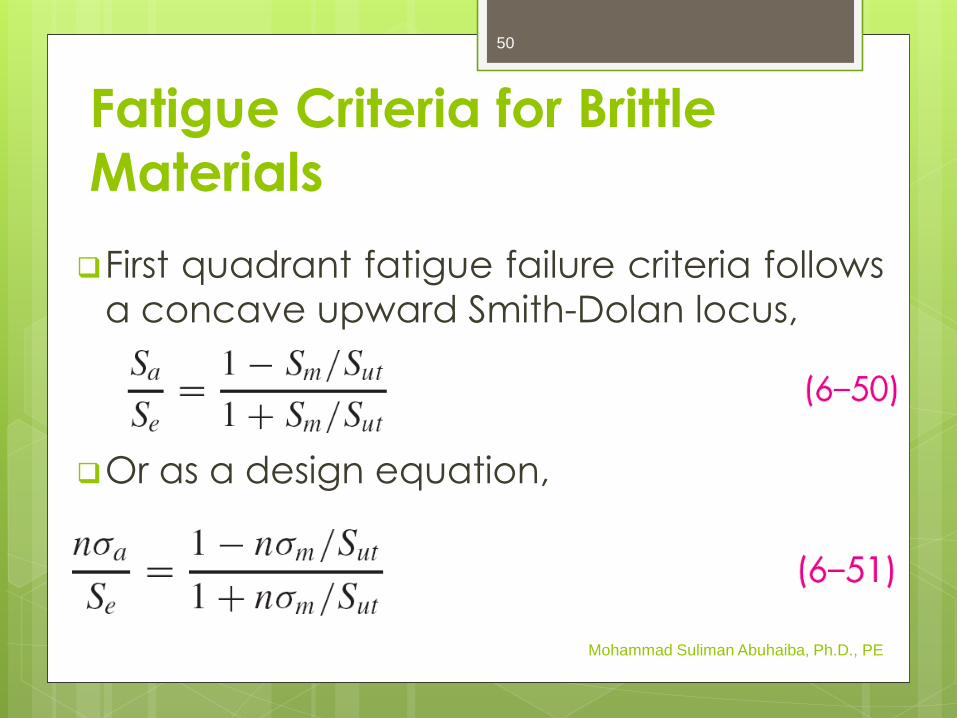
Fatigue Criteria for Brittle
Materials
First quadrant fatigue failure criteria follows
a concave upward Smith-Dolan locus,
Or as a design equation,
Mohammad Suliman Abuhaiba, Ph.D., PE
50
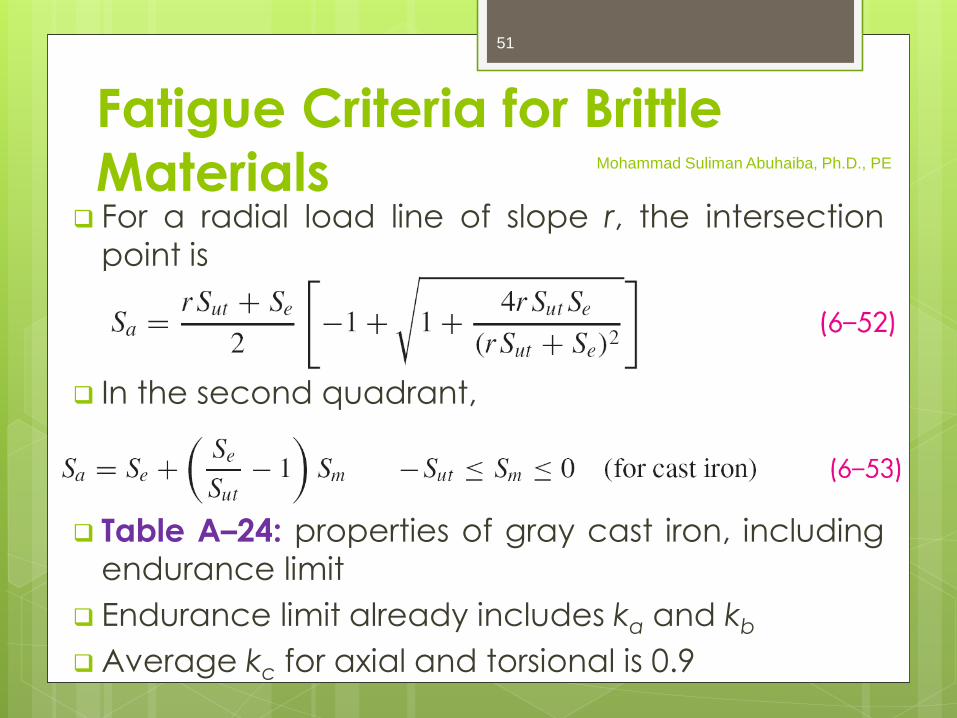
Fatigue Criteria for Brittle
Materials For a radial load line of slope r, the intersection
point is
In the second quadrant,
Table A–24: properties of gray cast iron, including
endurance limit
Endurance limit already includes ka and kb
Average kc for axial and torsional is 0.9
Mohammad Suliman Abuhaiba, Ph.D., PE
51
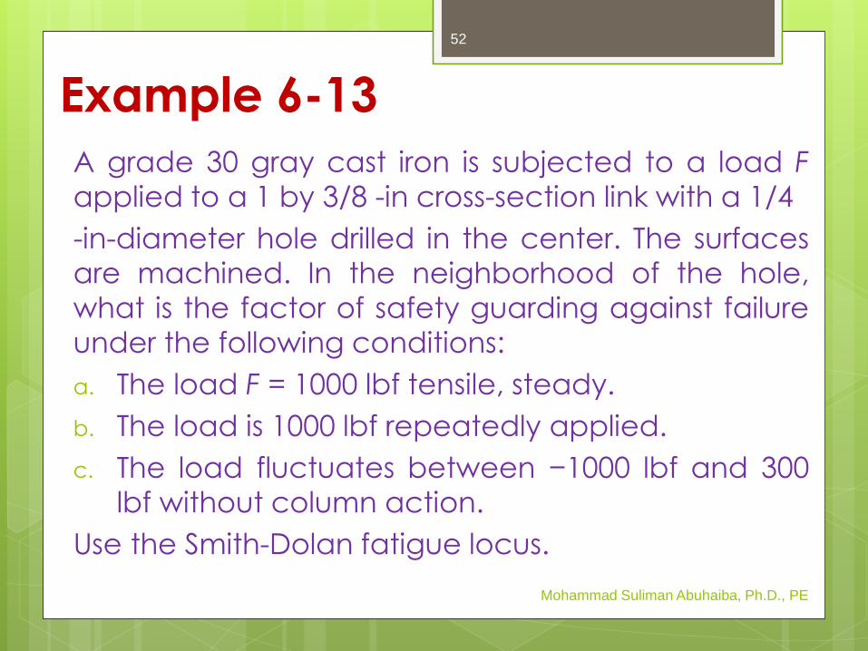
Example 6-13
A grade 30 gray cast iron is subjected to a load F
applied to a 1 by 3/8 -in cross-section link with a 1/4
-in-diameter hole drilled in the center. The surfaces
are machined. In the neighborhood of the hole,
what is the factor of safety guarding against failure
under the following conditions:
a. The load F = 1000 lbf tensile, steady.
b. The load is 1000 lbf repeatedly applied.
c. The load fluctuates between −1000 lbf and 300
lbf without column action.
Use the Smith-Dolan fatigue locus.
Mohammad Suliman Abuhaiba, Ph.D., PE
52

Example 6-13
Mohammad Suliman Abuhaiba, Ph.D., PE
53

Example 6-13
Mohammad Suliman Abuhaiba, Ph.D., PE
54

Torsional Fatigue Strength Testing: steady-stress component has no effect on
the endurance limit for torsional loading if the
material is
ductile, polished, notch-free, and cylindrical.
For less than perfect surfaces, the modified
Goodman line is more reasonable.
For pure torsion cases, use kc = 0.59 to convert
normal endurance strength to shear endurance
strength.
For shear ultimate strength, recommended to use
Mohammad Suliman Abuhaiba, Ph.D., PE
55

Combinations of Loading
Modes
For combined loading, use Distortion
Energy theory to combine them.
Obtain Von Mises stresses for both
midrange and alternating components.
Apply appropriate Kf to each type of stress.
For load factor, use kc = 1. The torsional
load factor (kc = 0.59) is inherentlyincluded in the von Mises equations.
Mohammad Suliman Abuhaiba, Ph.D., PE
56
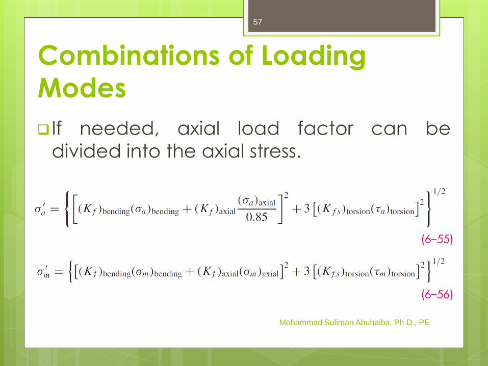
Combinations of Loading
Modes
If needed, axial load factor can be
divided into the axial stress.
Mohammad Suliman Abuhaiba, Ph.D., PE
57
Static Check for
Combination Loading
Distortion Energy theory still applies for
check of static yielding
Obtain Von Mises stress for maximum
stresses
Stress concentration factors are not
necessary to check for yielding at first
cycle
Mohammad Suliman Abuhaiba, Ph.D., PE
58

max a ms s s
Static Check for
Combination Loading
Alternate simple check is to obtain
conservative estimate of s'max by summing
s'a and s'm
≈Mohammad Suliman Abuhaiba, Ph.D., PE
1/2
2 2
max
max
3a m a m
y
y
Sn
s s s
s
59