scala1 - api.grundfos.com
TRANSCRIPT

SCALA1Installation and operating instructions
GRUNDFOS INSTRUCTIONS


SCALA1English (GB)Installation and operating instructions . . . . . . . . . . . . . . . . . . . . . . . . . . . . . . . . . . . . . . . . . . . . . . . . . . . . . . . . . . 5
Български (BG)Упътване за монтаж и експлоатация. . . . . . . . . . . . . . . . . . . . . . . . . . . . . . . . . . . . . . . . . . . . . . . . . . . . . . . . . 31
Čeština (CZ)Montážní a provozní návod . . . . . . . . . . . . . . . . . . . . . . . . . . . . . . . . . . . . . . . . . . . . . . . . . . . . . . . . . . . . . . . . . 57
Deutsch (DE)Montage- und Betriebsanleitung . . . . . . . . . . . . . . . . . . . . . . . . . . . . . . . . . . . . . . . . . . . . . . . . . . . . . . . . . . . . . 82
Dansk (DK)Monterings- og driftsinstruktion . . . . . . . . . . . . . . . . . . . . . . . . . . . . . . . . . . . . . . . . . . . . . . . . . . . . . . . . . . . . . 108
Eesti (EE)Paigaldus- ja kasutusjuhend . . . . . . . . . . . . . . . . . . . . . . . . . . . . . . . . . . . . . . . . . . . . . . . . . . . . . . . . . . . . . . . 133
Español (ES)Instrucciones de instalación y funcionamiento . . . . . . . . . . . . . . . . . . . . . . . . . . . . . . . . . . . . . . . . . . . . . . . . . . 158
Suomi (FI)Asennus- ja käyttöohjeet . . . . . . . . . . . . . . . . . . . . . . . . . . . . . . . . . . . . . . . . . . . . . . . . . . . . . . . . . . . . . . . . . . 185
Français (FR)Notice d'installation et de fonctionnement . . . . . . . . . . . . . . . . . . . . . . . . . . . . . . . . . . . . . . . . . . . . . . . . . . . . . 210
Ελληνικά (GR)Οδηγίες εγκατάστασης και λειτουργίας . . . . . . . . . . . . . . . . . . . . . . . . . . . . . . . . . . . . . . . . . . . . . . . . . . . . . . . . 236
Hrvatski (HR)Montažne i pogonske upute . . . . . . . . . . . . . . . . . . . . . . . . . . . . . . . . . . . . . . . . . . . . . . . . . . . . . . . . . . . . . . . . 262
Magyar (HU)Telepítési és üzemeltetési utasítás. . . . . . . . . . . . . . . . . . . . . . . . . . . . . . . . . . . . . . . . . . . . . . . . . . . . . . . . . . . 287
Italiano (IT)Istruzioni di installazione e funzionamento . . . . . . . . . . . . . . . . . . . . . . . . . . . . . . . . . . . . . . . . . . . . . . . . . . . . . 313
Lietuviškai (LT)Įrengimo ir naudojimo instrukcija . . . . . . . . . . . . . . . . . . . . . . . . . . . . . . . . . . . . . . . . . . . . . . . . . . . . . . . . . . . . 338
Latviešu (LV)Uzstādīšanas un ekspluatācijas instrukcija . . . . . . . . . . . . . . . . . . . . . . . . . . . . . . . . . . . . . . . . . . . . . . . . . . . . 363
Nederlands (NL)Installatie- en bedieningsinstructies . . . . . . . . . . . . . . . . . . . . . . . . . . . . . . . . . . . . . . . . . . . . . . . . . . . . . . . . . . 388
Polski (PL)Instrukcja montażu i eksploatacji . . . . . . . . . . . . . . . . . . . . . . . . . . . . . . . . . . . . . . . . . . . . . . . . . . . . . . . . . . . . 414
Português (PT)Instruções de instalação e funcionamento . . . . . . . . . . . . . . . . . . . . . . . . . . . . . . . . . . . . . . . . . . . . . . . . . . . . . 439
Română (RO)Instrucţiuni de instalare şi utilizare . . . . . . . . . . . . . . . . . . . . . . . . . . . . . . . . . . . . . . . . . . . . . . . . . . . . . . . . . . . 465
Srpski (RS)Uputstvo za instalaciju i rad . . . . . . . . . . . . . . . . . . . . . . . . . . . . . . . . . . . . . . . . . . . . . . . . . . . . . . . . . . . . . . . . 490
Русский (RU)Паспорт, Руководство по монтажу и эксплуатации. . . . . . . . . . . . . . . . . . . . . . . . . . . . . . . . . . . . . . . . . . . . . 515
Svenska (SE)Monterings- och driftsinstruktion. . . . . . . . . . . . . . . . . . . . . . . . . . . . . . . . . . . . . . . . . . . . . . . . . . . . . . . . . . . . . 543
Slovensko (SI)Navodila za montažo in obratovanje . . . . . . . . . . . . . . . . . . . . . . . . . . . . . . . . . . . . . . . . . . . . . . . . . . . . . . . . . 568
Slovenčina (SK)
3
Tabl
e of
con
tent
s

Návod na montáž a prevádzku. . . . . . . . . . . . . . . . . . . . . . . . . . . . . . . . . . . . . . . . . . . . . . . . . . . . . . . . . . . . . . 593
Türkçe (TR)Montaj ve kullanım kılavuzu . . . . . . . . . . . . . . . . . . . . . . . . . . . . . . . . . . . . . . . . . . . . . . . . . . . . . . . . . . . . . . . . 618
Українська (UA)Інструкції з монтажу та експлуатації . . . . . . . . . . . . . . . . . . . . . . . . . . . . . . . . . . . . . . . . . . . . . . . . . . . . . . . . 643
中文 (CN)安装和使用说明书 . . . . . . . . . . . . . . . . . . . . . . . . . . . . . . . . . . . . . . . . . . . . . . . . . . . . . . . . . . . . . . . . . . . . . . . 669
日本語 (JP)
取扱説明書. . . . . . . . . . . . . . . . . . . . . . . . . . . . . . . . . . . . . . . . . . . . . . . . . . . . . . . . . . . . . . . . . . . . . . . . . . . . . 693
한국어 (KO)설치 및 작동 지침 . . . . . . . . . . . . . . . . . . . . . . . . . . . . . . . . . . . . . . . . . . . . . . . . . . . . . . . . . . . . . . . . . . . . . . . . 717
Bosanski (BS)Montažne i pogonske upute . . . . . . . . . . . . . . . . . . . . . . . . . . . . . . . . . . . . . . . . . . . . . . . . . . . . . . . . . . . . . . . . 741
Bahasa Indonesia (ID)Petunjuk pengoperasian dan pemasangan . . . . . . . . . . . . . . . . . . . . . . . . . . . . . . . . . . . . . . . . . . . . . . . . . . . . 766
Қазақша (KZ)Орнату жəне пайдалану нұсқаулықтары. . . . . . . . . . . . . . . . . . . . . . . . . . . . . . . . . . . . . . . . . . . . . . . . . . . . . 791
Macedonian (MK)Упатства за монтирање и ракување . . . . . . . . . . . . . . . . . . . . . . . . . . . . . . . . . . . . . . . . . . . . . . . . . . . . . . . . 816
Malaysia (MY)Cara pemasangan dan pengendalian . . . . . . . . . . . . . . . . . . . . . . . . . . . . . . . . . . . . . . . . . . . . . . . . . . . . . . . . 845
Norsk (NO)Installasjons- og driftsinstruksjoner . . . . . . . . . . . . . . . . . . . . . . . . . . . . . . . . . . . . . . . . . . . . . . . . . . . . . . . . . . 870
(AR) العربيةالتشغيل و التركيب تعليمات . . . . . . . . . . . . . . . . . . . . . . . . . . . . . . . . . . . . . . . . . . . . . . . . . . . . . . . . . . . . . . . . . . . . . . 895
ไทย (TH)คำแนะนำในการติดตั้งและการใชงาน . . . . . . . . . . . . . . . . . . . . . . . . . . . . . . . . . . . . . . . . . . . . . . . . . . . . . . . . . . . 919
Tiếng Việt (VI)Hướng dẫn lắp đặt và vận hành. . . . . . . . . . . . . . . . . . . . . . . . . . . . . . . . . . . . . . . . . . . . . . . . . . . . . . . . . . . . . 945
Français (CA)Notice d'installation et de fonctionnement . . . . . . . . . . . . . . . . . . . . . . . . . . . . . . . . . . . . . . . . . . . . . . . . . . . . . 970
Español (MX)Instrucciones de instalación y operación . . . . . . . . . . . . . . . . . . . . . . . . . . . . . . . . . . . . . . . . . . . . . . . . . . . . . . 996
Íslenska (IS)Uppsetningar- og notkunarleiðbeiningar. . . . . . . . . . . . . . . . . . . . . . . . . . . . . . . . . . . . . . . . . . . . . . . . . . . . . . 1023
4 SCALA1
Table of contents
English (GB) Installation and operating instructions
Original installation and operating instructions
Table of contents1. General information . . . . . . . . . . . . . . . . . . . . . . . . 51.1 Hazard statements . . . . . . . . . . . . . . . . . . . . . . . . . . 51.2 Notes . . . . . . . . . . . . . . . . . . . . . . . . . . . . . . . . . . 51.3 Target group. . . . . . . . . . . . . . . . . . . . . . . . . . . . . . 6
2. Product introduction. . . . . . . . . . . . . . . . . . . . . . . . 62.1 Product description of SCALA 1. . . . . . . . . . . . . . . . . . 62.2 Intended use . . . . . . . . . . . . . . . . . . . . . . . . . . . . . 62.3 Pumped liquids . . . . . . . . . . . . . . . . . . . . . . . . . . . . 62.4 Identification. . . . . . . . . . . . . . . . . . . . . . . . . . . . . . 6
3. Receiving the product . . . . . . . . . . . . . . . . . . . . . . . 73.1 Inspecting the product. . . . . . . . . . . . . . . . . . . . . . . . 73.2 Scope of delivery . . . . . . . . . . . . . . . . . . . . . . . . . . . 7
4. Installation requirements . . . . . . . . . . . . . . . . . . . . . 74.1 Location . . . . . . . . . . . . . . . . . . . . . . . . . . . . . . . . 74.2 Maximum system pressure. . . . . . . . . . . . . . . . . . . . . 7
5. Mechanical installation . . . . . . . . . . . . . . . . . . . . . . 75.1 Positioning and mounting the product . . . . . . . . . . . . . . 75.2 Connecting the pipe system . . . . . . . . . . . . . . . . . . . . 85.3 Installation examples . . . . . . . . . . . . . . . . . . . . . . . 10
6. Electrical connection . . . . . . . . . . . . . . . . . . . . . . 126.1 Connecting products with a plug . . . . . . . . . . . . . . . . 126.2 Connecting products without a plug . . . . . . . . . . . . . . 126.3 Motor protection . . . . . . . . . . . . . . . . . . . . . . . . . . 12
7. Starting up the product . . . . . . . . . . . . . . . . . . . . . 127.1 Priming the product . . . . . . . . . . . . . . . . . . . . . . . . 127.2 Starting up the pump . . . . . . . . . . . . . . . . . . . . . . . 127.3 Operation . . . . . . . . . . . . . . . . . . . . . . . . . . . . . . 137.4 Shaft seal run-in . . . . . . . . . . . . . . . . . . . . . . . . . . 13
8. Control functions . . . . . . . . . . . . . . . . . . . . . . . . . 138.1 Operating panel . . . . . . . . . . . . . . . . . . . . . . . . . . 138.2 Auto reset . . . . . . . . . . . . . . . . . . . . . . . . . . . . . . 148.3 Dry-running protection. . . . . . . . . . . . . . . . . . . . . . . 148.4 Anti-cycling . . . . . . . . . . . . . . . . . . . . . . . . . . . . . 148.5 Maximum runtime . . . . . . . . . . . . . . . . . . . . . . . . . 14
9. Setting the product. . . . . . . . . . . . . . . . . . . . . . . . 149.1 Initial setup with Grundfos Go Remote. . . . . . . . . . . . . 149.2 Expert settings . . . . . . . . . . . . . . . . . . . . . . . . . . . 149.3 Resetting to factory settings . . . . . . . . . . . . . . . . . . . 17
10. SCALA1 twin booster configuration. . . . . . . . . . . . . 1710.1 Operation modes and parameters . . . . . . . . . . . . . . . 1710.2 Setting SCALA1 twin booster system . . . . . . . . . . . . . 18
11. Service . . . . . . . . . . . . . . . . . . . . . . . . . . . . . . . 1911.1 Maintenance . . . . . . . . . . . . . . . . . . . . . . . . . . . . 1911.2 Customer service information . . . . . . . . . . . . . . . . . . 1911.3 Service kits . . . . . . . . . . . . . . . . . . . . . . . . . . . . . 19
12. Starting up after standstill . . . . . . . . . . . . . . . . . . . 1912.1 Deblocking the pump . . . . . . . . . . . . . . . . . . . . . . . 20
13. Taking the product out of operation . . . . . . . . . . . . . 20
14. Storage . . . . . . . . . . . . . . . . . . . . . . . . . . . . . . . 20
15. Fault finding . . . . . . . . . . . . . . . . . . . . . . . . . . . . 2115.1 Grundfos Eye SCALA1 . . . . . . . . . . . . . . . . . . . . . . 2115.2 The pump does not start . . . . . . . . . . . . . . . . . . . . . 2215.3 The pump is not running . . . . . . . . . . . . . . . . . . . . . 2215.4 The pump is running. . . . . . . . . . . . . . . . . . . . . . . . 2315.5 The pump cuts out during operation . . . . . . . . . . . . . . 2315.6 The pump performance is insufficient . . . . . . . . . . . . . 2315.7 The pump starts and stops too frequently . . . . . . . . . . . 2415.8 The pump does not stop . . . . . . . . . . . . . . . . . . . . . 2415.9 The pump gives electric shocks . . . . . . . . . . . . . . . . . 24
15.10 Twin booster system fault finding . . . . . . . . . . . . . . . . 2415.11 Fault resetting. . . . . . . . . . . . . . . . . . . . . . . . . . . . 24
16. Technical data . . . . . . . . . . . . . . . . . . . . . . . . . . . 2616.1 Operating conditions. . . . . . . . . . . . . . . . . . . . . . . . 2616.2 Mechanical data . . . . . . . . . . . . . . . . . . . . . . . . . . 2616.3 Electrical data. . . . . . . . . . . . . . . . . . . . . . . . . . . . 2716.4 Dimensions and weights . . . . . . . . . . . . . . . . . . . . . 2716.5 Air handling mode performance curves . . . . . . . . . . . . 28
17. Approvals. . . . . . . . . . . . . . . . . . . . . . . . . . . . . . 2917.1 Bluetooth technology information . . . . . . . . . . . . . . . . 2917.2 FCC/ISED general requirements . . . . . . . . . . . . . . . . 29
18. Disposing of the product . . . . . . . . . . . . . . . . . . . . 3018.1 Disposing of hazardous or toxic materials . . . . . . . . . . . 30
1. General informationThis appliance can be used by children aged from 8 yearsand above and persons with reduced physical, sensory ormental capabilities or lack of experience and knowledge ifthey have been given supervision or instructionconcerning use of the appliance in a safe way andunderstand the hazards involved. Children shall not play with the appliance. Cleaning anduser maintenance shall not be made by children withoutsupervision.
Read this document before you install the product.Installation and operation must comply with localregulations and accepted codes of good practice.
1.1 Hazard statementsThe symbols and hazard statements below may appear in Grundfosinstallation and operating instructions, safety instructions andservice instructions.
DANGERIndicates a hazardous situation which, if not avoided, willresult in death or serious personal injury.
WARNINGIndicates a hazardous situation which, if not avoided,could result in death or serious personal injury.
CAUTIONIndicates a hazardous situation which, if not avoided,could result in minor or moderate personal injury.
The hazard statements are structured in the following way:
SIGNAL WORDDescription of the hazardConsequence of ignoring the warning• Action to avoid the hazard.
1.2 NotesThe symbols and notes below may appear in Grundfos installationand operating instructions, safety instructions and serviceinstructions.
Observe these instructions for explosion-proof products.
A blue or grey circle with a white graphical symbolindicates that an action must be taken.
A red or grey circle with a diagonal bar, possibly with ablack graphical symbol, indicates that an action must notbe taken or must be stopped.
5
Engl
ish
(GB
)

If these instructions are not observed, it may result inmalfunction or damage to the equipment.
Tips and advice that make the work easier.
1.3 Target groupThese installation and operating instructions are intended forprofessional as well as non-professional users.
2. Product introduction
2.1 Product description of SCALA 1
8
7
6
51
2
3
4 910
TM07
5026
Pos. Description1 Lifting handle
2 Operating panel
3 Nameplate
4 Plug for access to pump shaft
5 Priming plug
6 Outlet connection
7 Inlet connection
8 Drain plug
9 External input connection
10 Twin connection
2.2 Intended use
Only use the product according to the specificationsstated in these installation and operating instructions.
The product is suitable for pressure boosting of clean water indomestic water-supply systems.
2.3 Pumped liquidsDANGERExplosion risk Death or serious personal injury‐ Do not use the product for flammable liquids such as
diesel oil, petrol or similar liquids. The product mustonly be used for water.
WARNINGElectric shockDeath or serious personal injury‐ Do not use the product for aggressive liquids. The
product must only be used for water.
WARNINGToxic materialDeath or serious personal injury‐ Do not use the product for toxic liquids. The product
must only be used for water.
If the water contains sand, gravel or other debris, there isa risk of pump blockage and pump damage. Install a filteron the inlet side or apply a floating strainer to protect thepump.
The product is suitable for pumping clean, thin, non-aggressive andnon-explosive liquids without solid particles or fibres.The product is designed for fresh water with a maximum chloridecontent of 300 ppm and a free chlorine content below 1 ppm.Examples of liquids:• drinking water• rainwater.
2.4 Identification2.4.1 Nameplate for SCALA1
DK-8850 Bjerringbro DenmarkSCALA1 3-35
PN 99530404
Model A1x230 V 50Hz
SN 00001PC 19 36
HmaxHnom
Made in Hungary
QnomT.amb.max
Tliq.max/Psyst.max:IP X4D
P1(W)I(A)
7501,50,01Min.
Max. 3,3
45°C/0.8Mpa
35 m20 m3 m3/h
55 °C
1
234
567
89
1011
12
17
16
1314
15
TM07
5340
Example of nameplate
Pos. Description1 Type designation
2 Product number
3 Serial number
4 Production code (year andweek)
5 Max. head
6 Nominal head
7 Nominal flow rate
8 Max. ambient temperature
9 Enclosure class
10 Max. operating pressure
11 Max. liquid temperature
12 Minimum and maximum ratedpower
13 Model
14 Voltage and frequency
15 Approvals
16 Product QR code
17 Minimum and maximum ratedcurrent
6
English (GB
)

2.4.2 Type key for SCALA1Example:SCALA1 . 5- . 25 . 1x230V . 50 Hz . SCHUKO
Description SCALA1 Type range
35 Max. flow rate [m3/h]
25354555
Max. head [m]
1x230V1x115V
Voltage [V]
50 Hz60 Hz
Frequency [Hz]
SCHUKO (Type E/F)No plugThailand (Type O)Australia (Type I)UK (Type G)US (Type NEMA 5-15, NEMA 6-15)Argentina (Type I)
Plug type
3. Receiving the product
3.1 Inspecting the productOn receipt of the product, do the following:1. Check that the product is as ordered.
If the product is not as ordered, contact the supplier.
2. Make sure that the supply voltage and frequency correspond tothe values stated on the product nameplate.
3.2 Scope of deliveryThe box contains the following items:• 1 Grundfos SCALA1 pump• 1 quick guide• 1 safety instructions booklet.
4. Installation requirements
4.1 LocationThe product can be installed both indoors and outdoors.Please observe the following:• Install the product to enable easy inspection, maintenance, and
service.• We recommend that you place the product as close as possible
to the liquid to be pumped.• We recommend that you install the product near a drain or in a
drip tray connected to a drain in order to lead away possiblecondensation from cold surfaces.
4.1.1 Installation of the product in a frosty environmentProtect the product from freezing if it is to be installed outdoorswhere frost may occur.
4.1.2 Minimum spaceThe pump requires a minimum space of 495 x 225 x 340 mm (19.5x 8.9 x 13.4 inches).Even though the pump does not require much space, werecommend that you leave enough space for service andmaintenance access.
4.2 Maximum system pressure
Make sure that the system in which the pump is installedis designed for the maximum pump pressure
The maximum inlet pressure depends on the head at the actualduty point. The sum of the inlet pressure and the head must notexceed the maximum system pressure.We recommend installing a pressure-relief valve to protect thepump so that the outlet pressure does not exceed the maximumsystem pressure.
5. Mechanical installationWARNINGElectric shock Death or serious personal injury‐ Switch off the power supply before you start any work
on the product. Make sure that the power supplycannot be switched on accidentally.
WARNINGElectric shock Death or serious personal injury‐ Mount the product horizontally to avoid condensation
in the electrical insulation inside the control box.
WARNINGChemical hazardDeath or serious personal injury‐ Before the pump is used for supplying drinking water,
flush the pump thoroughly with clean water.
WARNINGBiological hazardDeath or serious personal injury‐ Before the pump is used for supplying drinking water,
flush the pump thoroughly with clean water.
5.1 Positioning and mounting the product
Always place the product in a horizontal position. A higherinclination can cause electric shock due to condensationin the electrical insulation inside the control box.
1. Place the product in a horizontal position with a maximuminclination angle of ± 5 °. The base plate must face downwards.
2. Fasten the product to a solid horizontal foundation by means ofscrews through the holes in the base plate.
TM07
5005
Horizontal foundation
7
Engl
ish
(GB
)

A
C B
TM07
5004
Base plate
[mm (in)]A 135 (5.3)
B 163 (6.4)
C 174 (6.9)
5.2 Connecting the pipe system
Make sure that the pump is not stressed by the pipesystem.
Always loosen and tighten the union nuts on the inlet andoutlet ports by hand. Damage to the inlet and outlet partsincreases the risk of leakage.
We recommend that you install isolating valves on theinlet and outlet side of the pump.
1. Turn the union nuts by hand to loosen the inlet and outlet ports.
2. Seal the pipe fittings with thread sealing tape.
3. Carefully screw the inlet and outlet connections onto pipe fittingsusing a pipe wrench or a similar tool. Keep the union nut on thepipe fitting if you have removed it from the pump. The pump isequipped with flexible connections, ± 5 °, to facilitate theconnection of inlet and outlet pipes.
4. Fasten the connections to the inlet and outlet ports by holdingthe connection with one hand and tightening the union nut withthe other hand.
1
2
3
TM07
5341
Inlet pipe with a gradual upward slope towards the pump
Example:
Pos. Description1 Inlet and outlet port
2 Union nut
3 Pipe fitting
5.2.1 Inlet and outlet pipesFollow these general precautions when connecting the inlet andoutlet pipes.
Do not let the pump support the pipes. Use pipe hangersor other supports at proper intervals to provide pipesupport near the pump.
The internal diameter of the pipes must never be smallerthan the diameter of the pump ports.
• Install the pipes so that air pockets are avoided, especially onthe inlet side of the pump.
• Use eccentric reducers with the tapered side down.• Make sure the pipes are as straight as possible to avoid
unnecessary bends and fittings. We recommend long-radius 90° pipe bends to decrease friction loss.
• Run the inlet pipe as direct as possible and, ideally, make surethat the length is at least ten times the pipe diameter.
• If possible, run a horizontal inlet line. We recommend a gradualupward slope for pumps operating in suction-lift conditions.
• A short pipe must be of the same diameter as the inlet port orlarger.
• A long pipe must be one or two sizes larger than the inlet port,depending on the length.
TM04
0338
Recommended pipe installation to avoid friction and air pockets
8
English (GB
)

TM07
5387
Correct pipe sizing for connection to the pump inlet or outlet
5.2.2 Maximum tapping pointWe recommend that you install the unit so that the height betweenthe unit and the highest tapping point does not exceed the valuesshown in the table below.
H
TM07
5383
Maximum tapping point
Model Maximum height [m]3-25 10
3-35 15
3-45 20
5-25 10
5-55 25
In case the highest tapping point is higher than the values in thistable, the external input may be used.
9
Engl
ish
(GB
)

5.3 Installation examplesWe recommend that you follow the installation examples.Valves are not supplied with the pump.
5.3.1 Suction from a well
6
5 4
23
1
H2
H1
TM07
5006
Pos. Description1 Highest tapping point
2 Isolating valve
3 Flexible hoses
4 Pipe support
5 Inlet filter
6 Foot valve with strainer
H1 Maximum suction lift: 8 m
H2 Inlet pipe must be submerged at least 0.5 m
5.3.2 Suction from a tank
A
1
2
3 4
67
8
5
TM07
5007
Pos. Description1 Highest tapping point
2 Pipe hangers
3 Isolating valve
4 Flexible hoses
5 Drain to sewer
6 Inlet filter
7 Freshwater tank
8 Foot valve with strainer
9 Minimum 1-degree inclination
10
English (GB
)

5.3.3 Mains water pressure boosting
In some countries, boosting from the city water mains isprohibited. Please follow local regulations regarding thisapplication.
49
1
37
2
5
10
6 2
38
TM07
5262
Pos. Description1 Highest tapping point
2 Pipe hangers and supports
3 Isolating valves
4 Flexible hoses
5 Bypass valve
6 Optional pressure-reducing valve on the inlet side if thepressure can exceed 8 bar (115 psi).
7 Optional pressure relief valve on the outlet side if theinstallation cannot withstand the outlet pressure.
8 Drip tray. Install the pump on a small stand to prevent theventilation holes from being flooded.
9 Pressure gauge
10 Mains water pipe
5.3.4 Inlet pipe lengthThe overview below shows the different possible inlet pipe lengths,depending on the vertical pipe length. The overview is only intendedas a guide.
H
L
Inlet pipe length
DN 32 DN 40H[m (ft)]
L[m (ft)]
H[m (ft)]
L[m (ft)]
0 (0) 68 (223) 0 (0) 207 (679)
3 (10) 43 (141) 3 (10) 129 (423)
6 (20) 17 (56) 6 (20) 52 (171)
7 (23) 9 (30) 7 (23) 26 (85)
8 (26) 0 (0) 8 (26) 0 (0)
Pre-conditions: Maximum flow velocity: 1 l/s (16 gpm). Inside roughness of pipes: 0.01 mm (0.0004 in).
Size Inside pipe diameter[mm (in)]
Pressure loss[mm (psi/ft)]
DN 32 28 (1.1) 0.117 (5/100)
DN 40 35.2 (1.4) 0.0387 (1.6/100)
11
Engl
ish
(GB
)

6. Electrical connectionWARNINGElectric shockDeath or serious personal injury‐ Switch off the power supply before you start any work
on the product. Make sure that the power supplycannot be switched on accidentally.
WARNINGElectric shockDeath or serious personal injury‐ The protective earth (PE) of the power outlet must be
connected to the protective earth of the pump. Theplug must have the same PE connection system asthe power outlet.
‐
All electrical connections must be carried out by qualifiedpersons in accordance with local regulations.
If the power cable is damaged, it must be replaced by themanufacturer, the manufacturer's service partner or asimilarly qualified person.
Make sure that the electrical installation supports the ratedcurrent [A] of the product. See the nameplate of thisproduct.
6.1 Connecting products with a plug
WARNINGElectric shock Death or serious personal injury‐ Make sure that the power plug delivered with the
product is in compliance with local regulations.‐ The plug must have the same protective earth (PE)
connection system as the power outlet. If not, use asuitable adapter if allowed by local regulations.
Do not turn on the power supply until the pump has beenfilled with liquid.
1. Switch off the power supply to the power socket.
2. Connect the plug to the power socket.
6.2 Connecting products without a plugWARNINGElectric shock Death or serious personal injury‐ Power cables without a plug must be connected to a
supply disconnecting device incorporated in the fixedwiring according to the local wiring rules.
‐ The protective earth (PE) of the power outlet must beconnected to the protective earth of the pump. Theplug must have the same PE connection system asthe power outlet.
Do not turn on the power supply until the pump has beenfilled with liquid.
If the product is delivered with a cable but without a plug, connectthe cable to the external main switch or attach a plug.Connecting the cable to an external main switch 1. Strip the cable.2. Thread each individual wire to the correct terminal in the
external main switch.Wiring a plug 1. Strip the cable.
2. Loosen the two screws holding the cable clamp and pull thecable through.
3. Thread each individual wire to the correct terminal.4. Tighten the terminal screws and the cable clamp screw. Make
sure not to overtighten the cable clamp screw.
1
2 3
4
TM07
2505
Example, plug wiring
Pos. Description1 PE: Earth, yellow and green wire
2 N: Neutral, blue wire
3 L: Live, brown wire
4 Cable clamp
6.3 Motor protectionThe pump incorporates current- and temperature-dependent motorprotection. If the pump is blocked or otherwise overloaded, the built-in thermal switch will cut out. When the motor has cooledsufficiently, it will restart automatically.No external motor protection is required.
7. Starting up the product
Do not turn on the power supply until the pump has beenfilled with liquid.
7.1 Priming the product1. Unscrew the priming plug and pour at least 1.7 litres (0.45
gallons) of water into the pump housing.
2. Screw the priming plug on again.
Example:
TM07
5342
Priming the pump
If the suction depth exceeds 6 m (20 ft), it may benecessary to prime the pump more than once.
Always tighten priming and drain plugs by hand.
7.2 Starting up the pumpAfter installing and priming, follow the following steps to start up thepump. 1. Prime the pump according to the priming instructions.
12
English (GB
)

2. Open all isolating valves.
3. Open the tapping point that is the highest or furthest away fromthe pump to let out air trapped in the system.
4. Turn on the pump's power supply. All the symbols on theoperating panel will light up briefly. The Stop icon remains on.
5. Press the Start/Stop button to start the pump. If there is asuction lift, it may take up to five minutes before the pumpdelivers water depending on the length and diameter of the inletpipe.
6. When the water flows through the tapping point without air,close the tapping point. The pump will stop after approx. 10seconds.
7. The startup is now completed, and the pump is ready foroperation.
7.3 Operation7.3.1 Normal operationWhen water is consumed in the water supply system, the pumpstarts if the starting conditions of the pump are fulfilled. Thishappens, for example, when a tap is opened, making the pressurein the system drop.The pump stops when the consumption stops, i.e. when the tap isclosed.
7.3.1.1 Starting and stopping conditions
Starting conditionsThe pump starts when at least one of the following conditions isfulfilled:• The flow is higher than Qmin (1.5 l/min).• The pressure is lower than pstart.
Stopping conditionsThe pump stops with a time delay of 10 seconds when both of thefollowing conditions are fulfilled:• The flow is lower than Qmin (1.5 l/min).• The pressure is higher than pstart.The pstart values are shown in Technical data.
7.4 Shaft seal run-inThe shaft seal faces are lubricated by the pumped liquid. A slightleakage from the shaft seal of up to 10 ml per day or 8 to 10 dropsper hour may occur. Under normal conditions, the leaking liquid willevaporate. As a result, no leakage will be detected.When the pump is started for the first time, or when the shaft sealhas been replaced, a certain run-in period is required before theleakage is reduced to an acceptable level. The time required for thisdepends on the operating conditions, that is, every time theoperating conditions change, a new run-in period will be started.Leaking liquid will drain through the drain holes in the motor flange.Install the product in such a way that leakage cannot causeundesirable collateral damage.
8. Control functions
8.1 Operating panel
SCALA1
Stop
TM07
5407
Symbol Description
Grundfos Eye: The indicator light shows theoperating status of the product.
Start/Stop:Press the button to make the product readyfor operation or to start and stop the product.Start:Ifyou press the button when the product is stopped, theproduct starts if no other functions with higher priorityhave been enabled. Stop:If you press the button whenthe product is running, the product always stops.
Pump is stopped. The stop icon will light up on thedisplay.
Bluetooth connect button enables communication withGrundfos GO Remote. Connection indicator light. It willlight up when the connection to Grundfos GO Remoteis established.
Reset the alarms.
The following alarm lights indicate an issue with installation:
Leakage in the system.
Dry-running or water shortage.
The maximum runtime has been exceeded.
13
Engl
ish
(GB
)

8.2 Auto resetThis function allows the pump to automatically check if theoperating conditions are back to normal. If the operating conditionsare back to normal, the alarm indication will be reset automatically.
The factory setting is: ON The auto reset function works as follows:
Alarm Auto reset action Configurable Default
Dry run
The pump will attempt eight restarts at five-minute intervals. If notsuccessful, this cycle will be repeated after 24 hours.In twin configuration Duty/Assist, there is no reset if only one pump isin dry run alarm. If both pumps are in dry run, the reset will bestaggered.In twin configuration Duty/Standby, the pump will attempt to restartimmediately independent of the second pump.
YES ON
Anti-cycling This function will attempt to reset after 12 hours, and the pump willreturn to normal operation. YES ON
Max. runtime None Fixed disabled
Missed twin pump Auto reset is performed by the system when communication isreestablished. Fixed enabled
8.3 Dry-running protection
If a dry-running alarm has been activated, the causeshould be identified before the pump is restarted toprevent damage to the pump.
The unit incorporates dry-running protection that automaticallystops the pump in case of dry-running. The dry-running protectionfunctions differently during priming and operation.
8.3.1 Dry-running during primingIf the unit does not detect pressure and flow within 5 minutes after ithas been connected to a power supply, and the pump has started,the dry-running alarm is activated.
8.3.2 Dry-running during operationIf the unit does not detect pressure and flow within 40 secondsduring normal operation, the dry-running alarm is activated.
8.3.3 Resetting of dry-running alarmIf the dry-running alarm has been activated, the pump can berestarted manually by pressing [Reset]. If the unit does not detectpressure and flow within 40 seconds after restarting, the dry-running alarm is reactivated. This protection is always ON.
Dry-running or water shortage.
8.4 Anti-cyclingIf there is a minor leakage in the system, or a tap has not beenclosed entirely, the unit will start and stop the pump periodically. Toavoid cycling, the anti-cycling function of the unit will stop the pumpand indicate an alarm. The anti-cycling function can be configuratedin Grundfos GO Remote.
OffIf the pump starts 40 times in a fixed pattern, a LED icon willsignalize cycling. The pump will remain in normal operation.
OnIf the pump starts and stops in a fixed pattern, there is a leakage inthe system, and the pump will stop and show red Grundfos Eye andLED icon indication.The factory setting for this function is OFF.
Leakage in the system.
8.5 Maximum runtimeThis function is a timer that can turn off the pump if it runscontinuously for a certain amount of time. This time period can beadjusted via Grundfos GO Remote.
OffThe pump will run depending on the operating conditionsdisregarding the continuous operation.
OnThe pump will stop after the specified period of continuousoperation, and it will show the alarm Maximum runtime exceeded.This alarm will always need to be reset manually.The factory setting for this function is OFF.
Maximum runtime exceeded.
9. Setting the product
9.1 Initial setup with Grundfos Go Remote9.1.1 Startup wizard on Grundfos GO RemoteThe product is designed for Bluetooth communication with GrundfosGO Remote.Once you have connected your product to Grundfos GO Remote, astartup wizard appears. Follow the instructions to make yoursettings.Grundfos GO Remote enables you to set functions and gives youaccess to status overviews, technical product information andcurrent operating parameters.
9.1.2 Connecting to Grundfos GO RemoteBefore connecting the product to Grundfos GO Remote, theGrundfos GO Remote app must be downloaded to your smartphoneor tablet. The app is free of charge and available for iOS andAndroid devices.1. Open Grundfos GO Remote on your device. Make sure that
Bluetooth is enabled.Your device must be within reach of the product to establishBluetooth connection.
2. Press the Bluetooth CONNECT button on Grundfos GORemote.
3. Press the connect button on the operating panel. The blue LEDabove the connect button is flashing until your device isconnected. Once the connection is established, the LED will bepermanently on.Grundfos GO Remote is now loading the data for the product.
9.2 Expert settingsGrundfos GO Remote allows you to enable additional conditions forpump operation.
14
English (GB
)

9.2.1 External inputThis pump allows connecting external input as an additionalcondition to the pump operation.External input may be beneficial in the following situations:• level switch in roof tank filling to stop the pump when the tank is
full• inlet pressure switch to stop the pump in case of raised inlet
pressure• moisture detection switch in irrigation applications to run the
pump only when the ground is dry.External input must be 24 V digital input and can be connectedthrough the opening on the pump body. The cable length is limitedto 30 m.
External input can only be set up with Grundfos GORemote.
9.2.1.1 Setting up external input
WARNINGElectric shockDeath or serious personal injury‐ Switch off the power supply before you start any work
on the product. Make sure that the power supplycannot be switched on accidentally.
WARNINGElectric shockDeath or serious personal injury‐ The protective earth (PE) of the power outlet must be
connected to the protective earth of the pump. Theplug must have the same PE connection system asthe power outlet.
‐
All electrical connections must be carried out by qualifiedpersons in accordance with local regulations.
If the power cable is damaged, it must be replaced by themanufacturer, the manufacturer's service partner or asimilarly qualified person.
Make sure that the electrical installation supports the ratedcurrent [A] of the product. See the nameplate of thisproduct.
12
3
4
TM07
5384
Connecting external input
Pos. Description1 Lid on PCB cover
2 Terminals
3 Cable clip
4 Cable gland
1. Remove the screws and lift the pump cover.
2. Open the lid on the PCB cover.
3. Pull the cable through the gland and the clip.
4. Connect to the terminals.
5. Fix the clip to hold cable in place.
6. Close the lid.
7. Return the pump cover and screw it in place.
8. Power on the pump and connect with Grundfos GO Remote.
15
Engl
ish
(GB
)

9.2.1.2 Roof tank fillingIn the installation below, the level switch is used to signal the pumpto run when the water level in the tank drops. The example below shows the float switch in the input closedposition. In this case, the pump should not run, and Grundfos GORemote settings indicate that the input is closed.If you exceed the maximum tapping point of the pump, the externalinput should run on input only.
1
5
2
3
4
TM07
5330
Pos. Description1 Float switch
2 External input (switch) cable
3 Pump
4 Water source (tank)
5 Roof tank
9.2.2 Calendar functionThe operation of SCALA1 can be scheduled in the calendarfunction of the Grundfos GO Remote app. This function determines when the pump is allowed to run andwhen not. It is particularly beneficial for irrigation and agriculturepurposes, where the pump should be active only within a certainperiod of time.
9.2.2.1 Enabling calendar functionTo enable this function, go to Grundfos GO Remote app and followthese steps: 1. Connect to the pump.
2. Go to Scheduling.
3. Press Save schedule.
The pump will now run on demand, but only within the time periodset in the calendar function.
When the pump has been stopped by the calendarfunction, it will be indicated on the HMI by a steady yellowGrundfos Eye.
9.2.3 Performance modesDifferent performance modes can be selected for SCALA1.Selecting the correct mode is dependent on the installation.There are 3 performance modes for SCALA1:• self-priming• air handling• positive inlet.The default mode is self-priming, which will be the desired mode formost installations.
Performance mode Description Benefits
Self-primingThe self-primingvalve is fullyopened.
Best performanceand lowest noiselevel in suctionapplications.
Air handling 1
When there is air inthe installations, itcan accumulate inthe hydraulics.Partially closing theself-priming valvecan provideassistance.
Improves the pump'scapability to handleair in the water.
Positive inlet
If the installation hasa positive inletpressure, the pumpis always primed,and the self-primingvalve can be fullyclosed.
Removes soundassociated with self-priming valvemovement ininstallations withpositive inletpressure.
1 This performance mode will result in some performance loss and a slightincrease in noise level. Please refer to technical data for more information.
16
English (GB
)

9.2.3.1 Selecting the performance modeIf the performance mode needs to be changed from the defaultsetting, follow these steps:1. Remove the pump cover.
a. Unscrew and remove the priming plug from the pump.b. Loosen and remove the inlet and outlet connections from the
pump.c. Loosen and pull away the pump cover to remove it from the
pump.
TM07
5488
Remove the pump cover
2. Locate the performance mode knob.
3. Using a size 10 hex key, turn the knob to the desired selection.
Self-priming
Air handing
Positive inlet
TM07
5489
Rotate knob to select performance mode.
4. Return the pump cover and reconnect the priming plug andconnections.
9.3 Resetting to factory settingsTo reset the pump to factory settings via the HMI:1. Press and hold [Enable/Disable] and [Reset] buttons
simultaneously for 5 seconds.
Enable/Disable button
Reset button
It is also possible to reset to factory settings in Grundfos GORemote.
10. SCALA1 twin booster configuration
1
3
2
TM07
5400
SCALA1 twin booster system
Pos. Description1 Inlet and outlet manifolds
2 Isolation valves
3 Twin base plate
Not pictured: communicationcable and fixing screws
SCALA1 can be easily set up as a twin boosting system by usingthe accessory set and Grundfos GO Remote.In the twin setup, the two SCALA1 pumps communicate togethervia a cable included in the accessory set.
The twin boosting system is beneficial when the water flow demandis higher, or a system with a standby pump is required.Once connected, a priority will be assigned automatically to thepumps.In the twin booster configuration, an HMI on one pump will act assystem HMI, meaning that all actions done on one pump HMI willbe propagated to the other pump in the system.All the alarms and functions of the pump are also available for thetwin system.
10.1 Operation modes and parametersOnce SCALA1 is installed as a twin booster system, it can run intwo different operation modes.
Duty/StandbyIn Duty/Standby operation mode, only one pump will run at a time inthe twin system. This means that the maximum performance of thesystem will be the same as the maximum performance of a singleSCALA1 unit. In case one pump fails to start, the other one will run.The pumps will switch priority at the start based on the alternationsettings.
17
Engl
ish
(GB
)

Duty/AssistRunning in Duty/Assist operation mode brings more flow on theoutlet side, as both pumps can run at the same time. A pump withan assigned priority will start first and, in case it cannot deliver thenecessary flow, the second pump will start. In case one pump failsto start, the system will continue running with one pump. Thepumps will switch priority at the start based on the alternationsettings.Alternation can be set based on runtime or number of starts. This isdone through the Grundfos GO Remote application, either in theinitial setup or through the Settings tab on the Dashboard screen.
"No alternation" is only available for selection whenoperating in Duty/Assist.
10.2 Setting SCALA1 twin booster systemWARNINGElectric shockDeath or serious personal injury‐ Switch off the power supply before you start any work
on the product. Make sure that the power supplycannot be switched on accidentally.
WARNINGElectric shockDeath or serious personal injury‐ The protective earth (PE) of the power outlet must be
connected to the protective earth of the pump. Theplug must have the same PE connection system asthe power outlet.
‐
All electrical connections must be carried out by qualifiedpersons in accordance with local regulations.
If the power cable is damaged, it must be replaced by themanufacturer, the manufacturer's service partner or asimilarly qualified person.
Make sure that the electrical installation supports the ratedcurrent [A] of the product. See the nameplate of theproduct.
Twin base plate, manifolds and communication cable are availablein the SCALA twin accessory set.To enable the twin operation of two SCALA1 pumps, follow thesteps below.1. Position both pumps on the twin base plate without fastening
them.
2. Open the cover of both pumps by removing the screws.
3. Punch open the vacant hole/slot on the side of the pump bodyand pull one end of the communication cable through the hole.
PUNCH HOLE
TM07
5385
Punch hole for communication cable
4. Plug in the communication cable in the control board of thepump.
COMMUNICATION CABLE INPUT
TM07
5388
Connect communication cable
5. Connect the other end of the communication cable to thesecond pump according to the instructions in steps 2 - 4.
6. Fasten both pumps to the base plate.
7. Connect the inlet and outlet manifolds to both pumps.
8. Prime both pumps according to the priming instructions.
TM07
5386
Fasten pumps to base plate and connect inlet and outlet manifolds
9. Follow the startup instructions.
10. Connect to Grundfos GO Remote and follow the initial setupscreen.
11. Press the connect button on the operating panel of one of thepumps to establish the connection between the twin pumps
12. Follow the instructions in Grundfos GO Remote for setting upthe twin booster system.
10.2.1 Setting SCALA1 twin booster with Grundfos GO RemoteSetting the twin booster with Grundfos GO Remote can be done intwo ways:• initial setup: run on first connection, or through the assist tab in
the Dashboard• settings tab in the Dashboard.
Choose the correct parameters for:• operation mode• alternation type• alteration value.
Examples:• If the SCALA1 booster system is set up as Duty/Standby with
alternation on the number of starts = 1, this means that everytime the system starts a different pump is running.
• If the SCALA1 booster system is set up as Duty/Standby withalternation on the number of starts = 5, this means that pump 1will start first for 5 times before switching the priority to pump 2.
• If the SCALA1 booster system is set up as Duty/Assist withalternation on runtime = 5h, this means that pump 1 will startfirst every time until the system reaches 5 hours of operatingtime. Then the priority will be swapped between pumps.
18
English (GB
)

Range and default values for alternation
Minimum Default Maximum Resolution
Alternation of startsand stops 1 1 100 1
Alternation runtime[h] 0.5 5 100 0.5
11. ServiceWARNINGElectric shock Death or serious personal injury‐ Switch off the power supply before you start any work
on the product. Make sure that the power supplycannot be switched on accidentally.
WARNINGChemical hazard Death or serious personal injury‐ Make sure that the product has only been used for
water. If the product has been used for pumpingaggressive liquids, flush the system with clean waterbefore you start work on the product.
WARNINGBiological hazardDeath or serious personal injury‐ Make sure that the product has only been used for
water. If the product has been used for pumpingaggressive liquids, flush the system with clean waterbefore you start work on the product.
WARNINGPressurised system Death or serious personal injury‐ Before dismantling the pump, drain the system or
close the isolating valves on both sides of the pump.Slowly loosen the drain plug and unpressurise thesystem.
CAUTIONImpurities in the waterMinor or moderate personal injury‐ Before the pump is used for supplying drinking water,
flush the pump thoroughly with clean water.‐ Use spare parts approved by Grundfos.
Only qualified persons are allowed to service the pump.
11.1 MaintenanceThe pump is maintenance-free, but we recommend that you checkand clean the condensation plugs and integrated non-return valveonce per year or as needed.
11.1.1 Cleaning of condensation plugs1. Remove the condensation plugs carefully with a suitable tool, for
example, a small screwdriver.
2. Rinse the condensation plugs with water.
3. Reinsert the condensation plugs carefully by pressing them inplace with a finger.
Example:
TM07
5337
Cleaning the condensation plugs
11.1.2 Cleaning of the integrated non-return valve1. Turn off the power supply and disconnect the power plug.
2. Shut off the water source.
3. Open the tap to release the pressure in the pipe system.
4. Close the isolating valves and/or drain the pipes.
5. Gradually open and remove the priming plug. The plug and non-return valve are one unit.
6. Clean the integrated non-return valve with warm water and asoft brush.
7. Assemble the components in reverse order.
Example:
TM07
5336
Integrated non-return valve
11.2 Customer service informationFor further information on service parts, see Grundfos ProductCenter on www.product-selection.grundfos.com.
11.3 Service kitsFor further information on service kits, see Grundfos Product Centerat www.product-selection.grundfos.com.
12. Starting up after standstill
WARNINGElectric shock Death or serious personal injury‐ Switch off the power supply before you start any work
on the product. Make sure that the power supplycannot be switched on accidentally.
19
Engl
ish
(GB
)

WARNINGElectric shock Death or serious personal injury‐ Check that the product is intact and not cracked.
Especially if the product was not drained beforestandstill or was exposed to frost.
CAUTIONImpurities in the waterMinor or moderate personal injury‐ Before the pump is used for supplying drinking water,
flush the pump thoroughly with clean water.
If the product has been standing still for a period of time, forexample, during winter, follow these instructions before startup.1. Check that the product is intact and not cracked. Especially if
the product was not drained before standstill or has beenexposed to frost.
2. Check that the pump is not blocked by following the deblockinginstructions.
3. Before the pump is used for supplying drinking water, flush thepump thoroughly with clean water.
4. If the pump has been drained, it must be filled with liquid beforestartup. Follow the priming instructions.
5. Follow the startup instructions. The pump will remember thecontroller settings even if it is turned off.
12.1 Deblocking the pump
WARNINGElectric shock Death or serious personal injury‐ Switch off the power supply before you start any work
on the product. Make sure that the power supplycannot be switched on accidentally.
WARNINGMoving partsDeath or serious personal injury‐ Make sure that the product cannot start unexpectedly
while deblocking the pump shaft.
1. Remove the plug incorporated in the end cover. Use a suitabletool to remove the plug.
2. Deblock the pump shaft if it has seized up as a result ofinactivity.
Example:
TM07
5258
Deblocking the pump
13. Taking the product out of operation
WARNINGElectric shock Death or serious personal injury‐ Switch off the power supply before you start any work
on the product. Make sure that the power supplycannot be switched on accidentally.
If the product is taken out of operation for a period of time, forexample, during winter, it must be disconnected from the powersupply and placed in a dry location.Follow these steps:1. Disconnect the product from the power supply.
2. Open a tap to release the pressure in the pipe system.
3. Close the isolating valves and drain the pipes.
4. Gradually loosen the drain plug to release the pressure in theproduct.
5. Drain the product by removing the drain plug.
6. Store the product according to the recommended storingconditions.
Example:
TM07
5356
Draining the pump
14. Storage
The storage location must be protected from rain,humidity, condensation, direct sunlight and dust.
The product is not frost resistant. Store the product in afrost-free location.
20
English (GB
)

Drain the product before storage.
If the product is to be stored for a certain period of time, forexample, during winter, drain it by removing the drain plug and storethe product indoors in a dry location. Temperature range during storing must be from -40 to 70 °C (-40 to158 °F).Maximum relative humidity during storage: 95 % RH.
15. Fault findingCAUTIONHot surfaceMinor or moderate personal injury‐ Do not run the pump continuously with a closed inlet
or outlet valve.
CAUTIONHot or cold liquidMinor or moderate personal injury‐ Make sure that escaping hot or cold liquid does not
cause injury to persons or damage to the equipment.
15.1 Grundfos Eye SCALA1Grundfos Eye indicates the operating conditions of the motor on themotor operating panel.
A
TM05
4846
Grundfos Eye indicator light
Grundfos Eye Cause Remedy
No lights are on.The power is off.The motor is not running.
Two opposite green lights are permanently on.The power is on.The motor is not running.
Two opposite green lights are rotating.
The power is on.The motor is running.The indicator lights are rotating in the direction of rotation of the motorwhen seen from the non-drive end.
Two opposite red indicator lights are flashingsimultaneously.
Alarm.The motor has stopped.
Two opposite yellow lights are permanently on. The pump was stopped by external input, calendar function or twincommunication failure.
Two yellow and four green lights are permanentlyon. The pump is performing a self-test.
21
Engl
ish
(GB
)

15.2 The pump does not start
Grundfos Eye Indicator light Automaticreset Cause Remedy
- - The fuses in the electrical installation haveblown.
Replace the fuses. If the new fuses blow aswell, check the electrical installation.
- -The earth leakage circuit breaker or thevoltage-operated circuit breaker has beentripped.
Cut in the circuit breaker.
- - No power supply. Contact the power supply authorities.
- - The difference between SCALA1 unit andthe tapping point is too large.
Adjust the installation or select a SCALA1unit with a higher head.
Cause Remedy 15.3 The pump is not running
Grundfos Eye Indicator light Automaticreset Cause Remedy
- - Power supply failure.
Switch on the power supply. Check the cablesand cable connections for defects and looseconnections. Check for blown fuses in theelectrical installation.
Yes
Dry-running or water shortage. Check the water source, and prime the pump.
Impurities are blocking the inlet pipe. Clean the inlet pipe.
The foot or non-return valve is blocked in aclosed position.
Clean, repair or replace the foot or non-returnvalve.
Leakage in the inlet pipe. Repair the inlet pipe.
Air in the inlet pipe or the pump. Prime the inlet pipe and the pump. Check theinlet conditions of the pump.
No Maximum runtime has been exceeded. Check the installation for leakage and reset thealarm.
Yes
The internal non-return valve is defective orblocked in completely or partially openposition.
Small leakage is detected by the anti-cycling function. Alarm is on.
Clean, repair or replace the non-return valve.
Check the taps and reconsider the usagepattern, e.g. ice machines, water evaporatorsfor air-conditioning, etc.
- No
The shaft seal is seized up.
The pump is blocked by impurities. See section 10. Starting up the product afterthe standstill.
No No Overheating due to seized-up or choked-uppump. Contact your pump supplier.
No No Too low or too high supply voltage. Check the supply voltage and correct the fault,if possible.
No - The pump has been stopped by externalinput or calendar function.
22
English (GB
)

Cause Remedy 15.4 The pump is running
Grundfos Eye Indicator light Automaticreset Cause Remedy
No
The non-return valve is not properly closed,or the pipe system is leaking. This happenswhen cycling alarm and/or leakage alarmare disabled.
Check and repair the pipe system, or clean,repair or replace the non-return valve.
No Small continuous consumption. Check the taps and reconsider the usagepattern (ice machines, water evaporators forair-conditioning, etc.).
Cause Remedy 15.5 The pump cuts out during operation
Condition
Grundfos Eye Indicator light Automatic reset Cause Remedy
- - Overheating due to excessive liquid temperatureabove 45 °C. Supply cold liquid to the pump.
- -
Overheating caused by – high ambient temperature 55 °C– overloaded motor – seized-up motor or pump.
Contact your pump supplier.
- - Supply voltage too low. Check the supply voltage andcorrect the fault, if possible.
Cause Remedy 15.6 The pump performance is insufficient
Grundfos Eye Indicator light Automatic reset Cause Remedy
- - Pump inlet pressure is too low. Check pump inlet conditions.
- - Pump is undersized. Replace the pump with a larger pump.
- - Inlet pipe, inlet strainer or pump are partiallyblocked by impurities. Clean the inlet pipe or the pump.
- - Leakage in the inlet pipe. Repair the inlet pipe.
- - Air in the inlet pipe or the pump. Prime the inlet pipe and the pump. Checkpump inlet conditions.
23
Engl
ish
(GB
)

Cause Remedy 15.7 The pump starts and stops too frequently
Grundfos Eye Indicator light Automatic reset Cause Remedy
- - Leakage in suction pipe or air in thewater. Restore the water supply or repair suction pipe.
- - A tap has not been closed entirely afteruse.
Check that all taps have been closed. Seesection Anti-cycling.
- - Minor leakage in the system. Check the system for leakages.See section Anti-cycling.
Cause Remedy 15.8 The pump does not stop
Grundfos Eye Indicator light Automatic reset Cause Remedy
- - The pump cannot deliver the necessary dischargepressure. Replace the pump.
- - The existing pipes are leaking or defective. Repair the pipes.
- - The non-return valve is blocked or missing. Clean the valve or fit a non-return
valve.
Cause Remedy 15.9 The pump gives electric shocks
Grundfos Eye Indicator light Automatic reset Cause Remedy
- - - Defective earth connection. Connect the earth connection to the pump according to localregulations.
Cause Remedy 15.10 Twin booster system fault finding
In twin configuration, the same fault finding applies. SCALA1 alarms act in the following way:• Dry-run alarm: Pump alarm: stops one pump first and then the
other in case of dry-running.• Max. runtime: System alarm: stops the entire system.• Cycling protection: System alarm: stops the entire system.
Pumps deliver different performances
Grundfos Eye Indicator light Automatic reset Cause Remedy
- - Two different models of SCALA1 connected. Connect the same size models.
Only one pump is operating in the twin pump system
Grundfos Eye Indicator light Automatic reset Cause Remedy
- - Communication failure.Check the system and each pump using the fault finding above.Check or replace the twin communication cable.
Cause Remedy
15.11 Fault resettingA fault indication can be reset in one of the 2 following ways:
1. Eliminate the fault cause and reset the pump manually bypressing the [Reset] button.
2. Enable the Auto reset function.
Example:
24
English (GB
)

If the fault disappears by itself, the pump will attempt toreset automatically, and the fault indication will disappear.The fault indication will still be visible in the Grundfos GORemote alarm log.
25
Engl
ish
(GB
)

16. Technical data
16.1 Operating conditions
SCALA13-25 3-35 3-45 5-25 5-55
Max. ambient temperature55 °C(131 °F)
55 °C(131 °F)
55 °C(131 °F)
55 °C(131 °F)
55 °C(131 °F)
Max. liquid temperature45 °C(113 °F)
45 °C(113 °F)
45 °C(113 °F)
45 °C(113 °F)
45 °C(113 °F)
Maximum system pressure [bar (psi)] 8 (116) 8 (116) 8 (116) 8 (116) 8 (116)
Maximum inlet pressure [bar (psi)] 5 (72.5) 4 (58) 3 (43.5) 5 (72.5) 2 (29)
Max. head [m (ft)] 50 Hz 25 (82) 36 (118.1) 44 (144.3) 26 (85.3) 52 (170.6)
Max. head [m (ft)] 60 Hz 25 (82) 35 (114.8) 51 (167.3) 27 (85.3) 53 (173.8)
Nominal head [m (ft)] 15 (49.2) 20 (65.6) 25 (82) 15 (49.2) 25 (82)
Nominal flow [m3/h (gpm)] 3.00 (12.19) 3.72 (16.38) 3.59 (15.80) 4.80 (21.12) 5.33 (23.48)
IP Rating X4D X4D X4D X4D X4D
Pumped liquid Clean water Clean water Clean water Clean water Clean water
Noise level [db(A)] < 55 < 55 < 55 < 55 < 55
Frequency of starts and stops 25 per hour 25 per hour 25 per hour 25 per hour 25 per hour
Start pressure (pstart) [bar (psi)] 1.2 (17.4) 1.5 (21.8) 2.2 (31.9) 1.2 (17.4) 2.8 (40.6)
16.2 Mechanical dataPipe connections are R1" or NPT1".
26
English (GB
)
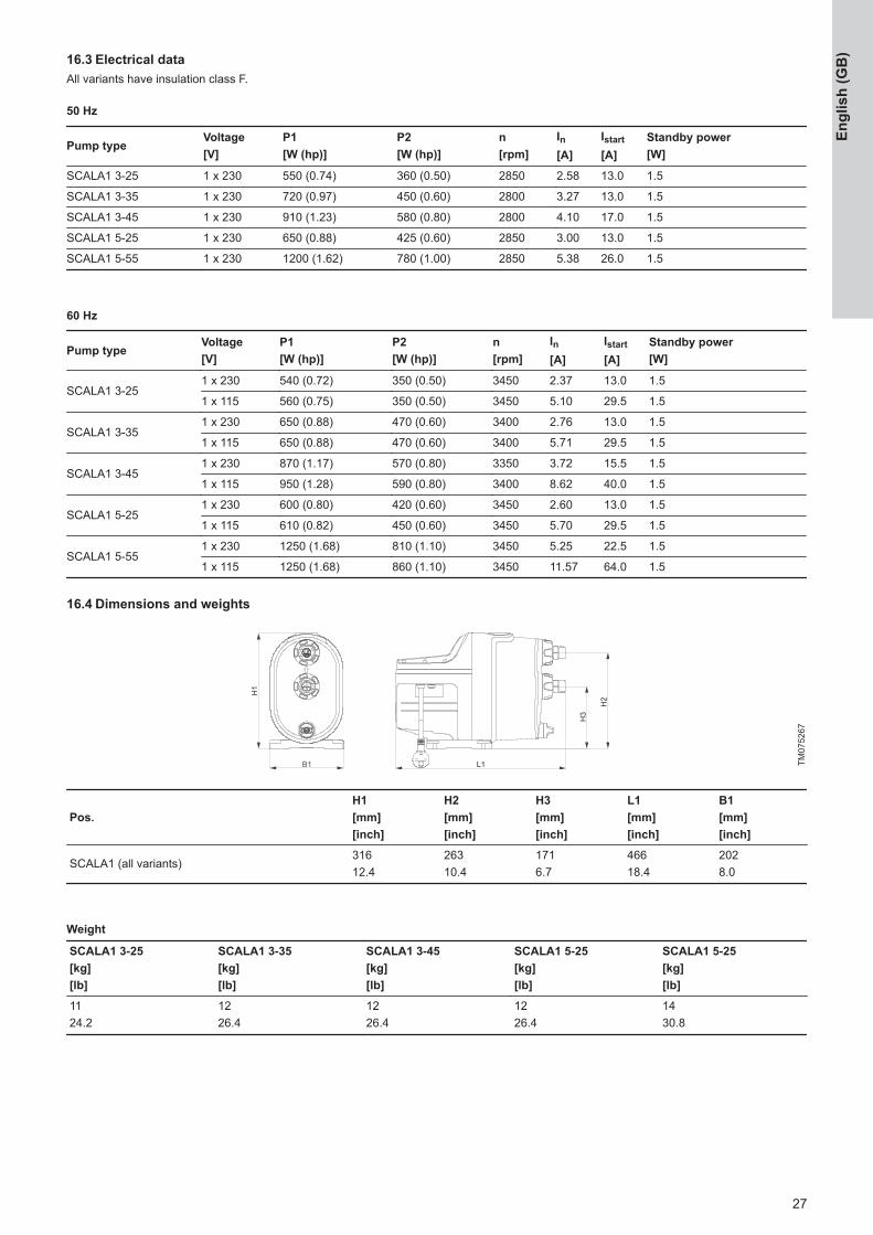
16.3 Electrical dataAll variants have insulation class F.
50 Hz
Pump typeVoltage[V]
P1[W (hp)]
P2[W (hp)]
n[rpm]
In[A]
Istart[A]
Standby power[W]
SCALA1 3-25 1 x 230 550 (0.74) 360 (0.50) 2850 2.58 13.0 1.5
SCALA1 3-35 1 x 230 720 (0.97) 450 (0.60) 2800 3.27 13.0 1.5
SCALA1 3-45 1 x 230 910 (1.23) 580 (0.80) 2800 4.10 17.0 1.5
SCALA1 5-25 1 x 230 650 (0.88) 425 (0.60) 2850 3.00 13.0 1.5
SCALA1 5-55 1 x 230 1200 (1.62) 780 (1.00) 2850 5.38 26.0 1.5
60 Hz
Pump typeVoltage[V]
P1[W (hp)]
P2[W (hp)]
n[rpm]
In[A]
Istart[A]
Standby power[W]
SCALA1 3-251 x 230 540 (0.72) 350 (0.50) 3450 2.37 13.0 1.5
1 x 115 560 (0.75) 350 (0.50) 3450 5.10 29.5 1.5
SCALA1 3-351 x 230 650 (0.88) 470 (0.60) 3400 2.76 13.0 1.5
1 x 115 650 (0.88) 470 (0.60) 3400 5.71 29.5 1.5
SCALA1 3-451 x 230 870 (1.17) 570 (0.80) 3350 3.72 15.5 1.5
1 x 115 950 (1.28) 590 (0.80) 3400 8.62 40.0 1.5
SCALA1 5-251 x 230 600 (0.80) 420 (0.60) 3450 2.60 13.0 1.5
1 x 115 610 (0.82) 450 (0.60) 3450 5.70 29.5 1.5
SCALA1 5-551 x 230 1250 (1.68) 810 (1.10) 3450 5.25 22.5 1.5
1 x 115 1250 (1.68) 860 (1.10) 3450 11.57 64.0 1.5
16.4 Dimensions and weights
TM07
5267
Pos.H1[mm][inch]
H2[mm][inch]
H3[mm][inch]
L1[mm][inch]
B1[mm][inch]
SCALA1 (all variants)31612.4
26310.4
1716.7
46618.4
2028.0
Weight
SCALA1 3-25[kg][lb]
SCALA1 3-35[kg][lb]
SCALA1 3-45[kg][lb]
SCALA1 5-25[kg][lb]
SCALA1 5-25[kg][lb]
1124.2
1226.4
1226.4
1226.4
1430.8
27
Engl
ish
(GB
)

16.5 Air handling mode performance curves
0.0 0.4 0.8 1.2 1.6 2.0 2.4 2.8 3.2 3.6 4.0 4.4 4.8 5.2 Q [m³/h]
0
4
8
12
16
20
24
28
H[m]
0 2 4 6 8 10 12 14 16 18 20 22 Q [US GPM]
0
20
40
60
80
[ft]H
SCALA1 3-25
Airhandling
0.0 0.4 0.8 1.2 1.6 2.0 2.4 2.8 3.2 3.6 4.0 4.4 4.8 5.2 Q [m³/h]
0
100
200
300
400
500
600[W]P1
0.0
0.2
0.4
0.6
0.8
[hp]P1
Airhandling
TM07
5233
0.0 0.4 0.8 1.2 1.6 2.0 2.4 2.8 3.2 3.6 4.0 4.4 4.8 5.2 Q [m³/h]
0
5
10
15
20
25
30
35
40
H[m]
0 2 4 6 8 10 12 14 16 18 20 22 Q [US GPM]
0
20
40
60
80
100
120
[ft]H
SCALA1 3-35
Airhandling
0.0 0.4 0.8 1.2 1.6 2.0 2.4 2.8 3.2 3.6 4.0 4.4 4.8 5.2 Q [m³/h]
0
200
400
600
800
[W]P1
0.0
0.2
0.4
0.6
0.8
1.0
[hp]P1
Airhandling
TM07
5234
0.0 0.5 1.0 1.5 2.0 2.5 3.0 3.5 4.0 4.5 5.0 Q [m³/h]
0
5
10
15
20
25
30
35
40
45
H[m]
0 2 4 6 8 10 12 14 16 18 20 22 Q [US GPM]
0
20
40
60
80
100
120
140
[ft]H
SCALA1 3-45
Airhandling
0.0 0.5 1.0 1.5 2.0 2.5 3.0 3.5 4.0 4.5 5.0 Q [m³/h]
0
200
400
600
800
1000
[W]P1
0.0
0.2
0.4
0.6
0.8
1.0
1.2
1.4[hp]P1
Airhandling
TM07
5235
0.0 0.5 1.0 1.5 2.0 2.5 3.0 3.5 4.0 4.5 5.0 5.5 6.0 Q [m³/h]
0
4
8
12
16
20
24
28
H[m]
0 2 4 6 8 10 12 14 16 18 20 22 24 26Q [US GPM]
0
20
40
60
80
[ft]H
SCALA1 5-25
Airhandling
0.0 0.5 1.0 1.5 2.0 2.5 3.0 3.5 4.0 4.5 5.0 5.5 6.0 Q [m³/h]
0
200
400
600
800
[W]P1
0.0
0.2
0.4
0.6
0.8
1.0
[hp]P1
Airhandling
TM07
5236
0.0 0.5 1.0 1.5 2.0 2.5 3.0 3.5 4.0 4.5 5.0 5.5 6.0 6.5 7.0 Q [m³/h]
0
5
10
15
20
25
30
35
40
45
50
55
H[m]
0 2 4 6 8 10 12 14 16 18 20 22 24 26 28 Q [US GPM]
0
20
40
60
80
100
120
140
160
180
[ft]H
SCALA1 5-55
Airhandling
0.0 0.5 1.0 1.5 2.0 2.5 3.0 3.5 4.0 4.5 5.0 5.5 6.0 6.5 7.0 Q [m³/h]
200
400
600
800
1000
1200
1400[W]P1
0.4
0.6
0.8
1.0
1.2
1.4
1.6
1.8
[hp]P1
Airhandling
TM07
5237
28
English (GB
)

17. Approvals
17.1 Bluetooth technology information
Frequency of operation 2400 – 2483.5 MHz (ISM band)
Modulation Type GFSK
Data Rate 1 Mbps
Transmit power 5 dBm EIRP with internalantenna
For Brazil only: This pump has a BLE ANT board equipped withBluetooth technology with these specifications.
17.2 FCC/ISED general requirements
0
0
0
0 0
FCC ID: OG3-SCALAIC: 10447A-SCALA
TM07
5015
FCC ID:OG3-SCALA1, IC:10447A-SCALA1
This device complies with FCC and ISED radiation exposure limitsset forth for an uncontrolled environment. This device must beinstalled and operated with a minimum distance of 20 cm (7.87inches) between the radiator and your body. This transmitter mustnot be co-located or operated in conjunction with any other antennaor transmitter.
FCC
This device complies with Part 15 of the FCC Rules.Operation is subject to the following two conditions:1. This device may not cause harmful interference, and2. This device must accept any interference received,
including interference that may cause undesiredoperation.
Changes or modifications made to this equipment notexpressly approved by Grundfos may void the user’sauthority to operate this equipment.
ISED
This device complies with ISED’s license-exempt RSSs.Operation is subject to the following two conditions: 1. This device may not cause harmful interference, and2. This device must accept any interference received,
including interference that may cause undesiredoperation.
Changes or modifications made to this equipment notexpressly approved by Grundfos may void the user’sauthority to operate this equipment.
This radio transmitter (IC:10447A-GIM1A) has been approved byISED to operate with Grundfos cellular module CIM 280-US(IC:10447A-CIM2X034G). Only the original Grundfos suppliedantenna, part no. 99838775, is permitted.This radio transmitter (IC:10447A-SCALA1) has been approved byISED to operate with the antenna integrated into the device. Otherantenna types are strictly prohibited for use with this device.The maximum antenna gain is:
CDMA850/LTE B5 +0.3 dBi (824-849 MHz)
CDMA1900/LTE B2 -1.2 dBi (1850-1910 MHz)
LTE B4 +1.5 dBi (1710-1755 MHz)
LTE B17 -7.0 dBi (704-716 MHz)
LTE B12 -7.0 dBi (698-716 MHz)
LTE B13 -5.0 dBi (777-787 MHz)
Bluetooth information
Frequency of operation 2400 - 2483.5 MHz (ISM band)
Modulation type GFSK
Data rate 1 Mbps
Transmit power 5 dBm EIRP with internalantenna
29
Engl
ish
(GB
)

18. Disposing of the productThis product or parts of it must be disposed of in an environmentallysound way.1. Use the public or private waste collection service.
2. If this is not possible, contact the nearest Grundfos company orservice workshop.
3. Dispose of the waste battery through the national collectiveschemes. If in doubt, contact your local Grundfos company.
The crossed-out wheelie bin symbol on a productmeans that it must be disposed of separately fromhousehold waste. When a product marked with thissymbol reaches its end of life, take it to a collectionpoint designated by the local waste disposalauthorities. The separate collection and recycling ofsuch products will help protect the environment andhuman health.
See also end-of-life information at www.grundfos.com/product-recycling.
18.1 Disposing of hazardous or toxic materialsWARNINGChemical hazard Death or serious personal injury ‐ Observe the material safety data sheet of the dosing
medium. ‐ Wear protective clothing when working on the dosing
head, connections or lines. ‐ Rinse the parts that have been in contact with the
dosing medium. ‐ Collect and dispose of all chemicals in a way that is
not harmful to persons or the environment.
The materials used in DMX pumps do not pose any health risk tothe person handling them. To identify the specific materials, checkthe type key on the product nameplate and read the explanation inthe section Type key.Observe also the product recycling page on http://www.grundfos.com/products/product-sustainability/dmx.html
30
English (GB
)
ArgentinaBombas GRUNDFOS de Argentina S.A.Ruta Panamericana km. 37.500industin1619 - Garín Pcia. de B.A.Tel.: +54-3327 414 444Fax: +54-3327 45 3190
AustraliaGRUNDFOS Pumps Pty. Ltd.P.O. Box 2040Regency ParkSouth Australia 5942Tel.: +61-8-8461-4611 Fax: +61-8-8340-0155
AustriaGRUNDFOS Pumpen Vertrieb Ges.m.b.H.Grundfosstraße 2A-5082 Grödig/SalzburgTel.: +43-6246-883-0Fax: +43-6246-883-30
BelgiumN.V. GRUNDFOS Bellux S.A.Boomsesteenweg 81-83B-2630 AartselaarTel.: +32-3-870 7300Fax: +32-3-870 7301
BelarusПредставительство ГРУНДФОС в Минске220125, Минскул. Шафарнянская, 11, оф. 56, БЦ «Порт»Тел.: +375 17 397 397 3 +375 17 397 397 4Факс: +375 17 397 397 1E-mail: [email protected]
Bosnia and HerzegovinaGRUNDFOS SarajevoZmaja od Bosne 7-7ABiH-71000 SarajevoTel.: +387 33 592 480Fax: +387 33 590 465www.ba.grundfos.com E-mail: [email protected]
BrazilBOMBAS GRUNDFOS DO BRASILAv. Humberto de Alencar Castelo Branco,630CEP 09850 - 300São Bernardo do Campo - SPTel.: +55-11 4393 5533Fax: +55-11 4343 5015
BulgariaGrundfos Bulgaria EOODSlatina DistrictIztochna Tangenta street no. 100BG - 1592 SofiaTel.: +359 2 49 22 200Fax: +359 2 49 22 201E-mail: [email protected]
CanadaGRUNDFOS Canada inc.2941 Brighton RoadOakville, OntarioL6H 6C9Tel.: +1-905 829 9533Fax: +1-905 829 9512
ChinaGRUNDFOS Pumps (Shanghai) Co. Ltd.10F The Hub, No. 33 Suhong RoadMinhang DistrictShanghai 201106 PRCTel.: +86 21 612 252 22 Fax: +86 21 612 253 33
ColumbiaGRUNDFOS Colombia S.A.S.Km 1.5 vía Siberia-Cota Conj. PotreroChico,Parque Empresarial Arcos de Cota Bod. 1A.Cota, CundinamarcaTel.: +57(1)-2913444Fax: +57(1)-8764586
CroatiaGRUNDFOS CROATIA d.o.o.Buzinski prilaz 38, BuzinHR-10010 ZagrebTel.: +385 1 6595 400Fax: +385 1 6595 499www.hr.grundfos.com
Czech RepublicGRUNDFOS Sales Czechia and Slovakias.r.o.Čajkovského 21779 00 OlomoucTel.: +420-585-716 111
DenmarkGRUNDFOS DK A/SMartin Bachs Vej 3DK-8850 BjerringbroTel.: +45-87 50 50 50Fax: +45-87 50 51 51E-mail: [email protected]/DK
EstoniaGRUNDFOS Pumps Eesti OÜPeterburi tee 92G11415 TallinnTel.: + 372 606 1690Fax: + 372 606 1691
FinlandOY GRUNDFOS Pumput ABTrukkikuja 1FI-01360 VantaaTel.: +358-(0) 207 889 500
FrancePompes GRUNDFOS Distribution S.A.Parc d’Activités de Chesnes57, rue de MalacombeF-38290 St. Quentin Fallavier (Lyon)Tel.: +33-4 74 82 15 15Fax: +33-4 74 94 10 51
GermanyGRUNDFOS GMBHSchlüterstr. 3340699 ErkrathTel.: +49-(0) 211 929 69-0Fax: +49-(0) 211 929 69-3799E-mail: [email protected] in Deutschland:[email protected]
GreeceGRUNDFOS Hellas A.E.B.E.20th km. Athinon-Markopoulou Av.P.O. Box 71GR-19002 PeaniaTel.: +0030-210-66 83 400Fax: +0030-210-66 46 273
Hong KongGRUNDFOS Pumps (Hong Kong) Ltd.Unit 1, Ground floor, Siu Wai industrialCentre29-33 Wing Hong Street & 68 King LamStreet, Cheung Sha WanKowloonTel.: +852-27861706 / 27861741Fax: +852-27858664
HungaryGRUNDFOS Hungária Kft.Tópark u. 8H-2045 TörökbálintTel.: +36-23 511 110Fax: +36-23 511 111
IndiaGRUNDFOS Pumps india Private Limited118 Old Mahabalipuram RoadThoraipakkamChennai 600 097Tel.: +91-44 2496 6800
IndonesiaPT GRUNDFOS PompaGraha intirub Lt. 2 & 3Jln. Cililitan Besar No.454. Makasar,Jakarta TimurID-Jakarta 13650Tel.: +62 21-469-51900Fax: +62 21-460 6910 / 460 6901
IrelandGRUNDFOS (Ireland) Ltd.Unit A, Merrywell Business ParkBallymount Road LowerDublin 12Tel.: +353-1-4089 800Fax: +353-1-4089 830
ItalyGRUNDFOS Pompe Italia S.r.l.Via Gran Sasso 4I-20060 Truccazzano (Milano)Tel.: +39-02-95838112Fax: +39-02-95309290 / 95838461
JapanGRUNDFOS Pumps K.K.1-2-3, Shin-Miyakoda, Kita-kuHamamatsu431-2103 JapanTel.: +81 53 428 4760Fax: +81 53 428 5005
KoreaGRUNDFOS Pumps Korea Ltd.6th Floor, Aju Building 679-5Yeoksam-dong, Kangnam-ku, 135-916Seoul, KoreaTel.: +82-2-5317 600Fax: +82-2-5633 725
LatviaSIA GRUNDFOS Pumps LatviaDeglava biznesa centrsAugusta Deglava ielā 60LV-1035, Rīga,Tel.: + 371 714 9640, 7 149 641Fax: + 371 914 9646
LithuaniaGRUNDFOS Pumps UABSmolensko g. 6LT-03201 VilniusTel.: + 370 52 395 430Fax: + 370 52 395 431
MalaysiaGRUNDFOS Pumps Sdn. Bhd.7 Jalan Peguam U1/25Glenmarie industrial Park40150 Shah Alam, SelangorTel.: +60-3-5569 2922Fax: +60-3-5569 2866
MexicoBombas GRUNDFOS de MéxicoS.A. de C.V.Boulevard TLC No. 15Parque industrial Stiva AeropuertoApodaca, N.L. 66600Tel.: +52-81-8144 4000Fax: +52-81-8144 4010
NetherlandsGRUNDFOS NetherlandsVeluwezoom 351326 AE AlmerePostbus 220151302 CA ALMERETel.: +31-88-478 6336Fax: +31-88-478 6332E-mail: [email protected]
New ZealandGRUNDFOS Pumps NZ Ltd.17 Beatrice Tinsley CrescentNorth Harbour Industrial EstateAlbany, AucklandTel.: +64-9-415 3240Fax: +64-9-415 3250
NorwayGRUNDFOS Pumper A/SStrømsveien 344Postboks 235, LeirdalN-1011 OsloTel.: +47-22 90 47 00Fax: +47-22 32 21 50
PolandGRUNDFOS Pompy Sp. z o.o.ul. Klonowa 23Baranowo k. PoznaniaPL-62-081 PrzeźmierowoTel.: (+48-61) 650 13 00Fax: (+48-61) 650 13 50
PortugalBombas GRUNDFOS Portugal, S.A.Rua Calvet de Magalhães, 241Apartado 1079P-2770-153 Paço de ArcosTel.: +351-21-440 76 00Fax: +351-21-440 76 90
RomaniaGRUNDFOS Pompe România SRLS-PARK BUSINESS CENTER, ClădireaA2, etaj 2Str. Tipografilor, Nr. 11-15, Sector 1, Cod013714Bucuresti, RomaniaTel.: 004 021 2004 100E-mail: [email protected]
RussiaООО Грундфос Россияул. Школьная, 39-41Москва, RU-109544, Russia Тел. (+7) 495 564-88-00 (495) 737-30-00Факс (+7) 495 564 8811E-mail [email protected]
SerbiaGrundfos Srbija d.o.o.Omladinskih brigada 90b11070 Novi BeogradTel.: +381 11 2258 740Fax: +381 11 2281 769www.rs.grundfos.com
SingaporeGRUNDFOS (Singapore) Pte. Ltd. 25 Jalan Tukang Singapore 619264Tel.: +65-6681 9688Faxax: +65-6681 9689
SlovakiaGRUNDFOS s.r.o.Prievozská 4D 821 09 BRATISLAVATel.: +421 2 5020 1426sk.grundfos.com
SloveniaGRUNDFOS LJUBLJANA, d.o.o.Leskoškova 9e, 1122 LjubljanaTel.: +386 (0) 1 568 06 10Fax: +386 (0)1 568 06 19E-mail: [email protected]
South AfricaGRUNDFOS (PTY) LTD16 Lascelles Drive, Meadowbrook Estate1609 Germiston, JohannesburgTel.: (+27) 10 248 6000Fax: (+27) 10 248 6002E-mail: [email protected]
SpainBombas GRUNDFOS España S.A.Camino de la Fuentecilla, s/n E-28110 Algete (Madrid)Tel.: +34-91-848 8800Fax: +34-91-628 0465
SwedenGRUNDFOS ABBox 333 (Lunnagårdsgatan 6)431 24 MölndalTel.: +46 31 332 23 000Fax: +46 31 331 94 60
SwitzerlandGRUNDFOS Pumpen AGBruggacherstrasse 10CH-8117 Fällanden/ZHTel.: +41-44-806 8111Fax: +41-44-806 8115
TaiwanGRUNDFOS Pumps (Taiwan) Ltd.7 Floor, 219 Min-Chuan RoadTaichung, Taiwan, R.O.C.Tel.: +886-4-2305 0868Fax: +886-4-2305 0878
ThailandGRUNDFOS (Thailand) Ltd.92 Chaloem Phrakiat Rama 9 RoadDokmai, Pravej, Bangkok 10250Tel.: +66-2-725 8999Fax: +66-2-725 8998
TurkeyGRUNDFOS POMPA San. ve Tic. Ltd. Sti.Gebze Organize Sanayi Bölgesi Ihsan dede Caddesi2. yol 200. Sokak No. 20441490 Gebze/ Kocaeli Tel.: +90 - 262-679 7979Fax: +90 - 262-679 7905E-mail: [email protected]
UkraineБізнес Центр ЄвропаСтоличне шосе, 103м. Київ, 03131, УкраїнаTel.: (+38 044) 237 04 00Fax: (+38 044) 237 04 01E-mail: [email protected]
United Arab EmiratesGRUNDFOS Gulf DistributionP.O. Box 16768Jebel Ali Free Zone, DubaiTel.: +971 4 8815 166Fax: +971 4 8815 136
United KingdomGRUNDFOS Pumps Ltd.Grovebury RoadLeighton Buzzard/Beds. LU7 4TLTel.: +44-1525-850000 Fax: +44-1525-850011
U.S.A.GRUNDFOS Water Utility Head QuartersBrookshire, Texas 77423 USA
UzbekistanGrundfos Tashkent, UzbekistanThe Representative Office of GrundfosKazakhstan in Uzbekistan38a, Oybek street, TashkentTel.: (+998) 71 150 3290 / 71 150 3291Fax: (+998) 71 150 3292
Revision InfoLast revised on 09-09-2020
Grundfos com
panies

99735528 04.2021ECM: 1312602 Tr
adem
arks
dis
play
ed in
this
mat
eria
l, in
clud
ing
but n
ot li
mite
d to
Gru
ndfo
s, th
e G
rund
fos
logo
and
“be
thin
k in
nova
te” a
re re
gist
ered
trad
emar
ks o
wne
d by
The
Gru
ndfo
s G
roup
. All
right
s re
serv
ed.
© 2
021
Gru
ndfo
s H
oldi
ng A
/S, a
ll rig
hts
rese
rved
.