sending and receiving data between mobile and data logger - diva
TRANSCRIPT
Sending and Receiving Data between Mobile and Data Logger
Nanda Kishore Abbaraju
ELECTRICAL ENGINEERING
Postadress: Besöksadress: Telefon:
Box 1026 Gjuterigatan 5 036-10 10 00 (vx) 551 11 Jönköping
Informationsutbyte/överföring från datalogger till mobiltelefon (via bluetooth)
Nanda Kishore Abbaraju
Detta examensarbete är utfört vid Tekniska Högskolan i Jönköping inom ämnesområdet elektroteknik. Arbetet är ett led i teknologie magisterutbildningen med inriktning inbyggda elektronik- och datorsystem. Författarna svarar själva för framförda åsikter, slutsatser och resultat.
Handledare: Joakim Staberg Examinator: Youzhi-Xu Omfattning: 20 poäng (D-nivå) Datum: Arkiveringsnummer:

i
Abstract
The goal of this project is to develop Mobile application using Bluetooth API
to communicate with Data Logger and to receive the data and display on the
screen. Special option should be created for the user to send the received data
to web server. Main issue of using Bluetooth is to replace cables and low cost.
The results show the temperature values for every received byte from Data
Logger on mobile screen. This thesis explains about Bluetooth, J2ME, java API
for Bluetooth and necessary infrastructure to develop mobile applications
using Bluetooth for communicating with Data Logger.

Sammanfattning
ii
Sammanfattning
Målet med detta examensarbete är att utveckla en mobil applikation där en
handburen enhet, i detta fall en mobiltelefon, använder ett Bluetooth API som
kommunicerar med en datalogger för att hämta temperaturdata och
visualisera på mobiltelefonens skärm. Från telefonen skall möjligheten finnas
att publicera informationen på en webbserver.
Orsaken till att Bluetooth används är dess möjligheter att skapa ett trådlöst
system till en låg kostnad. Informationen som visas på telefonens skärm är all
temperaturdata som hämtats från dataloggern vid ett tillfälle.
Examensarbetet behandlar; Bluetooth, J2ME, java, Bluetooth API och övriga
gränssnitt som krävs för att skapa denna typ av applikation.
Acknowledgements
iii
Acknowledgements
I find myself overwhelmed in offering my parents all my thanks in dedicating this
thesis to them.
First of all I would like to thank Joakim Staberg for giving me the opportunity to
work with this thesis. I would like to thank to my brother Praveen who has been a
great support all through this work. Also I would like to thank my parents
Satyanarayana and Kameswari for their patience, moral support and understanding
allowed me to complete this thesis.
Thanks to Joakim Staberg and Evgueni rabotchi who helped me all the time of this
thesis.
Thanks to all my friends who were far away from me, still providing me the
confidence, encouragement throughout the thesis.
To each of the above I extend my deepest appreciation. Thank you for all your
support and guidance.
Key words
iv
Key words
Data Logger, Bluetooth, MIDlet, J2ME, RFCOMM.

Contents
v
Contents
1 Introduction ................................................................................ 1
1.1 PURPOSE/OBJECTIVES ................................................................................................................. 3 1.2 THESIS OUTLINE .......................................................................................................................... 3
2 A brief introduction to Bluetooth ................................................. 4
2.1 BACKGROUND ............................................................................................................................. 4 2.2 BLUETOOTH ARCHITECTURE ....................................................................................................... 5 2.3 PICONET ...................................................................................................................................... 6 2.4 L2CAP (LOGICAL LINK CONTROL AND ADAPTATION PROTOCOL) LAYER .................................... 7 2.5 RFCOMM ..................................................................................................................................... 8 2.5.2 MULTIPLE EMULATED SERIAL PORTS ........................................................................................... 9 2.5.3 LIMITATIONS OF USING RFCOMM ............................................................................................ 10 2.5.4 CLIENT CONNECTIONS USING RFCOMM PROFILE ..................................................................... 10 2.6 DEVICE DISCOVERY ..................................................................................................................... 10 2.7 SERVICE DISCOVERY .................................................................................................................... 11 2.8 BLUETOOTH PROFILES .................................................................................................................. 12
3 Development tools .................................................................... 15
3.1 J2ME ........................................................................................................................................... 16 3.1.1 CONFIGURATIONS AND PROFILES ............................................................................................... 17 3.1.2 CONNECTED LIMITED DEVICE CONFIGURATION (CLDC) .......................................................... 17 3.3 MIDLET .................................................................................. ERROR! BOOKMARK OT DEFIED. 3.3.1 MIDLETS DEPLOYMENT ............................................................................................................. 21 3.3.2 LOCAL DEPLOYMENT ................................................................................................................. 21 3.3.3 REMOTE DEPLOYMENT .............................................................................................................. 21 3.3.4 OTA OVER THE AIR .................................................................................................................... 22
4 Implementation ........................................................................ 22
4.1 SOFTWARE TOOL ........................................................................................................................... 22 4.2 DATALOGGER ARCHITECTURE ....................................................................................................... 23 4.3 SMARTPHONES .............................................................................................................................. 23 4.4 SENDING DATA TO WEB SERVER FROM MIDLETS ......................................................................... 37
5 Demonstration and some test results ............................................ 38
5.1 DEMOSTRATION ............................................................................................................................ 38 5.2 NETWORKING DISTANCE ............................................................................................................... 40 5.3 CO-CHANNEL INTERFERENCE ....................................................................................................... 43
6 Conclusion and discussions ...................................................... 45
References ...................................................................................... 46
Appendix 1 ...................................................................................... 47
Appendix 2 ...................................................................................... 48
List of Figures
vi
List of Figures
Figure 1.1 System construction and scenario of applications
Figure 2.1 Bluetooth protocol stack
Figure2.2 Pico net
Figure 2.3 Scatter net
Figure 2.4 L2CAP with protocol layers
Figure 2.5 RFCOMM Reference model
Figure 2.6 Multi Emulated serial Ports
Figure 3.1 Shows the J2ME architecture
Figure 3.2 CLDC position in J2ME architecture
Figure 3.3 Midlet architecture overview
Figure 3.4 Message Frame
Figure 4.1 Nokia N73
Figure 4.2 Screen displaying menu buttons
Figure 4.3 Mobile screen displaying stop command.
Figure 4.4 Screen displaying discovered devices
Figure 4.5 Waiting for permission to requests from Data Logger
Figure 4.6 Receiving communication connect with Data logger
Figure 4.7 Message Frame
Figure 4.8 Sequence diagram for communicating with data logger.
Figure 4.9 Screen displaying no of bytes Received from data logger
Figure 4.10 Mobile screen displaying permission to Temperature
Figure 4.11 Waiting for user connect to web server.
Figure 5.1 Received data from Data Logger
Table 2.1 List of Bluetooth Profiles
Table 4.1 List of mobile manufactures providing Bluetooth facality Table 4.2 Requests and Feedbacks of Data logger
Table 5.1 Temperature values after converting input readout bytes
Table 5.2 Results when Data Logger is placed in box.
Table 5.3 Results when Data Logger placed in Fridge.
Table 5.4 Results when Data Logger placed in open environment.

List of Abbreviations
vii
List of Abbreviations
CLDC Connected Limited Device Configuration
GCF Generic Connection Framework
J2ME Java 2 Micro Edition
L2CAP Logical Link Control and Adaption Protocol
MIDP Mobile Information Device Profile
SDDB Service Discovery Database
GAP Generic Access Profile
JABWT Java APIs for Bluetooth Wireless Technology
MID Mobile Information Device
RFCOMM Radio Frequency Communication
SPP Serial Port Profile
SDP Service Discovery Protocol
UUID Universally Unique Identifier
WTKs Wireless Toolkits
HCL Host controller interface

introduction
1
1 Introduction
Wireless technologies are more popular in the world. Consumers are attracted
towards the wireless technologies. Day by day new wireless technologies are in the
market. For the period of the last few years the IEEE 802.11 technologies have in
progress to spread rapidly. The Bluetooth wireless technology is also spreading
quickly.
Bluetooth chipsets are mostly used in mobile devices. Bluetooth technology is
spreading rapidly due to general needs of mobile phones. Concurrent exchange of data
can be done using Bluetooth. Bluetooth does away with wired cabled connections
such as serial, parallel, and USB. Bluetooth was developed for small data transfers
and for voice communications. This makes it an excellent for using in peripherals
devices such as wireless microphones, headsets, mice, keyboards and mobile
handsets.
Wi-Fi was generally developed to transmit large amounts of data. There are so many
ways were Bluetooth is used to enhance our daily lives. It is used for entertainment
value of playing games head to head in multiplayer.
Java enabled mobile phones have previously been on the market for a few years. Few years ago java Application are not very sophisticated in the market. In software and
hardware industry, games are playing major role in the development of both hardware
and software due to this java games are targeting mobile devices.
Applications running on the Java platform access Bluetooth through the Java APIs for
Bluetooth Wireless Technology. As more Bluetooth-enabled devices enter into the
market, we can expect to see greater support for Java-based Bluetooth programming.
The J2ME Wireless Toolkit [8] supports JSR 82 which makes Bluetooth development
and testing much simpler. The toolkit not only includes the necessary APIs to compile
programs, it also lets us to test Bluetooth functionality without Bluetooth hardware.
Motivation of the project is to develop communication system to send and
receive data without wires. As Bluetooth is a wireless communication
technology and majority of Bluetooth chips are using in cell phones this
master thesis uses Bluetooth enabled cell phones to communicate with Data
Logger.
My main contribution in this project is to develop mobile application using
Bluetooth to communicate with Data Logger and receive data from Data
Logger and display it on screen and also to send the received data to web
server.
Introduction
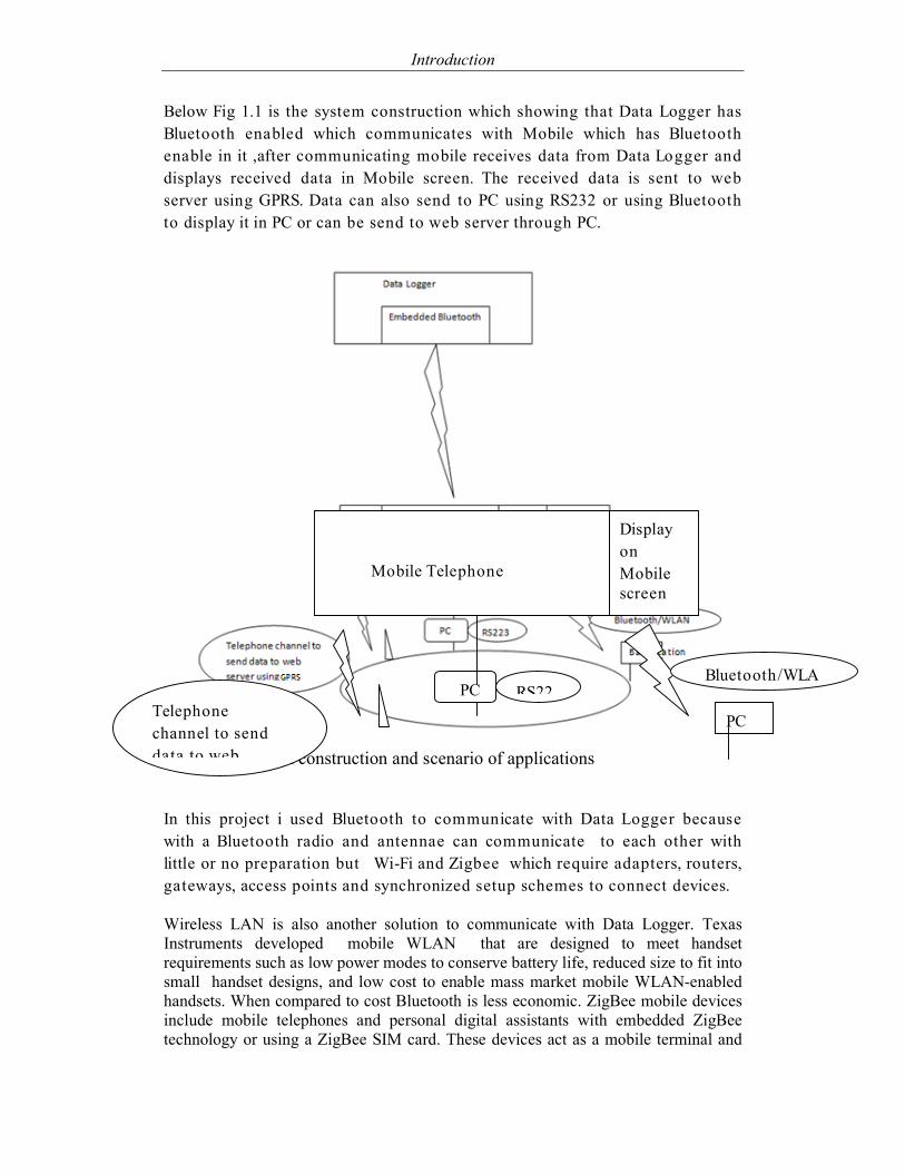
Below Fig 1.1 is the system construction which showing that Data Logger has
Bluetooth enabled which communicates with Mobile which has Bluetooth
enable in it ,after communicating mobile receives data from Data Logger and
displays received data in Mobile screen. The received data is sent to web
server using GPRS. Data can also send to PC using RS232 or using Bluetooth
to display it in PC or can be send to web server through PC.
Figure 1.1 System construction and scenario of applications
In this project i used Bluetooth to communicate with Data Logger because
with a Bluetooth radio and antennae can communicate to each other with
little or no preparation but Wi-Fi and Zigbee which require adapters, routers,
gateways, access points and synchronized setup schemes to connect devices.
Wireless LAN is also another solution to communicate with Data Logger. Texas
Instruments developed mobile WLAN that are designed to meet handset
requirements such as low power modes to conserve battery life, reduced size to fit into
small handset designs, and low cost to enable mass market mobile WLAN-enabled
handsets. When compared to cost Bluetooth is less economic. ZigBee mobile devices
include mobile telephones and personal digital assistants with embedded ZigBee
technology or using a ZigBee SIM card. These devices act as a mobile terminal and
PC
PC RS22Telephone
channel to send
data to web
Bluetooth/WLA
Display
on
Mobile
screen
Embedded
Bluetooth
Mobile Telephone

Introduction
3
as a sensor control device everyplace there is a ZigBee network or ZigBee access
point. Peer-to-Peer Small Data Sharing is available in ZigBee. Small files such as ring
tones, images, address book contacts can be shared easily between two ZigBee-
enabled mobile devices
1.1 Purpose/Objectives
The main objective of the project is to develop Bluetooth application for
mobile devices to communicate with Data Logger and receive data. The data
received should be displayed on screen and special option should be created
to send the received data from Data Logger in mobile to web server.
1.2 Thesis outline
Chapter 2 describes the theoretical background about the Bluetooth. Chapter
3 gives you brief description about J2ME and API’s which I used to develop
mobile application. Chapter 4 describes about implementation of sending and
receiving data between mobile and Data Logger and demonstrates the
complete procedure for getting the output. Chapter 5 shows the results and
chapter 6 follows conclusions from the results obtained.
4
2 A brief introduction to Bluetooth
2.1 Background
Bluetooth is a wireless communication protocol which is use for short
distances and in low power consumption devices. Bluetooth can be used to
communicate to two are more other Bluetooth capable devices. Bluetooth is
like any other communication protocol that we use every day like HTTP, FTP,
SMTP, or IMAP. Bluetooth is also like these protocols in that it has client-
server architecture. In Bluetooth the one who initiates the connection is the
master, and the ones who receive the connection are the slaves.
It was developed by the Swedish phone maker Ericsson in 1994. Bluetooth
communications operate in an unlicensed ISM band at 2.4 GHZ. Bluetooth is
capable of communicating up to 30 feet at 1 Mb/s in an Omni-directional
manner. It works like a radio. Bluetooth is far better to infrared because
infrared requires a distance of a few feet or less and requires a line of sight for
transmissions.
Bluetooth and 802.11b is created for two different goals. These both
technologies operate in same frequency band: 2.4GHz. The goal of wireless
LAN (802.11b) is to connect to two relatively large devices that have large of
power at high speeds. Wireless LAN (802.11b) is used to connect two laptops
within 300 feet at 11 Mb/s. Bluetooth is developed to connect smaller devices
like PDAs and mobile phones. Bluetooth is also intended to be used as cable
replacement technology. It is great to connect two PCs at moderate speed.
The Bluetooth standard was published by an industry known as the Bluetooth
SIG (special interest group). SIG is responsible for expansion of Bluetooth
standards .Sony Ericsson, Intel, IBM, Toshiba, Nokia, Microsoft, 3COM, and
Motorola are some of the companies involved in the SIG. Microsoft supports
Bluetooth in their Microsoft Windows Operating System (OS), hence,
Bluetooth software is made available to the vast majority of the desktop
software market. Both Nokia and Sony Ericsson consist of Bluetooth
technology in their latest cell phones.
Bluetooth supports list of application like audio, graphics, and video. For
example, audio devices can contain headsets, cordless and standard phones,
home stereos, and digital MP3 players.
5
2.2 Bluetooth architecture
Bluetooth is define as a layered protocol architecture consisting of core
protocols, cable replacement and telephony control protocols, and adopted
protocols. Bluetooth is both a hardware-based radio system and a software
stack that specifies the linkage between layers. The heart of the Bluetooth
specification is the Bluetooth protocol stack.
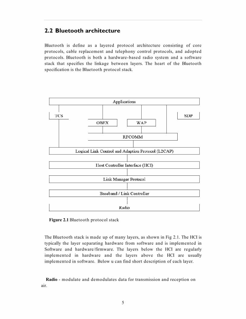
Figure 2.1 Bluetooth protocol stack
The Bluetooth stack is made up of many layers, as shown in Fig 2.1. The HCI is
typically the layer separating hardware from software and is implemented in
Software and hardware/firmware. The layers below the HCI are regularly
implemented in hardware and the layers above the HCI are usually
implemented in software. Below u can find short description of each layer.
Radio - modulate and demodulates data for transmission and reception on
air.
6
Baseband - Concerned with connection establishment within a pioneer,
addressing, packet format, timing, and power control.
Link manager protocol (LMP) Handles communication between and the
Bluetooth
module
2.3 Piconet
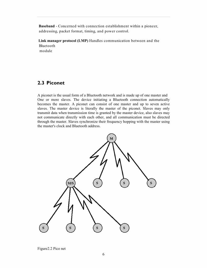
A piconet is the usual form of a Bluetooth network and is made up of one master and
One or more slaves. The device initiating a Bluetooth connection automatically
becomes the master. A piconet can consist of one master and up to seven active
slaves. The master device is literally the master of the piconet. Slaves may only
transmit data when transmission time is granted by the master device, also slaves may
not communicate directly with each other, and all communication must be directed
through the master. Slaves synchronize their frequency hopping with the master using
the master's clock and Bluetooth address.
Figure2.2 Pico net
7
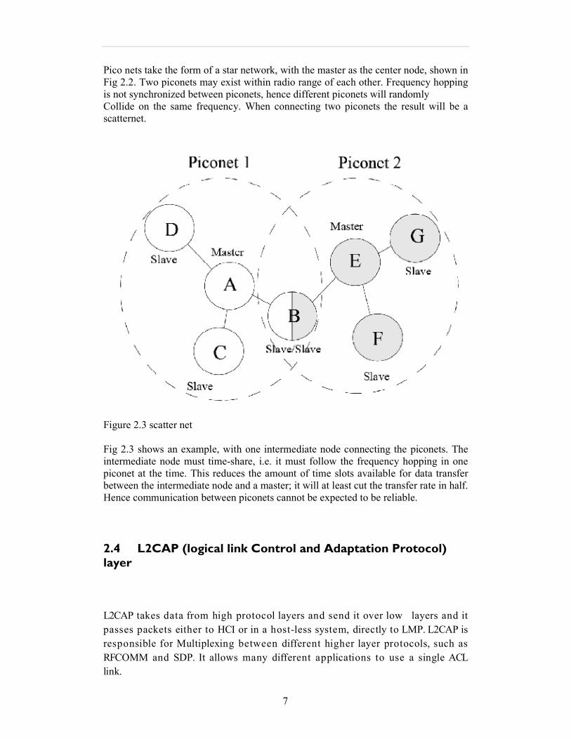
Pico nets take the form of a star network, with the master as the center node, shown in
Fig 2.2. Two piconets may exist within radio range of each other. Frequency hopping
is not synchronized between piconets, hence different piconets will randomly
Collide on the same frequency. When connecting two piconets the result will be a
scatternet.
Figure 2.3 scatter net
Fig 2.3 shows an example, with one intermediate node connecting the piconets. The
intermediate node must time-share, i.e. it must follow the frequency hopping in one
piconet at the time. This reduces the amount of time slots available for data transfer
between the intermediate node and a master; it will at least cut the transfer rate in half.
Hence communication between piconets cannot be expected to be reliable.
2.4 L2CAP (logical link Control and Adaptation Protocol) layer
L2CAP takes data from high protocol layers and send it over low layers and it
passes packets either to HCI or in a host-less system, directly to LMP. L2CAP is
responsible for Multiplexing between different higher layer protocols, such as
RFCOMM and SDP. It allows many different applications to use a single ACL
link.
8
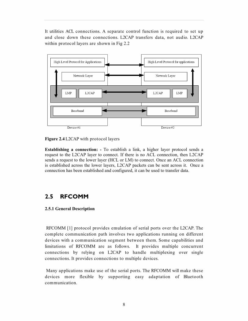
It utilities ACL connections. A separate control function is required to set up
and close down these connections. L2CAP transfers data, not audio. L2CAP
within protocol layers are shown in Fig 2.2
Figure 2.4 L2CAP with protocol layers
Establishing a connection: - To establish a link, a higher layer protocol sends a
request to the L2CAP layer to connect. If there is no ACL connection, then L2CAP
sends a request to the lower layer (HCL or LM) to connect. Once an ACL connection
is established across the lower layers, L2CAP packets can be sent across it. Once a
connection has been established and configured, it can be used to transfer data.
2.5 RFCOMM
2.5.1 General Description
RFCOMM [1] protocol provides emulation of serial ports over the L2CAP. The
complete communication path involves two applications running on different
devices with a communication segment between them. Some capabilities and
limitations of RFCOMM are as follows. It provides multiple concurrent
connections by relying on L2CAP to handle multiplexing over single
connections. It provides connections to multiple devices.
Many applications make use of the serial ports. The RFCOMM will make these
devices more flexible by supporting easy adaptation of Bluetooth
communication.

9
RFCOMM supports both direct communications between devices, acting as
endpoints, and device modem device communication. The RFCOMM also has built in
system for null modem emulation. In ordinary serial communication a baud rate is set.
This will not affect the actual throughput in the RFCOMM. However, if either device
is a modem type device or if data paring is done above the RFCOMM service
interface, the actual throughput will reflect the baud rate setting.
The RFCOMM layer is using the L2CAP layer, which provides flow control
mechanism. Therefore it is not necessary for the RFCOMM port to perform the flow
Control mechanism requested by the application.
Figure 2.5 RFCOMM Reference model
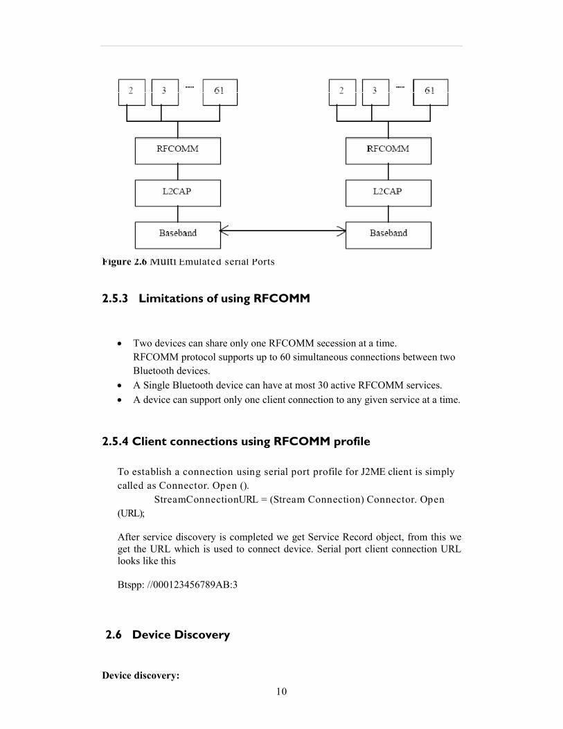
2.5.2 Multiple Emulated Serial Ports
The RFCOMM layer can handle up to 60 emulated ports. Two Bluetooth units using
RFCOMM in their communication may open multiple emulated serial ports. These
emulated serial ports are multiplexed together by the RFCOMM layer.
10
Figure 2.6 Multi Emulated serial Ports
2.5.3 Limitations of using RFCOMM
• Two devices can share only one RFCOMM secession at a time.
RFCOMM protocol supports up to 60 simultaneous connections between two
Bluetooth devices.
• A Single Bluetooth device can have at most 30 active RFCOMM services.
• A device can support only one client connection to any given service at a time.
2.5.4 Client connections using RFCOMM profile
To establish a connection using serial port profile for J2ME client is simply
called as Connector. Open ().
StreamConnectionURL = (Stream Connection) Connector. Open
(URL);
After service discovery is completed we get Service Record object, from this we
get the URL which is used to connect device. Serial port client connection URL
looks like this
Btspp: //000123456789AB:3
2.6 Device Discovery
Device discovery:

11
There are various factors affecting the Bluetooth device discovery time
1) As per the Bluetooth specifications [13], the device takes at least 10.24 seconds
for discovery.
2) In an error-prone environment, it is difficult to determine the maximum time
required for device discovery.
3) The device discovery time exceeds even more than normal when the two devices
are actively moving.
Device discovery is the first step which is used to discover nearby devices.
When we have discovered nearby devices we can find out which services they
offer. Discovery Agent and start inquiry method put the device into discovery
mode. To use the Bluetooth related method first we need to get reference to
local object by calling LocalDevice.getLocalDevice ().
Local Device object is used to obtain Discovery Agent object. Discovery Agent
object is used for Device Discovery and Service Discovery. When inquiry is
completed or canceled DiscoveryListener.INQUIRY_COMPLETED is invoked.
2.7 Service Discovery
Service Discovery:
Once the local device has found at least one remote device we can begin
searching services on the device of interest. The following services are
provided in java Bluetooth specification for service discovery. Discovery Agent,
Discovery Listener, Service Record, Data Element, and UUID [3]. Discovery
Agent provides methods to discover services on a Bluetooth server device,
and to initiate service –discover transactions.
In order to find services on remote devices either select Service () or search
Services () is used
Int transid= agent.searchServices (attributes, uuids, remoteDevice, this)
This is used to search services on a single remote Bluetooth device.
RemoteDevice is the reference to the reference to the remote device that we
want to search for services.
Public void device Discovered (RemoteDevice remote Device, Device Class
cod)

12
This method is called when a remote Bluetooth device is found from an
inquiry. The RemoteDevice object is a reference to the Bluetooth device found
from the inquiry.
Public void services Discovered (int transID, Service Record [] service
Record)
This method is called by the JVM when the services are discovered on the
remote device. The Trans ID and array of service Record are provided to this
method. Service Record object is used to get connectional of the remote
device.
2.8 Bluetooth profiles
Code Version Profile Name
GAP
1.1 Generic Access Profile
SDAP 1.1 Service Discovery Application Profile
CTP 1.1 Cordless Telephony Profile
IP 1.1 Intercom Profile
SPP
1.1 Serial Port Profile
HS 1.1 Headset Profile
DNP 1.1 Dial-up Networking Profile
FP 1.1 Fax Profile
LAP
1.1 LAN (Local Area Network) Access
Profile
GOEP 1.1 Generic Object Exchange Profile
OPP 1.1 Object Push Profile
FTP 1.1 File Transfer Profile
SP 1.1 Synchronization Profile
Table 2.1 List of Bluetooth Profiles
Generic Access Profile
The generic access profile defines the general procedures involved in discovery
devices and link management aspects of connecting to Bluetooth devices. It uses
features of the RFCOMM, L2CAP, Link Manager and Link Controller layers of the
Bluetooth stack.
Behaviors in standby and connection states are defined in the generic access profiles
to assure that connection always can be established. This profile describes how lower
layers are used along with higher layers.
13
Service Discovery Application Profile
The service discovery application profile defines the features and procedures for an
application in a Bluetooth device to discover and retrieve information about services
Located in other Bluetooth devices.
It defines the protocols and procedures that shall be used by a service discovery
application on a device to locate services in other Bluetooth-enabled devices by using
the Bluetooth Service Discovery Protocol (SDP).
Cordless Telephony Profile
The cordless telephony profile defines how a mobile phone could used to access fixed
network telephony service via a base station. This profile is used for wireless
telephony at home or at small offices. The profile includes making calls via the base
station, making direct intercom calls between two terminals, and accessing
supplementary external networks.
Intercom Profile
The intercom profile defines uses of mobile phones who establish direct speech links
between two devices. The direct link is established using telephony signaling over
Bluetooth. Mobile phones using direct links function as walkie-talkies.
Serial Port Profile
The serial port profile defines the requirements for Bluetooth devices necessary for
setting up emulated serial cable connection using RFCOMM between two peer
devices. This profile requires support for one-slot packets only. This means that data
rates up to 128 kbps can be used. Support for higher rates is optional. RFCOMM is
used to transport the user data, modem control signals and configuration commands.
Headset Profile
The headset profile defines the requirements for Bluetooth devices necessary to
support the headset use case. In the headset use case the headset can be used as the
Dial-up etworking Profile
The dial-up networking profile defines the protocols and procedures that should be
used by devices implementing the usage model called Internet Bridge. This profile is
used when a cellular phone or modem is used as a wireless modem.
Fax Profile
The fax profile defines the protocols and procedures that should be used by devices
implementing the fax usage model. In the profile a cellular phone may be used as a
wireless fax.
14
LA Access Profile
The LAN access profile defines local area network access using the point-to-point
protocol, PPP, over RFCOMM. PPP is widely used to allow access to networks
supporting various networking protocols. The profile supports LAN access for a
single Bluetooth device, LAN access for multiple Bluetooth devices, and PC to PC
(using PPP networking over serial cable emulation).
Generic Object Exchange Profile
The Generic Object Exchange Profile provides the functionality needed to use the
Object Exchange (OBEX) Protocol over Bluetooth. It is used by Object push profile,
File transfer profile, synchronization profile. The profile defines methods for object
exchange.
Object Push Profile
The object push profile defines protocols and procedures used in the object push
usage model. The profile uses the generic object exchange profile. In the object push
usage model there are procedures to push an object to the inbox of another Bluetooth
device, to pull an object from another Bluetooth device, and to exchange objects with
another Bluetooth device. The object exchanged can e.g. be a business card.
File Transfer Profile
The file transfer profile defines protocols and procedures used in the file transfer
usage model. The profile uses the generic object exchange profile. In the file transfer
usage model there are procedures to browse an object store of another Bluetooth
device, transfer objects between two Bluetooth devices, and to manipulate objects on
another Bluetooth device. Objects could be files and folders on an object store like a
file system.
Synchronization Profile
The synchronization profile defines protocols and procedures used in the
synchronization usage model. The profile uses the generic object exchange profile.
The usage model supports exchanges of information, e.g. to synchronize calendars on
different devices.
15
3 Development tools
This chapter gives an overview of the J2ME technology. The J2ME architecture is
Described in general before the components in the J2ME technology are introduced.
J2ME applications are also discussed in general, and it is explained how they are
Made available to end users.
16
J2ME is designed for devices with limited memory, display, and processing
power including cellular phones, PDAs, and pagers. Core J2ME Technology &
MIDP covers everything to develop powerful applications for this rapidly
expanding wireless market.
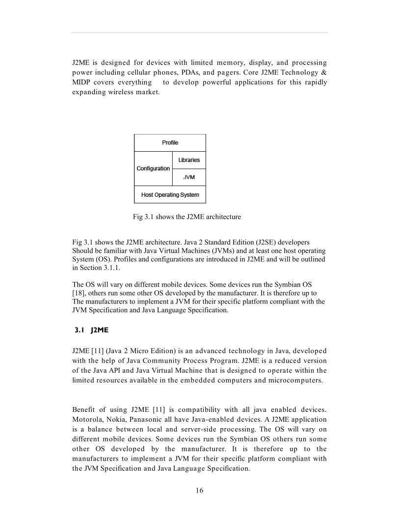
Fig 3.1 shows the J2ME architecture
Fig 3.1 shows the J2ME architecture. Java 2 Standard Edition (J2SE) developers
Should be familiar with Java Virtual Machines (JVMs) and at least one host operating
System (OS). Profiles and configurations are introduced in J2ME and will be outlined
in Section 3.1.1.
The OS will vary on different mobile devices. Some devices run the Symbian OS
[18], others run some other OS developed by the manufacturer. It is therefore up to
The manufacturers to implement a JVM for their specific platform compliant with the
JVM Specification and Java Language Specification.
3.1 J2ME
J2ME [11] (Java 2 Micro Edition) is an advanced technology in Java, developed
with the help of Java Community Process Program. J2ME is a reduced version
of the Java API and Java Virtual Machine that is designed to operate within the
limited resources available in the embedded computers and microcomputers.
Benefit of using J2ME [11] is compatibility with all java enabled devices.
Motorola, Nokia, Panasonic all have Java-enabled devices. A J2ME application
is a balance between local and server-side processing. The OS will vary on
different mobile devices. Some devices run the Symbian OS others run some
other OS developed by the manufacturer. It is therefore up to the
manufacturers to implement a JVM for their specific platform compliant with
the JVM Specification and Java Language Specification.
17
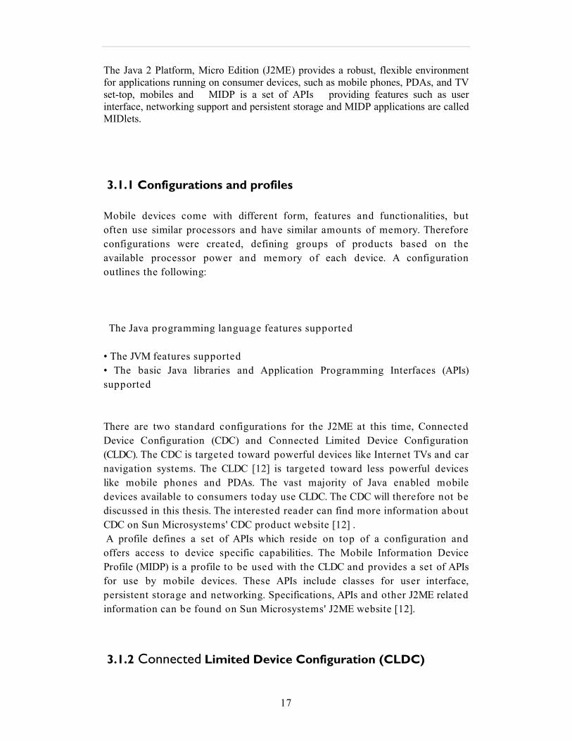
The Java 2 Platform, Micro Edition (J2ME) provides a robust, flexible environment
for applications running on consumer devices, such as mobile phones, PDAs, and TV
set-top, mobiles and MIDP is a set of APIs providing features such as user
interface, networking support and persistent storage and MIDP applications are called
MIDlets.
3.1.1 Configurations and profiles
Mobile devices come with different form, features and functionalities, but
often use similar processors and have similar amounts of memory. Therefore
configurations were created, defining groups of products based on the
available processor power and memory of each device. A configuration
outlines the following:
The Java programming language features supported
• The JVM features supported
• The basic Java libraries and Application Programming Interfaces (APIs)
supported
There are two standard configurations for the J2ME at this time, Connected
Device Configuration (CDC) and Connected Limited Device Configuration
(CLDC). The CDC is targeted toward powerful devices like Internet TVs and car
navigation systems. The CLDC [12] is targeted toward less powerful devices
like mobile phones and PDAs. The vast majority of Java enabled mobile
devices available to consumers today use CLDC. The CDC will therefore not be
discussed in this thesis. The interested reader can find more information about
CDC on Sun Microsystems' CDC product website [12] .
A profile defines a set of APIs which reside on top of a configuration and
offers access to device specific capabilities. The Mobile Information Device
Profile (MIDP) is a profile to be used with the CLDC and provides a set of APIs
for use by mobile devices. These APIs include classes for user interface,
persistent storage and networking. Specifications, APIs and other J2ME related
information can be found on Sun Microsystems' J2ME website [12].
3.1.2 Connected Limited Device Configuration (CLDC)
18
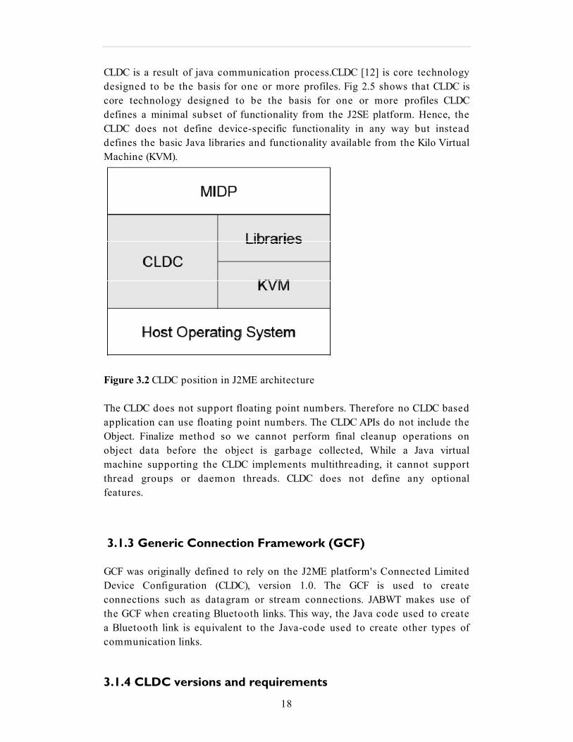
CLDC is a result of java communication process.CLDC [12] is core technology
designed to be the basis for one or more profiles. Fig 2.5 shows that CLDC is
core technology designed to be the basis for one or more profiles CLDC
defines a minimal subset of functionality from the J2SE platform. Hence, the
CLDC does not define device-specific functionality in any way but instead
defines the basic Java libraries and functionality available from the Kilo Virtual
Machine (KVM).
Figure 3.2 CLDC position in J2ME architecture
The CLDC does not support floating point numbers. Therefore no CLDC based
application can use floating point numbers. The CLDC APIs do not include the
Object. Finalize method so we cannot perform final cleanup operations on
object data before the object is garbage collected, While a Java virtual
machine supporting the CLDC implements multithreading, it cannot support
thread groups or daemon threads. CLDC does not define any optional
features.
3.1.3 Generic Connection Framework (GCF)
GCF was originally defined to rely on the J2ME platform's Connected Limited
Device Configuration (CLDC), version 1.0. The GCF is used to create
connections such as datagram or stream connections. JABWT makes use of
the GCF when creating Bluetooth links. This way, the Java code used to create
a Bluetooth link is equivalent to the Java-code used to create other types of
communication links.
3.1.4 CLDC versions and requirements

19
Two versions of the CLDC have been defined, version 1.0 and version 1.1.
CLDC 1.1 adds a few new features over CLDC 1.0. Floating point support is the
most important feature added. Several minor bug fixes have also been added.
CLDC 1.1 is intended to be backwards compatible with version 1.0. The
minimum memory requirement has been raised from 160 KB in version 1.0 to
192 KB in version 1.1 due to the added floating point support.
3.2 MIDP 2.0 (JSR 118)
MIDP 2.0 is a revised version of the MIDP 1.0 specification. MIDP 2.0 includes
new features such as an enhanced user interface, multimedia and game
functionality, greater connectivity, over-the-air (OTA) provisioning, and end-
to-end security. MIDP 2.0 is backward compatible with MIDP 1.0.
MIDP 2.0 provides greater extensibility. In the course of the ABB Media
support has been added. ABB enables developers the ability to add tones,
tone sequences and WAV files even if the Mobile Media API (MMAPI) optional
package is not available.
Game API is added in MIDP 2.0 which provides standard foundation for
building game. MIDP game API includes game-specific functionality which
provides greater control over graphics and performance.
MIDP 2.0 adds support connectivity standards outside HTTP, such as HTTPS,
datagram, sockets, server sockets, and serial port communication.
When the device receives information from server, push registry makes
possible to activate the midlet. Using carrier networks we can develop even
driven applications.
MIDP 2.0 has the ability to deploy and update applications over the air (OTA).
The MIDP specification defines how MIDlet suites are discovered, installed,
updated and removed on mobile information devices. MIDP allow a service
provider to discover which MIDlet suites will work on a given device, and we
can get status reports from the device following installation, updates or
removal.
HTTPS and SSL/TLS protocol provides end-to-end security access over the IP
(Internet Protocol) network. The ability to set up secure connections is a
increase advance for MIDP programming. A wide range of application models
require encryption of data and may now utilize the security model of MIDP 2.0
based on open standards.

20
3.3 MIDlet
The Mobile Information Device Profile (MIDP) is a set of Java APIs targeted at
mobile information devices such as mobile phones and entry-level palmtop
devices. A MIDlet is a MIDP application. Midlet architecture overview is shown
in Fig 2.6
Figure 3.3 Midlet architecture overview
MIDlets are usually available through MIDlet suites. A MIDlet suite consists of
two files, a .jar and a .jad file. The Java ARchive (JAR) file contains compiled
classes in a compressed and preverified format. Several MIDlets may be
included in a MIDlet suite. Hence, the JAR file will contain all these MIDlet
classes. This enables multiple MIDlets to share resources, like common
libraries included in the MIDlet suite or data stored on the device. Because of
security constraints, a MIDlet may only access the resources associated with its
own MIDlet suite. This applies to all resources, such as libraries it may depend
on or data stored on the MID.
The Java Application Descriptor (JAD) file is a plain text file containing
information About a MIDlet suite.

21
3.3.1 MIDlets Deployment
To deploy MIDlet into mobile first generate JAD, JAR files using WTK.These
JAD, JAR files should be deployed in mobile. This can be done in three ways.
We can deploy MIDlets remotely and locally as well we can download
MIDlets referenced by URLs over the air and on Java™ 2 Platform, Micro
Edition (J2ME)-enabled devices.
• Remote deployment. Remotely deploy a MIDlet developed on the local
desktop.
• Local deployment. Download a MIDlet developed on the local desktop to the
J2ME-enabled device connected to it.
• Downloading a MIDlet referenced by a URL on a J2ME-enabled device.
• Downloading a MIDlet referenced by a URL over the air (OTA).
3.3.2 Local Deployment
If we have J2ME mobile phone ,we can download java applicaton loader (JAL)
from the manufacture web site. Connect the phone to the computer using a
data cable Locate JAD and JAR files and click download button from the JAL
to upload the application into the cell phone. Browse the application on the
cell to the place where we just downloaded. If we click on that application we
get install application option click yes to install.
3.3.3 Remote Deployment
In remote deployment first upload JAD and JAR files to web server .Change
theJAD files’s MIDlet –JAR-URL property to the URL of the JAR file. To test
weather the application deployed correctely or not open computer browser
and enter the URL of the JAD file.The WTKs default emulator should appear
and the application should run in it .

22
3.3.4 OTA over the air
OTA is one more type deployment of MIDlet’s from internet to wireless
devices over a wireless network. For downloading useful applications wireless
carriers use OTA to charge users.To download these applications we require to
use WAP browser to recognize downloadable MIDlets.
4 Implementation
This chapter explains implementation of mobile application.In this chapter I
clearly explained how mobile is communicated with datalogger and I clearly
explained what are the mobile screens and buttons which I developed and i
also shown figures which I developed to make the system work.This chapter
explain’s how to sended data to webserver.
4.1 Software tool
The source code was written in a NetBeans IDE 6.0[9]. NetBeans Mobility Pack 6.0
is very easy to write, test, and debug applications for Java technology enabled mobile
devices. It integrates support for the Mobile Information Device Profile (MIDP) 2.0,
the Connected, Limited Device Configuration (CLDC). It simplifies coding with
templates for MIDlet and MIDlet suites. Net Beans has its ability to show JavaDoc for
suggested methods during code completion. It solves device fragmentation problems
by enabling us to edit and compile custom configurations for each device. we can
easily integrate third-party emulators for a robust testing environment.
Features of NetBeans IDE 6.0
• Over-The-Air (OTA) Download Testing
• Support for J2ME MIDP 2.0 and CLDC 1.1 standards.
• Support for MIDP localization
• Integration with the J2ME Wireless Toolkit 2.2

23
4.2 Datalogger architecture
The chip which we used in Data logger is Free2move Bluetooth. Free2move Bluetooth modules is an easy and efficient way to integrate Bluetooth functionality
into your Datalogger product. These modules are available with a number of different
firmware versions. The Wireless UART firmware is an embedded single processor
solution that implements the Serial Port Profile (SPP). Other firmware versions are
Headset, HCI, RFCOMM and the possibility to get customized standalone
applications implemented as an one chip solution.
4.3 Smartphones
During the work with this thesis one smartphone were used to test JABWT
applications, the Nokia N73. The processor in the N73 is an ARMv1024 at 200MHz
40 MB internal memory AND Up to 2GB miniSD Card.
During the work with this thesis JABWT applications were deployed to the 6600
using Bluetooth links. However, the N73 provide HTTP connectivity by both GSM
and GPRS, and includes both a WAP browser and the Opera web-browser. Java
applications can be downloaded from the Internet.
24
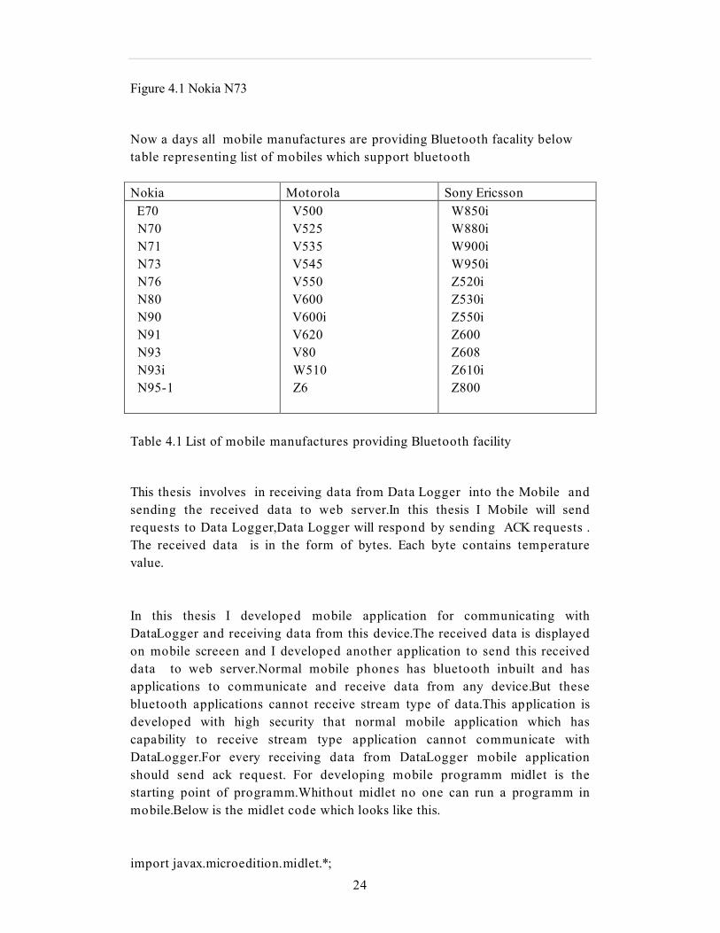
Figure 4.1 Nokia N73
Now a days all mobile manufactures are providing Bluetooth facality below
table representing list of mobiles which support bluetooth
Nokia Motorola Sony Ericsson
E70
N70
N71
N73
N76
N80
N90
N91
N93
N93i
N95-1
V500
V525
V535
V545
V550
V600
V600i
V620
V80
W510
Z6
W850i
W880i
W900i
W950i
Z520i
Z530i
Z550i
Z600
Z608
Z610i
Z800
Table 4.1 List of mobile manufactures providing Bluetooth facility
This thesis involves in receiving data from Data Logger into the Mobile and
sending the received data to web server.In this thesis I Mobile will send
requests to Data Logger,Data Logger will respond by sending ACK requests .
The received data is in the form of bytes. Each byte contains temperature
value.
In this thesis I developed mobile application for communicating with
DataLogger and receiving data from this device.The received data is displayed
on mobile screeen and I developed another application to send this received
data to web server.Normal mobile phones has bluetooth inbuilt and has
applications to communicate and receive data from any device.But these
bluetooth applications cannot receive stream type of data.This application is
developed with high security that normal mobile application which has
capability to receive stream type application cannot communicate with
DataLogger.For every receiving data from DataLogger mobile application
should send ack request. For developing mobile programm midlet is the
starting point of programm.Whithout midlet no one can run a programm in
mobile.Below is the midlet code which looks like this.
import javax.microedition.midlet.*;
25
import javax.microedition.lcdui.*;
public class Mobile extends MIDlet {
public void startApp() {
}
Public void pauseApp () {
}
Public void destroyApp (Boolean unconditional) {
}
}
The first three methods, startApp (), pauseApp () and destroyApp () are
needed for any MIDlet [3]. They come from extending the MIDlet class. The
next method, command Action () comes from the Command Listener
interface. This is needed to catch command events. The MIDlet is extended to
support Bluetooth communication with Data Logger.
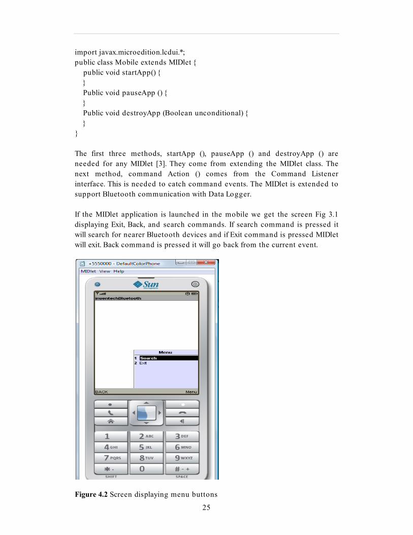
If the MIDlet application is launched in the mobile we get the screen Fig 3.1
displaying Exit, Back, and search commands. If search command is pressed it
will search for nearer Bluetooth devices and if Exit command is pressed MIDlet
will exit. Back command is pressed it will go back from the current event.
Figure 4.2 Screen displaying menu buttons
26
Device discovery:-
If search command is pressed class local device will get local device
information by calling getLocalDevice () and Local Device object is used to
obtain discovery agent by calling getDiscoveryAgent ()[6]. Discovery agent will
start inquiry for remote devices.
Local device= LocalDevice.getLocalDevice ();
Discovery agent = local.getDiscoveryAgent ();
The discovered devices are catched in device discovered method and the
discovered devices are stored in a vector. After devices are discovered the
screen will display the Bluetooth address of the discovered devices. Below is
the method where the discovered devices are catched and stored in vector.
The inquiry Completed () method is called when the inquiry ends.
If we want to stop the inquiry stop command is pressed. The inquiry
Completed () method is invoked if stop command is pressed. Below Fig 4.2
screen displaying stop command. After inquiry is stopped the screen will
display all the friendly Bluetooth addresses. We used this ’stop’ command
when the discovery process is taking time or when the required device is
found immediately.

27
Figure 4.3 Mobile screen displaying stop command.
Public void device Discovered (Remote Device remoteDevice, DeviceClass cod)
{
}
After inquiry is completed friendly names are displayed on the screen in Fig
3.2.

28
Figure 4.4 Screen displaying discovered devices
Now the screen is displaying all the discovered devices, after device discovery
is completed it is the time to find out which services are offered by the
discovered devices. This is accomplished by doing a service discovery on the
device of interest.
The services Discovered () and
serviceSearchCompleted () methods will handle the events occuring when
services are found or the service discovery completes. From
servicesDiscovered () method we get service record which is used to find
connectionURL.
Public void services Discovered (int transID, Service Record [] service Record) {
}
After service search is completed Mobile will establish a client Bluetooth
connection using serial port profile.

29
Figure4.5 Waiting for permission to Figure 4.6 Receiving
communication
Connect with Data logger requests from Data
Logger
Now you can see the Mobile screen Fig 4.4 asking for permission whether to
create connection with Data Logger or not. If ’yes’ button is pressed Mobile
starts sending first request Req_HandShake to Data Logger In response to this
request we should get Feedback_HandShake_Done request from Data Logger.
Below you can see the input Requests.
Data Logger board cooperates with top level system by sending / receiving
messages. Each message is wrapped into frame structure.
30
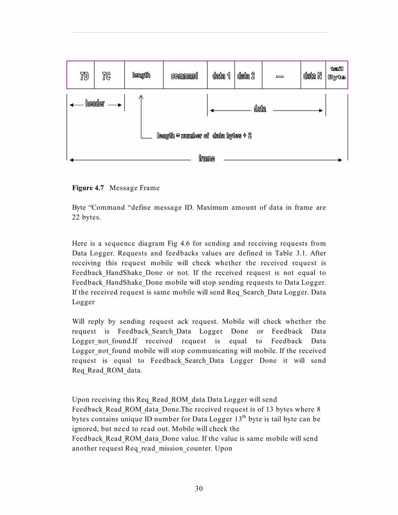
Figure 4.7 Message Frame
Byte “Command “define message ID. Maximum amount of data in frame are
22 bytes.
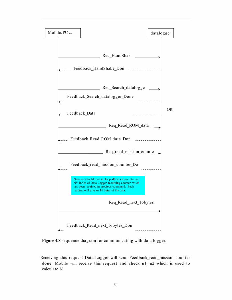
Here is a sequence diagram Fig 4.6 for sending and receiving requests from
Data Logger. Requests and feedbacks values are defined in Table 3.1. After
receiving this request mobile will check whether the received request is
Feedback_HandShake_Done or not. If the received request is not equal to
Feedback_HandShake_Done mobile will stop sending requests to Data Logger.
If the received request is same mobile will send Req_Search_Data Logger. Data
Logger
Will reply by sending request ack request. Mobile will check whether the
request is Feedback_Search_Data Logger Done or Feedback Data
Logger_not_found.If received request is equal to Feedback Data
Logger_not_found mobile will stop communicating will mobile. If the received
request is equal to Feedback_Search_Data Logger Done it will send
Req_Read_ROM_data.
Upon receiving this Req_Read_ROM_data Data Logger will send
Feedback_Read_ROM_data_Done.The received request is of 13 bytes where 8
bytes contains unique ID number for Data Logger 13th byte is tail byte can be
ignored, but need to read out. Mobile will check the
Feedback_Read_ROM_data_Done value. If the value is same mobile will send
another request Req_read_mission_counter. Upon
31
Figure 4.8 sequence diagram for communicating with data logger.
Receiving this request Data Logger will send Feedback_read_mission counter
done. Mobile will receive this request and check n1, n2 which is used to
calculate N.
Mobile/PC…. datalogge
r
Req_HandShak
e
Feedback_HandShake_Don
e
Req_Search_datalogge
r Feedback_Search_datalogger_Done
OR Feedback_Data
Loggers_not_found
Req_read_mission_counte
r
Feedback_read_mission_counter_Do
ne
Now we should read in loop all data from internal
NV RAM of Data Logger according counter, witch
has been received in previous command. Each
reading will give us 16 bytes of the data.
Req_Read_next_16bytes
Feedback_Read_next_16bytes_Don
e
Req_Read_ROM_data
Feedback_Read_ROM_data_Don
e

32
Where n1, n2 - values, used to calculate amount of the data in NV RAM of the
Data Logger.
N= n1+ 256*n2. if N >2048 only 2048 measurements need to be readout
and used!.
n3: not used, but need to be readout;
Tail byte: can be ignored, but need to be readout.
Depending on the N value mobile will decide how many requests should
send to Data Logger. The value of Req_Read_next_16bytes=0x7D, 0x7C, 4,
0x82, TA1, TA2, tail byte.
TA1, TA2 - define address of the data in NV RAM of the Data Logger, where
we should start next read cycle.
Address= TA1+256*TA2;
Data storage in Data Logger start from the address 0x1000
Tail byte: Calculated as logical OR for 3 bytes: 0x82, TA1, TA2.
For fist sending Req_Read_next_16bytes request
TA1=0X00.
TA2=0X10.
tail_byte=0x92.
like this maximum measurements need to be read out is up to 0x2048. After
Data Logger receiving this request it will send
Feedback_Read_next_16bytes_Done. This request is of size 21 bytes in which
16 bytes contains data. These 16 bytes are used to calculate temperature.
33
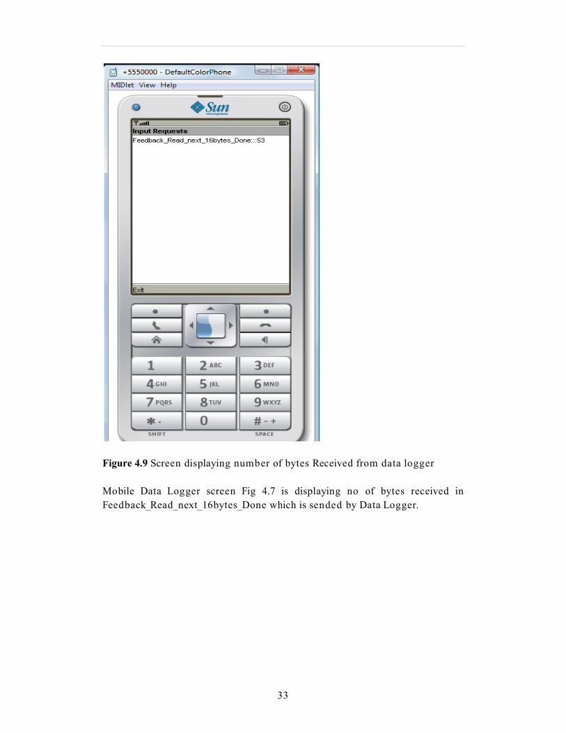
Figure 4.9 Screen displaying number of bytes Received from data logger
Mobile Data Logger screen Fig 4.7 is displaying no of bytes received in
Feedback_Read_next_16bytes_Done which is sended by Data Logger.

34
Requests &feedbacks
…………..name
Requests and feedbacks
Req_HandShake
0x7D,0x7C,2,0x20,0x20
Feedback_HandShake_Done
0x7D,0x7C,2,0x20,0x20
Req_Search_Data Logger
0x7D,0x7C,2,0x38,0x38
Feedback_Search_DataLogger_D
oe
0x7D,0x7C,3,0x38,1,0x39
Feedback_Data
Logger_not_found
0x7E,0x7B,2,0xB0,0xC0
Req_Read_ROM_data
0x7E,0x7A,2,0x39,0x37
Feedback_Read_ROM_data_Don
e
0x7C,0x7C,0x0E,0x39,rom_1,rom_2.rom_3,rom_4,rom_
5,rom_6,rom_7,rom_8, tail_byte;
Where: rom_1 – rom_8 - 8 bytes unique ID number
for Data Logger,
tail byte: can be ignored , but need to be
readout.
Req_read_mission_counter
0x7F,0x7D,2,0x5F,0x5F
Feedback_read_mission
counter_Done
0x7E,0x7C,5,0x5F,n1,n2.n3, tail byte;
Where: n1, n2 - values, used to calculate amount of
the data in NV RAM of the Data Logger.
N= n1+ 256*n2. if N >2048 only 2048
measurements need to be readout and used!.
n3:not used, but need to be readout;
Tail byte: can be ignored, but need to be
readout.
Req_Read_next_16bytes
0x7C,0x7A,4,0x92,TA1,TA2. tail_byte;
where: TA1, TA2 - define address of the data in NV
RAM of the Data Logger, where we should start next
read cycle,
Address= TA1+256*TA2;
Data storage in Data Logger start from the address
0x1000
35
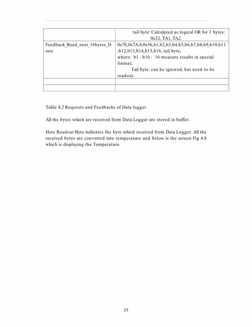
tail byte: Calculated as logical OR for 3 bytes:
0x32, TA1, TA2.
Feedback_Read_next_16bytes_D
one
0x7E,0x7A,4,0x56,b1,b2,b3,b4,b5,b6,b7,b8,b9,b10,b11
,b12,b13,b14,b15,b16, tail byte;
where: b1 –b16 : 16 measure results in special
format;
Tail byte: can be ignored, but need to be
readout.
Table 4.2 Requests and Feedbacks of Data logger
All the bytes which are received from Data Logger are stored in buffer.
Here Readout Byte indicates the byte which received from Data Logger. All the
received bytes are converted into temperature and below is the screen Fig 4.8
which is displaying the Temperature.

36
Figure 4.10 Mobile screen displaying Figure 4.11 Waiting for user permission to
Temperature connects to web server.
The received data can be sending to web server by pressing send button. Send button
can be seen in Fig 4.9. When send button is pressed the screen will display that
sending may result in charges if we press yes will be sent to web server.
37
4.4 Sending data to web server from MIDlets
We can send the received data from I button to users in three ways. By using GSM we can send data to internet where we can display data. We can use Bluetooth and RS232
to send data to PC from pc we can send the data to web server to view in online.
Users can view the received data by using Wireless LAN which can be used to send
data to another device like PC. In this thesis i used GSM to send data to web server.
Midlets to interact with Jsp web pages first Http Connection interface should be done
to establish HTTP connections.
The Connected Limited Device Configuration (CLDC) provides a set of classes for
network connectivity, collectively known as the generic connection framework. This
is a platform independent framework which provides a hierarchy of connectivity
interfaces, the implementation os is provided by profiles such as the Mobile
Information Device Profile (MIDP).
The MIDP extends the CLDC generic connection framework by providing the Http
Connection framework to support HTTP. All MIDP implementations are required to
include support for HTTP, and this is mainly because HTTP can either be
implemented using IP-based protocols (such as TCP/IP) or non-IP protocols.
Connections are produced using the open () method of the Connector class. If
successful, this method will return an object to implements one of the generic
connection interfaces. The following code is used to open HTTP connection
Http Connection connection= Connector. Open (url);
Once a connection is established, we should set some properties, and I/O
streams can be established to send and receive data. The following snippet of
code sets properties and establishes I/O streams.
HTTP properties
connection.setRequestMethod (HttpConnection.POST);
Creating I/O streams
InputStream is = connection.openInputStream();
In this way we send and receive data from JSP page.
38
5 Demonstration and some test results
This chapter explains demonstration of MIDlets and test results for different
networking distances. Section 5.2 explains test results of networking distance
(radio range between mobile and data logger) and section 5.3 explains co
channel interference.
5.1 Demonstration
When MIDlet is launched the screen displays with the name inventech
Bluetooth. When search button is pressed mobile will search for the remote
devices, after devices discovery is finished the screen is displayed with friendly
names of the founded remote devices. Now we will connect to the device of
interest, in this thesis we will connect to Data Logger device. It will search for
RFCOMM service on the Data Logger device, if it is having RFCOMM service it
will connect and opens the service to send and receive data. First mobile will
send first request to Data Logger like this both will communicate with sending
and receiving requests. Last request is send to Data Logger depends on how
much data we want to read out. For every received byte from Data Logger is
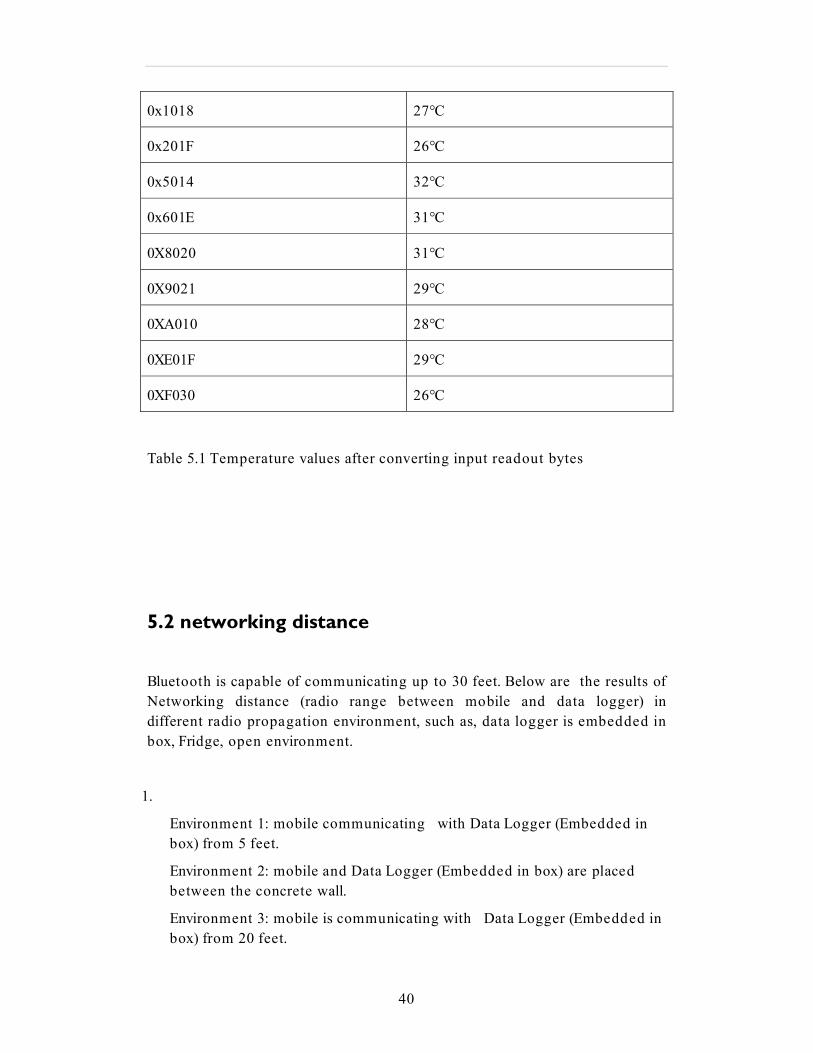
used to calculate Temperature Table [5.1] showing the temperature values for
every sending request. Fig 4.1 displaying the temperature value.
39
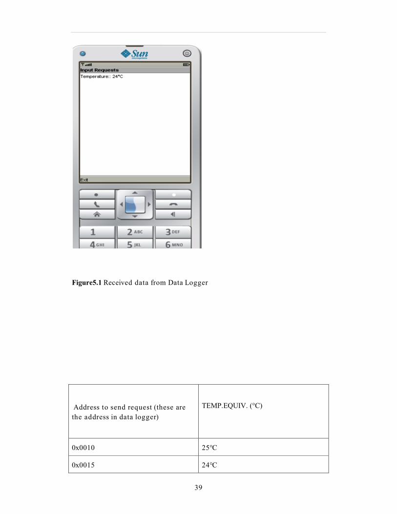
Figure5.1 Received data from Data Logger
Address to send request (these are
the address in data logger)
TEMP.EQUIV. (°C)
0x0010 25°C
0x0015 24°C
40
0x1018 27°C
0x201F 26°C
0x5014 32°C
0x601E 31°C
0X8020 31°C
0X9021 29°C
0XA010 28°C
0XE01F 29°C
0XF030 26°C
Table 5.1 Temperature values after converting input readout bytes
5.2 networking distance
Bluetooth is capable of communicating up to 30 feet. Below are the results of
Networking distance (radio range between mobile and data logger) in
different radio propagation environment, such as, data logger is embedded in
box, Fridge, open environment.
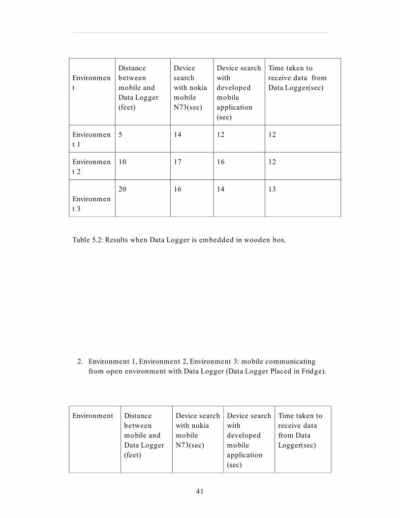
1.
Environment 1: mobile communicating with Data Logger (Embedded in
box) from 5 feet.
Environment 2: mobile and Data Logger (Embedded in box) are placed
between the concrete wall.
Environment 3: mobile is communicating with Data Logger (Embedded in
box) from 20 feet.
41
Environmen
t
Distance
between
mobile and
Data Logger
(feet)
Device
search
with nokia
mobile
N73(sec)
Device search
with
developed
mobile
application
(sec)
Time taken to
receive data from
Data Logger(sec)
Environmen
t 1
5 14 12 12
Environmen
t 2
10 17 16 12
Environmen
t 3
20 16 14 13
Table 5.2: Results when Data Logger is embedded in wooden box.
2. Environment 1, Environment 2, Environment 3: mobile communicating
from open environment with Data Logger (Data Logger Placed in Fridge).
Environment
Distance
between
mobile and
Data Logger
(feet)
Device search
with nokia
mobile
N73(sec)
Device search
with
developed
mobile
application
(sec)
Time taken to
receive data
from Data
Logger(sec)
42
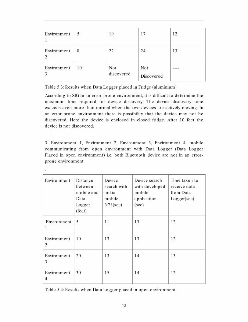
Environment
1
5 19 17 12
Environment
2
8 22 24 13
Environment
3
10 Not
discovered
Not
Discovered
----
Table 5.3: Results when Data Logger placed in Fridge (aluminium).
According to SIG In an error-prone environment, it is difficult to determine the
maximum time required for device discovery. The device discovery time
exceeds even more than normal when the two devices are actively moving. In
an error-prone environment there is possibility that the device may not be
discovered. Here the device is enclosed in closed fridge. After 10 feet the
device is not discovered.
3. Environment 1, Environment 2, Environment 3, Environment 4: mobile
communicating from open environment with Data Logger (Data Logger
Placed in open environment) i.e. both Bluetooth device are not in an error-
prone environment
.
Environment
Distance
between
mobile and
Data
Logger
(feet)
Device
search with
nokia
mobile
N73(sec)
Device search
with developed
mobile
application
(sec)
Time taken to
receive data
from Data
Logger(sec)
Environment
1
5 11 13 12
Environment
2
10 13 13 12
Environment
3
20 13 14 13
Environment
4
30 15 14 12
Table 5.4: Results when Data Logger placed in open environment.

43
As I described earlier according to the Bluetooth specifications, the device
takes at least 10.24 seconds for discovery. As per the test results it can be seen
that for device discovery it is taken at least 10.24 seconds. Device discovery
time depends on environment conditions. From Table 2 we can clearly seen
that when the Data Logger embedded in box, mobile is taking time to
discover device. When Data Logger is placed in open environment mobile can
discover and communicate with Data Logger from 30 feet also but when it is
embedded in box mobile is not able to discover devices more than 10 feet.
Here I discovered Bluetooth devices with developed Mobile application and
with nokia mobile which has Bluetooth enabled in it. The results are similar
when I discovered with nokia mobile and developed mobile application using
Bluetooth.
From the above results we can see that to receive data from Data Logger it is
taking approx 12 to 13 sec. The data which we are receiving are temperature
values. Amount of data which we received from Data Logger depends on how
much data stored in Data Logger. Every time the amount of time to received
data is not fixed. To receive 1024 bytes from Data Logger approx mobile is
taking 12 to 13 sec this is because for every sending request from Mobile we
get 16 bytes of data. Communication time depends on’ sending request
receiving request verification’. For every received request mobile will check
whether the received request is correct or not.
There is one way to reduce whole communication time. One thing is while
discovering devices if we found our device in mobile screen and immediately
if we stop the inquiry process we can reduce device discovery time. Approx we
can reduce 5 sec or more than that. In this thesis I provided command option
with key name ’stop’. If we press this button we can stop the inquiry process.
Anyhow every time we don’t need to receive 1024 bytes so if we are receiving
50 bytes, receiving data time will be approx 2 sec. So whole communicating
time to discovery device and receiving data in this case is 7 sec.
5.3 co-channel interference
To check co-channel interference I made communication environment such
that at a time mobile is communicating with Data Logger and PC is
communicating with another mobile and both are sending and receiving data.
I found that developed mobile application is working efficiently and I did not
found data loss. Mobile is able to receive data correctly from Data Logger.

44
Conclusion and discussions
45
6 Conclusion and discussions
The developed mobile application can send and receive data from Data
Logger and can display on the mobile screen. Now it can send the received
data to web server using GPRS. Better command options are created for user.
Now the user can start discovering devices and can stop discovery in middle
by using ‘stop’ command. If the user wants to send the data to web server he
can use ‘send’ command and he can see the received data on mobile screen.
Now the developed application can discover devices with similar discover time
compared to Nokia mobile within built-in Bluetooth enable in it.
Bluetooth solution is better when compared to wires in terms of cost, power.
When using wires cost of R232 converter, cost of twisted wires, cost of labor
for installing sensors, cost of power, cost of switches etc comes into
consideration. For measuring temperature values we need one pc. But we can
get the temperature values and graph in mobile itself. When using Bluetooth
we don’t need to lay wires, Just mobile is enough which has Bluetooth
enabled in it to receive data and sensors cost comes into consideration. We
can get the temperature readings when power is not able at measuring time.
Benefits are more when using wireless over wired.
For future work Mobile application should be developed to program Data
Logger using Bluetooth and another Mobile application should be developed
to display graph for received temperature values. Communication time to
send and receive data should be decreased. Better screen should be
developed. Pictures should be displayed for discovered devices to distinguish
between mobile and pc devices.PIM Phone calendar should be developed for
programming new mission so that user can select date and time to start data
logger for measuring temperature and he should have facility to save some
entries. Any case of possibilities of errors should be handled.
References
46
References
[1]: http://www.palowireless.com/INFOTOOTH/tutorial/k1_gap.asp
[2]: http://www.bluetooth.org
[3]: B. Hopkins and R. Antony, Bluetooth for Java, First Edition, Apress, 2003.
[4]: http://datasheets.maxim-ic.com/en/ds/DS1921G.pdf
[5]: http://java.sun.com/javame/reference/apis/jsr082/constant-
values.html#javax.bluetooth.DiscoveryListener.SERVICE_SEARCH_TERMINATED
[6]: http://developers.sun.com/mobility/apis/articles/bluetoothcore/index.html
[7]: http://wireless.klings.org
[8]: http://java.sun.com/products/j2mewtoolkit/
[9]: http://www.netbeans.org
[10]: http://www.bluetooth.com
[11]: http://java.sun.com/j2me/
[12]: http://java.sun.com/products/cldc/
[13]: http://faculty.cs.byu.edu/~knutson/publications/IrDA_Assisted_BT_Discovery.pdf

Appendix
47
Appendix 1
Device Types and Control signals of RFCOMM
Basically two device types exist that RFCOMM must accommodate.
• Type 1 Devices are communication end points such as computers and printers.
• Type 2 Devices are those that are part of the communication segment; e.g.
modems.
Though RFCOMM does not make a distinction between these two device types in the
protocol, accommodating both types of devices impacts the RFCOMM protocol.
The information transferred between two RFCOMM entities has been defined to
support both type 1 and type 2 devices. Some information is only needed by type 2
devices while other information is intended to be used by both. In the protocol, no
distinction is made between type 1 and type 2. Since the device is not aware of the
type of the other device in the communication path, each must pass on all available
information specified by the protocol.
Control Signals of RFCOMM
RFCOMM emulates the 9 circuits of an RS-232 interface. The circuits are listed
below.
Pin Circuit Name
102 Signal Common
103 Transmit Data (TD)
104 Received Data (RD)
105 Request to Send (RTS)
106 Clear to Send (CTS)
107 Data Set Ready (DSR)
108 Data Terminal Ready (DTR)
109 Data Carrier Detect (CD)
125 Ring Indicator (RI)
Appendix
48
Appendix 2
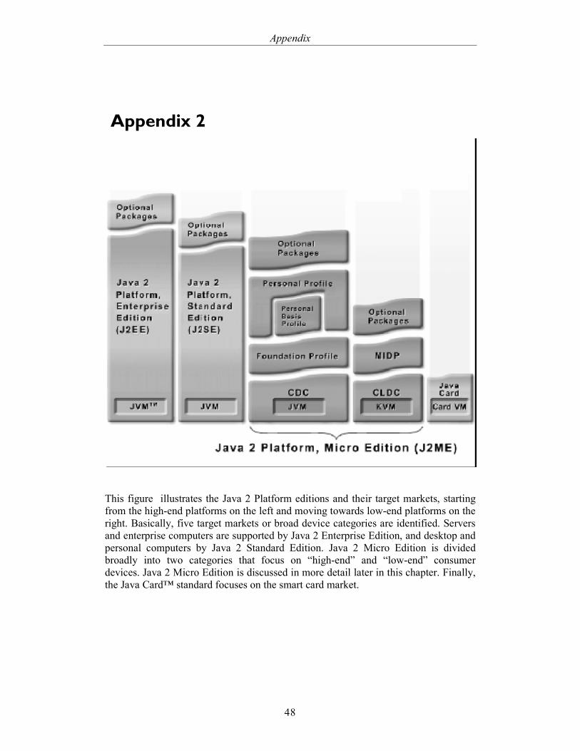
This figure illustrates the Java 2 Platform editions and their target markets, starting
from the high-end platforms on the left and moving towards low-end platforms on the
right. Basically, five target markets or broad device categories are identified. Servers
and enterprise computers are supported by Java 2 Enterprise Edition, and desktop and
personal computers by Java 2 Standard Edition. Java 2 Micro Edition is divided
broadly into two categories that focus on “high-end” and “low-end” consumer
devices. Java 2 Micro Edition is discussed in more detail later in this chapter. Finally,
the Java Card™ standard focuses on the smart card market.

Appendix
49