solids handouts 10
TRANSCRIPT

8/2/2019 Solids Handouts 10
http://slidepdf.com/reader/full/solids-handouts-10 1/8
HANDOUT 10-1
xxσ
θ
xyσ
yxσ
yyσ
yyσ
xyσ
yxσ
xxσ
(a)
Normal
Shear
Min
Max(b)
MAX NORMAL
NORMAL
AXIS
S H E A R
S T R E S
S A X I S
MIN NORMAL
MOHR
CIRCLE
(c)

8/2/2019 Solids Handouts 10
http://slidepdf.com/reader/full/solids-handouts-10 2/8
HANDOUT 10-2
Normal Stress
S h e a r S t r e s s
Critical Point
(End Point)
Normal Stress
S h e a r S t r e s s
c f
Normal Stress
Critical Point
(End Point)
1σ
JYL
S h e a r S t r e s s
JYL
JYL

8/2/2019 Solids Handouts 10
http://slidepdf.com/reader/full/solids-handouts-10 3/8
HANDOUT 10-3
Normal Stress
S h e a r S t r e s s
Critical Points
δ
MFF
Non-cohesive
Less cohesive
More cohesive
Multiple JYL
curves
c f
1σ

8/2/2019 Solids Handouts 10
http://slidepdf.com/reader/full/solids-handouts-10 4/8
HANDOUT 10-4
0
10
20
30
40
50
0 10 20 30 40 50 60 70
Semi-included angle, degrees
W a l l F r i c t i o n , d
e g r e e s
1
1.1
1.2
1.3
1.4
1.5
1.6
1.7
1.8
1.9
2
δ=30
δ=40
δ=60
δ=50
δ=60
δ=40
δ=30
δ=50
δ=60
δ=50
δ=45
δ=40
δ=35
δ=30
F l o w F a
c t o r , f f
Flow Factor Curves
Wall Friction Curves
Figure 10-17. Design chart for symmetrical slot outlet hoppers. For example (dashed arrows),
and gives and
o22=wδ o50=δ o5.30=θ 19.1= ff .

8/2/2019 Solids Handouts 10
http://slidepdf.com/reader/full/solids-handouts-10 5/8
HANDOUT 10-5
0
10
20
30
40
0 5 10 15 20 25 30 35 40 45
Semi-included angle, degrees
W a l l F r i c t i o n ,
d e g
r e e s
1
1.1
1.2
1.3
1.4
1.5
1.6
1.7
1.8
1.9
2
δ=30
δ=40
δ=60
δ=50
δ=60
δ=40
δ=30
δ=50
δ=60
δ=50
δ=40
δ=35
δ=30
F l o w F a c t o
r , f f
Flow Factor Curves
Wall Friction Curves
Figure 10-18. Design chart for conical outlet hoppers. For example, and gives
and .
o22=wδ o50=δ
o5.20=θ 29.1= ff

8/2/2019 Solids Handouts 10
http://slidepdf.com/reader/full/solids-handouts-10 6/8
HANDOUT 10-6
Steps on using the shear stress data to design a hopper.
1. Rotating Shear Test
Plot SHEAR STRESS
vsNORMAL STRESS
Internal Friction
Get f c vs σ 1Get δ
δ
SHEARSTRESS
f c σ 1
NORMAL STRESS
JYL
SHEAR
STRESS
wδ
2. Rotating Shear Test
Wall material
Get wδ
NORMAL STRESS
3. Fit φ w and δ to hopper correlation
Get θ and ff .
(θ is the theoretical
angle of the hopper;in final design subtract
3 degrees for margin of
safety)
4. Plot 1/ ff on mff curve ( f c vs σ 1) to get CAS
Get CAS
δ
δ
wφ
ff
θ
MFFCAS
f c
Slope 1/ ff
σ 15. Use CAS and θ in correlations to select opening size.

8/2/2019 Solids Handouts 10
http://slidepdf.com/reader/full/solids-handouts-10 7/8
HANDOUT 10-7
D
θ Semi included angle
For conical hoppers, Figure 10-20, the opening
diameter, , is given by D
c
ogg
CAS H D
/ )( ρ
θ = (10-12)
602)(
θ θ += H (10-13)
Where θ is in degrees, from the charts in
Figures 10-17 or 10-18. Typical values for H are
about 2.4.
Figure 10-20. Conical Hopper with outlet size D
and semi included angle θ .
L
W
For symmetrical slot outlet hoppers the opening
size is determined from
c
ogg
CAS H W
/ )( ρ
θ = (10-14)
180
1)(θ
θ += H (10-15)
W L 3> (10-16)
Figure 10-21. Symmetrical slot outlet h
of opening size W x L.
opper
8/2/2019 Solids Handouts 10
http://slidepdf.com/reader/full/solids-handouts-10 8/8
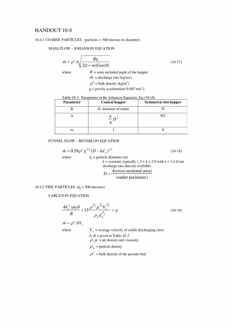
HANDOUT 10-8
10.4.1 COARSE PARTICLES (particles > 500 microns in diameter)
MASS FLOW – JOHANSON EQUATION
)()1(2 θ ρ
Tanm
Bg Am
o
+=& (10-17)
where θ = semi included angle of the hopper
m& = discharge rate (kg/sec)o ρ = bulk density (kg/m3)
g = gravity acceleration (9.807 m/s2)
Table 10-3. Parameters in the Johanson Equation, Eq.(10-18)
Parameter Conical hopper Symmetric slot hopper
B D, diameter of outlet W
A 2
4 D
π
WL
m 1 0
FUNNEL FLOW – BEVERLOO EQUATION
5.25.0 )(58.0 p
okd Dgm −= ρ & (10-18)
where d p = particle diameter (m)
k = constant, typically 1.3 < k < 2.9 with k = 1.4 if not
discharge rate data are available.
)perimeteroutlet()areasectionalcross(4= D
10.4.2 FINE PARTICLES (d p < 500 microns)
CARLETON EQUATION
g
d
V
B
V
p p
oo=+
35
34
32
31
2
15sin4
ρ
µ ρ θ (10-19)
o
o AV m ρ =&
where = average velocity of solids discharging (m/s)oV A, B = given in Table 10-3
µ ρ , = air density and viscosity
p ρ = particle density
o ρ = bulk density of the powder bed