specifications for approval - ЗАО ...bec.by/upload/pdf/lemwm14280mz10.pdfspecifications for...
TRANSCRIPT
CUSTOMER : .
DATE : 2012. 02. 24.
SPECIFICATIONS FOR APPROVAL
APPROVAL REMARK APPENDIX Designed Checked Approved
고효율 COB PKG(Warm White/ 2,700K)MODEL NAME : LEMWM14280MZ10

(30)-4022
SPECIFICATION
MODEL LEMWM14280MZ10 DOCUMENT No
REG.DATE 2012. 03. 16 REV. No 0.1
REV.DATE - PAGE /20
LGIT Confidential and Proprietary
Change History of Revision
Revision Date Contents of Revision Change Remark
Rev. 1.0 ’11.03.16 New establishment
2

(30)-4022
SPECIFICATION
MODEL LEMWM14280MZ10 DOCUMENT No
REG.DATE 2012. 03. 16 REV. No 0.1
REV.DATE - PAGE /20
LGIT Confidential and Proprietary
CONTENTS
1. Features
2. Outline dimensions
3. Applications
4. Characteristics (Ta = 25℃)
5. Absolute Maximum Ratings
6. Chromaticity on the 1931 CIE Curve
7. Performance Groups - Chromaticity
8. Typical Characteristic Curves
9. Reliability Test Items and Conditions
10. Packing and Marking of Product
11. Cautions on use
12. Reflow Soldering Characteristics
3 / 20
4 / 20
5 / 20
5 / 20
6 / 20
9 / 20
7 / 20
11 / 20
12 / 20
19 / 20
15 / 20
5 / 20
3

(30)-4022
SPECIFICATION
MODEL LEMWM14280MZ10 DOCUMENT No
REG.DATE 2012. 03. 16 REV. No 0.1
REV.DATE - PAGE /20
LGIT Confidential and Proprietary
1. Features
( unit : mm )
2. Outline Dimensions
- High flux power LED module with 4 LED
-Compact design (14mmX14mm)
-110˚ light distribution pattern, uniform illumination
-Low thermal resistance Rth,j-board < 5 K/W
-High-power LED in COB technology
◆Tolerances Unless Dimension ±0.2mm
4
< Internal Circuit >
Dome#1 Dome#2
Dome#3 Dome#4
Hybrid-Type Die attach
(Sanyu-Rec社)

(30)-4022
SPECIFICATION
MODEL LEMWM14280MZ10 DOCUMENT No
REG.DATE 2012. 03. 16 REV. No 0.1
REV.DATE - PAGE /20
LGIT Confidential and Proprietary
3. Applications
4. Characteristics ( Ta=25℃ )
- General Lighting
- Effect and design lighting
- Emergency lighting
- Spotlights
Items Symbol Min Typ Max Unit
All data for Ta=25℃, IF=400mA
Power *1) Po 3.17 3.56 3.63 W
Forward Voltage *1) VF 5.88 6.50 6.70 V
Luminance Flux *1) ΦV 330 350 - lm
Luminous Efficacy Lm/W 90 100 - Lm/W
Color Temperature *1) CCT 2527 2775 2952 K
CRI *1) - 80 - Ra
Viewing Angle *1) 2Θ1/2 - 110 - deg
Junction Temperature *2) Tj 120 ℃
Thermal Resistance *2) Rth j-b 5 ℃/W
※ These values measured by Optical Spectrum Analyzer of LG Innotek Co., LTD
Tolerances are followings as below
- Luminous Flux (lm) : ±20%, CIE Value : ±0.01, CRI : ±2
※ Rthj-b = Thermal Resistance (Junction – Board)
If the maximum temperature limits are exceeded, the life of the module will be greatly reduced or the module
may be damaged
1) These values measured without heat sink
These values are based on 16-dies performance
2) These values is allowed to measure with a heat sink of aluminum.
5. Absolute Maximum Ratings ( Ta=25℃ )
Items Symbol Rating Unit
Forward Current IF 600 mA
Pulse Forward Current *1) IFp 750 mA
Operating Temperature Topr -30 ~ +55 ℃
Storage Temperature Tstg -40 ~ +100 ℃
*1) Pulse Width ≤ 10msec, Duty ≤ 10%
5
(30)-4022
SPECIFICATION
MODEL LEMWM14280MZ10 DOCUMENT No
REG.DATE 2012. 03. 16 REV. No 0.1
REV.DATE - PAGE /20
LGIT Confidential and Proprietary
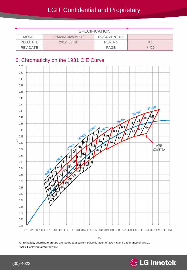
6. Chromaticity on the 1931 CIE Curve
•Chromaticity coordinate groups are tested at a current pulse duration of 300 ms and a tolerance of ±0.01.
•ANSI Cool/Neutral/Warm white
0.25
0.26
0.27
0.28
0.29
0.30
0.31
0.32
0.33
0.34
0.35
0.36
0.37
0.38
0.39
0.40
0.41
0.42
0.43
0.44
0.45
0.46
0.47
0.48
0.49
0.50
0.25 0.26 0.27 0.28 0.29 0.30 0.31 0.32 0.33 0.34 0.35 0.36 0.37 0.38 0.39 0.40 0.41 0.42 0.43 0.44 0.45 0.46 0.47 0.48 0.49 0.50
Cy
Cx
ANSI
C78.377A
H1
H2
H3
H4
H5
H6
H7
H8
I1
I2
I3
I4
I5
I6
I7
I8
J1
J2
J3
J4
K1
K2
K3
K4
L1
L2
L3
L4
M1
M2
M3
M4
6

(30)-4022
SPECIFICATION
MODEL LEMWM14280MZ10 DOCUMENT No
REG.DATE 2012. 03. 16 REV. No 0.1
REV.DATE - PAGE /20
LGIT Confidential and Proprietary
7. Performance Group - Chromaticity
CCT Rank CIE X CIE Y CCT Rank CIE X CIE Y CCT Rank CIE X CIE Y
2700K
( 2725K
±145K )
M1
0.4562 0.4260
4500K
( 4503K
±243K )
I1
0.3548 0.3736
5700K
( 5665K
±355K )
G1
0.3207 0.3462
0.4687 0.4289 0.3641 0.3804 0.3291 0.3538
0.4586 0.4103 0.3611 0.3638 0.3292 0.3382
0.4465 0.4071 0.3526 0.3575 0.3217 0.3314
M2
0.4465 0.4071
I2
0.3526 0.3575
G2
0.3217 0.3314
0.4586 0.4103 0.3611 0.3638 0.3292 0.3382
0.4483 0.3918 0.3590 0.3521 0.3293 0.3305
0.4373 0.3893 0.3512 0.3465 0.3222 0.3243
M3
0.4687 0.4289
I3
0.3641 0.3804
G3
0.3291 0.3538
0.4813 0.4319 0.3736 0.3874 0.3376 0.3616
0.4700 0.4126 0.3697 0.3697 0.3369 0.3449
0.4586 0.4103 0.3611 0.3638 0.3292 0.3382
M4
0.4586 0.4103
I4
0.3611 0.3638
G4
0.3292 0.3382
0.4700 0.4126 0.3697 0.3697 0.3369 0.3449
0.4593 0.3944 0.3670 0.3578 0.3366 0.3369
0.4483 0.3918 0.3590 0.3521 0.3293 0.3305
3000K
( 3045K
±175K )
L1
0.4299 0.4165
I5
0.3571 0.3907
G5
0.3196 0.3602
0.4430 0.4212 0.3668 0.3957 0.3290 0.3690
0.4344 0.4032 0.3641 0.3804 0.3291 0.3538
0.4221 0.3984 0.3548 0.3736 0.3207 0.3462
L2
0.4221 0.3984
I6
0.3512 0.3465
G6
0.3222 0.3243
0.4344 0.4032 0.3590 0.3521 0.3293 0.3305
0.4260 0.3853 0.3567 0.3389 0.3290 0.3180
0.4147 0.3814 0.3495 0.3339 0.3231 0.3120
L3
0.4430 0.4212
I7
0.3668 0.3957
G7
0.3290 0.3690
0.4562 0.4260 0.3771 0.4034 0.3381 0.3762
0.4465 0.4071 0.3736 0.3874 0.3376 0.3616
0.4344 0.4032 0.3641 0.3804 0.3291 0.3538
L4
0.4344 0.4032
I8
0.3590 0.3521
G8
0.3293 0.3305
0.4465 0.4071 0.3670 0.3578 0.3366 0.3369
0.4373 0.3893 0.3640 0.3440 0.3361 0.3245
0.4260 0.3853 0.3567 0.3389 0.3290 0.3180
3500K
( 3465K
±245K )
K1
0.3996 0.4015
5000K
( 5028K
±283K )
H1
0.3376 0.3616
6500K
( 6530K
±510K )
F1
0.3028 0.3304
0.4146 0.4089 0.3463 0.3687 0.3115 0.3391
0.4082 0.3922 0.3447 0.3513 0.3136 0.3237
0.3941 0.3848 0.3369 0.3449 0.3059 0.3160
K2
0.3941 0.3848
H2
0.3369 0.3449
F2
0.3059 0.3160
0.4082 0.3922 0.3447 0.3513 0.3136 0.3237
0.4017 0.3752 0.3440 0.3427 0.3144 0.3186
0.3889 0.3690 0.3366 0.3369 0.3068 0.3113
K3
0.4146 0.4089
H3
0.3463 0.3687
F3
0.3115 0.3391
0.4299 0.4165 0.3551 0.3760 0.3205 0.3481
0.4221 0.3984 0.3526 0.3575 0.3217 0.3314
0.4082 0.3922 0.3447 0.3513 0.3136 0.3237
K4
0.4082 0.3922
H4
0.3447 0.3513
F4
0.3136 0.3237
0.4221 0.3984 0.3526 0.3575 0.3217 0.3314
0.4147 0.3814 0.3515 0.3487 0.3221 0.3261
0.4017 0.3752 0.3440 0.3427 0.3144 0.3186
4000K
( 3985K
±275K )
J1
0.3736 0.3874
H5
0.3381 0.3762
F5
0.3005 0.3415
0.3870 0.3958 0.3480 0.3840 0.3099 0.3509
0.3819 0.3776 0.3463 0.3687 0.3115 0.3391
0.3697 0.3697 0.3376 0.3616 0.3028 0.3304
J2
0.3697 0.3697
H6
0.3366 0.3369
F6
0.3068 0.3113
0.3819 0.3776 0.3440 0.3427 0.3144 0.3186
0.3783 0.3646 0.3429 0.3307 0.3161 0.3059
0.3670 0.3578 0.3361 0.3245 0.3093 0.2993
J3
0.3870 0.3958
H7
0.3480 0.3840
F7
0.3099 0.3509
0.4006 0.4044 0.3571 0.3907 0.3196 0.3602
0.3941 0.3848 0.3551 0.3760 0.3205 0.3481
0.3819 0.3776 0.3463 0.3687 0.3115 0.3391
J4
0.3819 0.3776
H8
0.3440 0.3427
F8
0.3144 0.3186
0.3941 0.3848 0.3515 0.3487 0.3221 0.3261
0.3898 0.3716 0.3495 0.3339 0.3231 0.3120
0.3783 0.3646 0.3429 0.3307 0.3161 0.3059
Rank of CIE Value (@400mA)
7
(30)-4022
SPECIFICATION
MODEL LEMWM14280MZ10 DOCUMENT No
REG.DATE 2012. 03. 16 REV. No 0.1
REV.DATE - PAGE /20
LGIT Confidential and Proprietary
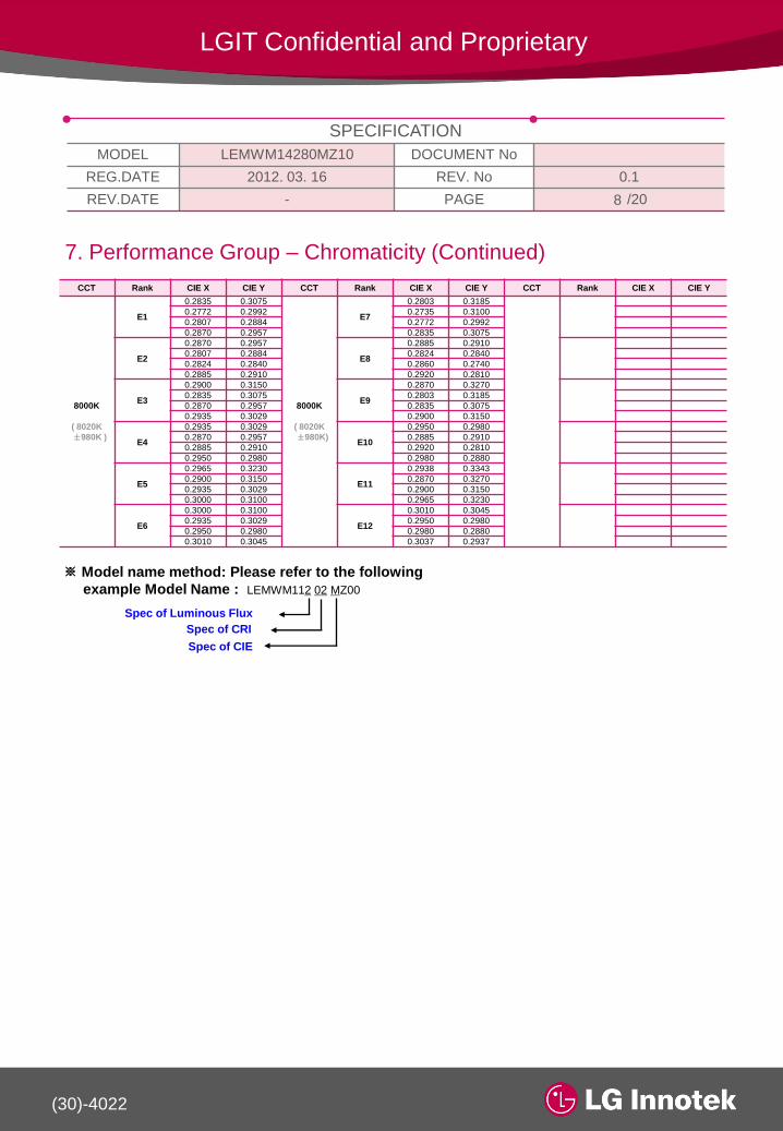
7. Performance Group – Chromaticity (Continued)
CCT Rank CIE X CIE Y CCT Rank CIE X CIE Y CCT Rank CIE X CIE Y
8000K
( 8020K
±980K )
E1
0.2835 0.3075
8000K
( 8020K
±980K)
E7
0.2803 0.3185
0.2772 0.2992 0.2735 0.3100
0.2807 0.2884 0.2772 0.2992
0.2870 0.2957 0.2835 0.3075
E2
0.2870 0.2957
E8
0.2885 0.2910
0.2807 0.2884 0.2824 0.2840
0.2824 0.2840 0.2860 0.2740
0.2885 0.2910 0.2920 0.2810
E3
0.2900 0.3150
E9
0.2870 0.3270
0.2835 0.3075 0.2803 0.3185
0.2870 0.2957 0.2835 0.3075
0.2935 0.3029 0.2900 0.3150
E4
0.2935 0.3029
E10
0.2950 0.2980
0.2870 0.2957 0.2885 0.2910
0.2885 0.2910 0.2920 0.2810
0.2950 0.2980 0.2980 0.2880
E5
0.2965 0.3230
E11
0.2938 0.3343
0.2900 0.3150 0.2870 0.3270
0.2935 0.3029 0.2900 0.3150
0.3000 0.3100 0.2965 0.3230
E6
0.3000 0.3100
E12
0.3010 0.3045
0.2935 0.3029 0.2950 0.2980
0.2950 0.2980 0.2980 0.2880
0.3010 0.3045 0.3037 0.2937
※ Model name method: Please refer to the following
example Model Name : LEMWM112 02 MZ00
Spec of Luminous Flux
Spec of CRI
Spec of CIE
8

(30)-4022
SPECIFICATION
MODEL LEMWM14280MZ10 DOCUMENT No
REG.DATE 2012. 03. 16 REV. No 0.1
REV.DATE - PAGE /20
LGIT Confidential and Proprietary
8. Typical Characteristic Curves■ Forward Voltage vs. Forward Current ■ Spectrum
■ Forward Current vs. Luminous Flux ■ Input Watt vs. Luminance Flux
9
CCT2700K, Ta 25℃, @540mA
Forward Current(mA)
Rela
tive L
um
ino
us
Flu
x
Eff
ica
cy[l
m/W
]
Forward Current(mA)
0.70
0.75
0.80
0.85
0.90
0.95
1.00
1.05
30 40 50 60 70 80 90
Rela
tive L
um
ino
us F
lux[%
]
Solder Point Temperature [Ts, ℃] Solder Point Temperature [Ts, ℃]
Ch
rom
ati
cit
y C
oo
rdin
ate
■ Luninous Flux Vs TEMP. ■ CIE Vs TEMP
(30)-4022
SPECIFICATION
MODEL LEMWM14280MZ10 DOCUMENT No
REG.DATE 2012. 03. 16 REV. No 0.1
REV.DATE - PAGE /20
LGIT Confidential and Proprietary
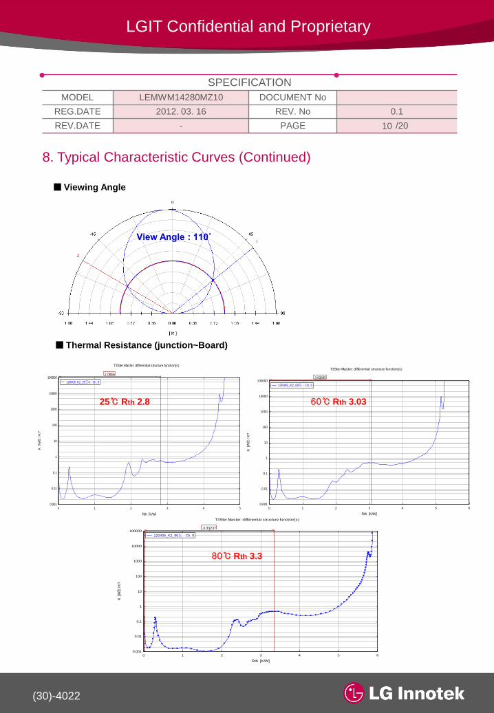
8. Typical Characteristic Curves (Continued)
■ Viewing Angle
■ Thermal Resistance (junction~Board)
10
View Angle : 110˚
0 1 2 3 4 50.001
0.01
0.1
1
10
100
1000
10000
100000
Rth [K/W]
K [W쾠
/ K
?
T3Ster Master: differential structure function(s)
2.79856
120405_K2_25도0 - Ch. 0
25℃ Rth 2.8
0 1 2 3 4 5 60.001
0.01
0.1
1
10
100
1000
10000
100000
Rth [K/W]
K [W쾠
/ K
?
T3Ster Master: differential structure function(s)
3.03885
120405_K2_60도 - Ch. 0
60℃ Rth 3.03
0 1 2 3 4 5 60.001
0.01
0.1
1
10
100
1000
10000
100000
Rth [K/W]
K [
W쾠
/ K
?
T3Ster Master: differential structure function(s)
3.33237
120405_K2_80도 - Ch. 0
80℃ Rth 3.3

(30)-4022
SPECIFICATION
MODEL LEMWM14280MZ10 DOCUMENT No
REG.DATE 2012. 03. 16 REV. No 0.1
REV.DATE - PAGE /20
LGIT Confidential and Proprietary
9. Reliability Test Items and Conditions
9-1.Criteria for Judging the Damage
9-2. Item and Results of Reliability Test
Item Symbol Test ConditionLimit
Min Max
Forward Voltage VF IF = 540mA S 0.80 S 1.20
Luminous Flux Ⅰ*1 ΦV IF = 540mA S 0.85 -
Luminous Flux Ⅱ*2 ΦV IF = 540mA S 0.70 -
No Item Test ConditionTest Hours/
Cycles
Sample
NoAc/Re
1 Steady State Operating Life*1 Ta=25℃, IF=540 [mA] 1000hr 22 pcs 0 / 1
2 High Temp. Humidity Life Ta=60℃,90% RH,IF=540 [mA] 1000hr 22 pcs 0 / 1
3Steady State Operating Life
of High TemperatureⅠTa=60℃, IF=540 [mA] 1000hr 22 pcs 0 / 1
4Steady State Operating Life
of High TemperatureⅡTa=85℃, IF=540 [mA] 1000hr 22 pcs 0 / 1
5Steady State Operating Life
of Low Temperature*1 Ta= -30℃, IF=540 [mA] 1000hr 22 pcs 0 / 1
6 High Temp. Storage 100℃ 1000hr 22 pcs 0 / 1
7 Low Temp. Storage -40℃ 1000hr 22 pcs 0 / 1
8 Temperature Cycle-40℃(30min) ~ 25℃(5min)
~ 100℃(30min) ~ 25℃(5min)100cycle 22 pcs 0 / 1
9 Thermal Shock 100℃(30min) ~ -40℃(30min) 100cycle 22 pcs 0 / 1
10
Resistance to
Soldering Heat
(Reflow Soldering)
Tsld = 260℃, 10s
(pre treat. 30℃, 70%, 168hr)1 times 22 pcs 0 / 1
11 Vibration200m/s2,100~2000Hz(sweep
4min) 48min, 3 directions4 times 22 pcs 0 / 1
12 Electrostatic DischargeR=1.5kΩ, C=100pF,
Test Voltage 2kV
3times
Negative/
Positive
22 pcs 0 / 1
*The operating test is allowed with a heat sink of aluminum, Heat sink surface is designed
for Bulb product
※ These test conditions are requested by the customer
* U.S.L : Upper Spec. Limit, S : Initial Value
11

(30)-4022
SPECIFICATION
MODEL LEMWM14280MZ10 DOCUMENT No
REG.DATE 2012. 03. 16 REV. No 0.1
REV.DATE - PAGE /20
LGIT Confidential and Proprietary
10. Package and Marking of Products
10-1. Tube Outline Dimension ◆ Packing Materials :
- Tube : PET
Dimension of Tube : 540 x 16 x 5.5
Insert Direction : 36units Per Tube
10-2. Packing Specifications
A rubber band ties the 10 Tubes (the number of PKGs are 360 pcs) and then that packed in a
vacuum seal off Packing Bag along with desiccants (Silicagel). 10 Packing Bag (total maximum
number of products are 3,600 pcs) packed in an inner box and 4 inner boxes are put into an outer
box. (total maximum number of products are 14,400 pcs)
105
260
622240
540
640
Label C
Label D
Label ALabel B
( unit : mm )
12

(30)-4022
SPECIFICATION
MODEL LEMWM14280MZ10 DOCUMENT No
REG.DATE 2012. 03. 16 REV. No 0.1
REV.DATE - PAGE /20
LGIT Confidential and Proprietary
※. Label A (Tube Label)
Model(Company's Name - Location of manufacture) , Date, Rank, LOT No,
Quantity, UL Trademark and UL File number
※ Label B (Packing Bag)
LOT NO, MODEL, RANK, Quantity, RUN NO
80mm
40mmMODEL : M14280M
RANK : 2-M55
Q’ty:360[pcs]
RUN No : P11A07 – 00039
PACK ID : MP11A07160001
M14280M = 2-M55 = 360 = P11A07 – 00039 = K-001
Rack No: H - 001
90mm
13mm
Model (LGIT – P ) : M14280M
Date : 2011 – 01 – 01
Rank : 2-M55
LOT ID : PPLE28M063T000101
BINQ’ty (pcs) : 36
017ES43718
13

(30)-4022
SPECIFICATION
MODEL LEMWM14280MZ10 DOCUMENT No
REG.DATE 2012. 03. 16 REV. No 0.1
REV.DATE - PAGE /20
LGIT Confidential and Proprietary
14
※ Label C (Inner Box Label)
LOT NO, MODEL, Quantity, Date, Rank (Multi-Rank)
80mm
40mmPKG MODEL : LEMWM14X80MZ00
Rank : U-M1 Q’ty:1,800[pcs]
Run No:Z00507-0714 Rack No:C-017
MRM Code:140HCL-0510-R3d-01B-n-04
LOT No:PPWW31Z063M000101
80mm
40mm
R3-D34L-A
D04q
PKG MODEL : LEMWM14X80MZ00
Rank : U-M1 Q’ty:1,800[pcs]
Run No:Z00507-0714 Rack No:C-017
MRM Code:140HCL-0510-R3d-01B-n-04
LOT No:PPWW31Z063M000101 R3-D34L-B
D04q
※ Label D
Specifying Customer, Date, Model Name, Quantity, Customer Part no, Outbox ID
Outbox ID. indication
1 2 3 4 5
Sit
e
9
Serial NoOutbox Date
( 01 ~ 31) ( 001 ~ 999 )
106 7 8
1~9 : 1~9
10 : A
11 : B
12 : C
PKG
Site
MonthYear
12 : 2
13 : 3
14 : 4
15 : 5
40mm
OutBox Customer
94LEMWS68T80LZ00
2012.03.10
PSO2221003
LEMWS68T80LZ00 30,000 N14
80mm
PSP12221-005
Lot No. indication
1 2 3 4 5
Code
6 7
Serial NoQA Inspection
Year
(Last number)
QA Inspection
Month
QA Inspection
Date
( 1, 2, 3, 4,
5, 6, 7, 8,
9, X, Y, Z )
( 01 ~ 31 )( 01 ~ 99 )
( 1, 2, 3, 4, 5,
6, 7, 8, 9, 0 )

(30)-4022
SPECIFICATION
MODEL LEMWM14280MZ10 DOCUMENT No
REG.DATE 2012. 03. 16 REV. No 0.1
REV.DATE - PAGE /20
LGIT Confidential and Proprietary
11. Cautions on use
11-1. Over-current-proof
Customer must apply resistors for protection, others slight voltage shift will cause big
current change. ( Burn out will happen )
LG Innotek will not be held responsible for any damage to the user that may result from
accidents or any other reasons during operation of the user’s unit if use to exceed the
absolute maximum ratings, or not keep the matters that demand special attention.
11-2. For the Storage
- Proper temperature and RH conditions for storage are : 5 ℃ ~35 ℃ , RH 60%.
- Do not open moisture-proof bag before the products are ready to use.
- Store products in a moisture-proof bag with a desiccant (Silica gel) after open.
- These products should be used within 168 hours after opening the bag based upon
storage condition.
- These products must be baked to remove moisture before using them if the Silica
gel loses its color. Conditions for baking are 60±5℃, 20% (RH) and 24 hours
maximum. (For reeled status without bag)
11-3. For the Usage
- LED PKG should not be used in directly exposed environment containing hazardous
substances.
- The LEDs has silver plated metal parts. The silver plating become tarnished when
being exposed to an environment which contains corrosive gases.
- After assembly and during use, silver plating can be affected by the corrosive gases
emitted by components and materials in close proximity of the LEDs within an end
product, and the gases entering into the product from the external atmosphere.
- Do not expose the LEDs to corrosive atmosphere during storage and using.
- Avoid rapid transitions in ambient temperature, especially in high humidity
environments where condensation can occur.
- In designed a circuit, the current through each LED must not exceed the absolute
maximum rating.
15

(30)-4022
SPECIFICATION
MODEL LEMWM14280MZ10 DOCUMENT No
REG.DATE 2012. 03. 16 REV. No 0.1
REV.DATE - PAGE /20
LGIT Confidential and Proprietary
11. Cautions on use (Continued)11-4. Cleaning
- Please avoid using a brush for cleaning and do not wash the product in organic solvents such as
acetone, Organic solvent (TCE, etc..) will damage the surface of LED. Please refer to following
olvents and conditions.
Solvent : alcohol, 25℃ max × 600sec max
11-6. Handling
- Do not exceed 2kgf on top-Lens. (Do not exceed 1kgf side Lens)
- Do not drop above 30cm.
11-5. Bolting
- M2 size Bolts must be applied. If customer apply more than M2 size, the PCB hole will be damaged.
11-7. Heat Generation
- Thermal design of the end product is of paramount importance.
- Please consider the heat generation of the LED when making the system design.
- The coefficient of temperature increase per input electric power is affected by the thermal
resistance of the circuit board and density of LED placement on the board. as well as other
component.
- It necessary to avoid intense heat generation and operate within the maximum ratings given in
the specification.
11-8. Static Electricity
- If over-voltage, which exceeds the absolute maximum rating, is applied to the LEDs, it will
damage the LEDs and result in destruction. Since the LEDs are sensitive to the static electricity
and surge, it is strongly recommended to use a wristband or anti-electrostatic glove when handling
the LEDs and all devices, equipment and machinery must be properly grounded.
- It is recommended that precautions be taken against surge voltage to the equipment the mounts
the LEDs.
- Damaged LEDs will show some unusual characteristics such as the leak current remarkably
increases, the turn-on voltage becomes lower, or the LEDs do not light at the low current.
- When examining the final product, it is recommended to check whether the assembled LEDs are
damaged by static electricity or not. Static-damaged LEDs can easily be found by light-on test or
the VF test at a low current.
16

(30)-4022
SPECIFICATION
MODEL LEMWM14280MZ10 DOCUMENT No
REG.DATE 2012. 03. 16 REV. No 0.1
REV.DATE - PAGE /20
LGIT Confidential and Proprietary
11. Cautions on use (Continued)11-9. Recommended Circuit
- In designed a circuit, the current through each LED must not exceed the absolute maximum rating
specified for each LED.
- In general, the LEDs have a variation of forward voltage. Using LEDs with different forward
voltages in a circuit with on resistor for the complete circuit causes different forward currents for
each LED. This may lead to a variation in brightness. In the worst case, some LED may be
subjected to the stresses in excesses of the absolute maximum rating. To avoid brightness
variation of LEDs, the use of matrix circuit with one resistor for each LED is recommended.
- LED should be operated in forward bias. A driving Circuit must be designed so that the LED is not
subjected to either forward or reverse voltage while it is off. In particular, if a reverse voltage is
continuously applied to the LED, such operation can cause migration resulting in LED damage.
- If reverse voltage is applied to the LEDs, it will damage the Zener diode and LEDs and result in
destruction.
11-10. Application limits of LED Driver IC controller
- GaN based LED is relatively weak to electrical damage (such as static electricity and over current
stress). Forward leakage of LED occurred by such damage in the forward low current region may
result in turn-on-delay of Lighting Module, which is dependent on a specific function of driver IC.
- For reasons mentioned above, minimum current level (source start-up current) of LED driver IC
must be more than 0.3 mA. LGIT cannot make a guarantee on the LED using in Driver IC with start
up current level of < 0.3 mA.
- When parallel circuit LED driver IC is applied in Lighting Module, Hot spot may occur in low
current operation region (dimming mode) by difference of LED voltage in low current region. So,
driver IC with Individual LED controller is recommended.
17
(30)-4022
SPECIFICATION
MODEL LEMWM14280MZ10 DOCUMENT No
REG.DATE 2012. 03. 16 REV. No 0.1
REV.DATE - PAGE /20
LGIT Confidential and Proprietary
11. Cautions on use (Continued)
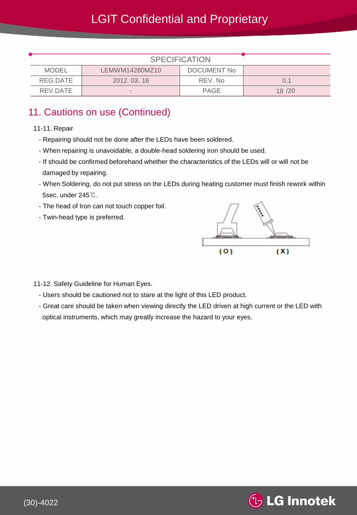
11-11. Repair
- Repairing should not be done after the LEDs have been soldered.
- When repairing is unavoidable, a double-head soldering iron should be used.
- If should be confirmed beforehand whether the characteristics of the LEDs will or will not be
damaged by repairing.
- When Soldering, do not put stress on the LEDs during heating customer must finish rework within
5sec. under 245℃.
- The head of Iron can not touch copper foil.
- Twin-head type is preferred.
11-12. Safety Guideline for Human Eyes.
- Users should be cautioned not to stare at the light of this LED product.
- Great care should be taken when viewing directly the LED driven at high current or the LED with
optical instruments, which may greatly increase the hazard to your eyes.
18

(30)-4022
SPECIFICATION
MODEL LEMWM14280MZ10 DOCUMENT No
REG.DATE 2012. 03. 16 REV. No 0.1
REV.DATE - PAGE /20
LGIT Confidential and Proprietary
12. Reflow Soldering Characteristics12-1. Soldering Conditions.
- The LEDs can be soldered in place using the reflow soldering method.
- LG Innotek cannot make a guarantee on the LEDs after they have been assembled using dip
soldering method.
- Recommended soldering conditions.
- Pb Solder
- Pb-free Solder
- Although the recommended soldering conditions are specified in the above diagram, reflow or
hand soldering at the lowest possible temperature is desirable for the LEDs.
- A rapid-rate process is not recommended for cooling the LEDs down from the peak temperature.
- Occasionally there is a brightness decrease caused by the influence of heat of ambient
atmosphere during air reflow. It is recommended that the customer use the nitrogen reflow method.
- The encapsulated material of the LEDs is silicone, Therefore the LEDs have a soft surface on the
top of the package. The pressure to the surface will be influence to the reliability of the LEDs.
Precautions should be taken to avoid the strong pressure on the encapsulated part. So When using
the chip mounter, the picking up nozzle that does not affect the silicone resin should be used.
- Reflow soldering should not be done more than two times.
19

(30)-4022
SPECIFICATION
MODEL LEMWM14280MZ10 DOCUMENT No
REG.DATE 2012. 03. 16 REV. No 0.1
REV.DATE - PAGE /20
LGIT Confidential and Proprietary
12. Reflow Soldering Characteristics
12-2. Soldering Iron
Basic spec is ≤3sec when 350℃. If temperature is higher, time shorter (+10℃ -1sec). Power
dissipation of Iron should be smaller than 15W, and temperature should be controllable. Surface
temperature of the device should be under 230℃.
20