structural © - defense technical information center · distribution/availability of report...
TRANSCRIPT
«K.JPJÜÖ ■
" ' ""© COMPUTER-AIDED STRUCTURAL ENGINEERING (CASE) PROJECT
TECHNICAL' RGPÖRI ITL-89^5
CCHAN^RUeTURAL DESIGN OF- RECTANGULAR CHANNEil ACCORDING TO CORPS OF ENGINEERS :. CRIT|RIA FOR HYDRAULIC STRUCTURES
I COMPUTER PROGRAM X0097 {
"'.'•'■■■'■': ■'■:;|,.'■'" -.; . '.■',,.'■ "y :'"■■> • ' ;-"\ r''.■■■■■/"''■' . ■. x f William A. Price ■
^Information Technology Laboratory . -.
I DEPARTMENT OF THE ARMY/ ^™-%s Experiment Station, Corps of Engineers
I 3909 Halls Ferry Road fyicksburg, Mississippi 39180-6199
:'."' ; EdwiivS. Ailing,
♦V DEPAR"PMENT OF 'AGRICULTURE ■ ■■ 1. Son Conservation Service
/Hyattfcvilfe, Maryland \
'
DTIC
. August 1989 > \\-, ^ F^natReport/
Approved For Public Release. Distribution Unlimited
Prepared for DEPARTMENT pF THE ARMY
• US Army Corps of Engineers ( Washiogtöht DC 20314-1000
Destroy this report when no longer needed. Do not return it to the originator.
The findings in this report are not to be construed as an official Department of the Army position unless so designated
by other authorized documents.
This program is furnished by the Government and is accepted and used by the recipient with the express understanding that the United States Government makes no warranties, expressed or implied, concerning the accuracy, ccmpleteness, reliability, usability, or suitability for any particular purpose of the information and data contained in this pro* gram or furnished in connection therewith, and the United States shall be under no liability whatsoever to any person by reason of any use made thereof. The program belongs to the Government. Therefore, the recipient further agrees not to assert any proprietary rights therein or to represent this program to anyone as other than a Government program.
The contents of this report ore not to be used for advertising, publication, or promotional purposes. Citation of trade names does not constitute on official endorsement or approval of the use of
such commercial products.
...
·•·
THIS DOCUMENT IS BEST QUALITY AVAILABLE. THE COPY
FURNISHED TO DTIC CONTAINED
A SIGNIFICANT NUMBER OF
PAGES WHICH DO NOT
REPRODUCE LEGIBLY,
KfljiüTv aMiteMif ^dTHi^TCgr
REPORT DOCUMENTATION PAGE F{HO\ ApptOW9Q om m 07044m
1«. REPORT SECURITY CLASSIFICATION
ilnrlfliilHfifl »mi i n^^— 2«. SECURITY CLASSIFICATION AUTHORITY
2b. OECLASSIFICATION/DOWNGRADING SCHEOULE
lb. RESTRICTIVE MARKINGS
3. DISTRIBUTION/AVAILABILITY OF REPORT
Approved for public release; distribution unlimited
4 PERFORMING ORGANIZATION REPORT NJMIER(S) S. MONITORING ORGANIZATION RIPORT NUMBEK(S)
ffL-8?-? ORGANIZATK
Technical faffs-rt U. NAME OF PERFORMING ORGANIZATION
USAEWES. Information Technology Laboratory
k. ADDRESS (Oty, Stf. «fid ZlPCo*)
3909 Halls Ferry Road Vicksburg, MS 39180-6199
«b Of FICI SYMBOL (tf spplkth)
C EWES-IM-DA
7«. NAME OF MONITORING ORGANIZATION
7b. ADDRESS (Oty. Sfatt, *n«*Z«PCooV)
9 PROCUREMENT INSTRUMENT IDENTIFICATION NUMBER U. NAME OF FUNDING/SPONSORING ORGANIZATION
US Army Corps of Engineers •c ADDRESS (Oiy. »SS. *nd /tf»Co*>
8b. OFFICE SYMIOL (If W*<**)
10 SOURCE OF FUNDING NUMBERS
Washington, DC 203H-1000 F-ROGRAM ELEMENT NO.
MOJECT NO
TASK NO.
WORK UNIT (ACCESSION NO
11 TITLE J55G5 Security SSSSIcSSS^ CCHAN—Structural Design of Rectangular Channels According to Corps of Engineers Criteria for Hydraulic Structures; Computer Program X0097
Price. William A. lie TYPE OF REPORT
All|1^-EdWlnSl TIME COVERED
FROM TO
is DAYE OF mm rasraraai w *^ row
1«. SUPPLEMENTARY NOTATION
Available from National Technical Information Service, 5285 Port Royal Road, Springfield, VA MJJd
■CöSTTTTÖÖET U II SUBJECT TERMS WSSmS SS rmnt if Scti»? «ntf E3$ by 8S3 ISSnStfJ
FIELD GROUR SUS-GROUP ChannelsMv^"":* Drainage)
»;) Soil Conservation Service.
laawws Structural design U UN
1* ABSTRACT iContSw« Of» rtVtf»» tf AMfSISfy
■* The computer program CCHAN (X0097) for rectangular reinforced concrete channels, and its companion program CBASIN for stilling basins, were obtained from the Soil Conservation Service (SCS) of the US Department of Agriculture for US Army Corps of Engineers (USACE) use in obtaining preliminary structural designs of important or unusual structures or complete designs of s^all, routine structures. These programs vere adapted to Corps of Engineers criteria for hydraulic structures, and additional output information on member forces and moments was added.
The SCS program document is Included in this report as Appendix A. information in the main text, of this report supplements or supersedes portions of the SCS document. I , /.
20 DtSTRHUTtON/AVANASIUTV Of AISTRACT QUNCIASSIFIEO/UNUMITED Q SAME AS RPT O OTIC USERS
11 AiSTRACT SECURITY CLASSIFICATION Unclassified
21* TEliRHONE iK35 ATM CM I 22c OFF* SYMBOL IU WS<* OF RESPONSIBLE INDIVIDUAL
DO form 1471. JUM M SECURITY flAjSjfjCftTgfl <» THIS PAGE
Unclassified
89 9 18 167
ELECTRONIC COMPUTER PROGRAM ABSTRACT
TITLE OF PROGRAM X0097—CCHAN—Structural Design of SCS Rec-
tangular Channels ArrnrrHnp tn r.V ry-H-oy-fa
PREPARING AGENCY CEWES Information Technology Laboratory
PROGRAM NO. I 713-P-R0099
AUTHOR(S) Edwin S. Ailing George Henson
William A. Price DATE PROGRAM COMPLETED
January 1989
STATUS OF PROGRAM
PHASE STAGE
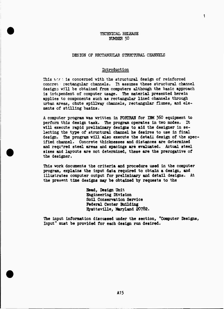
A. PURPOSE OF PROGRAM
To perform preliminary or complete structural designs of U-frame channels according to Technical Release No. 50, "Design of Rectangular Structural Channels"
B. PROGRAM SPECIFICATIONS
The Program uses working stress analysis in accordance with Corps of Engineers EM 1110-1-2101, "Working Stresses."
C METHODS
D. EQUIPMENT DETAILS
CCHAN runs on MS-DOS microcomputers. It does not use graphics. A math coprocessor is not required, but will be used if installed.
E. INPUT-OUTPUT
Tnput is interactive, with prompting. Output is to the screen; use <CtrlXPrtSc> to get hard copy printout.
F. ADDITIONAL REMARKS
A user's guide is available from the Engineer Computer Programs Library, WES telephone (601) 634-2581. This user's guide Includes Soil Conservation Service Technical Release No. 50.
wEs, ::r.o 2205 *C»l»CII IN« FORM !■•» «MICH it OHOUCTI
PREFACE
The computer programs CBASIN and CCHAN were obtained by the US Army
Corps of Engineers (USACE) from the Soil Conservation Service (SCS), US
Department of Agriculture (USDA), for use in preliminary structural designs of
important or unusual structures or complete design of routine structures.
The original program was written by Mr. Edwin S. Ailing, Engineering
Division, SCS, Hyattsville, MD. The program was later adapted to USACE
criteria by Mr. Aiding and Mr. George Henson, Structures Section, US Army
Engineer District, Tulsa.
This project was a task of the U-Frame Basins and Channels Task Group of
the Computer-Aided Structural Engineering (CASE) Project. Current membership
of the CASE project is as follows:
Mr. firyon Bircher, General Chairman, CEMRK-ED-D Mr. George Henson, Chairman, CESWT-ED-DT Mr. Bill James, now retired from CESWD-ED-TS Mr. Scott Snover, SCS, USDA Mr. Tom Wright, CEMRK-ED-DT Mr. Clifford Ford, CESPL-ED-DB Mr. Donald R. Dressler, CEEC-ED Mr. William A. Price, CEWES-IM-DA
Mr. William A. Price, Information Technology Laboratory (ITL), coor-
dinated the work at the US Army Engineer Waterways Experiment Station (WES)
under the supervision of Mr. Paul K. Senter, Assistant Chief, ITL, and Dr. N.
Radhakrlshnan, Chief, ITL. The text of the report was written by Mr. Price,
and Appendix A was written by Mr. Ailing.
Acting Commander and Director of WES was LTC Jack R. Stephens, EN.
Technical Director was Dr. Robert W. Whalin.
Aoeesslon For
"ÜTIS GfUel DT!C TAB Unannounced Juui'.f icMleiL.
»^ a a
By JDlstributloo/
AvailntllUy Ccdf« •Avail ace/er
Special
CONTENTS
PREFACE
CONVERSION FACTORS, NON-SI TO SI (METRIC) UNITS OF MEASUREMENT
PART I: INTRODUCTION
General . . . Capabilities Limitations .
PART II: DATA INPUT GUIDE
PART III: SPECIAL DISCUSSION OF USACE ADAPTATION
Flotation Criteria Concrete Cover Over Reinforcement
PART IV: OUTPUT
APPENDIX A:
APPENDIX B
APPENDIX C
APPENDIX D
APPENDIX E
APPENDIX F
SCS TECHNICAL RELEASE NO. 50 (REV. I) "DESIGN OF RECTANGULAR STRUCTURAL CHANNELS1
SAMPLE CCHAN RUN FOR PRELIMINARY DESIGNS
SAMPLE CCHAN RUN FOR TIF CHANNEL DESIGN
SAMPLE CCHAN RUN FOR T3F CHANNEL DESIGN
SAMPLE CCHAN RUN FOR T3FV CHANNEL DESIGN
SAMPLE CCHAN RUN FOR T1S CHANNEL DESIGN
Page
1
3
4
4 4 4
5
9
9 9
11
Al
Bl
Cl
Dl
El
Fl
CONVERSION FACTORS, NON-SI TO SI (METRIC) UNITS OF MEASUREMENT
Non-SI units of measurement used in this report can be converted to SI
(metric) units as follows:
To Obtain cubic yards per foot 2.508 cubic metres per
metre
feet 0.3048 metres
foot-pounds per foot 4.4482 joules per metre
inches 25.4 millimetres
pounds (force) per square foot
47.83026 pascals
pounds (force) per square inch
6894.757 pascals
pounds (mass) per cubic foot
16.01846 kilograms per cubic metre
square inches 6.4516 square centimetres
CCHAN—STRUCTURAL DESIGN OF RECTANGULAR CHANNELS
ACCORDING TO CORPS OF ENGINEERS CRITERIA
FOR HYDRAULIC STRUCTURES
COMPUTER PROGRAN X0097
PART I: INTRODUCTION
1. The computer program CCHAN (X0097) for rectangular reinforced con-
crete channels, and Its companion program CSASIN for stilling basins» were
obtained from the Soil Conservation Service (SCS) of the US Department of
Agriculture for US Army Corps of Engineers (USACE) use in obtaining prelim-
inary structural designs of Important or unusual structures or complete
designs of small, routine structures. These programs «rare adapted to Corps of
Engineers criteria for hydraulic structures, and additional output information
on member forces and moments was added.
2. The SCS program document is included in this report as Appendix A.
Information in the main text of this report supplements or supersedes portions
of the SCS document.
Capabilities
3. This program performs the calculations for structural design of
rectangular cross-section structural channels In accordance with Corps of
Engineers criteria for working stress design of hydraulic structures. The
configurations are illustrated in Figure 1 of Appendix A, with their loading
conditions shown in Fugures 2, 3, and 4 of Appendix A.
4. Program CCHAN (X0097) accepts as input the overall geometry, water
elevations, and soils parameters, with structural details as determined by the
program. The user cannot change these details.
4
PART II: DATA INPUT GUIDE
5. Data are as defined for, and entered into, the original SCS program
described in Appendix A--except as described below.
6. Data input was converted from the original SCS program's file input
to on-line interactive as a part of converting from mainframe time-sharing to
personal computer hardware. An additional, optional data line was added to
incorporate being able to select basic structural analysis to conform to
(a) the original SCS values, (b) the Corps of Engineers default values, or
(c) any other values. Input prompting messages were expanded to present more
recognizable help to the user. The user is led through data entry, line-by-
line, ms needed. Text examples shown below are as printed by the program.
ENTER FIRST HEADER LINE:
Type in the first line of title information and press the enter key. This
line and the second header line may be up to 80 characters long and should
provide identification of the design being executed. You will now be prompted
for the second title line.
ENTER SECOND HEADER LINE:
Type in the second lira of title information and press the enter key. You
will now be prompted for data line three, required:
ENTER THE FOLLOWING:
Enter the data requested in the order listed, separated by at least one space.
Refer to page 57 of Appendix A for detailed information on the input required.
Press the enter key once all the data items have been typed and arr correct.
These instructions apply to all lines of numeric data.
CL WDTH HGT HGT DESIGN DFLT1 DFLT2 DFLT3 DFLT4 CHANNEL WALL BKFILL PARAH 0-DEF O-DEF 0-DEF 0-DEF
FT FT FT
where
Prompting Messaffe
CL WDTH CHANNEL, HGT WALL, FT HGT BKFILL, FT
FT
Appendix A Nomenclature
B HT HB
Appendix A Elma
1.6 1.2.3.6 1.2.3,5.6
DESIGN PARAM: Use zero to get four preliminary designs, one for each type of channel. or use 1 to get final design of TIF channel. or use 2 to get final design of T3F channel. or use 3 to get final design of T3FV channel. or use 4 to get final design of T1S channel.
DFLT1: Use 1 to get entry of data line four values, or 0 to use default values.
DFLT2: Use 1 to get entry of data line five values, or 0 to use default values.
DFLT3: Use 1 to get entry of data li~ne six values, or 0 to use default values.
0FLT4: Use 1 to get entry of data line seven values, or 0 to use Corps of Engineers default values.
7. When the program prompts for an input line (DFLT#*»1), the entire line
of values must be entered, not just those values that are different from the
defaults. Otherwise, the program will give unpredictable results by reading
erroneous values for the prompted input. Data line four is used only if OFLTl
in line three was entered as 1.
where
WAT HT WAT HT UP HO SOIL WT SOIL WT LAT SOIL LAT SOIL SAFETY LC 1 LC 2 SLAB MOIST SAT PR RATIO PR RATIO FACTOR FT FT FT LB/C? LB/CF LC 1 LC 2 FLOAT
Default Appendix A Appendix A Promoting Messafe Value FUvirt
2.4,5.6 WAT HT. LC 1. FT 0.8 B HW I (LC 1) WAT HT. LC 2, FT 0.1 B HW 2 <LC 2) 3 UP HO, SLAB, FT * UVF » 12 SOIL WT, MOIST, LB/CF 120.0 GMOIST 2.3 SOIL WT, SAT, LB/CF 140.0 GSAT 2.3 LAT SOIL, PR RATIO, LC 1 0.$ K01 5 LAT SOIL, PR RATIO, LC 2 02 K02 5 SAFETY FACTOR FLOAT 1.5 FL0ATR
* HW 1 OR 0.8 of backfill height. LC 1. * Used by T3F and T3FV channels.
Data line five is used only if DFLT2 in data Una three was entered at 1.
MAX FOOT PROJECT FT
SPAN BETN LONG JTS
FT
FOUND MODULUS LB/FT3
where
Prompting Bmiga
MAX FOOT PROJECT, FT SPAN BETN LONG JTS, FT FOUND MODULUS, LB/FT3
Default ValUft
0.5 B *
100,000
Appendix A
MAXFTG JOINTS MF0UND
Appendix A Reference
#
TABLE 1
* Uaed for strutted channel only, see Figure 1 of Appendix A. Default for B -c 10 la 20. Default for 10 < B < 20 is 2.0 B. Default for B >- 20 is 40.
# Limit of FTG, shown in Figures 4, 6, 7, 11 of Appendix A.
Data line five is used only if DFLT3 in data line three was entered as 1.
data items are discussed in Table 1 of Appendix A.
Its
COEFF FRICTION SOIL-CONC
COEFF FRICTION SOIL-SOIL
PASSIVE SOIL PR RATIO
where
fromptlng H«ifMi ,
COEFF FRICTION, SOIL-CONC COEFF FRICTION. SOIL-SOIL PASSIVE SOIL PR RATIO
Default Valttfi 0.35 0.55 *
Appendix A Honnclturt
CFSC CFSS KPASS
* 1.0/K01 - 1.25 if default KOI is used.
Data line six is used only if DFLT4 in data line three was entered as 1
CONCRETE ULTIMATE STRENGTH
PSI
RATIO FC TO F'C
where
Elgjffillni tttftuU- CONCRETE ULTIMA!E STRENCTH. PSI RATIO FC TO F*C ALLOWABLE STEEL STfcESS. PSI ALLOWABLE NET BEAR PRESSURE, PSF MINIMUM CONCRETE THICKNESS. IN
ALLOWABLE STEEL
STRESS PSI
Default Vtlut
ALLOWABLE NET BEAR PRESSURE
PSF
MINIMUM CONCRETE THICKNESS
IN
3000.0 0.35
20000.0 2000.0
12.0
Appendix A
FPC COESF FSA ABP THIN
SCS Vtlut 4000.0
0.4 20000.0 2000.0
10.0
8. After all numeric data have been entered, and If a detailed design
was requested ("DESIGN PARAM" In data line three was entered as not 0), then
the program will ask the question 'IS MOMENT»THRUST.SHEAR REPORT DESIRED?
Enter either Y or N..." Respond with a eaoltsl Y if the report (shown in
Appendixes C through F) is desired or with a capital N if it is not wanted.
PART III: SPECIAL DISCUSSION OF USACE ADAPTATION
Flotation Criteria
9. The original SCS program defined the factor of safety against
flotation SFf as
^ Sum of all forces down £ * Sum of all forces up
When the program was converted to USACE criteria, in accordance with Engineer
Technical Letter (ETL) 1110-2-307, the definition was changed. Figure 1
illustrates the adaptation of ETL 1110-2-307 to channels and transforms the
resulting equation to
SF - Sum of *H forces down - weight of water £ " Sum of all forces up - weight of water
goj&ieja coyer Qyer Reinforcement
10. Concrete clear cover over reinforcing steel was programmed in the
SCS program as being 2 in.* everywhere except for bottom steel in the bottom
slab where it was programmed to be 3 in. The USACE modifications added that
it would be 3 in. everywhere if the data item COESF is less than 0.38. (If
COESF is greater than or equal to 0.38, then the cover is not changed from the
original SCS values.)
* A table of factors for converting non-SI units of measurement to SI (metric) units is presented on page 3.
FLOTATION CHANNELS
Load Condition # 1 controls
V&
-wr
H N I' I*
E2^^^^gg^^^5ESS!2SS51!SIS!£EH5]
mill M i M u
CO z
Per ßTL lll©-e-Jf07
* U-Vv4 ^ U-\
J7*«*> *
v)
4*d 0« JOP
JO
•05 r? „ ■ J
> 5uP-Wi
Figure 1. ETL 1110-2-307 adapted to channels
10
PART IV: OUTPUT
11. Output consists of three parts. Each part has its own heading; the
first two parts, with headings expanded and rearranged for clarity, are as in
the original SCS program described in Appendix A. The third part, produced
with the "YM answer described in paragraph 8, is new.
12. The first part is essentially a summary of the input data. It is
introduced with the printed line
DESIGN PARAMETERS
13. The second part is different for each of the five possible values
for the variable DESIGN PARAM in data line three, according to the following
list:
Channel Illustrated in Appendix A PESIW PARAH 1XM APPEUdlX figure
0 preliminary B * 43 bottom 1 TIF C ** 44 2 T3F D ** 46 3 T3FV E ** 48 4 T1S F ** 50
* Introduced with the printed line "PRELIMINARY DESIGNS FOLLOW" ** Introduced with the printed line "DESIGN OF SPECIFIED TYPE CHANNEL
FOLLOWS" and concluded with the message "END xxx DESIGN," where xxx is the channel type.
14. Part three, if requested as described in paragraph 8, is introduced
by the printed line
MOMENT,THRUST,SHEAR REPORT
It starts with an echo of data lines one and two. This is followed with a
message referring to Figures 29, 33, 36, 39, and 40 of the SCS document in
Appendix A for illustration of location codes. This is illustrated in
Appendixes B through E.
11
APPENDIX A: SCS TECHNICAL RELEASE NO. 50 (REV. 1)
"Design of Rectangular Structural Channels"
Page numbers at top of pages are as In the original Soil Conservation Service docu- ment. Page numbers at bottom of pages in this appendix are for this document.
U. S. Department of Agriculture Soil Conservation Service Engineering Division
Technical Release No. Design Unit July 1977
50 (Rev. 1)
DESIGN OF RECTANGULAR STRUCTURAL CHANNELS
A3
DEFACE
This technical release continues the effort to produce design aids which facilitate the attempt towards optimization of structural design. Three earlier technical releases, TR-^2, TR-JO, and TR-^5> deal with the structural design of rectangular conduits« This technical release is concerned with the structural design of rec- tangular channels. Although primarily written for design engineers, the material has considerable application for planning engineers since preliminary designs of structural channels are readily avail- able to them*
A draft of the subject technical release dated August, 1971, was sent to the Engineering and Watershed Planning Unit Design Engineers for their review and comment.
This technical release was prepared by Mr. Edwin S. Ailing of the Design Unit, Design Branch at tyattsville, Maryland. He also wrote the computer program.
A5
TECHNICAL RELEASE NUMBER 50
DESIGN OF RECTANGULAR STRUCTURAL CHANNELS
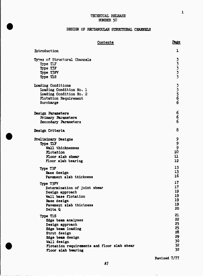
Contents Beige
Introduction
•fy^es of Structural Channels 3 Type TIF 3 Type T3F 3 typ« T3FV 3 Type TLS 3
Loading Conditions 3 Loading Condition No. 1 3 Loading Condition No. 2 5 Flotation Requirement 6 Surcharge 6
Design Parameters 6 Primary Parameters 6 Secondary Parameters 6
Design Criteria 8
Preliminary Designs 9 Type TIF 9
Wall thicknesses 9 Flotation 10 Floor slab shear U Floor slab bearing 12
Type T3F 13 Base design 13 Pavement slab thickness 1&
Type T3FV IT Determination of Joint shear IT Design approach 19 Wall base flotation 19 Base design 19 Pavement slab thickness 19 Delta Q 20
Type T1S 21 Edge beam analyses 22 Design approach 25 Edge beam loading 25 Strut design 28 Edge beam design 29 Vail design 30 Flotation requirements and floor slab shear 32 Floor slab bearing 32
Revised 7/TT
A7
ii
Detail Designs 33 Floor Slab Analysis 33
Deflection, shear, and moment due to NW 3^ Deflection, shear, and moment due to MW 35 Deflection, shear and moment due to uniform loading, q 36 Deflection, shear, and moment due to ^ and MQ 37 Solution for 0^ and MQ W
' 37 Solution for finite beam 38
ütype TIF Ü Wall steel M Floor slab steel ^
Tirpe T3F ^5 Sliding stability of base ^5 Base slab steel ^7 Pavement slab steel ^8
Type T3FV ^9 Shear Joint requirements ^9 Base slab steel 50 Ävement slab steel 51
!type T1S 53 Wall steel 5^ Floor slab steel 5^ Edge beam steel 5^ Edge beam stirrups 55
Computer Designs 57 Input 57 Output 57
Preliminary designs 58 Detail designs 58
Type TIF 58 Type T3F 58 Type T3FV 58 Type T1S 58
A8
ill
Figures Page
Figure 1 Structural channel types. k Figure 2 Load condition No. 1. 5 Figure 3 Load condition No. 2. 5 Figure h Flotation conditions. 6 Figure 5 Thickness TB for LC#1 when HB > HW1. 9 Figure 6 Flotation condition, LC#1 when HB > HW1. 11 Figure 7 Bearing pressures, LC#1 when HB > HW1. 1^ Figure 8 Investigation of footing shears. 15 Figure 9 Pavement slab flotation, type T3F. 16 Figure 10 Joint shears in type T3FV channels * 17
Figure 11 Base pressures concerned with joint shears. id Figure-12 Ävement slab flotation, type T3JV. 19 Figure 13 Definition sketch, type T1S channel. 21 Figure Ik Passible atrut-to-wall connections. 22 Figure 15 Edge beam loading and displacement. 22 Figure 16* Type T1S frame displacements, typical loading. 22 Figure 17 Alternate method of solution for edge beam analyses. 23 Figure 18 Evaluation of frame U and n. 2$ Figure 19 Vertical forces involved with frame T and m, LC#2 when
HB > HW2. 26 Figure 20 Floor slab loads and moments for frame T and m. 27
Figure 21 Sense of positive edge beam loading. 28 Figure 22 Edge beam section. 29 Figure 23 Shear at top of wall| LC#1 when HB > HW1, HEB < EB/12,
and HW1 < HT - EB/12. 30 Figure 2k Shear and moment at bottom of wall, LC#1 when HB > BW1. 31 Figure 25 Finite length beam and loading. 3^ Figure <£ Uniform loading cases, Infinite beams. 36 Figure 27 Qo »nd MQ loadings, infinite beam. 37 Figure 2d Corrections for Indicated tensile reactions. 38 Figure 29 Type TIF steel layout and point locations. kl Figure 30 Wall steel design for LC#1, HB > Wl, and Z > HIV. k*
Figure 31 Floor slab analysis and loadings for LC#1 when HB < HW1. U3 Figure 32 Determination of form of shear and moment computations. kk Figure 33 Type T3F steel layout and point locations. U5 Figure 3^ Sliding of type T3F retaining wall portion. k6 Figure 35 Contact pressure distribution for LC#2. kf Figure 36 iype T3FV steel layout and point locations. 49 Figure 37 Direct tension through shear joint for LC#2. 50 Figure 38 Pavement design for LC#1, Ql > 0. 51 Figure 39 Type T1S steel layout and point locations. 53 Figure kO Elan of edge beam, steel layout and point locations. 54
Figure 1*1 Blge beam loading for LC#1 when HXL > 0. 55 Figure ±2 Layout of edge beam stirrups. 50
A9
iv
Figure k$ Computer output, preliminary designs. Figure kk Computer output, type TIF detail design. Figure is-5 Computer output, type TIF detail design. Figure k6 Computer output, type T3F detail design. Figure k7 Computer output, type T3F detail design. Figure k& Computer output, type T3FV detail design. Figure k$ Computer output, type T3FV detail design. Figure 50 Computer output, type T1S detail design. Figure % Computer output, type T1S detail design.
59 60 61 62 63 6k 65 66 61
Tables
Table 1 Secondary parameters and default values. Table 2 Input values per design run.
7 57
A10
NOMENCIATUBE
Not all nomenclature is listed* Hopefully! the meaning of any un- listed nomenclature may be ascertained from that shown.
A s required reinforcing steel area ACOMP s required compressive steel area in strut AS s equivalent edge beam steel area per foot width AG s gross area of strut ATMS s required tensile steel area ia ELS strutj required tensile
steel through T3JV shei\r joint
AV = area of web steel, equals twice bar area a = distance from point A to beginning of load on infinite beam B s clear width of channel BPGR = (B + TB/12) b s width of reinforced concrete member; distance from point A
to end of loading on infinite beam C s JOINTS; distance to extreme fiber
CB 5 direct compressive force in floor slab between walls CF 5 direct compressive force in the footing projection CFSC * coefficient of friction, soil to concrete CFSS 5 coefficient of friction, soil to soil c s distance from point A to left end of load on infinite bean D « effective depth of concrete section; diameter of reinforcing bar E m eccentricity of VHBTj eccentricity of BC due to MD; modulus
of elasticity of concrete EB a width of edge beam ET * thickness of edge beam
e > distance from point A to right end of load on infinite beam FKE3T 5 horizontal force acting on key wall 7I/5ATR x safety factor against flotation PIG m footing projection fc m compressive stress in concrete f8 a stress in reinforcing steel GBÜOT « GSAT - 62.it GMOIST s moist unit weight of backfill GSAT s saturated unit weight of backfill HB a height of backfill above top of floor slab
BBD - (HB - D/12) 3C « (KT - Z3/12) RDIFF - (HB - HWl) or (HB - HW2) EIN s horizontal force of water in channel on retaining wall portion
of channel Hi s components of horizontal load on the wall HKET s additional lateral earth force caused by key wall HR s SUB of resisting horizontal forces on retaining wall portion
of channel HS - (HB + TS/12) ET s height of vail above top of floor slab BEB = (HP - HB)
A11
vi
HTW HW HW1 HW2 HWALL HWD HWP I J JOINTS
J K XD1 K02 KPASS L LC#1 LC#2 M MAXJTG
MB KBP NC MD MB MFOUND MFTG
MOT
Ho
MR
Mr
Ms MSUP
W
WALL
HZ m N NSHT
Ntf
HWALL
= (HT - HW1) = (BW1 + TS/12) s submergence height above top of floor slab for LC#1 s submergence height above top of floor slab for LC#2 s total horizontal loading on the vail = (BW1 - D/12) m uplift head on pavement slab = moment of inertia ■ (PPG + TB/2U) s longitudinal sp&n between transverse Joints
s ratio used in reinforced concrete design s MFOUND s lateral earth pressure ratio for LC#1 m lateral earth pressure ratio for I£#2 s passive lateral earth pressure ratio a span of finite beam s load condition number one a load condition number tvo s bending moment at section under investigation s maximum acceptable footing projection
simple moment due to FOR on B simple moment due to FOR on BKrR (WALL + MPTG) maximum dead load moment in strut equivalent edge beam moment per foot width modulus of the foundation moment at junction of stem vail and footing projection due to loads on footing projection key vail design moment overturning moment about toe of retaining vail portion of channel; ficticious moment at ends of finite beam on elastic foundation (MBP - MB)
resisting moment about toe of retaining vail portion of channel equivalent moment, moment about axis at the tension steel supplemental moment added to end of finite beam vhen 0 < ZFOS i J simple moment due to water in channelj moment applied to floor slab at vail moment at Junction of stem vail and footing projection due to loads on vail moment in vail at Z below top of wall T/U, US frame constant direct force at section under investigation assumed direct compressive force in pavement slab due to water in channel concentrated load applied to floor flab at wall
s direct force brought by the wall to the floor slab of T1S
channel
A12
vii
= BC/RX * RC/RY 3 direct force In veil at Z below top cf wall s l/u, T1S frame constant ^ lntergranular bearing pressure; foundation pressure s bearing (contact) pressure at toe of retaining wall base * EL for LC#1 s bearing (contact) pressure at heel of retaining wall base
FB s uniform loading on floor slab between walls FD 3 bearing (contact) pressure at D from face of support FF s bearing (contact) pressure at face of support; uniform load-
ing on footing portions of floor slab PFPG 2 overburden pressure on footing projection K»R x gross pressure on T1S floor slab PS s uniform loading causing shear in floor slab FUF s uplift pressure on bottom of slab Pt m temperature and shrinkage steel ratio Q a shear transmitted across the joint between pavement slab and
retaining vail base of T3PV channel 01 a Q for LC#1
QQ X ficticious shear at eotXn of finite beam on elastic foundation QSUP x supplemental shear added to end of finite beam when
0 < ZK)6 * J q x uniform loading on Infinite beam R x ratio of downward forces on channel to the uplift forces RC s maximum compressive force in strut maximum RS x edge beam reaction provided by strut RSI « RS for IC#1 RT x maximum tens He force in strut RX x edge beam loading; correction factor for long column buckling
about X axis KXL x RX f or LC#1
RX1MAX x maximum value of any RJQ RXLKXH x minimum value of any RX1 RT x correction factor for long column buckling about T axis S x maximum allowable spacing of reinforcing steel SB x width of strut ST x thickness of strut S2 x maximum allowable spacing of steel at Z below top of wall T a thickness of section under investigation; displacement at top
of T1S frame with stru s removed TB x thickness of bottom of w 01 at floor slab TKEf x thickness of key wall
TP a thickness of pavement slab TS a thickness of floor slab or base slab TT a thickness of top of wall t a thickness of frame at y U x displacement at top of T1S frame due to unit loads u a flexure! bond stress in concrete
A13
viii
V a shear force at section under investigation VD 5 shear force at D from face of support VE s buoyant weight of soil beneath retaining vail base in depth ZKEY
VF a shear force at face of support VHET a sum of vertical forces including uplift VPR z shear carried by web steel VZ s shear in wall at Z below top of wall v s shear stress in concrete W 5 width of a retaining wall portion of T3F or TJFV channel WO s overall width of channel VP a bearing pressure at end of pavement slab WEI s WP for IXtfl WRT a reaction at top of wall X a toe length of T3F and T3FV walls; reference edge beam
coordinate
XD » (X - D/12) XF * (X + TB/12) XP a width of pavement slab between retaining wall bases x a distance from point A to element of load on infinite beam Y a displacement; distance from center of retaining wall base
to point under investigation YD - (W/2 - XD) YF - (W/2 - X?) Y0 a displacement at load point in alternate method of edge beam
analysis YX a displacement at Z from end in actual edge beam YZ a displacement at Z from end in alternate method of edge beam
anaylair
y a distance from mid-depth of edge beam to point under considera- tion In frame
Z a distance from VOTT to toe of retaining wall portion of channel; distance from edge of finite beam to point A ZOY a depth of key wall below retaining wall base ZP06 a distance from end of finite beam to point of tero reactive
pressure
a/ a a length parameter in theory of beams on elastic foundations AQ a additional shear required to produce equal vertical displace-
ments each side of Joint Äs a Incremental length along axis of frame ft a vertical displacement 6fc a vertical displacement of retaining wall base at Joint between
pavement slab and retaining wall base ft. a vertical displacement of pavement slab at joint between pave-
ment slab and retaining wall base C(x) a functional relation in theory of beams on elastic foundations 6(x) a functional relation in theory of beams on elastic foundations •(*) a functional relation in theory of beams on elastic foundations t(x) a functional relation in theory of beams on elastic foundations £o a required perimeter of reinforcing steel * a coefficient relating Q to bearing pressure at end of pavement slab
TECHNICAL RELEASE NUMBER 50
DESIGN OF RECTANGULAR STRUCTURAL CHANNELS
Introduction
This v:r: is concerned with the structural design of reinforced concre-c rectangular channels. It assumes these structural channel design3 will he obtained from computers although the basic approach is independent of computer usage. The material presented herein applies to components such as rectangular lined channels through urban areas, chute spillway channels, rectangular flumes, and ele- ments of stilling basins.
A computer program was written in FORTRAN for IM 360 equipment to perform this design task. The program operates in two modes. It will execute rapid preliminary designs to aid the designer in se- lecting the type of structural channel he desires to use In final design. The program will also execute the detail design of the spec- ified channel. Concrete thicknesses and distances are determined and required steel areas and spacings are evaluated. Actual steel sizes and layouts are not determined, these are the prerogative of the designer.
Ibis work documents the criteria and procedure used in the computer program, explains the input data required to obtain a design, and illustrates computer output for preliminary and detail designs. At the present time designs may be obtained by requests to the
Bead, Design Unit Engineering Division Soil Conservation Service Federal Center Building tyattsville, Maryland 20782.
Ibe input information discussed under the section, "Computer Designs, Input" must be provided for each design run desired.
A15
qypes of Structural Channels
Four structural channel types are treated herein. All are assumed symmetrical about the channel centerline in both construction and load- ing. Each channel is designed for the two loading conditions described in the next section and each must satisfy flotation (uplift) require- ments. See Figure 1 for definition sketches. Any one of the four types may be most advantageous for a particular set of design condi- tions. Because of the large number of parameters involved, it is not always readily apparent which type will be best in a given situation.
Tftrpe TIF In this type, the walls and floor slab constitute a reinforced concrete U-shaped rigid frame. The cantilever walls are integral with the floor slab.
Ttoe T3F In this type, the walls are designed as reinforced concrete cantilever retaining walls. The most advantageous toe length, X, is determined in the design. The pavement slab between the retaining wall bases, is independent of the bases except for any thrust imposed on it by the retaining wall bases.
Type T3FV This is similar to type T3F except that the Joints between the pave- ment slab and the retaining wall bases are designed to transmit shear forces and the slab is monolith"':: between these two shear joints. Thus in type T3FV the pavement slab and retaining wall base deflect equally at the Joints.
Type T1S This is similar to type TIF except that two reinforced concrete struts are provided in each longitudinal span between transverse Joints. The struts are located at the first interior quarter points of the longi- tudinal span. Edge beams are provided along the tops of the channel walls. Thus the walls are not simple cantilevers from the base as with the other types, instead they are supported by the edge beam and strut system and by the floor slab.
Loading Conditions
Two loading conditions are considered in the design of structural channels. Parameter values should be selected so that these loading conditions reflect extremes of probable conditions.
Load Condition No. 1 In this loading the channel is empty. The backfill is submerged to a height, HW1, above the top of the floor slab. The backfill is naturally drained, i.e., moist, above HW1. Load condition No. 1 is meant to
Revised 7/77
A17
B
7777777T, 777777777>
TIF
i TRANSVERSE SECTION
'////////A TJF
TRANSVERSE SECTION
7777777777.
TRANSVERSE SECTION c
c/i* 4—
C/2 C/4
TRANSVERSE SECTION LONGITUDINAL SECTION
Figure 1. Structural channel types.
A18
represent conditions following a rapid lowering of the water surface in the channel, but before the water table in the backfill has lowered significantly from a high level. Thus this loading should maximize: lateral soil load, lateral water load, and uplift. The lateral pressure ratio, KD1, should be taken as high as can reasonably be expected.
uplift
moist lateral earth load
buoyant lateral earth load
Figure 2. Load condition No. 1.
Load Condition No. 2 In this loading the channel is full of water to +he top of the wall and the backfill is submerged to a height, IB/2, above the top of the floor slab. Load condition No. 2 is meant to represent conditions following a rapid raising of the water surface in the channel, but before the water table in the backfill has raised significantly from a low level. Thus this loading should minimise lateral soil load, lateral external water load, and uplift. The lateral pressure ratio, KD2, should be taken as low as can reasonably be expected.
moist lateral earth load
uplift buoyant lateral earth load
-lateral water load
Figure 3. Load condition No. 2.
A19
Elotation Requirement The total weight of the structural channel plus all downward forces act- ing on it must exceed the uplift forces by a suitable safety factor under all conditions of loading. The most critical case is load condition No. 1. The flotation safety factor, FLOATR, is selected by the user. Footing projections, FTG, are added, when required, to develop necessary
uplift
Figure k. Flotation conditions,
additional downward forces.
Surcharge Because of the wide variety of possible surcharge loads, surcharge is not included herein as a specific loading. The effects of surcharge can be duplicated to some extent by arbitrarily increasing lateral pressure ratios, unit soil weights, or backfill heights. Increasing unit soil weights or backfill heights should be done cautiously when the surcharge is applied only intermittently.
Design Parameters
There are some seventeen independent design parameters involved in the design of the aforementioned structural channel types. The design para- meters are classified as either primary parameters or secondary parameters. Values for primary parameters must be supplied by the user for each design run. Secondary parameters will be assigned default values if values are not supplied by the user. The methods of supplying parameter values are discussed under the section, "Computer Designs."
Primary Parameters HT 5 height of wall above top of floor slab, in ft HB s height of backfill above top of floor slab, in ft 3 s clear width of structural channel, in ft
Secondary forameterg Not all secondary parameters are used by all channel types. The secondary parameters and their default values are listed in Table 1. Usage of these parameters is explained where first encountered. Those parameters having limited use are indicated.
Revised 7/77
A20
<u
ä EH
Pn CO
CO
EH EH
<D
CD H • • OO
oo CVJ §
O O H as H H
pq IAIA* • • HO
\T\ UN KMA
d d
*
o 3
H CM
HCVJ
0)
1 Mi +> *> >
J8.SS 4> e«g o o ffl
ii
H H
555
43 Ä J3
3S
4>
is
S3
II «P -P
55 fit Vi Vi o o
o o
88 o o
ui "i in m w in n IN m m
!
4> 4) Ö «4
0
is »s 4» n «o 3
as
c
s -
8 8 8
A21 Revised 7/77
*c = 1600
V - 70
u
u
= 3>Tfc\/D
=r i*.oV"v/D
= 20,000 = 16,000
10 11
inches inches
Pt p+
* 0.001 = 0.002
Design Criteria
Materials Class Ji-000 concrete and intermediate grade steel are assumed.
Working Stress Design Design of sections is in accordance with working stress methods. The allowable stresses in psi are
Extreme fiber stress in flexure
Shear, V/bD*
flexura1 Bond tension top bars
other tension bars
Steel in tension in compression, axially loaded columns
Minimum Slab Thicknesses Walls Bottom slabs
Temperature and Shrinkage Steel The minimum steel ratios are
for unexposed faces for exposed faces
Slabs more than 32 inches thick are taken as 32 inches.
Web Reinforcement The necessity of providing some type of stirrup or tie in the slabs be- cause of bending action is avoided by
(1) limiting the shear stress, as a measure of diagonal tension, so that web steel Is not required, and
(2) providing sufficient effective depth of sections so that compression steel is not required for bending*
Cover for Reinforcement Steel cover is everywhere 2 inches except for outside steel in bottom slabs where cover is 3 inches.
Steel Required by Combined Bending Moment and Direct Force Required area determined as explained on pages 31 - 3^ of TR-^2, "Single Cell Rectangular Conduits - Criteria and Procedures for Structural Design."
Spacing Required by Flexural Bond Spacing determined as explained on page hf of TR-42,
Spacing of Reinforcement The maximum vermissible spacing of any reinforcement is 18 inches.
* Shear sometimes critical at D f:^m face, sometimes at face, see page 17 of TR-^2.
A22
Preliminary Designs
Trial concrete thicknesses are determined for various critical dimen- sions and preliminary concrete volumes are computed during the prelimin- ary design phase of structural channel design. These quantities may be increased during detail design if computations for required steel areas and spacings indicate thicknesses are inadequate« Assumptions, criteria, and procedures for the several channel types are discussed below. Topics applicable to more than one channel type are presented once when first encountered«
Type TIF Preliminary design of type TIF channels proceeds in an orderly manner. First, required wall thickness at the bottom of the wall, TB, is deter- mined. Then, the channel is checked for flotation and footing pro- jections, JTO, are provided if required. Finally, the floor slab thickness is increased for shear or bearing if necessary.
Wall thicknesses. The wall thickness at the top of the wall, TT, is set at 10 inches. The thickness at the bottom of the wall, TB, is selected as the largest thickness required by: shear for load condi- tion No. 1 (LC#l), moment and direct force for LC#1, shear for LC#2, or moment and direct force for LC#2. Illustrative computatations for a possible case of LC#1 follow.
62.4 x BUI X01 x OBUOY x HM1
XD1 x GHOIST x RDXFF
Figure 5- Thickness TB for LC#1 when KB > ML.
Revised 7/77
A23
10
Let HDIFF = HB - HW1 For any effective depth, D, in inches, let
HWD = HWl - D/12 HBD = HB - D/12
Then the shear, in lbs per ft, at D from face for case shown is:
V = 31.2 x (HWD)2 + KD1 x C»K)IST x HDIFF x (0.5 x HDIFF + HWD) + 0.5 x KOI x GBUOY x (HWD)2
where GBUOY = GSAT - 62.4 is the buoyant weight of the backfill, in pcf
V V V 00 D = vb = 70 x 12 =TO An iterative process is required since the assumed D must agree with the computed required D. When the correct value of D is obtained, the thickness, T, at D from the face is
T = D + 2.5
and the thickness, TB, as required by shear is
TB = 10 + (T - 10) x HT/(HT - D/12).
The bending moment at the bottom of the wall is, in ft lbs per ft
M * 10.4 x (HWl)3 + 0.5 x K01 x GM0IST x (HDIFF)2 X (HD3JF/3 + HWl) + 0.5 x KD1 x GM0IST x HDIFF x (HWl)2 + 0.5 x KOI x GBUOY x (HWl)3/3
The direct compressive force due to the wall, in lbs per ft, for a bottom thickness, TB, is
N » 6.25 x HT x (TP + TB)
The equivalent moment, Mg, is
Ma * M + N x (0.5 x TB - 2.5)/l2
So the required bottom thickness for balanced working stress conditions is
TB • (O.OO3683 x Mg)x/2 + 2.5
An Iterative process is again required since the assumed TB must agree with the computed required TB.
Computations are similar for LC#2. The largest required thicknesr con- trols.
Flotation. As previously noted, I£#l is critical with regard to flotation« For the case shown in Figure 6, the pressure, in psf, on the footing pro- jections is
JTOJ » GM0IST x HDIFF ♦ GSAT x HWl
the uplift pressure, in psf, for a floor slab thickness, TS, in inches, is
PUP - 62.4 x (HWl ♦ TS/12)
the overall width of the channel, in ft, is
WO » B ♦ 2(FIC ♦ TB/12)
A2k
11
Hence the ratio, R, of the downward forces on the channel to the up- lift force is
_ 2(N + PFTG x FTG) + 12.5 x TS x WO " BSP x WO
R =
where N = 6.25 x HT x (IT + TB). This ratio must not be less than the flotation safety factor, FLQATR.
The initial value of TS is TS = TB + 1 and the initial value of FTG is zero. If R < FLQATR, then FTG is set at 1.0, if again R < FLQATR, then FTG is incremented by 0.£ ft and another attempt is made. This process is continued, if necessary, until FTG = MAXFTG, then TS is in- cremented by 1.0 inch until TS = TB + 10. If the flotation criteria is still unsatisfied, the design is abandoned, and a cancellation message is given.
Floor slab shear. Shear will sometimes govern the required thickness of the floor slab. For load condition No. 1 the compressive wall forces and the pressure on the footing projections are the only loads producing shear in the floor slab. ITje uniform loading, in psf, caus- ing shear is
PS = 2(N + PFTG x PTG)/W0
The required floor slab thickness due to shear is obtained from an ex- pression for shear stress at D from the face of the wall, or using 3.5 inches as distance to center of steel
TS * (0.5 x PS x B)/(840 + PS/12) + 3-5
Occasionally I£#2 may be more critical than LC#1. The same expression may be used to obtain a required TS, however PTOr and PS must be re- computed for LC#2 with PS taking account of the floor pressures due to the water in the channel. Thus
PS m 62.^ x HT - (62.1* x OT x B + 2(H + PFTG x FTG))/W0.
If PS % 0, ao further computations for TS are necessary since LC#1 is the more critical.
übte that in the above expression for TS, from a theoretical viewpoint, 2.5 could sometimes be used instead of 3.5• To avoid confusion, 3*5 is always used to get these values of required TS for shear.
.1 W777777T" wm
an J_l
KB
TS
Figure 6. Flotation condition, IC#1 when HB > Htfl.
A25
12
Floor slab bearing. As explained at the end of the section, "Detail De- signs, Floor Slab Analysis," it is sometimes necessary to increase the floor slab thickness to eliminate negative displacements under the center of the floor slab. The theory involved is somewhat complex, its presen- tation is delayed until detail designs are discussed.
Revised 7/7?
A26
13
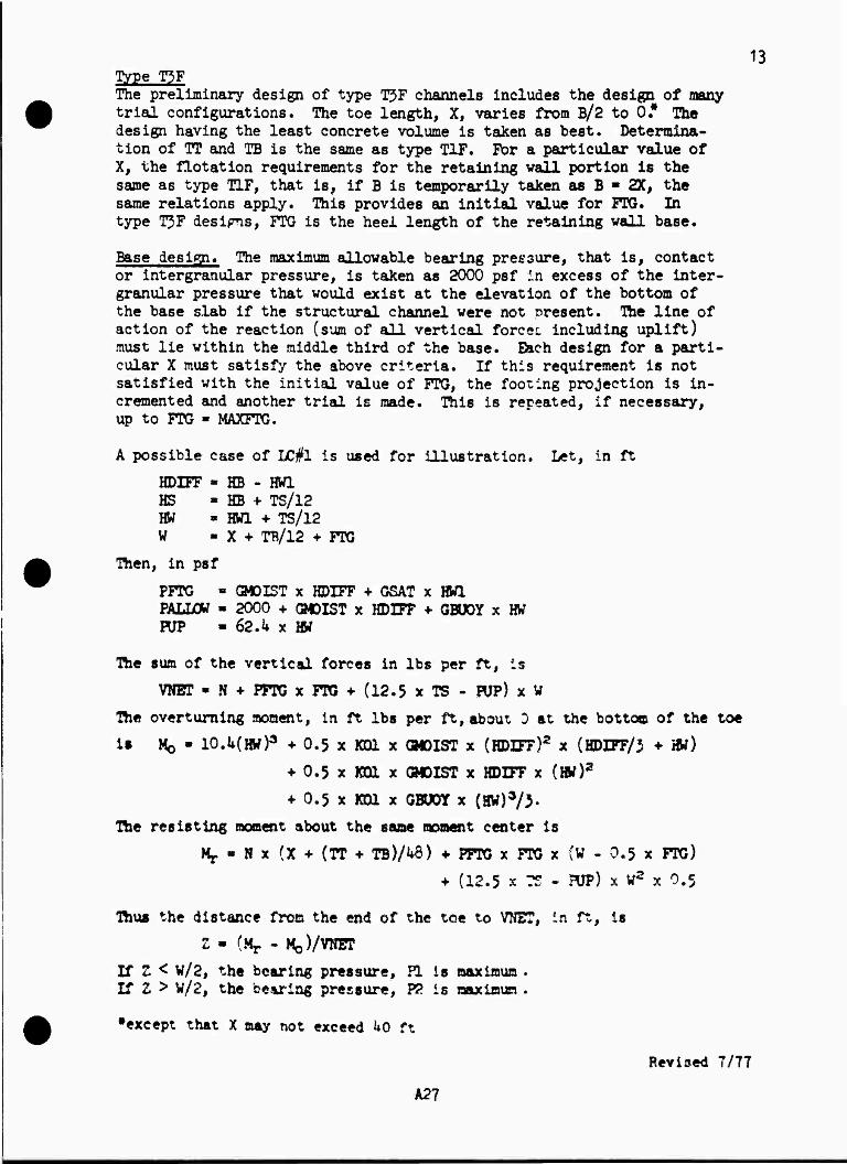
The preliminary design of type T3F channels includes the design of many trial configurations. The toe length, X, varies from B/2 to 0.* Ike design having the least concrete volume is taken as best. Determina- tion of IT and TB is the same as type TIF. For a particular value of X, the flotation requirements for the retaining wall portion is the same as type TIF, that is, if B is temporarily taken as B ■ 2X, the same relations apply. This provides an initial value for ITC. In type T3F desipis, FTG is the heel length of the retaining wall base.
Base design. The maximum allowable bearing pressure, that is, contact or intergranular pressure, is taken as 2000 psf in excess of the inter- granular pressure that would exist at the elevation of the bottom of the base slab if the structural channel were not present. The line of action of the reaction (sum of all vertical forces, including uplift) must lie within the middle third of the base. Each design for a parti- cular X must satisfy the above criteria. If this requirement is not satisfied with the initial value of FTG, the fooling projection is in- cremented and another trial is made. This is repeated, if necessary, up to FTG ■ MAXFTG.
A possible case of IC#1 is used for illustration. Let, in ft
HDIFF » HB - HW1 HS - HB «■ TS/12 HW » HW1 + TS/12 W « X + TB/12 + FTG
Then, in psf
PFTG « O40IST x HDIFF ♦ GSAT x HOT. PALIW « 2000 + GMDIST x HDIFF + QBUOY x HW PUP « 62.4 x HW
The sum of the vertical forces in lbs per ft, is
VNET * N + PFTG x FTG ♦ (12.5 x TS - HJP) x W
The overturning moment, in ft lbs per ft, about 3 at the bottom of the toe
is Mo - lO.MHW)3 + 0.5 x KOI x GM0IST x (HDIFF)2 x (HDIFF/3 * HW)
♦ 0.5 x K01 x GM0IST x HDITF x (HW)2
+ 0.5 x KD1 x GBÜ0Y x (HW)3/3.
The resisting moment about the same moment center is
^ - N x (X + (TT + TB)/U6) + PPTO x FTG x (V - 0.5 x FTG)
♦ (12.5 x ?S - HJP) x W2 x 0.5
Thus the distance from the end of the toe to VN2T, in ft, is
Z • (Mj. - MQVVNET
If Z < W/2, the bearing pressure, PI is maximum . If Z > W/2, the bearing pressure, P2 is aaximun .
•except that X may not exceed ho ft
Revised 7/77
A27
m
Now, in ft, the eccentricity of VNET, is
E = W/2 - Z
If |E| > W/6, the shape of the pressure diagram is unacceptable.
»PCI ♦ 6 x |E|/W) > PALLOV the maximum bearing pressure is too high*
If
HDIFF
EW1
TS
where Z < V/2
HB HW
HS
VNET
n
where Z > V/2
VNFT
Figure 7* Bearing pressures. I£#l when KB > Htfl.
A2£
15
When bearing and pressure distribution requirements are satisfied, base thicknesses required for shear are determined. For LC#1, shear is in- vestigated in the toe at distance D from the face of the support and in the heel at the face of the support. Several situations are possi- ble in determining shear in the toe at D from the wall. Figure 8 illus- trates one possibility in which X > D and Z < W/2.
PL
XD =rr^Uii FJTG
iVP
Figure 8. Investigation of footing shears.
Now D - TS - 5.5 XD - X - D/12 H> « W/2 - XD
Ttoen, in psf
PI « 2£E{1 * 6 x #V)
PD » 2p<l ♦ 12 x E x YD/(W x V))
So the shear, In lbs per ft, at D from the face is
VD » (0.5(P1 «■ HD) ♦ HJP - 12.5 x TS) x XD
A29
16
To get the shear in the heel at the face of the support, let
XF = X + TB/12 then
then
and
So
YF - W/2 - XF
™*'l - 6 x E/W)
+ 12 x E x YF/(W x W))
VF = (PFTG + 12.5 x TS - POP - 0.5(P2 + FF)) X FTG
The required thicknesses for these shears are
TS = VD/840 + 3.5 and
TS ■ VF/840 + 2,5 If either of these values exceeds the current TS, it is Increased accordingly«
Computations are similar for LC#2. The water In the channel must be included in obtaining VHET and the resultant moments. Shears are In- vestigated in the toe at the face of the support and in the heel at D from the face of the support.
Pavement slab thickness. In type T3F channels, the pavement slab is independent of the retaining wall portions of the channel. The pave- ment slab must therefore satisfy flotation requirements independently. Ike uplift head on the pavement slab is HWP. The uplift head could have been made a function of HW1, the same as for the retaining wall portions* However, it was felt that it should be possible to take account of drainage systems, etc. that might be built into the pavement« Nöte that HPP is measured from the bottom of the pavement slab, not from the top of the slab as is the case with HW1 and HW2. TLais the re- quired thickness of the pavement slab to satisfy flotation requirements is, in Inches,
TP * 62.4 x fflfP x FUATB/12.5
fc.k HWP
Figure 9« Bivement slab flotation, type T3F.
A30
17 Ifrpe T3FV The preliminary design of each type T3FV channel for a particular toe length, X, is similar to that for type 3?3F channels with one important exception« The joint between the pavement slab and the retaining wall base is designed to transmit shear from one structural component to the other. Thus the pavement slab and the retaining wall base are forced to deflect equally at the joint. Note that the joint is structur- ally a hinge, that is, it will transmit shears and direct forces, but not moments.
Determination of joint shear. An expression giving the shear trans- mitted through the joint may be obtained by equating expressions for the vertical displacement of the pavement slab, 5p, at the joint and for the vertical displacement of the retaining wall base, 6^, at the joint. It is assumed that such vertical displacements are equal to the interfcranular bearing pressure (contact pressure) divided by the modulus of the foundation, that is
8 = P/MFOUND
where 6 = vertical displacement, in ft P s intergranular bearing pressure, in psf MFOUND a modulus of foundation, in pcf
Equating 5p and 5^, note that the term for the modulus of the foundation cancels out, and
*b =
Figure 10. Joint shears in type T3FV channels.
The pressure Pp, in psf, may be considered as that due to Q plus that due to any other loads on the pavement slab. If the pavement slab is treated as a "rigid body," the pressure due to Q is 2Q/XP. This leads to compu- ted values of Q that are larger than actual values. If the pavement slab is treated as an "elastic body," the pressure due to Q is QX, where X is given below. See "Floor Slab Analysis," pages 33 - 30 for development of similar theory and definition of terms
\ ^/cosh gi + cos a/\ ,_ ___ -t X = 2P(sinh ft + sin W> in Per ft
3 - (5184 x K/(B x (TP)3)1'4 , in per ft
6i = ß x XP
A31
18 w
Q
Q/W
FTG
Hü limn Q/W intergranular bearing pressures
MC Q(W/2)(W/2) 3Q I ~ (w)3/l2 " W
2Q/W
Figure 11. Base pressures concerned with joint shears.
Thus Pp - QX + WP
where WP = pavement slab bearing pressure at shear joint, in psf.
Similarly, the pressure P^ may be thought of in two parts, that due to Q and that due to other loads. From Figure 11, noting that PI nay be obtained from relations described with type T3F
Pb = PL - ^Q/W
Thus equating bearing pressures at the shear joint
QX + WP = PL - UQ/W or, in lbs per ft
>X;T7WJ
This expression for Q may be thought of in two rather different ways. First, as presented, in which ?1 and WP are independent of Q, so that the value of Q obtained from the expression is the true, total value of Q transmitted across the joint. Alternately, if El and WP are computed for loads which include an assumed value of Q, the value of Q obtained from the expression is the additional, or £Q required to produce equal vertical displacements. Both concepts are used in the design of type T'FV channels.
Q = (Fl - WP)(; :)
Revised 7/77
A32
19
Design approach. Determination of TO and TB is the same as type TIF. For each value of X, the design cycles, starting with initial values of Ql and Q2 (for LC#1 and LC#2) set equal to zero and continuing until the design stabilizes at constant values of PTC, TS, TP, Ql, and Q2- That is, for Ql = Q2 = 0, the design obtains the required FTG, TS, and TP. Then new Ql and Q2 are computed using the just determined dimen- sions, next new values of FTG, TS, and TP are obtained. Then new Ql and Q2 values are computed, etc. The design usually quickly converges to correct values.
Wall base flotation. The wall base flotation is treated separately from pavement slab flotation, but each must account for Ql. Refering to Figure 6 and the flotation expressions under type TIF and letting B be taken temporarily as B = 2X, if Ql acts upward on the wall base then
R 2x(Ni PFTG x FTG) + 12.5 x TS x WO HJP x WO + 2 x Ql
if Ql is negative, that is, acts downward on the wall base then
p _ 2 x (N + PFTG x FPG) + 12.5 xTSxW0-2xQl PUP x WO
R can not be less than FLOATR. Thus a minimum value of FPG corres- ponding to the current value of Ql may be obtained.
Base desiga. Base design of type T3FV is the same as type T3F except that the appropriate shear, Ql or Q2, must be Included at the end of the toe. Thus for LC#1, the expression for the sum of the vertical loads is
VNET = N + PFTG x FTG + (12.5 x TS - PUP) x W - Ql
Similarly, the expression for shear in the toe slab at D from the face of the support is
VD = (0.5(P1 + H)) + PUP - 12.5 x TS) x XD + Ql
Rivement slab thickness. In type T3FV channels, the thickness may be governed by flotation or by shear due to the Joint shear.
01 XP
t i TP
HIMItllll IM
01
62.h x HW?
Figure 12. Pavement slab flotation, type T3FV.
20
If Ql acts downward on the pavement slab, then required thickness for flotation is
TP - FLOATR x 62.k x HWP x XP - 2 x Ql Lr ~ 12.5 x XP
If, however, Ql is negative, that is, acts upward on the pavement slab, then
Tp FLOATR x (62.**- x HWP x XP - 2 x Ql) 12.5 x XP
Shear within the pavement slab is only caused by the transmitted joint shear, either LC#1 or LC#2 may control. LC#1 is used for illustration. Let
V= |0l|
then, assuming a uniform loading due to Ql of 2V/XP, the effective depth required is
DP = V/(8^0 + 2V/(12 x XP))
If 01 > 0, then
TP = DP f» 2.5
If Ql < 0, then
TP = DP + 3.5
The l^^est of the computed required thicknesses governs.
Deltc- . The computations indicated above, result in a new set of values for H\J7 TS, and TP corresponding to a particular set of values of QX and Q3« The delta Q values are obtained as previously explained r For LC#1
whezv
so
Similarly
AQ1 = (Pll - WE.) x (y^q^)
WP1 = 12.5 x TP - 62.h x HWP + QloldV
Pll is PI for LC#1 including effect of Qlold
^new = <*old + **
AQ2 = (P12 - WP2) x (j-^)
vhezf WP2 « 12.5 x TP + 62.4 x HT - 62.4 x (HW2 + TP/12) + Q20ldx
P12 is H for LC#2 including effect of 02^
thsn if (WP2 + 2 x AQ2/XP) > 0
<*new » <*old + a* however, if (WP2 + 2 x AQ2/XP)< 0, then Q2 is limited to
Q2 = -(12.5 x TP + 62.4 x HT - 62.4 x (HW2 + TP/12)) x XP/2
These new Ql and Q2 values are used in the next design cycle.
A3*»
21
Type T1S The design of type ELS channels is considerably more complex than any of the previous channel types presented. One of the problems involves the determination of the magnitude and distribution of the support pro- vided the walls by the edge beams. Strut locations were selected at
Figure 13. Definition sketch, type T1S channel.
the indicated quarter points of the longitudinal span between trans- verse channel Joints for two reasons. The spacing is architecturally pleasing since the result is equally spaced struts in a long channel. Such spacing causes a considerable reduction in the maximum moments and shears that exist in the edge beams as compared to those that would exist if the struts were placed at the ends of the longitudinal spans. The struts require positive connections to the walls to prevent acci- dental dislodgement from the supporting vail brackets and because often the strut force will be direct tension rather than direct compression.
A35
22
ET A !< i
ÜJ—liJ
•SB
ET 1 Figure 14. Ibssible strut-to-wall connections.
SB
The vail bracket itself may be designed to prevent lateral movement of the struts.
Edge beam analyses. Before proceeding with the preliminary design, the edge beam theory is established. Load is brought to the edge beam by the vertical wall. The magnitude of this load, RX, varies from section to section along the wall. The struts provide the necessary edge beam reactions. The immediate problem is to describe and evaluate the load- ing on the edge beam. This may be accomplished by considering the frame
RX, lbs per ft
of edge beam
+Y
\
1
c/k
C/2
y cA
4X
Figure 15* Fdge beam loading and displacement,
displacements occuring at a typical vertical section in the channel.
o annum imimi Figure 16. Type T1S frame displacements, typical loading.
A36
23
The displacement at the top of the frame isY = T-UxRX where
Y = displacement at top of frame, also displacement of the edge beam, in ft
T = displacement at top of frame with struts removed, in ft
U s displacement at top of frame due to unit horizontal loads at top of frame, in ft per lb per ft
RX s frame reaction provided by edge beam, also load on edge beam due to frame loading, in lbs per ft.
Thus
or RX m T/U - Y/U
RX » m - nY where
m = T/U and n = l/u The frame constants, T, U, m, and n depend on the structural channel dimensions and loading. They are readily determined when needed.
The elastic curve equation for the edge beam is
,d«Y
or letting
HF-J 5 RX =s n - nY dX4
then
1*04 * n/EI
a4! + l*«Y . m/EI dX4
The general solution could be written and the constants of Integra- tion evaluated by applying various boundary conditions* Ibis becomes rather involved and prone to error because of the Interior location of the struts«
Ibe above procedure can be avoided by utilizing a method of solution indicated on pages 15 - 17 of Tiaoshenko's "Strength of Materials, Art n," for the somewhat similar problem shown In Figure 17*
RS RS
C/4 C/2 c/k
i 1 r
Figure 17. Alternate method of solution for edge beam analyses.
A37
2k
Let
*(ßZ) m e~ßZ(cos ßZ + sin ßZ)
Hr(ßZ) = e~ßZ(cos ßZ - sin ßZ)
e(ßZ) = e"ßZ cos ßZ
£(ßZ) = e~0Z sin ßZ
Then solve for QQ and ^ from the simultaneous equations
Qo 5ß 1 + Kßc)
I I
l - e(ßc)
+ *l |i ♦ e(ßc) j * g Ujec/u) + fOc/4)l = c
- M fi . *(ßc)| + S fe(jßcA) + e(ßcA)l -
Having QQ and ^, then for any Z, the deflection YZ, is
YZ=^2L£ U(ß(|cA - z|}) + *(ß(l3CA - z|])l
Qoß 2n
Moß*
♦ (ßZ) + *(ß{C - Z))
- -^—|C(az) + c(ß{c - z})
This expression finds the deflections due to symmetrical loads, RS, act- ing on a finite length beam. To convert to the edge beam problem note that YXL ä c n » 0, or let YX » YZ - Y0 where
*0 = S^ [i + ♦(PC/2)]+ §*• [«(ecA). ♦ •0ecA>]
MoP ~[5(ecA) + ?(jecA)]
The sign of the deflections must also be changed to agree with the coordin- ate orientation shown in Figure 15- Thus
YX = - (YZ - Y0) = Y0 - YZ
The process of obtaining the magnitude and distribution of KX and of obtaining the magnitude of RS proceeds by trial as follows:
Let RXaver ~ m* that is> assume YXaver ■ 0
Then RS = RX aver x C/2
Evaluate YX, due to RS, at a large number of points Compute new YXaVer> ^aver
s a " n^aver* ^ ^
Repeat this process until RS is essentially constant from one :ycle to the next. When constant RS is obtainei, ?orapute RX corresponding to each YX, that is,
RX = m - nYX
A38
25
Design approach» As with most statically indeterminate systems, sizes and dimensions must be known or assumed before the system can be ana- lyzed. Thus an initial set of trial dimensions is needed. Values for this initial set could simply be guessed, or some approximate methods could be used to obtain them. The latter is used herein. However, the approximations are not discussed separately here since what is more important is an understanding of a typical design cycle or iteration.
Design cycles are repeated as often as necessary to obtain a stable set of dimensions. Bach cycle uses current forces to obtain new dimen- sions from which new forces are computed, etc., repeatedly. One design cycle is described below, assuming a set of trial dimensions is already available.
Edge beam loading. The first step in obtaining RX and RS values is to evaluate U and n = l/U, in ft per lb/ft and lb/ft per ft respectively. These values depend solely on the dimensions of the frame. U is com- puted as
.FRAME | FRAME | FRAME 2 2
.. 1 Myds _ l^i MyAs _ 12^* V2^s V El " E^ I " E Zd ts
-3- OJ
+
I "■*m
Figure 18. Evaluation of frame Ü and n.
where E a modulus of elasticity of concrete, in psf y 2 distance fron: mid-support of frame, in ft t 5 thickness at y, in ft £6 2 incremental length along axis of frame, in ft
Next, T and re = T/U in ft and lbs per ft are computed. T is computed as
.FRAME
■\f | FRAME
Myds 12 Y*MyA6 El = E Zd t3
where the terms are as previously defined and
M A average moment over the length Äs, in ft lbs per ft
LC#2 is used for illustration. LC#1 is similar, but without the effects
A39
26
of water in the channel. Figure 19 indicates the vertical forces in- volved. The struts have teen removed, but their effective weight is included in the force NWALL.
t
^77777777777777, I
I | |
s
f fifl
Figure 19. Vertical forces involved with frame T and m, IC#2 when HB > HW2.
This force, in lbs per ft, is
NWALL * 150 x B x ST x SB/(lU x C) + 150 x (ET - TT) x EB/lW
and here + 6'25 x OT x (OT + TO)
FPPG = GMOIST x HDIFF ♦ GSAT x HW2
so that FGR, which includes uplift, in psf, is
FGR * (2 x (NWALL + PPPG x PPG) + 12.5 x TS x W
+ 62.U x HT x B)/W - 12-5 x TS
The summation for T over the wall portion of the frame is readily made. Wall moments due to external lateral loads produce a positive displace- ment, T, while wall moments due to internal water produce a negative displacement. The components of loads and moments involved in the summation for T over the floor portion of the frame are indicated in Figure du. The summation say be said to include only the clear distance B/2 iince I is assumed to approach infinity at the Joints.
A concentrated aom^r.t is brought to the floor slab at the Junction of wall stem and footing projection. This moment, MC, is the sum of two moments WALL and MFTG. MWALL is the moment due to the loads acting on the wall stem. MFTG is due to the loads on the footing projection
AfcO
27
and Is
MFTG = 0.5 x BGR x (PTG + TB/2h)2
- EPTG x FTG x 0.5 x (PTG + TB/12)
With reference to Figure 20, the summation for one half of the floor
Tf = (12/E) x(MC-MR + 2x(Mf- MB)/3) x (HR + TS/24) x 0.5 x B/(TS/12)3
where moments are in ft lbs per ft and other terms are as previously defined. Thus the frame displacement constants, ml for LC#1, m2 for LC#2, and n are determined.
TB/2
TS
B/2
62.4 x HT
LI _J ' ' i I 1 L- i ■
MBP = 1/8 x RJR x (BPGR)2
MB «1/8 x K»R x B2
Iff . 1/8 x 62.k x HT x B2
>MC = MWALL J +MFTO
BPQR » B ♦ TB/12
TB/2
MBP
Figure 20. Floor slab loads and moments for frame T and m.
With the frame constants known, the edge beam loadings, RX, and the strut forces, RS, can be computed for I£#l and ££#2 as outlined at the end of the section, "Edge beam analysis." In these computations the stiffness of the edge beam Is reflected by the term 0 which is, Per ft
>W4 _ 3n ,W« »•(w) 12(- •) 1
CEI E X SB x (Bry»' RX values are found for a large but finite number of points along the edge beam span. The signs of REL and RX2 are adjusted so that a posi- tive RX has the meaning shown in Figure 21. It is possible to have values of RX1, RSI, RX2, and RS2 of either sense, that is, positive or negative.
AM
28
RXL > 0 RX2 > 0
IC#2
Figure 21. Sense of positive edge beam loading.
Strut design. With the edge beam loading known, the preliminary design can proceed with the determination of a new set of dimensions. The strut is the first unit re-evaluated.
The strut must be designed to carry direct tension if either strut re- action RSI or RS2 is tensile. Let Hi1, in lbs, be the larger of any such tensile reaction. Dien the required tension steel area, in sq inches, is
ATEHS * RT/20,000
Minimum values for the strut dimensions, in inches, are
ST » B/20 for deflections control in accordance with ACI 909(b)
SB * B/50 for lateral support ir accordance with ACI 906
Also, neither ST nor SB will be taken less than 12 inches« which more than satisfies ACI 912.
The strut must be capable of carrying the maximum compress ive strut reaction, let this be RC, In lbs. In addition to RC, the strut carries its ova dead weight in bending about the horizontal cross sectional axis of the strut. The process of compress Ive design is thus as follows*
Set SB & ST at minimum values. Get dead load moment, in ft lbs:
KD - 0.125 x (150 x ST x SB/144) x B x B
Get eccentricity of RC due to KD, in Inches
B « 12 x MD/RC
Get correction for long column by ACI Bq. (9*?)
RX m 1.07 - 0.006 x (12 x B)/(0.J x ST) % 1.0 « 1.07 - 0.52 x B/ST * 1.0
Get direct compression for short column
HX * RC/RX
Taxe MX, see page *2 of TR-42, as larger of
NX or HX x 0.64 x (!.♦ 4 x 3/S?)
Take compress ive steel area, ACQKP, in sq inches, as larger of
ATMS or 0.CÖL x ST x SB, in accordance with ACI 913(a)
A42
29
Find required gross area of column, AGX in sq inches, from ACI Eq. (3A-1) and ACI lW)3
AGX * (NX - 13600 x ACOMP)/850
Get correction for long columns
m m 1.07 - 0.32 x B/SB * 1.0
Get direct compression for short columns
NY = RC/RY
Find required gross area of column
ACT * (NY - 13600 x AC0MP)/850
Let AG = ST x SB in sq inches If AGX, or AGY, or both, are greater than AG, then ST, or SB,
or both are incremented accordingly and the cycle is re- peated until both AGX *nd AGY are * AG.
Edge beam design. The thickness of the edge beam is established by the requirements for bending moment. This is done on the assumption that veb steel for diagonal tension will be provided when necessary. It should be noted that the edge beam is subjected to unknown amounts of torsion. Hence nominal closed stirrups (say #3 § 12) should be provided even when diagonal tension web steel is not required. Thicknesses re- quired for bending moment are determined at the centerline of the sup- port since moments at midspan are small by construction. A summation
- -3
KB * ST
ET * 2 x SB
EX * TT ♦ 2
Figure 22. Bdge beam section.
process is used to obtain the various shears and raooents of interest because the loading curves assume various shapes.
A*»3
30 Initially EB is set equal to ST. The maximum thickness required for bending is determined. If ET, so obtained, is more than twice EB, EB is incremented and another solution is made for ET. Next the maximum thickness which would be required for shear, assuming no web steel, is computed. If this thickness is more than that required for bending, web steel is required. Required web steel is calculated during detail design. Shears are investigated both left and right of the centerline of the support. When the strut reaction is compressive, shears are assumed critical at D from the faces of the support. When the strut reaction is tensile, shears immediately adjacent to the centerline are assumed critical.
Wall design. The wall must be designed for the most critical conditions that exist at any section along the wall between transverse channel joints. As noted, the edge beam provides a variable support to the wall. In order to control the most critical loadings on the wall during design, the maximum and minimum RX values are found for each load condition. These are RX1MAX, RX1MIN, RX2MAX, and RX2MIN respectively. Required wall thicknesses are found for shear at the top of the wall Just below the edge beam, shear at the bottom of the wall, and moment at the bottom of the wall. Moment near midheight of the wall, of opposite sign to the moment at the bottom of the wall, often exists but is usually of smaller magnitude than the moment at the bottom.
Shear at top of wall, below edge beam. -- The maximum required thickness must be found for both load conditions. Shear is assumed critical at the face of the support, although an argument could be made for D from the support for DC#1 if RSI > 0. LC#1 is used to illustrate one possible
RSI > 0 HTB = HT - HB
WRT = RXLMAX
RSI < 0
-WRT = RXLMIN
l-VF"
\
HTB
77717777;
t I
Figure 23. Shear at top of wall; LC#1 when HB > HW1, HTB < KB/12,
and HW1 < HT - SB/12.
situation. For the situation shown, VF is the shear at the face, in lb lbs per ft
VF = WRT - 0.5 x KOI x GMOIST x (EB/12 - HTB)2
so, in inches TT = (|VP|)/8U0 + 2.5
This is the thickness required at the face of the edge beam. Thus TT, projected to the top of the edge beam, could be taken somewhat smaller when TB > TT. This refinement is considered unwarrented since at this time the required TB is unknown.
kkk
Shear at bottom of wall. -- Shear is critical at D from the face of the support for LC#1 and at the face for LC#2. Since the shear at bottom of the wall is to be maximized, the wall reaction at the top, WET, is set equal to the minimum edge beam loading. LC#1 is used for illustration.
RSI > 0 RSI < 0 WRT = RX1MIN
777777777
31
Figure 2k. Shear and moment at bottom of wall, LC#1 when HB > HW1.
Computations and iterative process are similar to those explained for thickness TB for type TIF channels with the addition of WRT. The shear at D from the face is
V = 31.2 x (HWD)2 + KD1 x GMOIST x HDIFF x (0.5 x HD1FF + HWD)
+ 0.5 x KOI x GBUOY x (HWD)2 - WRT then
D * V/8W)
and, when computed and assumed D values agree
T - D + 2.5 so
TB = TT + (T - TT) x HT/(HT - D/l2)
Moment at bottom of wall. — Moment at the bottom of the wall is maxi- mized by using the smallest vail reaction at the top, hence Figure 2k applies.
The moment expression for LC#1 for the situation shown is the same as for type TIF with the addition of the WRT term, thus
M » 10.4 x (HW1)3 +0.5 x KOI x GMOIST x (HDIFF)2 x (HDIFF/3 + HWl) +0.5 x KOI x GMOIST x HDIFF x (HWl)2
+0.5 x KOI x GBUOY x (HWl)3/3 • WRT x (HT - EB/24)
The direct compressive force is NWALL as given under "Edge beam load- ing." The equivalent moment, Mg, thus is
Mg = M + NWALL x (0.5 x TB - 2.5)/l2
A45
32
The iterative process for TB then proceeds as explained for type TIF channels.
Flotation requirements and floor slab shear. Required footing projec- tions, FTG, and required floor slab thickness, TS, are obtained as ex- plained for type TIF channels with the substitution of NWALL for N to account for the weights of the struts and edge beams.
Floor slab bearing. It is sometimes necessary to increase the floor slab thickness to eliminate negative displacements under the center of the floor slab. The theory is presented in the following section, "Detail De- signs, Floor Slab Analysis."
Revised 7/77
kk6
33 Detail Designs
With the exception of the steel in the edge beams of type T1S channels, detail design is concerned with the determination of requirements for transverse steel, not longitudinal steel.
Each detail design begins with the set of trial dimensions obtained in the preliminary design. Thicknesses are incremented, and the design recycled when necessary, whenever it is determined compression steel would otherwise be required to hold bending stresses to allowable work- ing values. Required steel area and maximum allowable steel spacing are computed at a large number of points in the channel cross section. The points are similarly located and numbered in each structural channel type so that there is little difficulty in changing thought from one type to another. Schematic steel layouts are shown for each type. The actual steel layout is selected by the designer once he knows the steel requirements at the various points. The floor slab steel requirements for type TIF and T1S channels are based on analysis of the floor slab as a symmetrically loaded, finite length beam on an elastic foundation. This theory is presented before discussing the detail design of the four channel types.
Floor Slab Analysis A means of determining the deflection, shear, and moment at any point, A, in the slab is required. This may be done by starting,with the elastic curve equation
EI^£ = P = -KT dX
or letting
kß* = K/EI then
si+ ^ - ° dX4
where
K s MFOUND = modulus of foundation, in pcf
E = modulus of elasticity of concrete, in psf
P = foundation pressure, in psf
I s moment of inertia, in ft4 per ft
ß H (518U x K/(E x (TS)3))1/4, in per ft
TS H floor slab thickness, in inches
The modulus of the foundation, MFOUND, is also known by such names as: coefficient of subgrade reaction, subgrade modulus, coefficient of settlement, and modulus of subgrade reaction. Rather than work through the solution of the differential equation, it is easier to utilize various known solutions for infinite beams and to obtain the desired results by superposition. In Figure 25> solutions for (a) and (b) may be obtained by the procedure previously presented for the edge beam analysis. Loadings (c) and (d) require further development.
31»
NW
PF ^m
nn PB
EXnXETD
NW
MW ?P pF
777777777777? 777777 T
m NW
(a)
4< MW MW
/K (b)
PF PF
nm • 111]
(c)
PB
immun (d)
Figure 25« Finite length beam and loadings.
Deflection, shear, and moment due to NW. Expressions for deflection, shear, and moment are needed when the point A assumes various loca- tions. Let YA, VA, and MA be these quantities in ft, lbs per ft, and ft lbs per ft respectively.
AW
35
When A is at the left end of the beam, i.e. Z =0
YA = ^[»(ßj)+*(ß{L- J}j]
VA = |i[e(ßj) +e(ß{L - j][|
MA = J| (JKPJ) + *(p{L - J}7)
When A is between the left end of the beam and the load, i.e., 0 S Z S J
YA = 2*yp Q(p{j - Z}) + *(ß{L - J - Z})]
VA = f- [e(ß(J - Z}) * 9(ß(L - J - Z})]
m =i§ [*(efJ -z)) + *(ß{L - J - z)0 When A is between the two loads, i.e., J § Z § (L - J)
YA = *£yp [*(ß(Z - J}) + »(ßtt - J - Z))]
VA = f- Q 0(ß(Z - J}) + 0(ß(L - J - Z})]
A m = l| &ß[z _ z)) + *(ß{L " J " Z)D Deflection, shear, and moment due to MW. Expressions for deflection, shear, and moment due to the moment, MW, brought to the floor slab by the wall follow.
When Z = 0
YA = - ^-^-\\{^) - C(ß(L - J})]
VA«-1**
MA = - f- [e(eJ) - e(ßfL - J})]
When OSZU
YA = - SSLLii g(ß(J - Z)) - S(ßU - J - Z}f)
VA = - JäSi-p f(ß{J - Z}) - *(ß(L - J - Z))\
MA = - •§* (e(e(j - z}) - e(ß{L - J - z}j]
When J S Z S (L - j)
YA = %LL£L Q(e{z „ j}) + £((3(1, . J - Z)T]
A49
36
VA =. mjLA Q(ß{z. jj). ,(ß{L. j _ z]q
= f (e(ß[z - JJ) 4-e(ß{L - j - zjjj MA
Deflection, shear, and moment due to uniform loading, q. Before terms for the uniform loadings PB and PF can be obtained, solutions for uni- form loads must be established. These are obtained by integrating the corresponding expressions for a concentrated load. Refer to Timoshenko, pages 6 and 7 for similar material.
Without proof:
J*e((3X)dX = - i 1r(ßX)
/?(ßx)dx = - i Hm)
/*(ßX)dX = - I 9(ßX)
/*(ßX)dX = + i S(fSX')
^h Figure 26. Uniform loading cases, infinite beams.
When A is to left of loading, noting that dN = qdX
b a
YA = Jg »(ex)dx - /§ *(ex)dx = |f [e(ßa) - e(ßbj] J o
similarly
VA = k$ |}(0a) " *(ßbD M = rs E ^(ßa) + ^(ßb^l
When A is wi:-is the loading
e c
and
YA = J"g ♦(ex)dx + /g «(Bx)dz = § [2 - e(ec) - e(ßej] C 0 "" "
VA = j* (*(6c) - KßeTJ
MA -^jQ(ac) + 5(ßeT]
A50
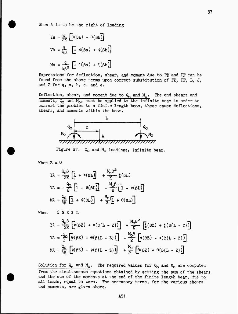
37
When A is to be the right of loading
YA = 2K C9(ßa) ■ 9(ßb3 VA = S E *(ßa) + *(ßbD M = fs E5(ßa) + ^ßbD
Expressions for deflection, shear, and moment due to FB and FF can be found from the above terms upon correct substitution of PB, PF, L, J, and Z for q, a, b, c, and e.
Deflection, shear, and moment due to Qp and ^. The end shears and moments, QQ and MQ, must be applied to the infinite beam in order to convert the problem to a finite length beam, these cause deflections, shears, and moments within the beam.
«0 Qo
"°^ 1* db •777777777777777*7777777777777777777777
Figure 27- Qo and MQ loadings, infinite beam.
When Z = 0
w - Tg E + *(ßL3 + ¥" 5(w,)
VA = - f* [l - 6(PL3 - ^ [l - *(ßlJ)
MA = J| [l ♦ «»]] + ^| + e(pL)]
When 0 S z i L
YA ■ ae t(ßz) + *(eCL " z)0 + TT" 0(ez) + ;(e(L " Z)3 VA =-f°[e(ez) - e(p{L - z))] - ~ [♦(») - »(p(i - z)J]
MA = jj| Q(0Z) + *(ß{L - Z})J + ^ (e(pz) + e(ß{L - Z)j]
Solution for QQ and MQ. The required values for ^ and MQ are computed
fron the simultaneous equations obtained by setting the sum of the shears and the sum of the moments at the end of the finite length beam, due to all loads, equal to zero. The necessary terms, for the various shears and moments, are given above.
A51
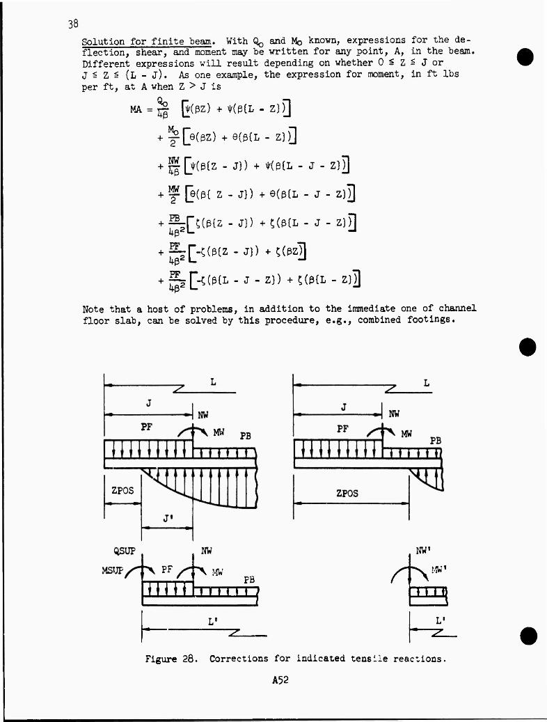
38 Solution for finite beam. With QQ and Mo known, expressions for the de- flection, shear, and moment may be written for any point, A, in the beam. Different expressions will result depending on whether 0 * Z ? J or J^Z^(L-J). AS one example, the expression for moment, in ft lbs per ft, at A when Z > J is
MA = % [HßZ) + *(ß{L - Z}F|
+ ^[e(ßZ) +9(ß{L- Z})]
+ jJQ*(p{z - J)) + Kß(L - J - Z)j]
+ Ä(e(ß( z - j}) +e(ß{L - J - z}T)
+ ^rR(ß(z - J)) + £(ß{L - J - ziH
+ fi[^(ß{z"J)) +^(ßZ3
Note that a host of problems, in addition to the immediate one of channel floor slab, can be solved by this procedure, e.g., combined footings.
nm nm u
NW»
^ MW'
HEB
Figure 28. Corrections for indicated tensile reactions.
A52
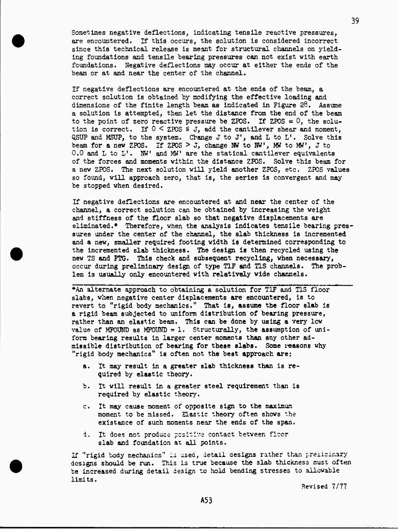
39 Sometimes negative deflections, indicating tensile reactive pressures, are encountered. If this occurs, the solution is considered incorrect since this technical release is meant for structural channels on yield- ing foundations and tensile bearing pressures can not exist with earth foundations. Negative deflections may occur at either the ends of the beam or at and near the center of the channel.
If negative deflections are encountered at the ends of the beam, a correct solution is obtained by modifying the effective loading and dimensions of the finite length beam as indicated in Figure 28. Assume a solution is attempted, then let the distance from the end of the beam to the point of zero reactive pressure be ZFOS. If ZPOS « 0, the solu- tion is correct. If 0 < ZPOS £ J, add the cantilever shear and moment, QSUP and MSUP, to the system. Change J to Jf, and L to Lf. Solve this beam for a new ZPOS. If ZPOS > J, change NW to NVT, MW to MW1, J to 0.0 and L to Lf. KW! and MW' are the statical cantilever equivalents of the forces and moments within the distance ZPOS. Solve this beam for a new ZPOS. The next solution will yield another ZPOS, etc. ZPOS values so found, will approach zero, that is, the series is convergent and may be stopped when desired.
If negative deflections are encountered at and near the center of the channel, a correct solution can be obtained by increasing the weight and stiffness of the floor slab so that negative displacements are eliminated.* Therefore, when the analysis indicates tensile bearing pres- sures under the center of the channel, the slab thickness is incremented and a new, smaller required footing width is determined corresponding to the incremented slab thickness. The design is then recycled using the new TS and PTG. This check and subsequent recycling, when necessary, occur during preliminary design of type TIF and T1S channels. The prob- lem is usually only encountered with relatively wide channels.
*An alternate approach to obtaining a solution for TIF and T1S floor""" slabs, when negative center displacements are encountered, is to revert to "rigid body mechanics." That is, assume the floor slab is a rigid beam subjected to uniform distribution of bearing pressure, rather than an elastic beam. This can be done by using a very low value of MFOUND as MPOUND - 1. Structurally, the assumption of uni- form bearing results in larger center moments than any other ad- missible distribution of bearing for these slabs. Some reasons why "rigid body mechanics" is often not the best approach are:
a. It may result in a greater slab thickness than is re- quired by elastic theory.
b. It will result in a greater steel requirement than is required by elastic theory.
c. It may cause moment of opposite sign to the maximum moment to be missed. Elastic theory often shows the existence of such moments near the ends of the span.
d. It does not produce positive contact between floor slab and foundation at all points.
If "rigid body mechanics" is ased, detail designs rather than preliminary designs should be run. This is true because the slab thickness must often be increased during detail design to hold bending stresses to allowable limits.
Revised 1/11
A53
kA
Tfrpe HF Steel areas and spacings are determined for the twenty two points de- fined in Figure 29. Both LC#1 and LC#2 are investigated. Steel area for temperature and shrinkage is computed and will sometimes control.
21 19
22 20
B/k B/k PTC/2
Figure 29* type TIF steel layout and point locations.
Wall steel. I£#l determines the steel required at the even numbered points in the wall. LC#2 determines the steel at the odd numbered points. One case of ICfl is used for illustration. Tne section under considera- tion is located at distance! Z, from the top of the wall.
For the case illustrated, the following components of shear! in lbs per ft, are computed
VI a 0.5 x GMOIST x RQ1 x (HDIFT)2
V2 a (MOIST x KOI x HDIFF x (Z - ffiw)
V3 » 0.5 x OBUOY x KOI x (Z - EN)2
VU » 0.5 x 62.k x (Z - HTW)2
A55
\2 then
VZ = V1+V2 + V3+VU and, in ft lbs per ft
MZ = VI x (HDIFP/3 + Z - HTW) + V2 x (Z - HTW)/2 + (V3 + Vk) x (Z - HTW)/3
also, in lbs per ft NZ ■ 6.25 x Z x (TT + T)
HBh
Figure 30. Wall steel design for L0#1,- HB > HW1, and Z > HIW.
The required steel area for this MZ and RZ nay be obtained as explained in TR-42. If the current effective depth is inadequate without using COB* pression steel, the bottom thickness, TB, is incremented and the vail steel design is begun again. This process is repeated, as necessary, until TB exceeds its original value by 10 inches. When the effective depth is ade- quate, the required maximum allowable spacing, in inches, is given by
SZ « 10,015 x (T - 2.5)/VZ
as explained in TR-42.
floor slab steel. The floor slab analysis developed earlier is used to obtain shear and moment values from which steel requirements are deter- mined Et the various points in the slab. Either t£#l or L0#2 may govern the steel &t a particular point. One case of tttfl is used to illustrate the computation of the load components on the floor slab.
The vertical wall loading, in lbs per ft, is
HW » 6.25 x HT x (TT + TB)
A56
>3
The various horizontal components of loading on the wall, in lbs per ft, are
HL = 0.5 x GMOIST x XD1 x (HDIPF)2
B2 « GMOIST x KD1 x HDIFP x HW1
H3 = 0.5 x GBUOY x KD1 x (HWl)2
Eh = 0.5 x 62.k x (HWl)2
the total horizontal loading on the wall is
HWALL = HI + E2 + H3 + H^. The moment brought to the floor slab by the wall, in ft lbs per ft, is
MW m ffl. x (HDIFF/3 + HWl + TS/2**) + H2 x (0.5 x HWl + TS/210 + (H5 + H4) x ( HH1/3 + TS/2U)
The direct compressive force in the footing projection, in lbs per ft, is
CF a (KOI x ©CIST x HD3JF + KQ1 x GBUOY x (HWl + TS/2^) « 62.k x (HWl + TS/2*t))x TS/12
The direct compressive force in the floor slab between walls, in lbs per ft, is
CB m CF + HWALL
Figure 31. Floor slab analyses and loading for LC#1 when HB > HWi.
The uniform loadings on the floor slab, in psf, are FB « 12.5 x TS - 62.U x (HWl + TS/12) I* m PB ♦ GMOIST x HDIFF ♦ OSAT x HWl
The floor flab deflections are analyzed and the effective loading and dimensions are modified, in accordance with previous discussion, if negative deflections are discovered at the ends of the slab.
A57
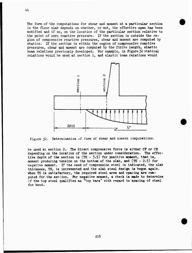
kk
The form of the computations for shear and moment at a particular section in the floor slab depends on whether, or not, the effective span has been modified and if so, on the location of the particular section relative to the point of zero reactive pressure. If the section is outside the re- gion of compressive reactive pressures, shear and moment are computed by statics. If the section is within the region of compressive reactive pressures, shear and moment are computed by the finite length, elastic beam relations previously developed. For example, in Figure 32 statical relations would be used at section 1, and elastic beam relations would
Figure }2. Determination of form of shear and aoment computations.
be used at section 2. The direct compressive force is either CF or CB depending on the location of the section under consideration. The effec- tive depth of the section is (TS - 3.5) for positive moment, that is, moment producing tension on the bottom of the slab, and (TS - 2.5) for negative moment. If the need of compression steel is indicated, the slab thickness, TS, is incremented and the slab steel desijpi is begun again. When TS is satisfactory, the required steel area and spacing are com- puted for the se^ion. For negative moment, a check is made to determine if the top steel qualifies as "top bars" with regard to spacing of steel for bond.
A58
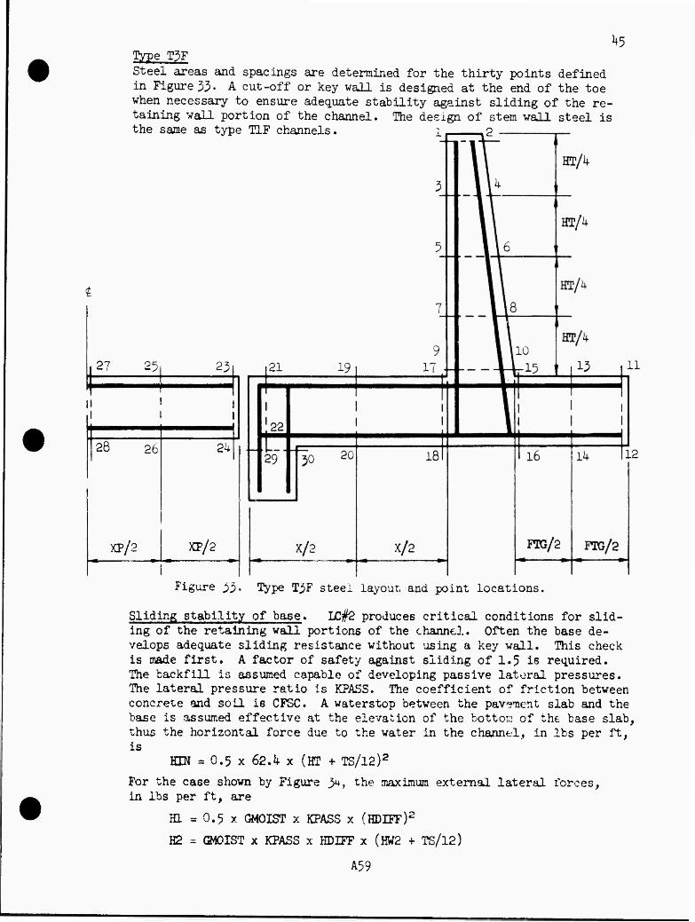
^ Type T3F Steel areas and spacings are determined for the thirty points defined in Figure 33- A cut-off or key wall is designed at the end of the toe when necessary to ensure adequate stability against sliding of the re- taining wall portion of the channel. The design of stem wall steel is the same as type TIF channels. i, .2
27 25.
28 26 2k
XP/2 XP/2
23| 121
Figure 33. Type T3F steel layout and point locations.
Sliding stability of base. LC#2 produces critical conditions for slid- ing of the retaining wall portions of the channel. Often the base de- velops adequate sliding resistance without using a key wall. This check is made first. A factor of safety against sliding of 1.5 is required. The backfill is assumed capable of developing passive lateral pressures. The lateral pressure ratio is KPASS. The coefficient of friction between concrete and soil is CFSC. A waterstop between the pavement slab and the base is assumed effective at the elevation of the bottom of the base slab, thus the horizontal force due to the water in the channel, in lbs per ft, is
HIN = 0.5 x 62.k x (KP + TS/12)2
For the case shown by Figure 34, the maximum external lateral forces, in lbs per ft, are
HI * 0.5 x GMOIST x KPASS x (HDIFF)2
H2 = GMOIST x KPASS x HDIFF x (HW2 + TS/12)
A59
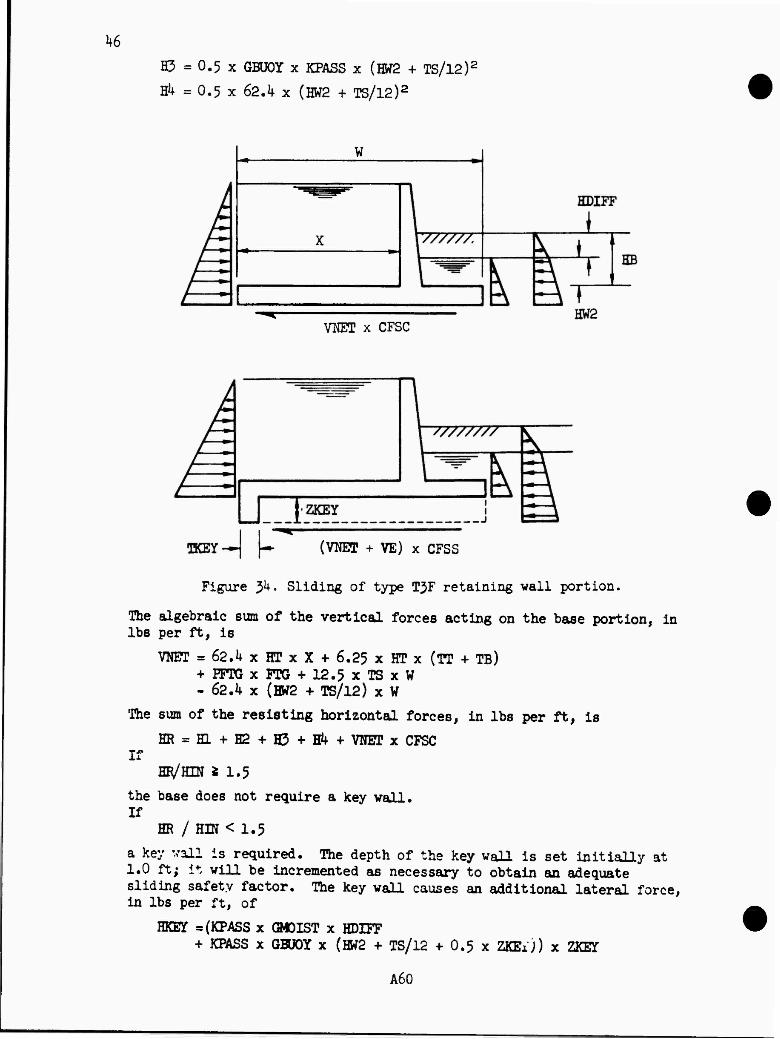
k6 H3 = 0.5 x GBUOY x KPASS x (HW2 + TS/l2)2
Eh = 0.5 x 62.if x (HW2 + TS/l2)2
W
VNET x CFSC
(VNET + VE) x CFSS
Figure 3U. Sliding of type TJF retaining wall portion.
The algebraic sum of the vertical forces acting on the base portion, in lbs per ft, is
VNET ■ 62.4 x HT x X + 6.25 x HT x (TT + TB) + EFTG x FTG + 12.5 x TS x W - 62.k x (EW2 + TS/12) x W
The sum of the resisting horizontal forces, in lbs per ft, is
HR = H1+H2+H3+Hk+ VNET x CFSC If
HR/HIN * 1.5 the base does not require a key wall. If
HR / HIN < 1.5
a key wall is required. The depth of the key wall is set initially at 1.0 ft; it will be incremented as necessary to obtain an adequate sliding safety factor. The key wall causes an additional lateral force, in lbs per ft, of
HKEY =(KPASS x GMOIST x HDE?T + KEASS x GBUOY x (HW2 + TS/12 + 0.5 x ZKEij) x ZKET
A60
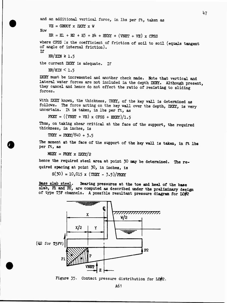
^7 and an additional vertical force, in lbs per ft, taken as
VE = GBOOY x ZKEY x W Now
HR = KL+H2+H3+H4+ HKEY* + (VNET + VE) x CFSS
where CFSS Is the coefficient of friction of soil to soil (equals tangent of angle of internal friction). If
HR/HIN £ 1.5
the current ZKET is adequate. If
HR/HIN < 1.5
ZKEY must be incremented and another check made. Note that vertical and lateral water forces are not included in the depth ZKET. Although present, they cancel and hence do not effect the ratio of resisting to sliding forces•
With ZKET known, the thickness, TKET, of the key wall is determined as follows. The force acting on the key wall over the depth, ZKET, is very uncertain. It is taken, in lbs per ft, as
FKET = ((VNET + VE) x CFSS + HKEY)/l.5
Thus, on taking shear critical at the face of the support, the required thickness, in inches, is
TKET = FKET/840 + 3.5
The moment at the face of the support of the key wall is taken, in ft lbs per ft, as
MKET - FKE3T x ZKET/2
hence the required steel area at point 30 may be determined. The re-
quired spacing at point 30, in inches, is
S(30) = 10,015 x (TKET - 3.5)/FKET
Base slab steel. Bearing pressures at the toe and heel of the base slab, H. and P2, are computed as described under the preliminary design of type T3F channels. A possible resultant pressure diagram for LC#2
(02 for T3FV)
Figure 35. Contact pressure distribution for LC#2.
A61
kB
is shown in Figure 35« Shear, moment, and direct force are computed at the various selected sections. For example at X/2 in the toe for L0#2
P = (VTJET/W)(1 + 12 x E x Y/(W X W))
then the components of shear, in lbs per ft, are
VI = 0.5 x PI x (X/2)
V2 = 0.5 x P x (X/2)
V3 ■ (-62.4 xHT- 12.5 x TS + 62.4 x (HW2 + TS/l2)) x (X/2)
so the total shear on the section is
VS m VI + V2 + V3. The moment on the section, in ft lbs per ft, is
MS = VI x (2/5) x (X/2) + V2 x (1/3) x (X/2) + V3 x (X/2)
Components of the direct force, in lbs per ft, are
HL = 0.5 x GMOIST x K02 x (HDIFF)2
H2 = (MOIST x KD2 x HDIFF x (HW2 + TS/l2)
H5 = 0.5 x GBÜOY x KD2 x (HW2 + TS/12)2
H4 = 0.5 x 62.4 x (BW2 + TS/12)2
H5 = 0.5 x 62.4 x (HT)2
If a key wall is used, the direct force on the section for LC#2 is taken as
NS=HL+H2+R3+H4-H5
When the load condition is LC#1 or if there is no key wall, the frictional force is assumed uniformly distributed along the base. Hence the direct force, with no key wall, is
NS = (X/2)(HL + H2 + S3 + H4 - H5)/W
If the moment, MS, is positive the steel area and spacing pertain to the steel at the bottom of the slab at this section. If MS is negative, the steel area and spacing pertain to the steel at the top. The base thick- ness, TS, is incremented if necessary and the detail design of the retain- ing wall portion of the channel is begun again.
favement slab steel. Bivement slab steel is governed by requirements for temperature and shrinkage or by direct compressive force. For LC#1 the direct compressive force in the pavement slab is taken as the maximum direct compressive force in the toe of the retaining wall base. It is assumed transferred to the pavement slab by bearing. For LC#2, the direct compressive force has two components. One is due to the water in the channel which causes pressure on the ends of the pavement slab. This force, in lbs per ft, is taken conservatively as
NSHT = 62.4 x (HT + TP/24)(TP/l2)
The other component is zero if the direct force in the retaining wall base toe is tension, otherwise the component is taken as the maximum direct compression force in the toe of the base.
A62
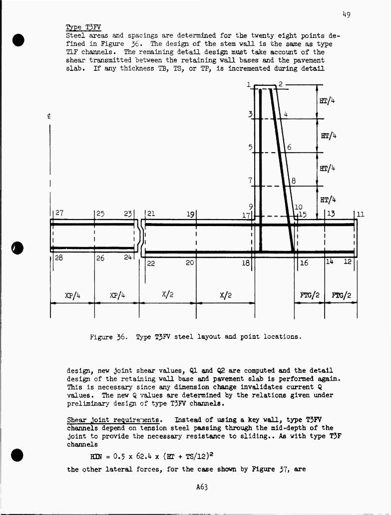
k9 Type T3FV Steel areas and spacings are determined for the twenty eight points de- fined in Figure %. The design of the stem wall is the same as type TIF channels. The remaining detail design must take account of the shear transmitted between the retaining wall bases and the pavement slab. If any thickness TB, TS, or TP, is incremented during detail
•
Figure 36. Type T3FV steel layout and point locations.
design, new joint shear values, Ql and Q2 are computed and the detail design of the retaining wall base and pavement slab is performed again. This is necessary since any dimension change invalidates current Q values. The new Q values are determined by the relations given under preliminary design of type T3FV channels.
Shear joint requirements. Instead of using a key wall, type T3FV channels depend on tension steel passing through the mid-depth of the joint to provide the necessary resistance to sliding.. As with type T3F channels
KEN = 0.5 x 62.4 x (EP + TS/12)2
the other lateral forces, for the case shown by Figure 37, are
A63
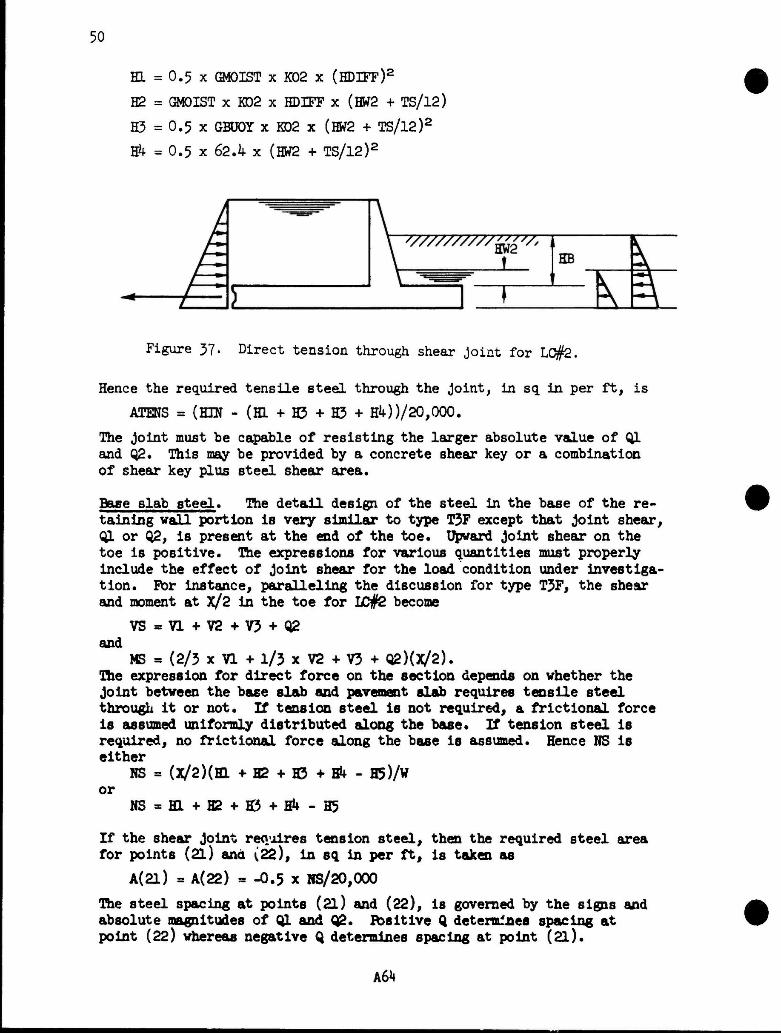
50
HL = 0.5 x ©40IST x K02 x (HDIFF)2
H2 = GMOIST x KD2 x HDIFF x (HVT2 + TS/l2)
H3 = 0.5 x GBÜÖY x KD2 x (HW2 + TS/l2)2
Ek = 0.5 x 62.4 x (HW2 + TS/l2)2
Figure 37. Direct tension through shear joint for LC#2.
Hence the required tensile steel through the joint, in sq. in per ft, is
ATENS = (EOf - (HL + H5 + H3 + HM)/20,000.
The joint must be capable of resisting the larger absolute value of Ql and 02* This may be provided by a concrete shear key or a combination of shear key plus steel shear area.
Base slab steel« The detail design of the steel in the base of the re- taining vail portion is very similar to type T3F except that joint shear, Ql or Q2, is present at the end of the toe. Upward Joint shear on the toe is positive. The expressions for various quantities must properly include the effect of joint shear for the load condition under investiga- tion. For instance, paralleling the discussion for type T3F, the shear and moment at X/2 in the toe for I£#2 become
VS=Vl+V2+V3+02 and
MS = (2/3 xVl+l/3xV2+V3+ Q2)(x/2). The expression for direct force on the section depends on whether the Joint between the base slab and pavement slab requires tensile steel through it or not. If tension steel is not required, a frictional force is assumed uniformly distributed along the base. If tension steel Is required, no frictional force along the base is assumed. Hence NS is either
NS = (X/2)(H1 + H2 + H3 + A - H5)/W or
NS*H1+H2 + Hi5+Hk-H5
If the shear Joint requires tension steel, then the required steel area for points (2l) and {22), in sq in per ft, is taken as
A(2l) = A(22) = -O.5 x RS/20,000
The steel spacing at points (2l) and (22), is governed by the signs and absolute magnitudes of 01 and 02. Ibsitive 0 determines spacing at point (22) whereas negative 0 determines spacing at point (2l).
A64
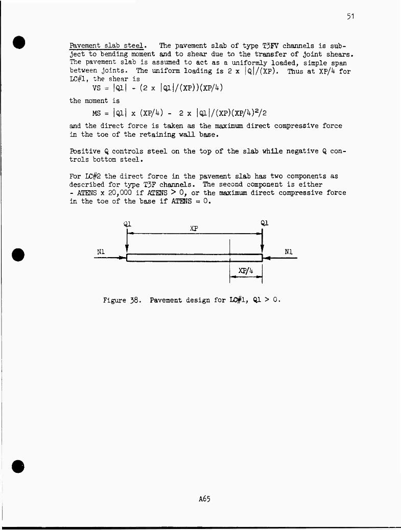
51
Pavement slab steel« The pavement slab of type T3FVr channels is sub- ject to bending moment and to shear due to the transfer of joint shears. The pavement slab is assumed to act as a uniformly loaded, simple span between joints. The uniform loading is 2 x |Q|/(XP). Thus at XP/4 for LC#1, the shear is
vs = |Qx| - (2 x |QI|/(XP))(XPA) the moment is
MS = |Ql| x (XP/4) - 2 x |Ql|/(XP)(XPA)2/2
and the direct force is taken as the maximum direct compressive force in the toe of the retaining wall base.
Positive Q controls steel on the top of the slab while negative Q con- trols bottom steel.
For LC#2 the direct force in the pavement slab has two components as described for type T3F channels. The second component is either - ATENS x 20,000 if ATMS > 0, or the maximum direct compressive force in the toe of the base if ATENS = 0.
01
HI
XP Ql
1 Nl
XPA
Figure 38. Pavement design for L0#1, Ql > 0.
A65
53
Type T1S Steel areas and spacings are determined for the twenty two points, on the wall and floor slab, defined in Figure 39. Steel areas and re- quired perimeters are also determined for the eight points, on the edge beam, defined in Figure kQ. Tension and/or compression steel required
1 ~" "w I
* HC/1+
H
3 i \y 4
t 1 1
BC/ i 5_
ll6 II
ii
7 1 Ö HC/i +
1 \ 1
21
1
19 9
171.
1
_ L .10 Lj.15
1
HC/4
13 1
1 ■ 1
22 20
1
18
1
16
1
Ik !
B/k B/k FTC/2 FTG/2
11
12
Figure 39. Type T1S steel layout and point locations.
in the struts is determined during preliminary design.
Wall and floor slab steel requirements are determined at five cross sections along the longitudinal span between transverse channel joints. These five sections are (l) the sections immediately adjacent to the transverse channel joints, (2) the sections at the struts, and (3) the section mid way between the struts. Rather than list all five (three because of symmetry) sets of steel requirements, one composite set is reported. Inis set consists of the maximum required area and minimum allowable spacing corresponding to each of the twenty two points in the composite section.
Whenever, in the process of detail design, it is necessary to increment either TB, TS, or ET, new edge beam loads are computed, new struts are designed, and the detail design is begun again. Tais is necessary since any dimension change alters existing spans, loads, and relative stiff- nesses, all of which affect edge beam loading.
A67
5*
t C/k c ;A
8 6
C/8 C/8 2 i*
: : T
I? 5 ~
SB
1
ET
Figure kO. Plan of edge beam, steel layout and point location.
Wall steel» Design of wall steel at any one of the cross sections iistea above is essentially the same as the design of type TIF walls except that the support provided the wall by the edge beam, at the particular cross section being investigated, is included in the compu- tations for shear and moment. The direct compression force includes the weights of the struts and edge beam as well as the wall.
As previously noted, the sense of the edge beam loading may be either positive or negative for either LC#1 or LC#2. Thus the sense of the moment at any distance, Z, below the top of the wall is unpredictable. Moment expressions are therefore written such that positive moment in» dicates steel required at an even numbered point in the wall while negative moment indicates steel at an odd numbered point. Thus if both LC#1 and LC#2 produced negative moments at a particular Z value, the largest area and smallest spacing would be tabulated for the corresponding odd numbered point.
floor slab steel. The design of floor slab steel at any cross-section is essentially the same as the design of type TIF floor slabs* It is only necessary to modify the expressions for Mf, NW, and HWALL, see page 1*2, to include the effects of edge beam loadings and weights. Assume a positive edge beam loading, BXL, in lbs per ft, is added to Figure Jl. lfcen the term -HJDL x (HP - JSB/2k + TS/2U) is added to the expression for W and the term -RX1 is added to the expression for HWALL. The value of KJGL is that at the particular cross section under investigation. The term 150(BT - TT) x EB/lkk plus a term accounting for strut weight is added to the expression for NW. With these changes, the analysis proceeds as described for type TIF channel floor slabs.
Edge beam steel. A summation process is used to obtain the shears and moments at the one-eighth points of the edge beam span. Either load condition can produce moments of either sense at any section of the span. Hence an approach similar to that indicated for the vail steel is used here to determine critical steel requirements at the odd and even numbered points shown in Figure kO.
A68
55
Figure kl. Edge beam loading for LC#1 when RX1 > 0.
The procedure used to obtain required steel area is based on a moment per foot of width« Hence, if the moment at a section of the edge beam is M ft lbs. the equivalent moment per foot of width is
ME = H^(EB/12)
from which the required area per foot of width is obtained, if this is AE, the total required area at the section. In sq« inches, is
A m AEx (KB/12).
FLexural bond requirements are satisfied by determining the steel peri- meter required at the eight edge beam points. For any shear. V, in lbs. the required perimeter. So, In inches, is taken as
Eo JL V V uJD * 3V7 x 7/8 x D s 303.6 x D
The allowable bond stress for #7 bars is used« Thus the computed perl- meter Is conservative for all bars of equal or smaller diameter than #7.
Edge beam stirrups. When edge beam web steel is required for diagonal tension, the maximum shear stress is not allowed to exceed 3*JP « 190 pel. EB may need to be incremented, and ET recomputed, to hold the shear stress to this limit. Maximum allowable spacing of the web steel is then the smallest of:
D/2
AV/(0.0015 x EB)
20000 x AV x D/VRP
S
s s
in which
VHP «V-70xEBxD
ACI 1206(a)
ACI 1206(b)
ACI 1203
A69
56
where V = shear at section under investigation, in lbs per ft
VPR = shear carried by web steel, in lbs per ft
D = effective depth, in inches
AV = area of web steel, twice the bar area, in sq inches
S = maximum allowable web steel spacing, in inches
AV is initially set at 0.22 sq in for #3 stirrups. If S, for this area, is less than k inches, the stirrup size is increased to #4, the spacing is recomputed, etc. Although the maximum allowable spacing may be com- puted at either sections D distance from the faces of the supports or the section at the centerline of the support, the spacing is conserva- tively reported as that at D from the faces.
The web steel layout may be selected by consideration of a diagram similar to that of Figure 42. The ordinates of the diagram are re- quired values of AV/s. They may be assumed to vary linearly from zero to a maximum over the supports. The ordinate at D from the faces of the strut is obtained from the required stirrup size and spacing com- puted above.
vary size and spacing as desired
computed size and spacing
vary size and spacing as desired
Figure k2. Layout of edge beam stirrups.
A70
57 Computer Designs
Input From one to four lines of input data are required for each design run. A given computer job may include many design runs. A design run is made for a particular set of design conditions and takes one of two forms. The first form consists of four preliminary designs, one for each channel type, plus an indication of the channel type that might be selected for detail design on the basis of least concrete volume. The second form consists of the detail design of one of the four chan- nel types.
Tne input data provided per design run consists essentially of values for the primary design parameters and, if desired, values for the second- ary design parameters. Table 2 shows the lines that may be provided per run together with the specific parameters contained on the four lines.
Table 2. Input values per design run
B HT HB DESIGN DEFAULT 1 DEFAULT 2 DEFAULT I HW1 HW2 HWP GMOIST GSAT KOI K02 FLOATR MAXFTG JOINTS MFOUND CFSC CFSS KPASS
The first line contains the primary parameters B, HT, and HB and is always required. If DESIGN = 0, the four preliminary designs are per- formed. If DESIGN = 1, 2, 3, or k, then the detail design of type TIF, T3F, T3FV, or T1S is performed, (if desired, the Design Unit can run the detail design of the structural channel type indicated from the pre- liminary designs. However, it will often be a better procedure if the concerned designer will take a critical look at the preliminary design results before a detail design is run.)
If DEFAULT 1 > 0, the next line of input data must be provided, it con- tains values for HW1 through FLOATR as indicated. If DEFAULT 1=0, this line of input data must not be included, default values for the eight parameters will be provided by the computer.
If DEFAULT 2 > 0, the next line containing values for MAXFTG, JOINTS, and MFOUND must be provided. If DEFAULT 2 •= 0, default values will be used and the line must be omitted, similarly for DEFAULT 3 and the line containing CFSC, CFSS, and KPASS.
Thus the number of lines of data that must be provided per design run will vary depending on whether the default values are satisfactory or whether the user wishes to supply some or all of the secondary parameter values. Note that although various lines may be omitted, those supplied must be complete and in the order indicated.
Output The output for each design run, whether preliminary designs or a detail design, gives the parameter values assumed for that run. These para- meters are listed and identified at the beginning of the design.
Revised 7/77
A71
58
Preliminary designs. Preliminary design results are listed in the order TIF, T3F, T3FV, and T1S, see Figure 1*3 • Output values consist of distances, thicknesses, and concrete volumes in cubic yards per longitudinal foot of channel. The thicknesses and distances, in inches and feet, may be identified by reference to various figures:
for type TIF see Figures 5 and 6 for type T3F see Figures 5> 1> and 9 for type T3FV see Figures 5, 7, and 9 for type T1S see Figure 13.
Detail Designs. The output for the detail design of any channel type includes three segments: a repeat cf .he preliminary design results, a similar output giving final dimensions (this will often be identical to the preliminary design values), and a listing of steel requirements giving required area and maximum allowable spacing in sq. in. per ft and inches.
■type TIF. - See Figures hk and 4$ for output examples, see Figure 29 for the steel locations listed.
Ttype T3F. - See Figures MS and kj for output examples, see Figure 33 for the steel locations listed. Note that a key wall is required in Figure ^7, the required depth of the wall is given in ft and the re- quired thickness of the wall is given in inches.
Type T3FV. - See Figures UÖ and k9 for output examples, see Figure 36 for the steel locations listed. Rote that the shear forces transmitted across the shear Joint are given In lbs per ft for LC#1 and LC#2. Hie tension steel area, In sq Inches per ft, through the joint is also given.
Type T1S. - See Figures 50 and 51 for output examples, see Figures 39 and UO for wall and edge beam steel locations* Required strut steel areas, in sq Inches, are given for tension and compression. Required edge beam web steel is given by bar site and spacing in inches. Required edge beam longitudinal steel areas, in sq inches, and perimeters, in inches, are given for eight locations.
A72
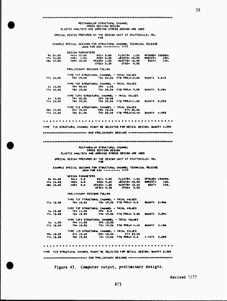
59
RECTANGULAR STRUCTURAL CHANNEL CROSS SECTION DCStON
CLASTIC ANALYSIS AMD WORKING STRESS DESIGN ARC USCO
SPECIAL OESIGN PRCPARCD OY THE DESIGN UN|T AT HVATTSVlLLEt NO. FOR
EXAMPLE 5PECUL DESIGNS FO» STRUCTURAL CHANNEL TECHNICAL RELEASE JOAN FOR ESA -»-——— T/7T
OES1GN PARAMETERS P.* 24.00 M«|« 12.00 KOI« 0.00 FLOATRa 1.50 NFOUNOa 100900.
Him 14.00 *»?» I.SO K02« 0.20 JOINTS« 40.00 GNOlSTa 120. MB« IS.00 MMP« 12.00 KPASS« 1.25 MAKFTO« 12.00 OSAT« MO«
CFSCa 0.3S CFSS« O.SS
PRELIMINARY DESIGNS FOLLO«
TYPE TIF STRUCTURAL CHANNEL - TRIAL VALUES TT. 10.00 TM It.00 TS« 24.00 FT« PROJ».0.GO OUANT« S.01S
TYPE T3F STRUCTURAL CHANNEL - TKfAL VALUES la 10.00 TPa 90.00 XPa 4.00
TT. 10.00 Tta 19.00 TS« 20.00 FT« PROJ« 9.GO OUANTa 5.06*
TYPE TJFV STRUCTURAL CHANNEL - TPIAL VALUES Xa 3.00 TPa 32.00 XPa It.00
TTm 10.00 Tta 19.00 TS« 20.00 FT« PPOJ-U.AO OUANTa S.20G
TYPE T1S STRUCTURAL CHANNEL - TRIAL VALUES S»a 12.00 STa 15.00 El« IS.00 ET« 24.00 TTa 10.00 Tta 21.00 TSa 22.00 FTt PROJ*10.40 OUANTa 4.990
TYPE T1S STRUCTURAL CHANNEL "IGHT IE SELECTED FOR DETAIL OE$l*N. OUANT« «.990
aaaa.aaaaaaaaaaaaaaaaaaaaa« fNO PRCLlNtNARV OCSIUNS •••»»■»•»»#«*••••••*■•»«•»•
RECTANGULAR STRUCTURAL CHANNEL CROSS SECTION DESIGN
ELASTIC ANALYSIS ANO »OG*tN* STRESS OfSION ARC USED
SPECIAL DESIGN PREPARCO RV THf DESIGN UNIT AT HVATTSVlLLft MO. roR
EXAMPLE SPECIAL DESIGNS FOR STRUCTURAL CHANNEL TECHNICAL RELEASE JOAN FOR ESA ———— T/TT
OCS1GN PAGANCTCRS Ga 2*.00 H«I« 0.0 «01+ O.GO FLt**TR» 1.S0 MFOUJIO* tOOOGG.
•*!« 14.00 HV2» 0.0 ROt« 0.20 JOINTS« «0,00 G»OtST» MO. Hta 15*00 HMP» 0.0 «PASS« 1.2S M«XFTO« U.«0 GtAT« 14«.
c#sc» «.is crss« o.ss
PRELIMINARY DESIGNS FOLLO»
TYPE TIF «TRUCTURAL CHANNEL • TRfAL VALUES TT« 10.00 TRa 10.t» TS« 19.00 FTO) PROJ* 0.0 OUANTa f»9GG
TYPE TSF STRUCTURAL CHANNEL - TRIAL VALUES X« 12.00 TPa 11.00 XPa 0.0
TTa 10.00 Tf» 14.00 TS« 19.00 FT« PROJ* 2,00 OUANTa 1.29*
TYPE TJFV STRUCTURAL CHANNEL * TRIAL VALUES la 4.00 TP« 11.00 iPa 12.00
TT« 10.09 T*a )G.0G TS» 19.00 FTO PROJ* ».40 OUANTa Kit»
TYPE IIS STRUCTURAL CHANNEL - TRIAL VALUES «Ra 12.00 ST« 15.90 ER» IS.00 ET« 29.00 TTa 10.00 T9» 12.00 V*a 13.09 FTO *«Oj* 0.0 fiJANt» t.*0»
TTPC TIS STRUCTURAL CHANNtL N|tNT RC ULECTEO FOR DETAIL GESIG«. OUANT» i.i*%
,li.i,»M*MMii iu> CMC PRELIMINARY Of SIGNS «••««««•«•«•aaaaaaaaaa*»»»«
Figure 43. Computer output, preliainmry designs.
Revised 7/7?
A?3
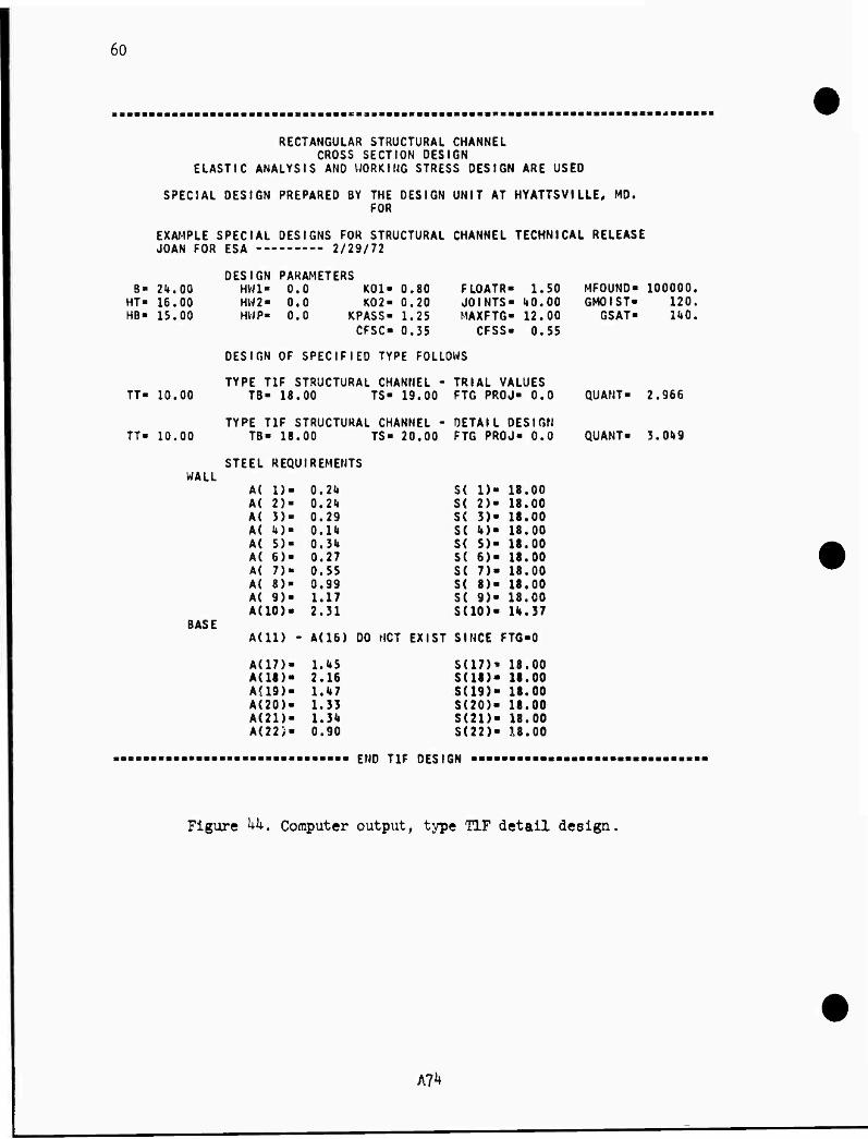
60
RECTANGULAR STRUCTURAL CHANNEL CROSS SECTION DESIGN
ELASTIC ANALYSIS ANO WORKING STRESS DESIGN ARE USED
SPECIAL DESIGN PREPARED BY THE DESIGN UNIT AT HYATTSVILLE, MD. FOR
EXAMPLE SPECIAL DESIGNS FOR STRUCTURAL CHANNEL TECHNICAL RELEASE JOAN FOR ESA — 2/29/72
DESIGN PARAMETERS B- 21». 00 HW1- 0.0 KOI« 0.80
HT- 16.00 HW2- 0.0 K02- 0.20 HB- 15.00 HWP- 0.0 KPASS« 1.25
CFSC- 0.35
FLOATR- 1.50 MFOUND- 100000. JOINTS- U0.00 GMOIST- 120. MAXFTG- 12.00 GSAT- no.
CFSS- 0.55
TT- 10.00
DESIGN OF SPECIFIED TYPE FOLLOWS
TYPE TIF STRUCTURAL CHANNEL - TRIAL VALUES TB- 18.00 TS- 19.00 FTG PROJ- 0.0 QUANT- 2.966
TYPE TIF STRUCTURAL CHANNEL - DETAIL DESIGN TT- 10.00 TB- 18.00 TS- 20.00 FTG PROJ- 0.0 QUANT- 3.01» 9
WALL STEEL REQUIREMENTS
BASE
A( 1)- A( 2)« A< 3)- A( U)- A( 5)- A( 6)- A( 7)- A{ 8)- A( 9)- A(10>-
0.24 0.21» 0.29 0.1«* 0.3U 0.27 0.55 0.99 1.17 2.31
S( D- 18.00 S( 2)- 18.00 S( 3)- 18.00 S( U)« S< 5)« S( 6)« S( 7)- S( 8)- 18.00 S( 9)- 18.00 S(10)- 11».37
18.00 18.00 18.00 18.00
A(U) - A(16) DO MOT EXIST SINCE FTG-0
A(17)- A(18)« AH9). A(20). A(21)> A(22>«
1.U5 2.16 l.l»7 1.33 1.3<» 0.90
S(17)i 5(18)« S(19)> S(20)< S(2D- S(22)<
18.00 18.00 18.00 18.00 18.00 18.00
END TIF DESIGN
Figure kk. Computer output, type TIF detail design.
tfk
61
s:::ts:s::s:s = ::=s:s:::::s::ss3s33:3S2SS3Sssts:s:szz»si3SSS»itBHMts:ssss::t
RECTANGULAR STRUCTURAL CHANNEL CROSS SECTION OESIGN
ELASTIC ANALYSIS ANO WORKING STRESS DESIGN ARE USED
SPECIAL OESIGN PREPARED BY THE DESI3N UNIT AT HYATTSVlLLEt HD. FOR
EXAMPLE SPECIAL DESIGNS FOR STRUCTURAL CHANNEL TECHNICAL RELEASE JOAN FOR ESA 7/77
DESIGN PA».PETERS R = 24.00 H«l« 13.00 KOI« 0.80
HTr 16.00 HW? = 1.50 K02 = 0.20 HRs IS.00 H*P = 12.00 KPASS« 1.25
CFSC« 0.35
FLOATR* 1.50 JOINTS« 40.00 MAXFTG« 12.00
CFSS« 0.55
MFOUND* 100000. GHOISTs 120.
GSAT« 140.
TT =
TT =
OESIGN OF SPECIFIED TYPE FOLLOWS
TYPE TIF STRUCTURAL CHANNEL - TRIAL VALUES 10.00 TR= 19.00 TS* 24.00 FTG PROJ»10.60
TYPE TIF STRUCTURAL CHANNEL - OETAIL DESIGN 10.00 TfU 19.00 TS» 24.00 FTG PROJ«10.60
QUANT« 5.015
QUANT« 5.015
STEEL REQUIREMENTS WALL
BASE
A( 1) = 0.24 A< 2)» 0.24 A( 3)« 0.29 A( 4)« 0.15 A( 5)« 0.35 A< 6)« 0.27 A( 7)« 0.52 A( 8>« 1.05 A( 9)« 1.08 A(10>« 2.50
»111)« 0.29 A(12)> 0*29 AU3)" 0„29 A<14)> 0.29 A(15)« 0.84 A(16)« 0.40
A(17)« 0.72 A(18)« 0.39 A(19)« 0.82 A(20>« 0.29 A<21)* 0.80 A(22)« 0.29
S( 1» S< 2) S( 3) S( 4) S( 5) S( 6) S( 7) S( 8) S( 9) S(10)
S(ll) S(12) SU3) S(14) SU5» S(16)
S(17) SI18) 5U9) S(20) Si?\) S(22)
18.00 18.00 18.00 18.00 18.00 18.00 18.00 18.00 18.00 12.86
18.00 18.00 18.00 18.00 18.00 18.00
18.00 18.00 18.00 18.00 18.00 18.00
mitiiistiiistiiatiisiiiiiiiiii END TiF DESIGN
Figure 45. Computer output, type TIF detail design.
Revised 7/7!
A75
62
RECTANGULAR STRUCTURAL CHANNEL CROSS SECTION DESIGN
ELASTIC ANALYSIS AND WORKING STRESS DESIGN ARE USED
SPECIAL DESIGN PREPARED BY THE DESIGN UNIT AT HYATTSVILLE, MD. FOR
EXAMPLE SPECIAL DESIGNS FOR STRUCTURAL CHANNEL TECHNICAL RELEASE WUAN r u K CdA « Lfl^lll
DESIGN PARAMETERS B- 21». 00 HW1- 0.0 KOI- 0.80 FLOATR- 1.50 MFOUND- 100000.
HT- 16.00 HW2- 0.0 K02« 0.20 JOINTS- 40.00 GMOIST- 120. HB- 4.00 HWP« 0.0 KPASS- 1.25 MAXFTG- 12.00 GSAT- 140.
CFSC- 0.35 CFSS- 0.55
DESIGN OF SPECIFIED TYPE FOLLOWS
TYPE T3F STRUCTURAL CHANNEL - TRIAL VALUES X- 10.00 TP- 11.00 XP- 4.00 TT« 10.00 TB- 16.00 TS- 17.00 FTG PROJ- 4.60
TYPE T3F STRUCTURAL CHANNEL - DETAIL DESIGN X- 10.00 TP- 11.00 XP- 4.00
TT- 10.00 TB« 16.00 TS- 17.00 FTG PROJ- 4.60
WALL STEEL REQUIREMENTS
A( 1). • 0.24 A( 2)* • 0.24 A( 3)« * 0.28 A( 4). ■ 0.28 A( 5)« ■ 0.31 A( G)< » 0.31 A( 7)« ■ 0.94 A( 8)< • 0.35 A( 9)' * 2.08 A(10)< * 0.19
BASE A(ll). ■ 0.20 A(12)< • 0.20 A<13)« * 0.20 A<14>« • 0.20 AUS)' ■ 0.20 A<16>« • 0.65
A(17). • 1.75 AU8)« • 0.20 A(19)> • 0.70 A(20)< • 0.20 A<21>« ■ 0.41 A<22)« ■ 0.20
KEY WALL DEPTH- ■ 2.00 THICK« - 14.00 A<29)' • 0.17 A(30)' • 0.50
PAVEMENT SLAB A(23)' * 0.26 A(24)' ■ 0.13 A<25>« - 0.26 A(26)> • 0.13 A(27>« * 0.25 A(28)- » ü.13
II ii S( 3) S( 4) S( 5) S( 6) S( 7) S( 8) S( 9) $(10)
S(ll) S(12) SC13) S(14) S(15) S(16)
S(17> S(18) S(19) S(20) S(21) S(22)
S(29)< SC30>«
18.00 18.00 18.00 18.00 18.00 18.00 18.00 18.00 17.34 18.00
18.00 18.00 18.00 18.00 18.00 18.00
18.00 18.00 18.00 18.00 18.00 18.00
18.00 12.87
S(23)> S(24)« S(25). S(26). S(27)- 18.00 S(28)- 18.00
18.00 18.00 18.00 18.00
QUANT- 3.092
QUANT- 3.265
EN0 TJp DESIGN - —
Figure 46. Computer output, type T3F detail design.
A76
63
RECTANGULAR STRUCTURAL CHANNEL CROSS SECTION DESIGN
ELASTIC ANALYSIS AND WORKING STRESS DESIGN ARE USED
SPECIAL DESIGN PREPARED BY THE DESIGN UNIT AT HYATTSVILLE, MD. FOR
EXAMPLE SPECIAL DESIGNS FOR STRUCTURAL CHANNEL TECHNICAL RELEASE JOAN FOR ESA - 2/29/72
B- 2U.00 HT- 16.00 HB- 15.00
X« 10.00 TT- 10.00
0.80 FLOATR- 1.50 MFOUND- 100000. 0.20 JOINTS- U0.00 GMOIST- 120. 1.25 MAXFTG- 12.00 GSAT- HO. 0.35 CFSS- 0.55
DESIGN PARAMETERS HW1- 12.00 KOI« HW2- 1.50 K02- HWP- 12.00 KPACS-
CFSC«
DESIGN OF SPECIFIED TYPE FOLLOWS
TYPE T5F STRUCTURAL CHANNEL - TRIAL VALUES TP- 90.00 XP- I».00 TB- 19.00 TS- 20.00 FTG PROJ- 9.00 QUANT- 5.081»
X- TT«
10.00 10.00
WALL
TYPE T3F STRUCTURAL CHANNEL • TP- 90.00 XP- U.00 TB- 19.00 TS- 20.00
STEEL REQUIREMENTS
DETAIL DESIGN
FTG PROJ- 9.00 QUANT- 5.08U
BASE
A( 1)- A( 2>- A( 3)- A( <*)• A( 5)- A( 6>- A( 7>- A( 8)- A( 9)- A(10)-
A(ll)- A(12>- AU3)- Add}" A(15)- A(16)-
A(17)- A<18>- r(X9>- A(20)- A<21>- A(22)-
0.2«* 0.2% 0.29 0.15 0.35 0.27 0.52 1.05 1.08 2.50
0.2U 0.21» 0.28 0.21) 1.31 0.58
0.71 l.%7 O.U 0.27 0.<»8 0.2d
S( 1)' S( 2)*
U l\: S( 5)< S( 6)« S( 7). S( 8)* S( 9)> S(IO)«
S(ll)« SC12)« S<13)< S(U)> S<15>« S(16)«
SU7)« $<18)> S(19)i S(20>« S(21)< S(22)«
KEY WALL NOT REQUIRED
PAVEMENT SLAB A(23)- 0.77 A(2t)- 0.38 A(25>- 0.77 A(26)- 0.38 A(27)- 0.77 A(28)- 0.38
18.00 18.00 18.00 18.00 18.00 18.00 18.00 18.00 18.00 12.86
18.00 18.00 18.00 18.00 16.43 18.00
18.00 18.00 18.00 18.00 18.00 18.00
S(23)- 18.00 S(2«*)- 18.00 S(25) S(26) S(27)
18.00 18.00 18.00
S<28)- 18.00
•
ENO T3F DESIGN
Figure kf. Computer output, type T3F detail design.
A77
6k :::::::::::::::::::::::::::::::: :::::s::r::::s::ss:::s3:st<tt»xtaist
PFCTANGULAR STRUCTURAL CHANNEL CROSS SECTION DESIGN
ELASTIC ANALYSIS AND WORKING STRESS DESIGN ARE USED
SPECIAL DESIGN PREPARED RY THE DESIGN UNIT AT HYATTSVlLLE. MD. FOR
EXAMPLE SPECIAL DESIGNS fOR STRUCTURAL CHANNEL TECHNICAL RELEASE JOAN FOR ESA ——— 7/77
P= 24.00 wT= 1*.Q0 HP = 15.00
X = fc.00 T^= 10.00
Xr *.00 TT= 10.00
DESIGN PARAMETERS MWls 0.0 KOI» O.flO TLOATR* 1.50 HW? = 0.0 K02» 0.20 JOINTS» 40.00 MWP= 0,0 KRASS« 1.25 MAXFTG* 12.00
CFSC» 0.35 CFSS» 0.55
DESIGN OF SPECIFIED TYPE FOLLOWS
TYPE T3FV STRUCTURAL CHANNEL - TRIAL VALUES TP« 11.00 XP« 12.00 Tp= 1-4.00 TS» 19.00 FTG PROJ« 4.40
TYPE T3FV STRUCTURAL CHANNEL - DETAIL DESIGN TP» 11.00 XP* 12.00 To* IM.UO TS« 19.00 FTG PROJ« 4.40
STEEL KEQUIMEMENTS WALL
4< n» 0.24 S( 1)« 10.00 A< 2)» »».24 S( 2>« 18.00 A( 3)« 0.29 S( 3)« 18.00 4( 4)« 0.14 S( 4)» 1A.00 A( b) = 0.34 S( 5)« 18.00 A( bis 0.27 S( 6)« 18.00 A( 7)« 0.55 S( 7)» 18.00 A( 8)* 0.99 S( 8)» 18.00 At 9)» 1.17 SC 9)« 18.00 A(10>« 2.31 SUO)« 14.37
BASF Alii)» 0.23 sun« 18.00 A f12)* 0.21 S(12)« 18.00 A(13)« 0.23 S(13»« 18.00 4(14)* n.23 S(14)« 18.00 A(ib>» n.59 S(15)» 15.98 Aflbl« 0.36 51161« 18.00
4(17)» l.OS 5(171« 18.00 Add)» 1.56 SUSI« 16.39 A(19)« 0.57 S(19)» 18.00 4(20)» 0.40 S(20>» 18.00 M21t« 0.46 S(2i>« 18.00 A(22l« 0.23 S(22»» 18.OG
SMEA* CONNECTION REUD TENSION STEEL AREA« 0.31 SMEAM FüHCE FOR LC NO.l» 4.5867E«03 SMEAR FORCE FOB LC NO.2» -3.0020E»03
PAVEMENT SLAB 4(23)« 0.26 S(23>« 18.00 A(24)> n.13 S(24)« 10.00 4(35)« 0.42 S(2*>« 18.00 4(26)« n.78 S(26)« 18.00 4(27)B 0.71 S(27)« 18.00 A(2H)« 0.99 S(?8)« 18.00
MFOUND» 100000. GMOIST» 120.
GSAT» 140.
QUANT» 3.186
QUANT» 3.186
ittititttitixiiinttiiiiiiiitt fsO T3FV OESIGN
Figure 48. Computer output, type T3FV detail design.
Revised 7/77
A78
65
RECTANGULAR STRUCTURAL CHANNEL CROSS SECTION DESI6N
ELASTIC ANALYSIS ANO WORKING STRESS DESIGN ARE USEO
SPECIAL DESIGN PREPARED BY THE DESIGN UNIT AT HYATTSVILLEt MO. FOR
EXAMPLE SPECIAL DESIGNS FOR STRUCTURAL CHANNEL TECHNICAL RELEASE JOAN FOR ESA 7/77
DESIGN PARAMETERS B« 24.00 MWl« 12.00 KOI« 0.80
HT* 16.00 HW2» 1.50 K02« 0.20 HB« 15.00 HWP« 12.00 KPASS« 1.25
CFSC« 0.35
FLOATR« 1.50 JOINTS« 40.00 MAXFTG« 12.00
CFSS« 0.55
MFOUND* 100000. GMOIST« 120.
GSAT« 140.
DESIGN OF SPECIFIED TYPE FOLLOWS
TYPE T3FV STRUCTURAL CHANNEL - TRIAL VALUES X« 3.00 TP« 32.00 XP« 18.00
TT« 10.00 TR« 19.00 TS« 20.00 FTG PROJM1.60
TYPE T3FV STRUCTURAL CHANNEL - OETAIL DESIGN X» 3.00 TP« 32.00 XP* 18.00
TT« 10.00 TR« 19.00 TS« 20.00 FTG PR0J«11.60
QUANT« 5.208
QUANT» 5.208
STEEL REQUIREMENTS WALL
8ASE
A( n« A( 2)« A( 3)« A( 4)« A( 5)« A( 6)> A( 7)« A( 8)« At 9)« A(10>«
At III" A(12J« A<13>« A(14)« AU5)« A<16>«
Af171« AU8>« AU9)« A<20>« AJ21I« A(22)»
0.24 0.24 0.29 0.15 0.35 0.27 0.52 1.05 1.08 2.50
0.24 0.24 0.32 0.40 1.74 1.14
0*48 0.53 0.48 0.24 0.48 0.24
SHEAR CONNECTION «COO TENSION STEEL AREA* SHCAR FORCE FOR LC NO.II SHEAR FORCE FOR LC NO.2«
PAVEMENT SLAB A(23)« 0.77 AI24)« 0.38 A«2$)« 0.77 A(2*>« 0.38 At27>« 0.77 A(28l« 0.38
st n« 18.00 S( 2)» 18.00 S< 3)« 18.00 S( 4)« 18.00 S( 5)» 18.00 S( 6)« 18.00 S! 7>« 18.00 S( 8)* 18.00 S< 9>« 18.00 SU0>« 12.88
sun« 18.00 SU2>» 18.00 S(13>« 18.00 S(14>* 18.00 S<15>« 14.25 SU6>* 18.00
SU7)» 18.00 S(1R>* 16.85 sun« 18.00 SI20)« 18.00 SI2D» 18.00 SC22)« 18.00
8.31 6.5370E»03 S.7764E*03
SC23J« 18.00 SI24)« 18.00 S(25>» 18.00 S<2*>" 18.00 SI27I« 18.00 S(28)« 18.00
END T3FV UESIGN
Figure 49. Computer output, type T3FV detail design.
Revised 7/77
A79
66
RECTANGULAR STRUCTURAL CHANNEL CROSS SECTION OESIGN
ELASTIC ANALYSIS AND WORKING STRESS DESIGN ARE USED
SPECIAL DESIGN PREPARED BY THE DESIGN UNIT AT HYATTSVILLE, MO. FOR
EXAMPLE SPECIAL DESIGNS FOR STRUCTURAL CHANNEL TECHNICAL RELEASE JUAN ru K taA --------- i/i)ii 11
DESIGN PARAMETERS B- 2(1.00 M/l- 0.0 KOI- 0.80 FLOATR- 1.50
HT- 16.00 HU2- 0.0 K02- 0.20 JOINTS- U0.00 HB- 15.00 HWP« 0.0 KPASS» 1.25 MAXFTG- 12.00
CFSC- 0.35 CFSS- 0.55
MFOUND- 100000. GMOIST- 120.
GSAT- HO.
DESIGN OF SPECIFIED TYPE FOLLOWS
TYPE T1S STRUCTURAL CHANNEL - TRIAL VALUES SB- 12.00 ST- 15.00 EB- 15.00 ET- 25.00 TT- 10.00 TB- 12.00 TS- 13.00 FTG PROJ- 0.0
TYPE T1S STRUCTURAL CHANNEL - DETAIL DESIGN SB- 12.00 ST- 15.00 EB- 15.00 ET- 23.00 TT- 10.00 TB- 12.00 TS- 13.00 FTG PROJ- 0.0
STEEL REQUIREMENTS WALL
A( D- 0.2% S( D- 18.00 A( 2>- 0.12 S( 2)- 18.00 A( 3>- 0.86 SC 3)- 18.00 A( %)■ 0.67 S( %)• 18.00 A( 5>- 1.11 SC 5)- 18.00 A( 6)- 0.95 S< 6)- 18.00 A( 7>- 0.56 S( 7)- 18.00 A( 8)- 0.8* S( 8)- 18.00 A( 9>- 0.29 S( 9)- 18.00 AC10)- 1.0% S(10)- 11.%6
BASE A(ll) - A(16) DO NOT EXIS1 ' SINCE FTG-0
AC17>- 0.31 S(17)- 18.00 A(18). 1.0% S(18)- 18.00 AC19>- 0.%2 S(19)- 18.00 AC20>- 0.16 S(20)- 18.00 AC2D- 0.39 S(2D- 18.00 AC22>- 0.16 S(22)- 18.00
STRUT STEEL REQO TENSION STEEL AREA • 2.15 REQO COMPRES STEEL AREA • 2.15
EDGE BEAM STEEL STIRRUPS REQUIRED. USE AT LEAST
NO. 3 AT 9.7 IN. CC AT D DISTANCES FROM FACES OF
A( D- 0.85 A( 2)- 1.02 AC 3)- 3.6% AC %)• %.%! AC 5)- 0.72 AC 6)- 0.86 AC 7)- 3.5% AC 8)- 2.77
TRUTS 1 2 3 % I 2 0 0
.75
.10
.SC
.26
.86
.23
.0
.0
QUANT- 2.285
QUANT- 2.285
END T1S DESIGN
Figure 50. Computer output, type IIS detail design.
A80
67
RECTANGULAR STRUCTURAL CHANNEL CROSS SECTION DESIGN
ELASTIC ANALYSIS AND WORKING STRESS OESIGN ARE USED
SPECIAL DESIGN PREPARED BY THE DESIGN UNIT AT HYATTSVILLE, MD. FOR
EXAMPLE SPECIAL DESIGNS FOR STRUCTURAL CHANNEL TECHNICAL RELEASE JUAN ru K CiM --------- ifl^lll
DESIGN PARAMETERS B- 21».00 MW1- 12.OG KOI« 0.80 FLOATR- 1.50 MFOUND- 100000.
HT- 16.00 HW2- 1.50 K02- 0.20 JOINTS- «0.00 GMOIST- 120. HB- 15.00 HUP- 12.00 KPASS- 1.25
CFSC- 0.55 MAXFTG- 12.00
CFSS- 0.55 GSAT- HO.
SB- TT-
12.00 10.00
DESIGN OF SPECIFIED TYPE FOLLOWS
TYPE T1S STRUCTURAL CHANNEL - TRIAL VALUES ST« 15.00 EB- IS.00 ET- 26.00 TB- 21.00 TS- 22.00 FTG PROJ-10.«O QUANT- l*. 990
TYPE T1S STRUCTURAL CHANNEL - DETAIL DESIGN SB- 12.00 ST- 15.00 EB- 15.00 ET- 26.00 TT- 10.00 TB- 21.00 TS- 22.00 FTG PROJ-10.«0
MALL STEEL REQUIREMENTS
BASE
A( 1) A( 2) A( 3) A( l») A< 5) A( 6) A( 7) A( I) A( 9) AUO)
A(ll) A(12) A(13) A(l%) A(15) A(16)
A(17) A(18) A(19) A(20) A(21) A(22)
0.26 0.17 0.32 0.93 0.38 1.25 O.U 1.55 0.50 2.13
0.26 0.26 0.26 0.26 1.05 0.26
0.53 0.83 0.75 0.26 0.9% 0.26
STRUT STEEL MEQO TENSION STEEL AREA KEQO COMPRES STEEL AREA
S( 1) S( 2) S( 3) S( «) S( 5) S( 6) S( 7) S( 6) S( 9) S(10)
sun S(12) S(13) S(l«) sus> S(16)
S(17) S(18) $(19) S(20) SCI) $(22)
3.70 0.0
18.00 18.00 18.00 18.00 18.00 18.00 18.00 18.00 18.00 13.30
18.00 16.00 18.00 16.00 18.00 18.00
18.00 17.5% 18.00 16.00 18.00 16.00
EDGE BEAM STEEL STIRRUPS REQUIRED, USE AT LEAST
NO. 3 AT 6.6 IN. CC AT D 01 STANCES FROM FACES OF STRUTS
A( 1). A( 2)- A( 3)- A( *)• A( 5)- A( 6)- A( 7). A( 8)-
1.18 0.0 5.2« 0.0 0.72 0.0 0.0 «.71
P( P( P(
2). 3)«
P( %)• P( $)• P( 6)- P( 7)- P( 8)»
2.16 0.0 5.36 0.0 2.83 0.0 0.0 0.0
QUANT- «.990
EM) T1S DESIGN
Figure 51« Computer output, type US detail design.
A81
APPENDIX B: SAMPLE CCHAN RUN FOR PRELIMINARY DESIGNS
CCHAN — SOIL CONSERVATION SERVICE PROGRAM STRUCHAN ADAPTED TO CORPS OF ENGINEERS CRITERIA BY CASE PROJECT ft******************************************************
ft*************************** ♦ CORPS PROGRAM * X0097 * * MICRO VERSION ♦ 89/02/01 * it***************************
ENTER FIRST HEADER LINE Example Special Design -for Structural Channels ENTER SECOND HEADER LINE Rerun of "Joan «for ESA" sample runs in SCS Technical Release ENTER THE FOLLOWING CL WDTH HGT H6T DESIGN DFALT1 DFALT2 DFALT3 DFALT4 CHANNEL WALL BKFILL PARAM 0»DEF 0«DEF O-DEF O-DEF
FT FT FT 24 16 15 0 0 0 0 1
ENTER THE FOLLOWING
CONCRETE RATIO ALLOWABLE ALLOWABLE MINIMUM ULTIMATE FC TO STEEL NET BEAR CONCRETE STRENGTH F'C STRESS PRESSURE THICKNESS
PS I PS I PSF IN 4000 0.4 20000.
**Ksm8« END OF
2000.0
INPUT «»««««a«!
10.0
B3
:3ssssxsssssssssssssssss3SBSss3sa33=s3i«s==ssss%ss=3sasass8iS£t:ssesss:
CCHAN CORPS OF ENGINEERS, CASE PROJECT MODIFIED
SOIL CONSERVATION SERVICE PROGRAM - RECTANGULAR CHANNEL
Example Special Design -for Structural Channels Rerun o-f "Joan -for ESA" sample runs in SCS Technical Release
DESIGN PARAMETERS
CL WIDTH HEIGHT HEIGHT WATER HT WATER HT UPLIFT HD CHANNEL WALL BKFILL LC 1 LC 2 ON SLAB (FT) (FT) (FT) (FT) (FT) (FT) B HT HB HW1 HW2 HWP 24.00 16.00 IS. 00 12.00 1.50 12.00
LAT SOIL LAT SOIL PASSIVE SAFETY SPAN BETN MAX FOOT PR RATIO PR RATIO SOIL PR FACTOR LONG JTS PROJECT
LC 1 LC 2 RATIO FLOATION (FT) (FT) KOI K02 KPASS FLOATR JOINTS MAXFTG .80 .20 1.23 1.30 40.00 12.00
FOUND WT SOIL WT SOIL COEFF COEFF MODULUS MOIST SAT FRICTION FRICTION
<LBS/FT##3) (LB/CF) <LB/CF) S-CONC SOIL-S MFOUND 6M0IST GSAT CFSC CFSS
100000.00 120.00 140.00 .33 .33
CONCRETE RATIO ALLOWABLE ALLOWABLE MINIMUM ULTIMATE FC TO STEEL HI £T BEAR CONCRETE STRENGTH F'C STRESS PRESSURE THICKNESS
PS I PSI PSF IN FPC COESF FSA ABP TMIN
4000.00 .40 20000 ,00 2000.00 10.00
PRELIMINARY DESIGNS FOLLOW
TYPE TtF STRUCTURAL CHANNEL - TRIAL VALUES
THIC? TOP *Hirr 50T THIC^ FTfl OF WALL OF WALL FL SLAB PROJECT QUANT (IN) (IN) (IN) (FT) (CY/FT) TT TB T8 10.00 19.00 20.00 8.00 4.10
TYPE T3F STRUCTURAL CHANNEL - TRIAL VALUES
TOE THICK WIDTH LENGTH PAVEMT PAVEMT (FT) (IN) (FTi X TP XP
11.00 70.00 2.00
TW!E! ~T *M!D CCT THIC* «"**•
OF WALL OF WALL FL SLAB PROJECT CHJANT UN' (IN) (IN) CFT} 'CY'FTt TT TB TS 10.00 19.00 20.00 7.40 4.43
B*
TYPE T3FV STRUCTURAL CHANNEL - TRIAL VALUES
TOE THICK WIDTH LENGTH PAVEMT PAVEMT (FT) (IN) (FT) X TP XP 3.00 26.00 18.00
THICK TOP THICK BOT THICK FTB OF WALL OF WALL FL SLAB PROJECT QUANT (IN) (IN) (IN) (FT) (CY/FT) TT TB TS 10.00 19.00 20.00 9.20 4.58
TYPE T1S STRUCTURAL CHANNEL - TRIAL VALU
WIDTH THICK WIDTH THICK STRUT STRUCT EDGE BM ED6E BM (IN) (IN) «8» (IN) SB ST CT 12.00 IS, 00 13.00 25.00
THICK TOP THICK BOT THICK FTG OF WALL OF WALL FL SLAB PROJECT QUANT (IN) (IN) (IN) (FT) CY/FT) TT TB TS 10.00 19.00 20.00 7.80 4.24
TYPE TIF STRUCT CHANNEL MIGHT BE SELECTED FOR DETAIL DESIGN, QUANT« 4.097
«.«•«..««..«••»».««..•«.« END ^CLIMINARY DESIGNS ■••«•■••«•»•••-••■*^«- Stop - Program terminated«
B5
APPENDIX C: SAMPLE CCHAN RUN FOR TIF CHANNEL DESIGN
♦**#*♦♦#***»#♦♦♦*♦**♦*##♦#*♦♦*♦♦♦**#♦#*»#♦*♦♦♦#♦*♦»♦#♦» CCHAN ~ SOIL CONSERVATION SERVICE PROGRAM STRUCHAN ADAPTED TO CORPS OF ENGINEERS CRITERIA BY CASE PROJECT ft***********»««**«****«*»*»***««**»*««**»**««*»***«**»«
«•ft************************** * CORPS PROGRAM * X0097 * ♦ MICRO VERSION * 89/02/01 * ««««««ft*********************
ENTER FIRST HEADER LINE Example Special Design for Structural Channels ENTER SECOND HEADER LINE Rerun of "Joan for ESA" for detailed design ENTER THE FOLLOWING
DESIGN DFALT1 DFALT2 DFALT3 DFALT4 O-DEF O-DEF 0»DEF O-DEF
CL WDTH H6T HGT DESIGI CHANNEL WALL BKFILL PARAM
FT FT FT 24. 16. 15. 1
ENTER THE FOLLOWING
CONCRETE RATIO ULTIMATE FC TO STRENGTH F'C
PS I 4000 0.4
ALLOWABLE ALLOWABLE MINIMUM STEEL NET BEAR CONCRETE STRESS PRESSURE THICKNESS PS I PSF IN 20000 2000 10
IS MOMENT,THRUST,SHEAR REPORT DESIRED ? Enter either Y or N
MTV WILL BE OUTPUT
END OF INPUT
C3
CCHAN — SOIL CONSERVATION SERVICE PROGRAM STRUCHAN ADAPTED TO CORPS OF ENGINEERS CRITERIA BY CASE PROJECT ft******************************************************
ft********»**»**»*«***«****»* * CORPb PROGRAM ♦ X0097 * # MICRO VERSION * 89/02/01 * »«-ft*************************
ENTER FIRST HEADER LINE Example Special Design for Structural Channel* ENTER SECOND HEADER LINE Rerun of "Joan for ESA" for detailed design ENTER THE FOLLOWING
DESIGN DFALT1 DFALT2 DFALT3 DFALT4 PARAM O-DEF O-DEF 0«DEF O-DEF
CL WDTH CHANNEL
FT 24.
HGT HGT WALL BKFILL FT FT 16. 15. 1
ENTER THE FOLLOWING
CONCRETE ULTIMATE STRENGTH
PSI 4000
RATIO FC TO F*C
0.4
ALLOWABLE STEEL STRESS PSI 20000
ALLOWABLE NET BEAR PRESSURE
PSF 2000
MINIMUM CONCRETE
THICKNESS IN 10
IS MOMENT,THRUST,SHEAR REPORT DESIRED ? Enter either V or N
MTV WILL BE OUTPUT
.............................. END OF INPUT —■-■—-———
C3
CCHAN CORPS OF ENGINEERS, CASE PROJECT MODIFIED
SOIL CONSERVATION SERVICE PROGRAM - RECTANGULAR CHANNEL
Ex amp 1« Special Design -for Structural Channel« Rerun of "Joan for ESA" for detailed design
DESIGN PARAMETERS
CL WIDTH HEIGHT HEIGHT MATER HT WATER HT UPLIFT HD CHANNEL MALL BKFILL LC 1 LC 2 ON SLAB (FT) (FT) (FT) (FT) (FT) (FT) B HT HB HW1 HW2
24.00 16.00 15.00 12.00 1.50 12.00
LAT SOIL LAT SOIL PASSIVE SAFETY SPAN BETN MAX FOOT PR RATIO PR RATIO SOIL PR FACTOR LONG JTS PROJECT
LC 1 LC 2 RATIO FLOATION (FT) (FT) KOI K02 KPASS FLOATR JOINTS MAXFTG .80 .20 1.23 l.SO 40.00 12.00
FOUND MT SOIL MT SOIL COEFF COEFF MODULUS MOIST SAT FRICTION FRICTION
(LBS/FT#»3) (LB/CF) (LB/CF) S-CONC 80IL-S MFOUND GMOIST 6SAT CFSC CFSS
1 00000.00 120.00 140.00 .35 .55
CONCRETE RATIO ALLOWABLE ALLOWABLE MINIMUM ULTIMATE FC TO STEEL NET BEAR CONCRETE STRENGTH F'C STRESS PRESSURE THICKNESS
PSI PSI PSF IN FPC COESF FSA ABP TMIN
4000.00 .40 20000 .00 2000.00 10.00
DESIGN OF SPECIFIED TYPE CHANNEL FOLLOWS
TYPE TIF STRUCTURAL CHANNEL - TRIAL VALUES
THICK TOP THICK BOT THICK FT6 OF WALL OF WALL FL SLAB PROJECT QUANT (IN) (IN) (IN) (FT) (CY/FT) TT TB TS 10.00 19.00 20.00 8.00 4.10
TYPE TIF STRUCTURAL CHANNEL - DETAIL DESIGN
THICK TOP THICK BOT THICK FTG OF WALL OF WALL FL SLAB PROJECT QUANT (IN) (IN) (IN) (FT) (CY/FT) TT TB TS 10.00 19.00 20.00 8.00 4.10
Ck
STEEL REQUIREMENTS IN WALL
HEIGHT AREA REQD MAX AREA REQD MAX ABOVE BASE INSIDE SPACING OUTSIDE SPACING
(FT) <IN**2> (IN) (IN*»2) (IN) 16.00 .24 18.00 .24 18.00 12.00 .29 18.00 .15 18.00 8.00 .33 18.00 .27 18.00 4.00 .32 18.00 1.03 18.00 .00 1.06 18.00 2.46 12.78
STEEL REQUIREMENTS IN BASE HEEL PORTION
DIST AREA REQD MAX AREA REQD MAX FROM WALL TOP FACE SPACING BOT FACE SPACING
(FT) (IN**2) (IN) (IN*»2) (IN) 8.00 .24 18.00 .24 18.00 4.00 .24 18.00 .24 18.00 .00 .87 18.00 .48 18.00
TOE PORTION
DIST AREA REQD MAX AREA REQD MAX FROM WALL TQ8 FACE SPACING BOT FACE SPACING
(FT) (IN*#2> (IN) (IN<M*2> (IN) .00 .83 18.00 .91 16.97
6.00 .74 18.00 • 24 18.00 12.00 .64 18.00
•■H END
.24
TIF DESIGN
18.00
C5
MOMENT.THRUST,SHEAR REPORT
Examp1« Special Design for Structural Channels Rerun of "Joan for ESAN for detailad design
TYPE TIF STRUCTURAL CHANNEL
MOMENT,THRUST,SHEAR RESULTANTS AT STEEL DETERMINATION SECTIONS CONSULT PIGS. 29,33,36,39,9(40 OF REFERENCE DOCUMENT FOR LOCATIONS. TABULATED MOMENT CAUSES TENSION IN STEEL AT INDICATED LOCATION.
DIRECT COMPRESSION IS POSITIVE, DIRECT TENSION IS NEGATIVE,
LOCATION LOAD EFFECTIVE BENDING DIRfcCT SHEAR NUMBER CONDITION DEPTH MOMENT THRUST FORCE
IN FT-LBS/FT LBS/FT LBS/FT WALL
1 .00 0. 0. 0. 2 .00 0. 0. 0. 3 .00 0. 0. 0. 4 9.75 432. 336. 432. 5 .00 0. 0. 0. 6 12.00 5792. 1223. 2380. 7 .00 0. 0. 0. 8 14.23 23726. 2006. 6719. 9 .00 0. 0. 0. 10 16.30 62202. 2900. 12831. 1 2 .00 0. 0. 0. 2 2 • 00 0. 0. 0. 3 2 9.73 538, 356. 391. 4 2 .00 0. 0. 0. 3 2 12.00 3933. 1223. 1409. 6 2 .00 0. 0. 0. 7 2 14.23 12647. 2006. 3041. 8 2 .00 0. 0. 0. 9 2 16.50 29068. 2900. 3227. 10 2 .00 0. 0. 0.
06
BASE It 17.50 0. 3142. 0. 12 .00 0. 0. 0. 13 17. SO 5932. 3142. 3090. 14 .00 0. 0. 0. IS 17.50 25603. 3142. 6828. 16 .00 0. 0. 0. 17 .00 0. 0. 0. 18 16.50 33604. 15993. 9676. 19 17.50 6784. 15993. 4062. 20 .00 0. 0. 0. 21 17.50 18447. 15993. 0. 22 .00 0. 0. 0. 11 2 .00 0. 0. 0. 12 2 16.50 0. 843. 0. 13 2 .00 0. 0. 0. 14 2 16.50 4301. 843. 1892. IS 2 .00 0. 0. 0. 16 2 16.50 12987. 843. 2165. 17 2 17.50 19317. -4384. 473. 18 2 .00 0. 0. 0. 19 2 17.50 17036. -4384. 730. 20 2 .00 0. 0. 0. 21 2 17.50 14389. -4384. 0. 22 2 .00 0. 0. 0.
■- END OF MOMENT, THRUST »SHEAR REPORT —
Stop - Program t»rmin«tod<
C7
APPENDIX 0; SAMPLE CCHAN RUN FOR T3F CHANNEL DESIGN
CCHAN — SOIL CONSERVATION SERVICE PROGRAM STRUCHAN ADAPTED TO CORPS OF ENGINEERS CRITERIA BY CASE PROJECT
♦ CORPS PROGRAM # X0097 # # MICRO VERSION # 89/02/01 * it***************************
ENTER FIRST HEADER LINE Sample run for DESIGN * 2 ENTER SECOND HEADER LINE V, H, S report s»l«ct»d ENTER THE FOLLOWING CL WDTH HGT HGT DESIGN CHANNEL WALL BKFILL PARAM
FT FT FT 24 16 4 2 1
ENTER THE FOLLOWING WAT HT WAT HT UP HD WT SOL LC 1 LC 2 SLAB MOIST FT FT FT LB/CF 0 0 0 120
ENTER THE FOLLOWING
DFALT1 O-DEF
DFALT2 DFALT1 O-DEF O-DEF
0
WT SOL SAT
LB/CF 140
LAT SOIL PR RATIO LC 1 0.8
DFALT4 O-DEF
1
LAT SO PR RAT LC 2 0,2
CONCRETE ULTIMATE STRENGTH
PSI 4000
RATIO FC TO F*C
0,4
ALLOWABLE STEEL STRESS PSI 20000
ALLOWABLE NET BEAR PRESSURE
P9F 2000
SAFETY FACTOR FLOAT 1.3
MINIMUM CONCRETE THICKNESS
IN 10
IS MOMENT, THRUST »SHEAR REPORT DESIRED ? Ent«r mithmr Y or N
MTV WILL BE OUTPUT
.«.•..«•••••.........«..—«.. ewo OF INPUT ..—«————
D3
CCHAN CORPS OF ENGINEERS, CASE PROJECT MODIFIED
SOIL CONSERVATION SERVICE PROGRAM - RECTANGULAR CHANNEL
S*mpl» run for DESIGN - 2 V, M, S report sslscted
DESIGN PARAMETERS
CL WIDTH HEIGHT HEIGHT WATER HT WATER HT UPLIFT HD CHANNEL WALL BKFILL LC 1 LC 2 ON SLAB (FT) (FT) (FT) (FT) (FT) (FT) B HT HB HW1 HW2 L4UIO nur 24.00 16.00 4.00 .00 .00 .00
LAT SOIL LAT SOIL PASSIVE SAFETY SPAN BETN MAX FOOT PR RATIO PR RATIO SOIL PR FACTOR LONG JTS PROJECT
LC 1 LC 2 RATIO FLOATION (FT) (FT) KOI K02 KPASS FLOATR JOINTS MAXFT6 .80 .20 1.2S 1.50 40.00 12.00
FOUND WT SOIL WT SOIL COEFF COEFF MODULUS MOIST SAT FRICTION FRICTION
(LBS/FT#*3) (LB/CF) (LB/CF) S-CONC SOIL-S MFOUND 6M0IST 6SAT CFSC CFSS
100000.00 120.00 140.00 .33 .33
CONCRETE RATIO ALLOWABLE ALLOWABLE MINIMUM ULTIMATE FC TO STEEL NET BEAR CONCRETE STRENGTH F'C STRESS PRESSURE THICKNESS
PSI PSI PSF IN FPC C0E8F FSA ABP TMIN
4000.00 .40 20000 .00 2000.00 10.00
DESIGN OF SPECIFIED TYPE CHANNEL FOLLOWS
TYPE T3F STRUCTURAL CHANNEL - TRIAL VALUES
TOE LENGTH (FT) X
10.00
THICK PAVEMT (IN) TP
11.00
WIDTH PAVEMT (FT) XP
4,00
THICK TOP THICK BOT THICK OF WALL OF WALL FL SLAB (IN) (IN) (IN) TT TB TS
t0.rw> tfc.OO 17.00
FTG PROJECT
(FT)
4,60
QUANT (CY/FT)
T.09
ik
TYPE T3F STRUCTURAL CHANNEL - DETAIL DESIGN
TOE THICK WIDTH LENGTH PAVEMT PAVEHT (FT) (IN) (FT) X TP XP
10.00 11.00 4.00
IICK TOP THICK BOT THICK FTG W WALL OP WALL FL SLAB PROJECT QUANT (IN) (IN) (IN) (FT) (CY/FT) TT TB TS 10.00 16.00 17.00 4.60 3.26
STEEL REQUIREMENTS IN WALL
HEIGHT AREA REQD MAX AREA REQD MAX ABOVE BASE INSIDE SPACING OUTSIDE SPACING
(FT) (IN##2) (IN) (IN««2) (IN) 16.00 .24 18.00 .24 18.00 12.00 .28 18.00 .28 18.00 8.00 .31 18.00 .31 18.00 4.00 .94 18.00 .35 18.00 .00 2.04 17.23 .19 18.00
STEEL REQUIREMENTS IN BASE HEEL PORTION
DIST AREA REQD MAX AREA REQD MAX FROM WALL TOP FACE SPACING BOT FACE SPACING
(FT) (IN##2> (IN) (IN##2> (IN) 4.60 .20 18.00 .20 18.00 2.30 .20 18.00 .20 18.00 .00 .20 18.00 .65 18.00
TOE PORTION
DIST AREA REQD MAX AREA REQD MAX FROM WALL TOP FACE SPACING BOT FACE SPACING
(FT) (IN*«2) (IN) (IN*#2) (IN) .00 1.75 18.00 ,20 18.00
5.00 .70 18.00 .20 18.00 10.00 .41 18.00 .20 18.00
KEY WALL DEPTH- 2.00 FT THICK« 14.00 IN INSIDE AS« .17 IN»#2 OUTSIDE AS- .50 IN**2
MAX SPA- 18.00 IN MAX SPA- 12.79 IN
PAVEMENT SLAB
DIST AREA REQD MAX AREA REQD MAX FROM WALL
(FT) 10.00 It.00 12.00
TOP FACE (IN»*2>
.26
.26
.26
SPACING BOT FACE SPACING (IN)
18.00 18.00 18.00
<IN*»2) .13 .13 .13
(IN) 18.00 18.00 18.00
EM) T3F DESIGN
D5
MOMENT,THRUST»SHEAR REPORT
Sample run for DESIGN « 2 V, M, S report «elected
TYPE T3F STRUCTURAL CHANNEL
MOMENT,THRUST«SHEAR RESULTANTS AT STEEL DETERMINATION SECTIONS CONSULT FI63. 29,33,36,39,MO OF REFERENCE DOCUMENT FOR LOCATIONS. TABULATED MOMENT CAUSES TENSION IN STEEL AT INDICATED LOCATION.
DIRECT COMPRESSION IS POSITIVE, DIRECT TENSION IS NEGATIVE.
LOCATION LOAD EFFECTIVE BENDING DIRECT SHEAR NUMBER CONDITION DEPTH MOMENT THRUST FORCE
IN FT-LBS/FT LBS/FT LBS/FT WfcLL
1 .00 0. 0. 0. 2 .00 0. 0. 0. 3 .00 0. 0. 0. 4 9.00 0. 538. 0. 5 .00 0. 0. 0. 6 10.50 0. 1150. 0. 7 .00 0. 0. 0. 8 12.00 0, 1Ü38, 0. 9 .00 0. 0. 0. 10 13.50 1024. 2600. 768. I 2 .00 0. 0. 0. 2 2 .00 0. 0. 0. 3 2 9.00 666. 538. 499. 4 2 .00 0. 0. 0. S 2 10.50 5325. 1150. 1997. 6 2 .00 0. 0. 0. 7 2 12.00 17971. 1838. 4493. 8 2 .00 0. 0. 0. 9 2 13.50 42342. 2600. 779*5. 10 2 .00 0. 0. 0.
D6
BASE 11 .00 0. 0. 0. 12 13.80 0. 669. 0. 13 .00 0. 0. 0. 14 13. SO 469. 461. 364. IS .00 0. 0. 0. 16 13.SO 1476. 2S4. 468. 17 .00 0. 0. 0. 18 13. SO 3644. 902. 1552. 19 14.50 118. 4SI. 1S9. 20 .00 0. 0. 0. 21 .00 0. 0. 0. 22 .00 0. 0. 0. 11 2 .00 0. 0. 0. 12 2 13.80 0. 214. 0. 13 2 .00 0. 0. 0. 14 2 13.30 366S. 214. 3072. IS 2 .00 0. 0. 0. 16 2 13.SO 13602. 214. S4SS. 17 2 14.30 33653. -7381. 4561. 18 2 .00 0. 0. 0. 19 2 14.30 11125. -7581. 3908. 20 2 13.50 2829. -7581. 3908. 21 2 14.50 0. -7581. 0. 22 2 13.30 0. -7581. 0.
PAVEMENT 23 8. SO 0. 1437. 0. 24 .00 0. 0. 0. 28 8. SO 0. 1437. 0. 26 • 00 0. 0. 0. 27 8. SO 0. 1437. 0. 28 • 00 0. 0. 0. 23 2 8.50 0. 941. 0. 24 2 .00 0. 0. 0, 29 2 8.30 0. 941. 0. 26 2 • 00 0. 0. 0. 27 2 8. SO 0. 941. 0. 28 2 • 00 0. 0, 0.
KEYWALL 29 1 • 00 0. 0. 0. 30 1 • 00 0. 0. 0. 29 2 • 00 0. 0. 0. 30 2 10.50 8168. 0. 8168*
END OF HOHENT,THRUST,SHEAR REPORT —*■
Stop - Proor** t«r*tn*t«d.
ST
APPENDIX E: SAMPLE CCHAN HUH FOR ?3FV CHANNEL DESIGN
CCHAN — SOIL CONSERVATION SERVICE PROGRAM STRUCHAN ADAPTED TO CORPS OF ENGINEERS CRITERIA BY CASE PROJECT
#*»#*♦«*»***♦♦**#***#*♦**#*# * CORPS PROGRAM * X0097 # * MICRO VERSION * 89/02/01 * *#**##****###*###♦♦♦*#*#*##♦
ENTER FIRST HEADER LINE Rerun of sample ENTER SECOND HEADER LINE DESIGN =» 3 ENTER THE FOLLOWING CL WDTH HOT HGT DESIGN CHANNEL WALL BKFILL PARAM
FT FT FT 24 16 15 3
ENTER THE FOLLOWING
CONCRETE RATIO ULTIMATE FC TO STRENGTH F'C
PS I 4000 0.4
DFALT1 0«DEF
DFALT2 DFALT3 DFALT4 0»DEF 0»DEF O-DEF
ALLOWABLE ALLOWABLE MINIMUM STEEL NET BEAR CONCRETE sntss PRESSURE THICKNESS PS I PSF IN 20000 2000 10
IS MOMENT,THRUST,SHEAR REPORT DESIRED ? Enter either Y or N
MTV WILL BE OUTPUT
.a««*««*»*»»«.«».»««..«...«.«*« ENO OF INPUT —•-■——«■««■«■
S3
»sssssssssssssssasssssssBsssBsSBSSsssassssarsasssssssassxsxBsassasaassas:
CCHAN CORPS OF ENGINEERS, CASE PROJECT MODIFIED
SOIL CONSERVATION SERVICE PROGRAM - RECTANGULAR CHANNEL
Rerun of sample DESIGN = 3
DESIGN PARAMETERS
CL WIDTH HEIGHT HEIGHT WATER HT WATER HT UPLIFT HD CHANNEL WALL BKFILL LC 1 LC 2 ON SLAB (FT) (FT) (FT) (FT) (FT) (FT) B HT HB HW1 HW2 HWP
24.00 16.00 15.00 12.00 1.50 12.00
LAT SOIL LAT SOIL PASSIVE SAFETY SPAN BETN MAX FOOT PR RATIO PR RATIO SOIL PR FACTOR LONG JTS PROJECT
LC 1 LC 2 RATIO FLOATION (FT) (FT) KOI K02 KPASS FLOATR JOINTS MAXFTG .90 .20 1.23 1.50 40.00 12.00
FOUND WT SOIL WT SOIL COEFF COEFF MODULUS MOIST SAT FRICTION FRICTION
(LBS/FT»*3) (LB/CF) (LB/CF) S-CONC SOIL-S MFOUND GMOIST GSAT CFSC CFSS
100000.00 120.00 140.00 .35 .55
CONCRETE RATIO ALLOWABLE ALLOWABLE MINIMUM ULTIMATE FC TO STEEL NET BEAR CONCRETE STRENGTH F'C STVZSS PRESSURE THICKNESS
PS I PS I PSF* IN FPC COESF FSA ABP TMIN
4000.00 .40 20000 .00 2000,00 10.00
DESIGN OF SPECIFIED TYPE CHANNEL FOLLOWS
TYPE T3FV STRUCTURAL CHANNEL - TRIAL VALUES
TOE THICK WIDTH LENGTH PAVEMT PAVEMT (FT) (IN) (FT) X TP XP 3.00 26.00 18.00
THICK TOP THICK BOT THICK FTG OF WALL OF WALL FL SLAB PROJECT QUANT (IN) (IN) (IN) (FT) (CY/FT) TT TB TS 10.00 19.00 20.00 9.20 4.58
TYPE T3FV STRUCTURAL CHANNEL - DETAIL DE
TOE THICK WIDTH LCNGTH PAVFHT PAVEMT vFT) (IN) (FT) X TP XP 3.00 26.00 18.00
THICK TOP THICK BOT THICK FTG OF WALL OF WALL FL SLAB PROJECT QUANT (IN) (IN) (IN; (FT) (CY/FT) TT TB TS 10.00 19.00 20.00 9.20 4.58
El»
STEEL REQUIREMENTS IN WALL
HEIGHT AREA REQD MAX AREA REQD MAX ABOVE BASE INSIDE SPACING OUTSIDE SPACING
(FT) (IN»*2) (IN) (IN»*2> (IN) 16.00 .24 18.00 .24 18.00 12.00 .29 18.00 .15 18.00 8.00 .35 18.00 .27 18.00 4.00 .52 18.00 1.05 18.00 .00 1.08 18.00 2.46 12.78
STEEL REQUIREMENTS IN BASE HEEL PORTION
DIST AREA REQD MAX AREA REQD MAX FROM WALL TOP FACE SPACING BOT FACE SPACING
(FT) (IN«*2) (IN) (IN*#2) (IN) 9,20 .24 18.00 .24 18.00 4.60 .33 18.00 .32 18.00 .00 1.61 13.11 .99 18.00
TOE PORTION
DIST AREA REQD MAX AREA REQD MAX FROM WALL TOP FACE SPACING BOT FACE SPACING
(FT) (IN»»2) (IN) (IN»*2> (IN) .00 .48 18.00 .62 15.53
1.50 .48 18.00 .24 18.00 3.00 .48 18.00 .24 18.00
SHEAR CONNECTION REQD TENSION STEEL AREA- 31 SHEAR FORCE FOR LC NO, 1- 7, 1891E+03 SHEAR FORCE FOR LC NO.2- -2. 3925E+03
PAVEMENT SLAB
DIST AREA REQD MAX AREA REQD MAX FROM WALL TOP FACE SPACING BOT FACE SPACING
(FT) UN#*2) (IN) <IN#*2> (IN) 3.00 .62 18.00 .31 18.00 7.50 .62 18.00 .33 18.00 12.00 .62 18.00
»« END T3
.41
FV DFCIRN i
18.00
B5
sammassssssssressasssssss :==assasss3s;B3Xss: BsaBXSSSBSsassssat3esa.at(BBS!BaKSjBS
Rerun of sample DESIGN = 3
MOMENT,THRUST,SHEAR REPORT
TYPE T3FV STRUCTURAL CHANNEL
MOMENT,THRUST,SHEAR RESULTANTS AT STEEL DETERMINATION SECTIONS CONSULT FIGS. 29,33,36,39,8(40 OF REFERENCE DOCUMENT FOR LOCATIONS. TABULATED MOMENT CAUSES TENSION IN STEEL AT INDICATED LOCATION.
DIRECT COMPRESSION IS POSITIVE, DIRECT TENSION IS NEGATIVE.
LOCATION LOAD EFFECTIVE BENDING DIRECT SHEAR NUMBER CONDITION DEPTH MOMENT THRUST FORCE
IN FT-LBS/FT LBS/FT LBS/FT MALL
1 .00 0. 0. 0. 2 .00 0. 0. 0. 3 .00 0. 0. 0. 4 9. 73 432. 556. 432. 5 .00 0. 0. 0. 6 12.00 5792, 1225. 2580. 7 .00 0. 0. 0. 8 14.25 23726. 2006. 6719. 9 .00 0. 0. 0. 10 16.30 62202. 2900. 12851. 1 2 .00 0. 0. 0. 2 2 .00 0. 0, 0. 3 2 9.73 558. 556. 391. 4 2 .00 0. 0. 0. 3 2 12.00 3953. 1225. 1409. 6 2 .00 0. 0. 0. 7 2 14.25 12647. 2006. 3041. S 2 .00 0. 0. 0. 9 2 16.50 29068. 2900. 5227. 10 2 .00 0. 0. 0.
E6
BASE 11 12 13 14 IS 16 17 18 19 20 21 22 11 2 12 2 13 2 14 2 15 2 16 2 17 2 18 2 19 2 20 2 21 2 22 2
PAVEMENT 23 24 25 26 27 28 23 2 24 2 25 2 26 2 27 2 28
■■•«■«■«■••1
2
17.50 .00
17.50 .00
17.50 .00 .00
16.50 .00
16.50 .00
16.50 .00
16.50 .00
16.50 .00
16.50 17.50
.00 17.50
.00 17.50
.00
23.50 .00
23.50 .00
23.50 .00 .00
22.50 .00
22.50 .00
22.50
0. 0.
11293. 0.
44228. 0. 0.
26680. 0.
12070. 0. 0. 0. 0. 0.
9004. 0.
25622. 7715.
0. 3813.
0. 0. 0.
0. 0.
24263. 0.
32351. 0. 0. 0. 0.
8075. 0.
10766.
END OF M3MENT,THRUST,SHEAR REPORT
3142. 0. 0. 0.
3142. 4859. 0. 0.
3142. 9410. 0. 0. 0. 0.
15993. 10575. 0. 0.
15993. 8899. 0. 0.
15993. 7189. 0. 0.
843. 0. 0. 0.
843. 3350. 0. 0.
843., 3310. -4384. 2510.
0. 0. -4384. 2632.
0. 0. -4384. 2392.
0. 0.
15993. 7189. 0. 0.
15993. 3595. 0. 0.
15993. 0. 0. 0. 0. 0.
-3825. 2392. 0. 0.
-3825. 1196. 0. 0.
-3825. 0.
!■■■■■■■■■
Stop - Program t.rminat.d.
B7
APPENDIX F: SAMPLE CCHAN RUN FOR T1S CHANNEL DESIGN
* Don» * 47;30s 0mC:\UFRAME\CHANNELS>43;30;3m 47; 30? 0mC:\UFRAWE\CHANNELS>43;30;3mx0097
#♦♦*♦♦♦**«*##*♦*#*♦#««♦#♦»♦♦♦**#*****♦*♦#**«♦*♦**«*♦**♦ CCHAN — SOIL CONSERVATION SERVICE PROGRAM STRUCHAN ADAPTED TO CORPS OF ENGINEERS CRITERIA BY CASE PROJECT
*»*♦♦*♦*♦*♦*##♦*#*♦*♦♦#♦♦***♦**♦♦♦*♦*♦*♦*»#♦»##*♦**#**♦
ft***************************
* CORPS PROGRAM # X0097 * * MICRO VERSION ♦ 89/02/01 ♦ «it**********-»***************
ENTER FIRST HEADER LINE Rerun sample, DESIGN ■ 4 ENTER SECOND HEADER LINE V, M, S report selected ENTER THE FOLLOWING CL WDTH HGT HGT CHANNEL WALL BKFILL
FT FT FT 24 16 IS
ENTER THE FOLLOWING WAT HT WAT HT UP HD LC 1 LC 2 SLAB FT FT FT 0 0 0
DESIGN DFALTi DFALT: PARAM 0-DEF 0-DEF
DFALT3 DFALT4 0-DEF 0-DEF
1 0 0
WT SOL MOIST LB/CF 120.
WT SOL SAT
LB/CF 140.
LAT SOIL PR RATIO LC 1 0.8
1
LAT SO PR RAT LC 2 0.2
ENTER THE FOLLOWING
CONCRETE ULTIMATE STRENGTH
PS I 4000
RATIO FC TO F'C
0.4
ALLOWABLE STEEL STRESS PS I 20000
ALLOWABLE NET BEAR PRESSURE
PSF 2000
SAFETY FACTOR FLOAT 1.5
MINIMUM CONCRETE THICKNESS
IN 10
IS MOMENT,THRUST,SHEAR REPORT DESIRED ? Enter either Y or N
MTV WILL BE OUTPUT
...««....««.•.••».—.——«. END OF INPUT ■■■■■■■■■■•■•■■■■■
F3
CCHAN CORPS OF ENGINEERS, CASE PROJECT MODIFIED
SOIL CONSERVATION SERVICE PROGRAM - RECTANGULAR CHANNEL
Rerun sample, DESIGN » 4 V, M, S report selected
DESIGN PARAMETERS
CL WIDTH HEIGHT HEIGHT WATER HT WATER HT UPLIFT HD CHANNEL WALL BKFILL LC 1 LC 2 ON SLAB (FT) (FT) (FT) (FT) (FT) (FT) 6 HT HB HW1 HW2 HWP
24.00 16.00 15.00 .00 .00 .00
LAT SOIL LAT SOIL PASSIVE SAFETY SPAN BETN MAX FOOT PR RATIO PR RATIO SOIL PR FACTOR LONG JTS PROJECT
LC 1 LC 2 RATIO FLOATION (FT) (FT) KOI K02 KPASS FLOATR JOINTS MAXFTG .80 .20 1.25 1.50 40.00 12.00
FOUND WT SOIL WT SOIL COEFF COEFF MODULUS MOIST SAT FRICTION FRICTION
<LBS/FT#*3) (LB/CF) (LB/CF) S-CONC SOIL-S MFOUND GMOIST GSAT CFSC CFSS
100000.00 120.00 140.00 .35 .55
CONCRETE RATIO ALLOWABLE ALLOWABLE MINIMUM ULTIMATE FC TO STEEL NET BEAR CONCRETE STRENGTH F*C STRESS PRESSURE THICKNESS
PS I PSI PSF IN FPC COESF FSA ABP TMIN
4000.00 .40 20000 .00 2000.00 10.00
DESIGN OF SPECIFIED TYPE CHANNEL FOLLOWS
TYPE T1S STRUCTURAL CHANNEL - TRIAL VALUES
WIDTH THICK WIDTH THICK STRUT STRUCT EDGE BM EDGE BM (IN) (IN) (IN) (IN) SB ST EB ET 12.00 15.00 15.00 23.00
THICK ;OP THICK BOT THICK FTG OF WALL OF WALL FL SLAB PROJECT QUANT (IN) (IN) (IN) (FT) CY/FT) TT TB TS 10.00 12.00 13.00 .00 2.29
FH
TYPE T1S STRUCTURAL CHANNEL - DETAIL DESIGN
WIDTH THICK WIDTH THICK STRUT STRUCT EDGE BM EDGE BM <IN) (IN) (IN) (IN) SB ST EB ET 12.00 IS. 00 15.00 23.00
THICK TOP THICK BOT THICK FTG OF WALL OF WALL FL SLAB PROJECT QUANT (IN) (IN) (IN) (FT) CY/FT) TT TB TS 10.00 12.00 13.00 .00 2.29
3 TEEL REQUIREMENTS IN WALL
HEIGHT AREA REQD MAX i 4REA REQD MAX ABOVE BASE INSIDE SPACING OUTSIDE SPACING
(FT) (IN*#2) (IN) (IN##2) (IN) 14.75 .24 18.00 .12 18.00 11.06 .86 18.00 .67 18.00 7.38 1.10 18.00 .95 18.00 3.69 .56 18.00 .84 18.00 .00 ,29 18.00 1.04 11.39
STEEL REQUIREMENTS IN BASE HEEL PORTION A(ll) - AU6> DO NOT EXIST SINCE FTG-0
TOE PORTION
DIST AREA REQD MAX AREA REQD MAX FROM WALL TOP FACE SPACING BOT FACE SPACING
(FT) <IN**2) (IN) (IN**2) (IN) .00 .31 18.00 1.02 18.00
6.00 .40 18.00 .16 18.00 12.00 .36 18.00 .16 18.00
STRUT STEEL REQD TENSION STEEL AREA - 2.15 REQD COMPRES STEEL AREA - 2.15
EDGE BEAM STEEL STIRRUPS REQUIRED, USE AT LEAST
NO. 3 AT 9.8 IN. CC AT D DISTANCES FROM FACES OF STRUTS
DIST AREA REQD PRMETR AREA REQD PRMETR FR STRUT INSIDE REQD OUTSIDE REQD
(FT) (IN#«2> UN) UN»»2> (IN) -5.00 .85 1.75 1.02 2.10
. jm 3.60 3.5*. 4.32 4.28 5.00 .72 1.86 .86 2.23 10.00 3.51 .00 2.77 . 00
»■■■■•■■■a» END T1S DESIGN
MOMENT,THRUST,SHEAR REPORT
Rerun sample, DESIGN « 4 V, M, S report selected
TYPE T1S STRUCTURAL CHANNEL
MOMENT«THRUST,SHEAR RESULTANTS AT STEEL DETERMINATION SECTIONS CONSULT FIGS. 29,33,36,39,8c40 OF REFERENCE DOCUMENT FOR LOCATIONS. TABULATED MOMENT CAUSES TENSION IN STEEL AT INDICATED LOCATION.
DIRECT COMPRESSION IS POSITIVE, DIRECT TENSION IS NEGATIVE.
LOCATION LOAD EFFECTIVE BENDING DIRECT SHEAR NUMBER CONDITION DEPTH MOMENT THRUST FORCE
IN FT-LBS/FT LBS/FT LBS/FT WALL
1 7.66 1690. 361. 2701. 2 • 00 0. 0. 0. 3 8.12 10684. 839, 1960. 4 . 00 0. 0. 0. 5 8.58 14539. 1339, 87. 6 .00 0. 0, 0. 7 9.04 8440. 1661, 3439. 8 .00 0. 0. 0. 9 . 00 0. 0, 0. 10 9.50 15612. 2403, 8303.
1 2 .00 0. 0, 0. 2 2 7.66 1352. 361« 2148. 3 2 .00 0. 0. 0. 4 2 8.12 8463. 839, 1622. 5 2 .00 «U 0 0. 6 2 8.58 12670. 1339, 573. 7 2 .00 0. 0 0. 8 2 9.04 12046. 1861, 998. 9 2 .00 0. 0 0. 10 2 9.50 4667. 2403, 3091.
P6
BASE
• 11 .00 0, 0. 0. 12 .00 0. 0. 0. 13 .00 0, 0. 0. 14 • 00 0. 0. 0. IS .00 0, 0. 0. 16 .00 0. 0. 0. 17 • 00 0. 0. 0. 18 9.S0 18897, 9936. 2451. 19 .00 0, 0, 0. 20 9.50 5051, 9936. 1748. 21 10.50 1311, 9750. 0. 22 .ft* 0, 0. 0. 11 2 00 0, 0. 0. 12 2 . 00 0. 0. 0. 13 2 .00 0. 0. 0. 14 2 .00 0, 0. 0. 15 2 .00 0, 0. 0. 16 2 .00 0, 0. 0. 17 2 10.50 802, -2824. 2065. 18 2 9.50 1862, -2655. 2125. 19 2 10.50 5213, -2824. 51. 20 2 .00 0, 0. 0. 21 2 10.50 4535, -2824. 0. 22 2 .00 0, 0. 0.
EDGE BEAM
LOCATION LOAD EFFECTIVE BENDING DIRECT SHEAR
• NUMBER CONDITION DEPTH MOMENT THRUST FORCE
IN FT-LBS LBS LB8
1 • 00 0, 0. 0. 2 20.00 31637, 0. 12750. 3 .00 0. 0. 0. 4 20.00 128287, 0. 25648. 3 .00 0, 0. 0. 6 20.00 26911, 0. 13522. 7 19.50 101544, 0. 0. 8 .00 0. 0. 0. 1 2 19.50 25695, 0. 10355. 2 2 .00 0, 0. 0. 3 2 19.50 104191, 0. 20847. 4 2 .00 0, 0. 0. 3 2 19.50 21857, 0. 10982. 6 2 .00 0, 0. 0. 7 2 .00 0, 0. 0. 8 2
.......«.•• EN)
terminated.
20.00 82471.
OF MOMENT,THRUST,SHEAR
0. 0.
Stoo - *roqra«
nCrUn1 mmmm^mmmm
9 F7
WATERWAYS EXPERIMENT STATION REPORTS PUBLISHED UNDER THE COMPUTER-AIDED
STRUCTURAL ENGINEERING (CASE) PROJECT
Technical Report K-78-1
Instruction Report 0-79-2
Technical Report K-80-1
Technical Report K-80-2
Instruction Report K-80-1
Instruction Report K-80-3
Instruction Report K-80-4
Instruction Report K-80-6
Instruction Report K-80-7
Technical Report K-80-4
Technical Report K-Ö0-5
instruction Report K-81-2
Instruction Report K-81-3
Instruction Report K-B1-4
Instruction Report K-81-6
Instruction Report K^1-7
Instruction Report K-81-9
Technical Report K-81-2
Instruction Report K-82-6
Instruction Report K-82-7
Title
List of Computer Programs for Computer-Aided Structural Engineering
User's Guide: Computer Program with Interactive Graphics for Analysis of Plane Frame Structures (CFRAME)
Survey c* Eridge-Oriented Design Software
Evaluation of Computer Programs for the Design/Analysis of Highway and Railway Bridges
Users Guide: Computer Program for Design/Review of Curvi- linear Conduits/Culverts (CURCON)
A Three-Dimensional Finite Element Data Edit Program
A Three-Dimensional Stability Analysis/Design Program (3DSAD) Report 1 Report 3 Report 4
General Geometry Module General Analysis Module (CGAM) Special-Purpose Modules for Dams (CDAMS)
Basic User's Guide: Computer Program for Design and Analysis of Inverted-T Retaining Walls and Floodwalls (TWDA)
User's Reference Manual: Computer Program for Design and Analysis of Inverted-T Retaining Walls and Floodwalls (TWDA)
Documentation of Finite Element Analyses Report 1: Longview Outlet Works Conduit Report 2: Anchored Wall Monolith. Bay Springs Lock
Basic Pile Gro o Behavior
Users Guide: Computer Program for Design and Analysis of Sheet Pile Walls jy Classical Methods (CSHTWAL)
Report 1 Computational Processes Report 2 Interactive Graphics Options
Validation Report Computer Program for Design and Analysis of Inverted-T Retaining Walls and Floodwalls (TWDA)
User's Guide: Computer Program for Design and Analysis of Cast-in-Place Tunnel Linings (NEWTUN)
User's Guide: Computer Program for Optimum Nonlinear Dynamic Design of Reinforced Concrete Slabs Under Blast Loading (CBARCS)
Users Guide: Computer Program for Design or Investigation of Orthogonal Culverts (CORTCUL)
Users Guide: Computer Program for Three-Dimensional Analysis Of Building System? (CTABS80)
Theoretical Basis for CTABS80: A Computer Program for Three-Dimensional Analysis of Building Systems
Users Guide: Computer Program for Analysis of Beam-Column Structures with Nonlinear Supports (CBEAMC)
Users Guide: Computer Program for Bearing Capacity Analysis of Shallow Foundations (CBEAR)
Date
Feb 1978
Mar 1979
Jan 1980
Jan 1980
Feb 1980
Mar 1980
Jun 1980 Jun 1982 Aug 1983
Dec 1980
Dec 1980
Dec 1980 Dec 1980
Dec 1960
Feb 1961 Mar 1981
Feb 1981
Mar 1961
Mar 1981
Mar 1981
Aug 1981
Sep tsei
Jun 1962
Jun 1982
(Continued)
WATERWAYS EXPERIMENT STATION REPORTS PUBLISHED UNDER THE COMPUTER-AIDED
STRUCTURAL ENGINEERING (CASE) PROJECT
(Continued)
Instruction Report K-83-1
Instruction Report K-83-2
Instruction Report K-83-5
Technical Report K-83-1
Technical Report K-83-3
Technical Report K-83-4
Instruction Report K-84-2
Instruction Report K-84-7
Instruction Report K-84-8
Instruction Report K-84-11
Technical Report K-84-3
Technical Report ATC-86-5
Technical Report ITL-87-?
Instruction Report ITL-87-1
Instruction Report ITt-67-2
Technical Report ITL-87-6
Instruction Report ITL-87-3
instruction Report lTi-87-4
Technical Report IU-87-4
Title
User's Guide: Computer Program With Interactive Graphics for Analysis of Plariu Frame Structures (CFRAME)
User's Guide: Computer Program for Generation of Engineering Geometry (SKETCH)
User's Guide Computer Program to Calculate Shear, Moment, and Thrust (CSMT) from Stress Results of a Two-Dimensional Finite Element Analysis
Basic Pile Group Behavior
Reference Manual; Computer Graphics Program for Generation of Engineering Geometry (SKETCH)
Case Study of Six Major General-Purpose Finite Element Programs
User's Guide Computer Program for Optimum Dynamic Design of Nonlinear Metal Plates Under Blast Loading (CSDOOR)
User's Guide: Computer Program for Determining Induced Stresses and Consolidation Settlements (CSETT)
Seepage Analysis of Confined Flow Problems by the Method or Fragments (CFRAG)
User's Guide for Computer Program CGFAG, Concrete General Flexure Analysis with Graphics
Computer-Aided Drafting and Design for Corps Structural Engineers
Decision Logic Table Formulation of AC» 318-77. Building Code Requirements for Reinforced Concrete for Automated Con- straint Processing. Volumes I and II
A Case Committee Study of Finite Element Analysis of Concrete Flat Slabs
User's Guide Computer Program for Two-Dimensional Analysis Of U-Frame Structure» (CUFRAM)
User's Guide For Concrete Strength Investigation and Design (CASTR) in Accordance with ACI 318-33
Finite-Element Method Package for Solving Steady State Seepage Problems
Users Guide A Three Dimensions Stability Anafysis/Oes*gn Program (30$ ö)k Report 1. Revision t General Geometry Module
User's Guide 2-D ^me Analysts L«nk Program aiNKZOi
Finite Element Stuoie» of a Horizontally Framed Miter Gate Report 1 imtwil and Refined Finite Element Models (Phases
A. 8, tfid C). Volumes \ and ii Report 2 Simplified Frame Model (Phase D) Report 3 Alternate Configuration Miter Git« Ftmte Element
Studies --Open Section Report 4 Alternate Configuration Miter Gate Finite Element
Studies-Closed Sections
Date
Jan 1983
Jun 1983
Jul 1983
Sep 1983
S«p 1983
Oct 1983
Jan 1084
Aug 1984
Sep 1984
Sep 1J84
Oct 1984
Jun 1986
Jan 1987
Apr 1987
May 1987
May 198?
Jun 1987
Jun 1987
AM9 1987
(Continued)
WATERWAYS EXPERIMENT STATION REPORTS PUBLISHED UNDER THE COMPUTER-AIDED
STRUCTURAL ENGINEERING (CASE) PROJECT
(Concluded)
Technical Report ITl-87-4
Instruction Report GL-87-1
Instruction Report ITL-87-5
Instruction Report ITt-87-6
Technical Report ITL-87-8
Instruction Report ITL-88-1
Technical Report ITl-88-1
Technical Report iTi-88-2
Instruction Report ITl-88-2
Instruction Report ITt-88-4
Instruction Report GL-87-1
Technical Report ITL-89-3
Technical Report ITL-69-4
Technical Report lTi-89-S
Title Date
Finite Element Studies of a Horizontally Framed Miter Gate Aug 1987 Report 5: Alternate Configuration Miter Gate Finite Element
Studies—Additional Closed Sections Report 6: Elastic Buckling of Girders in Horizontally Framed
Miter Gates Report 7: Application and Summary
Users Guide: UTEXAS2 Slope-Stability Package; Volume I. Aug 1987 User's Manual
Sliding Stability of Concrete Structures (CSLIDE)
Criteria Specifications for and Validation of a Computer Program for the Design or Investigation of Horizontally Framed Miter Gates (CMITER)
Procedure for Static Analysis of Gravity Dams Using the Finite Element Method — Phase la
User's Guide: Computer Program for Analysis of Planar Grid Structures (CGRID)
Development of Design Formulas for Ribbed Mat Foundations on Expansive Soils
User's Guide: Pile Group Graphics Display (CPGG) Post* processor to CPGA Program
User's Guide for Design and Investigation of Horizontally Framed Miter Gates (CMITER)
User's Guide for Revised Computer Program to Calculate Shear, Moment, and Thrust (CSMT)
User's Guide: UTEXAS2 Slope-Stability Package; Volume II. Theory
User's Guide PUe Group Analysis (CPGA) Computer Group
CBASIN-Structura! Design of Samt Anthony Falls Stilling Beim* According to Corps of Engineers Criteria for Hydraulic Structures; Computer Program X0098
CCHAN-Structural Design of Rectangular Channels According Aug 1989 to Corps Of Engineers Criteria for Hydraulic Structures. Computer Program X0097
Oct 1987
Dec 1987
Jan 1988
Feb 1988
Apr 1988
Apr 198»
Jun 1968
Sep 1988
Feh 1969
Jul 1969
Aug 1969