study of network simulators
TRANSCRIPT
Study of network simulators
Project End of Master
Robin Pintrand
Tutor: Jose Oscar Romero Martinez
Trabajo Fin de Máster presentado en la Escuela Técnica
Superior de Ingenieros de Telecomunicación de la
Universitat Politècnica de València, para la obtención del
Título de Máster en Ingeniería de Telecomunicación
Curso 2015-16
Valencia, 2 de junio 2016

STUDY OF NETWORK SIMULATORS Project end of Master
Robin Pintrand Année 2015/2016 Page 1
Abstract
In this report, we raise the subject of the network simulators, allowing learning the various existing
configurations without possessing the physical components of a modern network. Indeed the study
of networks passes by the practice: if numerous courses and scientific works deal with the theory of
networks, it is impossible to claim to be capable of building and configuring a network without having
had a practice ever. That is why schools forming students in this domain have to supply rooms
planned for that purpose. These rooms have to possess all the hi-tech equipments and the
connections necessary for the construction of viable networks: routers, switchs, cables, server… And
it is here that appears the concern of the financial question: the construction cost of such room is
very important. Besides the fact that every physical router or switch has a very important cost, rooms
have to perform numerous standards which require very expensive works. It is for example necessary
to set up a system of access, an air conditioning, backup servers, etc. So, for some schools, it is very
difficult to assume financially these constructions and it thus penalizes at the end of chainsthe
students: obsolete equipment, absence of practical class, recurring technical problems…
So, the objective of this report was to find a less expensive alternative but which possessed good
performances: the network simulators. Indeed of numerous working groups have created their own
solution to emulate or simulate networks virtual. But that are really worth these solutions software?
Are they enough developed to meet the expectations of educational institutions, or are they still
simple tools of supplement?
It is these questions that we answer in this reportthrough the study of five simulator / emulator
OpenSource. Each of is analyzed and then compared with the others to be able to differentiate them
and especially estimate their interest.
Even if it seems today difficult to lead to forget the use of network room in specialized schools this
work reveals the power of certain simulators / emulators which would be real solutions to the
teaching of the systems of routing.
STUDY OF NETWORK SIMULATORS Project end of Master
Robin Pintrand Année 2015/2016 Page 2
RESUMEN
Este trabajo trata sobre el estudio de simuladores de redes, que permiten el análisis de diferentes
configuraciones de red sin la necesidad de tener físicamente los componentes de una red. Es difícil
diseñar y configurar una red sin experiencia práctica. Por eso, para la formación de estudiantes se
disponen de laboratorios con equipos para el diseño y configuración de redes: routers, switches,
cables, servidores, etc. Aquí es donde aparece el componente económico. La construcción de un
laboratorio de prueba tiene un coste elevado, además de otras desventajas como la obsolescencia de
los equipos, la infrautilización, problemas técnicos, etc.
Por tanto, el objetivo de este trabajo es encontrar una alternativa económico, pero que proporcione
buenos resultados: se trata de los simuladores de red. Muchos grupos de trabajo han creado su
propia solución para emular o simular redes, pero no siempre vale la pena, o no son soluciones
suficientes.
En esta línea, este trabajo muestra las capacidades de diversos simuladores/emuladores para
estudiar los equipos de routing y soluciones de redes reales.
RESUM
Aquest treball tracta sobre l'estudi de simuladors de xarxes, que permeten l'anàlisi de diferents
configuracions sense la necessitat de tenir físicament els components de xarxa. És difícil dissenyar i
configurar una xarxa sense experiència pràctica. Per això, per a la formació d'estudiants es disposen
de laboratoris amb equips per al disseny i configuració de xarxes: routers, switches, cables, servidors,
etc. Aquí és on apareix el component econòmic. La construcció d’un laboratori de prova té un cost
elevat, a més d'altres desavantatges com l'obsolescència dels equips, la infrautilització, problemes
tècnics, etc.
Per tant, l'objectiu m de aquest treball és trobar una alternativa econòmica, però que proporcioni
bons resultats: es tracta dels simuladors de xarxes. Molts grups de treball han creat la seva pròpia
solució per emular o simular xarxes, però vo val sempre la pena, o no son solucions suficients.
En aquesta línia, aquest treball mostra les capacitats de diversos simuladors/ emuladors per estudiar
els equips d'enrutament i solucions de xarxes reals.
STUDY OF NETWORK SIMULATORS Project end of Master
Robin Pintrand Année 2015/2016 Page 3
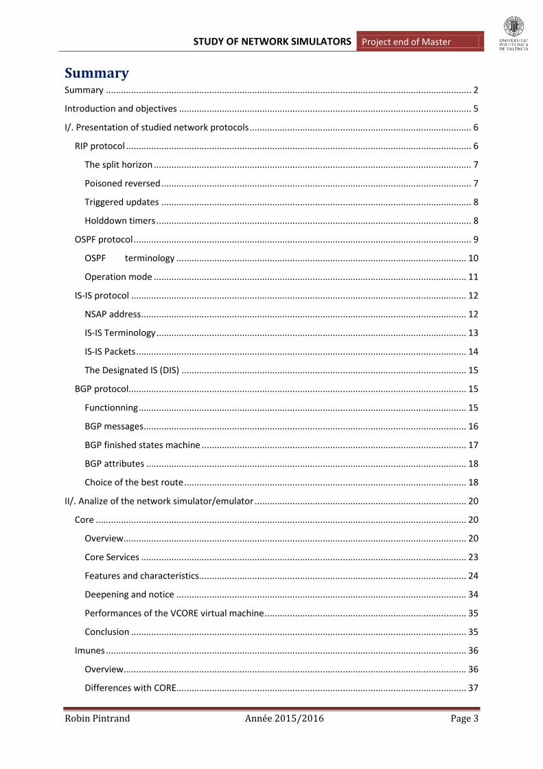
Summary Summary ................................................................................................................................................. 2
Introduction and objectives .................................................................................................................... 5
I/. Presentation of studied network protocols ........................................................................................ 6
RIP protocol ......................................................................................................................................... 6
The split horizon .............................................................................................................................. 7
Poisoned reversed ........................................................................................................................... 7
Triggered updates ........................................................................................................................... 8
Holddown timers ............................................................................................................................. 8
OSPF protocol ...................................................................................................................................... 9
OSPF terminology ................................................................................................................... 10
Operation mode ............................................................................................................................ 11
IS-IS protocol ..................................................................................................................................... 12
NSAP address ................................................................................................................................. 12
IS-IS Terminology ........................................................................................................................... 13
IS-IS Packets ................................................................................................................................... 14
The Designated IS (DIS) ................................................................................................................. 15
BGP protocol...................................................................................................................................... 15
Functionning .................................................................................................................................. 15
BGP messages ................................................................................................................................ 16
BGP finished states machine ......................................................................................................... 17
BGP attributes ............................................................................................................................... 18
Choice of the best route ................................................................................................................ 18
II/. Analize of the network simulator/emulator .................................................................................... 20
Core ................................................................................................................................................... 20
Overview ........................................................................................................................................ 20
Core Services ................................................................................................................................. 23
Features and characteristics .......................................................................................................... 24
Deepening and notice ................................................................................................................... 34
Performances of the VCORE virtual machine ................................................................................ 35
Conclusion ..................................................................................................................................... 35
Imunes ............................................................................................................................................... 36
Overview ........................................................................................................................................ 36
Differences with CORE ................................................................................................................... 37
STUDY OF NETWORK SIMULATORS Project end of Master
Robin Pintrand Année 2015/2016 Page 4
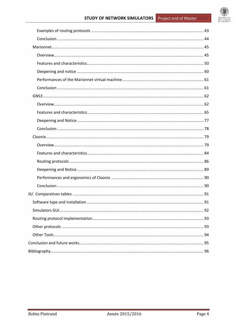
Examples of routing protocols ...................................................................................................... 43
Conclusion ..................................................................................................................................... 44
Marionnet .......................................................................................................................................... 45
Overview ........................................................................................................................................ 45
Features and characteristics .......................................................................................................... 50
Deepening and notice ................................................................................................................... 60
Performances of the Marionnet virtual machine .......................................................................... 61
Conclusion ..................................................................................................................................... 61
GNS3 .................................................................................................................................................. 62
Overview ........................................................................................................................................ 62
Features and characteristics .......................................................................................................... 65
Deepening and Notice ................................................................................................................... 77
Conclusion ..................................................................................................................................... 78
Cloonix ............................................................................................................................................... 79
Overview ........................................................................................................................................ 79
Features and characteristics .......................................................................................................... 84
Routing protocols .......................................................................................................................... 86
Deepening and Notice ................................................................................................................... 89
Performances and ergonomics of Cloonix .................................................................................... 90
Conclusion ..................................................................................................................................... 90
III/. Comparatives tables ....................................................................................................................... 91
Software type and installation .......................................................................................................... 91
Simulators GUI ................................................................................................................................... 92
Routing protocol implementation ..................................................................................................... 93
Other protocols ................................................................................................................................. 93
Other Tools ........................................................................................................................................ 94
Conclusion and future works................................................................................................................. 95
Bibliography ........................................................................................................................................... 96

STUDY OF NETWORK SIMULATORS Project end of Master
Robin Pintrand Année 2015/2016 Page 5
Introduction and objectives
For my last semester of Ingeneering School I should realise an ERASMUS exchange in Valencia, at the
Politecnical University of Valencia (UPV). During this semester I realized an end of master project
about the network science. Precisely, I worked on five OpenSource networks simulators. Simulators
allow the test of big networks without the problems of cost and human resources: indeed, it is
sometimes really difficult for companies to buy all the equipments needed to realize very complex
topology. Furthermore, the implementation, the configuration and the analysis of such installations
requires whole working teams. So the interest of this project is to propose an alternative solution
allowing working on networks without physical infrastructures.
The goal here was to evaluate each of them to see if they were usable to answer to this question:
How to create and manage a network without physical equipment.
The study and the tests were more oriented towards the support of four routing protocols: RIP,
OSPF, IS-IS and BGP. On each simulator, I had first to check the possibility to implement all of this
protocol. After that, the interest to evaluate the power of the five simulators was to create topology
mixing the different routing protocols. Thanks to that, it was possible to check the power of each of
them but also their scalability.
Furthermore, this works include a more general analyse to well differentiate the goal and the
implementation of each simulators. So, you will discover remarks about the grafical rendering, about
the security tools, the layers 2 issues, the performances, etc.
To begin, this report start with the presentation of the four routing protocols that will be
implemented in the simulator. The goal here is remind quickly the important features of each of
them before start the simulator’s benchmark.
OBJECTIVES:
According to the previous introduction, the objectives of this work are:
- Test of 5 network simulators :
o Analysis of the handling
o Analysis of the interface and the proposed tools
o Test of the four routing protocols
o Analyse of others protocols enabled: Ipsec, DNS, IPv6…
- Comparison of simulators.
- Reflection on potential improvements.

STUDY OF NETWORK SIMULATORS Project end of Master
Robin Pintrand Année 2015/2016 Page 6
I/. Presentation of studied network protocols
RIP protocol
The Routing Information Protocol defines a way for routers, which connect networks using the
Internet Protocol (IP), to share information about how to route traffic among networks. RIP is
classified by the Internet Engineering Task Force (IETF) as an Interior Gateway Protocol (IGP) that
seems it is used for routers moving traffic in an Autonomous System (AS). An AS is defined as a group
of IP networks with a coherent routing policy. For example a single enterprise's network that may be
comprised of many separate local area networks (LANs) linked through routers could use RIP. This
protocol has been created by the RFC 1058.
RIP is a distance-vector routing protocol using the Bellman-Ford algorithm to which path to put a
packet on to get to its destination. That mean each router sends all or part of its routing table in
routing updates. However, the updates are only sent to neighboring routers.
Image 1: Distance Vector Network Discovery
So, a routers using distance-vector protocol do not have knowledge of the entire path to a
destination. The paths are build hop-by-hop. By default, each router sends its table every 30 seconds
to its neigbhors. To do this, RIP use the transport protocol UDP, on the port 520.
RIP use the hop count as a metric: to choose the better path to join a destination, the protocol will
select the path which forces to make the least jump as possible (number of routers to be crossed).
Image 2: Hope count as a metric
The drawbacks of this method are that packets may be forced to take a slower route with fewer hops
over a faster route with more hops. Indeed, the hope count does not take into account the speed of
the router’s interfaces. The maximum metric value is 15 hops.
STUDY OF NETWORK SIMULATORS Project end of Master
Robin Pintrand Année 2015/2016 Page 7
This routing protocol is really simple to implement and need really few processor and memory
ressources. But the convergency is slow, the update take time to be propagated in the network,
because of the hop count as a metric. But the biggest problem of RIP is that is not implemented to
detect the routing loops.
A routing loop is a common problem with various types of networks, particularly computer
networks. They are formed when an error occurs in the operation of the routing algorithm, and as a
result, in a group of nodes, the path to a particular destination forms a loop. In the simplest version,
a routing loop of size two, node A thinks that the path to some destination (call it C) is through its
neighbouring node, node B. At the same time, node B thinks that the path to C starts at node A. Thus,
whenever traffic for C arrives at either A or B, it will loop endlessly between A and B, unless some
mechanism exists to prevent that behaviour.
To resist this problem, some features have been implemented on RIP:
The split horizon
It is a method of preventing routing loops in distance-vector routing protocols by prohibiting a
router from advertising a route back onto the interface from which it was learned. To explain it, let is
take an example.
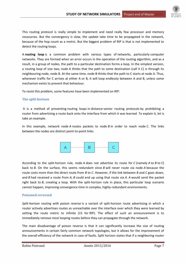
In this example, network node A routes packets to node B in order to reach node C. The links
between the nodes are distinct point-to-point links.
According to the split-horizon rule, node A does not advertise its route for C (namely A to B to C)
back to B. On the surface, this seems redundant since B will never route via node A because the
route costs more than the direct route from B to C. However, if the link between B and C goes down,
and B had received a route from A, B could end up using that route via A. A would send the packet
right back to B, creating a loop. With the split-horizon rule in place, this particular loop scenario
cannot happen, improving convergence time in complex, highly-redundant environments.
Poisoned reversed
Split-horizon routing with poison reverse is a variant of split-horizon route advertising in which a
router actively advertises routes as unreachable over the interface over which they were learned by
setting the route metric to infinite (15 for RIP). The effect of such an announcement is to
immediately remove most looping routes before they can propagate through the network.
The main disadvantage of poison reverse is that it can significantly increase the size of routing
announcements in certain fairly common network topologies, but it allows for the improvement of
the overall efficiency of the network in case of faults. Split horizon states that if a neighboring router

STUDY OF NETWORK SIMULATORS Project end of Master
Robin Pintrand Année 2015/2016 Page 8
sends a route to a router, the receiving router will not propagate this route back to the advertising
router on the same interface. With route poisoning, when a router detects that one of its connected
routes has failed, the router will poison the route by assigning an infinite metric to it and advertising
it to neighbors. When a router advertises a poisoned route to its neighbors, its neighbors break the
rule of split horizon and send back to the originator the same poisoned route, called a poison
reverse. In order to give the router enough time to propagate the poisoned route and to ensure that
no routing loops occur while propagation; the routers implement a hold-down mechanism.
Triggered updates
As we have seen that the previous mecanisms was slow, triggered updates are an attempt to speed
up this convergence. It consists to immediatly send to the router’s neighbors an update message
when the metric for a route change. Only after that, the effective update could be done. Thanks to
this, we do not have to wait the 30 seconds between updates. The neigbhors will do another new
update which will produce a new immediate send and it successively for all the affected routers.
Holddown timers
RIP use several timers, some of them are global and the others are associated to each entry in the
routing table.
Routing-update timer
It is the global timers which indicate when routers have to emit their routing table: each 30 seconds,
more a random number to avoid sincronization between routers.
Routing-timeout timer
This timer indicates the time that an entry can stay in the routing table without update, before being
marked as unreachable. This timer start after each uptdate and, by default, its value is 180 seconds.
Route-flush timer
It starts when a route turns to unreachable, because of a timeout or an update. At the end of the
timer, the route is permanently removed from the table. The default value is 120 seconds.
Hold-down timer
Timer associated to each table entry. Holddown timer works by having each router start a timer
when they first receive information about a network that is unreachable. Until the timer expires, the
router will discard any subsequent route messages that indicate the route is in fact reachable. It can
solve the case where multiple routers are connected indirectly.
A RIP packet is sent using this format:
Image 3 : RIP packet format

STUDY OF NETWORK SIMULATORS Project end of Master
Robin Pintrand Année 2015/2016 Page 9
Command : request/answer or diffusion. Version: RIP exists in version 1 or 2. Unused: all bits with the value 0. Adress Family Identifier: here the value is to because we use IP protocol. Route tag: allows distinguishing the routes learnt thanks to RIP or other protocols (BGP). IP address of the source. Subnet Mask. Next hope: IP address of the next hope’s interface. Metric : 1 to 15. 16 = unreachable.
To conclude with RIP protocol, it is important to notice that it does not support the use of subnets:
RIPv1 only know the three adress classes. If we want to use subnets, we have to implement the
version 2 of this protocol. With RIPv2 it is also possible to use multicast thankts to the address
224.0.0.9.
RIP has been supplanted mainly due to its simplicity and its inability to scale to very large and
complex networks. Other routing protocols push less information of their own onto the network,
while RIP pushes its whole routing table every 30 seconds. As a result, other protocols can converge
more quickly, use more sophisticated routing algorithms, include latency, packet loss, actual
monetary cost and other link characteristics, as well as hop count with arbitrary weighting.
OSPF protocol
Open Shortest Path First is also an interior gateway protocol (IGP) for routing Internet Protocol (IP)
packets solely within a single routing domain, such as an autonomous system. The RFC 2328 explain
all the features of this protocol. Unlike RIP, it use a link of state routing which is really different from
vector-distance: this routing use SPF algortihm (Dijkstra for OSPF) to discover the entire network.
That seem that all routershave the same entire view of the network topology. The table update is
now activated by events and not periodically. Thanks to that, there is not possible to have routing
loops but it is more difficult to configure and the processor, memory requierements are more
important. OSPF is a protocol without classes that means it support VLSM (we can use subnets
without problem). It is also possible to send multicast packages with the address 224.0.0.5.
The metric used with this protocol is based on the cost, which more represents the link capacity and
allows a better use of the bandwidth. The equation traducing the cost estimation is: cost= 10000
0000/bandwith in Bits/s.
OSPF is strutured in Autonomous System (AS), divided in Areas, to simplify administration and
optimize traffic and resource utilization. Areas are identified by 32-bit numbers, expressed either
simply in decimal, or often in octet-based dot-decimal notation, familiar from IPv4 address notation.
STUDY OF NETWORK SIMULATORS Project end of Master
Robin Pintrand Année 2015/2016 Page 10
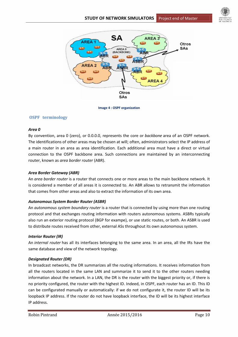
Image 4 : OSPF organization
OSPF terminology
Area 0
By convention, area 0 (zero), or 0.0.0.0, represents the core or backbone area of an OSPF network.
The identifications of other areas may be chosen at will; often, administrators select the IP address of
a main router in an area as area identification. Each additional area must have a direct or virtual
connection to the OSPF backbone area. Such connections are maintained by an interconnecting
router, known as area border router (ABR).
Area Border Gateway (ABR)
An area border router is a router that connects one or more areas to the main backbone network. It
is considered a member of all areas it is connected to. An ABR allows to retransmit the information
that comes from other areas and also to extract the information of its own area.
Autonomous System Border Router (ASBR)
An autonomous system boundary router is a router that is connected by using more than one routing
protocol and that exchanges routing information with routers autonomous systems. ASBRs typically
also run an exterior routing protocol (BGP for exampe), or use static routes, or both. An ASBR is used
to distribute routes received from other, external ASs throughout its own autonomous system.
Interior Router (IR)
An internal router has all its interfaces belonging to the same area. In an area, all the IRs have the
same database and view of the network topology.
Designated Router (DR)
In broadcast networks, the DR summarizes all the routing informations. It receives information from
all the routers located in the same LAN and summarize it to send it to the other routers needing
information about the network. In a LAN, the DR is the router with the biggest priority or, if there is
no priority configured, the router with the highest ID. Indeed, in OSPF, each router has an ID. This ID
can be configurated manually or automatically: if we do not configurate it, the router ID will be its
loopback IP address. If the router do not have loopback interface, the ID will be its highest interface
IP address.

STUDY OF NETWORK SIMULATORS Project end of Master
Robin Pintrand Année 2015/2016 Page 11
Backup Designated Router (BDR)
A backup designated router (BDR) is a router that becomes the designated router if the current
designated router has a problem or fails. The BDR is the OSPF router with second highest priority at
the time of the last election.
Operation mode
Unlike other routing protocols, OSPF does not carry data via a transport protocol, such as the User
Datagram Protocol (UDP) or the Transmission Control Protocol (TCP). Instead, OSPF forms IP
datagrams directly, packaging them using protocol number 89 for the IP Protocol field. OSPF defines
five different message types, for various types of communication:
HELLO protocol
Hello messages are used as a form of greeting, to allow a router to discover other adjacent routers
on its local links and networks. The messages establish relationships between neighboring devices
(called adjacencies) and communicate key parameters about how OSPF is to be used in the
autonomous system or area. Hello packets are emitted at regular intervals (10 or 30 seconds). This
protocol also allows to be sure that the neighbor’s routers stay activated.
After the connection between two routers activated, Link State Advertisement (LSA) can be emitted
when there is a topology change. There are four types of LSA:
Router Links
The router announces its presence and lists the links to other routers or networks in the same area,
together with the metrics to them. Router Links LSAs are flooded across their own area only. Each
interface generates one Router links. The link-state ID of this LSA type is the originating router ID.
Network Links
The designated router (DR) on a broadcast segment (Ethernet for example) lists which routers are
joined together by the segment. It is a summary generated after the reception of the Router Links of
the routers connected in the same LAN. Type 2 LSAs are flooded across their own area only. The link-
state ID of this LSA is the IP interface address of the DR.
Summary Links
An Area Border Router (ABR) takes information it has learned on one of its attached areas and
summarizes it before sending it out on other areas it is connected to. This summarization helps
provide scalability by removing detailed topology information for other areas, because their routing
information is summarized into just an address prefix and metric. The summarization process can
also be configured to remove a lot of detailed address prefixes and replace them with a single
summary prefix, helping scalability. The link-state ID is the destination network number for Network
Links LSAs.
External Links
STUDY OF NETWORK SIMULATORS Project end of Master
Robin Pintrand Année 2015/2016 Page 12
These LSAs is generated for the ASBR. It contains information imported into OSPF from other routing
processes. It allows to redirect this information in the area 0 and after, in the others. It also describes
the access information outside of the ASBR’s AS. The link-state ID of this LSA is the external network
number.
The actualization generated by events and LSAs flooding allow a convergency significantly better
than a protocol like RIP. It is important to notice that OSPF does not works in the same way for multi-
access (ethernet) and point-to-point (serial) netwoks:
Multi-access network: DR and multicast addresses will be used. Point-to-Point network: It does not use DR and unicast addresses will be use for each router.
To conclude, thanks to these performances, OSPF is perhaps the most widely used interior gateway
protocol (IGP) in large enterprise networks. But, provider networks also use another link-state
dynamic protocol: IS-IS.
IS-IS protocol
Intermediate System to Intermediate System is an internal routing protocol. It is defined in the
internatinal standard ISO 10589:2002 of the Open System Interconnection (OSI). Even if IS-IS is not
an internet standard, the Internet Engineering Task Force (IETF) published its features in the RFC
1142.
As OSPF IS-IS is a link of state protocol that we use in an autonomous system (AS). IS-IS routers have
a common view of their network. Packets are transmitted by the shortest route and the algorithm
used to estimate path is also the Dijkstra protocol. Conceptually, OSPF and IS-IS are the same: the
use variable size of network masks, they use multicast to discover the neighbor routers (01-80-C2-00-
00-14 or 01-80-C2-00-00-15 for IS-IS) using HELLO packets… But, OSPF is only an IP routing protocol
whereas IS-IS is an OSI routing protocol and do not use IP to transmit messages.
NSAP address
IS-IS does not use IP address but NSAP adresses. Network Service Access Point (NSAP) address is the
network-layer address for CLNS packets (Connectionless Network Service- CLNS is similar to IP
Service; a CLNS entity communicates using CLNP protocol with peer CLNS entity). NSAP addresses
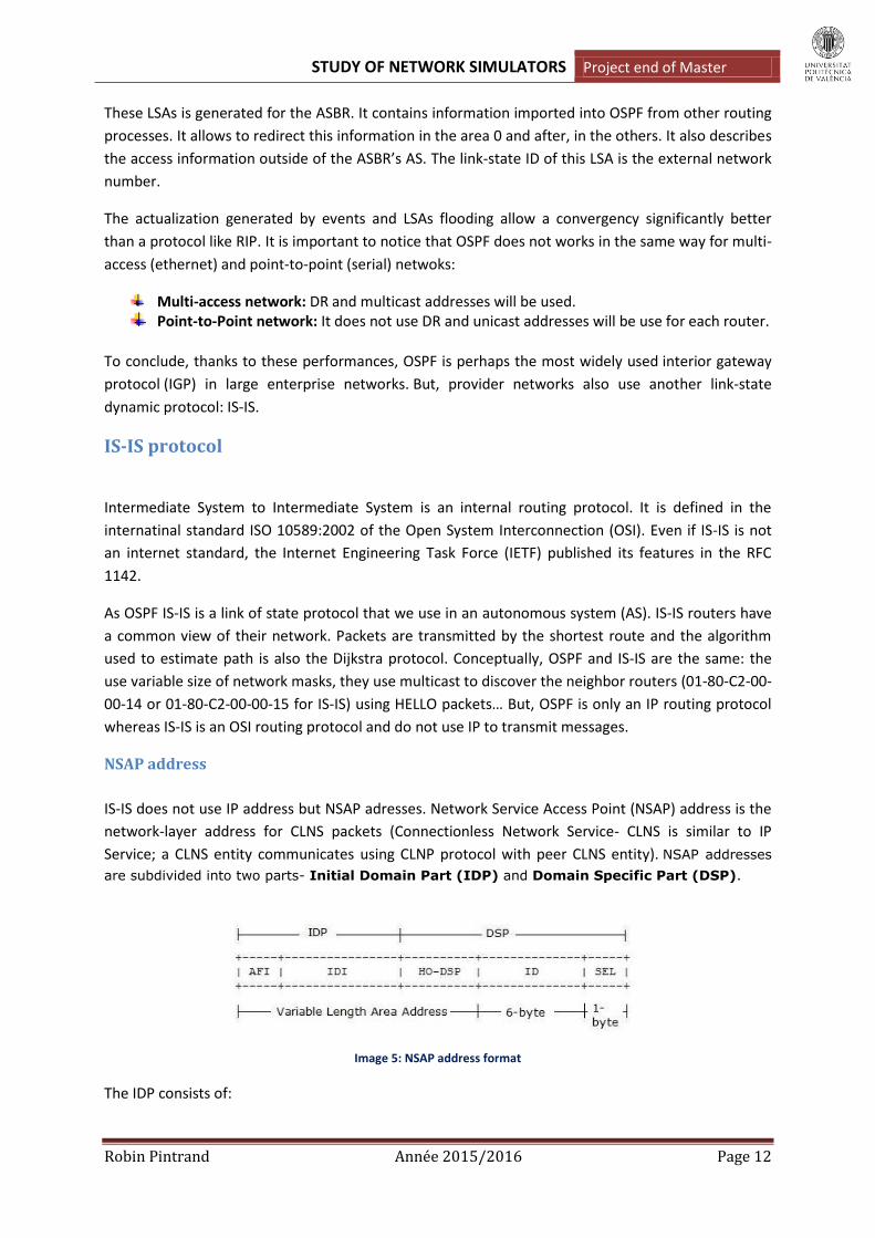
are subdivided into two parts- Initial Domain Part (IDP) and Domain Specific Part (DSP).
Image 5: NSAP address format
The IDP consists of:
STUDY OF NETWORK SIMULATORS Project end of Master
Robin Pintrand Année 2015/2016 Page 13
AFI: Authority and Format Identifier (1-byte). The AFI has a binary value between 0 and 99; this value identifies the IDI and DSP format. AFI set to 49 indicates private address space.
IDI : Initial Domain Identifier (variable length) The DSP consists of :
HO-DSP: High-Order of DSP. The may use any format as defined by the authority identified by IDP. The combination of [IDP, HO-DSP] identifies both the routing domain and the area within the routing domain. Hence the combination [IDP, HO-DSP] is called the "Area Address". All nodes within the area must have same Area address.
ID : System Identifier (6 bytes). SEL : NSAP Selector (1 byte).
When we define an IS-IS router we have to assignate it a Network Entity Title (NET) which is an NSAP
address with SEL set to 0. This parameter have to be set to 0 for all IS-IS routers. The following is
sample NET: 49.0001.1111.1111.1111.00. Be careful, it is one NSAP per router, not per inteface. The
different parts are :
Area address = 49.0001 (the number 49 is the AFI). System ID = 1111.1111.1111 NSEL = 00
IS-IS Terminology
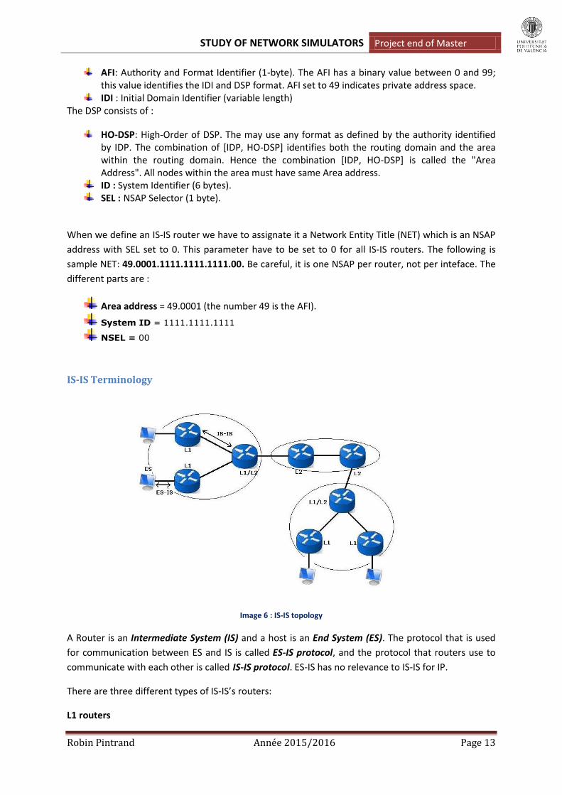
Image 6 : IS-IS topology
A Router is an Intermediate System (IS) and a host is an End System (ES). The protocol that is used
for communication between ES and IS is called ES-IS protocol, and the protocol that routers use to
communicate with each other is called IS-IS protocol. ES-IS has no relevance to IS-IS for IP.
There are three different types of IS-IS’s routers:
L1 routers

STUDY OF NETWORK SIMULATORS Project end of Master
Robin Pintrand Année 2015/2016 Page 14
Level 1 routers are routers that have no direct connectivity with another area: all its interfaces are in
the same area. These routers maintain L1 link-state database. They are analogous to OSPF non
backbone Internal Routers.
L2 routers
Level 2 routers are routers that connect the areas to the backbone. These routers maintain a L2 link-
state database. We can assimilate them to the OSPF backbone routers or the ASBR.
L1/L2 routers
L1/L2 routers are analogous to OSPF ABRs. These L1/L2 routers maintain a separate L1 link-state
database and L2 link-state database. These routers can connect to L1 and L2 routers.
The set of L2 routers (including L1/L2 routers) and their interconnecting links is the IS-IS
Backbone. Every L1 router within an area maintains a link-state database. L1/L2 routers do not
advertise L2 routes to L1 routers.
To route a packet to another area, an L1 router must forward the packet to L1/L2 router.
An important point to notice is that IS-IS L1/L2 routers does not have to two NET addresses as it is
the wase withe OSPF: even if the allow the connection between two areas (with IS-IS the words
« Routing Domain » are more used), they are only in one of them and so need only one NET address.
IS-IS Packets
With IS-IS, packets are referred to as Protocol Data Units (PDUs). There are 3 categories of IS-IS’s
packets:
HELLO PDU
IS-IS Hello packets are used to discover neighbors on a link. Once the neighbors are discovered, they
act as keepalive messages to maintain the adjacency. IS-IS standard recommends that IS-IS Hello
packets must be padded to within one octet less than the size of the MTU.
There are two types of Hello packets: LAN Hellos and Point-to-point Hellos. LAN Hellos are of further
two types- Level-1 and Level-2 LAN Hellos. Both LAN Hellos are identical in format. This PDU is really
similar to the HELLO packet used by OSPF.
Link State PDUs (LSPs)
These packets are responsible to distribute routing information between IS-IS nodes. Like OSPF LSAs,
IS-IS uses LSPs to distribute and exchange routing information between IS-IS nodes. An IS-IS router
floods an LSP throughout an area to identify its adjacencies and their states, and address prefixes
that it can reach. L1 and L2 LSP packet formats are same.
Sequence Number PDUs (SNPs)
These packets control the distribution of LSPs. SNPs provide mechanism to synchronize link State
Data Base between routers in the same area. They describe some or all of the LSPs in the database.

STUDY OF NETWORK SIMULATORS Project end of Master
Robin Pintrand Année 2015/2016 Page 15
The Designated IS (DIS)
As with OSPF, IS-IS use a designated router. The DIS is only on LANs, not on P2P. The DIS have two
tasks :
Create and update LSP. Conduct flooding over the LAN.
The DIS periodically multicasts Complete SNP (CSNP) to describe all the LSPs in the database. L1
CSNPs are sent to all Level-1 ISs multicast address 01-80-C2-00-00-14, while L2 CSNPs are sent to all
Level-2 ISs multicast address 01-80-C2-00-00-15.
In IS-IS there is no Backup DIS. The DIS is elected by the highest priority or the highest MAC address.
The command to see who is DIS in a LAN is: « show clns interface ».
To summarize, OSPF being more popular, it offers more extensions than IS-IS. However, IS-IS is more
thrifty and adapts himself better to the most vast networks. With the same capacity, IS-IS can work
with more routers in an area than OSPF. Furthermore, IS-IS is multi-protocol, that allows him to not
only route IP packets.
BGP protocol
Border Gateway Protocol (BGP) is a standardized exterior gateway protocol designed to exchange
routing and reachability information among autonomous systems (AS) on the Internet. It allows the
interconnection between LAN using IGP. Unlike the IGP like RIP, OSPF or IS-IS, BGP does not use
classic metrics but bases the routing decisions on the traveled paths, the attributes of prefixes and a
set of rules of selection defined by the administrator of the AS. We qualify him as a path vector
protocol. This type of protocol uses the Bellman Ford algorithm.
BGP allows the routing without class and use the aggregation of roads to limit the size of the routing
tables. Since 1994, the version 4 of the protocol is used on the Internet, the previous ones being
considered as obsolete. Its specifications are described in the RFC 4271 A Border Gateway Protocol 4
(BGP-4). BGP has a lot of specifications, for example the RFC 2545 allows IPv6 routes and the RFC
2858 is the multi-protocol extension.
Functionning
The connections between two BGP neighbors (neighbors or peers) are explicitly configured between
two routers. That means the neigbhors discovery is not automatics as with the protocols seen
previously: we have to explicitly declare it. After that, the routers communicate between them via a
TCP session on the port 179 initiated by one of the two routers .BGP is the only routing protocol
which use TCP as transport protocol.
There are two versions of BGP: Interior BGP (iBGP) and Exterior BGP (eBGP). IBGP is used inside
Autonomous System while eBGP is used between two AS.

STUDY OF NETWORK SIMULATORS Project end of Master
Robin Pintrand Année 2015/2016 Page 16
Image 7: BGP architecture
Generally, the eBGP connections are established with Pont-To-Point connections or on local
networks (an Internet Exchanges for example), the TTL of the packages of the session BGP is then
fixed to 1. If the physical connection is broken, the eBGP session also is, and all the prefixes learnt by
this one are announced as deleted and removed from the routing table.
Conversely, the iBGP connections are generally established between logical addresses not associated
with a particular physical interface. This allows, in case of break of a physical link, to keep the iBGP
active session if an alternative link exists and if a dynamic internal routing protocol ( IGP) is used (for
example OSPF). In the study of the simulator, we will see that I did not use iBGP but directly an IGP:
the goal here will be to see how the interconnection between routing protocols works.
Once the connection between two routers is established, they exchange information about the
networks they know and for whom they propose some traffic, as well as a number of attributes
associated to these networks which are going to allow to avoid loops (as the AS Path) and to choose
the best road.
BGP messages
BGP use five kinds of messages:
OPEN: this message is used when the TCP connection is established between two BGP neighbors. It allows exchanging informations as AS numbers and negociate capacity of each peer.
KEEPALIVE: maintain the session opened. By default, one KEEPALIVE message is emitted each 30 seconds. A delay of 90 without KEEPALIVE or UPDATE message received causes the session closure.
UPDATE: this message allows announce of the new routes or routes retirement. NOTIFICATION: end of BGP session message due to an error. ROUTE-REFFRESH: defined in the RFC 2918. Thanks to that, the refreshment capacity of
roads is negotiated in the OPEN message and allows asking to reannounce certain prefixes after a modification of the filtering politics.

STUDY OF NETWORK SIMULATORS Project end of Master
Robin Pintrand Année 2015/2016 Page 17
Image 8: BGPmessage type
BGP finished states machine
The software allowing managing the exchanges of road has to implement a finished automaton
composed by six states bound by thirteen events. Automatons have a dialogue between them by
messages (OPEN, KEEPALIVE, UPDATE and NOTIFICATION).
Image 9: BGP automaton diagram
The changes of states and the behavior waited are the following ones:
Idle
In this state, the process refuses the connections and assigns no resource. When the event of starting
up (manual or automatic) is received, the process introduces the resources and a connection with
the configured neighbors, and listens to the entrantes connections on the port TCP 179 and falls over
to the state Connect. In case of error, the connection is cut and the process returns to the state Idle.
Connect
Waits that the connection TCP is established, then sends the OPEN message and falls over to the
state OpenSent. In case of error, waits a predefined deadline and continuous to listen to on the port
179. After that, it falls over to the state Active.
Active
Try to establish a TCP connection with the neighbor. In case of success, send the OPEN message and
falls over to the state Connect, any other event causes the return in the state Idle.
OpenSent
STUDY OF NETWORK SIMULATORS Project end of Master
Robin Pintrand Année 2015/2016 Page 18
The OPEN message was sent, waits for the OPEN message in return and if there is not an error, sends
a KEEPALIVE and tips over to OpenConfirm. In the other cases, sends a NOTIFICATION message and
returns to the state Idle.
OpenConfirm
Waits for a KEEPALIVE message and then go to the Established state. But if we receive a
NOTIFICATION message, returns to the state Idle.
Established
The connection BGP is established, UPDATE and KEEPALIVE messages can be exchanged. A
NOTIFICATION message causes the return in the state Idle.
BGP attributes
Each BGP prefix is associated with a various number of attributes. Attibutes are classified en 4
different types :
Well-Known Mandatory (WM): These attributes must be taken care and propagated. Well-Known Discretionary (WD): Must be taken care, the distribution is optional. Optional Transitive (OT): not inevitably taken care but propagated. Optional Nontransitive (ON): Not inevitably taken care nor propagated, can be completely
ignored if they are not managed.
There are a lot of attributes in BGP but the moste important are:
AS Path
Orderly list of the crossed Autonomous Systems (AS). The attribute AS Path allows avoiding loops. If a
road is received from a neighbor eBGP with its own AS in the AS Path, then the road is rejected.
Local Preference
Metrics intended for the internal routers to prefer certain external routes. It is the preference inside
one AS.
Next Hope
When a prefix is announced to an eBGP neighbor, the attribute Next Hop represents the IP address
of exit towards this neighbor. This attribute is not altered when it is transmitted to the iBGP
neighbors; this implies that the road towards the IP address of the eBGP neighbor is known via an
IGP. If it is not the case, the road BGP is marked as unusable.
Origin
Origin of the router. It can be learnt from an EGP as BGP or from an IGP as IS-IS for example.
Choice of the best route
BGP uses a much more evolved system than the IGP to choose the routes. Roads announced by the
BGP neighbors are possibly filtered and rejected or marked by altering the attributes of its roads. The
BGP table is built by comparing roads received for every prefix by choosing the best road. Only the
best road will be used in the routing table and announced to the neighbors as far as the exit filter of
allows it.
STUDY OF NETWORK SIMULATORS Project end of Master
Robin Pintrand Année 2015/2016 Page 19
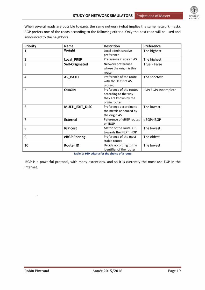
When several roads are possible towards the same network (what implies the same network mask),
BGP prefers one of the roads according to the following criteria. Only the best road will be used and
announced to the neighbors.
Priority Name Descrition Preference
1 Weight Local administrative preference
The highest
2 Local_PREF Preference inside an AS The highest
3 Self-Originated Network preference whose the origin is this router
True > False
4 AS_PATH Preference of the route with the least of AS crossed
The shortest
5 ORIGIN Preference of the routes according to the way they are known by the origin router
IGP>EGP>Incomplete
6 MULTI_EXIT_DISC Preference according to the metric annouced by the origin AS
The lowest
7 External Peference of eBGP routes on iBGP
eBGP>iBGP
8 IGP cost Metric of the route IGP towards the NEXT_HOP
The lowest
9 eBGP Peering Preference of the most stable routes
The oldest
10 Router ID Decide according to the identifier of the router
The lowest
Table 1: BGP criteria for the choice of a route
BGP is a powerful protocol, with many extentions, and so it is currently the most use EGP in the
Internet.
.

STUDY OF NETWORK SIMULATORS Project end of Master
Robin Pintrand Année 2015/2016 Page 20
II/. Analize of the network simulator/emulator
Core
CORE has been developed by a Network Technology research group that is part of the Boeing
Research and Technology division. The Naval Research Laboratory is supporting further development
of this open source project.
To use Core we have to respect some prerequisites:
Run on Linux or FreeBSD.
VM properties for CORE 4.7 :
o Storage: 1024 Mo
o IS : Ubuntu 32 bits
o Processor : 2
o RAM : 12Mo
The CORE project provides a virtual machine disk image called VCORE than can run in VirtualBox. This is a simple way to evaluate CORE. The file is very large – almost 600 megabytes – but it provides a fully-functional lubuntu system running CORE in a virtual machine on your PC. This allows us to quickly test CORE: you just have to download the zipped file and open the file named vcore-4.7.vbox with the VirtualBox software.
Notice that despite its name, Core simulates the action of the differents nodes composing a network and not emulate them. Indeed, for example, the routers do not work as real router: we will see before that they use services, written by the Core workgroup to, simulate routing protocols.
Overview
Core simulator is based on a GUI which proposes all the tools possible to create a network:
Image 10: Core's GUI

STUDY OF NETWORK SIMULATORS Project end of Master
Robin Pintrand Année 2015/2016 Page 21
There are two modes: The Edition and Execution Mode.
Edition Mode
It permits to create our network and customize the graphic depiction. The GUI allows doing a lot of things: we can rename the nodes, draw several figures to well understand the network, chose the colors, write some text… In this mode the network is not working, so it is impossible to test ping, traceroute or others managing commands.
To make your own network you have the choice between the following equipments:
Routers :
PCs :
Hubs :
Switchs :
Physical interfaces: RJ 45 node. The RJ45 node in CORE represents a physical interface on the real CORE machine. Any real-world network device can be connected to the interface and communicate with the CORE nodes in real time. The main drawback is that one physical interface is required for each connection. When the physical interface is assigned to CORE, it may not be used for anything else. Another consideration is that the computer or network that you are connecting to must be co-located with the CORE machine.
Tunnels: The tunnel tool builds GRE tunnels between CORE emulations or other hosts. Tunneling can be helpful when the number of physical interfaces is limited or when the peer is located on a different network. Also a physical interface does not need to be dedicated to CORE as with the RJ45 tool.
Links :
Wireless LAN :
Wifi routers :
Hosts :
STUDY OF NETWORK SIMULATORS Project end of Master
Robin Pintrand Année 2015/2016 Page 22
Execution mode
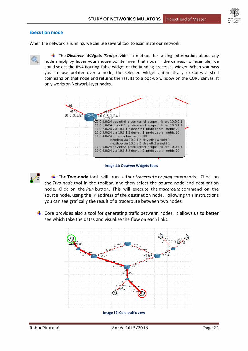
When the network is running, we can use several tool to examinate our network:
The Observer Widgets Tool provides a method for seeing information about any node simply by hover your mouse pointer over that node in the canvas. For example, we could select the IPv4 Routing Table widget or the Running processes widget. When you pass your mouse pointer over a node, the selected widget automatically executes a shell command on that node and returns the results to a pop-up window on the CORE canvas. It only works on Network-layer nodes.
Image 11: Observer Widgets Tools
The Two-node tool will run either traceroute or ping commands. Click on the Two-node tool in the toolbar, and then select the source node and destination node. Click on the Run button. This will execute the traceroute command on the source node, using the IP address of the destination node. Following this instructions you can see grafically the result of a traceroute between two nodes.
Core provides also a tool for generating trafic betwenn nodes. It allows us to better see which take the datas and visualize the flow on each links.
Image 12: Core traffic view

STUDY OF NETWORK SIMULATORS Project end of Master
Robin Pintrand Année 2015/2016 Page 23
Core Services
The way to use this simulator is really grafical: during the simulator test we have understood that it is not possible to use the terminal to configure a network.It will just allow us to notice that the network works properly with the managing command.
It is because Core is based on Core Services.This feature configures and starts processes on each node in our network. This processes are based on Python scripts, store in the arborescence of file of Core. Because CORE implements its virtual nodes using a lightweight virtualization technology called Linux namespaces, we cannot use the normal init or upstart scripts to start networking daemons on these nodes. We must use CORE Services. The list of the services available is the following:
Image 13: Core Services
Of course, each node, such as a router or a PC, has a set of CORE services already configured by default. More services may be selected. Some services are usable by only one type of node: for example, the services that implement network protocols can only be use by the routers.
So to create our network we have to use these different services. If we have to create a specifical configuration, Core allows us to customize its services. That is how we can create network using different Autonomous systems, OSPF areas, etc.
The use of the routing protocols is allowed by Zebra: it is an open sorce tool whixh regroup several management systems of routing protocols. The Zebra daemon takes up to update the diffferent routing tables. Futhermore, it offers tools to remotely inspect all the zebra’s devices. Zebra allows also defining static route, filtering rules… That is why the service will be always activated on the routers we use.

STUDY OF NETWORK SIMULATORS Project end of Master
Robin Pintrand Année 2015/2016 Page 24
Finally, the service « vtysh » allow the user to use a terminal for each node. The syntax is similar to that of Cisco routers. In fact, this service uses the Quagga daemon. All the nodes communicate with Quagga which communicate after with the OS. So, Core simulator uses the Quagga daemon to allow the user to configurate each node of a network.
Remark: as we can see on the IMAGE 2, we can also use BIRD instead of Quagga to create a router.
Features and characteristics
Links configuration
With this simulator we can not choose the type of a link: Core only offers to use ethernet links. But every links can be configurated very precisly. So it is possible to simulate numerous examples packet loss, duplicate, delay, jitter… It is also possible to change the color of the link and its width.
Image 14: link configuration page
Swtichs and hubs
They are only defined by a name. We can not activate any services on them. For example the Spanning-Tree portocol is not available: so it is impossible to create networks with loops. Because of misses of features, switchs and hubs have a very limited utility.
Image 15: Switch configuration page

STUDY OF NETWORK SIMULATORS Project end of Master
Robin Pintrand Année 2015/2016 Page 25
Routers
They are defined by a name and the adresses or their different interfaces. By default, each interface has to adresses: one Ipv4 and one IPv6. We can change the addresses proposed or delete one of the two. You do not choose the interface number, they are automatically created each time you creat a new link towards another node.
Image 16: Router configuration page
Each router can be configured: we have seen before that we could choose different services. By default only the OSPF protocols and the Ip forwarding is activated, but you can choose others:
Image 17: Routers services

STUDY OF NETWORK SIMULATORS Project end of Master
Robin Pintrand Année 2015/2016 Page 26
On this example we can see that the router use two routing protocols: OSPFv2 and BGP. Automatically, Core proposes a default configuration for these protocols. But if, we need to configure more in details we just have to use the zebbra interface which allow us to enter all the commands needed:
Image 18: zebbra interface
This interface looks like the « show run » command on a Cisco device. But here we can write or delete lines. For example, we see here that we have defined AS number, OSPF area, redistribtion of the BGP routes, etc. That is how Core allows us to customize a network configuration: we can not use the terminal.
Now we are going to speak about the functionnality that allowed Core Simulator’s routers:
Laboratory routing protocols:
First of all, Core’s routers allow the use of differents laboratory routing protocols:
NHDP: The Neighborhood Discovery Protocol (NHDP, RFC 6130) provides two-hop neighborhood discovery for mobile IP based networks. The different tests maked did not show the benefit of this protocol.
SMF: The Simplified Multicast Forwarding (SMF) provides basic Internet Protocol multicast forwarding suitable for use in wireless mesh and mobile ad hoc networks (MANET). It is described by (RFC 6621).The goal of this effort is to provide an implementation of experimental techniques for robust, efficient distribution of broadcast or multicast packets in dynamic, wireless networks such as Mobile Ad-hoc Networks.
OLSR: The Optimized Link State Routing (OLSR) protocol a routing protocol for wireless mesh and mobile ad hoc networks (MANET) and is described in RFC 3626.CORE is, by default, set up to use the NRL implementation.

STUDY OF NETWORK SIMULATORS Project end of Master
Robin Pintrand Année 2015/2016 Page 27
Security: At the level of the security, Core’s router can implement IPsec. Activating the IPsec service, you can create tunnel between the specified peers using the racoon IKEv2 keying daemon. You need to provide keys and the addresses of peers, along with the subnets to tunnel. I present an example with the network below:
Image 19: Network using IPsec tunnels
The idear here is to crypt all the informations which circulate between to server in the same tunnel. For example here I crypt the information between n6 and n7: the traceroute is always possible but the information is not visible anymore. To do it, I had to use the IPsec configuration window on the routers n4 and n3. On this window I configurated the tunnels endpoints and the networks to be encrypted the datas. To visualize it, here is the n4 IPsec configuration:
Image 20: n4 IPsec configuration

STUDY OF NETWORK SIMULATORS Project end of Master
Robin Pintrand Année 2015/2016 Page 28
So, we see that I configurated the window to mean I wanted to encrypted the informations beetwen the network 10.0.4.0/24 and 10.0.6.0/24 and the other entire network in the tunnel 1. Unfortunately, the managing commands do not work to see the IPsec functionning.
Core Simulator allows also implementing firewall rules on the routers. They are based on iptables commands. Activating the firewall services, we can customize a configuration file that allows us to manage the data traffic. In the configuration window, we have several samples of iptables rules commented: so we just have to uncomment those who interest us or create new ones. For example, on the configuration below I have disable the incoming ping but the outcoming ping are always enable. So the network inside could ping other nodes but it will be unreachable by outside.
Image 21: Example of iptables configuration
MDR routers:
Finally we have the possibility to use router specially designed to manage wifi networks.
The use remain the same, but the routers MDR communicate with Wifi, we dont have to create a link. They automatically detect their neighbors and a Wifi link is created in green.

STUDY OF NETWORK SIMULATORS Project end of Master
Robin Pintrand Année 2015/2016 Page 29
Image 22: Wifi network using MDR routers
Hosts
Defined by a name and their interface addresses, they can fill many roles:
DHCP server/client. FTP server. HTTP server. VPN server: it is the only one you need a manual configuration. We have to inform the
subnet address from which the client VPN IP will be allocated, the public address of the vpn server and and private subnet reachable behind our VPN server.
Image 23: VPN configuration

STUDY OF NETWORK SIMULATORS Project end of Master
Robin Pintrand Année 2015/2016 Page 30
Computers
By default, they are defined by a name and two adresses IP: one IPv4 and one IPv6. We can change the addresses proposed or delete one of the two. We can use PCs as routers thanks to the « IP forwarding » service. In this case Core will add automatically others ethernet interfaces.
Image 24: Computers configuration
Of course, when the computer is use as a router, it can use all the routers functionnalities.
Protocoles
With Core’s network, we can implement three types of routing protocols:
RIP: we can also use RIPNG, which is an extension of RIP allowing IPv6. RIPv2 is not available.
OSPF: with OSPF, OSPFv2 and OSPFv3MDR. The last is use to Wifi networks.
BGP: only the original version for this one.
The RIP do not need any configuration, by default it works on the routers you creat. The only manipulation is to activate it in the routers services. So I am not going to show an example because it does not have interess.
For the OSPF routing it is different: by default, Core can build an OSPF configuration who works. But, it automatically places all the routers in the same area: thing that we do not want when we build a complex network. It that case, we have to write some configuration lines in the zebbra router’s window. Let us take an exemple of multi-areas OSPF network:

STUDY OF NETWORK SIMULATORS Project end of Master
Robin Pintrand Année 2015/2016 Page 31
Image 25: Example of OSPF multi-area network
Here we can see that there are 4 OSPF areas, but by default, Core network do not understand our purpose. As shown on the image below, the router R8 thinks that all its network neighbors are in the area 0. So, if we want to realize an exemple more complex, we have to customize it: the networks 10.0.13.0/24 and 10.0.12.0/24 are in the area 0, and networks 10.0.18.0/24 and 10.0.20.0/24 in the area 2.
Image 26: R8 configuration by default / configuration OSPF multi-area

STUDY OF NETWORK SIMULATORS Project end of Master
Robin Pintrand Année 2015/2016 Page 32
And we have to do this operation for all the routers by respecting well our basic network plan. After this we can run our network and go to the Execution mode. It is at this moment that ther terminal will be usefull: it allows us to analize the routing tables and make sure that the protocol is well implemented.
Image 27: OSPF routes
We can see that our network is prefectly viable: our ABR know all the subnetworks and the differents routes are well broadcasted. All managing commands are usable, so we can also visualize more in detail the OSPF functionning.
Image 28: OSPF R8 neighbors
Using the « show ip ospf neighbor » command, we see that the Designed and Backup routers (DR) for R8. So Core allows a closer examination of networks, as if we worked on a physical environment.
Finally, we can test the communication from start to finish by trying a traceroute between PC5 and PC 7.
Image 29: Traceroute between PC 5 and 7
STUDY OF NETWORK SIMULATORS Project end of Master
Robin Pintrand Année 2015/2016 Page 33
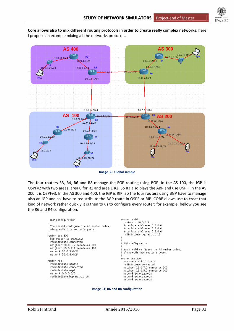
Core allows also to mix different routing protocols in order to create really complex networks: here I propose an example mixing all the networks protocols.
Image 30: Global sample
The four routers R3, R4, R6 and R8 manage the EGP routing using BGP. In the AS 100, the IGP is OSPFv2 with two areas: area 0 for R1 and area 1 R2. So R3 also plays the ABR and use OSPF. In the AS 200 it is OSPFv3. In the AS 300 and 400, the IGP is RIP. So the four routers using BGP have to manage also an IGP and so, have to redistribute the BGP route in OSPF or RIP. CORE allows use to creat that kind of network rather quickly it is then to us to configure every router: for example, bellow you see the R6 and R4 configuration.
Image 31: R6 and R4 configuration

STUDY OF NETWORK SIMULATORS Project end of Master
Robin Pintrand Année 2015/2016 Page 34
So we see that to configure BGP using CORE, we need to write and customize four kinds of informations: number of BGP Autonomous System, BGP neighbors, network located in the AS and redistribution of the BGP routes in the AS. Respecting this, we can test our network.
IMAGE 32: Routes of a BGP and a OSPF routers
As shown by the images, the routes are well redistributed and communicated following the protocol used by the router. Finally we try a ping between PC4 and H1 to validate our example:
Image 33: ping between PC4 and H1
Deepening and notice
Wireshark:
The coupling between CORE and wireshark do not work. Indeed the VCORE virtual machine does not
appear to have all the software installed that CORE requires. The tool has a menu command to
launch Wireshark to monitor traffic on a specified link but Wireshark is not available in the VCORE
virtual machine so the command fails.
IPv6 address:
Core allows the use of IPv6. By default, when we create a network it creat at the same time an ipv4 address and an ipv6 address for a node. So, if we want to do an example with only IPv6 addresses we just have to delete the others in the configuration tool of our node. After, the different manipulations are exactly the same as an example in IPv4. But we have to be careful with the

STUDY OF NETWORK SIMULATORS Project end of Master
Robin Pintrand Année 2015/2016 Page 35
protocol we choose: it have to support IPv6 address. So we can not use RIP or OSPFv2 protocol. The example below have been made with the protocol OSPFv3 so.
Image 34: IPv6 configuration
Performances of the VCORE virtual machine:
As said before, the fact that we can download directly a VM with all the dependencies of Core is really convenient. We can start our test very quickly without difficulty to install the software. But, the problem is that the VCORE virtual machine does not appear to have all the software installed that CORE requires. For example, the tool has a menu command to launch Wireshark to monitor traffic on a specified link but Wireshark is not available in the VCORE virtual machine so the command fails. Also, the DHCP server software is not installed. XORP is not installed. So it would be a good thing to work again on the conception of the VM: to verify if all dependencies are really in and settle some bugs.
Performance is quiet poor: when we start in Execution mode a network, we have to wait almost 30 seconds those routes are communicated. Sometimes the traceroute command failed without any reason. But, it does not ruin the experience. Furthermore, the CORE documentation suggests that performance will be poor when running CORE in a virtual machine, so this may improve when CORE is installed on a native Linux host computer.
Conclusion
Core offers an attractive graphical user interface that facilities setting up a network of virtual machines. It can destabilize at the start but the handling is quiet quick. Thanks to the GUI we can build big networks with a good graphics rendering: a loot of tools allow you to personalize your creation.
At the level of the usable routing protocol we will regret their number: only BGP, OSPF and RIP are implemented. But their functionning is OK and we can completely explore their possibilities. The performances are not great but enough to test it without problem.
This simulator offers some possibilites in terms of security with IPsec and Iptables commands. Theconfiguration of the links is also very precise and we can use IPv6 addresses to realize test.
STUDY OF NETWORK SIMULATORS Project end of Master
Robin Pintrand Année 2015/2016 Page 36
We shall miss certain functionalities; In particular the Wireshark tool which seems bad implemented or without the dependencies needed. Another problem is that, sometimes, the configuration is not reactive: you customize a configuration which had already been modified and the simulator does not take it into account. You have to return to the default configuration and reconfigure the work since the start, which can be sort of awkward.
Imunes
This simulator has been created at the University of Zagreb, by a team of ressearchers.
To use Imunes we have to respect some prerequisites:
Onlyrunwith FreeBSD.
VM properties for IMUNES :
o Storage : 1024 Mo
o IS : FreeBSD (32 bits)
o Processor : 2
o RAM : 9 Mo
AS Core, the IMUNES project provides a virtual appliance which allows evaluating the simulator.
Sowe just have to run this appliance on VirtualBox to use it, really quick and really simple.
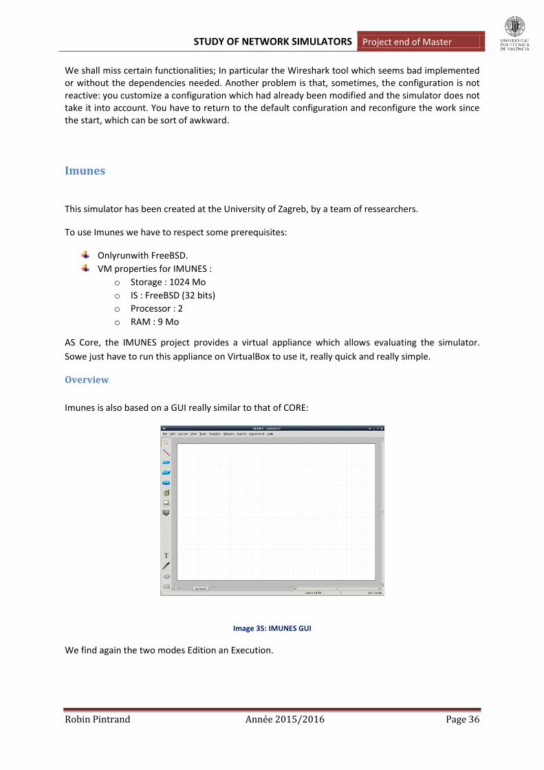
Overview
Imunes is also based on a GUI really similar to that of CORE:
Image 35: IMUNES GUI
We find again the two modes Edition an Execution.

STUDY OF NETWORK SIMULATORS Project end of Master
Robin Pintrand Année 2015/2016 Page 37
Edition Mode
It does the same works that for CORE. But, here we have less equipment: we ca not use wifi routers,
Wifi LAN and tunnel builder. We also can create several geometrical figures and text to customize the
network we are creating.
We can find here as on Core:
(Link, hub, switch, router, host, PC, physical interface)
Execution Mode
Here too, we have fewer tools than with Core. We only have the widget that allows us to see
information nodes when the mouse is moving other a node. It is impossible to highligth a link or
doing a traceroute by a graphic way.
Image 36: Links highligth
The only difference we can see with Core is that we can see the configuration window of a node even
if we are in Execution mode. But, it is impossible to modify it so it is not a great benefit.
As we can easily see, IMUNES is really similar to CoreEmulator Network. So I’m not going to explain
again the same functionnalities. I will just explain the differences there are beetwen the two
emulators what will allow us to judge the quality of one to another.
Differences with CORE
About the proposed services
The biggest differency between the two emulators is about the services proposed: we have seen
before that Core allowed a lot of possibility for everykind of nodes (firewall, DHCP, IPforwarding,
IPsec…). All this services was pre-configurated and we just had to activate them thanks to the
Services page. With IMUNES, there is only one script implemented by default which allows using
DHCP on the host nodes. For the others, we can just activate a routing protocol on the routers,
nothing for the PCs, nothing for the switch.

STUDY OF NETWORK SIMULATORS Project end of Master
Robin Pintrand Année 2015/2016 Page 38
About the nodes customization
As CORE, IMUNES configures automatically the nodes with a name and two IP addresses for
eachnode (IPv4 and IPv6). We can customize it of course, but we have also more possibilities to
manage the interfaces:
Image 37: node configuration window
The GUI allows severals manual functionnalties that was no available with CORE:
We can manually shutdown the interfaces.
Choose the MTU length.
Choose the kind of queue :
o FIFO
o DRR
o WFQ
Configurate the packet size.
Choose the queue management algortihm :
o Dropt-tail
o Drop-head
About the routers
As said before, we have fewer possibilities with IMUNES:
Image 38: IMMUNES router’s services
STUDY OF NETWORK SIMULATORS Project end of Master
Robin Pintrand Année 2015/2016 Page 39
We can select one of the three routers model available: quagga is the same that with Core. The
problem is that xorp is not installed on the virtual appliance. The is only two kind of protocols
available :
RIP: withits first and RIPng for using IPv6 addresses.
OPSF: version 2 or 3 for IPv6.
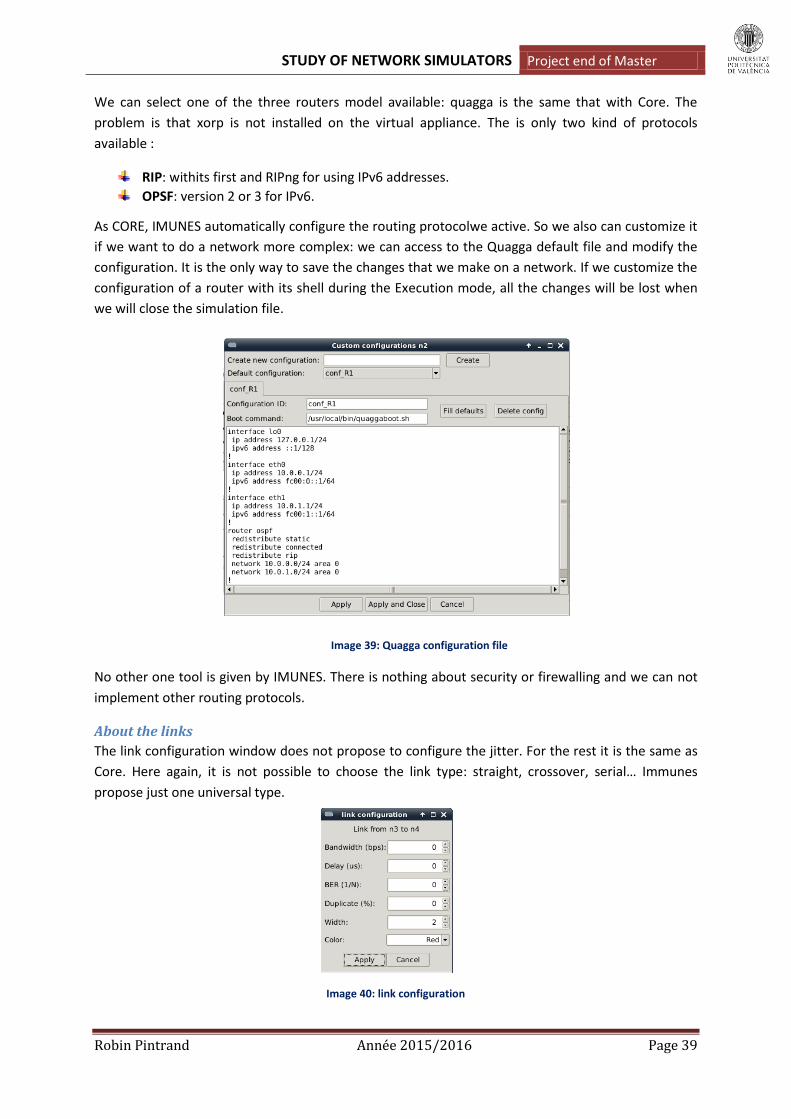
As CORE, IMUNES automatically configure the routing protocolwe active. So we also can customize it
if we want to do a network more complex: we can access to the Quagga default file and modify the
configuration. It is the only way to save the changes that we make on a network. If we customize the
configuration of a router with its shell during the Execution mode, all the changes will be lost when
we will close the simulation file.
Image 39: Quagga configuration file
No other one tool is given by IMUNES. There is nothing about security or firewalling and we can not
implement other routing protocols.
About the links
The link configuration window does not propose to configure the jitter. For the rest it is the same as
Core. Here again, it is not possible to choose the link type: straight, crossover, serial… Immunes
propose just one universal type.
Image 40: link configuration

STUDY OF NETWORK SIMULATORS Project end of Master
Robin Pintrand Année 2015/2016 Page 40
About the hosts
As said before they are just defined by their name and interface adresses. We can not activate
services as with Core. But, we can create files implementing a service: for example IMUNES proposes
a file to simulate the DHCP server action. The file has to be placed in the same folder where we have
created our simulation files. But, the big drawback compared with Core is that this file is usable only
for one specific example. Indeed, with Core the services are implemented and so configurable for
different example. Here it is more complicated, we create one file for one example. To well
understand, let’s see at this example:
Image 40: DHCP example
So here we have a DHCP server who has to give adresses to the computers FIX, PC1, PC2 and PC3. To
simulate this, we have to create a file wrote in Bash language: this file is personalized for our
example.
Image 41: DHCP Bash file configuration « start_dhcp »
1
2

STUDY OF NETWORK SIMULATORS Project end of Master
Robin Pintrand Année 2015/2016 Page 41
Here we can see the variables appropriated to our example: the name of our DHCP server and the
different hosts.
This part simulates the action of a DHCP server: it is write that for each client pass in argument (here
FIX, PC1, PC2), DHCPserver will give us an address in agreement with their network of membership.
So, when we start the emulation on IMUNES we also have to start this script using the shell
command «./start_dhcp » in the right folder. So we can see the action of our DHCP server:
Image 42: auto-configuration of the IP address
Now three clients are configurated but PC3 do not have address yet because it was not passed in
argument. To configure it we have to enter the command « dhclient eth0 » in its shell as wrote in the
previous script:
Image 43: PC3 DHCP configuration
To summarize we can say that IMUNES allows the user to create services but he does not propose
services pre-implemented as Core. The user has to create his own services, writting his own script in
Bash which is a way more complicated.
1
2
STUDY OF NETWORK SIMULATORS Project end of Master
Robin Pintrand Année 2015/2016 Page 42
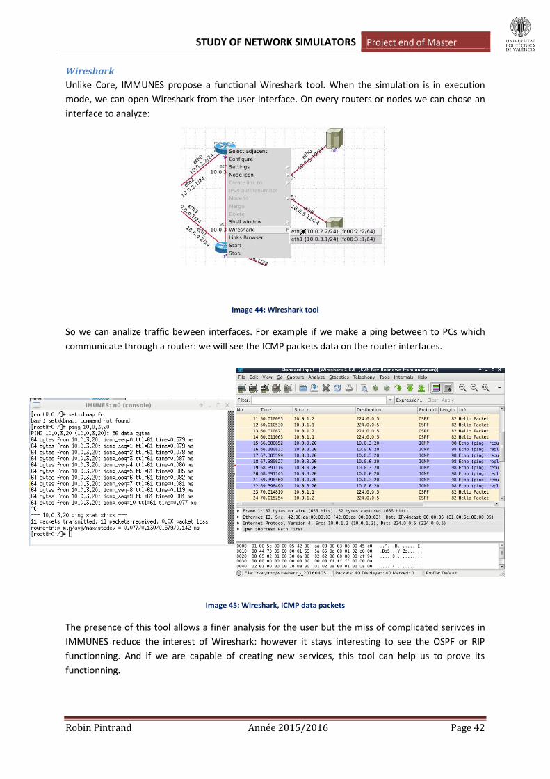
Wireshark
Unlike Core, IMMUNES propose a functional Wireshark tool. When the simulation is in execution
mode, we can open Wireshark from the user interface. On every routers or nodes we can chose an
interface to analyze:
Image 44: Wireshark tool
So we can analize traffic beween interfaces. For example if we make a ping between to PCs which
communicate through a router: we will see the ICMP packets data on the router interfaces.
Image 45: Wireshark, ICMP data packets
The presence of this tool allows a finer analysis for the user but the miss of complicated serivces in
IMMUNES reduce the interest of Wireshark: however it stays interesting to see the OSPF or RIP
functionning. And if we are capable of creating new services, this tool can help us to prove its
functionning.

STUDY OF NETWORK SIMULATORS Project end of Master
Robin Pintrand Année 2015/2016 Page 43
Examples of routing protocols
As said before, IMUNES propose only RIP and OSPF. So I’m going to show a big simultation network
mixing the two protocols: we can create quickly a lot of nodes but the poverty of services obliges us
to create a network with a basic functioning.
Image 46: OSPF-RIP example
So, here we have four areas: in each area the routers use RIP protocols. But between areas, routers
use OSPF. So R0, R1, R2 and R3 are the Area Border Gateway and manage the two protocols by
redistribuing the RIP route into OSPF for the other networks. By default, as with Core, all the
interfaces are in the same area so we have to customize the configuration of all the ABR as following:
Image 47: R0 configuration
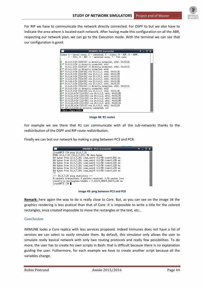
STUDY OF NETWORK SIMULATORS Project end of Master
Robin Pintrand Année 2015/2016 Page 44
For RIP we have to communicate the network directly connected. For OSPF to but we also have to
indicate the area where is located each network. After having made this configuration on all the ABR,
respecting our network plan, we can go to the Execution mode. With the terminal we can see that
our configuration is good:
Image 48: R1 routes
For example we see there that R1 can communicate with all the sub-networks thanks to the
redistribution of the OSPF and RIP route redistribution.
Finally we can test our network by making a ping between PC3 and PC8:
Image 49: ping between PC3 and PC8
Remark: here again the way to do is really close to Core. But, as you can see on the image 34 the
graphics rendering is less pratical than that of Core: it is impossible to write a title for the colored
rectangles, once created impossible to move the rectangles or the text, etc…
Conclusion
IMMUNE looks a Core replica with less services proposed. Indeed Immunes does not have a list of
services we can select to easily simulate them. By default, this simulator only allows the user to
simulate really basical network with only two routing protocols and really few possibilities. To do
more, the user has to create his own scripts in Bash: that is difficult because there is no explanation
guiding the user. Futhermore, for each example we have to create another script because all the
variables change.

STUDY OF NETWORK SIMULATORS Project end of Master
Robin Pintrand Année 2015/2016 Page 45
The graphics rendering looks older and less convenient. But in terms of performance, the exchange
of IP routes seems faster.
The real advantage of Immunes regard of Core is that the Wireshark tool works perfectly which allow
us to analyse the traffic more easily. The basic handling is also rather simple.
Finally, we can say that this simulator is less adapted than Core to great big networks and learn some
important services like IPsec, firewall rules, BGP, etc. It is more usable for small basical networks that
we want to analyze finely with Wireshark.
Marionnet
Marionnet is an open-source network simulator that creates a network composed of Linux virtual
machines. A group of educators at the Université Paris 13 created Marionnet. So their aim was to be
able to use MARIONNET in an educational purpose: Marionnet allows students to build and configure
networks, and save their configurations for future use. It also allows teachers to prepare exercises
and tests. All the softaware is written in french.
Contrary to the other emulators seen previously, the Marionnet work group does not propose a
virtual appliance directly usable by VirtualBox: we have to use a Linux machine and install Marionnet
by downloading the Marionnet’s script. The Marionnet network simulator is easy to install but there
are some specific system configurations that must be changed so that all the features of Marionnet
work well. I am not going to explain this configurations in details because it is not the aim of this
project ; But it is important to follow the tutorial on the website
http://www.brianlinkletter.com/install-the-marionnet-network-simulator-on-debian-linux-6-0/ to
install the simulator properly.
Overview
Once installed, we can run Marionnet by writting the command « marionnet.byte » in the computer
shell: Marionnet does not propose an icon tool on the desk as Core or Immunes.
Image 50: GUI of Marionnet
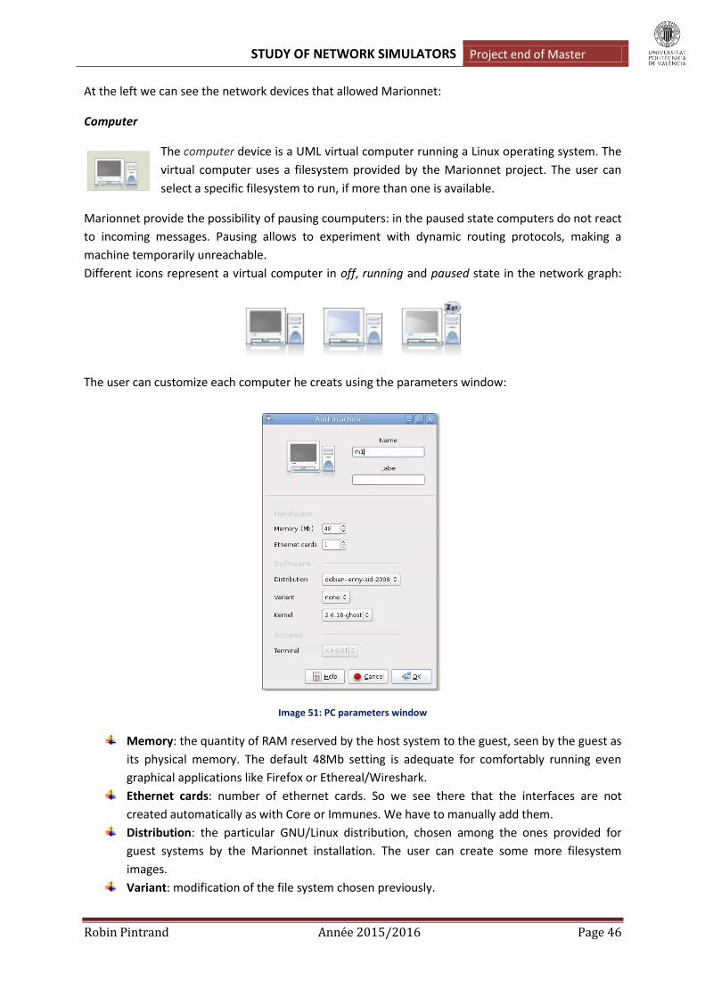
STUDY OF NETWORK SIMULATORS Project end of Master
Robin Pintrand Année 2015/2016 Page 46
At the left we can see the network devices that allowed Marionnet:
Computer
The computer device is a UML virtual computer running a Linux operating system. The
virtual computer uses a filesystem provided by the Marionnet project. The user can
select a specific filesystem to run, if more than one is available.
Marionnet provide the possibility of pausing coumputers: in the paused state computers do not react
to incoming messages. Pausing allows to experiment with dynamic routing protocols, making a
machine temporarily unreachable.
Different icons represent a virtual computer in off, running and paused state in the network graph:
The user can customize each computer he creats using the parameters window:
Image 51: PC parameters window
Memory: the quantity of RAM reserved by the host system to the guest, seen by the guest as
its physical memory. The default 48Mb setting is adequate for comfortably running even
graphical applications like Firefox or Ethereal/Wireshark.
Ethernet cards: number of ethernet cards. So we see there that the interfaces are not
created automatically as with Core or Immunes. We have to manually add them.
Distribution: the particular GNU/Linux distribution, chosen among the ones provided for
guest systems by the Marionnet installation. The user can create some more filesystem
images.
Variant: modification of the file system chosen previously.

STUDY OF NETWORK SIMULATORS Project end of Master
Robin Pintrand Année 2015/2016 Page 47
Kernel : Linux version kernel.
Terminal: type of terminal. The user can chose X HOST or Xnest. When a machine has its
terminal type set to host the user interacts with it in text mode using a simple virtual
terminal window, and can launch graphical applications which draw their clients on the same
X display where Marionnet runs. In Xnest mode, instead, a running virtual computer has a
window (shown on the host display, of course) representing its monitor and running some
graphical desktop system: the guest X clients are clearly separated from the host ones and
the ones belonging to other guests. This setting is particularly appropriate for beginners.
As we can see the customization is more realistic than that of the previous emulators.
Hub
Classic hub which reproduce the signal it receives from one of its port into all the other
ports. Each port are defined by :
A label: that can be a name to be shown on the network graph.
A number of Ethernet ports. (4 by default)
Notice that as all the devices, the hubs can be in off, paused or running state.
Switch
Classical switch defined by the same parameters as the hubs.
Image 52: Switch configuration window
Routers
With Marionnet the routers are defined with the window bellow:

STUDY OF NETWORK SIMULATORS Project end of Master
Robin Pintrand Année 2015/2016 Page 48
Image 53: Router configuration window
As we can see, we have to indicate the IP address of the port ET0 and the number of ports. It shows
well that the creation is not as flexible as that of Core or Imunes. The part Software is the same as for
the hosts because virtual routers are implemented with the Quagga software: so we can run the
services on UML virtual machine as the computers. The part called « Access » only allow opening the
UML virtual machine for the router when we start the emulation (Execution mode).
Cables
Marionnet allows the use of different kind of link: crossover or straight links. So this
simulator makes the difference between the MDI and MDIW ports. So, to create correct
networks we have to be careful abour what kind of links we use: the simulation will not
run if the nodes are not connected with the right links.
Image 54: Type of ports following nodes type
But, we can not customize a lot the links: the configuration window just allows to chose a name and
especially she obliges us to choose both extremities.

STUDY OF NETWORK SIMULATORS Project end of Master
Robin Pintrand Année 2015/2016 Page 49
Image 55: Link configuration window
Virtual ethernet Cloud
A cloud represents an Ethernet network composed of hubs, switches and cables, with
exactly two endpoints an unspecified internal structure. The only externally observable
effects of a cloud consist in delays and other anomalies in the relaying of frames from
one endpoint to the other. The cloud definition dialog is not particularly interesting, as it only allows
setting a name and an optional label to be shown in the network graph.
Virtual external socket
The external socket device represents a “female Ethernet wall socket”, opening a
breach in this apparent closure: when connected to an external socket other
components can access the same (non-virtual) network to which the host belongs.
External sockets provide several useful opportunities:
Connecting virtual computers to the Internet.
Easily installing additional software on virtual machines, for example using apt-get install on
a debian distribution.
Making virtual computers clients of services offered by the host or its network: some
examples include DHCP, DNS, NFS, and NTP.
It is also possible to use external sockets to connect several virtual networks, possibly running on
different hosts. The implementation depends on the bridging functionality in Linux.
The configuration window only allows use to chose a name for the socket.
As said before the network creation is really more static than previous tested simulators: the IP
address is not generated automatically, we can not move the nodes created, the links are creating by
configuring the extremities, etc. All this makes that the creation of network is appreciably longer: we
already can say that this simulator is not adapted to simulate big network, with dozen of routers,
switchs… To illustrate this, we can see bellow a network with only 3 routers, 3 switchs and 3
computers:

STUDY OF NETWORK SIMULATORS Project end of Master
Robin Pintrand Année 2015/2016 Page 50
Image 56: the lack of space of Marionnet
As we see, it is not a big network but the simulator already has difficulty in revealing him completely
on the screen. We have well some tools on the right which allow twist the links or reduce the nodes
size but it is not enough. The fact that we can not customize our network with colors and geometrical
forms also complicate the virtual rendering: we do not see well the different networks, the IP
address, the interfaces…
Clearly, in terms of capacity, this simulator seems more oriented towards small networks.
Features and characteristics
Configuration menus
To compensate for the lack of customization in the configuration of these nodes, Marionnet
proposes four menus which allow controlling and managing better our network: these menus can
bee seen at the bottom of the image 44.
Menu Image: it is the menu where we can see the network created. I have already seen that
is not rezlly convenient.
Menu Interfaces: here we can configurate all the nodes interfaces created in our network.
For each node, we see the interfaces created. So we can configurate their IPv4 and IPv6
address, the MTU, the broadcast address and their mask.

STUDY OF NETWORK SIMULATORS Project end of Master
Robin Pintrand Année 2015/2016 Page 51
Image 57 : Interfaces menu
Menu Anomalies (Defects): this menu proposes to simulate several kind of faulty behaviour.
Image 58: Anomalies menu
For each nodes and links we can add defects to analize the consequences on the networks:
percentages of frames lost, frames duplicated, bits inversed, delay minimal and maximal.
Menu Disques (Filesystem history): For each virtual computer or router, a complete history
of the disk states is available: each state is saved just before startup. This state is so the

STUDY OF NETWORK SIMULATORS Project end of Master
Robin Pintrand Année 2015/2016 Page 52
configuration before we pass in the Execution Mode and so take in account the configuration
in the previous menus. The entire configuration did during the simulation will not be saved.
A machine or router can be started up in the most recent state (which is the default
behavior), or in any previously saved state. This allows users to freely experiment with
potentially “dangerous” filesystem modifications, as each change is reversible. For each
machine or router the filesystem history displays a tree structure keeping track of the
“parent-child”derivation relation of states. States can also be deleted or exported as variants,
to be used for new machines or routers in the same or even in different projects. Indeed, we
have seen that the configuration of a network is quite long: so it could be interesting to
export configuration files of routers and computers to do not have to configurate their
interfaces at each time.
Image 59: Filesystem history
Protocols and routing
The software Quagga used by Marionnet allows the following routing protocols: RIP, OSPF, IS-IS and
OSFP. But the maneer to use them is different of Core or Immunes: there are no services which
implement directly the protocols. So we have to pass in Execution MODE and configurate them on a
terminal as if we where on a real router. To open a router shell we just have to write the command
« vtysh » in its UML virtual machine which is launched when the emulation begin.
This approach has its advantages and its disadvantages: Marionnet force us to configurate manually
all the protocols we want to use. We can not just activate OSPF on a router by clicking on the option
tool as Core. So it is a good thing to learn how to configurate each protocols. But, as we have to
configure all, it is a way longer: it confirms our previous conclusions which said that this simulator
can not be use to simulate big network. The work would be too fastidious and long.

STUDY OF NETWORK SIMULATORS Project end of Master
Robin Pintrand Année 2015/2016 Page 53
The last things that demonstrate well that Marionnet have not been created to simulate complex
networks is that: when we pass in the Execution Mode one terminal for each node open. So the
screen is quickly overloaded and it is impossible to see your network and the different terminals at
the same time.
Image 60: Overloaded Marionnet screen
IS-IS implementation:
Because of this we can not show a great example of network using IS-IS and BGP. But, I’m going to
show a little example that show that IS-IS is usable with this simulator:
Image 61: Exemple of network using IS-IS protocol
To activate the IS-IS protocol we have to configure it on R1 and R2. The configuraiton works with the
Cisco commands once we are in the vtysh shell. For each interface we have to indicate the network
reachable and activate IS-IS. More generally, we need to chose a number of area and creat our net
address to identificate our router. We also have to add the default gateway on PC1 and PC2: it is
really the same manipulation that in a physical case.

STUDY OF NETWORK SIMULATORS Project end of Master
Robin Pintrand Année 2015/2016 Page 54
Image 62: IS-IS lines configuration
After we can use the many included network-aware commands to analize the routing tables and
make sure that the protocol is well implemented.
Image 63: IS-IS route
We can see that the foreign routes are well learnt by the routers thanks to the IS-IS router.
Marionnet allows the IS-IS commands as « shwo clns » to have more informations about the
implementation.
Finally, we can test the communication from start to finish by trying a ping between PC1 and PC2.
Image 64: Ping between PC1 and PC2

STUDY OF NETWORK SIMULATORS Project end of Master
Robin Pintrand Année 2015/2016 Page 55
Test of network using BGP and IS-IS
Even if it is impossible to create big network, I tried to create a network that use at the same time
BGP and ISIS. The network created looked like:
Image 65: Example using BGP and IS-IS
Here we have three network using IS-IS: R1, R2 and R3. But R4 only use the BGP protocol: so R1 have
to implement also BGP if we want make possible the ping between PC1 and PC3 for example. So after
configuration the network part using IS-IS we can configurate BGP on R1 and R4. At this moment we
can see that R1 know all the routes:
Image 66: Routing table of R1
On the image 54 we well see that R1 is the central router and learn the routes IS-IS and BGP. But, the
problem is that is impossible to configurate the BGP routes redistribution on the Marionet router
when we use IS-IS: we can use the command « redistribute bgp metric 100 » only if we use OSPF or
RIP as IGP protocol. So, R2 and R3 can not discover the network 192.168.6.0/24 by using IS-IS:

STUDY OF NETWORK SIMULATORS Project end of Master
Robin Pintrand Année 2015/2016 Page 56
Image 67: Routing table of R2
Without the routes redistribution, we see that R2 only learn the routes included in the network IS-IS.
To access to the network 192.168.6.0/24 we should add a default or static route towards R1, but the
learning will not be dynamic…
Image 68: Ping after creation of a static route
So Marionnet is closed to offer us the possibility to create a network mixing BGP and IS-IS, just one
command remain to have a full dynamical configuration.
Security
Immunes use a Quagga version which not allows the NAT commands. But, in the UML machine
terminal it is possible to use the command iptables which allow some possibilties:
Here it is an exemple of Network needing some security rules. Indeed we can see two inside
networks (10.0.1.0/24 and 10.0.2.0/24) which have to communicate with an external network,
potentially dangerous, 192.168.10.0/24.
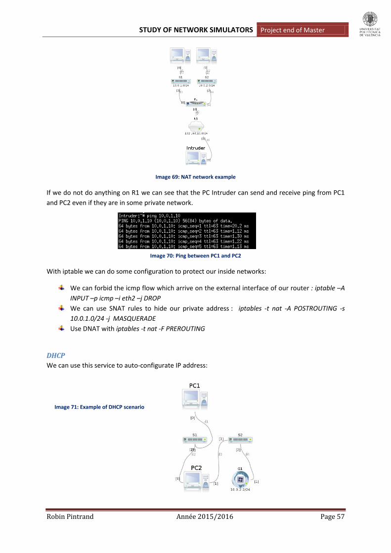
STUDY OF NETWORK SIMULATORS Project end of Master
Robin Pintrand Année 2015/2016 Page 57
Image 69: NAT network example
If we do not do anything on R1 we can see that the PC Intruder can send and receive ping from PC1
and PC2 even if they are in some private network.
Image 70: Ping between PC1 and PC2
With iptable we can do some configuration to protect our inside networks:
We can forbid the icmp flow which arrive on the external interface of our router : iptable –A
INPUT –p icmp –i eth2 –j DROP
We can use SNAT rules to hide our private address : iptables -t nat -A POSTROUTING -s
10.0.1.0/24 -j MASQUERADE
Use DNAT with iptables -t nat -F PREROUTING
DHCP
We can use this service to auto-configurate IP address:
Image 71: Example of DHCP scenario

STUDY OF NETWORK SIMULATORS Project end of Master
Robin Pintrand Année 2015/2016 Page 58
Here we want to auto configurate the interface ETH1 of PC2. To do this we just have to use the
following commad in the PC2 terminal: « dhclient eth1»
Image 72: DHCP request
So, thanks to this command, PC2 listens on its ETH1 interface to find a DHCP provider. Finding the
virtual external gateway, he asks for an IP address: we see that the gateway gives the address
10.0.2.15 to him.
The VDE switch terminal
Marionnet propose a tool that was not implemented in the previous simulator: its switchs can be
customized. Indeed, Marionnet propose a switch terminal that is open when we pass in the
Execution mode. This terminal allows two switch functionnalities:
The VLAN creation :
To explain this, let is take an example:
Image 73: VLAN network example
So here we have four PCs, in the same network 192.168.10.0/24, connected to the switch S1. By
default, it is possible to do ping and receive data between all the PCs as shwon by the image below:
Image 74: ARP cache of PC1
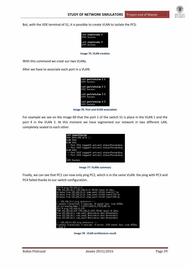
STUDY OF NETWORK SIMULATORS Project end of Master
Robin Pintrand Année 2015/2016 Page 59
But, with the VDE terminal of S1, it is possible to create VLAN to isolate the PCS:
Image 75: VLAN creation
With this command we creat our two VLANs.
After we have to associate each port in a VLAN:
Image 76: Port and VLAN association
For example we see on the image 60 that the port 1 of the switch S1 is place in the VLAN 1 and the
port 4 in the VLAN 2. At this moment we have segmented our network in two different LAN,
completely sealed to each other.
Image 77: VLANs summary
Finally, we can see that PC1 can now only ping PC2, which is in the same VLAN: the ping with PC3 and
PC4 failed thanks to our switch configuration.
Image 78 : VLAN architecture result

STUDY OF NETWORK SIMULATORS Project end of Master
Robin Pintrand Année 2015/2016 Page 60
Fast Spanning Tree Protocol :
This functionnality is usable by activating it in the VDE shell. We just have to write the command:
« fstp/setfstp 1 » (0 to disactivate). Once FSTP is activated we can creat network with loops without
problem.
Image 79: Network using the FSTP protocol
Here the ping between PC1 and PC2 is possible thanks to the FSTP action.
Deepening and notice
Wireshark
All the Machine devices have the Wireshark packet analyzer application installed. When you run
wireshark on any machine, the GUI appears on the host computer’s desktop. To start Wireshark on
machine we just have to write « wireshark & » on its terminal.
Image 80: Wireshark Marionnet
STUDY OF NETWORK SIMULATORS Project end of Master
Robin Pintrand Année 2015/2016 Page 61
IPV6
In the menu « Interface » explained previously we can assign IPv6 to every interface. So Marionnet
perfectly allow the creation of network using IPv6. But we have to be careful about the routing
protocol we are implementing: all of them are not usable with IPv6.
Performances of the Marionnet virtual machine
As said before, Marionnet have to open all the devices terminal creat in our network each time we
pass in the Execution mode. So it takes quiet a long time to run all the programs executed in
background. The good thing is that it is possible to shudown only one device to modificate it: this is
not necessary to shutdown all the network. When the device is runned again the network actualizes
itself quickly.
Marionnet use a lot of space: more than 8Go without example saved. So the user has to be careful
when he creats his VM to use Marionnet.
The biggest drawback of Marionnet in terms of performance is its backup system: we can not save
the entire configuration that we have done on the terminals of our different PC, routers or switch.
We can only save the configuration before the Execution mode which consists only in the interfaces
configuration and some defects if we want to. But, as we can not customize the devices directly in
their configuration files as it was possible with Core or Immunes: we lose the entire configuration
each time we leave Marionnet software.
Conclusion
This simulator offer some functionnalities which was not present in the two previous one: IS-IS
protocol, Switch terminal… But it suffers from the fact that its GUI is not convenient. The network
creation are far longer and static, the graphical rendering is also rather poor.
The fact that is all the configurations are done since the terminal allows the user to better learn the
configuration of network protocol in small architecture. Marionnet thus seems to have a more
educational character.
In terms of funcionality, we will regret the fact it is not possible to redistribute the BGP route in IS-IS.
But, when holding it and using the different menus, Marionet offer a powerful interface to test case
with trafic issues, packets lost, disconnected cable…
The problem of its backup system remain the negative point because it does not allow the backup of
examples enterely configurated and force the user to do again the same commands each time he
open a file.

STUDY OF NETWORK SIMULATORS Project end of Master
Robin Pintrand Année 2015/2016 Page 62
GNS3
GNS3 is a graphical network simulator which presents a feature that did not possess the previous
simulator: it allows the user to emulate Cisco IOS, so it is also an emulator. It significates that you can
download a real image of Cisco router and fully use it on a computer. That is why this simulator is
used a lot to prepare himself to Cisco certifications.
GNS3 can be installed on Windows, Linux or Mac devices. That is why I directly downloaded the
software on the GNS3 website on my Windows partition. During the installation, GNS3 install some
impotant tools :
Winpcap: this dependency is required for GNS3 to communicate with real networks through
a physical network internal controller.
Dynamips: will allow the user to download and emulate IOS router images.
Quemu: this tool will allow the user to download and emulate VMs.
Wireshark: this tool is integrated by default and will allow us to analyze the traffic on the
different interfaces.
Solar Winds: another tool to analyze the response time, based on the Wireshark capture.
In terms of volume, GNS3 basic installation only uses about 300 Mo, but we have to save some free
space for the futur network tests.
Overview
To run GNS3 on Windows, a double click on the icon tool is enough:
Image 81: GUI of GNS3
So we arrive on the same type of GUI as the previous simulators. On the right we find the different
network devices usable with GNS3:
The routers: that is really important to say that GNS3 does not provide IOS of router by
default. We have to find Cisco router image on the internet. It is a little bit less convenient
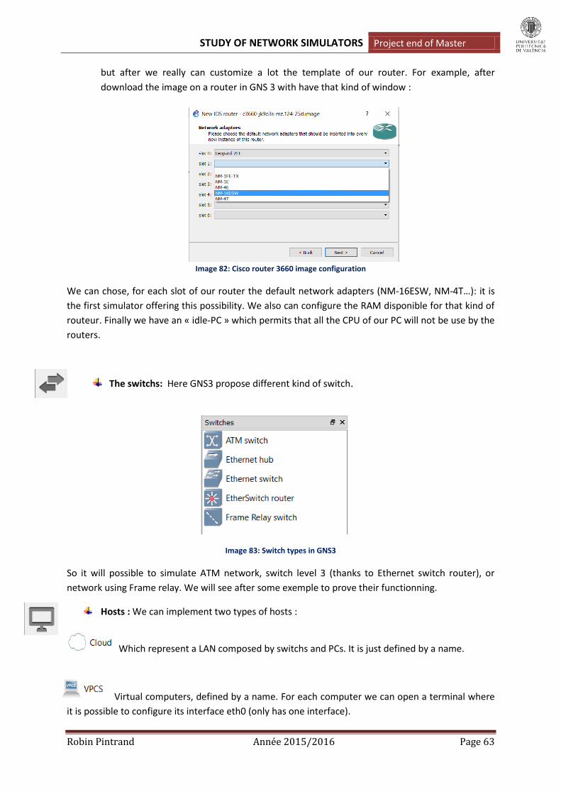
STUDY OF NETWORK SIMULATORS Project end of Master
Robin Pintrand Année 2015/2016 Page 63
but after we really can customize a lot the template of our router. For example, after
download the image on a router in GNS 3 with have that kind of window :
Image 82: Cisco router 3660 image configuration
We can chose, for each slot of our router the default network adapters (NM-16ESW, NM-4T…): it is
the first simulator offering this possibility. We also can configure the RAM disponible for that kind of
routeur. Finally we have an « idle-PC » which permits that all the CPU of our PC will not be use by the
routers.
The switchs: Here GNS3 propose different kind of switch.
Image 83: Switch types in GNS3
So it will possible to simulate ATM network, switch level 3 (thanks to Ethernet switch router), or
network using Frame relay. We will see after some exemple to prove their functionning.
Hosts : We can implement two types of hosts :
Which represent a LAN composed by switchs and PCs. It is just defined by a name.
Virtual computers, defined by a name. For each computer we can open a terminal where
it is possible to configure its interface eth0 (only has one interface).
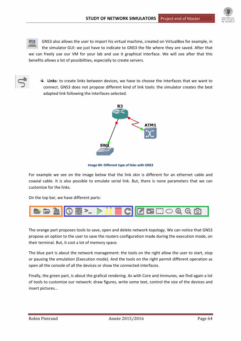
STUDY OF NETWORK SIMULATORS Project end of Master
Robin Pintrand Année 2015/2016 Page 64
GNS3 also allows the user to import his virtual machine, created on VirtualBox for example, in
the simulator GUI: we just have to indicate to GNS3 the file where they are saved. After that
we can freely use our VM for your lab and use it graphical interface. We will see after that this
benefits allows a lot of possibilities, especially to create servers.
Links: to create links between devices, we have to choose the interfaces that we want to
connect. GNS3 does not propose different kind of link tools: the simulator creates the best
adapted link following the interfaces selected.
Image 84: Different type of links with GNS3
For example we see on the image below that the link skin is different for an ethernet cable and
coaxial cable. It is also possible to emulate serial link. But, there is none parameters that we can
customize for the links.
On the top bar, we have different parts:
The orange part proposes tools to save, open and delete network topology. We can notice that GNS3
propose an option to the user to save the routers configuration made during the execution mode, on
their terminal. But, it cost a lot of memory space.
The blue part is about the network management: the tools on the right allow the user to start, stop
or pausing the emulation (Execution mode). And the tools on the right permit different operation as
open all the console of all the devices or show the connected interfaces.
Finally, the green part, is about the grafical rendering. As with Core and Immunes, we find again a lot
of tools to customize our network: draw figures, write some text, control the size of the devices and
insert pictures…

STUDY OF NETWORK SIMULATORS Project end of Master
Robin Pintrand Année 2015/2016 Page 65
Image 85: example of network customization
On the right of the GUI we have two windows:
The topology summary: we find here all our devices. If they are connected they are in green
and if not, they are in red. That is allowing the user to quickly repere a mistake in big
topology.
Server’s summary: show the part of our PC’s CPU used by the opened project.
On the center of the GUI we have the place to create networks. We can pass GNS3 in full screnn and
also reduce the size of the other window: so it is really possible to create big topology in terms of
space. But, as shown in the Overview, there are really few possible configurations in the Edition
Mode.
Features and characteristics
The configuration in Edition Mode
As Marionnet, we can not configure IP adresses directly on the configuration windows of our devices.
Moreover, it is also impossible to activate services as routing protocols as it was possible on Core and
Immunes. The biggest part of the configuration has to be done in the Execution mode. The
configuration type in Edition Mode is more oriented towards hardware. As shown before, we can use
the slot type for our routers: following the type of network we want to create we will have to choose
the right type of interface. For all the devices using an IOS it is possible to customize the RAM and the
images emulated.
At the OSI level 2, it is also possible to create ports on the different type of switchs and easily create
VLANs:

STUDY OF NETWORK SIMULATORS Project end of Master
Robin Pintrand Année 2015/2016 Page 66
Image 86: VLAN creation thanks to GNS3
As we can see on the image 73, we just have to select a port to assignated it a VLAN tag: here ports
connecting PC3 and PC4 (port 1 and 2) are placed in VLAN 1 and the ports connecting PC1 and PC2
(port 3 and 4) are place in VLAN 2.
The isolation of the two VLAN perfectly works as we can see with a test ping on PC1:
Image 87: VLAN results
We also can configurate our switchs and routers to create network using: ATM and Frame Relay. It is
the first simulator to porpose adapted switchs for that kind of networks.
ATM:
Asynchronous Transfert Mode is a protocol which allows to transfert at the same time data and voice
on a same link.
The ATM was finalized by the CNET. Contrary to the synchronous networks (as phone networks)
Where the data are emittedin a synchronous way that is the bandwidth is distributed (multiplexed)
between the users according to a temporal division, the ATM network transfer the data in a
asynchronous way, what mean that it transmits as soon as he can. Then that the synchronous
networks emit nothing when a user has to emit nothing, the network ATM is going to use these
whites to transmit other data, so guaranteeing a better bandwidth!

STUDY OF NETWORK SIMULATORS Project end of Master
Robin Pintrand Année 2015/2016 Page 67
ATM is « connexion » oriented: each connexion is tag with a VCI (Virtual Channel Identifier) and a VPI
(Virtual Path Identifier). GNS3 permit to easy configure this couple thanks to the configuration
window of the ATM switch:
Image 88: ATM switch configuration thanks to GNS3
But the ATM configuration on the routers has to be done in Execution Mode. We will see after an
example of ATM network.
Frame Relay:
This packet switching protocol works at the layer 2 of the OSI model. It is used for the intersites
exchanges (WAN) because it is economical.
Within the cloud Frame Relay, the connection between two sites is made through virtual circuits
which can be hard established there by the supplier, in this case, they are permanent and we speak
about Permanent Virtual Circuit (PVC). They can be also established only on request and we speak
about Switched Virtual Circuit (SVC).
PVC becomes identified at the level of the ATM switchs thanks to DLCI (Data Link Connection
Identifiers) to be able to distinguish resulting flows to various PVC. The DLCI is generally numbers of
identification with only local value (on an interface) which we assimilate to a sub-interface in certain
contexts: on a routerfor example, every PVC of an interface can so have its own associated IP
address.
GNS3 allows to configurate the DLCI in a graphical way on the configuration window of the ATM
switchs:
Image 89: Frame Relay switch configuration
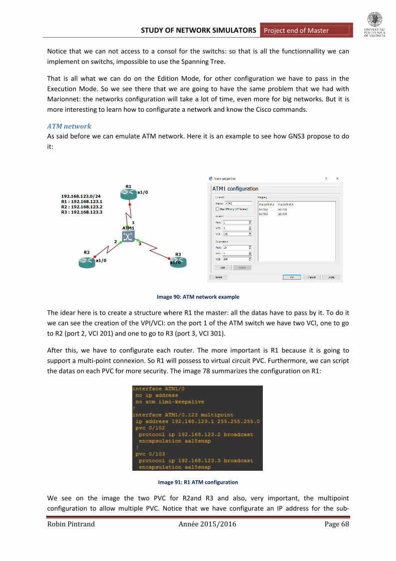
STUDY OF NETWORK SIMULATORS Project end of Master
Robin Pintrand Année 2015/2016 Page 68
Notice that we can not access to a consol for the switchs: so that is all the functionnallity we can
implement on switchs, impossible to use the Spanning Tree.
That is all what we can do on the Edition Mode, for other configuration we have to pass in the
Execution Mode. So we see there that we are going to have the same problem that we had with
Marionnet: the networks configuration will take a lot of time, even more for big networks. But it is
more interesting to learn how to configurate a network and know the Cisco commands.
ATM network
As said before we can emulate ATM network. Here it is an example to see how GNS3 propose to do
it:
Image 90: ATM network example
The idear here is to create a structure where R1 the master: all the datas have to pass by it. To do it
we can see the creation of the VPI/VCI: on the port 1 of the ATM switch we have two VCI, one to go
to R2 (port 2, VCI 201) and one to go to R3 (port 3, VCI 301).
After this, we have to configurate each router. The more important is R1 because it is going to
support a multi-point connexion. So R1 will possess to virtual circuit PVC. Furthermore, we can script
the datas on each PVC for more security. The image 78 summarizes the configuration on R1:
Image 91: R1 ATM configuration
We see on the image the two PVC for R2and R3 and also, very important, the multipoint
configuration to allow multiple PVC. Notice that we have configurate an IP address for the sub-

STUDY OF NETWORK SIMULATORS Project end of Master
Robin Pintrand Année 2015/2016 Page 69
interface ATM1/0.123: it means that it is possible to have more sub-interfaces and so multiple IP
addresses on one physical interface (ATM 1/0).
On the other routers, we have to configurate point to point interface because the only can
communicate with R1:
Image 92: R2 ATM configuration
For exemple we see on R2 we also have to give an address to the sub-interface and activate the
encryption.
Finally we can see our configuration is working well by testing two traceroute on R3: one towards R1
and another towards R2.
Image 93: Traceroute from R3 to R1 and R2
We see on the image 80 that we succeed because R3 has to pass by R1 to join R2.
Remarks: To create ATM network, we have to donwload a router image which allows us to use ATM
interface
So we can say that GNS3 simplify the creation of ATM network thanks to the configuration window
on the ATM switchs. Moreover, with the Cisco router image that we can download, we have access
at all the needed command to configurate the routers interfaces.
Frame relay (FR) network
Here we will show an example of Frame Relay cloud to show how GNS3 allows the user to implement
it.

STUDY OF NETWORK SIMULATORS Project end of Master
Robin Pintrand Année 2015/2016 Page 70
Image 94: Example of Frame Relay network
Thanks to the configuration window that proposes GNS3 on the FR switchs, we can easily pre-
configurate the required DLCI. We just have to be very careful to respect the FR rules. For example,
between two switchs, we have to use the same DLCI. Moreover, each connection has to use a
different DLCI, etc.
Image 95: DLCI configuration
To complete the configuration we just have to activate the Frame Relay encapsulation on each router
and assignate an IP address on the serial interfaces:
Image 96: Frame Relay configuration on routers
After this our network is working, as shown by the image 84:
Image 97: Traceroute from R2

STUDY OF NETWORK SIMULATORS Project end of Master
Robin Pintrand Année 2015/2016 Page 71
Remarks: before the latest GNS3 version (1.4), it was not possible to connect Frame Relay switchs
together.
Security
As GNS3 allows us to use Cisco router images, we have access at all the command which permit to
secure our networks: ipsec, iptables, crypto map…
It is not the main purpose of our project, but I’m going to show an example to well see that we can
create secured connection between two networks:
Image 98: IPsec VPN example
Here we want to secure the communication between two private networks (10.10.10.0/24 and
172.16.10.0/24) throw a public network (20.20.20.0/24). GNS3 allows us to do it by doing the
following commands:
Image 99: Security configuration on R1
Here we have the 5 steps which allow securing a connexion:

STUDY OF NETWORK SIMULATORS Project end of Master
Robin Pintrand Année 2015/2016 Page 72
Create a crypto isakmp policy: here our policy takes the number 1. After we have to chose
the authentication method: here we chose the pre-share method. Pre-shared means the
parties must agree on a shared, secret key that becomes part of the IPSec policy. During
security negotiation, information is encrypted before transmission using the shared key, and
decrypted on the receiving end using the same key. If the receiver can decrypt the
information, identities are considered authenticated. Finally we create the key that will be
use to crypt the communication between our two networks. The image 86 is the R1
configuration so we indicate that the key have to be share with the interface S0 of R2
(20.20.20.2). That is the interface to join if we want to communicate with the network
172.16.10.0. The name of our key is « CISCO ».
We activate ipsec by creating a transform-set: A transform set combines an encryption
method and an authentication method. During the IPsec security association negotiation
with ISAKMP, the peers agree to use a particular transform set to protect a particular data
flow. The transform set must be the same for both peers. A transform set protects the data
flows for the access list specified in the associated crypto map entry. Here, our transform-set
is named myset and use the esp-aes encryption method and esp-sha-hmac authentication
method.
Now we create the access list which allows the communication between our two private
networks. This traffic will be encrypted thanks to the transform-set.
The creation of the crypto-map: it will summarize all the configuration made before and
allows us to applicate them to an interface. Here our crypto-map is named R1-R2. We
indicate the other side of the VPN tunnel (20.20.20.2) and we say that this crypto-map will
use the transform-set « myset » and the access-list « 101 ».
Finally we just have to assignate our crypto-map to the good interface: here the entry of the
VPN tunnel is the interface serial 0 of R1. The assignation is done by writtin the following
command on the interface: « crypto map R1-R2 ».
Once the configuration realized on the other interface (R2’s serial 0), we can check that the tunnel
was well set up. Indeed, GNS3 allows the use of all the managing commands. For example we can see
that our crypto session is up with the command « show crypto session ».
Image 100: show crypto session command
We also can chack that ipsec is well implemented between R1 and R2:
Image 101: show crypto isakmp sa command

STUDY OF NETWORK SIMULATORS Project end of Master
Robin Pintrand Année 2015/2016 Page 73
So we can see with this exemple that GNS3 allows all the possibilities provided by Cisco routers,
including in security.
We do not propose an example here but, in GNS3, we also can implement firewall rules thnaks to the
commands « iptables ».
Hosts
As we have said before, GNS3 allows the user to download image of Cisco routers and Pcs. Thanks to
that, it is possible to emulate the functionning of several servers:
DHCP: we have to configurate it on a router with the command the « ip dhcp server» which
allows the activation of this service.
FTP: it is possible to install the Internet Informations Services (IIS) package on the virtual PCs.
In this package we find the FTP server service. So we can configurate our virtual PCs as FTP
server. After that, for example, we can save the router configurations on a virtual PC: we just
have to be care to the space we have free on our physical computer.
HTTP: the command « ip http server » enabled on the Cisco router router make possible to
configure this type of server.
Protocols and routing
GNS3 propose to use Cisco image routers so it is possible to configurate the four networks that was
studied in this project: RIP, OSPF, IS-IS and BGP. As said before, all the router configuration is done in
the router console: that is not possible to access to the configuration file as Core or Marionnet. So
the manipulation to configurate all this protocols is more realistic but also take more time. Here we
are proposing two examples to validate the fact that GNS3 is a simulator/emulator which answers to
our expectations: one using IS-IS and BGP and another using the four routing protocols at the same
time.
Example with IS-IS and BGP:
Image 102: IS-IS & BGP example on GNS3

STUDY OF NETWORK SIMULATORS Project end of Master
Robin Pintrand Année 2015/2016 Page 74
In this example the goal is to do a ping between PC1 and PC2. To do it the ICMP request have to pass
accross two IS-IS area connected by public network using the BGP routing protocol. So we see on the
image 89 that R3 and R4 have to support IS-IS and BGP, the others only need to implement IS-IS. To
learn all the routes, the routers contained in the BGP areas need the fact that R3 and R4 redistibute
the BGP routes in IS-IS : remember that was the problem which occured with the Marionnet
simulator. Here the redistribute command works perfectly. To see the configuration, let’s see the
router R3 :
Image 103: R3 configuration
As we can see, BGP and IS-IS routing are implemented: IS-IS is activated on the interfaces intra-AS
and BGP is well redistributed. Notice that for all the routers execpt R3 and R4, we only implement IS-
IS without take in account the fact that it had a BGP link between the two areas IS-IS.
Once the configuration done, we can see that all the routes are well learnt by each router: the router
intra-AS thinks that they learn all the routes thanks to IS-IS but we see that some routes are really
learnt tahnks to BGP on the AS border routers:
Image 104: Routes learnt on an internal router

STUDY OF NETWORK SIMULATORS Project end of Master
Robin Pintrand Année 2015/2016 Page 75
Image 105: Routes learnt on a border router
Finally, we can try a ping between PC1 and PC2 to validate our global configuration:
Image 106: ping between PC1 and PC2
Global example:
Image 107: Global exemple

STUDY OF NETWORK SIMULATORS Project end of Master
Robin Pintrand Année 2015/2016 Page 76
Here we have an EGP ring composed by the routers R1, R2, R3 and R4: this four routers use so BGP.
In the AS 100, the IGP is OSPF with 2 areas. In the AS 200, we implement IS-IS as IGP. In the AS 300
and 400, the RIP protocol is used. So the four routers using BGP have to manage also an IGP and so,
have to redistribute the BGP route in OSPF, IS-IS or RIP. GNS3 allows us to create that kind of
network but the configuration time is a way more important that it was with Core, because we have
to do all on the nodes consol.
On each router with have to configurate:
The addresses and masks.
Activate the chosen routing protocol: declare the networks that the router has to
communicate to the others. In the IS-IS case, we also have to activate the protocol on each
interface using it. For BGP and OSPF, we have to be careful to place the routers in the good
areas and well configure the border gateway. Finally, we have to activate the BGP
redistribution on each interface using an IGP routing protocol on the BGP router. Thanks to
that, all the routes will be reachable.
For example, that is the confguration for R1, R2 and R3:
Image 108: Routing configuration for R1, R2 and R3
As you can see, it is exaclty the Cisco syntax. So, even if it is quite long, if we are meticulous, all will
works perfectly. After the configuration did on all the routers and the default gateway assignate for
each PCs we can see that all the route are communicated between routers:

STUDY OF NETWORK SIMULATORS Project end of Master
Robin Pintrand Année 2015/2016 Page 77
Image 109: Routes learnt on R1 on R9
As always : on the internal router all the routes are learnt thanks to the IGP protocol (BGP
redistribution) but on the BGP router we see that BGP well did its work to.
Finally we can try some pings between PCS to check our topology is completely correct:
Image 110: Ping between P4 and PC1, PC4 and PC2
Deepening and Notice
Wireshark
GNS3 propose the Wireshark tool. The way to use it is quite different from the previous simulators:
to open it we have to click on the links between to interfaces.
Image 111: Wireshark in GNS3
So the Wireshark window which opened is directly launched and captures the trafic between the
proper interfaces.

STUDY OF NETWORK SIMULATORS Project end of Master
Robin Pintrand Année 2015/2016 Page 78
IPv6 address
As the Cisco routers allow the use of IPv6 addresses, it is possible to create topology using that kind
of addresses. But we have to be careful: the virtual computers porposed by default do not support
IPv6 addresses. So, if we want to use host, we have to import a VM from VirtualBox and manually
assignated it an IPv6 address. Furthermore, we can not implement all the routing protocols with
IPv6: for example RIP does not support it.
Performances and ergonomics of GNS3 GNS3 is really easy to install cause we juste have to download a file on its web site to use it on all
kind of platform: Windows, Linux, MAC… The handling is rather simple when we have understood
that we had to download our own router image to use it. This possibility gives to GNS3 a powerful
configuration experience: indeed, with Cisco router images, we can emulate all kind of networks.
GNS3 doesn not propose services which auto-configurate IP addresses when we create a node. It also
does not provide an access to the node’s configuration files. So, all the configurations have to be
made on the consol and so it is really not quick, even more for the big networks. But it is a good way
to learn all the Cisco commands and how configurate a real network.
In terms of performance, the virtual nodes react quickly: they start in few second and the routes are
diffused really quickly, more than Core or Marionnet.
GNS3 allows the user to save his configuration did on consol but it cost a lot of memory: it is
important to prepare your computer before. But GNS3 is not lying about the funcionnalities
proposed because all of them works well.
Conclusion
Thanks to the Cisco images, GNS3 is surely the most powerful simulator we have test until now. We
have been able to create networks using all the routing protocols we wanted without issues and the
GUI is perfectly adapted for the creation of big networks.
GNS3 offers all the Cisco routers possibility but also provide some interesting switchs: the ATM and
Frame relay switchs permit to creat other kind of network which was no implementable with the
previous simulator.
We will just regret two things: the impossibility to manage switchs by consol (no spanning Tree) and
to create hosts directly implemented by the simulator to emulate some server functionnality: DNS,
http…

STUDY OF NETWORK SIMULATORS Project end of Master
Robin Pintrand Année 2015/2016 Page 79
Cloonix
Cloonix is a network simulator which uses KVM to create Virtual Machine. This simulator is quite
different to the others simulators analized before because of its GUI. It is not intuitive at all and it
does not propose icon to represent the different kinds of nodes. The way to simulate router is also
really different.
The first thing to know is that we can not install Cloonix on a VirtualBox VM: as said before, this
simulator use a virtualization solution called KVM. This solution is not supported by VirtualBox. To
use Cloonix we have so to create a Virtual Machine on VMware workstation and activate KVM. As it is
not the aim of this project, I will not explain the manipulation to do it. But it is important to remain
that Cloonix needs a specifical environment. Once the VM installed and KVM activated, we have to
follow the installation tutorial available on the website Cloonix.net. This installation is quite long and
difficult because we have to install all tha packages and dependencies needed: the Cloonix
workgroup does not provide a virtual appliance directly ready to use.
Overview
To manipulate Cloonix we can chose the grafical way or only configure by consol. Here I will present
the grafical way which is more convenient to create and manage network. In any event, we have to
start the simulator using the command « cloonix-startnet nemo »: this command launch the Cloonix
server and allow us to use all the configuration commands:
Image 112: Cloonix commands
As we can see on the image 99, we can manage the software only by commands. But it is a way really
far from the reality of a network creation and so that we prefer to use the Cloonix GUI. Just remind
that to close Cloonix we will have to use the command « cloonix_ctrl nemo kil ».
To open the GUI, we have to enter the line « cloonix_graph nemo ». Notice that « nemo » is just the
name of the pre-configured Cloonix server.

STUDY OF NETWORK SIMULATORS Project end of Master
Robin Pintrand Année 2015/2016 Page 80
Image 113: Basical Cloonix GUI
On the image 100 we well see the first problem of Cloonix : it is not intuitive. Here we have an empty
window with just a node call « cloonix_slirp_admin_lan ». In fact we will see before that this LAN
simply allows a VM to have internet. To create nodes we have to right-click and we access to a list :
Image 114: Managing window
The first section of this window present the nodes that we can create and the second one propose to
configurate them (name_conf) :
LAN: The emulated wires between VMs. This is the heart of cloonix, it connects the other virtual
network objects (the lan endpoints) together. Any packet from a LAN endpoint will be sent to all
the other LAN endpoints of this LAN. There are 3 types of LAN, those are:
o Classic
o mu-shared
o mu-sock
The goal of the LAN is the same whatever its type: carry ethernet packets from one LAN endpoint to all the other LAN endpoints. The LAN type is not configured within the LAN, the type is affected to the LAN with the first endpoint that connects to it. All endpoints of a LAN must be of the same type to connect, the LAN refuses to be attached to another endpoint
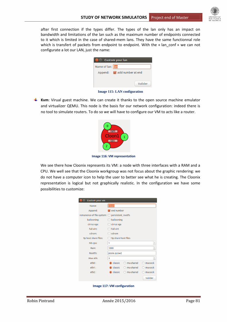
STUDY OF NETWORK SIMULATORS Project end of Master
Robin Pintrand Année 2015/2016 Page 81
after first connection if the types differ. The types of the lan only has an impact on bandwidth and limitations of the lan such as the maximum number of endpoints connected to it which is limited in the case of shared-mem lans. They have the same functionnal role which is transfert of packets from endpoint to endpoint. With the « lan_conf » we can not configurate a lot our LAN, just the name:
Image 115: LAN configuration
Kvm: Virual guest machine. We can create it thanks to the open source machine emulator
and virtualizer QEMU. This node is the basis for our network configuration: indeed there is
no tool to simulate routers. To do so we will have to configure our VM to acts like a router.
Image 116: VM representation
We see there how Cloonix represents its VM: a node with three interfaces with a RAM and a
CPU. We well see that the Cloonix workgroup was not focus about the graphic rendering: we
do not have a computer icon to help the user to better see what he is creating. The Cloonix
representation is logical but not graphically realistic. In the configuration we have some
possibilities to customize:
Image 117: VM configuration

STUDY OF NETWORK SIMULATORS Project end of Master
Robin Pintrand Année 2015/2016 Page 82
Here the most important is the line « Rootfs »: we chose here the quemu VM image to simulate.
Indeed, when we install Cloonix we have to download at least one of the guests proposed by Cloonix
on its website. Careful here, we can not download all the images we want: for example the Cisco
images we used with GNS3 are not supported. We really have to use the images provided on the
website. For exemple here we use and image called « jessie.qcow2 ». But we are going to see that it
is possible to modify the configuration of this VM to create another image: that is how we are going
to create router from the basic proposed VM.
About the others customizations we notice that we can have more than 3 interfaces if needed (15
maximum). The « ballooning » option is also interesting to use less RAM on our host computer.
Notice that when we create a VM model we have to chose a generic name: for example if we want to
create 3 PCs, we write just « PC » in the configuration name case. After, Cloonix will add a number at
the end for every VM created with that configuration type. On each VM, we can access to its consol
terminal by double-clicking on it.
Tap: A link to a tap interface of the host. It is a way to connect Cloonix to a physical interface.
The tap is defined by a name and its interface type :
Image 118 : Tap configuration
Sncf: A sniffer that collects the packets between two interfaces and store them in a file. The
snf can save a limited number of packets in a pcap file. The default file is
« tmp/cloonix_snf0.pcap ». To use it, we just call wireshark with this file as parameter.
The Sniffer is defined as same as the Tap:
Image 119 : Sniffer configuration
C2C (Cloonix to Cloonix): This tool simulates wires between vm guests of different servers.
Indeed, as I said before we can use different Cloonix servers: nemo or mito for example. So
we can open a GUI for each servers and connecte the different topology using the C2C tool.
But it does not add functionnality.
That is all we can create and simulate with Cloonix: there is no switchs, hubs to simulate or others
types of devices. We create the links between nodes by clicking on a LAN and a VM interface and
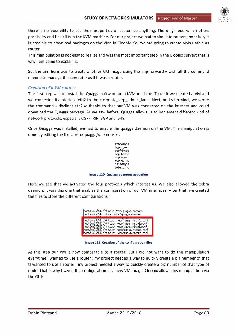
STUDY OF NETWORK SIMULATORS Project end of Master
Robin Pintrand Année 2015/2016 Page 83
there is no possibility to see their properties or customize anything. The only node which offers
possibility and flexibility is the KVM machine. For our project we had to simulate routers, hopefully it
is possible to download packages on the VMs in Cloonix. So, we are going to create VMs usable as
router.
This manipulation is not easy to realize and was the most important step in the Cloonix survey: that is
why I am going to explain it.
So, the aim here was to create another VM image using the « ip forward » with all the command
needed to manage the computer as if it was a router.
Creation of a VM router:
The first step was to install the Quagga software on a KVM machine. To do it we created a VM and
we connected its interface eth2 to the « cloonix_slirp_admin_lan ». Next, on its terminal, we wrote
the command « dhclient eth2 »: thanks to that our VM was connected on the internet and could
download the Quagga package. As we saw before, Quagga allows us to implement different kind of
network protocols, especially OSPF, RIP, BGP and IS-IS.
Once Quagga was installed, we had to enable the quagga daemon on the VM. The manipulation is
done by editing the file « /etc/quagga/daemons » :
Image 120: Quagga daemons activation
Here we see that we activated the four protocols which interest us. We also allowed the zebra
daemon: it was this one that enables the configuration of our VM interfaces. After that, we created
the files to store the different configurations:
Image 121: Creation of the configuration files
At this step our VM is now comparable to a router. But I did not want to do this manipulation
everytime I wanted to use a router : my project needed a way to quickly create a big number of that
tI wanted to use a router : my project needed a way to quickly create a big number of that type of
node. That is why I saved this configuration as a new VM image. Cloonix allows this manipulation via
the GUI:

STUDY OF NETWORK SIMULATORS Project end of Master
Robin Pintrand Année 2015/2016 Page 84
Image 122: Creation of a new VM filesystem
We see on this image that we had now a second type of VM named « jessie-router.qcow2 » which
was stored in the Cloonix tree files. After this manipulation I could creat and implement networks
with the two following node types:
The PC nodes using the « jessie.qcow2 » filesystem.
The Router nodes using the « jessie-router.qcow2 » filesystem we created and saved.
Finally the last visible section on the image 101 allows us to simply save a network topology in a file,
or delete it definetly. The motion « Previous warning » prints the potential issues during the nodes
creation. « Hidden/Visible » simply let the choice to the user about the print of the LAN
« cloonix_slirp_admin_lan »: if we do not want to connect our VM to the internet this LAN is not
needed. And to finish, the option « Motion » is here to start or stop the automatic nodes placement.
By default, its value is « go » so we can create nodes and Cloonix automatically place them.
So we see there how to use Cloonix: this software is based only on its kvm machine. Hopefully, the
possibility to connect them to the internet allows us to modify them to use them as routers. Without
that this simulator will not have been usable for our project.
But we already can say that the Cloonix GUI is realy poor. First, the handling is quite difficult because
of the paucity of information on the Cloonix website. After, exept the VM configuration, there is
really few possibilities to configurate our network: nothing for the links, no switchs, no servers… Even
for the grafical rendering we have nothing to customize our network: write the network addresses,
some figures, etc. Cloonix is only oriented on their KVM machine.
Features and characteristics
This part will be mainly centered about the functionnalities offered by the KVM router. What is
possible to do with this only one configurationable node?
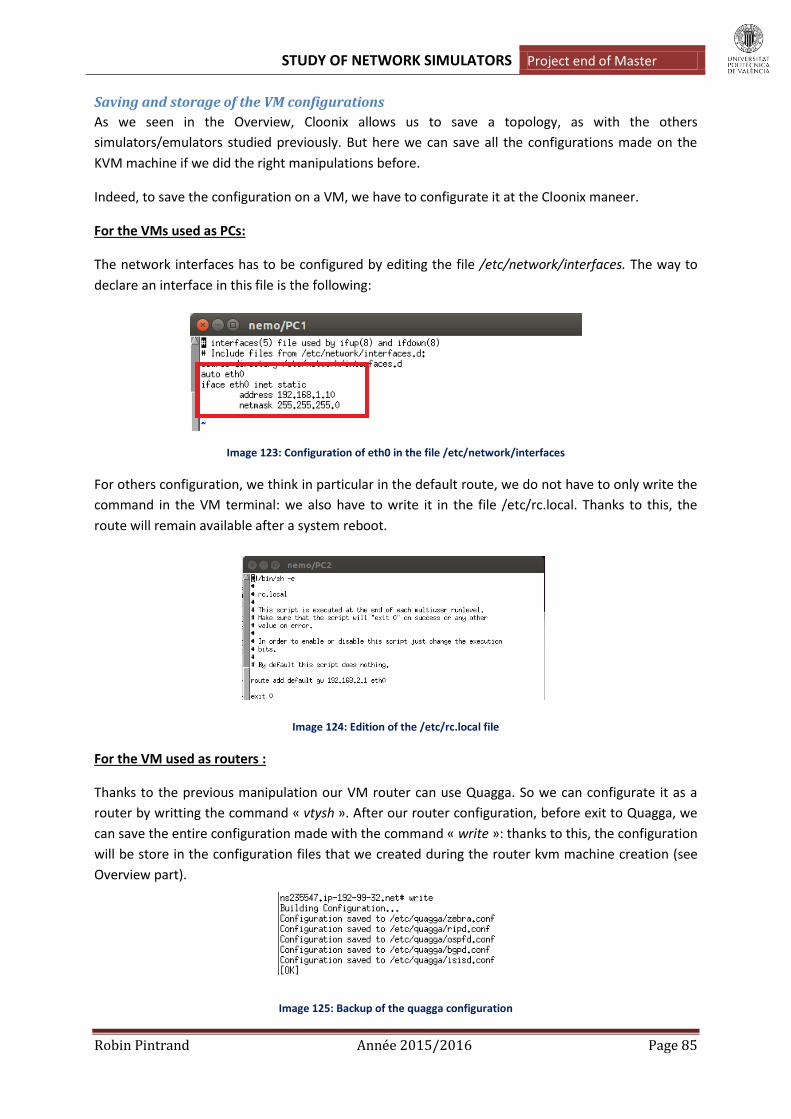
STUDY OF NETWORK SIMULATORS Project end of Master
Robin Pintrand Année 2015/2016 Page 85
Saving and storage of the VM configurations
As we seen in the Overview, Cloonix allows us to save a topology, as with the others
simulators/emulators studied previously. But here we can save all the configurations made on the
KVM machine if we did the right manipulations before.
Indeed, to save the configuration on a VM, we have to configurate it at the Cloonix maneer.
For the VMs used as PCs:
The network interfaces has to be configured by editing the file /etc/network/interfaces. The way to
declare an interface in this file is the following:
Image 123: Configuration of eth0 in the file /etc/network/interfaces
For others configuration, we think in particular in the default route, we do not have to only write the
command in the VM terminal: we also have to write it in the file /etc/rc.local. Thanks to this, the
route will remain available after a system reboot.
Image 124: Edition of the /etc/rc.local file
For the VM used as routers :
Thanks to the previous manipulation our VM router can use Quagga. So we can configurate it as a
router by writting the command « vtysh ». After our router configuration, before exit to Quagga, we
can save the entire configuration made with the command « write »: thanks to this, the configuration
will be store in the configuration files that we created during the router kvm machine creation (see
Overview part).
Image 125: Backup of the quagga configuration

STUDY OF NETWORK SIMULATORS Project end of Master
Robin Pintrand Année 2015/2016 Page 86
If we configurate our PCs in this way, the « Save Topo » option will store the entire configuration. So
it will possible to reuse a network topology saved without any new manipulations.
Routing protocols
Thanks to the Quagga support, we can say that Cloonix is able to implement and simulate the action
of our four routing protocols: RIP, OSPF, IS-IS and BGP. By default no, but we have previously seen
the manipulation to make it possible. Of course, the entire configuration has to be done in the VM
router terminal: there is no services who facilitate the router configuration as with Core or Immunes.
In terms of commands, nothing new, it is the Quagga syntax as it was the case withe Immunes, Core
or again Marionnet. The way to configurate our networks is exactly the same so. Only one important
difference: we shall not forget that we are using PCs transform to routers, so this is an absolutly
necessary command to write in the Quagga vtysh: « ip forwarding ». This command activate the
routing functionnality on a computer, so we have to write it on every PC used as router if we want
that routes will be sent.
But the biggest problem with Cloonix is the memory size needed to create a network: to create and
simulate node we have to emulate a PC image with Qemu. This action cost a lot of memory space, so
much so it is impossible to create really big network if we have installed Cloonix on Vmware Virtual
Machine. For example the image « jessie-router.qcow » take 1.7 Go for itself. I made a basical
network to test Cloonix at the start: it was only composed by 3 VM routers and 2 VM PCs but it size
was already 1Go! So we well see that if we create big topology, with several VMs using different
images, we have to allowate a lot of space to our VMware machine. I built my VM with 14 Go of
memory and it was not enough to save different examples. Another thing is the RAM allocated at
each VM: by default we saw in the Overview than the value is 1000 Mo. This value is way too much if
we want to create big network. If each KVM machine uses 1000 Mo for the RAM we can not create
more than 5 machines. So we have to reduce this allocation but not to much or the running
application will be extremly slow and unsuable.
Now, about the interconnection of networks using different kind of routing protocol: we have the
same problem that occured with Marionnet. Indeed, Quagga does not allow to redistribute BGP (or
another protocol) routes in an IS-IS network. IS-IS is available, but have to create a topology only
using this protocol. However, it is possible to redistribute BGP in OSPF or RIP.
However, to validate the fact that Cloonix is a simulator which answers to our requirements in terms
of routingprotocol, we are going to show one global example but not as big as we would have
wanted :
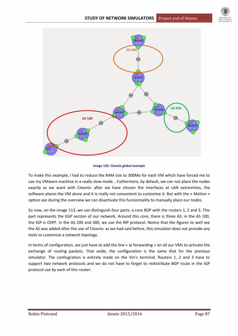
STUDY OF NETWORK SIMULATORS Project end of Master
Robin Pintrand Année 2015/2016 Page 87
Image 126: Cloonix global example
To make this example, I had to reduce the RAM size to 300Mo for each VM which have forced me to
use my VMware machine in a really slow mode… Futhermore, by default, we can not place the nodes
exactly as we want with Cloonix: after we have chosen the interfaces at LAN extremities, the
software places the VM alone and it is really not convenient to customize it. But with the « Motion »
option see during the overview we can disactivate this funcionnality to manually place our nodes.
So now, on the image 113, we can distinguish four parts: a core BGP with the routers 1, 2 and 3. This
part represents the EGP section of our network. Around this core, there is three AS: in the AS 100,
the IGP is OSPF. In the AS 200 and 300, we use the RIP protocol. Notice that the figures to well see
the AS was added after the use of Cloonix: as we had said before, this simulator does not provide any
tools to customize a network topology.
In terms of configuration, we just have to add the line « ip forwarding » on all our VMs to activate the
exchange of routing packets. That aside, the configuration is the same that for the previous
simulator. The confiugration is entirely made on the Vm’s terminal. Routers 1, 2 and 3 have to
support two network protocols and we do not have to forget to redistribute BGP route in the IGP
protocol use by each of this router:

STUDY OF NETWORK SIMULATORS Project end of Master
Robin Pintrand Année 2015/2016 Page 88
Image 127: R3 and R2 configuration
After the configuration done on all the routers, we can see all the networks are well learnt by each
router. The routes are well redistributed to, so the end route router also knows all the topology:
Image 128: Routes learnt on a BPG and OSPF router
As shown by the images, the routes are well redistributed and communicated following the protocol used by the router. Finally we try a ping between PC4 and H1 to validate our example:
Image 129: ping from PC1 to Router 2 and Router 6

STUDY OF NETWORK SIMULATORS Project end of Master
Robin Pintrand Année 2015/2016 Page 89
Security
Quagga is usefull to simulate and implement routing protocol, but it does not provide any tools to
use security commands on a router, just as Cloonix. So we have nothing to secure our networks
because it is impossible to use NAT commands, ipsec, iptables, etc.
Hosts
Cloonix does not provide VM pre-configured which simulate the action of a server. But as we can
connect our VM to the internet it is possible to install a DHCP server on it for example. We just have
to install the package « dhcp3-server » and proceed to the installation following tutorial on a website.
But there is no point because we do not use the Cloonix functionnalities: the manipulation would be
exactly the same on your physical computer.
Switch
As we notice before, Cloonix does not provide any tools to simulate a switch. So we have to connect
directly PCs and routers, what is far from the reality. Moreover, we can not simulate level 2 network
issues as Spanning Tree or create VLAN.
Deepening and Notice
Wireshark
This tool is not incorporated in Cloonix. The sniffer provide by Cloonix have to be placed between
two interfaces and saved the packets in a file store in « /tmp ». The Cloonix documentation just
recommands to install Wireshark to open this file to well see the information store. Fore example we
see on the image 117 the informations saved in the file « cloonix_snf1.pcap » :
Image 130: File cloonix_snf1.pcap opened in Wireshark
IPV6
The VM used by Cloonix support IPv6 addresses. We just have to modificate the file
/etc/networks/interfaces as following:
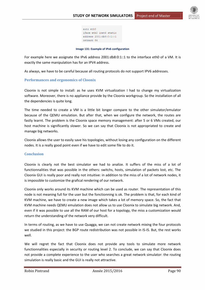
STUDY OF NETWORK SIMULATORS Project end of Master
Robin Pintrand Année 2015/2016 Page 90
Image 131: Example of IPv6 configuration
For example here we assignate the IPv6 address 2001:db8:0:1::1 to the interface eth0 of a VM. It is
exactly the same manipulation has for an IPV4 address.
As always, we have to be careful because all routing protocols do not support IPV6 addresses.
Performances and ergonomics of Cloonix
Cloonix is not simple to install: as he uses KVM virtualization I had to change my virtualization
software. Moreover, there is no appliance provide by the Cloonix workgroup. So the installation of all
the dependencies is quite long.
The time needed to create a VM is a little bit longer compare to the other simulator/emulator
because of the QEMU emulation. But after that, when we configure the network, the routes are
fastly learnt. The problem is the Cloonix space memory management: after 5 or 6 VMs created, our
host machine is significantly slower. So we can say that Cloonix is not appropriated to create and
manage big networks.
Cloonix allows the user to easily save his topologies, without losing any configuration on the different
nodes. It is a really good point even if we have to edit some file to do it.
Conclusion
Cloonix is clearly not the best simulator we had to analize. It suffers of the miss of a lot of
functionnalities that was possible in the others: switchs, hosts, simulation of packets lost, etc. The
Cloonix GUI is really poor and really not intuitive: in addition to the miss of a lot of network nodes, it
is impossible to customize the grafical rendering of our network.
Cloonix only works around its KVM machine which can be used as router. The representation of this
node is not meaning full for the user but the fonctionning is ok. The problem is that, for each kind of
KVM machine, we have to create a new image which takes a lot of memory space. So, the fact that
KVM machine needs QEMU emulation does not allow us to use Cloonix to simulate big network. And,
even if it was possible to use all the RAM of our host for a topology, the miss a customization would
return the understanding of the network very difficult.
In terms of routing, as we have to use Quagga, we can not create network mixing the four protocols
we studied in this project: the BGP route redistribution was not possible in IS-IS. But, the rest works
well.
We will regret the fact that Cloonix does not provide any tools to simulate more network
functionnalities especially in security or routing level 2. To conclude, we can say that Cloonix does
not provide a complete experience to the user who searches a great network simulator: the routing
simulation is really basic and the GUI is really not attractive.

STUDY OF NETWORK SIMULATORS Project end of Master
Robin Pintrand Année 2015/2016 Page 91
III/. Comparatives tables
To finish our report, we are now presenting some comparative tables. These tables will allows us to
summarize all the features studied during this project for each simulator. Furthermore, thanks to
them, it will be easier to compare the simulators and well see which are the most adapted for an
educational purpose.
Software type and installation
Core Immunes Marionnet GNS3 Cloonix
Software type
Simulator Simulator Simulator Emulator/Simulator Emulator/Simulator
Installation Appliance download
Appliance download
Download the script + configuration files
Download the software on the website + Download routers images
Download the scripts + configuration file + download PCs images
Ease of installation
Easy Easy Medium Easy Difficult
Size after installation
About 6 Go About 6 Go About 5 Go Depends of the images number downloaded
Depends of the images number downloaded
Table 2: Software type and installation
GNS3 and Cloonix are the only ones to use real images to works: GNS3 use Cisco images to emulate
its routers and we have seen all the benefits it brings. Cloonix also use images, but only PCs images
so the benefit is less interesting for us. The drawback with this emulator is the images memory size:
they take, in general, 1 Go on our VM. So, the management of the hard disk is more difficult than
with simulators. However, GNS3 ans Cloonix are also simulator because they do not use images for
the other nodes: switchs, sniffers, hubs…
In terms of installation, we can say that Core and Immunes are the simplest to install: thanks to their
workgroup, we just have to download the appliance and open it with virtualization software as
VirtualBox. GNS3 is also really simple to install but we have to find Cisco images on the internet to
really use it correctly.

STUDY OF NETWORK SIMULATORS Project end of Master
Robin Pintrand Année 2015/2016 Page 92
Simulators GUI
Core Immunes Marionnet GNS3 Cloonix
Handling Easy Easy Medium Easy Difficult
Tools : Router yes yes yes yes no Switch yes yes yes yes no Hub yes yes yes yes no Server yes yes No no no LAN cloud no no no yes no Virtual external socket
yes yes yes no yes
Tunnels yes no no no yes Wireless tools yes no no no no
GUI size Adequate Adequate Insufficient Adequate Insufficient
Tools for customization
yes yes no yes no
Graphical configuration
yes yes no no no
Table 3: Simulators GUI
We decide to class the Marionnet handling in « Medium » because of its cumbersome: the fact that
the links can not be created easly more the experience more laborious. But we admit that for an
educationnal purpose, have to creat manually all the links can be interesting.
When we speak about the « GUI size », we want to illustrate if the size is enough to simulate big
topology, composed by at least 10 routers. And clearly, Marionnet and Cloonix are not built to
support that kind of simulation.
About the « Grafical configuration », we speak here about the router configuration: is it possible to
configure the routers otherwise than via a terminal? Core and Immunes are the only ones to propose
this alternative by directly editing the routers configuration files.
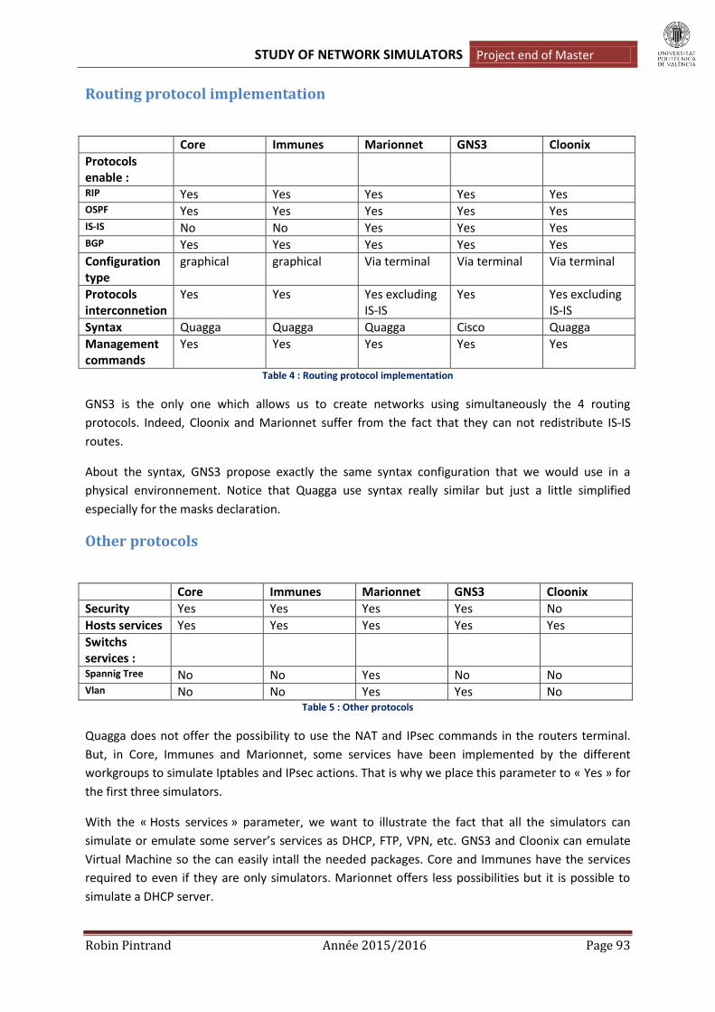
STUDY OF NETWORK SIMULATORS Project end of Master
Robin Pintrand Année 2015/2016 Page 93
Routing protocol implementation
Core Immunes Marionnet GNS3 Cloonix
Protocols enable :
RIP Yes Yes Yes Yes Yes OSPF Yes Yes Yes Yes Yes IS-IS No No Yes Yes Yes BGP Yes Yes Yes Yes Yes
Configuration type
graphical graphical Via terminal Via terminal Via terminal
Protocols interconnetion
Yes Yes Yes excluding IS-IS
Yes Yes excluding IS-IS
Syntax Quagga Quagga Quagga Cisco Quagga
Management commands
Yes Yes Yes Yes Yes
Table 4 : Routing protocol implementation
GNS3 is the only one which allows us to create networks using simultaneously the 4 routing
protocols. Indeed, Cloonix and Marionnet suffer from the fact that they can not redistribute IS-IS
routes.
About the syntax, GNS3 propose exactly the same syntax configuration that we would use in a
physical environnement. Notice that Quagga use syntax really similar but just a little simplified
especially for the masks declaration.
Other protocols
Core Immunes Marionnet GNS3 Cloonix
Security Yes Yes Yes Yes No
Hosts services Yes Yes Yes Yes Yes
Switchs services :
Spannig Tree No No Yes No No Vlan No No Yes Yes No
Table 5 : Other protocols
Quagga does not offer the possibility to use the NAT and IPsec commands in the routers terminal.
But, in Core, Immunes and Marionnet, some services have been implemented by the different
workgroups to simulate Iptables and IPsec actions. That is why we place this parameter to « Yes » for
the first three simulators.
With the « Hosts services » parameter, we want to illustrate the fact that all the simulators can
simulate or emulate some server’s services as DHCP, FTP, VPN, etc. GNS3 and Cloonix can emulate
Virtual Machine so the can easily intall the needed packages. Core and Immunes have the services
required to even if they are only simulators. Marionnet offers less possibilities but it is possible to
simulate a DHCP server.

STUDY OF NETWORK SIMULATORS Project end of Master
Robin Pintrand Année 2015/2016 Page 94
About the switch services, Marionnet is the only one to propose a VDE switch terminal. Thanks to
that it is possible to implement the Spanning Tree protocol and creat VLANs. GNS3 also offer the
possibility to create VLAN thanks to the switch configuration window but it is impossible to active the
Spanning Tree.
Other Tools
Core Immunes Marionnet GNS3 Cloonix
Errors simulation
Yes Yes Yes No No
Wireshark No Yes Yes Yes No
IPv6 Yes Yes Yes Yes Yes
Save of the routers configuration
Yes Yes No No Yes
Table 6 : Other tools
We remark that GNS3, which was to there the most powerful software, does not provide a system to
simulate the lost of some packets, delay, gigue… It is due to the fact that in GNS3 we can not
customize the links. That is the main drawback for this simulator/emulator, especially if we want to
test the robustness of an infrastructure.
Notice that Cloonix is the only software using a configuration via terminal which allows saving the
routers configuration easily. That is a really interesting benefit but Cloonix have also too many
drawbacks to be used in an educational purpose.

STUDY OF NETWORK SIMULATORS Project end of Master
Robin Pintrand Année 2015/2016 Page 95
Conclusion and future works
This project was the opportunity to discover various network simulators and to learn more about the
interconnection of routing protocols. The study allowed us to discover the benefits and the
drawbacks of every softwares. It seems obvious that all were created in different purposes: some of
them in educational purposes centered on the configuration of the feigned routers. And others more
directed on the emulation of images routers or PCs.
Our first purpose was to find simulators offering an experience close to the reality while taking into
account 4 protocols RIP, OSPF, ISIS and BGP. If every studied simulator answers certain expectations,
none seems perfect. However, the simulator / emulator GNS3 distances itself from part its very
complete aspect: Thanks to its capacity to emulate images of CISCO routers, it allows exactly the
same syntax for the routers configuration that during practical class on physical machines.
Furthermore, it offers a complete pallet allowing simulating the other components of a network
(switch, Hub, PC) thanks to an attractive GUI, adapted to the big sizes topology. Its only weakness in
the face of its competitors is the fact of not being able to manage links and thus to simulate packets
losses.
In a more general way, the in-depth study of every simulator now allows us to associate each of them
with a precise use: simulations of errors, protection, graphic configuration, speed …
During this project, we have focused on capacities proposed by simulators from the installation. But
we saw that some of them could be improved by the user thanks to the creation of new services (in
particular Core). A future interesting work would thus be to try to complete one of these simulators
to make it closer to the reality. This work should be made in agreement with the workgroup
managing the simulator chooses so that the fruit of our work can be integrated joined in the future
update.

STUDY OF NETWORK SIMULATORS Project end of Master
Robin Pintrand Année 2015/2016 Page 96
Bibliography
[1] « Open-Source Routing and Network Simulation », http://www.brianlinkletter.com/open-source-
network-simulators. [Online]
[2] « GNS3 The software that empowers networks professionals », https://www.gns3.com. [Online]
[3] « Cloonix Simulator », http://www.cloonix.net. [Online]
[4] « Marionnet, a vitual network laboratory », http://www.marionnet.org. [Online]
[5] « Integrated Multiprotocol Network Emulator/Simulator », http://imunes.net. [Online]
[6] Networks an Communication System Branch « Common Open Research Emulator »,
http://www.nrl.navy.mil/itd/ncs/products/core. [Online]
[7] « Cisco presentation guide », https://www.nanog.org. [Online]
[8] Laurent TOUTAIN, « Réseau Internet : Protocoles, Multicast, Routage, MPLS et Mobilité ».
http://www.techniques-ingenieur.fr [Online]
[9] « Wikipedia, The Free Encyclopedia », https://en.wikipedia.org. [Online]
[10] « Documentation Ubuntu Francophone », https://doc.ubuntu-fr.org. [Online]