surface engineering - الجامعة...
TRANSCRIPT

1
Surface Engineering
(Surface and Coating technologies)
By
Ahmed Al-Ghaban, PhD
Undergraduate studies
Fourth grade year

2
First lecture
• General introduction (preface)
• Why are we interested in surface technology?!
• What are we going to study?!
• What is our final goal?!
• What are we responsible for as material engineer candidates?
• What are the rules to be succeeded?
• Are we going to fulfill our motivation?!

3
Second lecture
• Coatings in general.
• Let us go step by step!
• What do you know about coatings?
• Did you go further?
• Let us state the arts.
• What is must to be known?
• Here we are!!!

4
Second lecture
• SURFACE PREPARATION
The quality of surface preparation, and surface repair on new, or repaint surfaces,
significantly affects the amount of preparatory work that will be required for all
subsequent repaints. Surface preparation and surface repair are the most
important requirements for maximum durability from any paint system. Because
the results of surface preparation and repair are quickly concealed by the first
coat of paint, the effects are not usually evident until premature paint failure
occurs.
The first step should always be a thorough examination of the surface to be
painted, checking for peeling and faded paint, dirt, chalking, grease, cracking,
knots, bare areas, mildew, rust, nail stains and structural problems. All surfaces,
whether painted or unpainted, must be clean, free from shine, sound and dry
prior to finishing.

5
Second lecture
• General surface preparation
LOOSE AND PEELING PAINT
Remove as much loose and peeling paint by scraping, wirebrush or power-
washing the surface.
Feather-sand rough edges smooth until they blend with bare surface.
DIRT, GREASE, OIL, AND UNDER-EAVE DEPOSITS
Remove these deposits by washing with a detergent solution (TSP) or
commercial cleaner recommended for cleaning painted surfaces using a sponge
or brush. Protected areas, such as under eaves and overhangs, need special
attention to remove invisible deposits that can promote a premature peeling
problem. After washing, thoroughly rinse with clean water and allow to dry.

6
Second lecture
• General surface preparation
RUST
Remove all rust by sandblasting, wirebrush, steel wool, sandpaper or naval jelly
(rinse thoroughly). See Iron, Steel and Ferrous Metal section for SSPC
preparation methods.
CRACKS, SPLITS AND OPEN JOINTS
Cracks, or open joints, where water may enter should be caulked with a high-
quality, pintable acrylic caulk. Apply primer over caulked area.
GLOSSY SURFACES
Always dull surfaces with sandpaper or liquid de-glosser. CAUTION - liquid de-
glossers are generally not recommended on surfaces to be painted with water-
based paints.

7
Second lecture
• General surface preparation
PREVIOUSLY COATED SURFACES
Maintenance painting will frequently not permit complete removal of all old
coatings prior to repainting a particular surface. Recognize that any surface
preparation, short of removal of all old coatings, may compromise the service
life of the new coating system. Check compatibility of previously painted
surfaces using a test patch with the coating if there is any doubt on recoatability.

8
Second lecture
• Electroplating
What is Electroplating?
Also knows as electrodeposition, electroplating is using a small sheet of metal in an
electrocytic cell to coat another object. It is used to protect objects from damage against
rusting and corrosion of metals.
The Chemistry behind electroplating is this: the item to be plated by the metal gets the
negative charge and is put into a salt solution of the metal being used to plate the object.
The metal being used to plate the item has a positive charge and is placed in the same
solution. Therefore, the object to be plated is the cathode, and the metal being used to
plate the item is the anode. Because of this, electroplating is a electrolytic cell since the
electrons are flowing from positive to negative, where the metal to be plated is being
reduced and the metal being used in the process is being oxidized.
With the electrons flowing, it is just the law of attraction. The positive ions from the salt
solution and the metal being used to plate "stick" onto the object being plated since it
has a negative charge. The thickness of the metal plating depends on how long you
leave it in the solution, and the flow of electrons.

9
Second lecture
• The anode and cathode in the electroplating cell are both connected to an external supply of direct current — a battery or, more commonly, a rectifier. The anode is connected to the positive terminal of the supply, and the cathode (article to be plated) is connected to the negative terminal. When the external power supply is switched on, the metal at the anode is oxidized from the zero valence state to form cations with a positive charge. These cations associate with the anions in the solution. The cations are reduced at the cathode to deposit in the metallic, zero valence state. For example, in an acid solution, copper is oxidized at the anode to Cu2+ by losing two electrons. The Cu2+ associates with the anion SO42- in the solution to form copper sulfate. At the cathode, the Cu2+ is reduced to metallic copper by gaining two electrons. The result is the effective transfer of copper from the anode source to a plate covering the cathode.
• The plating is most commonly a single metallic element, not an alloy. However, some alloys can be electrodeposited, notably brass and solder.
• Many plating baths include cyanides of other metals (e.g., potassium cyanide) in addition to cyanides of the metal to be deposited. These free cyanides facilitate anode corrosion, help to maintain a constant metal ion level and contribute to conductivity. Additionally, non-metal chemicals such as carbonates and phosphates may be added to increase conductivity.
• When plating is not desired on certain areas of the substrate, stop-offs are applied to prevent the bath from coming in contact with the substrate. Typical stop-offs include tape, foil, lacquers, and waxes.
• The process:

10
Second lecture
Initially, a special plating deposit called a "strike" or "flash" may be used to form avery thin (typically less than 0.1 micrometer thick) plating with high quality and good adherence to the substrate. This serves as a foundation for subsequent plating processes. A strike uses a high current density and a bath with a low ion concentration. The process is slow, so more efficient plating processes are used once the desired strike thickness is obtained.
The striking method is also used in combination with the plating of different metals. If it is desirable to plate one type of deposit onto a metal to improve corrosion resistance but this metal has inherently poor adhesion to the substrate, a strike can be first deposited that is compatible with both. One example of this situation is the poor adhesion of electrolytic nickel on zinc alloys, in which case a copper strike is used, which has good adherence to both.
• Strike

11
Second lecture
A closely related process is brush electroplating, in which localized areas or entire items are plated using a brush saturated with plating solution. The brush, typically a stainless steel body wrapped with a cloth material that both holds the plating solution and prevents direct contact with the item being plated, is connected to the positive side of a low voltage direct-current power source, and the item to be plated connected to the negative. The operator dips the brush in plating solution then applies it to the item, moving the brush continually to get an even distribution of the plating material. Brush electroplating has several advantages over tank plating, including portability, ability to plate items that for some reason cannot be tank plated (one application was the plating of portions of very large decorative support columns in a building restoration), low or no masking requirements, and comparatively low plating solution volume requirements. Disadvantages compared to tank plating can include greater operator involvement (tank plating can frequently be done with minimal attention), and inability to achieve as great a plate thickness.
• Brush electroplating

12
Second lecture
Usually an electrolytic cell (consisting of two electrodes, electrolyte, and external source of current) is used for electrodeposition. In contrast, an electroless deposition process uses only one electrode and no external source of electric current. However, the solution for the electroless process needs to contain a reducing agent so that the electrode reaction has the form:
In principle any water-based reducer can be used although the redox potential of the reducer half-cell must be high enough to overcome the energy barriers inherent in liquid chemistry. Electroless nickel plating uses hypophosphite as the reducer while plating of other metals like silver, gold and copper typically use low molecular weight aldehydes.
A major benefit of this approach over electroplating is that power sources and plating baths are not needed, reducing the cost of production. The technique can also plate diverse shapes and types of surface. The downside is that the plating process is usually slower and cannot create such thick plates of metal. As a consequence of these characteristics, electroless deposition is quite common in the decorative arts.
• Electroless deposition

13
Second lecture
Electroplating has so many real-world applications that it is invaluable to modern society. Sometimes, it is impractical or impossible to manufacture a product out of a metal with certain properties. With electroplating, however, one is able to coat the surface of an object with a rare or otherwise impractical metal in order to bestow the properties of that metal onto said object. Tin is used to coat cans in order to prevent corrosion, while a chromium coating will increase a metal’s resistance to wear. Similarly, silver and gold are used to coat silverware and jewelry to prevent corrosion and increase value. Another application of electroplating is the thickening of an object.
However, although this process is very useful, it can also be dangerous. In the real world, electroplating is done in a large scale, and so a large amount of waste is produced. The resulting waste is called wastewater in the industry, and must be treated before it is suitable for the sewage system. The wastewater is very corrosive, and contains very toxic heavy metals. Therefore, dispensing it untreated into water sources would harm wildlife and potentially contaminate drinking water. Treating the wastewater, however, must also be done with much care due to its toxicity and corrosiveness. Proper procedure must be followed or else the industrial chemist responsible for this treatment could undergo chemical burns or poisoning.
• Benefits and hazards

14
Second lecture
Electroplating changes the chemical, physical, and mechanical properties of the workpiece. An example
of a chemical change is when nickel plating improves corrosion resistance. An example of a physical
change is a change in the outward appearance. An example of a mechanical change is a change in
tensile strength or surface hardness which is a required attribute in tooling industry.
• Effects
Cleanliness is essential to successful electroplating, since molecular layers of oil can prevent adhesion
of the coating. ASTM B322 is a standard guide for cleaning metals prior to electroplating. Cleaning
processes include solvent cleaning, hot alkaline detergent cleaning, electro-cleaning, and acid treatment
etc. The most common industrial test for cleanliness is the waterbreak test, in which the surface is
thoroughly rinsed and held vertical. Hydrophobic contaminants such as oils cause the water to bead and
break up, allowing the water to drain rapidly. Perfectly clean metal surfaces are hydrophilic and will
retain an unbroken sheet of water that does not bead up or drain off. ASTM F22 describes a version of
this test. This test does not detect hydrophilic contaminants, but the electroplating process can displace
these easily since the solutions are water-based. Surfactants such as soap reduce the sensitivity of the
test and must be thoroughly rinsed off.
• Cleanliness

15
• Anodizing process first used in industry in 1923 to protect Duralumin seaplane
parts from corrosion using chromic acid.
• Aluminum is most widely anodized metal
• Magnesium, Titanium, and Zinc are capable of being anodized but not used to a
wide extent
• Other metals such as tin and copper can be anodized, but rarely practiced
3rd lecture Anodizing Process
Background
Basic Concept •Creates or thickens an oxide layer on surface of metal.
•Allows electrical insulation of the given metal.
•Creates opportunity of various decorative effects: dyeing, brightening, preservation
of surface texture.
•Increases hardness of the metal, improves corrosion and wear resistance.
16
3rd lecture • Anodizing
• Is an electrolytic passivation process used to increase the thickness of the natural
oxide layer on the surface of metal parts.
• The process is called "anodizing" because the part to be treated forms the anode
electrode of an electrical circuit.
• Anodizing increases corrosion resistance and wear resistance, and provides better
adhesion for paint primers and glues than bare metal.
• Anodic films can also be used for a number of cosmetic effects, either with thick
porous coatings that can absorb dyes or with thin transparent coatings that add
interference effects to reflected light.
• Anodic films are most commonly applied to protect aluminium alloys, although
processes also exist for titanium, zinc, magnesium, niobium, and tantalum.
• This process is not a useful treatment for iron or carbon steel because these metals
exfoliate when oxidized; i.e. the iron oxide (also known as rust) flakes off, constantly
exposing the underlying metal to corrosion.
17
3rd lecture
• Anodizg changes the microscopic of the surface and changes the crystal structure of the
metal near the surface.
• Anodized aluminum surfaces are harder than aluminum but have low to moderate wear
resistance that can be improved with increasing thickness.
• Anodic films are much stronger and more adherent than most types of paint and metal
plating, but also more brittle.
• This makes them less likely to crack and peel from aging and wear, but more susceptible
to cracking from thermal stress.
In General
The coating thickness and surface characteristics are tightly controlled to meet end
product specifications. Aluminum oxide is an extremely hard material that approaches
the hardness of a diamond. As a result, the aluminum oxide layer provides
excellent wear and corrosion protection
18
3rd lecture
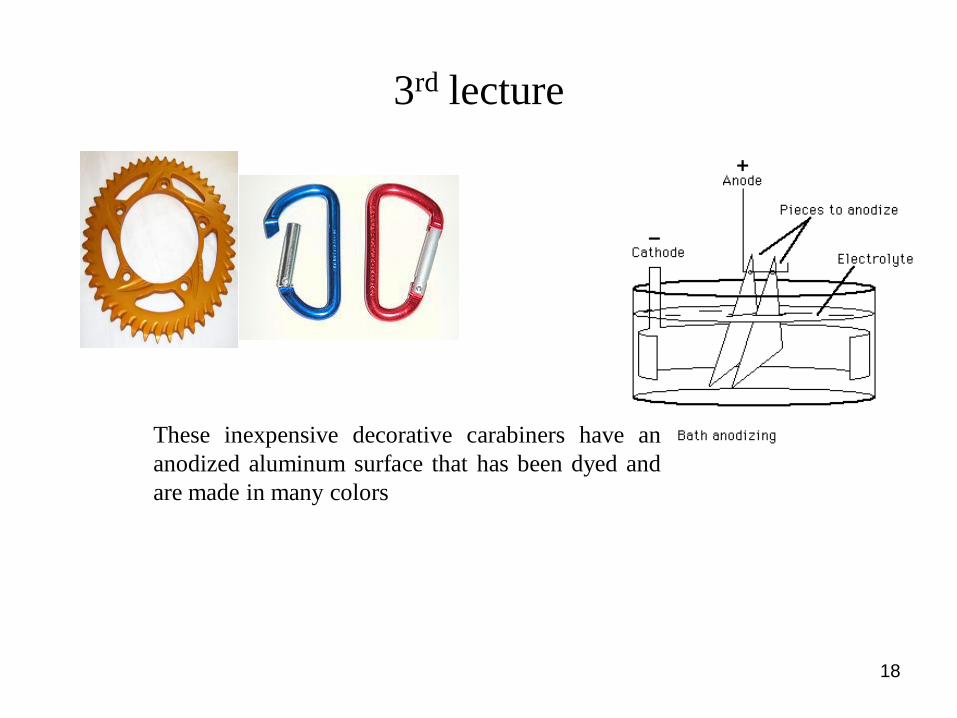
These inexpensive decorative carabiners have an
anodized aluminum surface that has been dyed and
are made in many colors

19
Process
Preceding the anodization process, wrought alloys are cleaned in either a hot soak cleaner or in a solvent bath and
may be etched in sodium hydroxide (normally with added sodium gluconate), ammonium bifluoride or brightened in
a mix of acids. Cast alloys are normally best just cleaned due to the presence of intermetallic substances unless they
are a high purity alloy such as LM0.
The anodized aluminium layer is grown by passing a direct current through an electrolytic solution, with the
aluminium object serving as the anode (the positive electrode). The current releases hydrogen at the cathode (the
negative electrode) and oxygen at the surface of the aluminium anode, creating a build-up of aluminium oxide.
Alternating current and pulsed current is also possible but rarely used. The voltage required by various solutions may
range from 1 to 300 V DC, although most fall in the range of 15 to 21 V. Higher voltages are typically required for
thicker coatings formed in sulfuric and organic acid. The anodizing current varies with the area of aluminium being
anodized, and typically ranges from 30 to 300 amperes/meter² (2.8 to 28 ampere/ft²).
Aluminium anodizing is usually performed in an acid solution which slowly dissolves the aluminium oxide. The acid
action is balanced with the oxidation rate to form a coating with nanopores, 10-150 nm in diameter. These pores are
what allow the electrolyte solution and current to reach the aluminium substrate and continue growing the coating to
greater thickness beyond what is produced by autopassivation. However, these same pores will later permit air or
water to reach the substrate and initiate corrosion if not sealed. They are often filled with colored dyes and/or
corrosion inhibitors before sealing. Because the dye is only superficial, the underlying oxide may continue to provide
corrosion protection even if minor wear and scratches may break through the dyed layer.
Conditions such as electrolyte concentration, acidity, solution temperature, and current must be controlled to allow
the formation of a consistent oxide layer. Harder, thicker films tend to be produced by more dilute solutions at lower
temperatures with higher voltages and currents. The film thickness can range from under 0.5 micrometers for bright
decorative work up to 150 micrometers for architectural applications.
3rd lecture

20
• Process Variables:
– Cycle Time
– Voltage
– Current Density
– Electrolyte Chemistry
– Electrolyte
Concentration
– Electrolyte Temperature
3rd lecture

21
• Entertainment Industry
• Military/Aerospace
• Commercial
Areas of Applications
3rd lecture

22
• DC power source
• Racks or jigs to support work pieces
• Electrolytic solution:
– Sulfuric
– Chromic
– Oxalic
– Phosphoric
• Solution, water, dye, and sealing tanks
Anodizing equipments
3rd lecture

23
3rd lecture
General Questions
Is anodizing environmentally friendly?
Yes, anodize does not entail the use of heavy metals nor does it produce toxic waste.
What substrates or base metals can be anodized?
The three substrates that can be anodized are aluminum, titanium, and magnesium.
Steel or stainless steel cannot be anodized.
What alloys are best for anodizing?
In general, wrought alloy series 1000-7000 provide the best corrosion and aesthetic
properties than cast alloy. Specific alloy choice to match performance needs should be
discussed on a case-by-case basis. For more information on alloy series and their
effects on the anodize process, please visit our Alloy Specs section of the Knowledge
Base.
What is the difference between Type II “conventional anodize” and Type III
“hard anodize”?
Type III or hard anodize offers a more dense aluminum oxide layer. To produce this
requires increased electricity consumption and a super cooled electrolyte bath.
Perhaps the best way to illustrate differences between type II “conventional anodize”
and type III “hard anodize” is in the following chart. Notice the enhanced attributes of
hard anodize versus conventional anodize.

24
3rd lecture

25
Will anodize affect the adhesion of paint or subsequent coatings?
Anodize will promote the adhesion of paint and subsequent coatings.
Will anodizing hide scratches?
Anodizing will provide minimal cover-up for surface scratches because anodize
mimics original substrate finish. To further enhance anodize appearance consider
aggressive etching, hand polishing, or surface blasting.
3rd lecture
26
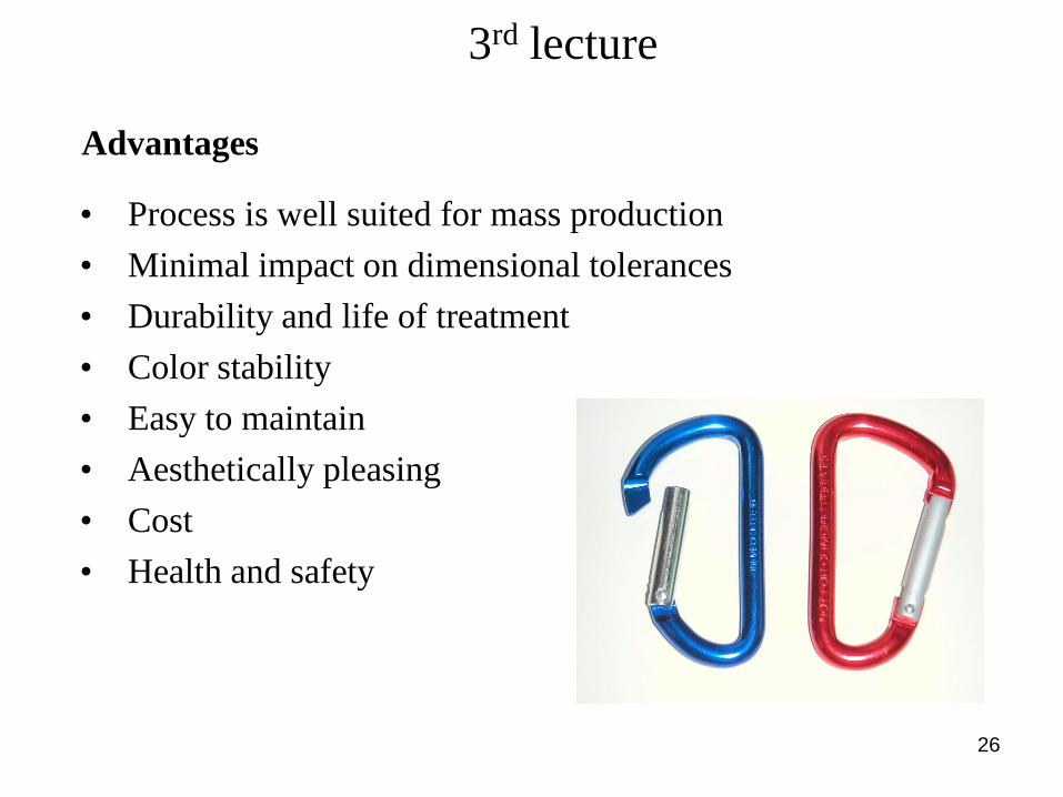
• Process is well suited for mass production
• Minimal impact on dimensional tolerances
• Durability and life of treatment
• Color stability
• Easy to maintain
• Aesthetically pleasing
• Cost
• Health and safety
Advantages
3rd lecture

27
• Limited selection of metals can be anodized
• Bulk anodizing of small items can be difficult or impossible
given certain processes
• Small gaps in coating are produced at points of contact with
jigs or fixtures
• Oxidation layers need to be removed from jigs and fixtures
after every use
Disadvantages
3rd lecture

28
Cladding
4th lecture
Cladding is the bonding together of dissimilar metals. It is
different from fusion welding or gluing as a method to
fasten the metals together. Cladding is often achieved by
extruding two metals through a die as well as pressing or
rolling sheets together under high pressure.

29
4th lecture
• Cladding is the bonding of metals with a thin heated layer of corrosion resistant or
conductive metal, by applying pressure with rolls or other means.
• A typical process is Al-clad in which a corrosion resistant layer of Al-alloy is clad over
Al. Another application is stainless steel clad over steel, reducing the need for using a
full Cr- Ni- alloy base metal.
• Steel wires are clad with Cu using extrusion dies. Here, the surface layer imparts
electrical conductivity, while the core provides strength and rigidity.
• Cladding may be performed on either one or both sides by pressing the sandwich
together under high pressure, and a temperature approximately half of the melting point
of the base metal for a suitable period of time, typically 1 hour.
• This combination of pressure, temperature, and time resulting in a condition at
interface(s) is known as diffusion bonding. When sufficient transfer of atoms at the
interface has occurred - hence the time factor is important - a strong and permanent
bond will have been created. Providing adequate pressure and a sufficiently slow
traverse speed are used, it is possible to diffusion bond clad strip as a continuous
process.
• Surface preparation ensuring thorough cleaning and degreasing is vital for successful
bonding.
Cladding (Hints)

30
4th lecture
Roll welding
In roll welding, two or more layers of different metals are toughly cleaned and
passed through a pair of rollers under sufficient pressure to bond the layers. The
pressure is high enough to deform the metals and reduce the combined thickness
of the clad material. Heat may be applied, but is not necessary if one of the metals
is ductile. Bonding of the sheets can be controlled by painting a pattern on one
sheet; only the bare metal surfaces bond, and the un-bonded portion can be
inflated if the sheet is heated and the coating vaporizes. This is used to make heat
exchangers for refrigeration equipment.

31
4th lecture
Explosive welding
In explosive welding, the pressure to bond the two layers is provided by detonation
of a sheet of chemical explosive. No heat-affected zone is produced in the bond
between metals. The explosion propagates across the sheet, which tends to expel
impurities and oxides from between the sheets. Pieces up to 2 x 6 metres can be
manufactured. The process is useful for cladding metal sheets with a corrosion-
resistant layer.
1 Flyer (cladding). 2 Resolidified zone
(needs to be minimised for welding of
dissimilar materials). 3 Target
(substrate). 4 Explosion. 5 Explosive
powder. 6 Plasma jet

32
4th lecture Laser cladding
Laser cladding is a method of depositing material by which a powdered or wire
feedstock material is melted and consolidated by use of a laser in order to coat part of a
substrate or fabricate a near-net shape part (additive manufacturing technology) .
It is often used to improve mechanical properties or increase corrosion resistance, repair
worn out parts, and fabricate metal matrix composites

33
4th lecture
Process
The powder used in laser cladding is normally of a metallic nature, and is injected
into the system by either coaxial or lateral nozzles. The interaction of the metallic
powder stream and the laser causes melting to occur, and is known as the melt pool.
This is deposited onto a substrate; moving the substrate allows the melt pool to
solidify and thus produces a track of solid metal. This is the most common
technique, however some processes involve moving the laser/nozzle assembly over a
stationary substrate to produce solidified tracks. The motion of the substrate is
guided by a CAD system which interpolates solid objects into a set of tracks, thus
producing the desired part at the end of the trajectory.
The different feeding systems available

34
4th lecture
Process
A great deal of research is now being concentrated on developing automatic laser
cladding machines. Many of the process parameters must be manually set, such as
laser power, laser focal point, substrate velocity, powder injection rate, etc., and thus
require the attention of a specialized technician to ensure proper results. However,
many groups are focusing their attention on developing sensors to measure the
process online. Such sensors monitor the clad's geometry (height and width of
deposited track), metallurgical properties (such as the rate of solidification, and
hence the final microstructure), and temperature information of both the immediate
melt pool and its surrounding areas. With such sensors, control strategies are being
designed such that constant observation from a technician is no longer required to
produce a final product. Further research has been directed to forward processing
where system parameters are developed around specific metallurgical properties for
user defined applications (such as microstructure, internal stresses, delusion zone
gradients, and clad contact angle).
35
4th lecture
Advantages
•Best technique for coating any shape => increase life-time of wearing part by 6-7
years.
•Particular dispositions for repairing parts (ideal if the mould of the part no longer
exist or too long time needed for a new fabrication).
•Most suited technique for graded material application.
•Well adapted for near-net-shape manufacturing.
•Low dilution between track and substrate (unlike other welding processes and
strong metallurgical bond.
•Low deformation of the substrate and small heat affected zone (HAZ).
•High cooling rate => fine microstructure.
•A lot of material flexibility (metal, ceramic, even polymer).
•Built part is free of crack and porosity.
•Compact technology.

36
What is Thermal spraying?
thermal spraying, a group of coating processes in which finely divided metallic or
nonmetallic materials are deposited in a molten or semimolten condition to form a
coating. The coating material may be in the form of powder, ceramic-rod, wire, or
molten materials.
5th lecture
Thermal spraying
37
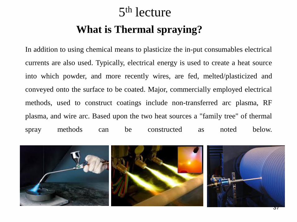
In addition to using chemical means to plasticize the in-put consumables electrical
currents are also used. Typically, electrical energy is used to create a heat source
into which powder, and more recently wires, are fed, melted/plasticized and
conveyed onto the surface to be coated. Major, commercially employed electrical
methods, used to construct coatings include non-transferred arc plasma, RF
plasma, and wire arc. Based upon the two heat sources a "family tree" of thermal
spray methods can be constructed as noted below.
What is Thermal spraying?
5th lecture
38
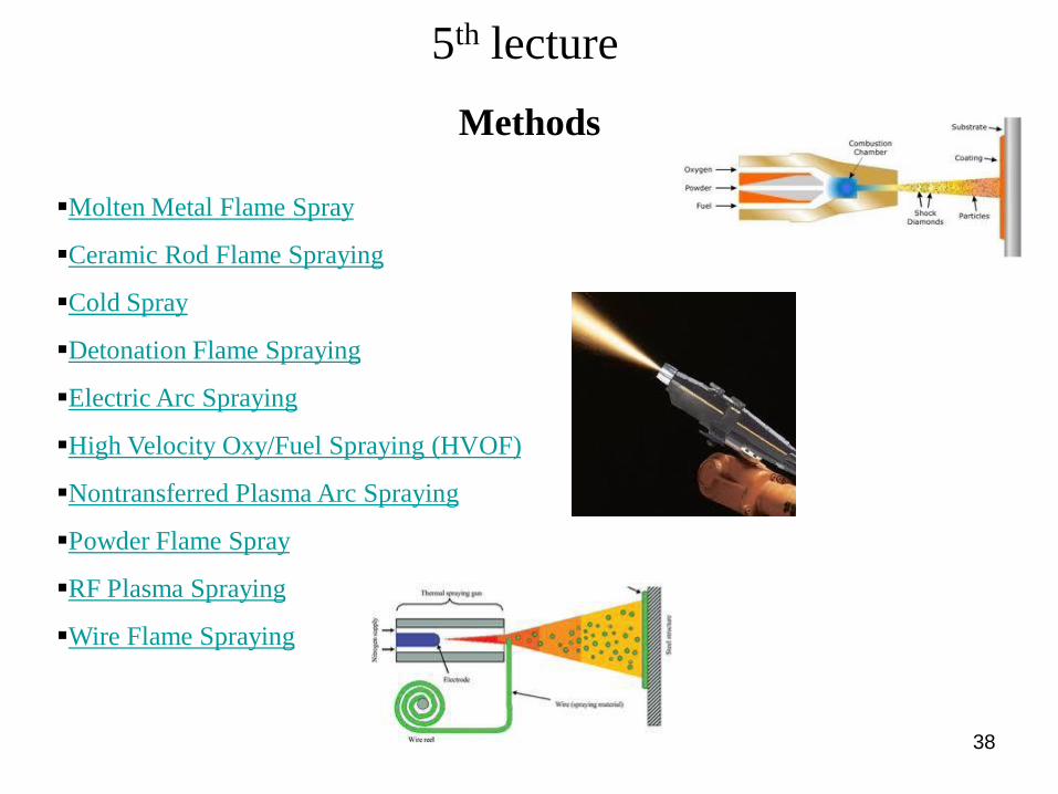
Methods
Molten Metal Flame Spray
Ceramic Rod Flame Spraying
Cold Spray
Detonation Flame Spraying
Electric Arc Spraying
High Velocity Oxy/Fuel Spraying (HVOF)
Nontransferred Plasma Arc Spraying
Powder Flame Spray
RF Plasma Spraying
Wire Flame Spraying
5th lecture

39
Molten Metal Flame Spray
molten metal flame spraying, a thermal spraying process variation in which the metallic
material to be sprayed is in the molten condition.
Methods
5th lecture
40
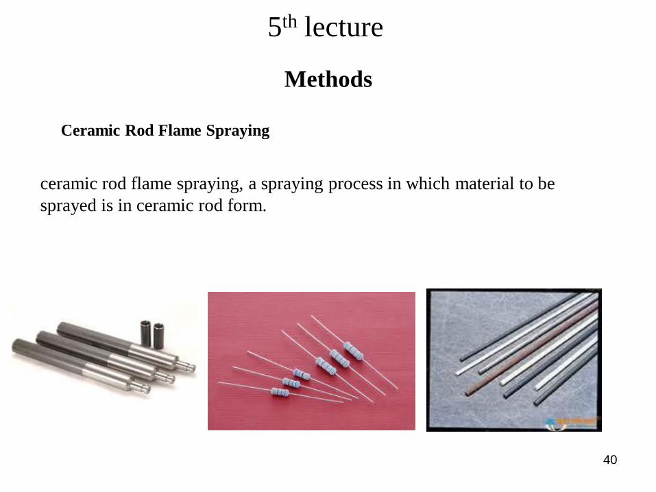
Ceramic Rod Flame Spraying
Methods
ceramic rod flame spraying, a spraying process in which material to be
sprayed is in ceramic rod form.
5th lecture

41
Cold spray
cold spray, a kinetic spray process utilizing supersonic jets of compressed gas
to accelerate near-room temperature powder particles at ultra high velocities.
The unmelted particles, traveling at speeds between 500 to 1,500 m/sec
plastically deform and consolidate on impact with their substrate to create a
coating.
Methods
5th lecture

42
Detonation Thermal Spraying Process
The Detonation gun basically consists of a long water cooled barrel with inlet valves for
gases and powder. Oxygen and fuel (acetylene most common) is fed into the barrel
along with a charge of powder. A spark is used to ignite the gas mixture and the
resulting detonation heats and accelerates the powder to supersonic velocity down the
barrel. A pulse of nitrogen is used to purge the barrel after each detonation. This process
is repeated many times a second. The high kinetic energy of the hot powder particles on
impact with the substrate result in a build up of a very dense and strong coating.
Methods
5th lecture

43
Electric Arc Spraying
electric arc spraying, a thermal spray process in which an arc is struck between two
consumable electrodes of a coating material. Compressed gas is used to atomize and
propel the material to the substrate. (1)
The electric arc spray process utilizes metal in wire form. This process differs from
other thermal spray processes in that there are no external heat sources as in any the
combustion gas/flame spray processes. Heating and melting occur when two electrically
opposed charged wires, comprising the spray material, are fed together in such a manner
that a controlled arc occurs at their intersection. The molten metal is atomized and
propelled onto the prepared workpiece by jets of compressed air or gas.
Methods
5th lecture

44
High Velocity Oxy/Fuel Spraying (HVOF)
The technique was referred to as High Velocity Oxy-Fuel (HVOF). The process utilizes
a combination of oxygen with various fuel gases including hydrogen, propane,
propylene, hydrogen and even kerosene. In the combustion chamber, burning by-
products are expanded and expelled outward through an orifice where at very high
velocities. Often times they produce "shock diamonds" exiting the spray gun as in the
graphic below.
Methods
5th lecture

45
Nontransferred Plasma Arc Spraying
plasma spraying, a thermal spray process in which a nontransterred arc is a source of
heat that ionizes a gas which melts the coating material and propels it to the workpiece.
Plasma is an ionized gaseous cloud composed of free electrons, positive ions, neutral
atoms and molecules. Because of its unique properties some have referred to it as the
"fourth state of matter". Plasma is generated whenever sufficient energy is imparted to a
gas to cause some of it to ionize
Methods
5th lecture

46
Powder Flame Spray
Powder flame spraying, a thermal spray process in which the material to be sprayed is
in powder form.
Powder flame spraying is probably the simplest of all the spray processes to describe -
feed a powder through the center bore of a nozzle where it melts and is carried by the
escaping oxy-fuel gases to the work piece. Unfortunately, this approach yields coatings
high in oxides and with void contents approaching 20 volume percent (v/o).
Methods
5th lecture
47
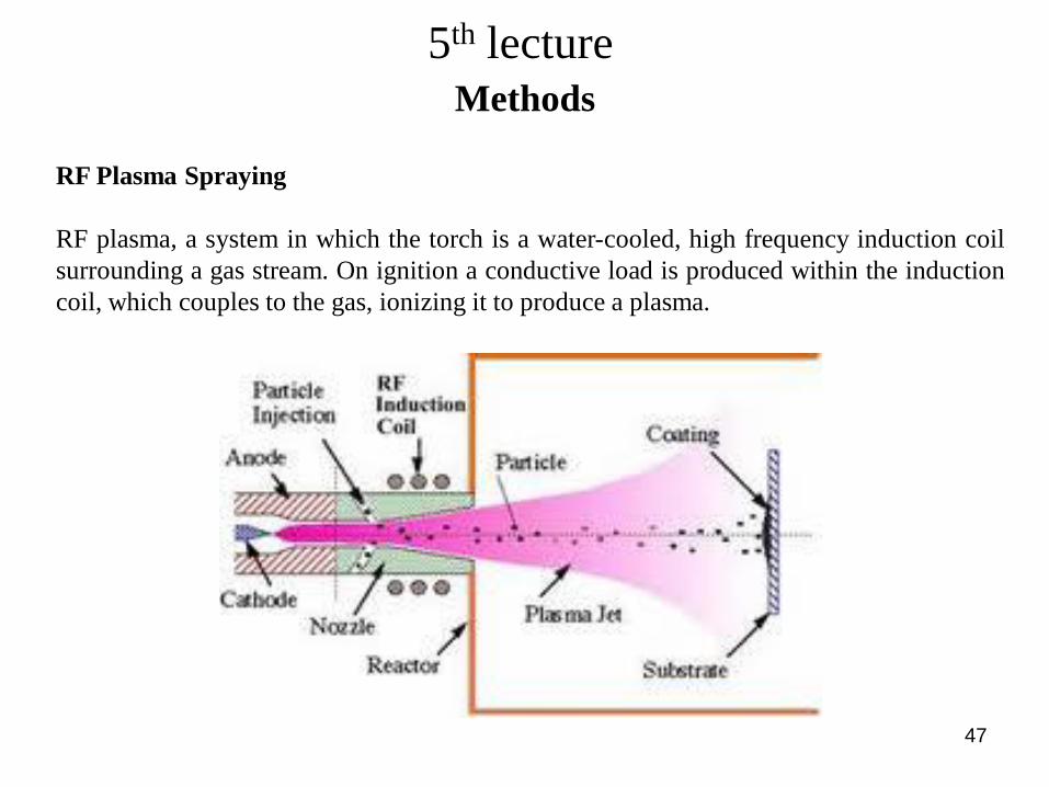
RF Plasma Spraying
RF plasma, a system in which the torch is a water-cooled, high frequency induction coil
surrounding a gas stream. On ignition a conductive load is produced within the induction
coil, which couples to the gas, ionizing it to produce a plasma.
Methods
5th lecture