teller county environmental health
TRANSCRIPT
Teller County Environmental Health
ON-SITE WASTEWATER TREATMENT SYSTEM REGULATION
Adopted 11/23/2015
i
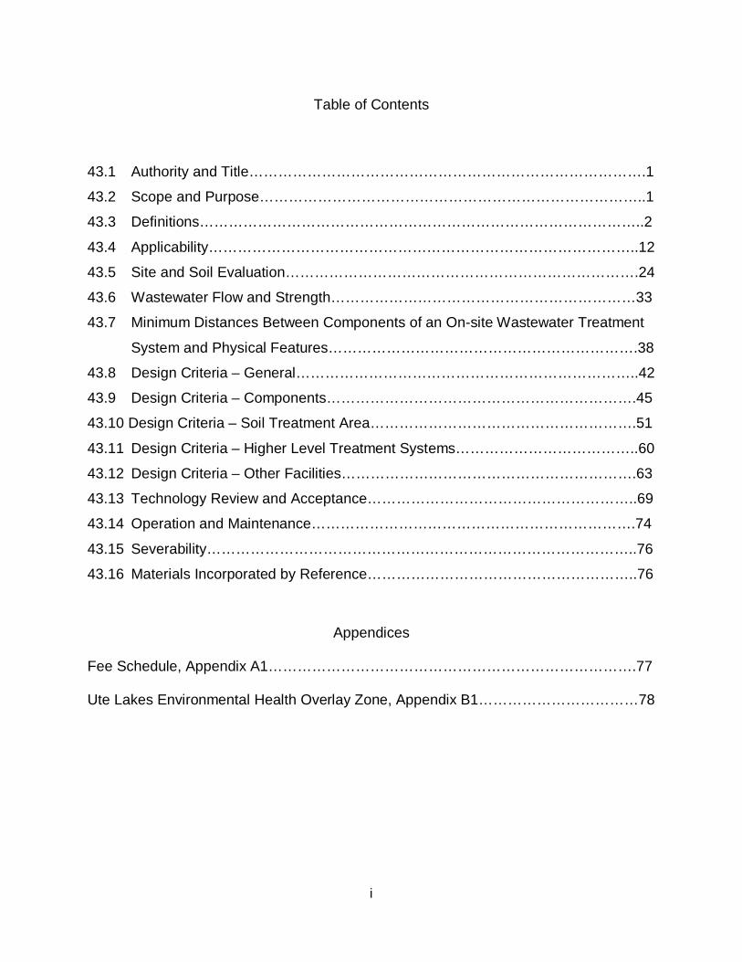
Table of Contents
43.1 Authority and Title……………………………………………………………………….1
43.2 Scope and Purpose……………………………………………………………………..1
43.3 Definitions………………………………………………………………………………..2
43.4 Applicability……………………………………………………………………………..12
43.5 Site and Soil Evaluation……………………………………………………………….24
43.6 Wastewater Flow and Strength………………………………………………………33
43.7 Minimum Distances Between Components of an On-site Wastewater Treatment
System and Physical Features……………………………………………………….38
43.8 Design Criteria – General……………………………………………………………..42
43.9 Design Criteria – Components……………………………………………………….45
43.10 Design Criteria – Soil Treatment Area……………………………………………….51
43.11 Design Criteria – Higher Level Treatment Systems………………………………..60
43.12 Design Criteria – Other Facilities…………………………………………………….63
43.13 Technology Review and Acceptance………………………………………………..69
43.14 Operation and Maintenance………………………………………………………….74
43.15 Severability……………………………………………………………………………..76
43.16 Materials Incorporated by Reference………………………………………………..76
Appendices Fee Schedule, Appendix A1………………………………………………………………….77 Ute Lakes Environmental Health Overlay Zone, Appendix B1……………………………78
1
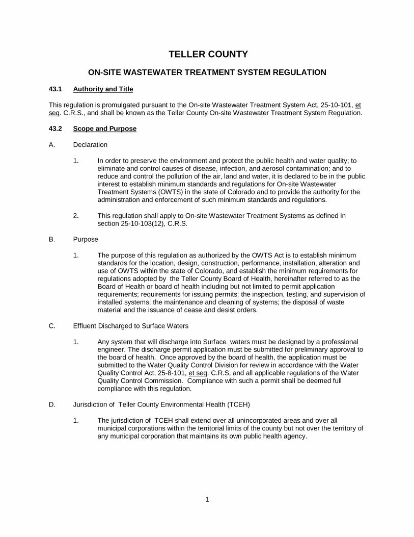
TELLER COUNTY
ON-SITE WASTEWATER TREATMENT SYSTEM REGULATION
43.1 Authority and Title
This regulation is promulgated pursuant to the On-site Wastewater Treatment System Act, 25-10-101, et seq. C.R.S., and shall be known as the Teller County On-site Wastewater Treatment System Regulation.
43.2 Scope and Purpose
A. Declaration
1. In order to preserve the environment and protect the public health and water quality; to eliminate and control causes of disease, infection, and aerosol contamination; and to reduce and control the pollution of the air, land and water, it is declared to be in the public interest to establish minimum standards and regulations for On-site Wastewater Treatment Systems (OWTS) in the state of Colorado and to provide the authority for the administration and enforcement of such minimum standards and regulations.
2. This regulation shall apply to On-site Wastewater Treatment Systems as defined in section 25-10-103(12), C.R.S.
B. Purpose
1. The purpose of this regulation as authorized by the OWTS Act is to establish minimum standards for the location, design, construction, performance, installation, alteration and use of OWTS within the state of Colorado, and establish the minimum requirements for regulations adopted by the Teller County Board of Health, hereinafter referred to as the Board of Health or board of health including but not limited to permit application requirements; requirements for issuing permits; the inspection, testing, and supervision of installed systems; the maintenance and cleaning of systems; the disposal of waste material and the issuance of cease and desist orders.
C. Effluent Discharged to Surface Waters
1. Any system that will discharge into Surface waters must be designed by a professional engineer. The discharge permit application must be submitted for preliminary approval to the board of health. Once approved by the board of health, the application must be submitted to the Water Quality Control Division for review in accordance with the Water Quality Control Act, 25-8-101, et seq. C.R.S, and all applicable regulations of the Water Quality Control Commission. Compliance with such a permit shall be deemed full compliance with this regulation.
D. Jurisdiction of Teller County Environmental Health (TCEH)
1. The jurisdiction of TCEH shall extend over all unincorporated areas and over all municipal corporations within the territorial limits of the county but not over the territory of any municipal corporation that maintains its own public health agency.
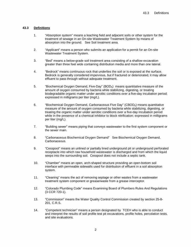
43.3 Definitions
2
43.3 Definitions
1. “Absorption system” means a leaching field and adjacent soils or other system for the treatment of sewage in an On-site Wastewater Treatment System by means of absorption into the ground. See Soil treatment area.
2. “Applicant” means a person who submits an application for a permit for an On-site Wastewater Treatment System.
3. “Bed” means a below-grade soil treatment area consisting of a shallow excavation greater than three feet wide containing distribution media and more than one lateral.
4. “Bedrock” means continuous rock that underlies the soil or is exposed at the surface. Bedrock is generally considered impervious, but if fractured or deteriorated, it may allow effluent to pass through without adequate treatment.
5. “Biochemical Oxygen Demand, Five-Day” (BOD5) means quantitative measure of the amount of oxygen consumed by bacteria while stabilizing, digesting, or treating biodegradable organic matter under aerobic conditions over a five-day incubation period; expressed in milligrams per liter (mg/L).
6. “Biochemical Oxygen Demand, Carbonaceous Five Day” (CBOD5) means quantitative measure of the amount of oxygen consumed by bacteria while stabilizing, digesting, or treating the organic matter under aerobic conditions over a five-day incubation period while in the presence of a chemical inhibitor to block nitrification; expressed in milligrams per liter (mg/L).
7. “Building sewer” means piping that conveys wastewater to the first system component or the sewer main.
8. “Carbonaceous Biochemical Oxygen Demand” See Biochemical Oxygen Demand, Carbonaceous.
9. “Cesspool” means an unlined or partially lined underground pit or underground perforated receptacle into which raw household wastewater is discharged and from which the liquid seeps into the surrounding soil. Cesspool does not include a septic tank.
10. “Chamber” means an open, arch-shaped structure providing an open-bottom soil interface with permeable sidewalls used for distribution of effluent in a soil absorption system.
11. “Cleaning” means the act of removing septage or other wastes from a wastewater treatment system component or grease/waste from a grease interceptor.
12. “Colorado Plumbing Code” means Examining Board of Plumbers Rules And Regulations (3 CCR 720-1).
13. “Commission” means the Water Quality Control Commission created by section 25-8-201, C.R.S.
14. “Competent technician” means a person designated by TCEH who is able to conduct and interpret the results of soil profile test pit excavations, profile holes, percolation tests, and site evaluations.
43.3 Definitions
3
15. “Component” means a subsection of an On-site Wastewater Treatment System; a component may include multiple devices.
16. ‘Composting toilet” means self-contained waterless toilet designed to decompose non-water-carried human wastes through microbial action and store the resulting matter for disposal.
17. “Consistence” means the degree and kind of cohesion and adhesion that soil exhibits and/or the resistance of soil to deformation or rupture under an applied stress.
18. “Crest” means the highest point on the side of a dry gulch or cut bank.
19. “Deep gravel system” means a soil treatment area for repairs only where the trenches utilize a depth of gravel greater than 6 inches below the distribution line and sidewall area is allowed according to a formula specified in this regulation.
20. “Department” means the Department of Public Health and Environment created by section 25-1-102, C.R.S.
21. “Design” means 1. the process of selecting, sizing, locating, specifying, and configuring treatment train components that match site characteristics and facility use as well as creating the associated written documentation; and 2. written documentation of size, location, specification and configuration of a system.
22. “Design capacity” See Flow, Design.
23. “Design flow” See Flow, Design.
24. “Designer, on-site wastewater treatment system” means a practitioner who utilizes site evaluation and investigation information to select an appropriate OWTS and prepares a design document in conformance with this regulation.
25. “Distribution” means the process of conveying wastewater or effluent to one or more components, devices, or throughout a soil treatment area.
26. “Distribution box” means a watertight component that receives effluent from a septic tank or other treatment unit and distributes effluent via gravity in approximately equal portions to two or more trenches or two or more laterals in the soil treatment area.
27. “Division” means the division of administration of the department of which the Water Quality Control Division is a part.
28. “Domestic wastewater” See Wastewater, domestic.
29. “Domestic Wastewater Treatment Works” means a system or facility for treating, neutralizing, stabilizing, or disposing of domestic wastewater which system or facility has a designed capacity to receive 2,000 gallons of domestic wastewater per day or more. The term "domestic wastewater treatment works" also includes appurtenances to such system or facility such as outfall sewers and pumping stations and to equipment related to such appurtenances. The term "domestic wastewater treatment works" does not include industrial wastewater treatment plants or complexes whose primary function is the treatment of industrial wastes, notwithstanding the fact that human wastes generated incidentally to the industrial process are treated therein. 25-8-103 (5), C.R.S.
30. “Dosing” means a high rate periodic discharge into a soil treatment area.
43.3 Definitions
4
31. “Dosing, demand” means configuration in which a specific volume of effluent is delivered to a component based upon patterns of wastewater generation from the source.
32. “Dosing, pressure” means delivery of effluent under pressure to a component, device or to a soil treatment area for even distribution.
33. “Dosing, timed” means a configuration in which a specific volume of effluent is delivered to a component based upon a prescribed interval, regardless of facility water use.
34. “Dosing siphon” means a device used for demand dosing effluent; which stores a predetermined volume of water and discharges it at a rapid rate, from a tank at a given elevation to a component at a lower elevation, accomplished by means of atmospheric pressure and the suction created by the weight of the liquid in the conveying pipe.
35. “Dosing tank” means a tank, compartment or basin that provides for storage of effluent from a septic tank or other treatment unit intended to be delivered to a soil treatment area at a high rate periodic discharge.
36. “Drainfield” See Soil treatment area.
37. “Drop box” means a device used for serial or sequential distribution of effluent by gravity flow to a lateral of a soil treatment area.
38. “Dry gulch” See Gulch, dry.
39. “Drywell” means an unlined or partially lined underground pit (regardless of geometry) into which drainage from roofs, basement floors, water softeners or other non-wastewater sources is discharged and from which the liquid seeps into the surrounding soil.
40. “Effective Size” means the size of granular media such that not more than 10 percent by weight of the media is finer than the size specified.
41. “Effluent” means the liquid flowing out of a component or device of an On-site Wastewater Treatment System.
42. “Effluent filter” See Effluent screen.
43. “Effluent line” means non-perforated pipe that conveys effluent from one On-site Wastewater Treatment System component to the next.
44. “Effluent screen” means a removable, cleanable (or disposable) device installed on the outlet piping of a septic tank for the purpose of retaining solids larger than a specific size and/or modulating effluent flow rate. An effluent screen may be a component of a pump installation. An effluent screen may also be installed following the septic tank but before higher level treatment components or a soil treatment area.
45. “Environmental Health Officer” means a Teller County employee or contractor trained in physical, biological, or sanitary science and acting for the Board of Health to carry out educational and inspectional duties in the field of environmental health.
46. “Evapotranspiration/absorption system” means an unlined On-site Wastewater Treatment component that uses evaporation, transpiration, and absorption for dispersal of effluent.
43.3 Definitions
5
47. “Evapotranspiration system” means an On-site Wastewater Treatment component with a continuous, impermeable liner that uses evapotranspiration and transpiration for dispersal of effluent.
48. “Experimental system” means a design or type of system based upon improvements or development in the technology of sewage treatment that has not been fully tested.
49. “Failure” means damage to a system component, structural member or connection.
50. “Field performance testing” means data gathering on a system in actual use that is being proposed for Division acceptance.
51. “Floodplain (100-year)” means an area adjacent to a stream which is subject to flooding as the result of the occurrence of a one hundred (100) year flood, and is so adverse to past, current or foreseeable construction or land use as to constitute a significant hazard to public or environmental health and safety or to property or is designated by the Federal Emergency Management Agency (FEMA) or National Flood Insurance Program (NFIP). In the absence of FEMA/NFIP maps, a professional engineer shall certify the flood plain elevations.
52. ”Floodway” means the channel of a river or other watercourse and the adjacent land areas that must be reserved in order to discharge the base flood without cumulatively increasing the water surface elevation more than one foot or as designated by the Federal Emergency Management Agency or National Flood Insurance Program. In the absence of FEMA/NFIP maps, a professional engineer shall certify the floodway elevation and location.
53. “Flow, daily” means the measured volume of wastewater generated from a facility in a 24-hour period expressed as gallons per day.
54. “Flow, design” means the estimated volume of wastewater per unit of time for which a component or system is designed. Design flow may be given in the estimated volume per unit such as person per unit time that shall be multiplied by the maximum number of units that a facility can accommodate over that time.
55. “Flow equalization” means a system configuration that includes sufficient effluent storage capacity to allow for regulated flow on a daily or multi-day basis to a subsequent component despite variable flow from the source.
56. “Flow equalizer” means an adjustment device to evenly distribute flow between outlets in a distribution box or other device that may be out of level.
57. “Grease interceptor tank” means a watertight device located outside a facility designed to intercept, congeal, and retain or remove fats, oils, and grease from sources such as commercial food-service that will generate high levels of fats, oils and greases.
58. “Ground water” means that part of the subsurface water that is at or below the saturated zone.
59. “Ground water surface” means the uppermost limit of an unconfined aquifer at atmospheric pressure.
60. “Guidelines” means State Board of Health Guidelines on Individual Sewage Disposal Systems, 5 CCR 1003-6 – predecessor of Regulation 43, On-site Wastewater Treatment System Regulation, 5 CCR 1002-43.
43.3 Definitions
6
61. “Gulch, dry” means a deep, narrow ravine marking the course of an intermittent or ephemeral stream.
62. “Health officer” means the chief administrative and executive officer of TCEH agency, or the appointed health officer of the board of health. Health officer includes a director of the Teller County public health agency.
63. “Higher level treatment” means designated treatment levels other than treatment level 1.
64. “Individual Sewage Disposal System” means a term used for On-site Wastewater Treatment System in Colorado regulations from 1973 until 2013.
65. “Infiltrative surface” means designated interface where effluent moves from distribution media or a distribution device into soil.
66. “Inspection port” means an access point in a system component that enables inspection, operation and/or maintenance.
67. “Invert” means elevation of the bottom of the inside pipe wall or fitting.
68. “Lateral” means pipe, tubing or other conveyance used to carry and distribute effluent.
69. “Leach field” See Soil treatment area.
70. “Limiting condition” means a layer with low permeability, ground water surface or other condition that restricts the treatment capability of the soil.
71. “Liner” means an impermeable synthetic or natural material used to prevent or restrict infiltration and/or exfiltration.
72. “Local board of health” means the Teller County Board of Health.
73. “Long-term acceptance rate” (LTAR) means design parameter expressing the rate that effluent enters the infiltrative surface of the soil treatment area at equilibrium, measured in volume per area per time, e.g. gallons per square foot per day (g/ ft2/day).
74. “Malfunction” means the condition in which a component is not performing as designed or installed.
75. “Manufactured media” See Media, manufactured.
76. “Media” means solid material that can be described by shape, dimensions, surface area, void space, and application.
77. “Media, manufactured” means a synthetic media for distribution such as polystyrene blocks or beads or plastic grids.
78. “Media, treatment” means non-or slowly-degradable media used for physical, chemical, and/or biological treatment in an On-site Wastewater Treatment System component.
79. “Mound” means an above-grade soil treatment area designed and installed with at least 12 inches of clean sand between the bottom of the infiltrative surface and the original ground elevation; that utilizes pressure distribution and includes a final cover of suitable soil to stabilize the surface and support vegetative growth.
43.3 Definitions
7
80. “Nitrogen reduction” means a minimum 50 percent reduction of influent nitrogen strength which is the minimum objective of NSF/ANSI Standard 245 - Wastewater Treatment Systems - Nitrogen Reduction.
81. “On-Site Wastewater Treatment System” or "OWTS" and, where the context so indicates, the term "system" means an absorption system of any size or flow or a system or facility for treating, neutralizing, stabilizing, or dispersing sewage generated in the vicinity, which system is not a part of or connected to a sewage treatment works.
82. “OWTS Act” means the On-site Wastewater Treatment System Act, 25-10-101, et seq. C.R.S.
83. “Percolation test” means a subsurface soil test at the depth of a proposed absorption system or similar component of an OWTS to determine the water absorption capability of the soil, the results of which are normally expressed as the rate at which one inch of water is absorbed. The rate is expressed in minutes per inch.
84. “Performance standard” means minimum performance criteria for water quality and operation and maintenance established by the regulatory authority to ensure compliance with the public health and environmental goals of the state or public health agency.
85. “Permeability” means the property of a material which permits movement of water through the material.
86. “Permit” means a permit for the construction or alteration, installation, and use or for the repair of an On-site Wastewater Treatment System.
87. “Person” means an individual, partnership, firm, corporation, association, or other legal entity and also the state, any political subdivision thereof, or other governmental entity.
88. “Pressure distribution” means application of effluent over an infiltrative surface via pressurized orifices and associated devices and parts (including pump, filters, controls, and piping).
89. “Privy” means an above grade structure allowing for the disposal of excreta not transported by a sewer and which provides privacy and shelter and prevents access to the excreta by flies, rodents, or other vectors.
a. Pit privy – privy over an unlined excavation.
b. Vault privy – privy over a vault.
90. “Professional engineer” means an engineer licensed in accordance with section 12-25-1, C.R.S.
91. “Professional geologist” means a person who is a graduate of an institution of higher education which is accredited by a regional or national accrediting agency, with a minimum of thirty semester (forty-five quarter) hours of undergraduate or graduate work in a field of geology and whose post-baccalaureate training has been in the field of geology with a specific record of an additional five years of geological experience to include no more than two years of graduate work. 23-41-208, C.R.S. and 34-1-201, C.R.S.
92. “Proprietary product” means a manufactured component or other product that is produced by a private person. It may be protected by patent, trademark or copyright.
43.3 Definitions
8
93. “Public domain technology” means a system that is assembled on location from readily available components and is based on well-established design criteria and is not protected by patent, trademark or copyright.
94. “Redoximorphic” means a soil property that results from the reduction and oxidation of iron and manganese compounds in the soil after saturation with water and subsequent desaturation.
95. “Remediation system” means a treatment system, chemical/biological additive or physical process that is proposed to restore the soil treatment area of an OWTS to good performance.
96. “Restrictive layer” means horizon or condition in the soil profile or underlying strata that restricts movement of fluids. A restrictive layer may constitute a limiting soil/site condition.
97. “Riser” means a watertight vertical cylinder and lid allowing access to an OWTS component for inspection, cleaning, maintenance, or sampling.
98. “Rock-plant filter” means a designed system which utilizes treatment media and various wetland plants to provide treatment of wastewater through biological, physical, and chemical processes. Also called a constructed wetland.
99. “Sand filter” means a system that utilizes a layer of specified sand as filter and treatment media and pressure distribution.
100. “Sand filter, lined” means a sand filter designed for higher level treatment that has an impervious liner and under-drain below the sand layer. Lined sand filters may be intermittent / single pass where the effluent is distributed over the sand bed a single time before distribution to a soil treatment area, or recirculating where part of the effluent is returned to an earlier component for additional treatment before distribution to a soil treatment area.
101. “Sand filter, unlined” means a layer of sand used as a sand filter without a liner between the sand and the existing soil on which it is placed.
102. “Seepage pit” means an excavation deeper than it is wide that receives septic tank effluent and from which the effluent seeps from a structural internal void into the surrounding soil through the bottom and openings in the side of the pit.
103. “Septage” means a liquid or semisolid that includes normal household wastes, human excreta, and animal or vegetable matter in suspension or solution generated from a residential septic tank system. Septage may include such material issued from a commercial establishment if the commercial establishment can demonstrate to the Division that the material meets the definition for septage set forth in this subsection. Septage does not include chemical toilet residuals.
104. “Septic tank” means a watertight, accessible, covered receptacle designed and constructed to receive sewage from a building sewer, settle solids from the liquid, digest organic matter, store digested solids through a period of retention, and allow the clarified liquids to discharge to other treatment units for final disposal.
105. “Sequential distribution” means a distribution method in which effluent is loaded into one trench and fills it to a predetermined level before passing through a relief line or device to
43.3 Definitions
9
the succeeding trench. The effluent does not pass through the distribution media before it enters succeeding trenches.
106. “Serial distribution” means a distribution method in which effluent is loaded into one trench and fills it to a predetermined level before passing through a relief line or device to the succeeding trench. The effluent passes through the distribution media before entering succeeding trenches which may be connected to provide a single uninterrupted flow path.
107. “Sewage” means a combination of liquid wastes that may include chemicals, house wastes, human excreta, animal or vegetable matter in suspension or solution, and other solids in suspension or solution, and that is discharged from a dwelling, building, or other establishment. See also Wastewater.
108. “Sewage treatment works” has the same meaning as “domestic wastewater treatment works” under section 25-8-103, C.R.S.
109. “Site evaluation” means a comprehensive analysis of soil and site conditions for an OWTS.
110. “Site evaluator” means a practitioner, such as a competent technician, who conducts preconstruction site evaluations, including visiting a site and performing soil analysis, a site survey, or other activities necessary to determine the suitability of a site for an OWTS.
111. “Slit trench latrine” means a temporary shallow trench for use as disposal of non-water-carried human waste.
112. “Soil” means 1. unconsolidated mineral and/or organic material on the immediate surface of the earth that serves as a medium for the growth of plants and can potentially treat wastewater effluent; 2. unconsolidated mineral or organic matter on the surface of the earth that has been subjected to and shows effects of: a) pedogenic and environmental factors of climate (including water and temperature effects) and b) macro and microorganisms, conditioned by relief, acting on parent material over a period of time.
113. “Soil evaluation” means a percolation test, soil profile, or other subsurface soil analysis at the depth of a proposed soil treatment area or similar component or system to determine the water absorption capability of the soil, the results of which are normally expressed as the rate at which one inch of water is absorbed or as an application rate of gallons per square foot per day.
114. “Soil horizon” means layers in the soil column differentiated by changes in texture, color, redoximorphic features, bedrock, structure, consistence, and any other characteristic that affects water movement or treatment of effluent.
115. “Soil morphology” means 1. physical constitution of a soil profile as exhibited by the kinds, thickness, and arrangement of the horizons in the profile; and by the texture, structure, consistence, and porosity of each horizon; and 2. visible characteristics of the soil or any of its parts.
116. “Soil profile hole” means a hole dug or drilled near a proposed soil treatment area to locate bedrock or ground water, if present. Observations of soil cuttings may be made.
117. “Soil profile test pit excavation” means a trench or other excavation used for access to evaluate the soil horizons for properties influencing effluent movement, bedrock,
43.3 Definitions
10
evidence of seasonal high ground water, and other information to be used in locating and designing an On-site Wastewater Treatment System.
118. “Soil structure” means the naturally occurring combination or arrangement of primary soil particles into secondary units or peds; secondary units are characterized on the basis of shape, size class, and grade (degree of distinctness).
119. “Soil texture” means proportion by weight of sand, silt, and clay in a soil.
120. “Soil treatment area” means the physical location where final treatment and dispersal of effluent occurs. Soil treatment area includes drainfields and drip fields.
121. “Soil treatment area, alternating” means final treatment and distribution component that is composed of two soil treatment areas that are independently dosed.
122. “Soil treatment area, sequencing” means a soil treatment area having more than two sections that are dosed on a frequent rotating basis.
123. “State Waters” has the meaning set forth under section 25-8-103. C.R.S.
124. “Strength, wastewater” means the concentration of constituents of wastewater or effluent; usually expressed in mg/L.
125. “Suitable soil” means a soil which will effectively treat and filter effluent by removal of organisms and suspended solids before the effluent reaches any highly permeable earth such as joints in bedrock, gravels, or very coarse soils and which meets percolation test or soil test pit excavation requirements for determining long-term acceptance rate and has a vertical thickness of at least four feet below the bottom of the soil treatment area unless the treatment goal is met by other performance criteria.
126. “Systems cleaner” means a person engaged in and who holds himself or herself out as a specialist in the cleaning and pumping of On-site Wastewater Treatment Systems and removal of the residues deposited in the operation thereof.
127. “Systems contractor” means a person engaged in and who holds himself or herself out as a specialist in the installation, renovation, and repair of On-site Wastewater Treatment Systems.
128. “Total suspended solids” means measure of all suspended solids in a liquid; typically expressed in mg/L.
129. “Treatment media” See Media, treatment.
130. “Treatment level” means defined concentrations of pollutants to be achieved by a component or series of components of an OWTS.
131. “Treatment unit” means a component or series of components where solids or pollutants are removed from wastewater or effluent from a preceding component.
132. “Trench” means 1. below-grade soil treatment area consisting of a shallow excavation with a width of 3 feet or less containing distribution media and one lateral; and 2. excavation for placement of piping or installation of electrical wire or conduit.
133. “Uniformity coefficient” means a value which is the ratio of D60 to D10 where D60 is the soil diameter of which 60 percent of the soil weight is finer and D10 is the corresponding
43.3 Definitions
11
value at 10 percent finer. (A soil having a uniformity coefficient smaller than 4 would be considered "uniform" for purposes of this regulation.)
134. “Vault” means a watertight, covered receptacle, which is designed to receive and store excreta or wastes either from a building sewer or from a privy and is accessible for the periodic removal of its contents. If the vault is intended to serve a structure or structures that are projected to generate a domestic wastewater flow of two thousand gallons per day or more at full occupancy, the vault is a domestic wastewater treatment works. Vaults are On-site Wastewater Treatment Systems.
135. “Visual and tactile evaluation of soil” means determining the properties of soil by standardized tests of appearance and manipulation in the hand.
136. “Volume, effective” means the amount of effluent contained in a tank under normal operating conditions; for a septic tank, effective volume is determined relative to the invert of the outlet; for a dosing tank, effective volume under normal conditions is determined relative to the invert of the inlet and the control off level.
137. “Wastewater, domestic” means combination of liquid wastes (sewage) which may include chemicals, household wastes, human excreta, animal or vegetable matter in suspension or solution, or other solids in suspension or solution which are discharged from a dwelling, building or other structure.
138. “Wastewater, high strength” means 1. influent having BOD5 greater than 300 mg/L; and/or TSS greater than 200 mg/L; and/or fats, oils, and grease greater than 50 mg/L entering a pretreatment component (as defined by NSF/ANSI Standard 40 testing protocol); 2. effluent from a septic tank or other pretreatment component that has BOD5 greater than 170 mg/L; and/or TSS greater than 60 mg/L; and/or fats, oils, and grease greater than 25 mg/L and is applied to an infiltrative surface.
139. “Wastewater pond” means a designed pond which receives exclusively domestic wastewater from a septic tank and which provides an additional degree of treatment.
140. “Water Quality Control Commission” See Commission.
141. “Water Quality Control Division” See Division.
142. “Wetland, constructed” See Rock-plant filter.
143. “Wetlands” means those areas that are inundated or saturated by surface or groundwater at a frequency and duration sufficient to support, and that under normal circumstances do support, a prevalence of vegetation typically adapted for life in saturated soil conditions. Wetlands generally include swamps, marshes, bogs and similar areas.
43.4 Applicability
12
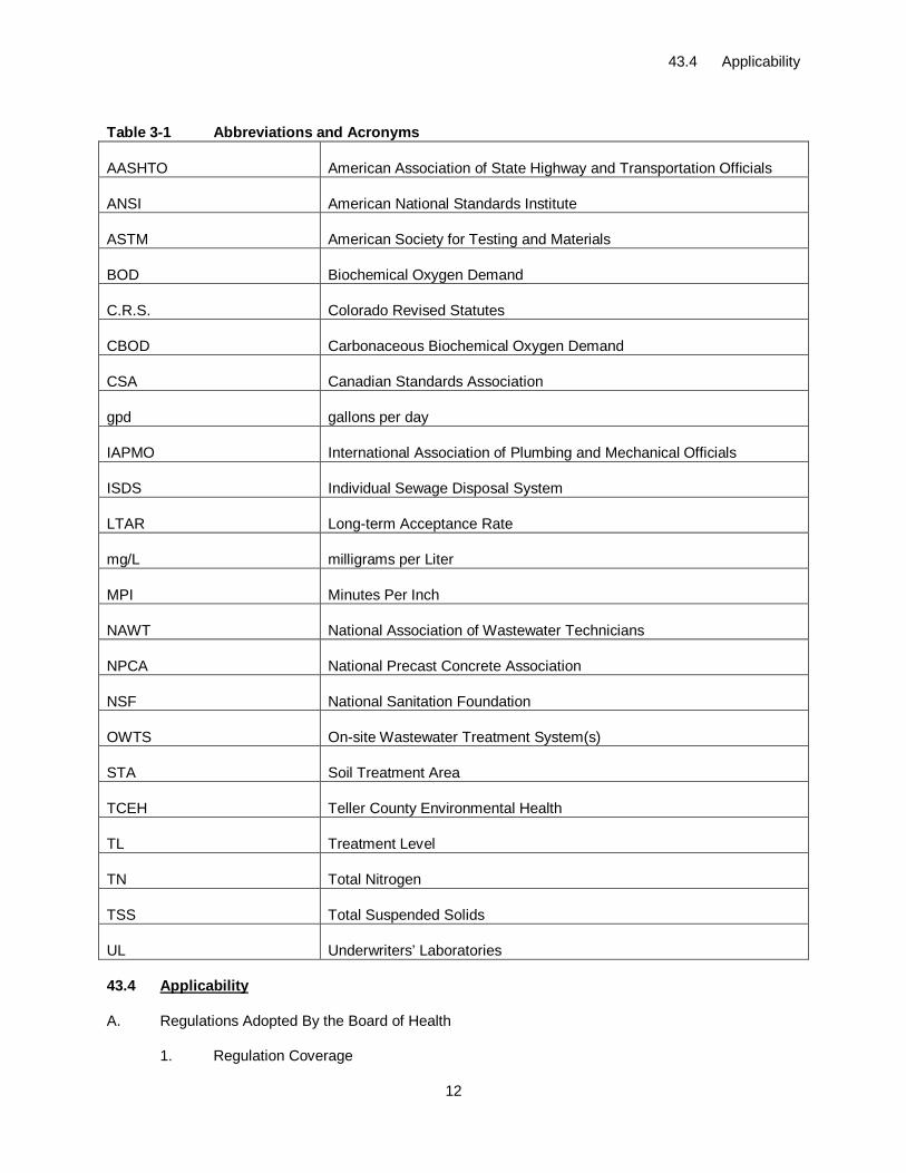
Table 3-1 Abbreviations and Acronyms
AASHTO American Association of State Highway and Transportation Officials
ANSI American National Standards Institute
ASTM American Society for Testing and Materials
BOD Biochemical Oxygen Demand
C.R.S. Colorado Revised Statutes
CBOD Carbonaceous Biochemical Oxygen Demand
CSA Canadian Standards Association
gpd gallons per day
IAPMO International Association of Plumbing and Mechanical Officials
ISDS Individual Sewage Disposal System
LTAR Long-term Acceptance Rate
mg/L milligrams per Liter
MPI Minutes Per Inch
NAWT National Association of Wastewater Technicians
NPCA National Precast Concrete Association
NSF National Sanitation Foundation
OWTS On-site Wastewater Treatment System(s)
STA Soil Treatment Area
TCEH Teller County Environmental Health
TL Treatment Level
TN Total Nitrogen
TSS Total Suspended Solids
UL Underwriters’ Laboratories
43.4 Applicability
A. Regulations Adopted By the Board of Health
1. Regulation Coverage
43.4 Applicability
13
a. An OWTS with design capacity less than 2,000 gpd must comply with regulations adopted by the board of health pursuant to this regulation and the OWTS Act. Within the jurisdiction of the TCEH agency, the regulations promulgated by the board of health govern all aspects of OWTS permits, performance, location, construction, alteration, installation, and use.
b. An OWTS with design capacity equal to or greater than 2,000 gpd must comply with this regulation, site location and design approval in section 25-8-702, C.R.S., and the discharge permit requirements in the Water Quality Control Act, 25-8-501, et seq. C.R.S.
(1) Applicable Commission regulations include, but are not limited to, the following:
(i) Regulation 22 - Site Location and Design Approval Regulations for Domestic Wastewater Treatment Works (5 CCR 1002-22).
(ii) Regulation 41 - The Basic Standards for Ground Water (5 CCR 1002-41).
(iii) Regulation 42 - Site-Specific Water Quality Classifications and Standards for Ground Water (5 CCR 1002-42).
(iv) Regulation 61 - Colorado Discharge Permit System Regulations (5 CCR 1002-61).
(v) Regulation 62 - Regulations for Effluent Limitations (5 CCR 1002-62).
(2) For systems equal to or greater than 2,000 gpd, the Division is also authorized to determine those parts of this regulation identified as the prerogative of the TCEH agency.
(3) The requirements for maintenance and standards of performance for systems equal to or greater than 2,000 gpd shall be determined by the site application approval and discharge permit.
(4) In the interest of facilitating communication of TCEH concerns regarding a design being reviewed by the Division, the TCEH agency can provide comments to the Division for consideration during the Division’s review of the proposed design and discharge permit application. Under such a coordinated process, the Division retains final authority for approval or denial of each domestic wastewater treatment works that is regulated under the site location approval and Colorado Discharge Permit System regulations. Prior to approval or denial of each OWTS domestic wastewater treatment works, the Division shall acknowledge and consider Teller County OWTS regulations when they are more stringent and restrictive than this regulation.
B. Permit Application Requirements and Procedures
1. Prior to installing, altering, or repairing a system, the applicant must obtain a permit from the TCEH agency.
43.4 Applicability
14
2. An applicant must submit a complete application that is consistent with section 4.B.3. to the TCEH agency prior to installing, altering or repairing a system.
3. Minimum Permit Application Requirements:
a. Owner name and contact information;
b. Property address;
c. Property legal description;
d. Type of permit;
e. Report from Site and Soil Evaluation (section 5);
f. System design with a legible, accurate site plan which shows pertinent physical features on subject property, and on adjacent properties, as noted in Table 7-1; and
g. Other information, data, plans, specifications and tests as required by the TCEH agency.
(1) When specific evidence suggests undesirable soil conditions exist, additional hydrological, geological, engineering or other information provided by a professional engineer or geologist may be required to be submitted by the applicant. This requirement shall not prejudice the right of the TCEH agency to develop its own information from its own source at its own expense.
4. Permit Fees, see Appendix A1
a. The board of health hereby adopts the fees set forth on Appendix A1, and may set other fees for permits. The permit fees may be no greater than required to offset the actual indirect and direct costs of the local public health agency. 25-10-107, C.R.S.
b. Permit application fees must not exceed the maximum fees established in section 25-10-107, C.R.S. Permit application fees must be submitted by an applicant with the permit application, and are due and payable upon receipt of the permit application.
c. The board of health may make provision for the waiver of any permit fee normally required for an OWTS.
5. Other Fees, see Appendix A1
a. The board of health hereby adopts the fees set forth on Appendix A1, and may set other fees for inspections, percolation tests, soil evaluation, and other services performed by the TCEH agency. The fees shall be no greater than required to offset the actual indirect and direct costs of the services, and shall not exceed the maximum amounts specified in section 25-10-107, C.R.S.
b. Surcharge - The TCEH agency must collect a fee of twenty-three dollars for each permit issued for a new, repaired, or upgraded OWTS. Of that fee, the TCEH agency shall retain three dollars to cover the agency’s administrative costs
43.4 Applicability
15
and twenty dollars shall be transmitted to the state treasurer, who shall deposit that sum in the water quality control fund created in section 25-8-502(1)(c), C.R.S.
6. Permit Term
a. An OWTS permit expires one year after the date of issuance if construction has not commenced or as specified by board of health regulations.
b. Any change in plans or specifications of the OWTS after the permit has been issued invalidates the permit unless the permittee receives written approval from the TCEH agency for such changes.
7. Repair Permit
a. The owner or occupant of a property on which an OWTS is not in compliance must obtain a repair permit from the TCEH agency. The applicant must apply for a repair permit within two business days after receiving notice from the TCEH agency that the system is not functioning in compliance with the OWTS Act or applicable regulations, or otherwise constitutes a nuisance or a hazard to public health or water quality.
b. The repair permit must provide for a reasonable period of time within which the owner or occupant must make repairs. At the end of that period, the TCEH agency must inspect the system to ensure it is functioning properly. Concurrently with the issuance of a repair permit, the TCEH agency may issue an emergency use permit authorizing continued use of a malfunctioning system on an emergency basis for a period not to exceed the period stated in the repair permit. Such an emergency use permit may be extended, for good cause shown, in the event repairs may not be completed in the period stated in the repair permit through no fault of the owner or occupant and only if the owner or occupant will continue to make repairs to the system.
8. A permit shall be required for the expanded use of an OWTS. The OWTS must be replaced or modified to handle the increased design flow unless it is determined that the existing system is adequately designed and constructed for the higher design flow rate.
9. These regulations include provisions that provide for review by the board of health of applications denied by the TCEH agency when requested by an applicant.
10. The issuance of a permit and specifications of terms and conditions therein shall not constitute assumption of liability, nor create a presumption that the TCEH agency or its employees may be liable for the failure or malfunctioning of any system. Permit issuance shall not constitute a certification that the system, the equipment used in the system, or any component used for system operation will ensure continuous compliance with the provision of the OWTS Act, the regulations adopted thereunder, or any terms and conditions of a permit.
11. No OWTS permit shall be issued to any person when the subject property is located within 1000’ of a municipality or special district that provides public sewer service, except where such sewer service to the property is not feasible in the determination of the municipality or special district, or the permit is otherwise authorized by the municipality or special district.
43.4 Applicability
16
12. The TCEH agency may consider a permit to be issued for the installation of a septic system and dwelling or structure on separate parcels in the Ute Lakes Environmental Health Overlay Zone in accordance with Appendix B1.
C. Determination
1. The TCEH agency must determine whether the information provided in the permit application, site and soil evaluations, assumptions and calculations, and design of the proposed OWTS are in compliance with the requirements of the OWTS Act and regulations adopted pursuant thereto. If the submittal is determined to be in compliance, authorization to begin installation may be given.
D. Access to Site
1. For the purpose of inspecting and enforcing applicable regulations and the terms and conditions of any permit issued and investigating and responding to complaints, the TCEH agency is authorized to enter upon private property at reasonable times and upon reasonable notice for the purpose of determining whether or not an operating OWTS is functioning in compliance with the OWTS Act and applicable regulations adopted pursuant thereto and the terms and conditions of any permit issued and to inspect and conduct tests in evaluating any permit application. The owner or occupant of every property having an OWTS must permit the TCEH agency access to the property to make inspections, conduct required tests, take samples, and monitor compliance.
E. Inspection Stages
1. These regulations specify the stages of site evaluation, construction, installation, alteration, or repair at which the TCEH agency shall require inspections.
2. Before a system is placed in use, the owner, the owner's agent or the systems contractor must provide the TCEH agency and the engineer, if engineer-designed, with notice that the progress of the work has been sufficiently completed to allow inspections to determine if all work has been performed in accordance with the permit requirements and to determine compliance of the system with the OWTS Act and the regulations adopted thereunder.
F. Final approval of the permit by the TCEH agency must include, but is not limited to:
1. Receipt of letter from the engineer certifying construction of system as designed, if engineer-designed;
2. Receipt of as-built drawing;
3. Final inspection prior to backfilling system by the TCEH agency confirming that the OWTS was installed according to the permit requirements and regulations or variances to the regulations; and
4. Identification of system contractor.
G. Division Authority to Administer and Enforce
1. Wherever the term board of health or TCEH agency is used in this regulation, said terms shall also include the Division under its designated authority for the purposes of administering and enforcing the provisions of this regulation where necessary to protect the public health and environment.
43.4 Applicability
17
H. Primary Enforcement Responsibility
1. The primary responsibility for enforcement of the provisions of the OWTS Act and the regulations adopted under said article shall lie with the board of health.
2. In the event that the board of health fails to administer and enforce the provisions of said section and the regulations adopted under the OWTS Act, the Division may assume such functions of the TCEH agency or board of health as may be necessary to protect the public health and environment. 25-10-110, C.R.S.
I. Product Development Permit
1. The TCEH agency may issue a product development permit for a proprietary treatment component or series of components. Requirements for proprietary treatment component acceptance are in section 13.D. It must be shown that a complete system, meeting the requirements of this regulation and the site, can be installed in the event the proprietary treatment component or sequence fails to perform. The product under development may then be added to the treatment system, allowing the product developer to gather data about the product’s performance in the field.
2. Before a product development permit is issued, the Division must determine that the product to be tested qualifies for testing under the product development evaluation based on information submitted to the Division.
3. A completed application for a product development permit must be submitted to the TCEH agency at least 30 days in advance of installation of the product.
4. An application for a product development permit must include the following:
a. Proof of the ability to install a replacement OWTS in compliance with all Teller County requirements in a timely manner in the event of a failure or malfunction of the system under testing;
b. A description of the product under development including performance goals; and
c. Documentation signed by the owner of the proposed product development site allowing access to the TCEH agency and Division for inspection of the site.
5. The TCEH agency may stipulate additional requirements for the product development permit necessary to assure the performance of the OWTS.
6. A product development permit is a site-specific permit. Product development testing at multiple sites requires a product development permit for each site.
7. During the term of the product development permit, all data collected is to be submitted to the Division and the TCEH agency.
8. The TCEH agency may revoke or amend a product development permit, if the continued operation or presence of the product under development:
a. Presents a risk to the public health or environment;
b. Causes adverse effects on the proper function of the OWTS on the site;
43.4 Applicability
18
c. Leaks or discharges effluent on the surface of the ground; or
d. If the developer of the product fails to comply with any requirements stipulated on the permit by the TCEH agency or the Division.
9. If the product development permit is revoked, the product developer must install the replacement system.
J. Experimental Systems
1. Except for designs or types of systems which have been approved by the Division pursuant to section 25-10-108 (1), C.R.S., the board of health may approve an application for a type of system not otherwise provided for in this regulation only if the system has been designed by a professional engineer, and only if the application provides proof of the ability to install a replacement OWTS in compliance with all Teller County requirements in a timely manner in the event of a failure or malfunction of the experimental system.
2. The board of health shall not arbitrarily deny any person the right to consideration of an application for such a system and shall apply reasonable performance standards in determining whether to approve such an application. 25-10-108 (2), C.R.S.
K. Prohibition of OWTS in Unsuitable Areas
1. The board of health may prohibit issuance of OWTS permits in accordance with applicable land use laws and procedures for defined areas in which the board of health determines that construction and use of additional OWTS may constitute a hazard to public health or water quality.
L. Licensing of Systems Contractors and Systems Cleaners
1. The board of health may adopt regulations which provide for the licensing of systems contractors. A fee not to exceed actual TCEH agency costs may be charged by the TCEH agency for the initial license of a systems contractor; a fee not to exceed actual costs may be charged by the TCEH agency for a renewal of the license. Initial licensing and renewals thereof shall be for a period of not less than one year. Renewals may be scheduled to coincide with the calendar year.
2. The board of health may revoke the license of a systems contractor for violation of the applicable provisions of the OWTS Act and the implementing regulations or for other good cause shown, after a hearing conducted upon reasonable notice to the systems contractor and at which the systems contractor may be present, with counsel, and be heard.
3. The board of health may adopt regulations which provide for the licensing of systems cleaners. A fee not to exceed actual costs may be charged by the TCEH agency for the initial license of a systems cleaner; a fee not to exceed actual costs may be charged for the renewal of the license. Initial licensing and renewals thereof shall be for a period of not less than one year. Renewals may be scheduled to coincide with the calendar year.
4. The board of health may suspend or revoke the license of a systems cleaner for violation of the applicable provisions of the OWTS Act and the regulations adopted under said section or for other good cause shown after a hearing conducted upon reasonable notice to the systems cleaner and at which the systems cleaner may be present, with counsel, and be heard. 25-10-109, C.R.S.
43.4 Applicability
19
M. Variance Procedure
1. General
a. The purpose of this section is to provide a procedure for TCEH to consider variances from the design and/or sitting requirements of the OWTS regulations.
b. The fee for processing an OWTS permit with a variance shall be the standard OWTS permit fee.
2. Requirements for Variance Consideration
a. The applicant must submit an application for a variance along with the appropriate fees and other required document defined in this regulation. This application must be on the form provided by the TCEH agency and submitted to the TCEH agency within 60 days of receipt of the denial.
b. Where the board of health adopts a variance procedure, the board must hear the variance request.
c. All variances will require public hearings. Prior to the rendering a decision on a variance request requiring a public hearing, a public hearing must be held. The hearing must be the subject of a public notice or notice must be sent via certified mail, with a minimum 20-day reply time from the date of mailing, to all adjacent property owners.
d. Variance requests must be accompanied by:
(1) Site-specific request identifying the specific criteria from which a variance is being requested;
(2) Technical justification by a professional engineer or professional geologist, which indicates the specific conditions which exist and/or the measures which will be taken that support a finding that the variance will result in no greater risk than that associated with compliance with the requirements of the regulation. Examples of conditions which exist, or measures which might be taken, include but are not limited to the following: evidence of a natural or manmade physical barrier to the movement of effluent to or toward the feature from which the variance is requested; placement of a manmade physical barrier to the movement of effluent to or toward the feature from which the variance is requested; soil replacement with sand filter media to reduce the infiltration rate of the effluent such that the travel time of the effluent from the absorption field to the physical feature is no less than the travel time through the native soils at the prescribed setback and Treatment Level 2;
(3) A discussion of alternatives considered in lieu of the requested variance;
(4) Technical documentation for selected alternative, which may include a testing program, which confirms that the variance does not increase the risk to public health and to the environment; and
(5) A statement of the hardship that creates the necessity for the variance.
43.4 Applicability
20
e. The applicant has the burden of proof to demonstrate that the variance is justified and will pose no greater risk to public health and the environment than would a system meeting the regulations.
3. The board of health has the authority to impose site-specific requirements and conditions on any variance granted.
4. Outcome of the Variance Proceeding
a. The applicant must be notified, in writing, of the board of health’s decision regarding the request for a variance. The notice of a denial of a variance must include those reasons which form the basis for the denial. The notice of an approval of a variance must include any conditions of the approval. The variance, and any conditions thereof, must be recorded on the deed to the property and any expenses associated with that recording must be the responsibility of the party obtaining the variance.
5. Prohibitions on the Granting of Variance Requests
a. No variance shall be issued where the property can accommodate a conforming OWTS.
b. No variance shall be issued to mitigate an error in construction involving any element of property improvements.
c. No variance shall be allowed solely for economic gain.
d. No variance shall be issued, if it will result in a setback reduction to an offsite physical feature that does not conform to the minimum setbacks defined in Table 7-1 of this regulation without the written consent of the owner of property containing said feature. Property lines are considered offsite features.
e. No variance shall be issued, if it reduces the separation to ground water or bedrock based on the level of treatment in Table 7-2.
f. No variance from the horizontal setback from a well shall be issued unless it also meets the variance requirements of the Board of Examiners of Water Well Construction and Pump Installation Contractors.
6. Variances for Repair of Failing Systems
a. When a proposed variance for a system repair or upgrade would result in encroachment on minimum distances to physical features on neighboring properties required by the Division, the hearing procedures in 4.O.2, Requirements for Variance Consideration above must be followed.
b. For the repair of or upgrade to an approved existing system where the existing system does not meet the required separation distances and where the size of the lot precludes adherence to the required distances, a variance to the separation distances may be requested. The repairs or upgrade shall be no closer to features requiring setbacks than the existing facilities. Variances requesting setbacks no closer than existing setbacks do not have to provide technical justification from a professional engineer or professional geologist.
7. Findings on Appeal
43.4 Applicability
21
a. A request for review must be made within 60 days after denial of an application by the TCEH agency.
b. The applicant must bear the burden of supplying the board of health with sufficient evidence to document that the denied system shall be constructed and used in such a manner that will result in no greater risk than that associated with compliance with the requirements of the regulation, comply with the declaration and intent of this regulation, and comply with all applicable state and local regulations and required terms and conditions in any permit.
c. Such review must be conducted pursuant to the requirements of section 24-4-105, C.R.S.
N. General Prohibitions; Section 25-10-112, C.R.S.
1. The County shall not issue to any person:
a. A permit to construct or remodel a building or structure that is not serviced by a sewage treatment works until the TCEH agency has issued a permit for an OWTS.
b. An occupancy permit for the use of a building that is not serviced by a sewage treatment works until the TCEH agency makes a final inspection of the OWTS, provided for in section 25-10-106 (1) (h), C.R.S. and the TCEH agency approves the installation.
2. Construction of new cesspools is prohibited.
3. A person must not connect more than one dwelling, commercial, business, institutional or industrial unit to the same OWTS unless such multiple connection was specified in the application submitted and in the permit issued for the system.
4. No person shall construct or maintain any dwelling or other occupied structure which is not equipped with adequate facilities for the sanitary disposal of sewage.
5. All persons shall dispose of septage removed from systems in the process of maintenance or cleaning at an approved site and in an approved manner.
O. Cease and Desist Orders
1. The TCEH agency may issue an order to cease and desist from the use of any OWTS or sewage treatment works which is found by the health officer not to be functioning in compliance with the OWTS Act or with applicable regulations or is found to constitute a hazard to public health, or has not otherwise received timely repairs under the provisions of section 25-10-106 (1) (j), C.R.S. Such an order may be issued only after a hearing which shall be conducted by the health officer not less than 48 hours after written notice thereof is given to the owner or occupant of the property on which the system is located. The order shall require that the owner or occupant bring the system into compliance or eliminate the health hazard within a reasonable period of time, or thereafter cease and desist from the use of the system. A cease and desist order issued by the health officer shall be reviewable in the district court for Teller County wherein the system is located and upon a petition filed not later than ten days after the order is issued.
P. Penalties; Section 25-10-113, C.R.S.
43.5 Site and Soil Evaluation
22
1. Any person who commits any of the following acts or violates any of the provisions of this regulation commits a Class 1 petty offense as defined in section 18-1-107, C.R.S.:
a. Constructs, alters, installs, or permits the use of any OWTS without first having applied for and received a permit as provided for in section 25-10-106, C.R.S.;
b. Constructs, alters, or installs an OWTS in a manner which involves a knowing and material variation from the terms or specifications contained in the application, permit or variance;
c. Violates the terms of a cease and desist order that has become final under the terms of section 25-10-106 (1) (k), C.R.S.;
d. Conducts a business as a systems contractor without having obtained the license provided for in section 25-10-109 (1), C.R.S., in areas which the board of health has adopted licensing regulations pursuant to that section;
e. Conducts a business as a systems cleaner without having obtained the license provided for in section 25-10-109 (2), C.R.S., in areas which the board of health has adopted licensing regulations pursuant to that section;
f. Falsifies or maintains improper records concerning system cleaning activities not performed or performed improperly; or
g. Willfully fails to submit proof of proper maintenance and cleaning of a system as required by regulations adopted by the board of health.
43.5 Site and Soil Evaluation
A. A site and soil evaluation must be conducted for each property on which an OWTS is proposed, to determine the suitability of a location to support an OWTS, and to provide the designer a sound basis to select the most appropriate OWTS design for the location and application.
1. Each site evaluation shall consist of:
a. Preliminary investigation;
b. Reconnaissance;
c. Detailed soil investigation; and
d. Report and site plan.
B. A preliminary investigation shall review documented information relative to the site and anticipated conditions. Information gathered as part of the preliminary investigation shall include, but is not limited to:
1. Property Information:
a. Address;
b. Legal description;
c. Existing structures; and
43.5 Site and Soil Evaluation
23
d. Location of existing or proposed wells on the property.
2. TCEH agency records.
3. Published site information:
a. Topography; and
b. Soil data.
4. Location of physical features, on and off the property that will require setbacks as identified in Table 7-1.
5. Preliminary soil treatment area size estimate based on information on existing or planned facility and Teller County regulations.
6. Other information required by TCEH agency.
7. Additional information that may be useful to the specific evaluation as available:
a. Survey;
b. Easements;
c. Floodplain maps;
d. Geology and basin maps and descriptions;
e. Aerial photographs;
f. Climate information; and
g. Delineated wetlands maps.
C. A reconnaissance visit to the property shall evaluate the topography and other surface conditions that will impact the selection and location and design of the OWTS, including:
1. Landscape position;
2. Topography;
3. Vegetation;
4. Natural and cultural features; and
5. Current and historic land use.
D. Detailed Soil Investigation
1. Soil investigations to determine the long-term acceptance rate of a soil treatment area shall be either:
a. Visual and tactile evaluation of two or more soil profile test pit excavations; or
43.5 Site and Soil Evaluation
24
b. Percolation tests plus one or more soil profile holes or one or more soil profile test pit excavations.
2. If percolation tests are performed, at least one soil profile hole shall be evaluated to determine whether current ground water levels and/or bedrock is encountered within 8 feet of the ground surface. A visual and tactile evaluation of a soil profile test pit excavation as described in section 5.D.5. may be substituted for a profile hole. Following three years after the effective date of this regulation, a visual and tactile evaluation of a soil profile test pit excavation shall be used instead of a soil profile hole when percolation tests are performed to determine long-term acceptance rates.
3. If visual and tactile evaluations of soil are performed without percolation tests to determine a long-term acceptance rate:
a. Evaluation of two or more soil profile test pit excavations must be performed to determine soil types and structure, restrictive layers, evidence of seasonal high ground water, and best depth for the infiltrative surface.
b. At least one of the soil profile test pit excavations must be performed in the portion of the soil treatment area anticipated to have the most limiting conditions.
c. The total number of soil profile test pit excavations required is based on the judgment of the competent technician.
4. Procedure for performing percolation tests:
a. The percolation testing shall be performed by a trained person under the supervision of a professional engineer or by a competent technician.
b. Location
(1) Soil percolation tests shall be performed in at least three test holes in the area in which the soil treatment area is to be located, spaced reasonably evenly over the proposed area. There shall be no less than one test hole provided in every 1,200 square foot area of soil treatment area.
(2) If the likely depth of a proposed infiltrative surface is uncertain, percolation tests shall be performed at more than one depth to determine the depth of the infiltrative surface.
c. Dimensions
(1) The percolation test hole shall have a diameter of eight to 12 inches and be terminated a minimum of six inches and a maximum of 18 inches below the proposed infiltrative surface.
d. Change in Soil
(1) If a change of soil type, color or structure is present within those soils comprising the depth of soil below the infiltrative surface as required in Table 7-2 for vertical separation, a minimum of two soil percolation holes shall be terminated in the changed soil, and percolation tests shall be conducted in both holes.
e. Percolation Tests
43.5 Site and Soil Evaluation
25
(1) The percolation tests shall be conducted using the hole preparation, soil saturation and rate measurement procedures described below.
(2) Preparation of Percolation Test Holes
(i) Excavate the hole to the depth and diameter required.
(ii) Carefully scrape the bottom and sides of the hole with a knife blade or sharp instrument to remove any smeared soil surfaces and provide a natural soil interface into which water may percolate.
(iii) Remove all loose soil from the hole.
(iv) Add two inches of very coarse sand or fine gravel to protect the bottom of the hole from scouring and sediment.
(3) Presoak
(i) The hole shall be presoaked adequately to accomplish both saturation, which is filling the void spaces between the soil particles, and swelling, which is the intrusion of water into the individual soil particles.
(ii) To presoak the hole, carefully fill the hole with clean water to a minimum depth of 12 inches over the gravel placed in the bottom of the hole. In most soils, it is necessary to refill the hole by supplying a surplus reservoir of clean water, possibly by means of an automatic siphon, to maintain water in the hole for at least four hours and preferably over night. Determine the percolation rate 24 hours after water is first added to the hole. This procedure is to ensure that the soil is given ample time to swell and to approach the condition it will be in during the wettest season of the year. In sandy soils containing five percent or less particles passing the #200 sieve, by weight, the swelling procedure is not essential and the test may be conducted after the water from one filling of the hole has completely seeped out of the hole.
(4) Percolation Rate Measurement
(i) With the exception of sandy soils containing five percent or less particles passing the #200 sieve, by weight, percolation rate measurements shall be made on the day following the presoak procedure.
(ii) If water remains in the percolation test hole after the swelling period, adjust the depth to approximately six inches above the gravel in the bottom of the hole. From a fixed reference point, measure the drop in water level over a series of 30 minute intervals. The drops are used to calculate the percolation rate.
(iii) If no water remains in the hole after the swelling period, carefully add clean water to bring the depth of water in the hole to approximately six inches above the top of the gravel in the
43.5 Site and Soil Evaluation
26
bottom of the hole. From a fixed reference point, measure the drop in water level at 30 minute intervals for four hours, refilling to six inches over the top of the gravel as necessary. The drop in water level that occurs during the final 30-minute period is used to calculate the percolation rate. If the water level drops during prior periods provide sufficient information, the procedure may be modified to suit local circumstances. The requirement to conduct a four hour test under this section is waived if three successive water-level drops do not vary by more than 1/16 inch; however, in no case shall a test under this section be less than two hours in duration.
(5) Sandy Soils
(i) In sandy soils or other soils in which the first six inches of water seeps out of the hole in less than 30 minutes, after the 24 hours swelling period, the time interval between measurements shall be taken as ten minutes and the test conducted for one hour. The drop that occurs during the final ten minutes shall be used to calculate the percolation rate.
(ii) If the soil is so sandy or coarse-textured that it will not retain any water, then the infiltration rate shall be recorded as less than one minute per inch.
(6) Special Soil Types
(i) TCEH agency may identify soil types in its area, for which it shall require different procedures such as extra presoaking to obtain a valid percolation rate.
(7) Percolation Rate Determination and Reporting
(i) The field percolation rate shall be the average rate of the percolation rates determined for all percolation test holes observed in the proposed soil treatment area in minutes per inch. The average percolation rate determined by the tests shall be used in determining the long-term acceptance rate for the proposed system from Table 10-1.
(ii) The technician performing the percolation tests shall furnish an accurate scale drawing, showing the location of the soil profile holes or soil profile test pit excavations and percolation holes tied to lot corners or other permanent objects. The drawing shall meet the criteria in section 5.F.1.g. The information in the subsections following section 5.F.1.g.(1) through 5.F.1.g.(5). may be included but is not required for this drawing. All holes shall be clearly labeled to relate to the information provided for the profile test pits and percolation tests.
(8) Percolation Test Waiver
(i) If the applicant demonstrates to the satisfaction of the TCEH agency that the system is not dependent upon soil absorption, the requirement of percolation tests may be waived.
43.5 Site and Soil Evaluation
27
(9) Alternate Percolation Testing
(i) Alternate percolation test procedures may be approved, provided the test results of alternate procedures are substantially equivalent to those determined using the test procedures described in this section.
(ii) Prior approval from the TCEH agency of alternate percolation test procedures is required.
5. Visual and tactile evaluation of soil requirements:
a. Each soil profile test pit excavation observed at the proposed soil treatment area must be evaluated under adequate light conditions with the soil in an unfrozen state.
b. The soil observations must be conducted at or immediately adjacent to the location of the proposed soil treatment area, but if possible, not under the final location of a trench or bed.
c. The soil observation method must allow observation of the different soil horizons that constitute the soil profile.
d. Soil profile test pit observations must be conducted prior to percolation tests to determine whether the soils are suitable to warrant percolation tests and, if suitable, at what depth percolation tests shall be conducted.
e. The minimum depth of the soil profile test pit excavation must be to the periodically saturated layer, to the bedrock, or four feet below the proposed depth of the infiltrative surface, whichever is encountered first.
f. The soil type at the proposed infiltrative surface of the soil treatment area or a more restrictive soil type within the treatment depth shall be used to determine the long-term acceptance rate from Table 10-1. The treatment depth is two to four feet depending on the required thickness for the treatment level below the infiltrative surface from Item 4, Table 7-2.
g. Soils data, previously collected by others at the site can be used for the purposes of an OWTS design at the discretion of the TCEH agency. It is recommended that the data be verified, at a minimum, by performing an evaluation of a soil profile test pit excavation.
6. Soil descriptions for determination of a limiting layer shall include:
a. The depth of each soil horizon measured from the ground surface and a description of the soil texture, structure, and consistency of each soil horizon;
b. Depth to the bedrock;
c. Depth to the periodically saturated soil as determined by:
(1) Redoximorphic features and other indicators of water levels, or
43.5 Site and Soil Evaluation
28
(2) Depth of standing water in the soil observation excavation, measured from the ground surface, if observed, unless redoximorphic features indicate a higher level; and
d. Any other soil characteristic that needs to be described to design a system, such as layers that will restrict permeability.
E. Percolation Holes, Profile Holes, and Profile Test Pits Excavations – Marking
1. The engineer or technician conducting the percolation tests must, upon completion of the tests, flag or otherwise mark each hole to allow easy location by others. Percolation holes and profile test pits must remain open until after evaluation by the TCEH agency, if required by the agency.
F. Report and Site Plan
1. A written report shall describe the results of the preliminary investigation, reconnaissance, and detailed evaluations. The report may be in text and/or tabular form and shall include a drawing locating features relative to the proposed OWTS location and test locations. The report may be included as part of the OWTS design document. The report must include, but is not limited to:
a. The name, address, telephone number, e-mail address, and credentials and qualifications of the individual conducting the site evaluation;
b. Preliminary and detailed evaluations, providing information from the surface site characteristics assessment and soils investigation;
c. Dates of preliminary and detailed evaluations;
d. A graphic soil log, to scale, indicating depth of drill hole or excavation, soil description and classification, depth to ground water encountered during drilling or excavation, type of equipment used to drill the profile hole or excavate the soil profile test pit, date of soils investigation, name of investigator and company name.
e. Setback distances to features listed in Table 7-1;
f. Setback distances to features listed in Table 7-2, existing on the site or within applicable setback limits, whichever is greater;
g. A drawing created to a scale that provides the complete property boundary lines. Minimum drawing size shall be 8.5-inches by 11-inches. If the property is too large to adequately indicate and label the profile test pits and percolation test holes, a detail of the portion of the site containing the soil profile test pits and percolation test holes must be submitted. If the property is too large to adequately show site evaluation information, a detail drawing that includes the information required from the site and soil evaluation that will impact the location of the OWTS must be submitted. Drawings shall indicate dimensions, have a north arrow and graphic scale and include:
(1) Horizontal and vertical reference points of the proposed soil treatment area; soil observations; percolation testing results and pertinent distances from the proposed OWTS to all required setbacks, lot improvements, easements; ordinary high water mark of a pond, creek,
43.5 Site and Soil Evaluation
29
stream, lake, wetland or other surface waters, and detention or retention ponds; and property lines;
(2) Contours or slope direction and percent slope;
(3) The location of any visible or known unsuitable, disturbed or compacted soils;
(4) The estimated depth of periodically saturated soils and bedrock, or flood elevation, if applicable; and
(5) The proposed elevation of the infiltrative surface of the soil treatment area, from an established datum (either ground surface or a benchmark);
h. Anticipated construction-related issues;
i. An assessment of how known or reasonably foreseeable land use changes are expected to affect the system performance, including, but not limited to, changes in drainage patterns, increased impervious surfaces and proximity of new water supply wells; and
j. A narrative explaining difficulties encountered during the site evaluation, including but not limited to identifying and interpreting soil and landform features and how the difficulties were resolved.
G. Design Document
1. The report and site plan may be attached to the design document or the report and site plan may be combined with the design information as a single document.
2. The design document shall include a brief description of the facility and its proposed use, basis and calculations of design flow, and influent strength.
3. The design document must contain all plan detail necessary for permitting, installation and maintenance, including:
a. Assumptions and calculations for each component;
b. A scale drawing showing location of each OWTS component and distances to water, physical and health impact features requiring setbacks;
c. Layout of soil treatment area, dimensions of trenches or beds, distribution method and equipment, distribution boxes, drop boxes, valves, or other components used;
d. Depth of infiltrative surface of soil treatment area, depth of the septic tank, depth of other components from the original and finished ground surface;
e. Specifications of each component. Specifications for septic tanks or other buried components must include loads due to burial depth, additional weight or pressure loads, and highest elevation of ground water. Resistance to local water composition such as high sulfates shall be included in the specification if such conditions exist at the site;
f. References to design manuals or other technical materials used;
43.5 Site and Soil Evaluation
30
g. Installation procedures;
h. Operation and maintenance manuals or instructions; and
i. Other information that may be useful such as photos and cross-section drawings.
H. As-Built Drawings: Scale drawing showing the OWTS as installed, including its location from known and findable points, dimensions, depths, sizes, manufacturers’ names and models as available, and other information relative to locating and maintaining the OWTS components.
I. Site protection: During construction, the proposed soil treatment area and replacement area, if any, must be protected from disturbance, compaction, or other damage by staking, fencing, posting, or other effective method.
J. Qualifications for a Competent Technician
1. Percolation Tests
a. Competencies needed:
(1) Set up equipment;
(2) Perform and run percolation tests according to the procedure in this regulation; and
(3) Record results and calculate percolation rates.
b. TCEH agency may approve training for percolation testing.
2. Visual and Tactile Evaluation of Soil
a. Competencies needed:
(1) Identify soil types by hand texturing and observation;
(2) Identify presence or absence of soil structure;
(3) Identify grade of soil structure;
(4) Recognize evidence of highest seasonal water surface;
(5) Identify layers and interfaces that will interfere with effluent movement;
(6) Determine the most promising depth for infiltrative surface of OWTS and for percolation tests, if used; and
(7) Understand basic principles of OWTS siting and design.
b. Possible demonstrations of competence in visual and tactile evaluation of soil:
(1) Degree in soil science, agronomy, geology, other majors if a course(s) in soil morphology was included; or
(2) Attendance at training or workshop for soil evaluation for OWTS including both class and field work.

43.6 Wastewater Flow and Strength
31
c. The Division shall approve training for visual and tactile evaluation of soil.
43.6 Wastewater Flow and Strength
A. Wastewater Flows
1. The Board of Health may, by further adopted regulations, require the installation of a meter to measure flow into the facility or the OWTS.
2. Single-Family Residential Homes:
a. Design flow per person shall be 75 gallons per day (gpd).
b. The board of health may increase the wastewater design flow per person to 100 gpd where justified.
c. The minimum design flow for a new home shall be for a two-bedroom house. The minimum design flow for the repair or replacement of an OWTS of an existing one-bedroom home shall be one-bedroom unless bedrooms are added.
d.
e. d. The assumed number of persons per bedroom in all situations shall be two for design purposes.
3. Auxiliary Buildings
a. If a single-family home has an auxiliary building, such as a non-commercial shop with plumbing fixtures, the flow may be conveyed to the OWTS of the home, or to a separate OWTS constructed to handle the flow from the auxiliary facility.
b. If the flow from the auxiliary building is only generated by residents of the home, it shall be assumed that the OWTS for the home will be adequately sized to include the auxiliary building if the flows are combined.
c. If the auxiliary building will have users in addition to residents and the flow from the auxiliary building will flow to the OWTS of the home, the design flow of the home must include the increased use.
d. If the auxiliary building has a separate OWTS, the facility shall be sized on the basis of Table 6-2 and a septic tank detention time of 48 hours.
4. Multi-Family and Commercial On-site Wastewater Treatment Systems
a. Design flow values and strengths for multi-family and commercial systems shall be determined from:
(1) Table 6-2; or
(2) An analysis of flows and strengths from at least three comparable facilities or from the facility, if it is an existing facility, must be submitted to the TCEH agency for approval. The analysis shall include:
43.6 Wastewater Flow and Strength
32
(i) Metered water flows for inside use only for at least a year, or if use is seasonal, for a full season. If metered flows are less than full capacity, they shall be paired with actual use in units of persons present or meals served or other units as appropriate so that an actual daily rate per unit can be determined. The daily rate per unit times the number of units at full occupancy shall be the design flow.
(ii) Total Suspended Solids and BOD5 or CBOD5 tests at times of full use. At least three samples taken at least one week apart are required.
(iii) Explanation and justification for the comparability of the tested facilities with the proposed facility.
5. Flow Equalization
a. Flow equalization may be used if a facility has flows that vary from day to day by more than four times the average flow.
b. The highest peak assumed shall be at least equal to the full capacity of the facility.
c. The stored flow shall be distributed to the soil treatment area before the next greater-than-average peak.
d. Flow equalization may be used only if:
(1) The facility is non-residential;
(2) The facility is only used for one purpose;
(3) Flows will follow a predictable pattern; and
(4) There is a long-term expectation that size and pattern of the flows will remain the same.
e. Timed pressure distribution shall be used. The soil treatment area reduction for timed pressure distribution shall not be used in addition to the flow equalization reduction.
f. Contingency plans must be made for expanding the capacity of the OWTS in the event of changed use at the facility.
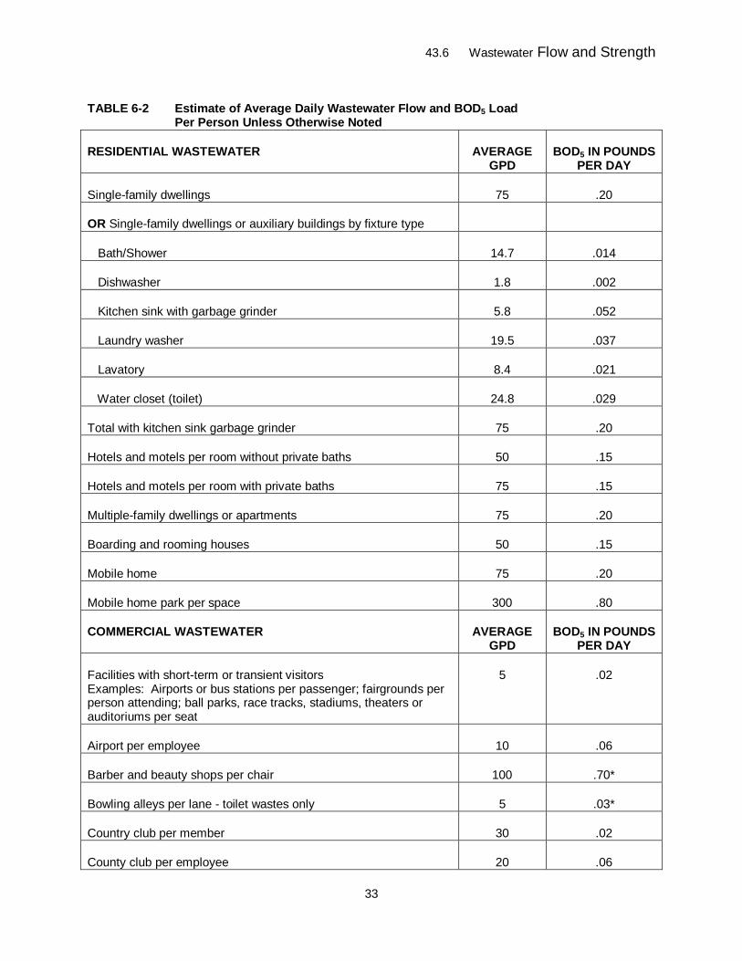
43.6 Wastewater Flow and Strength
33
TABLE 6-2 Estimate of Average Daily Wastewater Flow and BOD5 Load Per Person Unless Otherwise Noted
RESIDENTIAL WASTEWATER AVERAGE GPD
BOD5 IN POUNDS PER DAY
Single-family dwellings 75 .20
OR Single-family dwellings or auxiliary buildings by fixture type
Bath/Shower 14.7 .014
Dishwasher 1.8 .002
Kitchen sink with garbage grinder 5.8 .052
Laundry washer 19.5 .037
Lavatory 8.4 .021
Water closet (toilet) 24.8 .029
Total with kitchen sink garbage grinder 75 .20
Hotels and motels per room without private baths 50 .15
Hotels and motels per room with private baths 75 .15
Multiple-family dwellings or apartments 75 .20
Boarding and rooming houses 50 .15
Mobile home 75 .20
Mobile home park per space 300 .80
COMMERCIAL WASTEWATER AVERAGE GPD
BOD5 IN POUNDS PER DAY
Facilities with short-term or transient visitors Examples: Airports or bus stations per passenger; fairgrounds per person attending; ball parks, race tracks, stadiums, theaters or auditoriums per seat
5 .02
Airport per employee 10 .06
Barber and beauty shops per chair 100 .70*
Bowling alleys per lane - toilet wastes only 5 .03*
Country club per member 30 .02
County club per employee 20 .06
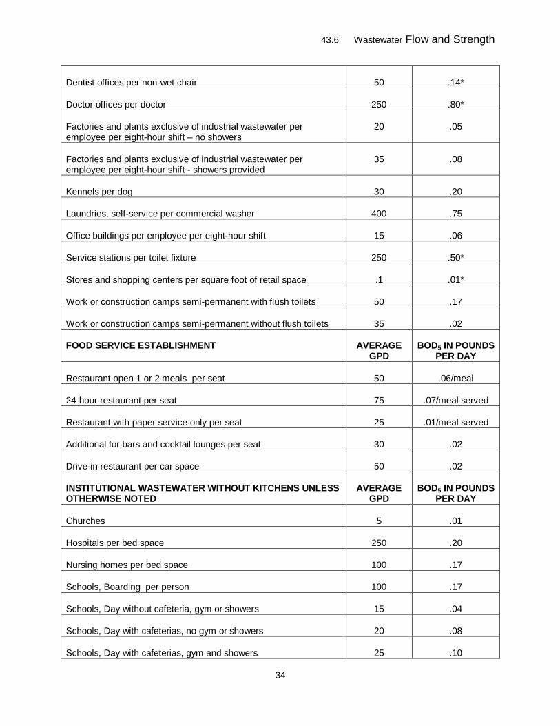
43.6 Wastewater Flow and Strength
34
Dentist offices per non-wet chair 50 .14*
Doctor offices per doctor 250 .80*
Factories and plants exclusive of industrial wastewater per employee per eight-hour shift – no showers
20 .05
Factories and plants exclusive of industrial wastewater per employee per eight-hour shift - showers provided
35 .08
Kennels per dog 30 .20
Laundries, self-service per commercial washer 400 .75
Office buildings per employee per eight-hour shift 15 .06
Service stations per toilet fixture 250 .50*
Stores and shopping centers per square foot of retail space .1 .01*
Work or construction camps semi-permanent with flush toilets 50 .17
Work or construction camps semi-permanent without flush toilets 35 .02
FOOD SERVICE ESTABLISHMENT AVERAGE GPD
BOD5 IN POUNDS PER DAY
Restaurant open 1 or 2 meals per seat 50 .06/meal
24-hour restaurant per seat 75 .07/meal served
Restaurant with paper service only per seat 25 .01/meal served
Additional for bars and cocktail lounges per seat 30 .02
Drive-in restaurant per car space 50 .02
INSTITUTIONAL WASTEWATER WITHOUT KITCHENS UNLESS OTHERWISE NOTED
AVERAGE GPD
BOD5 IN POUNDS PER DAY
Churches 5 .01
Hospitals per bed space 250 .20
Nursing homes per bed space 100 .17
Schools, Boarding per person 100 .17
Schools, Day without cafeteria, gym or showers 15 .04
Schools, Day with cafeterias, no gym or showers 20 .08
Schools, Day with cafeterias, gym and showers 25 .10
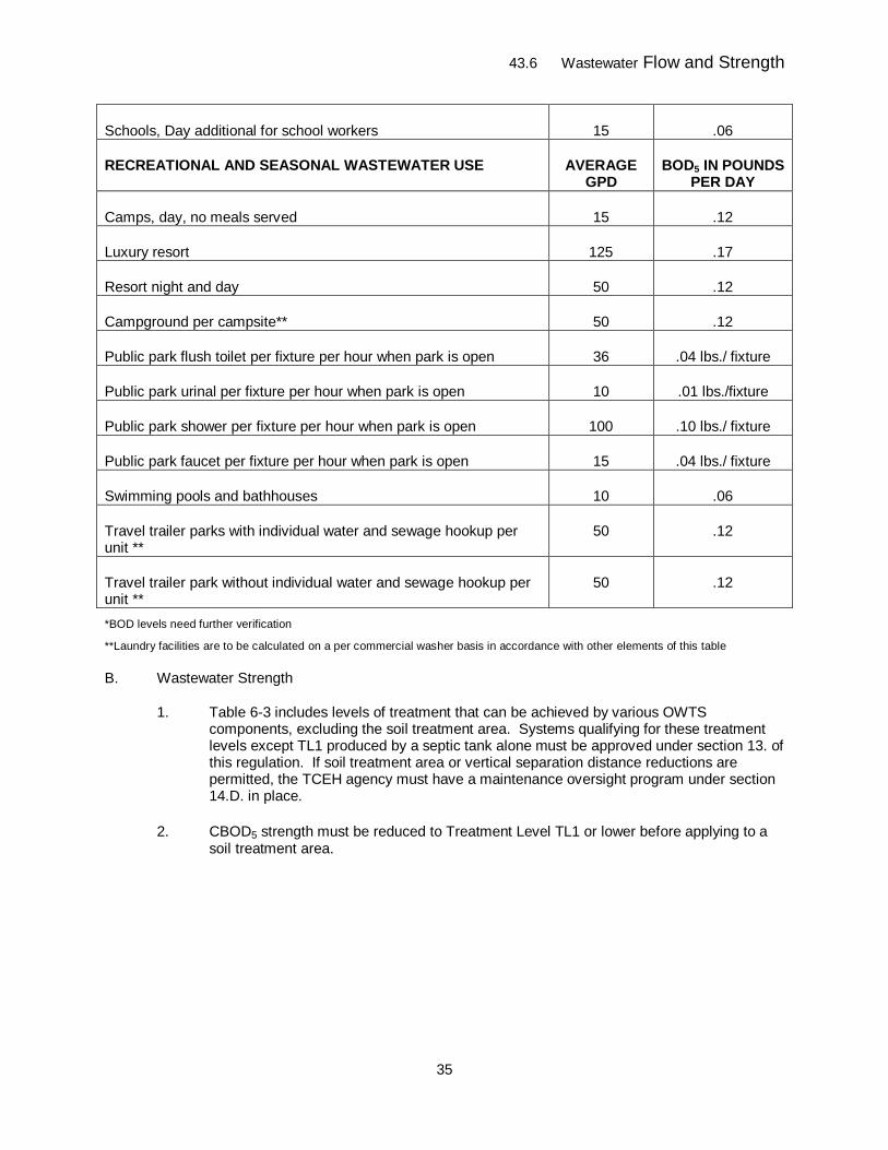
43.6 Wastewater Flow and Strength
35
Schools, Day additional for school workers 15 .06
RECREATIONAL AND SEASONAL WASTEWATER USE AVERAGE GPD
BOD5 IN POUNDS PER DAY
Camps, day, no meals served 15 .12
Luxury resort 125 .17
Resort night and day 50 .12
Campground per campsite** 50 .12
Public park flush toilet per fixture per hour when park is open 36 .04 lbs./ fixture
Public park urinal per fixture per hour when park is open 10 .01 lbs./fixture
Public park shower per fixture per hour when park is open 100 .10 lbs./ fixture
Public park faucet per fixture per hour when park is open 15 .04 lbs./ fixture
Swimming pools and bathhouses 10 .06
Travel trailer parks with individual water and sewage hookup per unit **
50 .12
Travel trailer park without individual water and sewage hookup per unit **
50 .12
*BOD levels need further verification
**Laundry facilities are to be calculated on a per commercial washer basis in accordance with other elements of this table
B. Wastewater Strength
1. Table 6-3 includes levels of treatment that can be achieved by various OWTS components, excluding the soil treatment area. Systems qualifying for these treatment levels except TL1 produced by a septic tank alone must be approved under section 13. of this regulation. If soil treatment area or vertical separation distance reductions are permitted, the TCEH agency must have a maintenance oversight program under section 14.D. in place.
2. CBOD5 strength must be reduced to Treatment Level TL1 or lower before applying to a soil treatment area.
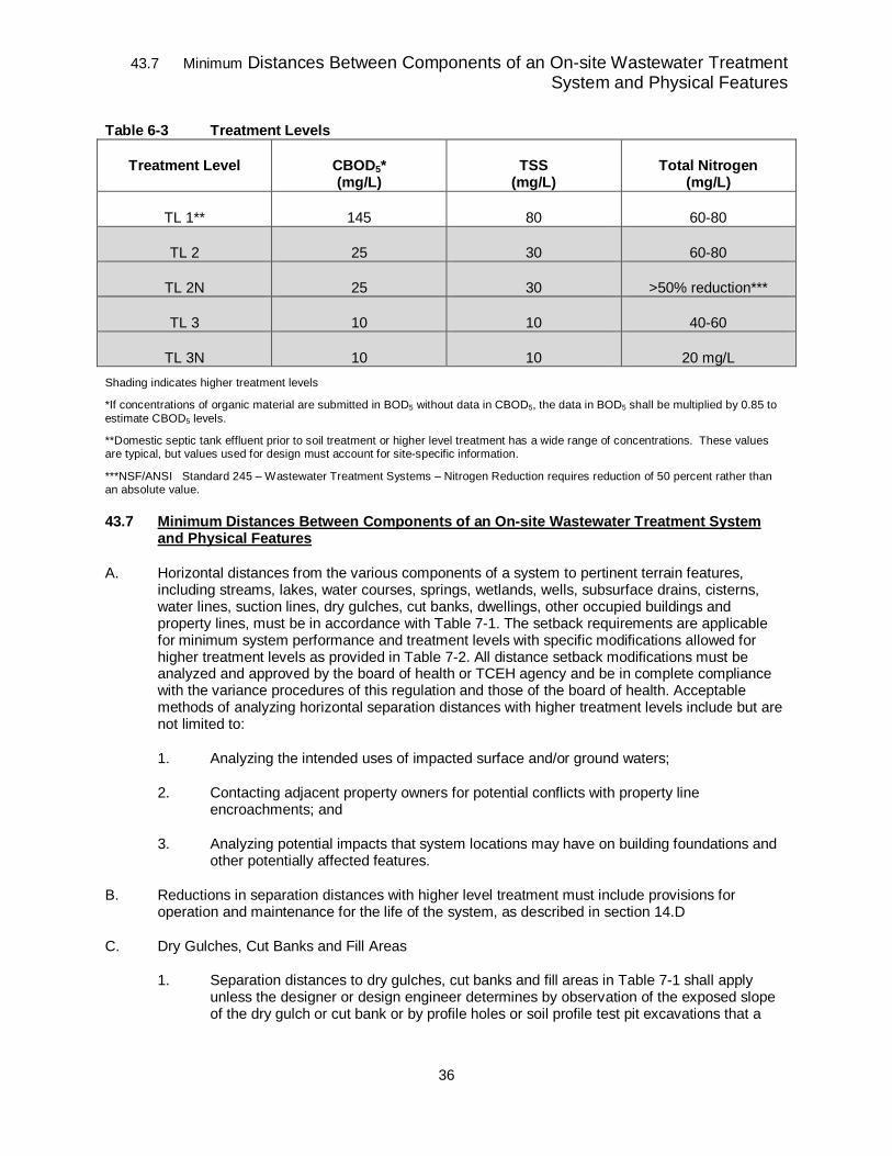
43.7 Minimum Distances Between Components of an On-site Wastewater Treatment System and Physical Features
36
Table 6-3 Treatment Levels
Treatment Level CBOD5* (mg/L)
TSS (mg/L)
Total Nitrogen (mg/L)
TL 1** 145 80 60-80
TL 2 25 30 60-80
TL 2N 25 30 >50% reduction***
TL 3 10 10 40-60
TL 3N 10 10 20 mg/L Shading indicates higher treatment levels
*If concentrations of organic material are submitted in BOD5 without data in CBOD5, the data in BOD5 shall be multiplied by 0.85 to estimate CBOD5 levels.
**Domestic septic tank effluent prior to soil treatment or higher level treatment has a wide range of concentrations. These values are typical, but values used for design must account for site-specific information.
***NSF/ANSI Standard 245 – Wastewater Treatment Systems – Nitrogen Reduction requires reduction of 50 percent rather than an absolute value.
43.7 Minimum Distances Between Components of an On-site Wastewater Treatment System and Physical Features
A. Horizontal distances from the various components of a system to pertinent terrain features, including streams, lakes, water courses, springs, wetlands, wells, subsurface drains, cisterns, water lines, suction lines, dry gulches, cut banks, dwellings, other occupied buildings and property lines, must be in accordance with Table 7-1. The setback requirements are applicable for minimum system performance and treatment levels with specific modifications allowed for higher treatment levels as provided in Table 7-2. All distance setback modifications must be analyzed and approved by the board of health or TCEH agency and be in complete compliance with the variance procedures of this regulation and those of the board of health. Acceptable methods of analyzing horizontal separation distances with higher treatment levels include but are not limited to:
1. Analyzing the intended uses of impacted surface and/or ground waters;
2. Contacting adjacent property owners for potential conflicts with property line encroachments; and
3. Analyzing potential impacts that system locations may have on building foundations and other potentially affected features.
B. Reductions in separation distances with higher level treatment must include provisions for operation and maintenance for the life of the system, as described in section 14.D
C. Dry Gulches, Cut Banks and Fill Areas
1. Separation distances to dry gulches, cut banks and fill areas in Table 7-1 shall apply unless the designer or design engineer determines by observation of the exposed slope of the dry gulch or cut bank or by profile holes or soil profile test pit excavations that a
43.7 Minimum Distances Between Components of an On-site Wastewater Treatment System and Physical Features
37
restrictive layer is present that will direct or allow the effluent from the soil treatment area to move laterally and surface.
2. A lesser distance may be used if it can be demonstrated by a professional engineer or professional geologist that the use of a barrier, such as a minimum 30 mil PVC liner placed between the soil treatment area and the slope of the dry gulch, cut bank or fill area will prevent effluent surfacing laterally.
3. The separation distance between a component and the crest of a dry gulch or cut bank will be evaluated for potential erosion or slope instability if the component and the slope are too close together. If there is potential for erosion or instability, the separation distance shall be increased until the risk is minimized.
D. Components of an OWTS listed in Table 7-1 shall be installed or located in accordance with the minimum distance requirements provided in the table or such increased distances provided by board of health regulations.
E. Table 7-2 provides the required site evaluation, design, and treatment level considerations necessary to evaluate the site and to design and locate the soil treatment area component of an OWTS.
1. Items 1, 2 and 3 in Table 7-2 address the allowable horizontal setback distance between the soil treatment area and the following physical features:
a. Setback distance from soil treatment area to on-site well;
b. Setback distance from soil treatment area to water features; and
c. Setback distance from soil treatment area to a dry gulch or cut bank.
2. Item 4 in Table 7-2 addresses the required vertical separation distance between the infiltrative surface of the soil treatment area and the restrictive layer or the required depth of soil comprising the soil treatment area.
3. The designer may select the level of treatment from Table 7-2 to be applied to the soil treatment area that is necessary in order to accommodate the site conditions, if higher level treatment for that purpose is permitted by the local public health agency.
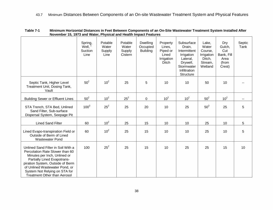
43.7 Minimum Distances Between Components of an On-site Wastewater Treatment System and Physical Features
38
Table 7-1 Minimum Horizontal Distances in Feet Between Components of an On-Site Wastewater Treatment System Installed After November 15, 1973 and Water, Physical and Health Impact Features
Spring, Well, 1
Suction Line
Potable Water Supply
Line
Potable Water Supply Cistern
Dwelling Occupied Building
Property Lines,
Piped or Lined
Irrigation Ditch
Subsurface Drain,
Intermittent Irrigation Lateral, Drywell,
Stormwater Infiltration Structure
Lake, Water
Course, Irrigation
Ditch, Stream, Wetland
Dry Gulch,
Cut Bank, Fill
Area (from Crest)
Septic Tank
Septic Tank, Higher Level Treatment Unit, Dosing Tank,
Vault
502 102 25 5 10 10 50 10 --
Building Sewer or Effluent Lines 502 102 252 0 102 102 502 102 --
STA Trench, STA Bed, Unlined Sand Filter, Sub-surface
Dispersal System, Seepage Pit
1003 252 25 20 10 25 503 25 5
Lined Sand Filter 60 102 25 15 10 10 25 10 5
Lined Evapo-transpiration Field or Outside of Berm of Lined
Wastewater Pond
60 102 25 15 10 10 25 10 5
Unlined Sand Filter in Soil With a Percolation Rate Slower than 60
Minutes per Inch, Unlined or Partially Lined Evapotrans-
piration System, Outside of Berm of Unlined Wastewater Pond, or System Not Relying on STA for Treatment Other than Aerosol
100 252 25 15 10 25 25 15 10
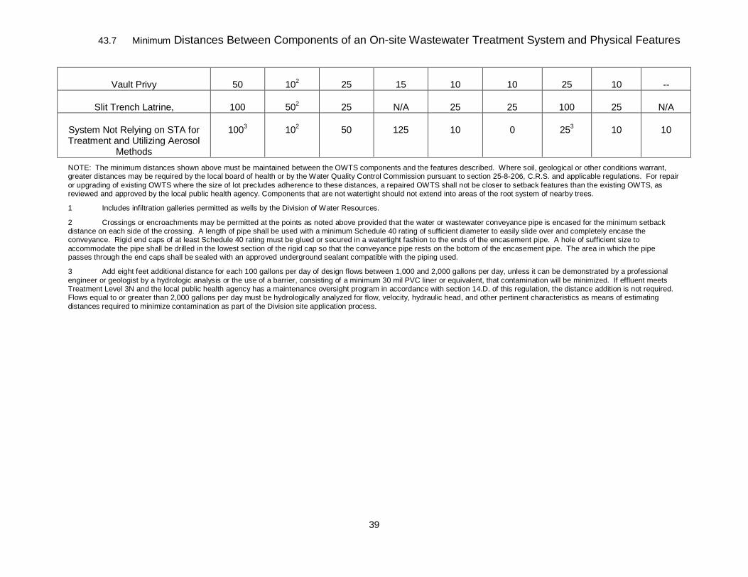
43.7 Minimum Distances Between Components of an On-site Wastewater Treatment System and Physical Features
39
Vault Privy 50 102 25 15 10 10 25 10 --
Slit Trench Latrine, 100 502 25 N/A 25 25 100 25 N/A
System Not Relying on STA for Treatment and Utilizing Aerosol
Methods
1003 102 50 125 10 0 253 10 10
NOTE: The minimum distances shown above must be maintained between the OWTS components and the features described. Where soil, geological or other conditions warrant, greater distances may be required by the local board of health or by the Water Quality Control Commission pursuant to section 25-8-206, C.R.S. and applicable regulations. For repair or upgrading of existing OWTS where the size of lot precludes adherence to these distances, a repaired OWTS shall not be closer to setback features than the existing OWTS, as reviewed and approved by the local public health agency. Components that are not watertight should not extend into areas of the root system of nearby trees.
1 Includes infiltration galleries permitted as wells by the Division of Water Resources.
2 Crossings or encroachments may be permitted at the points as noted above provided that the water or wastewater conveyance pipe is encased for the minimum setback distance on each side of the crossing. A length of pipe shall be used with a minimum Schedule 40 rating of sufficient diameter to easily slide over and completely encase the conveyance. Rigid end caps of at least Schedule 40 rating must be glued or secured in a watertight fashion to the ends of the encasement pipe. A hole of sufficient size to accommodate the pipe shall be drilled in the lowest section of the rigid cap so that the conveyance pipe rests on the bottom of the encasement pipe. The area in which the pipe passes through the end caps shall be sealed with an approved underground sealant compatible with the piping used.
3 Add eight feet additional distance for each 100 gallons per day of design flows between 1,000 and 2,000 gallons per day, unless it can be demonstrated by a professional engineer or geologist by a hydrologic analysis or the use of a barrier, consisting of a minimum 30 mil PVC liner or equivalent, that contamination will be minimized. If effluent meets Treatment Level 3N and the local public health agency has a maintenance oversight program in accordance with section 14.D. of this regulation, the distance addition is not required. Flows equal to or greater than 2,000 gallons per day must be hydrologically analyzed for flow, velocity, hydraulic head, and other pertinent characteristics as means of estimating distances required to minimize contamination as part of the Division site application process.
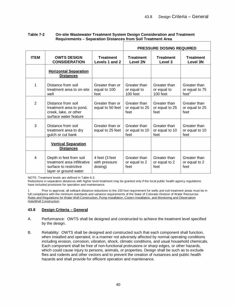
43.8 Design Criteria – General
40
Table 7-2 On-site Wastewater Treatment System Design Consideration and Treatment Requirements – Separation Distances from Soil Treatment Area
PRESSURE DOSING REQUIRED
ITEM OWTS DESIGN CONSIDERATION
Treatment Levels 1 and 2
Treatment Level 2N
Treatment Level 3
Treatment Level 3N
Horizontal Separation Distances
1 Distance from soil treatment area to on-site well
Greater than or equal to 100 feet
Greater than or equal to 100 feet
Greater than or equal to 100 feet
Greater than or equal to 75 feet1
2 Distance from soil treatment area to pond, creek, lake, or other surface water feature
Greater than or equal to 50 feet
Greater than or equal to 25 feet
Greater than or equal to 25 feet
Greater than or equal to 25 feet
3 Distance from soil treatment area to dry gulch or cut bank
Greater than or equal to 25 feet
Greater than or equal to 10 feet
Greater than or equal to 10 feet
Greater than or equal to 10 feet
Vertical Separation Distances
4 Depth in feet from soil treatment area infiltrative surface to restrictive layer or ground water
4 feet (3 feet with pressure dosing)
Greater than or equal to 2 feet
Greater than or equal to 2 feet
Greater than or equal to 2 feet
NOTE: Treatment levels are defined in Table 6-3. Reductions in separation distances with higher level treatment may be granted only if the local public health agency regulations have included provisions for operation and maintenance.
1 Prior to approval, all setback distance reductions to the 100 foot requirement for wells and soil treatment areas must be in full compliance with the minimum standards and variance requirements of the State of Colorado Division of Water Resources: Rules and Regulations for Water Well Construction, Pump Installation, Cistern Installation, and Monitoring and Observation Hole/Well Construction.
43.8 Design Criteria – General
A. Performance: OWTS shall be designed and constructed to achieve the treatment level specified by the design.
B. Reliability: OWTS shall be designed and constructed such that each component shall function, when installed and operated, in a manner not adversely affected by normal operating conditions including erosion, corrosion, vibration, shock, climatic conditions, and usual household chemicals. Each component shall be free of non-functional protrusions or sharp edges, or other hazards, which could cause injury to persons, animals, or properties. Design shall be such as to exclude flies and rodents and other vectors and to prevent the creation of nuisances and public health hazards and shall provide for efficient operation and maintenance.
43.8 Design Criteria – General
41
C. Accessibility for Inspection, Maintenance, and Servicing
1. Septic tanks shall have risers over each access manhole and all risers shall extend to or above final grade. The maximum soil cover over the top of a septic tank is 48” unless otherwise approved by TCEH.
2. Each treatment component of an OWTS other than the septic tank and soil treatment area shall be equipped with access manholes with risers that extend to or above final grade, located to permit periodic physical inspection, collection and testing of samples and maintenance of all components and compartments.
3. Riser Lids
a. Each riser lid brought to the surface shall have a secure closing mechanism, such as a lock, special headed bolts or screws, or sufficient weight to prevent unauthorized access.
b. The Board of Health may, by further adopted regulations, require a secondary plug, cap, cover or screen be provided below the riser cover to prevent tank entry if the cover is unknowingly damaged or removed.
4. Components that require access for maintenance shall include but not be limited to submerged bearings, moving parts, pumps, siphons, valves, tubes, intakes, slots, distribution boxes, drop boxes, cleanouts, effluent screens, filters, inlet and outlet baffles, aerators, treatment equipment and other devices.
5. Components shall be designed and constructed so that, when installed, they shall be easily maintained, sampled, and serviced according to the manufacturer’s recommendations. Easy physical access to treatment components by maintenance personnel and equipment shall be provided.
D. Plumbing Codes: Plumbing fixtures, building sewers, vents, sewer lines and other appurtenances shall be designed, operated and maintained so as to comply with the minimum requirements of the most recently revised locally enforceable plumbing code. In absence of a local plumbing code, designs shall adhere to the Colorado Plumbing Code (3 CCR 720-1). A local plumbing permit may be required.
E. Electrical Equipment, If Used
1. All electrical work, equipment, and material shall comply with the requirements of the currently applicable National Electrical Code as designated by the State Electrical Board Rules and Regulations (3 CCR 710-1). A local electrical permit shall be required.
2. Electrical components shall be protected from moisture and corrosive gases.
F. Indicators of Failure or Malfunctioning for Systems Utilizing Mechanical Apparatus: A signal device shall be installed which will provide a recognizable indication or warning to the user that the system or component is not operating or is operating but malfunctioning. This indication or warning shall be a visual signal or an audible signal or both and shall be located in a centralized area within visual and audible range of the system user. A signal or message may also be sent remotely to a maintenance provider.
43.8 Design Criteria – General
42
G. Sampling Access
1. If sampling for testing or as a requirement for a permit will be required of effluent from a component other than the soil treatment area, an accessible sampling point shall be provided.
2. If sampling of the treated wastewater from the soil treatment area will be required for testing or as a requirement for a permit, a monitoring well or wells shall be constructed. Monitoring wells shall be located down gradient from the soil treatment area, accessible, and provided with a properly securable cover at or above the ground surface. Monitoring wells up gradient of the system may also be required. Lysimeters or other collection devices under the soil treatment area may be used instead of a monitoring well if approved by the TCEH agency or other issuer of a permit.
H. Component Operating Instructions
1. The manufacturer of proprietary treatment units utilizing mechanical components shall provide clear, concise written instructions covering the components which, when followed, shall assure proper installation and safe and satisfactory operation and maintenance.
2. If the OWTS uses public domain technology, the design engineer shall provide clear, concise written instructions covering the components which, when followed, shall assure proper installation and safe and satisfactory operation and maintenance.
I. Surface Activity: Activity or use on the surface of the ground over any part of the OWTS must be restricted to that which shall allow the system to function as designed and which shall not contribute to compaction of the soil or to structural loading detrimental to the structural integrity or capability of the component to function as designed. During construction, equipment shall be kept off of the ground surface above the soil treatment area and out of the excavation to prevent compaction. If compaction occurs, the disturbed or compacted soil shall be re-evaluated and new percolation tests may be performed to the disturbed or compacted soil and the system redesigned if the parameters have changed.
J. Floodplains
1. New OWTS and replacement OWTS installed in a 100-year floodplain shall meet or exceed the requirements of the Federal Emergency Management Agency and the Teller County Community Development Services Department. Repairs of an existing system shall meet the requirements as feasible. The system as approved by TCEH agency shall be designed to minimize or eliminate infiltration of floodwaters into the system and discharge from the system into the floodwaters.
2. No new or expanded OWTS shall be installed in a floodway designated in a 100-year floodplain. For any system repair that may affect the floodway delineation, appropriate procedures shall be followed including revision of the floodway designation, if necessary.
K. Business Commercial, Industrial, Institutional or Multi-Family Dwelling Wastewater Systems
1. An OWTS that will serve a business, commercial, industrial or institutional property, or a multifamily dwelling shall:
a. Be designed by a professional engineer;
43.9 Design Criteria - Components
43
b. Receive only such biodegradable wastes for treatment and distribution as are compatible with those biological treatment processes as occur within the septic tank, any additional treatment unit and the soil treatment area; and
c. Receive authorization by rule or a class V underground injection permit from the United States Environmental Protection Agency (EPA) before an application for an OWTS permit is approved if the system may receive non-residential wastewater or is otherwise covered by the EPA underground injection control program.
43.9 Design Criteria - Components
A. Tanks and Vaults
1. Watertightness
a. Septic tanks, vaults, pump tanks, other treatment components, risers and lids shall not allow infiltration of ground water or surface water and shall not allow the release of wastewater or liquids through other than designed openings.
b. Acceptable watertightness testing methods performed at a manufacturer’s site or in the field include water filling the tank or vacuum testing.
2. Tank Anchoring: In locations where ground water or floodwaters may cause instability problems to the septic tank, vault, or other treatment unit in the OWTS due to flotation, the tank, vault or unit shall be anchored in a manner sufficient to provide stability when the tank is empty. Risers shall be included in the buoyancy calculations.
a. If a manufacturer provides recommendations for anchoring designs, they may be used if they meet the conditions present at the site.
b. If a manufacturer does not provide recommendations for provisions to compensate for buoyancy, or if the professional engineer chooses to provide his/her own designs, the anchoring system design shall be prepared by the professional engineer.
3. Identification and Data Marking: All tanks and treatment units shall be permanently and legibly marked in a location for the purpose of inspection that is readily visible when inspected before backfilling. The marking inscription shall include the following:
a. Name of manufacturer;
b. Model or serial number, if available;
c. Effective volume and unit of measure;
d. Maximum depth of earth cover and external loads the tanks is designed to resist; and
e. Inlet and outlet identifications, if relevant.
B. Septic Tanks
1. The manufacturer shall provide sufficient information to demonstrate that the tank will meet the design specification.
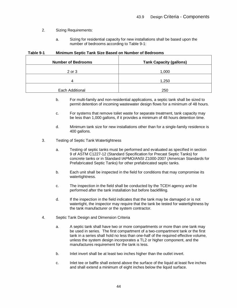
43.9 Design Criteria - Components
44
2. Sizing Requirements:
a. Sizing for residential capacity for new installations shall be based upon the number of bedrooms according to Table 9-1:
Table 9-1 Minimum Septic Tank Size Based on Number of Bedrooms
Number of Bedrooms Tank Capacity (gallons)
2 or 3 1,000
4 1,250
Each Additional 250
b. For multi-family and non-residential applications, a septic tank shall be sized to permit detention of incoming wastewater design flows for a minimum of 48 hours.
c. For systems that remove toilet waste for separate treatment, tank capacity may be less than 1,000 gallons, if it provides a minimum of 48 hours detention time.
d. Minimum tank size for new installations other than for a single-family residence is 400 gallons.
3. Testing of Septic Tank Watertightness
a. Testing of septic tanks must be performed and evaluated as specified in section 9 of ASTM C1227-12 (Standard Specification for Precast Septic Tanks) for concrete tanks or in Standard IAPMO/ANSI Z1000-2007 (American Standards for Prefabricated Septic Tanks) for other prefabricated septic tanks.
b. Each unit shall be inspected in the field for conditions that may compromise its watertightness.
c. The inspection in the field shall be conducted by the TCEH agency and be performed after the tank installation but before backfilling.
d. If the inspection in the field indicates that the tank may be damaged or is not watertight, the inspector may require that the tank be tested for watertightness by the tank manufacturer or the system contractor.
4. Septic Tank Design and Dimension Criteria
a. A septic tank shall have two or more compartments or more than one tank may be used in series. The first compartment of a two-compartment tank or the first tank in a series shall hold no less than one-half of the required effective volume, unless the system design incorporates a TL2 or higher component, and the manufactures requirement for the tank is less.
b. Inlet invert shall be at least two inches higher than the outlet invert.
c. Inlet tee or baffle shall extend above the surface of the liquid at least five inches and shall extend a minimum of eight inches below the liquid surface.
43.9 Design Criteria - Components
45
d. Outlet tee or baffle shall extend at least 14 inches below the outlet invert and, if needed, be modified to accommodate an effluent screen. The outlet tee or baffle that accommodates an effluent screen must be located so that the effluent screen has sufficient clearance to be removed through the access opening with a riser in place.
e. The distance from the outlet invert to the underside of the tank top shall be at least ten inches.
f. Liquid depth shall be a minimum of 30 inches and the maximum depth shall not exceed the tank length.
g. The transfer of liquid from the first compartment to the second or successive compartment shall be made at a liquid depth of between 35 and 40 percent of the liquid depth measured from the liquid surface.
h. At least one access manhole no less than 20 inches across shall be provided in each compartment of a septic tank.
i. A septic tank shall have a minimum of 25 square feet of liquid surface area and have at least a six-foot separation between inlets and outlets. Septic tanks in series, combined, shall have a minimum of 25 square feet of liquid surface area and the sum of the distances between inlets and outlets of all tanks must be at least six feet. The requirements for liquid surface area and separation between inlet and outlet may be waived for tanks with less than 750 gallon effective volume.
5. Concrete Septic Tank Structural Design
a. Concrete septic tanks shall comply with the structural design criteria of ASTM C1227-12 (Standard Specification for Precast Septic Tanks).
b. The design for each tank model and size by each manufacturer must be certified by a professional engineer as complying with these design and structural requirements and the watertightness standard of this regulation.
c. Certification by a professional engineer must be submitted to the Division for acceptance.
d. Tank slab lids or mid-seam tanks shall be sealed to be watertight.
e. Connections between tank and risers shall be sealed to be watertight.
6. Fiberglass, Fiberglass-Reinforced Polyester, and Plastic Tanks
a. All fiberglass, fiberglass-reinforced polyester, and plastic tanks shall meet the minimum design and structural criteria of IAPMO/ANSI Z1000-2007 (American Standards for Prefabricated Septic Tanks) and be certified by a professional engineer as meeting these standards. The professional engineer certifying the criteria must be registered or licensed in the United States, but need not be registered in Colorado.
b. All tanks shall be sold and delivered by the manufacturer or manufacturer’s designated representative, preferably completely assembled. On-site tank assembly will be allowed on an as-needed basis.
43.9 Design Criteria - Components
46
c. Tanks shall be structurally sound and support external forces as specified in the standard referenced above when empty and internal forces when full. Tanks shall not deform or creep resulting in deflection of more than five percent in shape as a result of loads imposed.
d. All tanks shall be constructed of sound, durable materials and not be subject to excessive corrosion, decay, frost damage, or cracking.
e. All seams or connections including to risers shall be sealed to be watertight.
7. Metal tanks are prohibited.
C. Abandonment of Tank
1. A tank may be completely removed and the parts disposed of safely.
2. If the tank will remain in place:
a. The tank shall be pumped to remove as much waste as possible;
b. The bottom of the tank shall be broken so the tank neither floats nor fills with water;
c. The top must be collapsed and the sides may be broken into the void;
d. The remaining void shall be filled with gravel, sand or compacted soil; and
e. The filled excavation will be graded to surroundings, allowing for settling.
3. The TCEH agency may require abandonment of a tank that is deemed to be a hazard.
D. Effluent Lines, Pipe Standards and Bedding Requirements:
1. Effluent Lines
a. The first 5 feet of the effluent line entering, and leaving the septic tank or advanced treatment system shall be 4 inch Schedule 40 PVC.
b. A cleanout installed with a sanitary tee or wye shall be installed at least every 100 feet in a run of effluent pipe from the dwelling or structure to the tank or advanced treatment system, and from the septic tank or advanced treatment system to the soil treatment area.
2. Pipe Standards
a. All wastewater lines used in an OWTS shall be constructed of compatible pipe, primer, bonding agent, and fittings.
b. Where unperforated plastic pipe and fittings are used for gravity flow, the minimum wall thickness of the pipe shall conform to ASTM Standard D 3034 or equivalent or greater strength. Schedule 40 pipe is preferred.
c. Perforated distribution pipe surrounded by rock within a soil treatment area shall have a minimum wall thickness and perforations conforming to ASTM Standard D 2729 or equivalent or greater strength. Corrugated polyethylene pipe with
43.9 Design Criteria - Components
47
smooth interior that meets ASTM F405 or AASHTO M252 specifications or equivalent may be used.
d. Schedule 40 or pipe of equivalent or greater strength shall be used for the placement of piping under driveways or roadways and in instances where sewer line setback distances are granted a variance for any reason.
e. Tile pipe, open-joint pipe, and cast iron pipe must not be used in an OWTS.
f. Pressure pipe must be rated for the intended use to accommodate pump discharge pressure.
3. Bedding: All system piping, except for distribution laterals within the soil treatment area, shall be bedded with select material before final inspection by the TCEH agency. Select bedding material shall consist of loose, granular material, free from stones, clods, frozen soil, or other deleterious material. Select material may consist of on-site job-excavated or imported material. Bedding material must be mechanically compacted to support piping.
E. Distribution Box: A distribution box, if used, shall be of sufficient size to distribute effluent equally to the lateral lines of a trench or absorption bed system. The box shall be constructed with the inlet invert at least one inch above the level of the outlet inverts. Flow equalizers or similar devices shall be used to adjust the flow between lines. Access to the box shall be provided with a manhole riser with access lid at or above grade if the top of the box does not reach final grade.
F. Drop Box: In sequential or serial distribution, a watertight box may be used to transfer the effluent to the following trench when the effluent in a trench has received the designed level for overflow to the next trench. A drop box shall have a riser at or above final grade, if the top of the drop box does not reach final grade. Outlet lines in sequential distribution shall be designed and installed so that they may be capped off for resting periods.
G. Stepdown/Relief Line: In sequential or serial distribution, an unperforated pipe may be used to transfer the effluent to the following trench when the effluent in a trench has received the designed level for overflow from that trench.
H. Wastewater Pumping and Dosing Siphon Systems
1. Pumps
a. Non-clog pump opening shall have at least two-inch diameter solids handling capacity where raw wastewater is pumped. A pump opening shall not have more than 3/4-inch diameter solids handling capacity if previously settled effluent is pumped.
b. Pumps must be certified to the applicable UL or CSA electrical safety standard, bear the seal of approval of CSA, UL or an equivalent testing program and be constructed of corrosion resistant materials.
c. Grinder pumps must also be certified to NSF/ANSI Standard 46 and bear the seal of approval of the NSF or equivalent testing and certification program.
2. Floats and Switches
a. Automatic liquid level controls must be provided to start and shut off pumps at a frequency or level specified in the design.
43.9 Design Criteria - Components
48
b. Floats must be mounted on a stem separate from the pump discharge piping to allow for removal, adjustment, and replacement of the float without removing the pump.
c. Float switches must be certified to the applicable UL or CSA electrical safety standard, bear the seal of approval of CSA, UL or an equivalent certification program and be constructed of corrosion resistant materials.
3. Location of Pump or Siphon
a. A pump may be, or a siphon shall be, installed in a separate tank following the septic tank and be of sufficient volume to allow pump or siphon cycling commensurate with the design capacity. The use of a three-compartment septic tank, sized to provide effective volume in the first two compartments with the pump in the third compartment, is acceptable.
b. The second compartment of the septic tank shall not be used as the pump tank unless it can be demonstrated to the satisfaction of the local public health agency that the minimum 48-hour detention time will not be decreased and the pump is screened or provided with an approved filtering device to assure that only liquid effluent will be discharged.
4. Pump or Siphon Discharge Piping
a. The discharge line from the pumping or siphon chamber shall be protected from freezing by burying the pipe below frost level or sloping the pipe to allow it to be self-draining. Drainage shall be provided through the bottom of the pump or through a weep hole located in the discharge line prior to exiting the tank.
b. The pump discharge piping shall have a quick disconnect union that is easily accessible from grade within the riser to allow for easy pump access and removal.
c. The pipe shall be sized to maintain a velocity of two or more feet per second.
d. Automatic air/vacuum release valves shall be installed at high points in the pressure line where necessary to prevent air or vacuum locking and allow self draining of the lines.
5. Access
a. The pump or dosing system tank, chamber, or compartment shall have a minimum 24-inch diameter access riser, made of corrosion-resistant material, extending to or above ground level.
b. The access riser must have a watertight connection to the pump or dosing chamber/compartment to prevent infiltration or exfiltration.
6. Splice Box
a. Splice boxes shall be located outside the pump system access riser and be accessible from the ground surface.
b. No wire splices shall be made inside the tank, dosing chamber or riser. Wire splicing shall be completed with corrosion-resistant, watertight connectors.
43.10 Design Criteria– Soil Treatment Area
49
7. Controls
a. The pump system shall have an audible and visual alarm notification in the event an excessively high water condition occurs.
b. The pump shall be connected to a control breaker separate from the high water alarm breaker and from any other control system circuits.
c. The pump system shall have a switch so the pump can be manually operated.
d. The pump system for pressure dosing and higher level treatment systems shall have a mechanism for tracking either the amount of time the pump runs or the number of cycles the pump operates.
e. Control panels shall be UL listed.
I. Effluent Screens
1. Effluent screens are required to be installed in all septic tanks in new installations and repairs where the septic tank is replaced.
2. If a pump or dosing siphon is used to remove septic tank effluent from the final compartment of the septic tank, an effluent screen must be provided prior to the pump or siphon inlet. A pump vault equipped with a filter cartridge may be considered equivalent to an effluent screen preceding the pump.
3. The effluent screen shall be cleaned at manufacturer-recommended intervals, or more often, if use patterns indicate.
4. An alarm may be installed on an effluent screen indicating need for maintenance. The Board of Health may, by further adopted regulation, require all effluent screens to be equipped with alarms.
J. Grease Interceptor Tanks
1. All commercial food service facilities and other facilities generating fats, oils and greases in their waste must install a grease interceptor tank.
2. Grease interceptor tanks shall treat only those portions of the total wastewater flow in which grease and oils are generated.
43.10 Design Criteria– Soil Treatment Area
A. The size and design of the soil treatment area shall be based on the results of the site and soil evaluation, design criteria, and construction standards for the proposed site and OWTS selected.
B. At proposed soil treatment area locations where any of the following conditions are present, the system shall be designed by a professional engineer and approved by the TCEH agency:
1. The soil classifications are Types 0, 3A, 4, 4A, and 5 and 5 and Treatment Levels TL2, TL2N, TL3, and TL3N as specified in Table 10-1 of this regulation;
2. The maximum seasonal level of the ground water surface is less than four feet below the bottom of the proposed absorption system;
43.10 Design Criteria– Soil Treatment Area
50
3. A restrictive layer exists less than four feet below the bottom of the proposed absorption system;
4. The ground slope is in excess of thirty percent; or
5. Pressure distribution is used.
C. Calculation of Infiltrative Surface of Soil Treatment Area
1. The infiltrative surface of a trench or bed receiving any treatment level of effluent is only the bottom area. No sidewall credit is allowed except in deep gravel trenches and seepage pits that are permissible in repairs.
2. Long-term acceptance rates (LTARs) are shown in Table 10-1.
3. Factors for adjusting the size of the soil treatment area are in Tables 10-2 and 10-3.
4. The required area for a soil treatment area is determined by the following formula:
Soil Treatment Area in square feet required = Design Flow (in gallons per day) LTAR (in gallons per day per square foot)
a. Adjusted Soil Treatment Area = Required Soil Treatment Area x Size Adjustment Factor(s).
b. Size adjustment factors for methods of application are in Table 10-2.
c. Size adjustment factors for types of storage/distribution media are in Table 10-3.
d. A required soil treatment area receiving TL1 effluent may be multiplied by one size adjustment factor from Table 10-2, Table 10-3, or both.
e. A soil treatment area receiving TL2, TL2N, TL3, or TL3N effluent must be pressure dosed. The distribution media in Table 10-3 may be used for distribution of higher level treatment system effluent, but an additional reduction factor from Table 10-3 shall not be used.
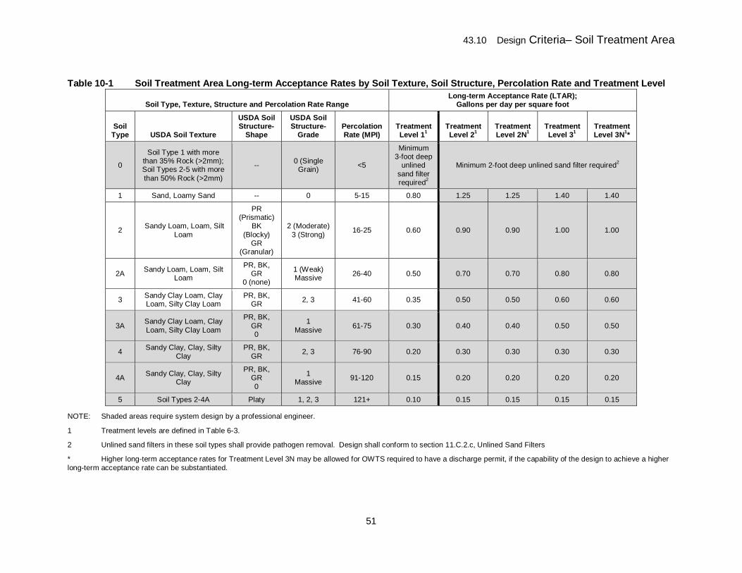
43.10 Design Criteria– Soil Treatment Area
51
Table 10-1 Soil Treatment Area Long-term Acceptance Rates by Soil Texture, Soil Structure, Percolation Rate and Treatment Level
Soil Type, Texture, Structure and Percolation Rate Range Long-term Acceptance Rate (LTAR);
Gallons per day per square foot
Soil Type USDA Soil Texture
USDA Soil Structure-
Shape
USDA Soil Structure-
Grade Percolation Rate (MPI)
Treatment Level 11
Treatment Level 21
Treatment Level 2N1
Treatment Level 31
Treatment Level 3N1*
0
Soil Type 1 with more than 35% Rock (>2mm); Soil Types 2-5 with more than 50% Rock (>2mm)
-- 0 (Single Grain) <5
Minimum 3-foot deep
unlined sand filter required2
Minimum 2-foot deep unlined sand filter required2
1 Sand, Loamy Sand -- 0 5-15 0.80 1.25 1.25 1.40 1.40
2 Sandy Loam, Loam, Silt Loam
PR (Prismatic)
BK (Blocky)
GR (Granular)
2 (Moderate) 3 (Strong) 16-25 0.60 0.90 0.90 1.00 1.00
2A Sandy Loam, Loam, Silt Loam
PR, BK, GR
0 (none)
1 (Weak) Massive 26-40 0.50 0.70 0.70 0.80 0.80
3 Sandy Clay Loam, Clay Loam, Silty Clay Loam
PR, BK, GR 2, 3 41-60 0.35 0.50 0.50 0.60 0.60
3A Sandy Clay Loam, Clay Loam, Silty Clay Loam
PR, BK, GR 0
1 Massive 61-75 0.30 0.40 0.40 0.50 0.50
4 Sandy Clay, Clay, Silty Clay
PR, BK, GR 2, 3 76-90 0.20 0.30 0.30 0.30 0.30
4A Sandy Clay, Clay, Silty Clay
PR, BK, GR 0
1 Massive 91-120 0.15 0.20 0.20 0.20 0.20
5 Soil Types 2-4A Platy 1, 2, 3 121+ 0.10 0.15 0.15 0.15 0.15
NOTE: Shaded areas require system design by a professional engineer.
1 Treatment levels are defined in Table 6-3.
2 Unlined sand filters in these soil types shall provide pathogen removal. Design shall conform to section 11.C.2.c, Unlined Sand Filters
* Higher long-term acceptance rates for Treatment Level 3N may be allowed for OWTS required to have a discharge permit, if the capability of the design to achieve a higher long-term acceptance rate can be substantiated.
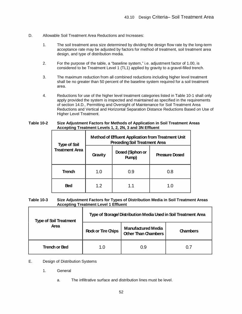
43.10 Design Criteria– Soil Treatment Area
52
D. Allowable Soil Treatment Area Reductions and Increases:
1. The soil treatment area size determined by dividing the design flow rate by the long-term acceptance rate may be adjusted by factors for method of treatment, soil treatment area design, and type of distribution media.
2. For the purpose of the table, a “baseline system,” i.e. adjustment factor of 1.00, is considered to be Treatment Level 1 (TL1) applied by gravity to a gravel-filled trench.
3. The maximum reduction from all combined reductions including higher level treatment shall be no greater than 50 percent of the baseline system required for a soil treatment area.
4. Reductions for use of the higher level treatment categories listed in Table 10-1 shall only apply provided the system is inspected and maintained as specified in the requirements of section 14.D., Permitting and Oversight of Maintenance for Soil Treatment Area Reductions and Vertical and Horizontal Separation Distance Reductions Based on Use of Higher Level Treatment.
Table 10-2 Size Adjustment Factors for Methods of Application in Soil Treatment Areas Accepting Treatment Levels 1, 2, 2N, 3 and 3N Effluent
Type of Soil Treatment Area
Method of Effluent Application from Treatment Unit Preceding Soil Treatment Area
Gravity Dosed (Siphon or Pump) Pressure Dosed
Trench 1.0 0.9 0.8
Bed 1.2 1.1 1.0
Table 10-3 Size Adjustment Factors for Types of Distribution Media in Soil Treatment Areas Accepting Treatment Level 1 Effluent
Type of Soil Treatment Area
Type of Storage/Distribution Media Used in Soil Treatment Area
Rock or Tire Chips Manufactured Media Other Than Chambers Chambers
Trench or Bed 1.0 0.9 0.7
E. Design of Distribution Systems
1. General
a. The infiltrative surface and distribution lines must be level.
43.10 Design Criteria– Soil Treatment Area
53
b. The infiltrative surface must be no deeper than four feet unless adequate treatment at a deeper level can be demonstrated and is approved by the local public health agency. The depth will be measured on the downslope side of the trench or bed.
c. Trenches must follow the ground surface contours so variations in infiltrative surface depth are minimized. Beds must be oriented along contours to the degree possible.
d. Pipe for gravity distribution must be no less than three inches in diameter.
e. A final cover of soil suitable for vegetation at least ten inches deep must be placed from the top of the geotextile or similar pervious material in a rock and pipe system, chamber, or manufactured media up to the final surface grade of the soil treatment area.
f. Following construction, the ground surface must be graded to divert stormwater runoff or other outside water from the soil treatment area. The area must be protected against erosion. Subsurface drains upslope of the soil treatment area may be installed to divert subsurface flow around the area.
g. Backfilling and compaction of soil treatment areas shall be accomplished in a manner that does not impair the intended function and performance of the storage/distribution media and soil and distribution laterals, allows for the establishment of vegetative cover, minimizes settlement and maintains proper drainage.
2. Distribution Lines
a. Distribution between lines in a soil treatment area must be as even as possible. Uneven settling of portions of the distribution system following construction must be addressed by provisions in the design to adjust flows between lines.
b. Distribution lines shall be a maximum of 100 feet long.
c. The end of a distribution pipe must be capped, unless it is in a bed or trenches in a level soil treatment area, where the ends of the lines may be looped.
d. Inspection Ports
(1) An inspection port accessible from ground surface must be installed at the terminal end of each line. The bottom of the inspection port tube must extend to the infiltrative surface and not be connected to the end of the distribution pipe. Inspection ports in chambers may be installed according to manufacturer’s instructions if the infiltrative surface is visible or can be measured from the inspection port.
(2) Additional inspection ports connected to distribution pipes may be installed.
(3) In addition, TCEH agency shall require an inspection port at the initial end of each line.
43.10 Design Criteria– Soil Treatment Area
54
(4) The top of inspection ports may be below the final grade of the surface if each has a cover at the surface such as a valve box for a lawn irrigation system.
e. Trenches
(1) Trenches must be three feet wide or less.
(2) The separating distance between trenches must be a minimum of six feet sidewall-to-sidewall.
(3) Perforated distribution pipe used in a trench must be as close to the center of the trench as possible.
(4) Perforations must be oriented downward unless pressure distribution is used and provision for pipe drainage is included.
f. Beds
(1) Maximum width for a bed must be 12 feet, unless the bed receives effluent meeting Treatment Level 2 quality or better.
(2) The separating distance between beds must be a minimum of six feet sidewall-to-sidewall.
(3) The separating distance between parallel distribution lines in an absorption bed must not exceed six feet and a distribution line must be located within three feet of each sidewall and endwall of the absorption bed.
g. Serial and Sequential Distribution:
(1) A serial or sequential distribution system may be used where the ground slope does not allow for suitable installation of a single level soil treatment area unless a distribution box or dosing chamber is used.
(2) The horizontal distance from the side of the absorption system to the surface of the ground on a slope must be adequate to prevent lateral flow and surfacing.
(3) Adjacent trenches or beds must be connected with a stepdown/relief line or a drop box arrangement such that each trench fills with effluent to the top of the gravel or chamber outlet before flowing to succeeding treatment areas.
3. Storage/Distribution Media
a. Rock and Pipe
(1) The pipe must be surrounded by clean, graded gravel, rock, or other material of equal efficiency which may range in size from 1/2 inch to 2 1/2 inches. At least six inches of gravel, rock or other material must be placed below the pipe. The gravel, rock or other material must fill the trench around the pipe and at least two inches above the top of the distribution pipe.
43.10 Design Criteria– Soil Treatment Area
55
(2) The top of the placed gravel or such material used must be covered with non-woven permeable geotextile meeting a maximum thickness rating of 2.0 ounces per square yard or equivalent pervious material. An impervious covering must not be used.
b. Tire Chips
(1) The pipe may be surrounded with clean, uniformly-sized tire chips.
(2) Tire chips must be nominally two inches in size and may range from 1/2 inch to a maximum of four inches in any one direction.
(3) Wire strands must not protrude from the tire chips more than 0.75 inches.
(4) Tire chips must be free from balls of wire and fine particles less than two mm across.
(5) The top of the tire chips used must be covered with non-woven permeable geotextile meeting a maximum thickness rating of 2.0 ounces per square yard or equivalent pervious material. An impervious covering must not be used.
c. Chambers
(1) Chambers must be installed with the base on the infiltrative surface.
(2) Installation must be according to manufacturer’s instructions.
(3) Effluent may be distributed by gravity or pressure dosing.
d. Manufactured Media
(1) Manufactured media must be installed with the base on the infiltrative surface.
(2) Installation must be according to manufacturer’s instructions.
(3) Effluent may be applied by pressure distribution only if the manufacturer specifies suitability of the product for that use.
e. Pressure Distribution
(1) Design of pressure distribution systems must include:
(i) Dose size and frequency for flows and soil or media long-term acceptance rate;
(ii) Pipe diameter and strength requirements;
(iii) Orifice size and spacing; and
(iv) Distal pressure head.
43.10 Design Criteria– Soil Treatment Area
56
(2) Cleanouts must be installed at the end of each line, and easily accessible for maintenance.
f. Driplines
(1) The infiltrative surface area must be calculated using the long-term acceptance rate for the site or a more conservative value if recommended by the manufacturer.
(2) Driplines must be installed on manufacturer’s spacing recommendations.
(3) Drainback must be provided for all drip lines, pipes and pumps.
(4) Provisions must be made to minimize freezing in the distribution lines, driplines, relief valves, and control systems.
(5) Provisions must be made for backflushing or other cleaning.
F. Alternating and Sequencing Zone Systems
1. Alternating Systems
a. An alternating system must have two zones that must be alternated on an annual or more frequent basis.
b. Each section must be a minimum of 50 percent of the total soil treatment area. Size adjustment factors for methods of effluent application or type of distribution media shall not be allowed.
c. A diversion valve or other approved diversion mechanism may be installed on the septic tank effluent line allowing soil treatment area sections to be alternated.
d. The diversion mechanism must be readily accessible from the finished grade.
2. Sequencing Zone Systems
a. Sequencing zone systems have more than two soil treatment area sections that are dosed on a frequent rotating basis.
b. Where soil conditions are similar between the sections, each section area shall be the same size. If soil conditions are such that long-term acceptance rates are different, each section may be sized for the same dose, but different long-term acceptance rates.
c. An automatic distribution valve must be used.
d. Dosing of each system must be evaluated by the design engineer based on projected daily flow rates, number of zones, and soil types.
G. Dosing: Dosing may be used for soil treatment area distribution. The dose must be sized to account for the daily flow and the dosing frequency.
H. Soil replacement must be permitted to bring the soil within the requirements of suitable soil. Added soil must meet the specifications of sand filter media, as specified in section 43.11.C.2.a.(1). All added soil must be completely settled prior to installation of components as
43.10 Design Criteria– Soil Treatment Area
57
specified and approved by the design engineer. The loading rate for sand filters must be used. Pressure distribution must be used.
I. Repairs
1. When space is not available or if there are other site limitations that preclude other soil treatment area options for OWTS repairs, wide beds, deep gravel trenches, and seepage pits may be considered for repairs only Other options are vaults or higher level treatment systems, if the board of health permits them.
2. Wide Beds: For repairs, beds may be wider than 12 feet without being required to receive effluent meeting Treatment Level 2 quality or better.
3. Deep Gravel Trenches
a. The length of an absorption trench or bed may be calculated by allowance for the sidewall area of additional depth of gravel in excess of six inches below the bottom of the distribution pipe according to the following formula:
Adjusted Length = L × (W+2) (W+1+2D)
Where:
L = length of trench prior to adjustment for deep gravel W = width of trench or bed in feet D = additional depth in feet of gravel in excess of the minimum required six inches of gravel below the distribution pipe
b. Maximum allowable additional depth is five feet.
c. Percolation tests and soil profile hole or soil profile excavation test pit evaluations must be performed at the proposed infiltrative surface depth.
d. The reduction in field size area with the use of chambers must not be applied to deep gravel systems.
4. Seepage Pits
a. For repairs, potential for risk to public health and water quality may be evaluated by the TCEH agency. If risk is low in the determination of the TCEH agency, a seepage pit without higher level treatment may be used.
b. If the risks are not low, higher level treatment of at least TL2 must be attained prior to discharge to these systems for final disposal.
c. A seepage pit shall consist of a buried vertical cylinder with holes in the wall.
(1) Pits must be provided with both vertical sidewall and top supporting structural concrete or other material of equal structural integrity.
(2) The excavation must be larger than the cylinder by at least 12 inches on each side.
43.11 Design Criteria – Higher Level Treatment Systems
58
(3) The over-excavated volume must be filled with rock ranging in size from 1/2 inch to 2 1/2 inches.
(4) The capacity of the pit must be computed on the basis of long-term acceptance rates determined for each stratum penetrated. The weighted average of the results must be used to obtain a design figure.
(5) Soil strata in which the percolation is slower than 30 minutes per inch must not be used for absorption or seepage. These strata must not be included in the weighted average to determine the long-term acceptance rate.
(6) The infiltrative surface of the pit is the vertical wall area (based on dug perimeter) of the pervious strata below the inlet plus the bottom area inside the vertical cylinder.
d. Pits must be separated by a distance equal to three times the greatest lateral dimension of the largest pit. For pits over 20 feet in depth, the minimum space between pits must be 20 feet.
e. The construction of new seepage pits for the treatment and dispersal of on-site wastewater on new sites is prohibited unless:
(1) The seepage pit is designed by a professional engineer; and
(2) The design includes higher level treatment of at least TL2.
5. Vaults
a. The allowable use of vaults for repairs in Teller County is determined by the board of health.
b. Criteria for vaults are in section 12.D. of this regulation.
6. Higher Level Treatment Options
a. Reduction in required soil treatment area for repairs is possible with higher level treatment.
b. Design criteria for higher level treatment systems are in section 11.
43.11 Design Criteria – Higher Level Treatment Systems
A. General
1. Higher level treatment systems must be designed by a professional engineer.
2. Higher level treatment systems may be public domain technology systems or proprietary systems.
a. Public domain technology systems must be designed, installed and maintained according to established criteria and additional criteria established by the TCEH agency. When design criteria are not specifically provided in this regulation, the criteria used in the design must be from a reference commonly used as an industry standard and the criteria must be cited in the design.
43.11 Design Criteria – Higher Level Treatment Systems
59
b. Proprietary systems must be designed, installed, and maintained according to manufacturer’s instructions and additional criteria identified in the Technology Review and Acceptance process, section 13.
3. Reductions to soil treatment area or separation distances based on higher level treatment must not be permitted unless the TCEH agency has adopted a program for permitting and oversight of inspections and maintenance in section 14.D.
4. Soil treatment areas for higher level treatment systems must be pressure dosed.
5. Systems must be capable of accommodating all anticipated flows and organic loads.
6. Ventilation and air systems: Mechanical components must be installed in a properly vented location and all vents, air intakes, and air hoses must be protected from snow, ice, or water vapor accumulations.
7. Covers, barriers, or other protection: All systems must be installed to include protection of openings against entry of insects, rodents, other vectors and unauthorized people.
B. The treatment levels identified in Table 6-3 are specified in this section for public domain technology, and proprietary treatment systems shall be assigned a treatment level by the technology review and acceptance process in section 13. Adequate maintenance for each must be required and documented as in section 14.D.
C. Sand Filters
1. Sand filters, such as a lined intermittent sand filter or recirculating sand filter, may be used as a pre-treatment system where the treated effluent is collected and dispersed to a soil treatment area or where site conditions require importing treatment media, such as an unlined sand filter, a soil replacement system, or a mounded system.
2. Intermittent (Single Pass) Sand Filters
a. General
(1) The filtering material used in a sand filter must be clean, coarse sand, all passing a screen having four meshes to the inch. The sand must have an effective size between 0.25 and 0.60 mm. The uniformity coefficient must be 4.0 or less. Material meeting ASTM 33, for concrete sand, with one percent or less fines passing 200 mesh sieve may be used.
(2) The sand below the distribution lines must be at least two feet deep.
(3) Distribution system
(i) Dispersal of effluent to the surface of the sand filter must be by a pressurized distribution system for equal distribution.
(ii) Pipes used to disperse the effluent must be surrounded by washed coarse screened gravel or crushed stone. All of the gravel or stone must pass a 2 1/2-inch screen and must be retained on a 3/4-inch screen.
(iii) Manufactured media may be used as an alternative to gravel or stone.
43.11 Design Criteria – Higher Level Treatment Systems
60
(iv) The separation distance between parallel distribution lines must not exceed six feet, and a distribution line must be located within three feet of each filter sidewall.
(4) Application Rates
(i) When receiving wastewater that meets TL1 treatment level, a maximum sand filter application rate of 1.0 gpd/ft2 must be used.
(ii) When receiving wastewater that meets TL2, TL2N, TL3, or TL3N treatment levels, the sand filter must be sized based on the long-term acceptance rate for Soil Type 1.
(iii) An intermittent sand filter must not be used to treat wastewater that does not conform to TL1 treatment level or better.
b. Lined Sand Filters
(1) Lined sand filters must have an impervious liner on the sides and bottom of the filter. The liner must consist of a 30 mil thickness PVC material or equivalent.
(2) A minimum four-inch diameter under-drain pipe must be used. The under-drain pipe must be surrounded by washed coarse screened gravel or crushed stone. All of the gravel or stone must pass a 2 1/2 inch screen and must be retained on a 3/4-inch screen. Manufactured media may be used as an alternative to gravel or stone.
(3) Under-drain effluent collected below the sand filter shall be dispersed to a soil treatment area. The soil treatment area receiving the sand filter effluent may be sized with a long-term acceptance rate for TL3 effluent.
c. Unlined (Open Bottom) Sand Filters
(1) The bottom of the sand filter receiving TL1 must be no less than two feet above the high ground water surface or bedrock for installations in which effluent percolates downward through the soil.
(2) The bottom of the sand bed receiving TL2, TL2N, TL3 or TL3N must be at or above the high ground water surface or bedrock.
(3) An unlined sand filter is to be sized based on section 11.C.2.a.(4)(i) or the long-term acceptance rate of the receiving soil for TL3, whichever results in the larger area.
d. Mounded Sand Filters (Mound Systems)
(1) When the infiltrative surface area of the media receiving wastewater effluent is above the natural ground surface, the system shall be considered a mounded sand filter.
(2) Mounded sand filters must conform to section 11.C.2.c. for unlined (open bottom) sand filters.
43.11 Design Criteria – Higher Level Treatment Systems
61
(3) The basal area and linear loading rate must be determined from the loading rate for the soil type under the mound and the slope of the site.
(4) The final slope of the mound must be no greater than three feet horizontal to one foot vertical.
(5) The surface of the mounded area must be planted with a suitable vegetative cover.
(6) If the thickness of the sand is at least two feet, the treatment level for mounded sand filters is TL2 and it does not need an additional two-foot unlined sand filter.
3. Recirculating Sand Filters
a. A recirculating sand filter must have an impervious liner on the sides and bottom of the filter. The liner must consist of a 30 mil thickness PVC material or equivalent.
b. A minimum four-inch diameter under-drain pipe must be used. The under-drain pipe must be surrounded by washed coarse screened gravel or crushed stone. All of the gravel or stone must pass a 2 1/2-inch screen and must be retained on a 3/4-inch screen. Manufactured media may be used as an alternative to gravel or stone.
(1) Filter media effective size (D10) must range from 1.0 to 1.50 mm and the uniformity coefficient (D60/D10) must be less than 4.0. Fines passing a 200 mesh sieve must be less than one percent.
c. Sand depth must be a minimum of two feet.
d. Typical loading rates are 3.0 to 5.0 gpd/ ft2. Rate must not exceed 5.0 gpd/ ft2.
e. Design re-circulation ratios may be 3:1 to 5:1.
f. Effluent collected from the sand filter must be discharged to a soil treatment area. The soil treatment area receiving the sand filter effluent may be sized with a long-term acceptance rate for TL3N effluent.
D. Rock Plant Filter (Constructed Wetland) Treatment Before a Soil Treatment Area
1. A rock plant filter system must be designed by a professional engineer.
2. The design must be site specific and include specifications for: loading, capacity, dimensions, liner material, filter media, effluent depth and depth control mechanism, density and species of plant material, and other site specific information.
3. The treated effluent from a rock plant filter must be distributed to a soil treatment area.
4. Although producing higher level treatment, rock plant filters must not be assigned a treatment level higher than TL1 because of system and seasonal variability.
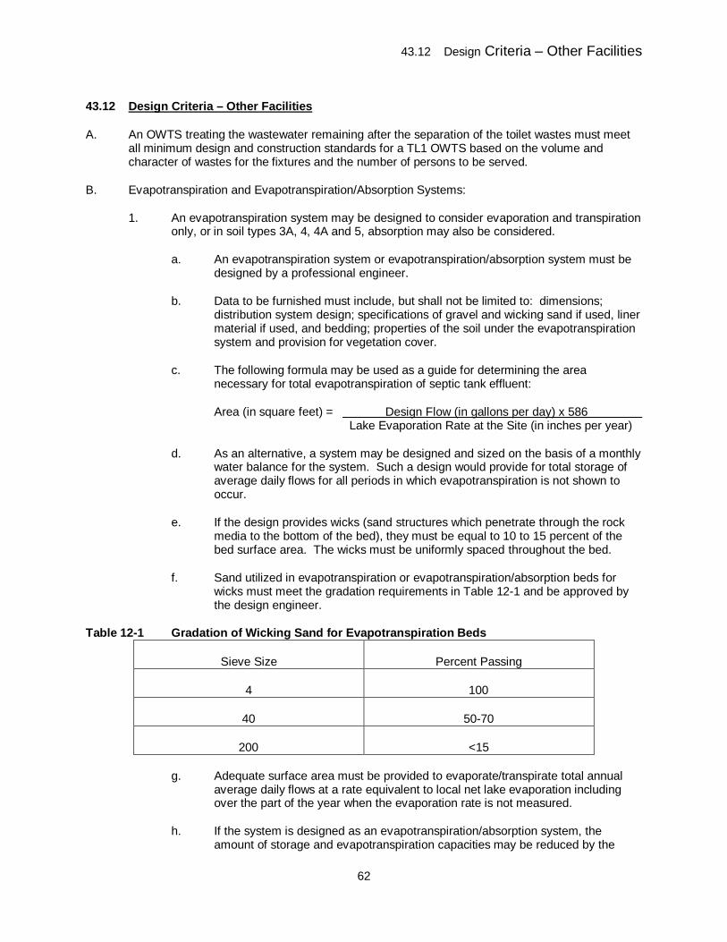
43.12 Design Criteria – Other Facilities
62
43.12 Design Criteria – Other Facilities
A. An OWTS treating the wastewater remaining after the separation of the toilet wastes must meet all minimum design and construction standards for a TL1 OWTS based on the volume and character of wastes for the fixtures and the number of persons to be served.
B. Evapotranspiration and Evapotranspiration/Absorption Systems:
1. An evapotranspiration system may be designed to consider evaporation and transpiration only, or in soil types 3A, 4, 4A and 5, absorption may also be considered.
a. An evapotranspiration system or evapotranspiration/absorption system must be designed by a professional engineer.
b. Data to be furnished must include, but shall not be limited to: dimensions; distribution system design; specifications of gravel and wicking sand if used, liner material if used, and bedding; properties of the soil under the evapotranspiration system and provision for vegetation cover.
c. The following formula may be used as a guide for determining the area necessary for total evapotranspiration of septic tank effluent:
Area (in square feet) = Design Flow (in gallons per day) x 586 Lake Evaporation Rate at the Site (in inches per year)
d. As an alternative, a system may be designed and sized on the basis of a monthly water balance for the system. Such a design would provide for total storage of average daily flows for all periods in which evapotranspiration is not shown to occur.
e. If the design provides wicks (sand structures which penetrate through the rock media to the bottom of the bed), they must be equal to 10 to 15 percent of the bed surface area. The wicks must be uniformly spaced throughout the bed.
f. Sand utilized in evapotranspiration or evapotranspiration/absorption beds for wicks must meet the gradation requirements in Table 12-1 and be approved by the design engineer.
Table 12-1 Gradation of Wicking Sand for Evapotranspiration Beds
Sieve Size Percent Passing
4 100
40 50-70
200 <15
g. Adequate surface area must be provided to evaporate/transpirate total annual average daily flows at a rate equivalent to local net lake evaporation including over the part of the year when the evaporation rate is not measured.
h. If the system is designed as an evapotranspiration/absorption system, the amount of storage and evapotranspiration capacities may be reduced by the
43.12 Design Criteria – Other Facilities
63
volume of effluent absorbed by the soil based on the long-term acceptance rate for that soil type.
i. Except for dwellings, if the system is designed for summer use only, as determined by the TCEH agency, the surface area may be multiplied by 0.6 to obtain the required area.
j. Evapotranspiration beds and evapotranspiration-absorption beds may be wider than 12 feet.
C. Wastewater Ponds
1. Construction of new wastewater ponds for single-family homes is prohibited.
2. A septic tank must precede the wastewater pond.
3. The depth of the design volume of the wastewater pond must be five feet.
4. A wastewater pond must have two feet of free board above the design volume of the pond.
5. A wastewater pond must be fenced to keep out livestock, pets, vermin, and unauthorized people.
6. Wastewater ponds must be designed on the basis of monthly water balance including design flow, precipitation, evaporation, and seepage.
7. Wastewater ponds must be constructed so the seepage out of the bottom or sides does not exceed 1/32 of an inch per day. If this limit cannot be achieved using compacted natural soil materials including soil additives, an impermeable synthetic membrane liner must be used.
8. Maintenance must include preventing aquatic and wetland plants from growing in or on the edge of the pond, protecting sides from erosion, and mowing grasses on the berm and around the pond.
9. Wastewater ponds must be designed by a professional engineer.
D. Vaults Other Than Vault Privies
1. Vaults for full time use in new construction are prohibited where a property can accommodate an OWTS with a soil treatment area.
2. The board of health may, by further adopted regulations, allow or prohibit vaults for use at a permanent facility, except where section 12.D.1. applies.
3. Vaults for full time use may be permitted when a failing OWTS cannot be replaced.
4. Vaults may be permitted for limited use occupancy on a property which cannot accommodate an OWTS with soil treatment area.
5. A vault may be permitted if the facility is on land where the installation of an OWTS with soil treatment area is not permitted.
43.12 Design Criteria – Other Facilities
64
6. Vaults may be permitted for systems where some of the wastewater flows are separated, such as toilet wastes only, into a vault. The portion not retained in the vault must be treated in an adequately-sized OWTS.
7. Variances may be granted for specialized commercial uses.
8. A vault, if permitted by the TCEH agency, must have a minimum 500 gallon effective volume or be capable of holding a minimum of the two-day design wastewater flow, whichever is larger.
9. A visual or an audible signal device or both, indicating filling to a maximum of 75 percent capacity, must be installed to indicate when pumping is necessary.
10. Concrete vaults must meet the strength and watertightness requirements for septic tanks. Prefabricated fiberglass, fiberglass-reinforced polyester, and plastic tanks may be used as vaults, if the tank manufacturer provides testing criteria certifying them for this use.
E. Privies
1. Vault Privy
a. The board of health may, by further adopted regulations, prohibit the new construction of vault privies.
b. The board of health may, by further adopted regulations, prohibit the continued use of existing vault privies.
c. Effective volume of the vault must be no less than 400 gallons and it must be constructed of concrete or plastic. The vaults for privies must meet the structural and watertightness standards of vaults.
d. A vault privy must be built to include: fly- and rodent-tight construction, a superstructure affording complete privacy, an earth mound around the top of the vault and below floor level that slopes downward away from the superstructure base, a floor, and a riser of concrete or other impervious material with hinged seats and covers of easily cleanable, impervious material. All venting must be fly-proofed with No. 16 or tighter mesh screening.
2. Pit Privy
a. The new and existing pit privies are prohibited.
F. Incinerating, Composting and Chemical Toilets
1. The board of health may permit incinerating, composting and chemical toilets.
2. Permitting of an incinerating or composting toilet may also be subject to the jurisdiction of Teller County regulating plumbing or the Colorado Plumbing Board, whichever has jurisdiction over plumbing in the location.
3. An incinerating or composting toilet may be used for toilet waste where an OWTS is installed for treating wastewater remaining after removal of toilet waste. Subject to the board of health or other applicable regulations or codes (e.g., Colorado Plumbing Code if a Teller County code does not exist), the compartment may be located within a dwelling or building provided the unit complies with the applicable requirements of this regulation,
43.12 Design Criteria – Other Facilities
65
and provided the installation will not result in conditions considered to be a health hazard as determined by the TCEH agency. Compartment and appurtenances related to the unit must include fly-tight and vector-proof construction and exterior ventilation.
4. Incinerating Toilets: An approved incinerating toilet must be designed and installed in accordance with all applicable federal, state, and local air-pollution requirements and manufacturer’s instructions.
5. Composting Toilets
a. An approved composting toilet must treat deposits of feces, urine, and readily decomposable household garbage that are not diluted with water or other fluids and are retained in a compartment in which aerobic composting will occur.
b. The effective volume of the receptacle must be sufficient to accommodate the number of persons served in the design of the unit installed. The effective volume of the unit must include sufficient area for the use of composting materials which must not be toxic to the process or hazardous to persons and which must be used in sufficient quantity to assure proper decomposition.
c. Residue from the composting toilet must be removed when it is filled to 75 percent of capacity. Residue from the unit must be properly disposed of by methods recommended by the manufacturer and acceptable to the TCEH agency. Disposal methods must prevent contamination of water and not cause a public health nuisance. Disposal using solid waste practices is recommended.
d. If a system will be installed where low temperature may be a factor, design and installation must address the effects of the low temperature.
e. Composting toilets must be operated according to manufacturer's specifications.
6. Portable Chemical Toilets
a. A portable chemical toilet may be used by permit from the TCEH agency or other agency with authority to issue permits for portable chemical toilets.
b. Use of a portable chemical toilet in permanently occupied buildings is prohibited except during construction or under emergency circumstances as determined by the TCEH agency. Proper ventilation of a chemical toilet used inside must be required.
G. Slit Trench Latrine
1. If permitted by the board of health, a slit trench latrine must be utilized only in remote or emergency situations when other approved sanitary means are unavailable. Other agencies may have more stringent regulations that must be adhered to.
2. A slit trench latrine must be considered a temporary convenience to be used no longer than seven days and must be backfilled and graded to match its surroundings when its use is discontinued.
3. A slit trench latrine must be located only in a place that does not adversely affect public health or the environment. The location must provide ample privacy and should be exposed to several hours of sunlight each day. A slit trench latrine must not be located:
43.12 Design Criteria – Other Facilities
66
a. In a building;
b. In a covered or partially covered location such as a cave or overhanging cliff; or
c. On a slope of greater than 30 percent.
4. A slit trench latrine must be installed only in suitable soil.
5. A slit trench latrine must be excavated approximately one foot wide and two feet deep for the required length. All human waste and tissue placed into the slit trench latrine must be covered with at least two inches of soil at least once a day or more frequently if requested by the TCEH agency.
H. Treatment Systems Other Than Those Discharging Through a Soil Treatment Area or Sand Filter System
1. For systems discharging to State Waters, see section 2.C.
2. Systems that discharge other than through a soil treatment area or a sand filter system must:
a. Be designed by a professional engineer;
b. Be reviewed by the board of health; and
c. Not pose a potential health hazard or private or public nuisance or undue risk of contamination.
3. The board of health may, by further adopted regulations, choose to permit only systems that do not allow drainage of effluent off the property of origin.
4. The following minimum performance criteria must be required for all permitted systems pursuant to this section:
a. If effluent discharge is made into areas in which the possibility exists for occasional direct human contact with the effluent discharge, the effluent at the point of discharge must meet the minimum treatment criteria of TL3 effluent and specifically adhere to each of the following standards:
(1) The geometric mean of the fecal coliform density must not exceed 25 per 100 milliliters when averaged over any five consecutive samples, and no single sample result for fecal coliform can exceed 200 per 100 milliliters.
(2) The arithmetic mean of the standard five-day carbonaceous biochemical oxygen demand (CBOD5) must not exceed ten milligrams per liter when averaged over any three consecutive samples.
(3) The arithmetic mean of the total suspended solids must not exceed ten milligrams per liter when averaged over any three consecutive samples.
b. If the effluent discharge is made into an area so restricted as to protect against the likelihood of direct human contact with the discharged effluent, the effluent at the point of discharge must meet the treatment criteria of TL2 effluent and specifically adhere to each of the following standards:
43.13 Technology Review and Acceptance
67
(1) The geometric mean of the fecal coliform density must not exceed 500 per 100 milliliters when averaged over any five consecutive samples, and no single sample can exceed 5000 fecal coliform per 100 milliliters.
(2) The arithmetic mean of the standard five-day carbonaceous biochemical oxygen demand (CBOD5) must not exceed 25 milligrams per liter when averaged over any three consecutive samples.
(3) The arithmetic mean of the total suspended solids must not exceed 30 milligrams per liter when averaged over any three consecutive samples.
5. To determine compliance with the standards contained in this section, the required sampling frequency for fecal coliform, CBOD5, and total suspended solid levels must be performed at least once per month when the system is in operation and the results submitted to the TCEH agency for compliance with the permit requirements.
6. Methods of Analysis - Sampling Points:
a. All effluent samples must be analyzed according to the methods prescribed in the American Public Health Association, American Water Works Association, and Water Environment Federation: Standards Methods for the Examination of Water and Wastewater, 21st edition.
b. The sampling point must be a location that is representative of final discharge from the system.
43.13 Technology Review and Acceptance
A. OWTS technologies must either be public domain, including but not limited to rock and pipe distribution systems, sand filters with pressure distribution and mound systems, with criteria for design, installation, maintenance and use as described in this regulation, or proprietary products that have received Division review and acceptance before the TCEH agency may permit them for use.
B. The Division must review and accept proprietary products in these technology categories:
1. Proprietary treatment products (e.g. treatment systems, remediation systems);
2. Propriety distribution products (e.g. manufactured distribution products or subsurface dripline);
3. Septic tanks;
4. Composting toilets;
5. Incinerating toilets; and
6. Others as needed.
C. Product Acceptance Requirements – General:
1. To qualify for product acceptance, manufacturers desiring to sell or distribute proprietary products in Colorado must submit a completed application to the Division in the format provided by the Division and a report describing in detail the test procedures and data confirming the performance and properties of the product claimed by the manufacturer.
43.13 Technology Review and Acceptance
68
Products within a single series or model line sharing distinct similarities in design, materials, capacities, configuration, and claiming the same level of treatment may be accepted under a single application. Products outside of the series or model line must be accepted under separate applications. The following information must be included in the application:
a. Manufacturer’s name, mailing address, street address, and phone number;
b. Contact individual’s name, mailing address, street address, phone number and email address. The contact individual must be vested with the authority to represent the manufacturer in the acceptance process;
c. Category of product (e.g., proprietary treatment product, proprietary distribution product, septic tank);
d. Name, including specific brand and model, of the proprietary product;
e. A description of the functions of the proprietary product, along with any known limitations on the use of the product;
f. Product description and technical information, including dimensioned drawings; materials and characteristics; component design specifications; and volumes, design capacity, and flow assumptions and calculations, as relevant;
g. Siting and installation requirements;
h. Product performance information in appropriate product section;
i. Detailed description, procedure and schedule of routine service and maintenance events;
j. Copies of manufacturer’s literature to include sales and promotion, design, installation, operation and maintenance, and owner instructions; and
k. Identification of information subject to protection from disclosure and trade secrets, if any.
2. Upon receipt of an application, the Division must verify that the application is complete and meets the requirements for which the product is being evaluated. If the application is found to be complete, and the requirements of this section needed to accept the product are met, the Division shall place the product on a list of accepted proprietary products for the type of product.
3. Manufacturers must have readily accessible and up to date information for designers, regulators, product owners, and other interested parties about their product including:
a. Product manuals;
b. Design instructions;
c. Installation instructions;
d. Operation and maintenance instructions; and
43.13 Technology Review and Acceptance
69
e. A list of representatives and manufacturer-certified service providers in Colorado, if any. If none exist, information on how service on the product will be provided in Colorado.
4. If, at any time after a proprietary product has been accepted for use, the Division receives information that the product so accepted does not meet the required standards, or in any way constitutes a public health or environmental hazard, the Division may, at its discretion, revoke the product acceptance. The Division shall notify the manufacturer and local public health agencies within 30 days of any revocation.
D. Proprietary Treatment Product Acceptance Requirements
1. If a proprietary treatment product is submitted to meet a specific treatment level, a report with test procedures and data must be submitted to the Division to demonstrate that it can meet the treatment level for which the approval is being requested on a consistent basis in actual installations. The Division must approve the test methods and programs. Test results from product certification testing must also be submitted.
2. If a product is accepted for a specific treatment level, the product may also be used for applications requiring lower treatment levels. Reductions based on higher level treatment may not be applied unless the TCEH agency has a maintenance oversight program in place as described in section 14.D.
3. Field Performance Testing
a. Testing must be performed by a neutral third party.
b. Testing for residential applications must be performed on a minimum of 12 single-family homes under normal operating conditions.
c. Each system must be tested over a period of at least one year.
d. Each system must be sampled at least four times during the year with the sampling evenly distributed throughout the year.
e. Laboratory results for all parameters for which acceptance is being requested must be submitted.
f. Testing may be performed in Colorado under a Product Development Permit.
g. Testing may be performed in locations other than Colorado, if elevation and climate conditions are similar to those in Colorado.
(1) Increased elevation results in lower atmospheric pressure and lower oxygen content. If components are changed or adjustments made to compensate for these conditions, those changes or adjustments must be specified.
(2) Colorado has a semi-arid climate. If components are changed or adjustments made to compensate for these conditions, those changes or adjustments must be specified.
(3) If nitrogen reduction is claimed, the provisions for nitrification at cold temperatures must be specified.
43.13 Technology Review and Acceptance
70
h. The report conclusions must indicate the proprietary treatment unit can consistently be expected to meet the treatment level for which acceptance is being requested.
i. The report must include estimated operating costs for the first five years of the treatment system’s life. This must include both estimated annual electricity or other energy costs, and routine inspection and maintenance costs, including replacement of parts.
(1) Energy and other costs are to be based on typical Denver, Colorado, costs at the time of the acceptance request.
(2) Replacement part costs must include shipping and handling.
(3) If media or other major part replacement is expected during the normal life of the system, the cost of replacement and the typical replacement interval must be included even if replacement is not expected within five years.
j. If a proprietary product has been accepted for use in Colorado under NSF/ANSI 40 or equivalent testing and at least one product unit has been installed in Colorado prior to the effective date of this regulation, the acceptance for use in Colorado may continue as treatment level 2.
E. Proprietary Distribution Product Acceptance Requirements
1. Proprietary manufactured distribution products must:
a. Be constructed or manufactured from materials that are non-decaying and non-deteriorating and do not leach chemicals when exposed to septic tank effluent and the subsurface soil environment;
b. Provide liquid storage volume at least equal to the storage volume within the assumed 30 percent void space in a rock and pipe distribution system assuming six inches of rock below the pipe and two inches above the pipe;
c. Maintain the integrity of the trench or bed. The material used, by its nature and its manufacturer-prescribed installation procedures, must withstand the physical forces of the soil sidewalls, soil backfill and the weight of equipment used in the backfilling; and
d. If the width of a proprietary manufactured distribution product is within 90 percent of the width of the excavation, it may be approved as being equivalent to the full width of the excavation, if information is provided that demonstrates distribution over the full width.
2. Proprietary subsurface dripline products must:
a. Be warranted by the manufacturer for use with OWTS effluent;
b. Specify required treatment level of influent to the driplines;
c. Be designed for resistance to root intrusion; and
43.13 Technology Review and Acceptance
71
d. Incorporate emitters that may be controlled either by use of pressure-compensation emitters or with a pressure regulator.
F. Proprietary Remediation Product Acceptance Requirements
1. Manufacturers of products for remediation of a soil treatment area must submit test data as described in field performance testing, section 13.D.3. demonstrating that the soil treatment area has been remediated for a period of at least three years.
2. Remediation must be demonstrated by showing that a soil treatment area that had been surfacing, does not surface again after use of the proprietary remediation product when the OWTS is operated under the same conditions as it was before the surfacing began.
3. Laboratory data may be submitted but will not take the place of field performance testing.
4. In addition to the field performance testing, the following additional requirements must be met for the appropriate situation.
a. For aeration or other higher level treatment installed following the septic tank, test data as described in field performance testing must be submitted demonstrating that the septic tank effluent strength has been reduced.
b. For aeration or other higher level treatment installed inside septic tank, test data as described in field performance testing must be submitted demonstrating that the septic tank effluent strength has been reduced and is lower than TL1.
c. For chemical and/or biological remediation, the chemicals or biological agents used in the remediation product must be demonstrated to have no negative effects on public health, environment, and soil properties. A material safety data sheet must be submitted, if available.
d. For physical remediation, the process used must be demonstrated to have no negative effects on public health, environment, and soil properties. The physical remediation process must not be repeated during the test time period.
G. Septic Tank Acceptance Requirements
1. Septic tank design must conform to the requirements of section 9.B. of this regulation.
2. Each manufacturer must test five percent of its tanks for watertightness at the manufacturing facility, unless the tanks are certified for use as a septic tank by the International Association of Plumbing and Mechanical Officials (IAPMO) or Canadian Standards Association (CSA), or the manufacturer participates in the Plant Certification Program of the National Precast Concrete Association (NPCA).
3. Watertightness results must be sent to the Division along with measures taken to repair a tank that fails the test and prevent similar problems in future tanks.
4. IAPMO, CSA, and NPCA certifications must be submitted to the Division for acceptance.
H. Composting Toilet Acceptance Requirements
1. Composting toilets must meet the requirements of NSF/ANSI Standard 41 and bear the seal of approval of the NSF or an equivalent testing and certification program.
43.14 Operation and Maintenance Requirements for Higher Level Treatment Systems
72
I. Incinerating Toilets Acceptance Requirements
1. Incinerating toilets must meet the requirements of the NSF Protocol P157 and bear the seal of approval of the NSF or an equivalent testing and certification program.
J. Other Product Acceptance Requirements
1. The Division may adopt review and acceptance requirements for additional products as needed.
43.14 Operation and Maintenance Requirements for Higher Level Treatment Systems
A. Responsibility: The owner must be responsible for maintenance of an OWTS unless the responsibility has been contractually assigned to a tenant or a third party or a public, quasi-public, or political subdivision.
B. Service Label: For higher level treatment systems or other components under a service contract, a clearly visible, permanently attached label or plate giving instructions for obtaining service must be placed at a conspicuous location.
C. The board of health may, by further adopted regulations, adopt regulations for:
1. Scheduling of maintenance and cleaning;
2. Practices adequate to ensure performance of an OWTS; and/or
3. Submission of proof of maintenance and cleaning to the TCEH agency by the owner of the system.
D. Permitting and Oversight of Maintenance for Soil Treatment Area Reductions and Vertical and Horizontal Separation Distance Reductions Based on Use of Higher Level Treatment
1. Purpose: Reductions in requirements for soil treatment areas, vertical separation distances to limiting layers or reductions in horizontal separation distances by using higher level treatment systems are based on the criteria that these systems are functioning as designed. If these criteria are not met, failure or malfunction is likely, which could result in damage to public health and water quality.
2. The board of health may, by further adopted regulations, choose to permit reductions in the size of soil treatment areas and horizontal and vertical separation distances based on higher level treatment of effluent, only if an oversight program for inspection, maintenance, and repair is implemented by the TCEH agency. Monitoring may be required.
3. The board of health is not required to allow reductions in soil treatment areas or vertical or horizontal separation distances based on higher level treatment. If these reductions are not allowed, the board of health is not required to implement section 14.D.
4. Before permitting systems with a reduced soil treatment area as a result of higher level treatment, TCEH agency must develop a program of inspections, maintenance, recordkeeping and enforcement to ensure and document that the systems are meeting the designed higher level treatment standards. At a minimum:
a. Maintain accessible records that indicate:
43.14 Operation and Maintenance Requirements for Higher Level Treatment Systems
73
(1) Owner and contact information;
(2) Address and legal description of property;
(3) Location of OWTS specifying location of septic tank, higher level treatment system, soil treatment area and other components;
(4) Description of OWTS installed;
(5) Level of treatment to be provided;
(6) Copy of current contract with a service provider;
(7) Inspection and maintenance performed:
(i) Dates system was inspected and/or maintained;
(ii) Name and contact information of inspector and/or maintenance provider;
(iii) Condition of system at inspection; and
(iv) Maintenance tasks performed;
(8) Permits, if required by the TCEH agency for the work performed; and
(9) Condition of system at completion of any maintenance activity.
b. Frequency of inspection and maintenance must be the most frequent of:
(1) Manufacturer recommendations for proprietary systems or design criteria requirements for public domain technology;
(2) TCEH agency or Division requirements;
(3) Every six months for higher level treatment systems with mechanical parts; or
(4) Every 12 months for higher level treatment systems with no mechanical parts.
c. Owner responsibilities:
(1) Ensure OWTS is operating, maintained and performing according to the required standards for the designated treatment level;
(2) Maintain an active service contract with a maintenance provider at all times; and
(3) Each time his/her current contract with a maintenance provider is renewed or replaced, send a copy to the TCEH agency within 30 days of signing.
E. Monitoring and Sampling
43.15 Severability
74
1. For an OWTS for which monitoring of effluent is required, the TCEH agency or delegated third party must collect and test effluent samples to ensure compliance with the provisions of this regulation.
2. Sampling may be required by the TCEH agency in conjunction with an enforcement action.
3. Any owner or occupant of property on which an OWTS is located may request the TCEH agency to collect and test an effluent sample from the system. The TCEH agency may perform such collection and testing services. The owner or occupant must pay for these services.
a. If the TCEH agency or a delegated third party collects and tests effluent samples, a fee not to exceed that which is allowed by the OWTS Act may be charged for each sample collected and tested. Payment of such charge must be stated in the permit as a condition for its continued use.
b. Conditions when TCEH agency can require routine monitoring:
(1) Indications of inadequate performance;
(2) Location in sensitive areas;
(3) Experimental systems; and/or
(4) Systems under product development permits.
c. Sampling and analysis must be performed according to American Public Health Association, American Water Works Association, and Water Environment Federation: Standards Methods for the Examination of Water and Wastewater, 21st edition.
43.15 Severability
The provisions of this regulation are severable, and if any provisions or the application of the provisions to any circumstances are held invalid, the application of such provision to other circumstances, and the remainder of this regulation shall not be affected thereby.
43.16 Materials Incorporated by Reference
Throughout these regulations, standards and requirements by outside organizations have been adopted and incorporated by reference. The materials incorporated by reference cited herein include only those versions that were in effect as of June 30, 2013 and not later amendments to the incorporated material.
Materials incorporated by reference are available for public inspection during normal business hours from the Water Quality Control Division, 4300 Cherry Creek Drive South, Denver, Colorado 80246. Copies may be purchased from the source organizations.
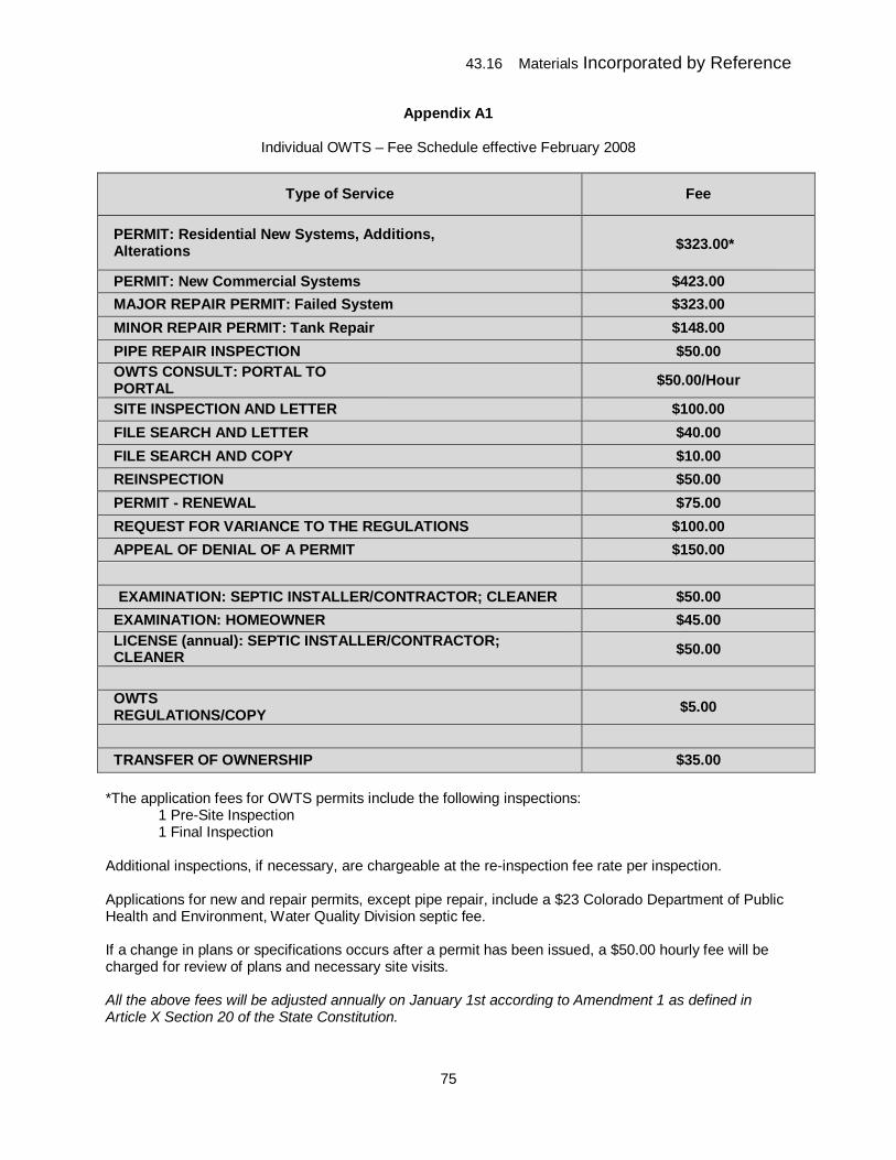
43.16 Materials Incorporated by Reference
75
Appendix A1
Individual OWTS – Fee Schedule effective February 2008
Type of Service Fee
PERMIT: Residential New Systems, Additions, Alterations
$323.00*
PERMIT: New Commercial Systems
$423.00 MAJOR REPAIR PERMIT: Failed System
$323.00 MINOR REPAIR PERMIT: Tank Repair
$148.00 PIPE REPAIR INSPECTION
$50.00 OWTS CONSULT: PORTAL TO PORTAL
$50.00/Hour
SITE INSPECTION AND LETTER
$100.00 FILE SEARCH AND LETTER
$40.00 FILE SEARCH AND COPY
$10.00 REINSPECTION
$50.00 PERMIT - RENEWAL
$75.00 REQUEST FOR VARIANCE TO THE REGULATIONS
$100.00 APPEAL OF DENIAL OF A PERMIT
$150.00 EXAMINATION: SEPTIC INSTALLER/CONTRACTOR; CLEANER
$50.00 EXAMINATION: HOMEOWNER
$45.00 LICENSE (annual): SEPTIC INSTALLER/CONTRACTOR; CLEANER
$50.00
OWTS REGULATIONS/COPY
$5.00
TRANSFER OF OWNERSHIP
$35.00 *The application fees for OWTS permits include the following inspections:
1 Pre-Site Inspection 1 Final Inspection
Additional inspections, if necessary, are chargeable at the re-inspection fee rate per inspection. Applications for new and repair permits, except pipe repair, include a $23 Colorado Department of Public Health and Environment, Water Quality Division septic fee. If a change in plans or specifications occurs after a permit has been issued, a $50.00 hourly fee will be charged for review of plans and necessary site visits. All the above fees will be adjusted annually on January 1st according to Amendment 1 as defined in Article X Section 20 of the State Constitution.
43.16 Materials Incorporated by Reference
76
Appendix B1 The Health Officer may consider the installation of a septic system and dwelling or structure on separate parcels in the following situations: 1. In order to establish the Ute Lakes Environmental Health Overlay Zone, dwellings and individual sewage disposal systems may be approved on separate parcels on the parcels described in the Vacation Plat of Ute Lakes Club as recorded in the records of Teller County, Colorado in Plat Book G, Pages 139-141 and as amended by the Subdivision Exemption Plat of Lots 3&4, Block D Ute Lakes Subdivision #1 recorded in the records of Teller County, Colorado under Reception No. 49787, as well as the balance of property described as the South half of the Northwest quarter, the South half of the Northeast quarter, the Northeast quarter and that portion of the South half of said section 18 lying North of the following described line: Commencing at the Southwest corner of said section 18, run thence Northerly along the West line of Said section 18, 2283.89 feet to the point of beginning of the line hereby described; Thence angle right 93° 00' 19" Easterly, 3468.48 feet; thence angle right 86° 46' 45" Easterly, 700.00 feet; Thence angle left 93° 13' 15" Northerly, 373.77 feet; thence angle right 64° 12' 50" Northeasterly, 618.17 feet; thence angle right 29° 00' 25" Easterly, 635.00 feet to intersect the East line of said 18 at a point 2479.22 feet Northerly on said East line from the southeast corner of said section 18, (a.k.a. Ute Lakes Subdivision). The following stipulations apply: A. OWTS permits will be considered only for owners of parcels in the Ute Lakes Subdivision
who wish to install their OWTS on Ute Lakes Fishing and Recreation Club, Inc., property. B. OWTS permits will be considered only on parcels for which site constraints prohibit the
installation of the structure and the septic system on the same parcel, and, only on parcels created prior to December 2001.
C. The accumulation of all OWTS discharges onto any one parcel shall not exceed 2000
gallons per day average flow. If the accumulated average flow of all systems located on any one parcel exceeds 2000 gallons per day, a site application and approval from the Colorado Department of Health and Environment, Water Quality Division shall be required. The application shall be submitted in accordance with these regulations.
D. A Teller County OWTS permit shall be obtained and a permit application submitted as
per these regulations. The application shall include written approval from the Ute Lakes fishing Club for use of their property. The approval shall include a provision that will allow the parcel owner to comply with these regulations. This agreement shall be notarized and recorded.
E. Land use and environmental overlay zone requirements shall be met. F. The owner of the structure to which the OWTS is connected shall be responsible for
operating and maintaining the OWTS in accordance with these regulations. G. All other requirements of these OWTS regulations apply.