tooling systems cartridges - 住友電工ハードメタル事業 … · 2017-03-09 · boring...
TRANSCRIPT
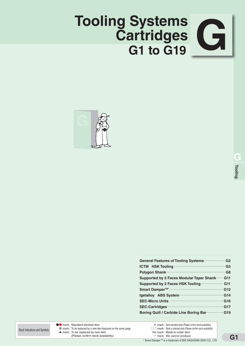
G1
G
General Features of Tooling Systems ......................G2
ICTM HSK Tooling .....................................................G3
Polygon Shank .............................................................G8
Supported by 2 Faces Modular Taper Shank ....... G11
Supported by 2 Faces HSK Tooling ....................... G11
Smart DamperTM* ........................................................G12
Igetalloy ABS System .............................................G14
SEC-Micro Units ........................................................G16
SEC-Cartridges ..........................................................G17
Boring Quill / Carbide Line Boring Bar .................G19
G1 to G19 GTooling Systems
Cartridges
●● mark: Standard stocked item
● mark: To be replaced by a new item featured on the same page
▲ mark: To be replaced by new item (Please confirm stock availability)
* mark: Semi-standard stock (Please confirm stock availability)
○○ mark: Stock or planned stock (Please confirm stock availability) No mark: Made-to-order item
- mark: We cannot produce
Stock Indications and Symbols
To
olin
g
* Smart Damper TM is a trademark of BIG DAISHOWA SEIKI CO., LTD.
G
G2
G
To
olin
g
For
Turn
ing
For
Mill
ing
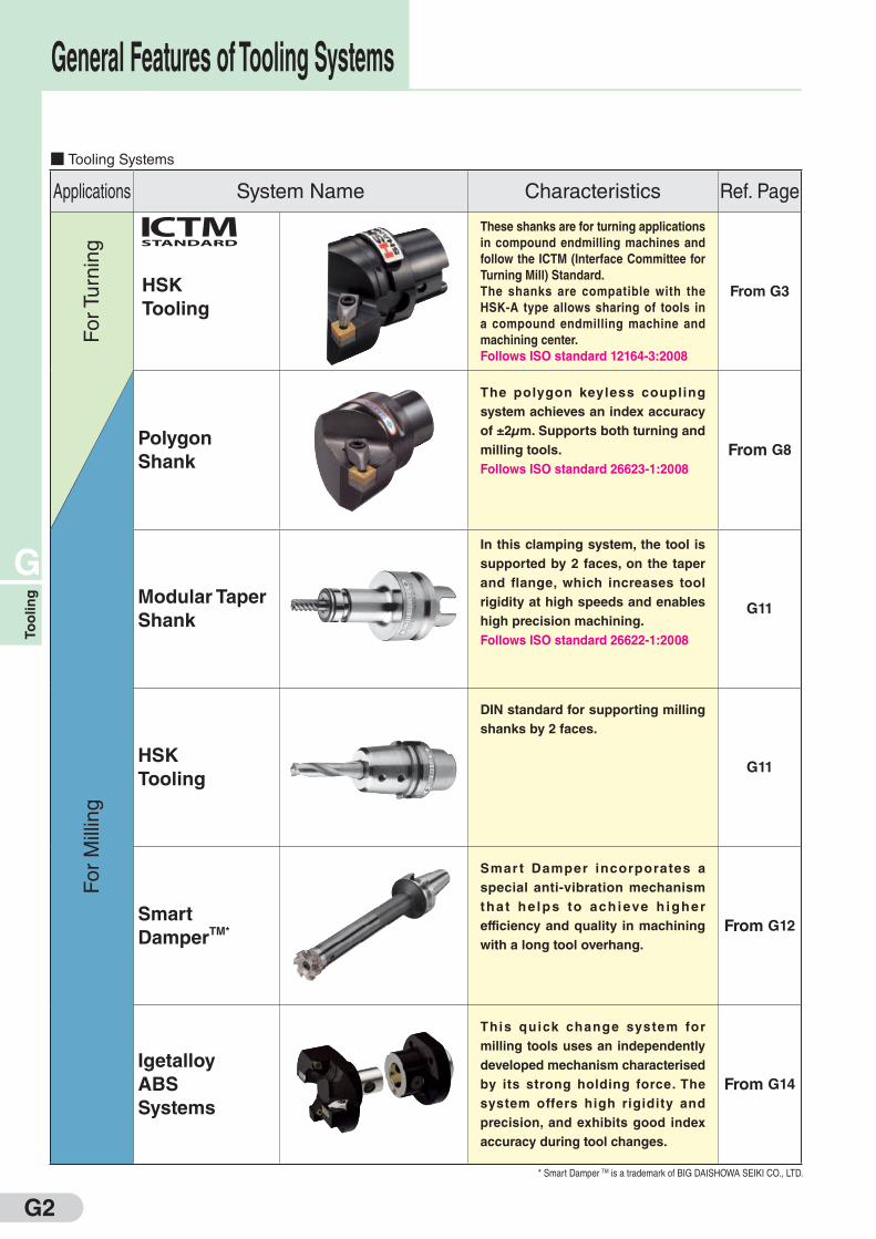
■ Tooling Systems
Applications System Name Characteristics Ref. Page
HSK
Tooling
These shanks are for turning applications
in compound endmilling machines and
follow the ICTM (Interface Committee for
Turning Mill) Standard.
The shanks are compatible with the
HSK-A type allows sharing of tools in
a compound endmilling machine and
machining center.
Follows ISO standard 12164-3:2008
From G3
Polygon
Shank
The polygon keyless coupling
system achieves an index accuracy
of ±2μm. Supports both turning and
milling tools.
Follows ISO standard 26623-1:2008
From G8
Modular Taper
Shank
In this clamping system, the tool is
supported by 2 faces, on the taper
and flange, which increases tool
rigidity at high speeds and enables
high precision machining.
Follows ISO standard 26622-1:2008
G11
HSK
Tooling
DIN standard for supporting milling
shanks by 2 faces.
G11
Smart
DamperTM*
Smart Damper incorporates a
special anti-vibration mechanism
that he lps to ach ieve h igher
efficiency and quality in machining
with a long tool overhang.
From G12
Igetalloy
ABS
Systems
This quick change system for
milling tools uses an independently
developed mechanism characterised
by its strong holding force. The
system offers high rigidity and
precision, and exhibits good index
accuracy during tool changes.
From G14
General Features of Tooling Systems
* Smart Damper TM is a trademark of BIG DAISHOWA SEIKI CO., LTD.

G3
G
To
olin
g
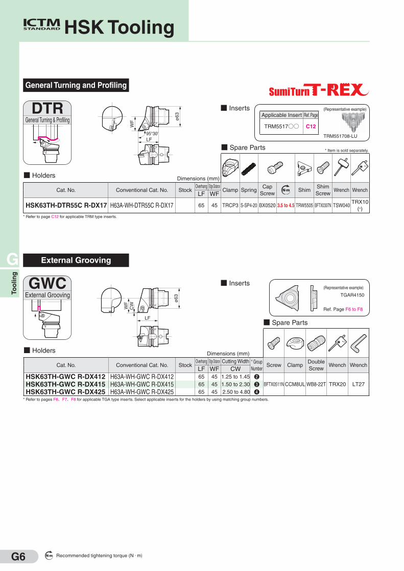
■ General Features
The HSK tooling system has been adopted by Japanese 17 major
machine tool manufacturers as the interface for turning tools in
compound endmilling machines. It is based on the ICTM (Interface
Committee for Turning Mill) standard.
Based on the ISO standard HSK shank, this standard attempts to
improve precision in turning applications, and maintains compatibility
with the HSK-A type in widespread use on machining centers.
* Catalog numbers have been changed due to ISO standardisation (ISO
12164-3:2008).
For support with non-standard specifications, contact us directly.
General Turning and Facing
■ Spare Parts * Item is sold separately.
■ Holders Above figures show right hand tools.
Cat. No. Conventional Cat. No.Stock Overhang Edge Distance
Clamp Set N m ShimShim
Screw
Shim
WrenchWrench
R L LF WF
HSK63TH-DCLN R/L-DX12 H63A-WH-DCLN R/L-DX12 65 45 SCP-2 5.0 CNS1204 BFTX0409NTRX15
(*)LH040
■ Spare Parts * Item is sold separately.
■ Holders
Cat. No. Conventional Cat. No. StockOverhang
Clamp Set N m ShimShim
Screw
Shim
WrenchWrench
LF
HSK63TH-DCMN N-H12 H63A-WH-DCMN N-H12 100SCP-2 5.0 CNS1204 BFTX0409N
TRX15
(*)LH040
HSK63TH-DCMN N-L12 H63A-WH-DCMN N-L12 140
■ InsertsDCLNGeneral Turning & Facing
LF95°
80°
WF ø
63
DCMNGeneral Turning & Facing
LF50°
ø6380° ■ Inserts
CNMG120408N-GE
Applicable Insert Ref. Page
CN□□1204○○ FromB22
(Representative example)
CNMG120408N-GE
Applicable Insert Ref. Page
CN□□1204○○ FromB22
(Representative example)
HSK Tooling
Dimensions (mm)
Dimensions (mm)
Recommended tightening torque (N・m)
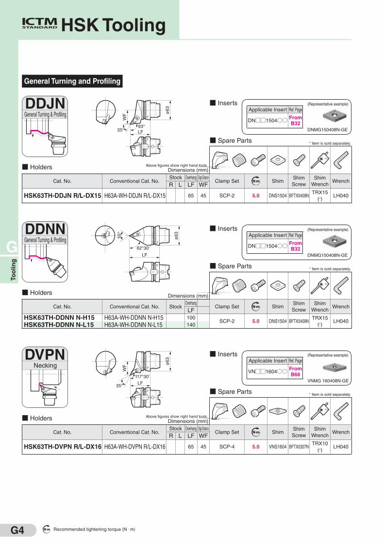
G4
G
To
olin
g
■ Spare Parts * Item is sold separately.
■ Holders Above figures show right hand tools.
Cat. No. Conventional Cat. No.Stock Overhang Edge Distance
Clamp Set N m ShimShim
Screw
Shim
WrenchWrench
R L LF WF
HSK63TH-DDJN R/L-DX15 H63A-WH-DDJN R/L-DX15 65 45 SCP-2 5.0 DNS1504 BFTX0409NTRX15
(*)LH040
■ Inserts
■ Spare Parts * Item is sold separately.
■ Holders
Cat. No. Conventional Cat. No. StockOverhang
Clamp Set N m ShimShim
Screw
Shim
WrenchWrench
LF
HSK63TH-DDNN N-H15 H63A-WH-DDNN N-H15 100SCP-2 5.0 DNS1504 BFTX0409N
TRX15
(*)LH040
HSK63TH-DDNN N-L15 H63A-WH-DDNN N-L15 140
■ Spare Parts * Item is sold separately.
■ Holders Above figures show right hand tools.
Cat. No. Conventional Cat. No.Stock Overhang Edge Distance
Clamp Set N m ShimShim
Screw
Shim
WrenchWrench
R L LF WF
HSK63TH-DVPN R/L-DX16 H63A-WH-DVPN R/L-DX16 65 45 SCP-4 5.0 VNS1604 BFTX0307NTRX10
(*)LH040
■ Inserts
General Turning and Profiling
DDJNGeneral Turning & Profiling
LF93°
55°WF ø
63
■ InsertsDDNNGeneral Turning & Profiling
LF
62°30'
ø6355°
DVPNNecking
LF
117°30'
WF ø
63
35°
DNMG150408N-GE
Applicable Insert Ref. Page
DN□□1504○○ FromB32
(Representative example)
DNMG150408N-GE
Applicable Insert Ref. Page
DN□□1504○○ FromB32
(Representative example)
VNMG 160408N-GE
Applicable Insert Ref. Page
VN□□1604○○ FromB66
(Representative example)
HSK Tooling
Dimensions (mm)
Dimensions (mm)
Dimensions (mm)
Recommended tightening torque (N・m)
G5
G
To
olin
g
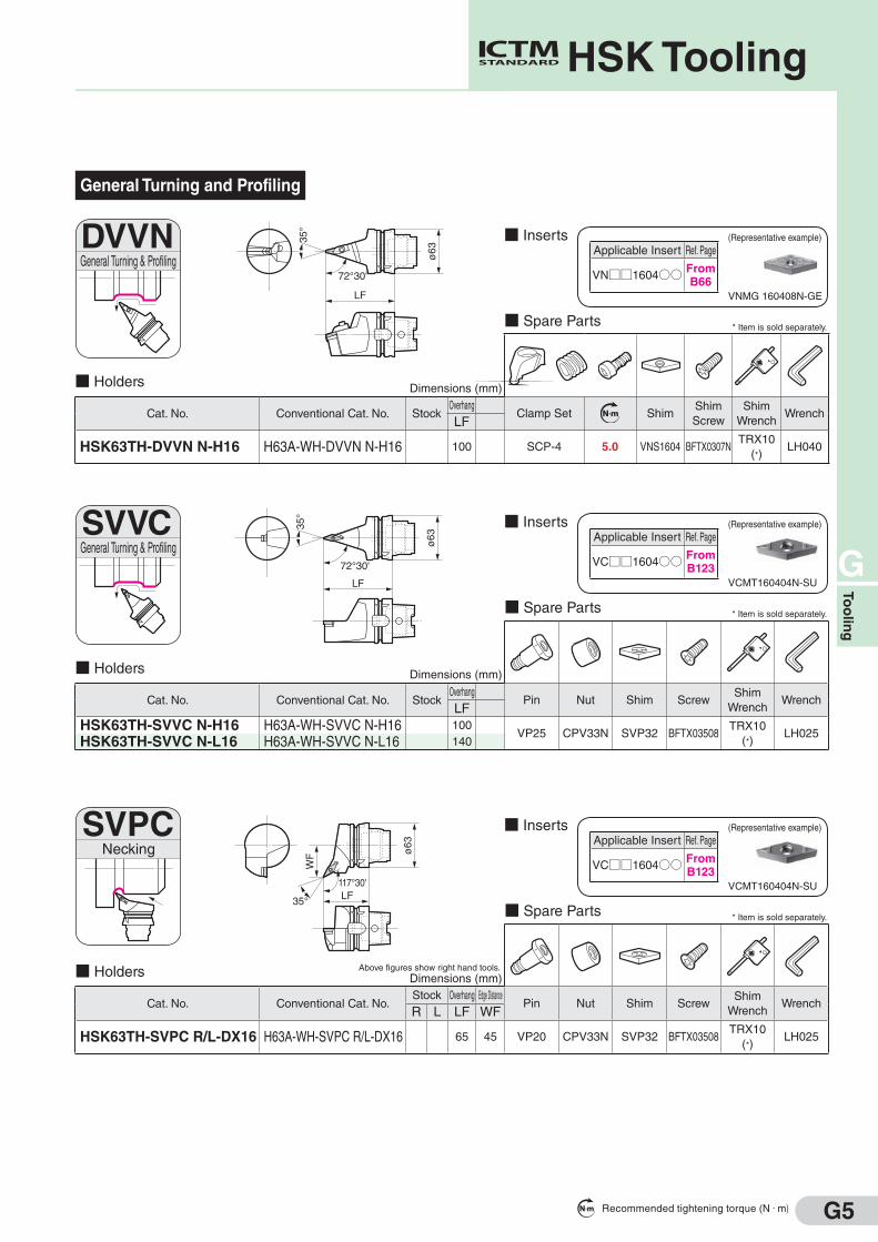
General Turning and Profiling
■ Spare Parts * Item is sold separately.
■ Holders
Cat. No. Conventional Cat. No. StockOverhang
Clamp Set N m ShimShim
Screw
Shim
WrenchWrench
LF
HSK63TH-DVVN N-H16 H63A-WH-DVVN N-H16 100 SCP-4 5.0 VNS1604 BFTX0307NTRX10
(*)LH040
■ Spare Parts * Item is sold separately.
■ Holders
Cat. No. Conventional Cat. No. StockOverhang
Pin Nut Shim ScrewShim
WrenchWrench
LF
HSK63TH-SVVC N-H16 H63A-WH-SVVC N-H16 100VP25 CPV33N SVP32 BFTX03508
TRX10
(*)LH025
HSK63TH-SVVC N-L16 H63A-WH-SVVC N-L16 140
■ Inserts
■ Spare Parts * Item is sold separately.
■ Holders Above figures show right hand tools.
Cat. No. Conventional Cat. No.Stock Overhang Edge Distance
Pin Nut Shim ScrewShim
WrenchWrench
R L LF WF
HSK63TH-SVPC R/L-DX16 H63A-WH-SVPC R/L-DX16 65 45 VP20 CPV33N SVP32 BFTX03508TRX10
(*)LH025
■ InsertsDVVNGeneral Turning & Profiling
LF
72°30'
ø63
35°
SVVCGeneral Turning & Profiling
LF
72°30'
ø63
35°
SVPCNecking
LF117°30'
WF ø
63
35°
■ Inserts
VNMG 160408N-GE
Applicable Insert Ref. Page
VN□□1604○○ FromB66
(Representative example)
VCMT160404N-SU
Applicable Insert Ref. Page
VC□□1604○○ FromB123
(Representative example)
VCMT160404N-SU
Applicable Insert Ref. Page
VC□□1604○○ FromB123
(Representative example)
HSK Tooling
Dimensions (mm)
Dimensions (mm)
Dimensions (mm)
Recommended tightening torque (N・m)
G6
G
To
olin
g
General Turning and Profiling
■ Spare Parts * Item is sold separately.
■ Holders
Cat. No. Conventional Cat. No. StockOverhang Edge Distance
Clamp SpringCap
ScrewN m Shim
Shim
ScrewWrench Wrench
LF WF
HSK63TH-DTR55C R-DX17 H63A-WH-DTR55C R-DX17 65 45 TRCP3 S-SP4-20 BX0520 3.5 to 4.5 TRW5505 BFTX0307N TSW040TRX10
(*)
* Refer to page C12 for applicable TRM type inserts.
■ Inserts
External Grooving
■ Spare Parts
■ Holders
Cat. No. Conventional Cat. No. StockOverhang Edge Distance Cutting Width * Group
NumberScrew Clamp
Double
ScrewWrench Wrench
LF WF CW
HSK63TH-GWC R-DX412 H63A-WH-GWC R-DX412 65 45 1.25 to 1.45 ❷BFTX0511N CCM8UL WB8-22T TRX20 LT27HSK63TH-GWC R-DX415 H63A-WH-GWC R-DX415 65 45 1.50 to 2.30 ❸
HSK63TH-GWC R-DX425 H63A-WH-GWC R-DX425 65 45 2.50 to 4.80 ❹* Refer to pages F6、F7、F8 for applicable TGA type inserts. Select applicable inserts for the holders by using matching group numbers.
■ Inserts
TGAR4150
General Turning & ProfilingDTR
ø63
LF95°30'
WF
GWCExternal Grooving
LF
CW
WF ø
63
Applicable Insert Ref. Page
TRM5517○○ C12
TRM551708-LU
(Representative example)
(Representative example)
Ref. Page F6 to F8
HSK Tooling
Dimensions (mm)
Dimensions (mm)
Recommended tightening torque (N・m)
G7
G
To
olin
g
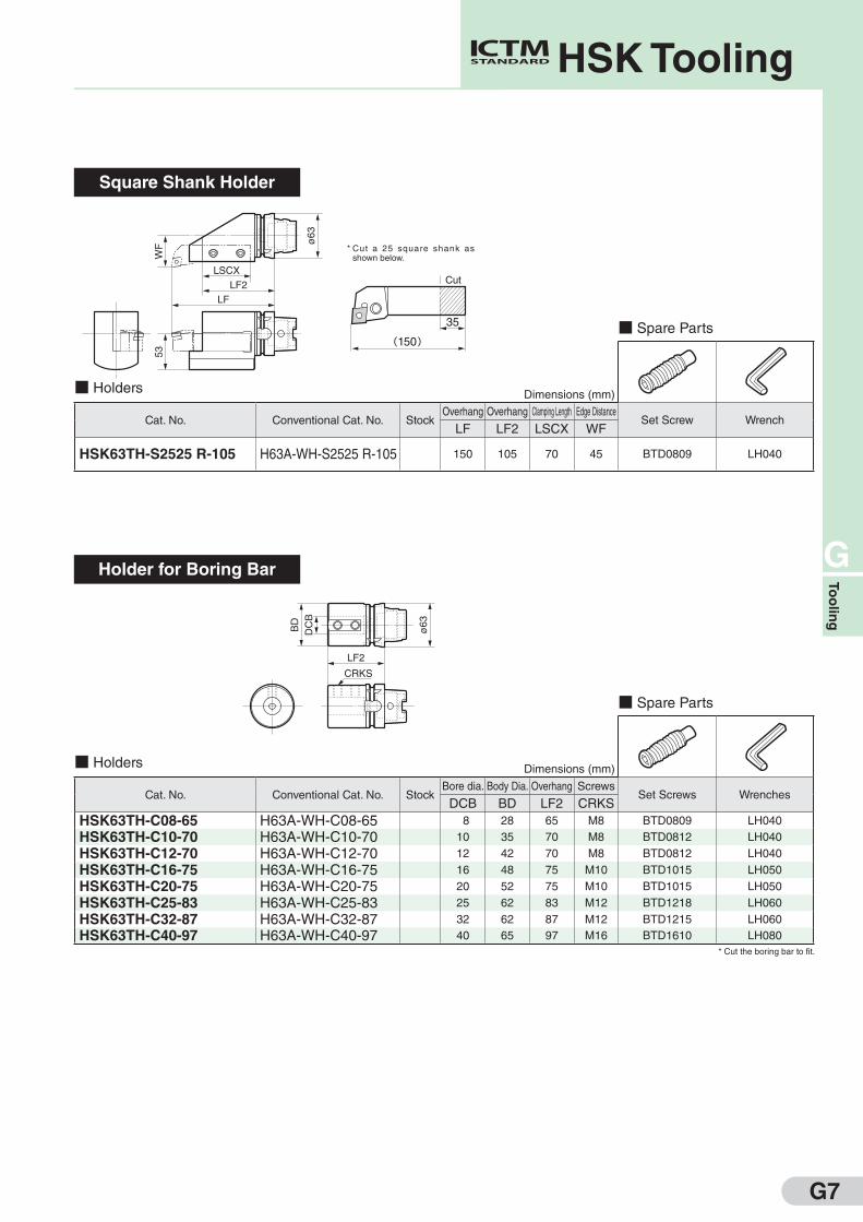
Square Shank Holder
Holder for Boring Bar
■ Spare Parts
■ Holders
Cat. No. Conventional Cat. No. StockBore dia. Body Dia. Overhang Screws
Set Screws WrenchesDCB BD LF2 CRKS
HSK63TH-C08-65 H63A-WH-C08-65 8 28 65 M8 BTD0809 LH040
HSK63TH-C10-70 H63A-WH-C10-70 10 35 70 M8 BTD0812 LH040
HSK63TH-C12-70 H63A-WH-C12-70 12 42 70 M8 BTD0812 LH040
HSK63TH-C16-75 H63A-WH-C16-75 16 48 75 M10 BTD1015 LH050
HSK63TH-C20-75 H63A-WH-C20-75 20 52 75 M10 BTD1015 LH050
HSK63TH-C25-83 H63A-WH-C25-83 25 62 83 M12 BTD1218 LH060
HSK63TH-C32-87 H63A-WH-C32-87 32 62 87 M12 BTD1215 LH060
HSK63TH-C40-97 H63A-WH-C40-97 40 65 97 M16 BTD1610 LH080
* Cut the boring bar to fit.
■ Spare Parts
■ Holders
Cat. No. Conventional Cat. No. StockOverhang Overhang Clamping Length Edge Distance
Set Screw WrenchLF LF2 LSCX WF
HSK63TH-S2525 R-105 H63A-WH-S2525 R-105 150 105 70 45 BTD0809 LH040
LF2
LF
LSCX
WF
53
ø6
3
(150)
35
Cut
* Cut a 25 square shank as shown below.
LF2
CRKS
DC
BB
D
ø63
HSK Tooling
Dimensions (mm)
Dimensions (mm)
G8
G
To
olin
g
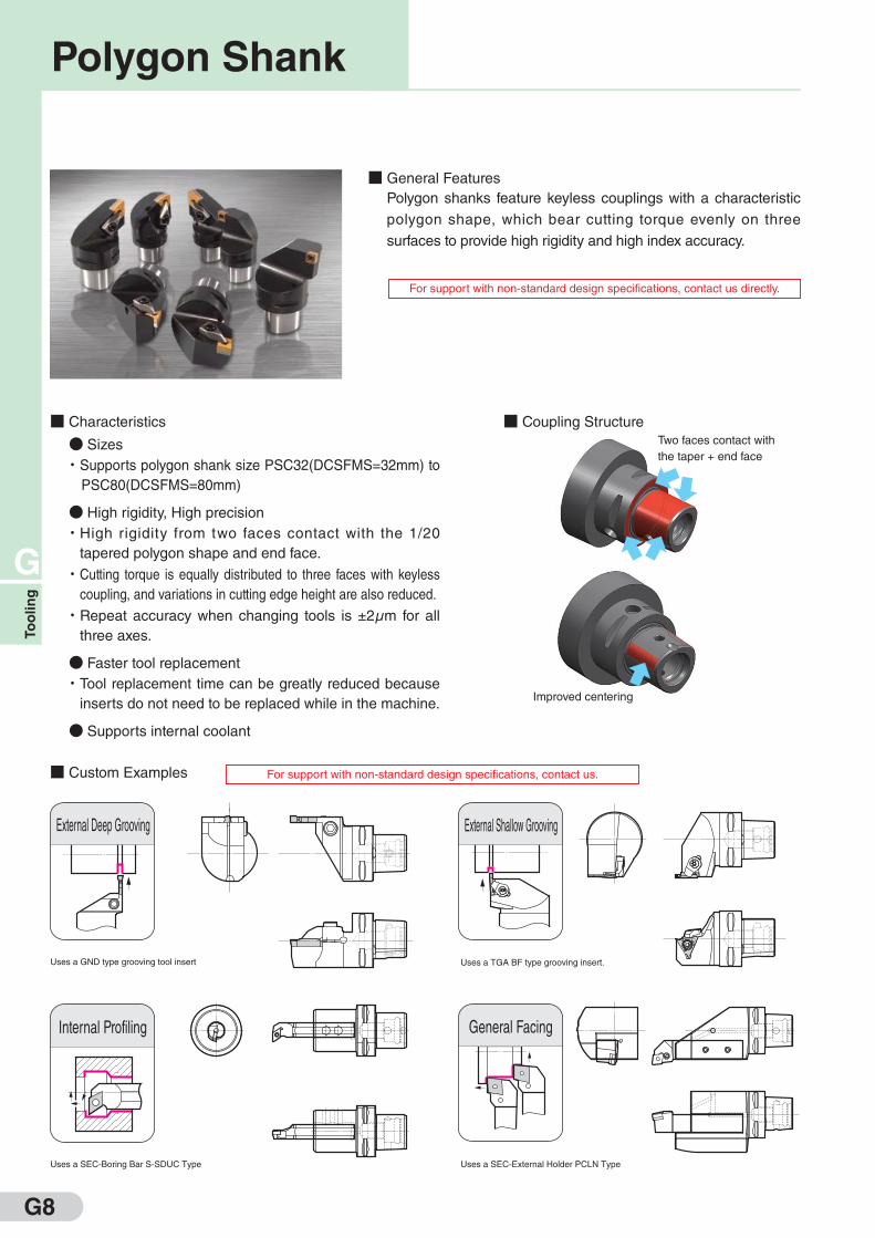
■ General Features
Polygon shanks feature keyless couplings with a characteristic
polygon shape, which bear cutting torque evenly on three
surfaces to provide high rigidity and high index accuracy.
■ Custom Examples For support with non-standard design specifications, contact us.
For support with non-standard design specifications, contact us directly.
■ Characteristics
● Sizes
・Supports polygon shank size PSC32(DCSFMS=32mm) to
PSC80(DCSFMS=80mm)
● High rigidity, High precision
・ High rigidity from two faces contact with the 1/20
tapered polygon shape and end face.
・ Cutting torque is equally distributed to three faces with keyless
coupling, and variations in cutting edge height are also reduced.
・ Repeat accuracy when changing tools is ±2μm for all
three axes.
● Faster tool replacement
・ Tool replacement time can be greatly reduced because
inserts do not need to be replaced while in the machine.
● Supports internal coolant
■ Coupling StructureTwo faces contact with
the taper + end face
Improved centering
External Shallow Grooving
Internal Profiling
Uses a SEC-Boring Bar S-SDUC Type
General Facing
Uses a SEC-External Holder PCLN Type
External Deep Grooving
Uses a GND type grooving tool insert Uses a TGA BF type grooving insert.
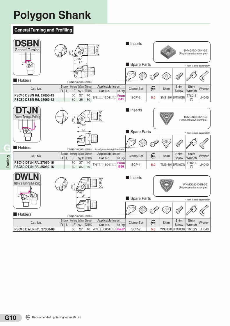
Polygon Shank
G
To
olin
g
G9
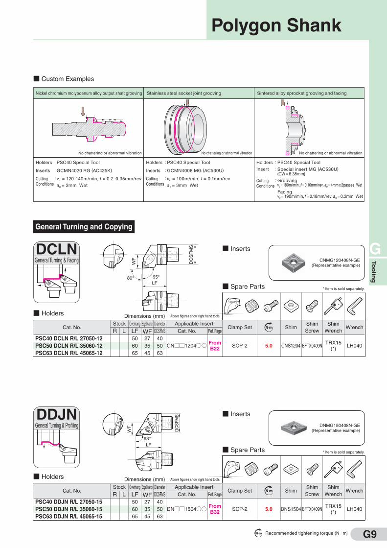
General Turning and Copying
■ Spare Parts * Item is sold separately.
■ Holders Above figures show right hand tools.
Cat. No.Stock Overhang Edge Distance Diameter Applicable Insert
Clamp Set N m ShimShim
Screw
Shim
WrenchWrench
R L LF WF DCSFMS Cat. No. Ref. Page
PSC40 DCLN R/L 27050-12 50 27 40
CN□□1204○○ FromB22
SCP-2 5.0 CNS1204 BFTX0409NTRX15
(*)LH040PSC50 DCLN R/L 35060-12 60 35 50
PSC63 DCLN R/L 45065-12 65 45 63
■ Inserts
■ Spare Parts * Item is sold separately.
■ Holders Above figures show right hand tools.
Cat. No.Stock Overhang Edge Distance Diameter Applicable Insert
Clamp Set N m ShimShim
Screw
Shim
WrenchWrench
R L LF WF DCSFMS Cat. No. Ref. Page
PSC40 DDJN R/L 27050-15 50 27 40
DN□□1504○○ FromB32
SCP-2 5.0 DNS1504 BFTX0409NTRX15
(*)LH040PSC50 DDJN R/L 35060-15 60 35 50
PSC63 DDJN R/L 45065-15 65 45 63
■ Inserts
DCLNGeneral Turning & Facing
LF95°80°
WF
DCSFMS
DDJNGeneral Turning & Profiling
WF
DCSFM
S
LF93°
CNMG120408N-GE(Representative example)
DNMG150408N-GE(Representative example)
Nickel chromium molybdenum alloy output shaft grooving
Holders
Inserts
Cutting Conditions
:
:
:
PSC40 Special Tool
GCMN4020 RG (AC425K)
vc = 120-140m/min, f = 0.2-0.35mm/revap = 2mm Wet
No chattering or abnormal vibration
Stainless steel socket joint grooving
Holders
Inserts
Cutting Conditions
:
:
:
PSC40 Special Tool
GCMN4008 MG (AC530U)
vc = 100m/min, f = 0.1mm/revap = 3mm Wet
No chattering or abnormal vibration
Sintered alloy sprocket grooving and facing
Holders
Insert
Cutting Conditions
::
:
PSC40 Special Tool
Special insert MG (AC530U)(CW = 6.35mm)
Groovingvc = 180m/min, f = 0.16mm/rev, ap = 4mm x 2passes Wet
Facingvc = 190m/min, f = 0.18mm/rev, ap = 0.2mm Wet
No chattering or abnormal vibration
■ Custom Examples
Polygon Shank
Dimensions (mm)
Dimensions (mm)
Recommended tightening torque (N・m)
G10
G
To
olin
g
General Turning and Profiling
■ Spare Parts * Item is sold separately.
■ Holders
Cat. No.Stock Overhang Edge Distance Diameter Applicable Insert
Clamp Set N m ShimShim
Screw
Shim
WrenchWrench
R L LF WF DCSFMS Cat. No. Ref. Page
PSC40 DSBN R/L 27050-12 50 27 40SN□□1204○○ From
B41SCP-2 5.0 SNS1204 BFTX0409N
TRX15(*)
LH040PSC50 DSBN R/L 35060-12 60 35 50
■ InsertsDSBNGeneral Turning
WF
DCSFM
S
LF75°
SNMG120408N-GE(Representative example)
■ Spare Parts * Item is sold separately.
■ Holders Above figures show right hand tools.
Cat. No.Stock Overhang Edge Distance Diameter Applicable Insert
Clamp Set N m ShimShim
Screw
Shim
WrenchWrench
R L LF WF DCSFMS Cat. No. Ref. Page
PSC40 DTJN R/L 27050-16 50 27 40TN□□1604○○ From
B56SCP-1 5.0 TNS1604 BFTX0307N
TRX15(*)
LH040PSC50 DTJN R/L 35060-16 60 35 50
■ InsertsDTJNGeneral Turning & Profiling
WF
DCSFM
S
LF
93°
TNMG160408N-GE(Representative example)
■ Spare Parts * Item is sold separately.
■ Holders
Cat. No.Stock Overhang Edge Distance Diameter Applicable Insert
Clamp Set N m ShimShim
Screw
Shim
WrenchWrench
R L LF WF DCSFMS Cat. No. Ref. Page
PSC40 DWLN R/L 27050-08 50 27 40 WN□□0804○○ From B71 SCP-2 5.0 WNS0804 BFTX0409N TRX15(*) LH040
■ InsertsDWLNGeneral Turning & Facing
WF
DCSFM
S
LF95°
WNMG080408N-SE(Representative example)
Polygon Shank
Dimensions (mm)
Dimensions (mm)
Dimensions (mm)
Recommended tightening torque (N・m)

Supported by 2 Faces
Modular Taper ShankSupported by 2 Faces
HSK Tooling
■ Sizes ■ Sizes
■ Mechanism ■ Mechanism
■ Characteristics
・ Tool shape suitable for high speed spindles.
・ This clamping system supports the tool by 2 faces,
on the taper and the flange, enabling high rigidity at
high speeds and high precision machining.
・ The hollow short tapered design reduces weight
and shortens ATC times.
■ Characteristics
・ The DIN standard for supporting tools by 2 faces.
・ Support by 2 faces, on the taper and flange,
for high precision and high rigidity machining.
・ The hollow short tapered design reduces
weight and allows for high speed ATC.
It is in widespread use
throughout Europe and
the United States.
This hollow shank was
developed by RWTH
Aachen University and
the German Industry
Association, and has
been adopted as an
ISO standard.
Modular Taper Shank HSK Tooling
Face Contact
ModularTaper Shank
Clearance
Spindle
Unclamped
Clamped
Steel Ball
Cat. No.Diameter
DCONDiameterDCON2
DC
ON
DC
ON
2
TS32 32 24
TS40 40 30
TS50 50 40
TS63 63 50
TS80 80 64
1/10 Taper
ClearanceSpindle
Unclamped
Clamped
Face Contact
HSK Shank
DC
ON
DC
ON
2
Cat. No.
HSK A32 32 24
HSK A40 40 30
HSK A50 50 38
HSK A63 63 48
HSK A80 80 60
HSK A100 100 75
1/10 Taper
DiameterDCON
DiameterDCON2
* Catalog numbers have been changed due to ISO standardisation (ISO 26622-1:2008).
G
G11
To
olin
g
(mm) (mm)

G
To
olin
g
G12
■ General Features
Smart DamperTM* is an arbor that incorporates a special anti-
vibration mechanism that acts as both a counter and friction
damper.
It is capable of reducing chattering in machining with a large amount of
overhang to prevent reductions in machined surface quality and tool life.
・ A basic toolholder and damper head are used together
・ The basic toolholder supports BBT50 (BIG-PLUSTM*) and HSK-A100
arbors, with a lineup of products with different lengths
・Supports internal coolant
■ Characteristics
■ Example Smart DamperTM* Combinations (BBT50 Type)
Work material:S50C
Tool: Tool Diameter ø63 (5 flutes)
Cutting Conditions: vc=100m/min, f z=1.0mm/t, ap=1.4mm, ae=30mm
Example of Face Milling with a 347mm Overhang
Reduce chattering with Smart DamperTM*!
ArborResults
Machined Surface Vibration
Competitor's arbor
without anti-vibration
mechanism
Smart DamperTM*
with anti-vibration
mechanism
170
220
170
220
180
ø47
180
ø60
180
ø60
* Smart Damper TM and BIG-PLUS TM are trademarks of BIG DAISHOWA SEIKI CO., LTD.
L170
FMHL22
FMHL22
FMHL27
L170
L220
L220
S-SDF3647L□□□-BBT50S-SDF3647FMH□□L180
S-SDF3660FMH□□L180 S-SDF3660L□□□-BBT50
Basic ToolholderDamper Head
ø47Type
ø60Type
Smart DamperTM*

G
To
olin
g
G13
Cat. No. StockShank Dia. Body Dia. Overhang Shank Length Key Width Key Depth Screw Weight
(kg)
Diameter
DMM BD LF LS KWW KDP CRKS DCSFMS
S-SDF3647FMH22L180 D 22 47 180 18 10 5 M10 3.0 From 36
3660FMH22L180 D 22 60 180 18 10 5 M10 4.5 From 49
3660FMH27L180 D 27 60 180 20 12 6 M12 4.5 From 46
For attaching the damper head to the basic toolholder, refer to the instruction manual included with the product.The cutter is not included in the weight.A hook-type spanner and clamp bolt for attaching the cutter are included with the product.DCSFMS indicates the cutter attachment surface diameter. Use caution when the attachment surface diameter is smaller than the cutter external diameter.
Cat. No. StockBody Dia. Overhang Overhang Usable Length Weight
(kg)Applicable Damper Head
BD LF LF2 LUX
S-SDF3647L170-BBT50 D 47 350 170 297 5.6 S-SDF3647FMH□□3647L220-BBT50 D 47 400 200 347 6.3 S-SDF3647FMH□□3660L170-BBT50 D 60 350 170 297 6.7 S-SDF3660FMH□□3660L220-BBT50 D 60 400 200 347 7.8 S-SDF3660FMH□□
Cat. No. StockBody Dia. Overhang Overhang Usable Length Weight
(kg)Applicable Damper Head
BD LF LF2 LUX
S-SDF3647L170-HSKA100 D 47 350 170 310 4.4 S-SDF3647FMH□□3647L220-HSKA100 D 47 400 220 360 5.0 S-SDF3647FMH□□3660L170-HSKA100 D 60 350 170 310 5.5 S-SDF3660FMH□□3660L220-HSKA100 D 60 400 220 360 6.0 S-SDF3660FMH□□
■ Damper Head
■ Head
■ BBT50 Type
■ HSK-A100 Type
■ Basic Toolholder
LF
CRKS
LS
KDP
BD
DC
SF
MS
KW
W
DM
M
LFB
D
LUXLF2
LF
BD
LUXLF2
■ Identification Details S-SDF36 47 FMH 22 L180(1)
Connection Series
(3)Series Code
(2)Body Diameter
(4)Attachment Diameter
(5)Effective Length(LF)
■ Identification Details S-SDF36 47 L170 - BBT50(1)
Connection Series
(3)Effective Length(LF2)
(2)Body Diameter
(4)Shank Type
Smart DamperTM*
Dimensions (mm)
Dimensions (mm)
Dimensions (mm)
* Smart Damper TM is a trademark of BIG DAISHOWA SEIKI CO., LTD.
G14
G
To
olin
g
● Indexable Cutters
● Boring Quills
● Tool Posts
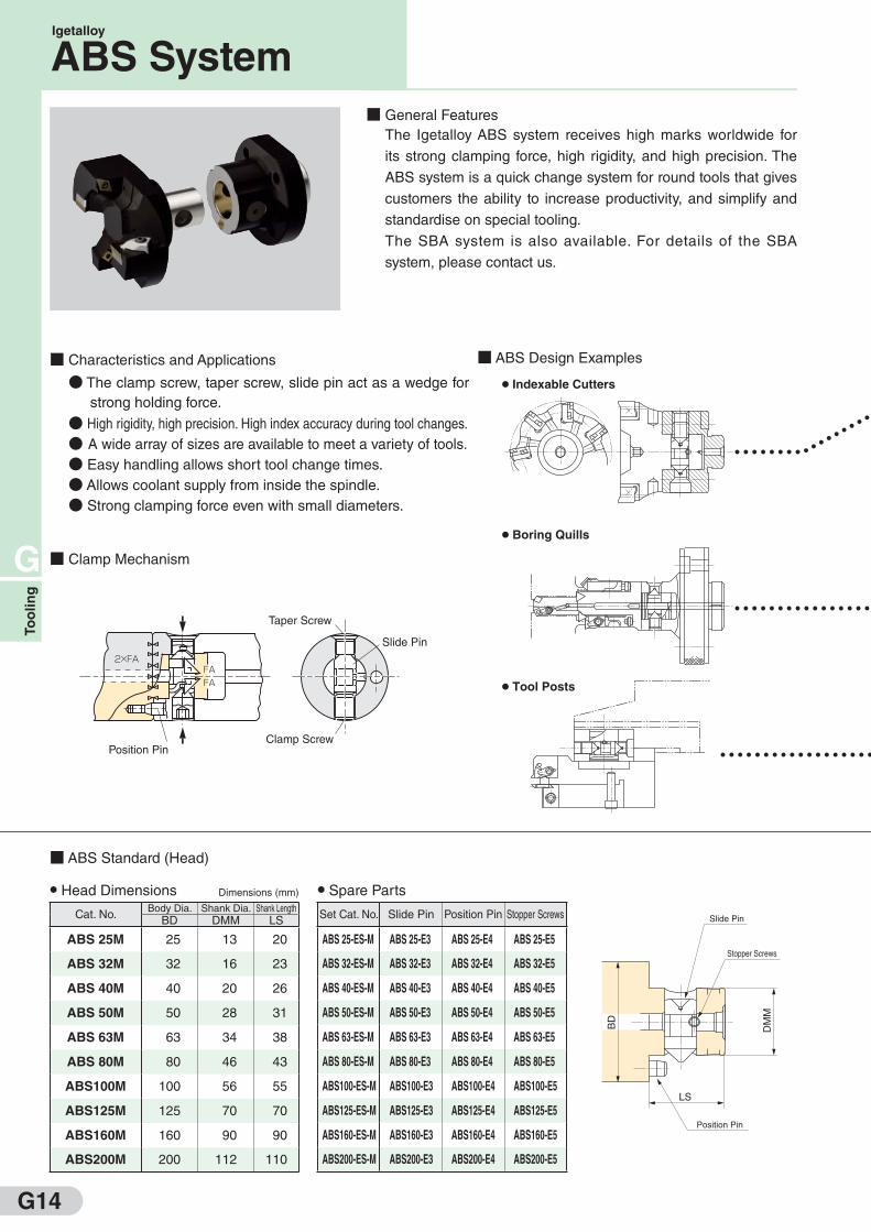
■ General Features
The Igetalloy ABS system receives high marks worldwide for
its strong clamping force, high rigidity, and high precision. The
ABS system is a quick change system for round tools that gives
customers the ability to increase productivity, and simplify and
standardise on special tooling.
The SBA system is also available. For details of the SBA
system, please contact us.
■ Characteristics and Applications
● The clamp screw, taper screw, slide pin act as a wedge for
strong holding force.
● High rigidity, high precision. High index accuracy during tool changes.
● A wide array of sizes are available to meet a variety of tools.
● Easy handling allows short tool change times.
● Allows coolant supply from inside the spindle.
● Strong clamping force even with small diameters.
■ ABS Design Examples
■ Clamp Mechanism
■ ABS Standard (Head)
● Head Dimensions
Cat. No.Body Dia. Shank Dia. Shank Length
BD DMM LS
ABS 25M 25 13 20
ABS 32M 32 16 23
ABS 40M 40 20 26
ABS 50M 50 28 31
ABS 63M 63 34 38
ABS 80M 80 46 43
ABS100M 100 56 55
ABS125M 125 70 70
ABS160M 160 90 90
ABS200M 200 112 110
● Spare Parts
Set Cat. No. Slide Pin Position Pin Stopper Screws
ABS 25-ES-M ABS 25-E3 ABS 25-E4 ABS 25-E5
ABS 32-ES-M ABS 32-E3 ABS 32-E4 ABS 32-E5
ABS 40-ES-M ABS 40-E3 ABS 40-E4 ABS 40-E5
ABS 50-ES-M ABS 50-E3 ABS 50-E4 ABS 50-E5
ABS 63-ES-M ABS 63-E3 ABS 63-E4 ABS 63-E5
ABS 80-ES-M ABS 80-E3 ABS 80-E4 ABS 80-E5
ABS100-ES-M ABS100-E3 ABS100-E4 ABS100-E5
ABS125-ES-M ABS125-E3 ABS125-E4 ABS125-E5
ABS160-ES-M ABS160-E3 ABS160-E4 ABS160-E5
ABS200-ES-M ABS200-E3 ABS200-E4 ABS200-E5
LS
DM
M
BD
Slide Pin
Stopper Screws
Position Pin
Taper Screw
Slide Pin
Clamp ScrewPosition Pin
2×FAFAFA
Igetalloy
ABS System
Dimensions (mm)
G15
G
To
olin
g
Adaptor
Head
For indexable cutters…
For boring quills
…
For drills
…
For tool posts…
Slide Pin
Position Pin
Clamp Screw
Taper Screw
Stopper Screw
● Adaptor Dimensions
Cat. No.Body Dia. Bore dia. Bore Depth Clamping Length
BD DCB CBDP LB
ABS 25W 25 13 22 13.0
ABS 32W 32 16 25 16.0
ABS 40W 40 20 30 18.5
ABS 50W 50 28 34 22.0
ABS 63W 63 34 41 28.0
ABS 80W 80 46 48 34.0
ABS100W 100 56 58 40.5
ABS125W 125 70 76 51.0
ABS160W 160 90 96 53.0
ABS200W 200 112 116 82.0
● Spare Parts
Set Cat. No. Clamp Screw Taper Screw
ABS 25-FS-W ABS 25-F1 ABS 25-F2
ABS 32-FS-W ABS 32-F1 ABS 32-F2
ABS 40-FS-W ABS 40-F1 ABS 40-F2
ABS 50-FS-W ABS 50-F1 ABS 50-F2
ABS 63-FS-W ABS 63-F1 ABS 63-F2
ABS 80-FS-W ABS 80-F1 ABS 80-F2
ABS100-FS-W ABS100-F1 ABS100-F2
ABS125-FS-W ABS125-F1 ABS125-F2
ABS160-FS-W ABS160-F1 ABS160-F2
ABS200-FS-W ABS200-F1 ABS200-F2
■ ABS Standard (Adaptor)
CBDP
LB(Min.)
Clamp Screw
Taper Screw
BD
DC
B
Igetalloy
ABS System
Dimensions (mm)

G16
G
Un
it
Note: Please recommend using MUP type micro units when designing
new tooling. MUN type should only be used as replacement parts for
existing tooling which are already using these micro units.
■ Typical Toolings
MUP Type MUN Type
Illustrations Applications Cat. No.Min.
Bore Dia.(mm)
Stock Cat. No.Min.
Bore Dia.(mm)
Stock
MUP1-A0 25 D MUN2 -A0 36
MUP2-A0 36 D MUN3 -A0 47
MUP3-A0 47 D MUN3L-A0 54
MUP4-A0 73 MUN4 -A0 73
MUN4L-A0 78
MUP1-A15 25 MUN2 -A15 36
MUP2-A15 36 MUN3 -A15 47
MUP3-A15 47 MUN3L-A15 54
MUP4-A15 73 MUN4 -A15 73
MUN4L-A15 78
MUP1-V0 25 D MUN2 -V0 36
MUP2-V0 36 D MUN3 -V0 47
MUP3-V0 47 D MUN3L-V0 54
MUP4-V0 73 MUN4 -V0 73
MUN4L-V0 78
MUP1-V15 25 MUN2 -V15 36
MUP2-V15 36 MUN3 -V15 47
MUP3-V15 47 MUN3L-V15 54
MUP4-V15 73 MUN4 -V15 73
MUN4L-V15 78
* If a left-hand unit is required, include "LH" after the catalog number (ex. MUP1-A0-LH, MUP1-V0-LH)
* Micro Units do not include inserts or spanners.
SEC-
Micro Units

G17
G
Un
it
■ Features
Classification Standard Type MINIT Type ISO Type
Type
Shape
Functions
BU Type MINIT P24 Type MINIT N38 Type SP Type CP Type CE Type PN Type
The most common type of cartridge units
Mini type with good edge sharpness and chip control
Compact type for multi-tooling configurations
Screw-locked positive edge type with good edge sharpness and chip control
Positive edge type for low rigidity work
High rake type for Non-ferrous metal machining
Economical type using common negative inserts
Clamp Mechanism Eccentric Pin Screw On Pin Lock Screw On Clamp On Clamp On Pin Lock
Adjustability YesAxial: No
Radial: Yes
No
(By using shims)Yes Yes Yes Yes
Rake Angle Neg. Pos. Neg. Pos. Pos. Pos. Neg.
Relief Angle 0° 11° 0° 11° 11° 20° 0°
Cutting Edge Position Above Center Above Center Above Center On Center On Center On Center On Center
Min. Effective Diameter (mm) ø24 ø24 ø38 ø30 ø30 ø30 ø38
■ Typical Toolings (For Triangular Inserts) ( ) Indicate Smallest Applicable Diameter.
Illustrations BU TypeStock
MINIT P24 TypeStock
MINIT N38 TypeStock
SP TypeStock
CP TypeStock
CE TypeStock
PN TypeStock
R L R L R L R L R L R L R L
MTGN3 R/L(38) D D STGP R/L-10CA(38) D D CTGP R/L10CA(38) D D CTGE R/L10CA(38) PTGN R/L10CA(38) D D
STGP R/L-12CA(50) D D CTGP R/L12CA(50) D D CTGE R/L12CA(50) PTGN R/L12CA(50) D D
STGP R/L-16CA(60) D D CTGP R/L16CA(60) D D PTGN R/L16CA(60) D D
PTGN R/L20CA(70) F D
< > : MINIT P24
BU224 R/L(48) D MTJP22 R/L(24) D D MTJN3 R/L(38) D STJP R/L-10CA(38) D D CTJP R/L10CA(38) D CTJE R/L10CA(38) D
BU225 R/L(60) D STJP R/L-12CA(50) D D CTJP R/L12CA(50) D CTJE R/L12CA(50) D
STJP R/L-16CA(55) D D CTJP R/L16CA(55)
BU252 R/L(24) D D MTFP22 R/L(24) D D MTFN3 R/L(38) D D STFP R/L- 8CA(30) D D CTFP R/L 8CA(30) D D CTFE R/L 8CA(30) D D PTFN R/L10CA(38) D D
BU253 R/L(30) D STFP R/L-10CA(38) D D CTFP R/L10CA(38) D D CTFE R/L10CA(38) D D PTFN R/L12CA(50) D D
BU254 R/L(38) D STFP R/L-12CA(50) D D CTFP R/L12CA(50) D D CTFE R/L12CA(50) D D PTFN R/L16CA(55) D D
BU255 R/L(48) D D STFP R/L-16CA(55) D D CTFP R/L16CA(55) D D CTFE R/L16CA(55) D F PTFN R/L20CA(70) D D
BU256 R/L(55) D CTFP R/L20CA(70) D D CTFE R/L20CA(70) D
< > : MINIT P24·N38
BU293 R/L(30) D MTUP22 R/L(24) D D MTUN3 R/L(38) D D STUP R/L-10CA(38) D D CTUP R/L10CA(38) D D CTUE R/L10CA(38) D
BU294 R/L(38) D STUP R/L-12CA(50) D D CTUP R/L12CA(50) D CTUE R/L12CA(50) F
BU295 R/L(48) D D STUP R/L-16CA(55) D D CTUP R/L16CA(55) D
BU295ER/L(48) D
STTP R/L- 8CA(30) D D CTTP R/L 8CA(30) D CTTE R/L 8CA(30) D PTTN R/L10CA(38) D F
STTP R/L-10CA(38) D D CTTP R/L10CA(38) D D CTTE R/L10CA(38) D PTTN R/L12CA(50) D D
STTP R/L-12CA(50) D D CTTP R/L12CA(50) D D CTTE R/L12CA(50) D PTTN R/L16CA(60) D F
STTP R/L-16CA(60) D D CTTP R/L16CA(60) D F CTTE R/L16CA(60) F
STSP R/L-10CA(38) D D CTSP R/L10CA(38) D CTSE R/L 8CA(30) D
STSP R/L-12CA(50) D D CTSP R/L12CA(50) D CTSE R/L10CA(38) D
STSP R/L-16CA(55) D D CTSP R/L16CA(55) D CTSE R/L12CA(50) D
CTSE R/L16CA(55) F
MTWP22 R/L(24) D D MTWN3 R/L(38) D STWP R/L- 8CA(30) D D CTWP R/L 8CA(30) D CTWE R/L 8CA(30) D
STWP R/L-10CA(38) D D CTWP R/L10CA(38) D D CTWE R/L10CA(38) D
STWP R/L-12CA(50) D D CTWP R/L12CA(50) D D CTWE R/L12CA(50) D
STWP R/L-16CA(55) D D CTWP R/L16CA(55) F CTWE R/L16CA(55)
* Cartridge Units do not include inserts or toolholders.
5°
0°
0°
5° <3°>
45°
30°
5° <3°>
60°
F mark : To be replaced by new item (Please confirm stock availability)
SEC-
Cartridge Units
F mark : To be replaced by new item (Please confirm stock availability)G18
G
Un
it
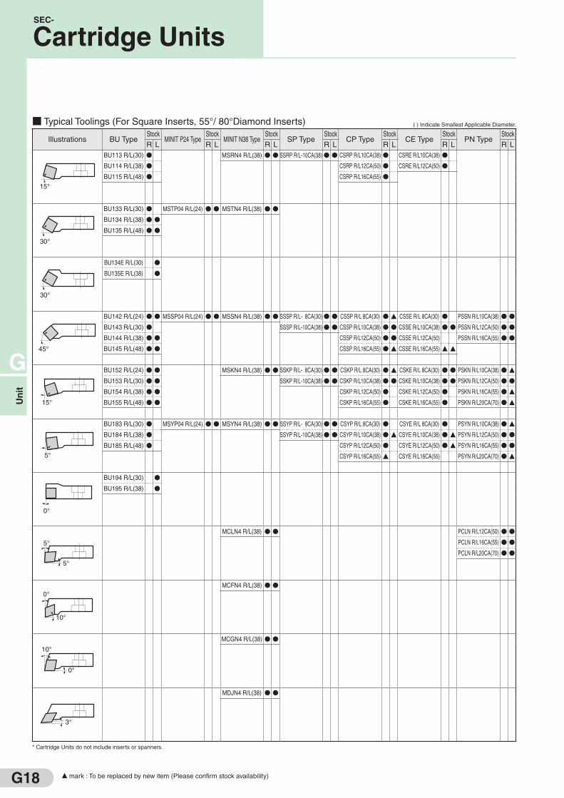
■ Typical Toolings (For Square Inserts, 55°/ 80°Diamond Inserts) ( ) Indicate Smallest Applicable Diameter.
Illustrations BU TypeStock
MINIT P24 TypeStock
MINIT N38 TypeStock
SP TypeStock
CP TypeStock
CE TypeStock
PN TypeStock
R L R L R L R L R L R L R L
BU113 R/L(30) D MSRN4 R/L(38) D D SSRP R/L-10CA(38)D D CSRP R/L10CA(38) D CSRE R/L10CA(38) DBU114 R/L(38) D CSRP R/L12CA(50) D CSRE R/L12CA(50) D
BU115 R/L(48) D CSRP R/L16CA(55) D
BU133 R/L(30) D MSTP04 R/L(24) D D MSTN4 R/L(38) D D
BU134 R/L(38) D D
BU135 R/L(48) D D
BU134E R/L(30) D
BU135E R/L(38) D
BU142 R/L(24) D D MSSP04 R/L(24) D D MSSN4 R/L(38) D D SSSP R/L- 8CA(30)D D CSSP R/L 8CA(30) D F CSSE R/L 8CA(30) D PSSN R/L10CA(38) D D
BU143 R/L(30) D SSSP R/L-10CA(38)D D CSSP R/L10CA(38) D D CSSE R/L10CA(38) D D PSSN R/L12CA(50) D D
BU144 R/L(38) D D CSSP R/L12CA(50) D D CSSE R/L12CA(50) PSSN R/L16CA(55) D D
BU145 R/L(48) D D CSSP R/L16CA(55) D F CSSE R/L16CA(55) F F
BU152 R/L(24) D D MSKN4 R/L(38) D D SSKP R/L- 8CA(30)D D CSKP R/L 8CA(30) D F CSKE R/L 8CA(30) D D PSKN R/L10CA(38) D F
BU153 R/L(30) D D SSKP R/L-10CA(38)D D CSKP R/L10CA(38) D D CSKE R/L10CA(38) D D PSKN R/L12CA(50) D D
BU154 R/L(38) D D CSKP R/L12CA(50) D CSKE R/L12CA(50) D PSKN R/L16CA(55) D F
BU155 R/L(48) D D CSKP R/L16CA(55) D CSKE R/L16CA(55) D PSKN R/L20CA(70) D F
BU183 R/L(30) D MSYP04 R/L(24) D D MSYN4 R/L(38) D D SSYP R/L- 8CA(30)D D CSYP R/L 8CA(30) D CSYE R/L 8CA(30) D PSYN R/L10CA(38) D F
BU184 R/L(38) D SSYP R/L-10CA(38)D D CSYP R/L10CA(38) D F CSYE R/L10CA(38) D F PSYN R/L12CA(50) D D
BU185 R/L(48) D CSYP R/L12CA(50) D CSYE R/L12CA(50) D F PSYN R/L16CA(55) D D
CSYP R/L16CA(55) F CSYE R/L16CA(55) PSYN R/L20CA(70) D F
BU194 R/L(30) D
BU195 R/L(38) D
MCLN4 R/L(38) D D PCLN R/L12CA(50) D D
PCLN R/L16CA(55) D D
PCLN R/L20CA(70) D D
MCFN4 R/L(38) D D
MCGN4 R/L(38) D D
MDJN4 R/L(38) D D
* Cartridge Units do not include inserts or spanners.
30°
0°
0°
10°
10°
0°
5°
5°
3°
15°
15°
45°
30°
5°
SEC-
Cartridge Units
G19
G
Un
it
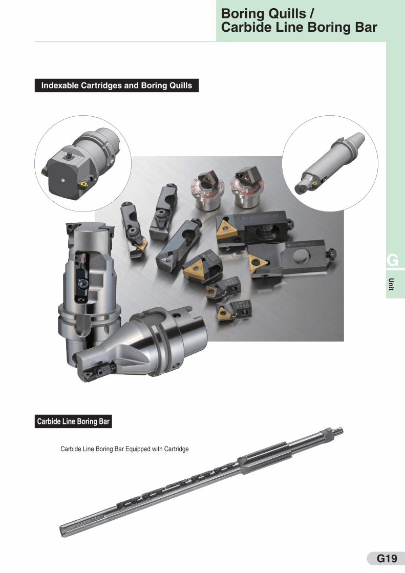
Indexable Cartridges and Boring Quills
Carbide Line Boring Bar
Boring Quills /Carbide Line Boring Bar
Carbide Line Boring Bar Equipped with Cartridge

G20