transmitter quick start guide - handa- · pdf filetransmitter control unit antenna key ring...
TRANSCRIPT

Publications No.
INSTALLATIONINSTRUCTIONS
Accessory Application
© 2008 American Honda Motor Co., Inc. – All Rights Re
AII 35843-38915
REMOTE CONTROL ENGINE STARTERserved AII 35843-38915 (0
2008 CR-V
802) 0
Issue Date
FEB 2008
PARTS LIST
Remote Engine Starter KitP/N 08E91-E22-100B
Transmitter
Control unit
Antenna
Key ring
Protective tape
Fuse label
Caution label
Accessory User’s Information Manual
Quick Start Guide
Remote Control Engine Starter Attachment ()P/N 08E92-SWA-100
Engine starter harness
Control unit bracket
Template
1 of 278E92-SWA-1000-91
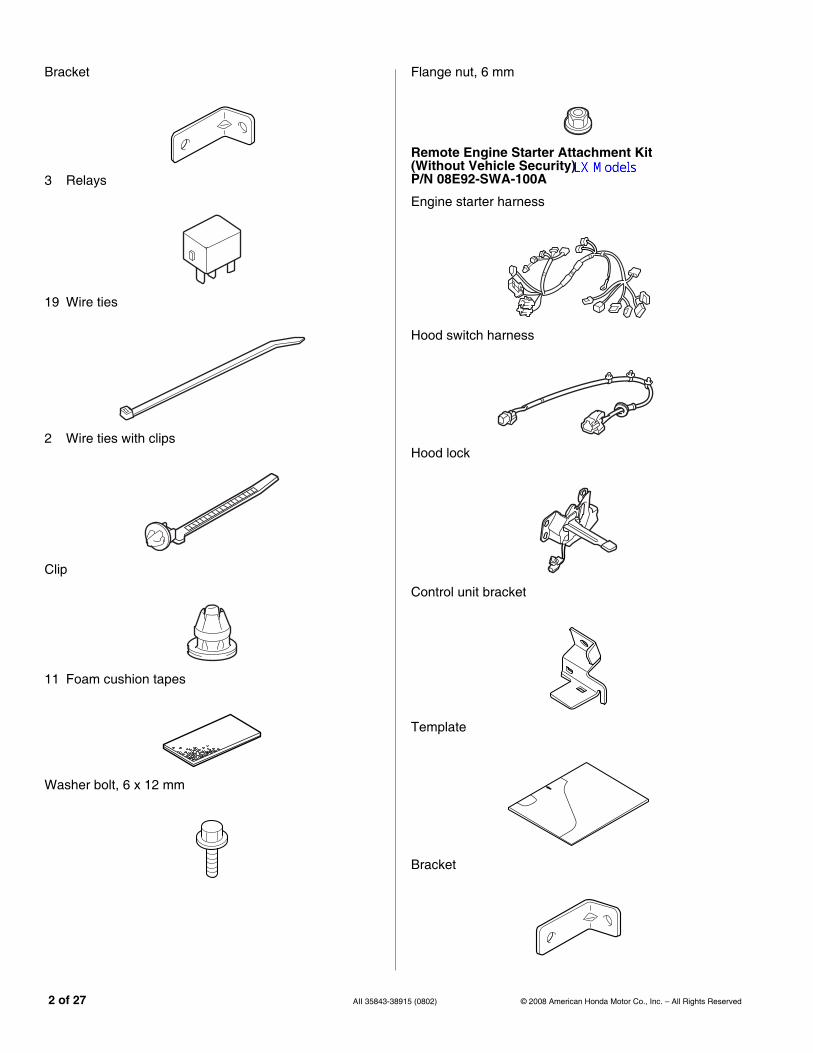
Bracket
3 Relays
19 Wire ties
2 Wire ties with clips
Clip
11 Foam cushion tapes
Washer bolt, 6 x 12 mm
2 of 27 AII 35843-389
Flange nut, 6 mm
Remote Engine Starter Attachment Kit (Without Vehicle Security)P/N 08E92-SWA-100A
Engine starter harness
Hood switch harness
Hood lock
Control unit bracket
Template
Bracket
15 (0802) © 2008 American Honda Motor Co., Inc. – All Rights Reserved

3 Relays
25 Wire ties
2 Wire ties with clips
Clip A
Clip B
11 Foam cushion tapes
Washer bolt, 6 x 12 mm
© 2008 American Honda Motor Co., Inc. – All Rights Reserved AII 35843-38
Flange nut, 6 mm
2 Spacers
TOOLS AND SUPPLIES REQUIRED
#2 Phillips screwdriver
Flat-tip screwdriver
Diagonal cutters
Ratchet
8 mm Socket
10 mm Socket
12 mm Deep socket
10 mm Combination wrenches
10 mm Wrench
Hook tool
Felt-tip pen
Isopropyl alcohol
Electrical tape
Scissors
Small flat-tip screwdriver
T25 Torx bit
Shop towel
Scale
Rubber mallet
HDS (Honda Diagnostic System)
Torque wrench
Fender cover
Masking tape
Needle nose pliers
915 (0802) 3 of 27

Illustration of the Engine Starter Installed on the VehicleWith Vehicle Security
Without Vehicle Security
6D0404AK
FUSE CASE (30 A, 40 A)
ANTENNA ENGINE STARTER HARNESS
CONTROL UNIT
FUSE(3 A, 3 A)
6D0405AK
FUSE CASE (30 A, 40 A)
ANTENNAENGINE STARTER HARNESS
CONTROL UNITHOOD SWITCH HARNESS
HOOD LOCK
FUSE(3 A, 3 A)
4 of 27 AII 35843-389
INSTALLATION
NOTE: This antenna should only be installed if the ambient air temperature 15°C (60°F) or above.
1. Make sure you have the anti-theft code for the radio, then write down the frequencies for the preset buttons.
2. Disconnect the negative cable from the battery.
Customer Information: The information in thisinstallation instruction is intended for use only by skilledtechnicians who have the proper tools, equipment, andtraining to correctly and safely add equipment to yourvehicle. These procedures should not be attempted by“do-it-yourselfers.”
15 (0802) © 2008 American Honda Motor Co., Inc. – All Rights Reserved

Setting the Control Unit
3. Get the control unit. Using a small flat-tip screwdriver, adjust the switches on the (accessory) control unit to the locations shown. Using isopropyl alcohol on a shop towel, clean the area where the protective tape will attach. Remove the adhesive backing, and attach the protective tape to the control unit.
NOTE:
• The switches must be selected before the control unit is plugged in.
• If the switch setting is not correct, the enginestarter will not operate properly.
• If setting the switches with the control unit installed in the vehicle, touch a metal part of the screwdriver to any metal part of the vehicle to discharge any static electricity.
• If you change the switch settings with the unit connected, you must disconnect the unit then reconnect it before the settings change.
CONTROL UNIT
SMALLFLAT-TIP SCREW-DRIVER
Discharge any static electricity.
The switches mustbe selected before the control unit is plugged in.
SET
SWITCHES
SW:1 RR Junction unit -----------------------> OFF
SW:2 Trunk or Tailgate ----------------------> ON
SW:3 Smart Entry -----------------------------> OFF
SW:4 Horn or Buzzer Answerback ------> OFF
SW:5 Trunk Main SW -------------------------> OFF
SW:6 Reserve ----------------------------------> OFF
SWITCHES
© 2008 American Honda Motor Co., Inc. – All Rights Reserved AII 35843-38
SW:1 RR Junction Unit
SW:2 Trunk or Tailgate
SW:3 Smart Entry
SW:4 Horn or Buzzer Answer Back
SW:5 Trunk Main SW
SW:6 Reserve
4. Turn the knob of the driver’s seat side under cover. Remove the driver’s seat side under cover (a pin and a clip).
5. Remove the driver’s side lower dash cover (seven clips and two hooks). Take care not to damage the clips and hooks.
6303080B
DRIVER’S SEAT SIDE UNDER COVER
KNOB(Turn.)
CLIP
PIN
6303071B DRIVER’S SIDE LOWER DASH COVER
7 CLIPS
HOOKS
915 (0802) 5 of 27

6. Remove the left front side step trim (three clips).
7. Pull out the front door opening seal and remove the driver’s seat side kick panel (two clips).
6303090B
3 CLIPS
LEFT FRONT SIDE STEP TRIM
6303100B
2 CLIPS
FRONT DOOR OPENING SEAL(Pull out.)
DRIVER’S SEAT SIDE KICK PANEL
6 of 27 AII 35843-389
8. Lower the tilt lever and pull steering wheel outward. Insert a flat-tip screwdriver into the guide on the under side of the steering column lower cover and release the retaining tab.
9. Remove the steering column upper cover (four retaining tabs).
10. Remove the steering column lower cover (two self-tapping screws and one screw).
7215010K
Push.
FLAT-TIPSCREWDRIVER
STEERING COLUMN UPPER COVER
RETAINING TAB
STEERING COLUMN LOWER COVER
GUIDE
TILT LEVER
6819030Y
SELF-TAPPING SCREWS
SCREW
STEERING COLUMN LOWER COVER
15 (0802) © 2008 American Honda Motor Co., Inc. – All Rights Reserved

11. Remove the map light lenses (two retaining tabs each).
12. Remove the map light (four bolts and disconnect the vehicle connectors).
6522020Y
LENS
LENS2 RETAINING TABS
2 RETAINING TABS
MAP LIGHT
6313021Y
MAP LIGHT
VEHICLE CONNECTOR
4 BOLTS
© 2008 American Honda Motor Co., Inc. – All Rights Reserved AII 35843-38
13. Using a flat-tip screwdriver, remove the right and left sunvisor holders.
14. Pull away the weatherstrip from the left front A-pillar trim.
6308170Y
RIGHT SUNVISOR HOLDER
Push.
LEFT SUNVISOR HOLDER
FLAT-TIP SCREWDRIVER
Turn.
7212011S
Strike perpendicularly to the vehicle.
CLIPPIN
PIN
TRIANGLE MARK
RUBBER MALLET
LEFT FRONT A-PILLAR TRIM
CLIP
STRIKE POINT
SHOP TOWEL
DOOR OPENING SEAL
LEFT FRONT A-PILLAR TRIMLEFT FRONT
A-PILLAR
915 (0802) 7 of 27

15. Using a small rubber mallet and a shop towel, gently tap the left front A-pillar trim at the position shown to release the clip.
16. Pull away the weatherstrip from the left front A-pillar trim. Remove the left front A-pillar trim (two clips).
17. Remove and discard the clip from the left front A-pillar, and install a new A-pillar (supplied) clip on the left front A-pillar trim.
6227020H
DOOR OPENING SEAL
LEFT FRONT A-PILLAR TRIM
3 CLIPS
720903AK
LEFT FRONT A-PILLAR TRIM
LEFT FRONT A-PILLAR
CLIP(Discard.)
NEW CLIP
8 of 27 AII 35843-389
Installing the Antenna
18. Using two pairs of needle nose pliers, bend the antenna plate according to the dimensions shown.
6N3001CK
SCALE
ANTENNAANTENNA PLATE
24 mm (0.9 in.)
NEEDLE NOSE PLIERS
PLATE
24 mm (0.9 in.)
15 (0802) © 2008 American Honda Motor Co., Inc. – All Rights Reserved

19. Using scissors, cut out the template.
20. Using tape, secure the template to the windshield by aligning it with the edge of the black ceramic paint.
Cut out.
TEMPLATE
6N3002AK
REARVIEW MIRROR
BLACK CERAMIC PAINT
EDGE OF BLACK CERAMIC PAINT
Align these ends with the ends of the black ceramic paint.
TAPETEMPLATE
WINDSHIELD
© 2008 American Honda Motor Co., Inc. – All Rights Reserved AII 35843-38
21. Starting near the end of the antenna cable, wrap three foam cushion tapes and three half foam cushion tapes around the antenna cable at the measurements shown.
22. Using scissors, cut one foam cushion tape to the measurement shown. Attach the cut piece of foam cushion tape to the antenna plate as shown.
6N3003AK
FOAM CUSHION TAPE
ANTENNA
720 mm (28 in.)
ANTENNA CABLE
390 mm (15 in.)
30 mm (1.2 in.)
FOAM CUSHION TAPE
Cut.
HALF FOAM CUSHION TAPE
30 mm (1.2 in.)
30 mm (1.2 in.)
30 mm (1.2 in.)
780101BK
ANTENNA
FOAM CUSHION TAPE
15 mm(0.6 in.)
Cut.
60 mm(2.4 in.)
ANTENNA PLATE
Align.
915 (0802) 9 of 27

23. Using isopropyl alcohol on a shop towel, clean the area where the antenna will attach. Allow the alcohol to dry before proceeding.
24. Remove the adhesive backing from the antenna, insert the antenna plate under the roof lining, and attach the antenna to the windshield aligning the template.
25. Remove the template.
26. Push the antenna cable into the roof lining as shown. Be careful not to crease the roof lining.
6N3004BK
TEMPLATE
ADHESIVE BACKING
ANTENNA
ANTENNA PLATE
6N30050K
ANTENNA CABLE
ROOF LINING
10 of 27 AII 35843-389
27. Clean the vehicle panel surface where the foam cushion tape will attach using isopropyl alcohol. Secure the antenna cable to the vehicle panel with the remaining piece of foam cushion tape you cut in step 21. Be careful not to crease the roof lining.
28. Clean the vehicle panel surface where the foam cushion tape will attach using isopropyl alcohol. Secure the antenna cable to the vehicle panel using one foam cushion tape. Be careful not to crease the roof lining.
6N3006BK
FOAM CUSHION TAPE(From step 22.)
VEHICLE PANEL
FOAM CUSHION TAPE
ANTENNA CABLE
ANTENNA
FOAM CUSHION TAPE
ANTENNA CABLE
6N30070K
ANTENNA CABLE
ANTENNA
FOAM CUSHION TAPE
VEHICLE PANEL
15 (0802) © 2008 American Honda Motor Co., Inc. – All Rights Reserved

29. Route the antenna cable along the left front A-pillar and secure it to the vehicle harness with the five wire ties as shown.
30. Pull away the door opening seal. Route the antenna cable down under the dashboard. Tuck the antenna cable between the left front pillar and the dashboard, and reinstall the door opening seal.
720905AK
LEFT FRONT PILLAR
ANTENNA CABLE
5 WIRE TIES
VEHICLE HARNESS
VEHICLE CLIP
751650AK
LEFT FRONT PILLAR
ANTENNA CABLE
DASHBOARD
DOOR OPENING SEAL
© 2008 American Honda Motor Co., Inc. – All Rights Reserved AII 35843-38
Routing the Engine Starter Harness
31. Route the engine starter harness under the dashboard area as shown.
32. Attach the 30 A, 40 A, and 3 A fuse labels to the relay block and the fuse case of the engine starter harness.
33. Install the three relays to the relay block of the engine starter harness.
721307BK
ENGINE STARTER HARNESS
6N3008BK
RELAY
3 A FUSE LABEL
ENGINE STARTER HARNESS RELAY BLOCK
30 A FUSE LABEL
40 A FUSE LABEL
915 (0802) 11 of 27

34. Unlock the vehicle 42-pin connector by pushing the retaining tab on the connector, and disconnect the connector from the fuse box.
35. Disconnect the vehicle 4-pin connector, and the 2-pin connector from the top of the fuse box.
36. Wrap one foam cushion tape around the vehicle 4-pin connector and one around the 2-pin connector.
37. Secure the vehicle 4-pin connector and 2-pin connector to the vehicle harness using one wire tie.
751701AK
VEHICLE2-PINCONNECTOR
VEHICLE42-PINCONNECTOR
FUSE BOXRETAINING TAB
Push.
VEHICLE 4-PIN CONNECTOR
VEHICLE 2-PINCONNECTOR
VEHICLE 4-PIN CONNECTOR
751702AK
WIRE TIE
VEHICLE HARNESSFOAM CUSHION TAPE
VEHICLE4-PIN AND 2-PIN CONNECTOR
12 of 27 AII 35843-389
38. Plug the engine starter harness 4-pin and 2-pin connectors into the fuse box.
Check that the engine starter harness 4-pin and 2-pin connectors are connected to the fuse box and they are locked securely. A loose connector can cause a engine to stall.
39. Reconnect the vehicle 42-pin connector to the fuse box.
40. Route the antenna cable as shown.
752101BK
VEHICLE42-PINCONNECTOR
ENGINE STARTER HARNESS2-PINCONNECTOR
ENGINE STARTER HARNESS4-PIN CONNECTOR
Pull on the connector to verify it’s locked properly.
FRONT VIEW
752102AK
ANTENNA CABLE
ENGINE STARTER HARNESS GROUND TERMINAL
GROUND BOLT(Reuse.)
15 (0802) © 2008 American Honda Motor Co., Inc. – All Rights Reserved

41. Remove the ground bolt from the vehicle. Secure the engine starter harness ground terminal using the ground bolt you just removed.
42. Disconnect the vehicle 20-pin connectors from the right side of the fuse box, and plug them into the engine starter harness 20-pin connectors.
43. Disconnect the vehicle 23-pin connectors from under the fuse box, and plug them into the engine starter harness 23-pin connectors (white).
752103AK ENGINE STARTER HARNESS 20-PIN CONNECTORS
VEHICLE 20-PIN CONNECTORS
FUSE BOX
VEHICLE20-PINCONNECTOR
ENGINE STARTER HARNESS 20-PIN CONNECTOR
752104BK
VEHICLE 23-PIN CONNECTORS
ENGINE STARTER HARNESS 23-PIN CONNECTORS (WHITE)
FUSE BOX
VEHICLE23-PINCONNECTOR
© 2008 American Honda Motor Co., Inc. – All Rights Reserved AII 35843-38
44. Disconnect the vehicle 24-pin connectors from under the fuse box, and plug them into the engine starter harness 24-pin connectors.
45. Attach the engine starter harness 24-pin connector to the vehicle 24-pin connector.
46. If the vehicle is equipped with the factory security system, secure the engine starter harness 2-pin connector (white) to the vehicle harness, it will not be used. If the vehicle is not equipped with the security system, the connector will be used in a later step.
47. Secure the engine starter harness 23-pin connector (blue), and the engine starter harness to the engine starter harness and vehicle harness using three wire ties.
752105BK
VEHICLE 24-PIN CONNECTOR
ENGINE STARTER HARNESS 24-PIN CONNECTOR
VEHICLE 24-PIN CONNECTOR
FUSE BOX
ENGINE STARTER HARNESS 24-PIN CONNECTORS
752106BK
ENGINE STARTER HARNESS23-PINCONNECTOR(Blue)
ENGINE STARTER HARNESS
5 WIRE TIES
VEHICLE HARNESS
WIRE TIE (if vehicle is equipped with factory security system)
ANTENNA CABLE
915 (0802) 13 of 27

48. Attach the wire tie with clip to the engine starter harness and the antenna cable at the green tape then push the clip into the hole in the steering hanger beam.
49. Install the bracket to the instrument panel using one 6 x 12 mm washer bolt, and one 6 mm flange nut.
721203AK
ENGINE STARTER HARNESS
WIRE TIE WITH CLIPSTEERING HANGER BEAM
ANTENNA CABLE
GREEN TAPE
6310061Y
INSTRUMENT PANEL
6 x 12 mm WASHER BOLT
BRACKET6 mm FLANGE NUT
14 of 27 AII 35843-389
50. Attach the wire tie with clip to the engine starter harness and the antenna cable at the other green tape, then push the clip into the hole in the bracket.
51. Route the engine starter harness 7-pin connectors (brown, green, white) towards the steering column.
7212040K
BRACKET
ENGINE STARTER HARNESS
ENGINE STARTER HARNESS
WIRE TIE WITH CLIP
ANTENNA CABLE
ANTENNA CABLE
GREEN TAPE
6D01120Y
ENGINE STARTER HARNESS
ENGINE STARTER HARNESS 7-PIN CONNECTOR
STEERING COLUMN
ENGINE STARTER HARNESS 7-PIN CONNECTOR
VEHICLE HARNESS
15 (0802) © 2008 American Honda Motor Co., Inc. – All Rights Reserved

52. Disconnect the vehicle 7-pin connector (brown) from the ignition switch and connect the engine starter harness 7-pin connector (brown) as shown.
Check that the engine starter harness 7-pin connector (brown) is connected to the vehicle connector and it is locked securely. A loose connector can cause engine stall.
53. Wind one foam cushion around the vehicle 7-pin connector (brown).
54. Disconnect the vehicle 7-pin connector (white) from the ignition switch, and plug in the engine starter harness 7-pin connector (white) as shown.
721301AK
VEHICLE 7-PINCONNECTOR (brown)
ENGINE STARTER HARNESS
ENGINE STARTER HARNESS 7-PIN CONNECTOR (brown)
IGNITION SWITCH
FOAM CUSHION TAPE
Pull on the connector to verify that it’s locked properly.
7213020K
ENGINE STARTER HARNESS 7-PIN CONNECTOR (white)
VEHICLE 7-PIN CONNECTOR (white)
IGNITION SWITCH
ENGINE STARTER HARNESS
© 2008 American Honda Motor Co., Inc. – All Rights Reserved AII 35843-38
55. Insert the vehicle 7-pin connector (brown) into the gap on the steering column.
56. Secure the engine starter harness to the vehicle harness using two wire ties.
57. Disconnect the vehicle 8-pin connector (black) from the wiper switch, and plug the engine starter harness 8-pin connector to the wiper switch.
7212050K
VEHICLE 7-PIN CONNECTOR (brown)
ENGINE STARTER HARNESS
WIRE TIE
VEHICLE PANEL
GREEN TAPE
6D01160Y
ENGINE STARTER HARNESS 8-PIN CONNECTOR
VEHICLE 8-PINCONNECTOR (black)
WIPER SWITCH
915 (0802) 15 of 27

58. Plug the vehicle 8-pin connector (black) to the engine starter harness 8-pin connector.
59. Secure the engine starter 8-pin connector (black) to the vehicle harness using one wire tie.
60. Attach the engine starter harness to the fuse case of the vehicle relay block.
6D01171Y
VEHICLE 8-PIN CONNECTOR (black)
ENGINE STARTER 8-PIN CONNECTOR (b lack)
WIRE TIE
7213030K
ENGINE STARTER HARNESS
ENGINE STARTER HARNESS FUSE CASE
VEHICLE RELAY BLOCK
STEERING SHAFT
16 of 27 AII 35843-389
61. Align the green tape on the engine starter harness with the vehicle harness clip, and secure the engine starter harness to the vehicle harness with one wire tie.
62. Secure the engine starter harness relay block to the vehicle frame.
63. Remove the vehicle nut. Secure the control unit bracket to the vehicle frame using the vehicle nut you just removed.
721304AK
ENGINE STARTER HARNESS
ENGINE STARTER HARNESS RELAY BLOCK
VEHICLE FRAME
VEHICLE HARNESS
WIRE TIE
VEHICLE CLIP
GREEN TAPE
6N3009AK
VEHICLE FRAMEVEHICLE
NUT(Reuse.)
CONTROL UNIT BRACKET
15 (0802) © 2008 American Honda Motor Co., Inc. – All Rights Reserved

64. Connect the antenna cable terminal to the control unit as shown.
65. Plug the engine starter harness 28-pin connector into the control unit.
66. Slide the control unit onto the control unit bracket.
6D0402BK
CONTROL UNIT
ENGINE STARTER HARNESS28-PINCONNECTORANTENNA CABLE TERMINAL
(Connect first.)
6D0401AK
CONTROL UNIT BRACKET
CONTROL UNIT
© 2008 American Honda Motor Co., Inc. – All Rights Reserved AII 35843-38
67. Secure the engine starter harness and antenna cable to the engine starter harness using two wire ties.
68. Bundle the excess antenna cable, and secure it to the engine starter harness using two wire ties.
69. Clean the steering column lower cover on the bracket surface where the urethane foam will attach using isopropyl alcohol. Attach the urethane foam to the bracket.
6D0403AK
CONTROL UNIT
WIRE TIES
ANTENNA CABLE (Bundle the excess.)
ENGINE STARTER HARNESS
ANTENNA CABLE
WIRE TIE
752201AK
STEERING COLUMN LOWER COVER
URETHANE FOAM
BRACKET
915 (0802) 17 of 27

If the vehicle is equipped with a factory security system, go to step 85; otherwise, continue with step 70.
70. Remove the seven clips from the radiator cover.
71. Remove the left fender well trim (two self-tapping screws and seven clips). Using isopropyl alcohol on a shop towel, clean the areas where the spacer will attach. Replace the existing two spacers with new spacers from the kit as shown.
621501AP
RADIATOR COVER
5 CLIPS A2 CLIPS B
721305AK
OLD SPACER
6 CLIPS
ADHESIVE BACKING(Remove.)
SELF-TAPPING SCREWS
LEFT FENDER WELL TRIM
SPACER
CLIP
18 of 27 AII 35843-389
72. Remove the four self-tapping screws from the left inner fender.
73. Remove the six clips, and turn down the left inner fender.
771301AK
4 SELF-TAPPING SCREWS
LEFT INNER FENDER
771302AK
6 CLIPS
LEFT INNER FENDER
15 (0802) © 2008 American Honda Motor Co., Inc. – All Rights Reserved

74. Using a felt-tip pen, mark around the vehicle hood lock at its existing location for proper reinstallation.
75. Remove and discard the hood lock (three bolts, and remove the hood lock opener cable).
76. Attach the hood lock opener cable to the new hood lock.
6311080Y
VEHICLE HOOD LOCK
MARK
FELT-TIP PEN
BOLTS
6311090Y
HOOD LOCK OPENER CABLE
VEHICLE HOOD LOCK(Discard.)
NEW HOOD LOCK
© 2008 American Honda Motor Co., Inc. – All Rights Reserved AII 35843-38
77. Install the new hood lock with the three bolts you removed, and align it with the marks you made. Torque the hood lock bolts to: 10 N·m (7.2 lbf-ft)
78. Route the grommet side of the hood switch harness from the engine compartment into the left fender area as shown.
6311100Y
MARK
HOOD LOCK
BOLTS(Reuse.)
6831010Y
HOOD SWITCH HARNESS
LEFT FENDER SIDE
FRONT
ENGINE COMPARTMENT
GROMMET
915 (0802) 19 of 27

79. Route the hood switch harness as shown, and secure the hood switch harness to the vehicle panel using the three clips installed on the hood switch harness.
80. Attach clip B to the hood switch harness at the green tape, and secure it to the vehicle panel.
81. Remove and discard the vehicle grommet. Route the hood switch harness 2-pin connector into the passenger’s compartment.
6311122Y
FRONT
3 HOOD SWITCH HARNESS CLIPS
VEHICLE PANEL
HOOD SWITCH HARNESS
CLIP B
GREEN TAPE
6311113Y
INSIDEOUTSIDE
HOOD SWITCH HARNESS
VEHICLE GROMMET (Discard.)
FRONT
GROMMET
Install the grommet noting installation direction.
20 of 27 AII 35843-389
82. Route the hood switch harness along the vehicle harness towards the center of the vehicle. Secure the hood switch harness to the vehicle harness using six wire ties.
83. Plug the hood lock 2-pin connector into the hood switch harness 2-pin connector, and secure the connector to the vehicle panel.
6311142Y
FRONT 6 WIRE TIES
VEHICLE HARNESS
GREEN TAPE
6311150Y
HOOD SWITCH HARNESS 2-PIN CONNECTOR
HOOD LOCK 2-PINCONNECTOR
HOOD SWITCH HARNESS
VEHICLE PANEL
15 (0802) © 2008 American Honda Motor Co., Inc. – All Rights Reserved

84. Plug the hood switch harness 2-pin connector, (routed in step 79), to the engine starter harness 2-pin connector. Secure the connector to the vehicle harness using one wire tie.
752202AK
HOOD SWITCH HARNESS 2-PIN CONNECTOR
WIRE TIE
ENGINE STARTER HARNESS2-PINCONNECTOR
2-PIN CONNECTOR
© 2008 American Honda Motor Co., Inc. – All Rights Reserved AII 35843-38
85. Using isopropyl alcohol on a shop towel, clean the area where the caution label will attach.
86. Attach the caution label to the hood.
87. Reinstall all removed parts. Check that all clips and fasteners are installed securely. Take care not to pinch the airbag with a clip during reinstallation of the front pillar trim. Do not push the front pillar trim excessively.
88. Reconnect the negative cable to the battery.
89. Do the REMOTE ENGINE STARTER REGISTRATION (page 23) and FUNCTION CHECK (page 26).
90. Enter the customer’s radio anti-theft code, and reset the radio station presets.
91. Reset the clock.
6D2401AK
CAUTION LABEL
HOOD
ADHESIVE BACKING
915 (0802) 21 of 27

SETTING THE AUTOMATIC DEFROST FUNCTION (IF EQUIPPED WITH AUTOMATIC CLIMATE CONTROL)
• Setting the automatic defrost function must be done with the air conditioner off. Turn the air conditioner to off position with the ignition switch in the ON (II) position, then turn the ignition switch to the LOCK (0) position before setting.
• While holding the REAR DEFOGGER switch and the RECIRCULATION switch, turn the ignition switch to the ON (II) position for at least 10 seconds. The “Set temperature and a letter” (CL or AC) on the air conditioner display will blink after 5 seconds, and stays on after 10 seconds. The letter CL indicates that the automatic defrost function is OFF, and the letter AC indicates that the automatic defrost function is ON.
5419160K
REARDEFOGGERswitch
RECIRCU-LATIONswitch
IGNITIONswitch0 II
22 of 27 AII 35843-38
5718220S
5 Seconds after turning the ignition switch to ON (II)(indicating current setting)
10 Seconds after turning the ignition switch to ON (II)
915 (0802) © 2008 American Honda Motor Co., Inc. – All Rights Reserved

REMOTE ENGINE STARTER REGISTRATION
1. Acquire the PCM code from the Interactive Network.
2. Connect the HDS tester to the OBD II data link connector, then turn the ignition switch to the ON (II) position.
3. Start the HDS, and click the car icon.
4. Input the VIN and other required information into the HDS, then click the check button.
752501AS
CAR ICON
752502AS
Input the VIN and otherrequired information. CHECK BUTTON
© 2008 American Honda Motor Co., Inc. – All Rights Reserved AII 35843-38
5. Select Honda Systems, then click the check button.
6. Select R/C ENG STARTER and click the checkbutton.
752503AS
Select “Honda Systems.” CHECK BUTTON
752504AS
Select “R/C ENG STARTER.”
CHECK BUTTON
915 (0802) 23 of 27

7. A REMARKS message will display. Click the check button.
8. Select REGISTER REMOTE CONTROL ENGINE STARTER UNIT, then click the check button.
752505AS
“REMARKS” message
CHECK BUTTON
752506AS
Select “REGISTER REMOTE CONTROL ENGINE STARTER UNIT.”
CHECK BUTTON
24 of 27 AII 35843-389
9. The following message will display: Obtain PCM-code (IMMOBILIZER PCM CODE) from iN. This vehicle’s VIN will be required to obtain the password. (USA). Click on the check button.
10. Input the PCM code, then click on the check button.NOTE: To ensure security, the PCM code(password) is changed every day, so it is impossible to register the remote control engine starter if the dates of the PCM code acquisition and registration are different. The date of the HDS tester should also be the same.
752507AS
“Obtain PCM-code” message
CHECK BUTTON
752509AS
Input the PCM code.
CHECK BUTTON
15 (0802) © 2008 American Honda Motor Co., Inc. – All Rights Reserved

11. The following message will display: The registration of the Remote Control Engine Starter Unit has been completed. Click on the check button.
12. The following message will display: Check that the engine can be started by the Transmitter. Click on the check button.
13. Perform the Function check test on page 26, then disconnect the HDS.
752510AS
“The registration of the Remote Control Engine Starter Unit has been completed.”
CHECK BUTTON
752511AS
“Check that the engine can be started by the Transmitter.”
CHECK BUTTON
© 2008 American Honda Motor Co., Inc. – All Rights Reserved AII 35843-38915 (0802) 25 of 27

FUNCTION CHECK
Operating Conditions
• The hood is closed.
• The shift lever is in Park.
• The key is not in the ignition switch.
• All doors and tailgate closed and locked.
Inspection
1. Within 1 second, press the command button and then the start button on the transmitter.
The engine should start if all operating conditions are met.
Does the engine start?
2. Press the command button on the transmitter, and within 1 second, press the stop button. The engine should stop.
Does the engine stop?
3. After the engine has stopped, start the engine again, and check that the engine stops after each of the following conditions:
NOTE:
• Each test must be completed within 30 seconds after the engine starts.
• After each test the ignition key must be cycled, or the driver’s door must be opened and closed.
- Move the shift lever out of the P position.
- Unlock or open the doors or the tailgate.
- Open the hood.
- Insert the key in the ignition.
- Press on the brake pedal.
Does the engine stop after each of these tests?
4. Check that the power windows or the moonroof does not function and the shift lever does not move to any position but the P position when the engine is started with the transmitter.
5. Press the command button on the transmitter twice and check the vehicle condition on the display.
6. Check the operation of the transmitter when the vehicle is 100 m to 150 m (325 to 490 ft.) away, and when the vehicle is in direct sight.
Yes - Operation is normal.
No-
• Make sure all operating conditions are met.
• Check the engine starter harness connections.
• Connect the HDS and check for an indicated failure.
(Refer to the appropriate service manual for details.)
Yes - Operation is normal.
No - Check the engine starter harness connections.
Yes - Operation is normal.
No - Check the engine starter harness connections.
732904AY
DISPLAY
STARTBUTTON
COMMAND BUTTON
STOPBUTTON
TRANSMITTER
26 of 27 AII 35843-38915 (0802) © 2008 American Honda Motor Co., Inc. – All Rights Reserved

How to Program an Additional Transmitter
1. Connect the HDS to the data link connector.
2. Start the HDS and click on the car icon.
3. Input the vehicle’s VIN and other required information.
4. Select Honda Systems.
5. Select R/C Engine Starter.
6. Select REGISTER NEW TRANSMITTER.
7. When “Ready to program the new transmitter” shows, select ENTER.
8. Press and release the Command button.
9. Press and release the Stop button.
10. Perform the function check on both transmitters.
NOTE: Only 2 remotes can be stored in the system’s memory.
© 2008 American Honda Motor Co., Inc. – All Rights Reserved AII 35843-38
915 (0802) 27 of 27