tweezers type tool manipulation by a multifingered hand using
TRANSCRIPT
TweezersTypeToolManipulationbyaMultiingeredHandUsingaHigh-speedVisualServoing 395
TweezersTypeToolManipulationbyaMultiingeredHandUsingaHigh-speedVisualServoing
SatoruMizusawa,AkioNamiki,TakuSenooandMasatoshiIshikawa
X
Tweezers Type Tool Manipulation by a Multifingered Hand
Using a High-speed Visual Servoing
Satoru Mizusawa*11, Akio Namiki*2, Taku Senoo* and Masatoshi Ishikawa*1
*1University of Tokyo, *2Chiba University Japan
1. Introduction
Recently, there has been increasing need for a dexterous robot hand beyond the capability of the human hand. There has been considerable work concerning grasping and manipulation by a robot hand [1], however most of the researches are focused on the stable grip. In order to achieve a skilful handling like a human hand, it is necessary that a robot hand has the capability to manipulate a target dexterously with fingers having multi degrees of freedom. One of the dexterous tasks of a human hand is tool manipulation. A human hand can operate many types of tools much like a part of his body. The tool manipulation is more difficult than the typical manipulation. The hand has to control a target through the tool while the tool is gripped by the hand stably. The object also has to be controlled by the other grasped object. In order to achieve such a task, sensory feedback control is very important. It is not a requirement that such a tool manipulation is directly applied to the actual application such as industrial use. However, tool manipulation is one of the most dexterous human skills, and it should help us to solve the problem of why a human hand is so dexterous. By analyzing the skill involved in tool manipulation, various types of information which may be useful in developing a robot hand more dexterous than a human hand may be acquired. In this chapter we propose a tool manipulation system by a multifingered hand. As a handled tool, we adopt tweezers. The manipulation of a tweezers-type tool is analyzed and achieved using a visual servoing control strategy. In the control system, the contact point between a robot finger and a tool is regarded as a kind of passive joint which is controlled by external force and friction force. And by using high-speed vision, relative positions among a robot hand, a tool and a handled object are measured in realtime, and realtime sensory feedback is achieved.
25
www.intechopen.com

CuttingEdgeRobotics2010396
2. Background
There have been several researches from a biological viewpoint concerning how to manipulate tools by the human hand. However, there have been few researches about tool manipulation by a robot hand. Sugiuchi et al. studied manipulation of scissors by a dual multi-finger hand arm system [2]. Kawasaki et al. developed a haptic interface to manipulate plural tool devices for their multifingered hand [3]. By changing the hold part of the tools, the hand could easily manipulate the tools. Kemp et al. detected the tip of a tool by image processing, and a robot hand manipulated it [4]. Bernardin et. al. developed a system which extracted manipulation skills including tool manipulation from a human skill based on sensor fusion approach[5]. Some of these previous researches are heuristic. In some of them, the process of manipulation is the main research interest. There are few researches that focus on dynamic properties of tool manipulation and its sensory control feedback method. On the other hand, recently a multifingered hand system which has the capability to move quicker than a human hand has been developed [6]. By using high-speed visual feedback at the rate of 1kHz, various types of manipulation has been achieved, for example, quick regrasping of an object [7], pen spinning [8] and rope knotting[9]. This precise and rapid motion is appropriate for as a test-bed for tool manipulation. In this research, some essential elements for tool manipulation are extracted: the passive joint and visual servoing control method. And a new control strategy is proposed based on the elements. By using high-speed hand system, the control strategy is verified.
Fig. 1. Concept
3. Dynamic property of tool manipulation
Fig.1 shows the experimental setup. A multifingered hand grasps a tweezers with two fingers. The hand manipulates the tip of the tweezers so that the tweezers pick up an object placed on the table. The position of hand, tweezers and object are measured by the vision system. In this configuration, the hand and the tweezers are integrated, and they are regarded as one mechanism. The contact point between the finger and the tool is regarded
as a kind of passive joint. This passive joint cannot be controlled actively because there is no actuator between the finger and the tool in general. However, the translational and rotational friction force at the contact point can be controlled by changing the grip force. Also, using an external force such as gravity, the condition at the contact point can be controlled (Fig.4). If the hand can make another contact between the tool and the other external object, the contact point also can be controlled. This means that this system has a multi-joint structure that includes a passive joint. There are following features in such a system.
3.1. Posture change of a passive joint structure during manipulation In tool manipulation, it is possible that the condition at the contact point (passive joint) may changes during manipulation. First, the initial grasp condition of the tool may be changed at each trial, because of the error involved in placing the tool. This means that the condition for grasping the tool is changed for each trial. Next, if some external force is added to a part of the tool during manipulation, a rotational moment at the contact point occurs. When this rotational moment is larger than the static frictional force, the relative posture of the tool to the hand is also changed. For these reason, it is necessary to measure the relative positions in realtime, and to control the hand so as to cancel the changes. A visual servoing control method is effective for this problem. If the rate of feedback is sufficiently fast, the control can be achieved more smoothly. In this case the camera’s focal length is set at 28[mm] , because of the small size of the target. The calculated camera’s horizontal angle of view is about 0.3[mm/pixel]. If target moves around by 1.5[m/s].
Fig. 2. Tool manipulation using a passive joint.
Fig. 3. The passive joint absorbs impact force.
www.intechopen.com

TweezersTypeToolManipulationbyaMultiingeredHandUsingaHigh-speedVisualServoing 397
2. Background
There have been several researches from a biological viewpoint concerning how to manipulate tools by the human hand. However, there have been few researches about tool manipulation by a robot hand. Sugiuchi et al. studied manipulation of scissors by a dual multi-finger hand arm system [2]. Kawasaki et al. developed a haptic interface to manipulate plural tool devices for their multifingered hand [3]. By changing the hold part of the tools, the hand could easily manipulate the tools. Kemp et al. detected the tip of a tool by image processing, and a robot hand manipulated it [4]. Bernardin et. al. developed a system which extracted manipulation skills including tool manipulation from a human skill based on sensor fusion approach[5]. Some of these previous researches are heuristic. In some of them, the process of manipulation is the main research interest. There are few researches that focus on dynamic properties of tool manipulation and its sensory control feedback method. On the other hand, recently a multifingered hand system which has the capability to move quicker than a human hand has been developed [6]. By using high-speed visual feedback at the rate of 1kHz, various types of manipulation has been achieved, for example, quick regrasping of an object [7], pen spinning [8] and rope knotting[9]. This precise and rapid motion is appropriate for as a test-bed for tool manipulation. In this research, some essential elements for tool manipulation are extracted: the passive joint and visual servoing control method. And a new control strategy is proposed based on the elements. By using high-speed hand system, the control strategy is verified.
Fig. 1. Concept
3. Dynamic property of tool manipulation
Fig.1 shows the experimental setup. A multifingered hand grasps a tweezers with two fingers. The hand manipulates the tip of the tweezers so that the tweezers pick up an object placed on the table. The position of hand, tweezers and object are measured by the vision system. In this configuration, the hand and the tweezers are integrated, and they are regarded as one mechanism. The contact point between the finger and the tool is regarded
as a kind of passive joint. This passive joint cannot be controlled actively because there is no actuator between the finger and the tool in general. However, the translational and rotational friction force at the contact point can be controlled by changing the grip force. Also, using an external force such as gravity, the condition at the contact point can be controlled (Fig.4). If the hand can make another contact between the tool and the other external object, the contact point also can be controlled. This means that this system has a multi-joint structure that includes a passive joint. There are following features in such a system.
3.1. Posture change of a passive joint structure during manipulation In tool manipulation, it is possible that the condition at the contact point (passive joint) may changes during manipulation. First, the initial grasp condition of the tool may be changed at each trial, because of the error involved in placing the tool. This means that the condition for grasping the tool is changed for each trial. Next, if some external force is added to a part of the tool during manipulation, a rotational moment at the contact point occurs. When this rotational moment is larger than the static frictional force, the relative posture of the tool to the hand is also changed. For these reason, it is necessary to measure the relative positions in realtime, and to control the hand so as to cancel the changes. A visual servoing control method is effective for this problem. If the rate of feedback is sufficiently fast, the control can be achieved more smoothly. In this case the camera’s focal length is set at 28[mm] , because of the small size of the target. The calculated camera’s horizontal angle of view is about 0.3[mm/pixel]. If target moves around by 1.5[m/s].
Fig. 2. Tool manipulation using a passive joint.
Fig. 3. The passive joint absorbs impact force.
www.intechopen.com

CuttingEdgeRobotics2010398
For a camera with normal speed, the 30[fps] camera, the target moves about 5[mm/frame]. For 500[fps] camera, the target moves about 1[pixel/frame]. This means that the high-speed vision provides a low cost of search range and high accuracy of manipulation.
3.2 Manipulation using passive joint When a human hand manipulates a tool, the contact point between hand and tool is not always fixed. Corresponding to the situation, the finger may slide on the tool by reducing grip force. As a result flexible manipulation can be achieved. There are two advantages of the passive joint. The first advantage is that the passive joint extends the range of manipulation. An example is shown in Fig.2. In this case, the robot hand is fixed on the ground, and only the wrist joint can be rotated. If the tweezers is rigidly fixed on the finger, the tip of the tweezers can only reach to the circumference as shown in Fig.2 left. Using rotation of passive joint, one DOF (degrees of freedom) is added. As a result, the tip of the tweezers can reach over an area other than circumference as shown in Fig.2 right. The second advantage is that unexpected impact force added to the tool can be absorbed by gripping the tool softly (Fig.3) . These advantages mean that not only fixed grip but also soft flexible grip are important in tool manipulation.
4. System Configurations
4.1 High-speed multifingered hand [8] Fig.5 shows the mechanical design of the hand. It has three fingers, and we call the fingers “left thumb”, “index finger” and “right thumb” by looking from the left side. The index finger has 2-DOF, and the other fingers have 3-DOF, and the hand has 8-DOF in total. A newly developed small harmonic drive gear and a high power mini actuator are fitted in each finger link. The design of this actuator is based on the new concept that maximum power output, rather than rated power output, should be improved. The hand can close its joints at 180deg per 0.1s. The hand has two wrist joints. The wrist part has a differential rotation mechanism, and comprises two axes: the flexure-extension axis (WJ1 in Fig. 5) and the adductor axis (WJ2 in Fig.5). To minimize the inertia of the hand-wrist unit, actuators are equipped with the root of the elbow, and two belts are used to transmit power from the actuators to the wrist. Its maximum velocity is 300rpm, and the maximum output is 12N.
Fig. 4. The passive joint feature.
Fig. 5. High-speed multifingered hand[12]
4.2 High-speed vision system The vision system uses high-speed camera called BaslerA504k. Its resolution is 1280× 1024. It is connected to the image processing PC (CPU: Pentium 4 (3.20GHz) Mem: 1.0GB) by cameralink. It takes 8bit gray-scale images and the maximum speed is 500frames/s by 1280× 1024. The image processing PC calculates feature value at almost 500frames/s and send the value to the control processing system (dSPACE) by CAN connection. The tips of tweezers are marked and we can take moment feature of image and get gravity of image. In this system we assume that marker and target are detected. Those are checked by hand. Threshold value is constant as one chooses.
4.3 Others The control processing system (dSPACE, CPU: PowerPC 750GX (1Ghz)) receives the value from the image processing PC and control the multifingerd hand at 1kHz. The tweezers is 20cm long and the material is SUS304. Fig.6 shows system configuration.
5. Control Algorithm
The hand is controlled through image based visual servoing. Image based visual servoing is a control method by feedback of position error in image plane. It is robust against calibration error, and the computation of the target 3D position is not needed. The fingers are used to control the tweezers grip. In this case, two fingers which have four joints θ1, θ2, θ3, and θ4 are used. The 2-axis wrist joints θw =(θw1, θw2) are used to control the position of the tip of the tweezers.
www.intechopen.com

TweezersTypeToolManipulationbyaMultiingeredHandUsingaHigh-speedVisualServoing 399
For a camera with normal speed, the 30[fps] camera, the target moves about 5[mm/frame]. For 500[fps] camera, the target moves about 1[pixel/frame]. This means that the high-speed vision provides a low cost of search range and high accuracy of manipulation.
3.2 Manipulation using passive joint When a human hand manipulates a tool, the contact point between hand and tool is not always fixed. Corresponding to the situation, the finger may slide on the tool by reducing grip force. As a result flexible manipulation can be achieved. There are two advantages of the passive joint. The first advantage is that the passive joint extends the range of manipulation. An example is shown in Fig.2. In this case, the robot hand is fixed on the ground, and only the wrist joint can be rotated. If the tweezers is rigidly fixed on the finger, the tip of the tweezers can only reach to the circumference as shown in Fig.2 left. Using rotation of passive joint, one DOF (degrees of freedom) is added. As a result, the tip of the tweezers can reach over an area other than circumference as shown in Fig.2 right. The second advantage is that unexpected impact force added to the tool can be absorbed by gripping the tool softly (Fig.3) . These advantages mean that not only fixed grip but also soft flexible grip are important in tool manipulation.
4. System Configurations
4.1 High-speed multifingered hand [8] Fig.5 shows the mechanical design of the hand. It has three fingers, and we call the fingers “left thumb”, “index finger” and “right thumb” by looking from the left side. The index finger has 2-DOF, and the other fingers have 3-DOF, and the hand has 8-DOF in total. A newly developed small harmonic drive gear and a high power mini actuator are fitted in each finger link. The design of this actuator is based on the new concept that maximum power output, rather than rated power output, should be improved. The hand can close its joints at 180deg per 0.1s. The hand has two wrist joints. The wrist part has a differential rotation mechanism, and comprises two axes: the flexure-extension axis (WJ1 in Fig. 5) and the adductor axis (WJ2 in Fig.5). To minimize the inertia of the hand-wrist unit, actuators are equipped with the root of the elbow, and two belts are used to transmit power from the actuators to the wrist. Its maximum velocity is 300rpm, and the maximum output is 12N.
Fig. 4. The passive joint feature.
Fig. 5. High-speed multifingered hand[12]
4.2 High-speed vision system The vision system uses high-speed camera called BaslerA504k. Its resolution is 1280× 1024. It is connected to the image processing PC (CPU: Pentium 4 (3.20GHz) Mem: 1.0GB) by cameralink. It takes 8bit gray-scale images and the maximum speed is 500frames/s by 1280× 1024. The image processing PC calculates feature value at almost 500frames/s and send the value to the control processing system (dSPACE) by CAN connection. The tips of tweezers are marked and we can take moment feature of image and get gravity of image. In this system we assume that marker and target are detected. Those are checked by hand. Threshold value is constant as one chooses.
4.3 Others The control processing system (dSPACE, CPU: PowerPC 750GX (1Ghz)) receives the value from the image processing PC and control the multifingerd hand at 1kHz. The tweezers is 20cm long and the material is SUS304. Fig.6 shows system configuration.
5. Control Algorithm
The hand is controlled through image based visual servoing. Image based visual servoing is a control method by feedback of position error in image plane. It is robust against calibration error, and the computation of the target 3D position is not needed. The fingers are used to control the tweezers grip. In this case, two fingers which have four joints θ1, θ2, θ3, and θ4 are used. The 2-axis wrist joints θw =(θw1, θw2) are used to control the position of the tip of the tweezers.
www.intechopen.com

CuttingEdgeRobotics2010400
Fig. 6. System configuration.
Fig. 7. Parameters of the system.
5.1 Target tracking of tweezers The target position in the image plane is defined as ξ = (ξx, ξy) and the 3D position of the target is defined as x = (x, y, z). Using the perspective projection function f, we can write ξ = f(x) . From the kinematics of the hand and tweezers structure, we can write the tip of tweezers point as x = g(θ). By differentiating this relation,
ww
Jgxf
(1)
with respect to
θd = kJ-1 (ξ0− ξt) + θ (2) where k is constant.
Using this equation, we can calculate the desired angle of the wrist joint. When the tip of the tweezers touches the table plane where the target is placed, by using the passive joint a target impact force is absorbed, and the tip of the tweezers can move along the surface of the table plane. In this condition, the image Jacobian J is changed because of the change in kinematics of the grip. Although the speed of convergence is changed, tracking is achieved in most cases because of robustness of the visual servoing.
5.2 Control of passive joint: joint structure changes The following expressions are introduced:
k = k + a
x
b t (3)
where xt
is the rate of change of image feature, and a, b are constant coefficients. It
corresponds to the tracking speed of the tweezers, and the gain is automatically adjusted.
Fig. 8. Kinematic error and image error caused by the passive joint.
www.intechopen.com
TweezersTypeToolManipulationbyaMultiingeredHandUsingaHigh-speedVisualServoing 401
Fig. 6. System configuration.
Fig. 7. Parameters of the system.
5.1 Target tracking of tweezers The target position in the image plane is defined as ξ = (ξx, ξy) and the 3D position of the target is defined as x = (x, y, z). Using the perspective projection function f, we can write ξ = f(x) . From the kinematics of the hand and tweezers structure, we can write the tip of tweezers point as x = g(θ). By differentiating this relation,
ww
Jgxf
(1)
with respect to
θd = kJ-1 (ξ0− ξt) + θ (2) where k is constant.
Using this equation, we can calculate the desired angle of the wrist joint. When the tip of the tweezers touches the table plane where the target is placed, by using the passive joint a target impact force is absorbed, and the tip of the tweezers can move along the surface of the table plane. In this condition, the image Jacobian J is changed because of the change in kinematics of the grip. Although the speed of convergence is changed, tracking is achieved in most cases because of robustness of the visual servoing.
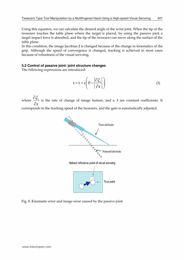
5.2 Control of passive joint: joint structure changes The following expressions are introduced:
k = k + a
x
b t (3)
where xt
is the rate of change of image feature, and a, b are constant coefficients. It
corresponds to the tracking speed of the tweezers, and the gain is automatically adjusted.
Fig. 8. Kinematic error and image error caused by the passive joint.
www.intechopen.com

CuttingEdgeRobotics2010402
Fig. 9. Simple spring model of tweezers.
5.3 Control of passive joint: use of gravity If we regard the tweezers as a simple spring model as in Fig.9, the following expressions can be led:
d0 > db > d0 -kmg (4)
where d0, db are respectively the initial width and the reference width of the tweezers tip, μ is the coefficient of static friction, m is the weight of tweezers, g is an acceleration of gravity, k is the spring constant.
5.4 Target grasp by tweezers The tweezers is controlled with the visual servoing according to the following expressions:
θ ← θ + j (ud − u) (5) where θ is finger joints angle, j is image Jacobian, ud is reference of tips of tweezers width and u is image feature.
5.5 Algorithm flow Fig. 10 shows the algorithm flow in this system. Tweezers grasping phase: The hand grasps the tweezers. Fig.11 shows how the tweezers are grasped in the case of ”precision prismatic thumb-index finger” grasp [3]. The width of
tweezers tips decreases if the fingers touch the tweezers and grasp it. This decrease is observed by the vision system. The operation moves through the following phase. Target tracking phase: The hand manipulates tips of the tweezers to the target. The center of the target and the center of the tweezers tips are set to ξ0, ξt in eqn.(2). When the tip of the tweezers touches the table surface plane where the target is placed, the tracking speed is controlled based on eqn.(3). Target grasping phase: The hand grasps the target with the tweezers. Using eqn.(5), u is set to width of tips of the tweezers and ud is set to the target width. Target moving phase: The hand tracks the target to place it. Using eqn.(2), ξ0 is set to place the target. ξt is set to the center of the tweezers tips. Target releasing phase: The hand releases the target with tweezers. Using eqn.(5), u is the tweezers tips width and ud is set to larger than the target width. Tweezers moving phase: The hand moves the tweezers to place it. Using eqn.(2), ξ0x is set to the initial value of the center of tweezers tip. Now, joint structure between the hand and the tweezers is changed. So by using eqn.(5), the width of the tweezers tip is set to the point contact situation and the kinematic structure of the passive joint is changed. Tweezers releasing phase: Tweezers is released with pushing it.
Fig. 11. Precision Grasp
www.intechopen.com

TweezersTypeToolManipulationbyaMultiingeredHandUsingaHigh-speedVisualServoing 403
Fig. 9. Simple spring model of tweezers.
5.3 Control of passive joint: use of gravity If we regard the tweezers as a simple spring model as in Fig.9, the following expressions can be led:
d0 > db > d0 -kmg (4)
where d0, db are respectively the initial width and the reference width of the tweezers tip, μ is the coefficient of static friction, m is the weight of tweezers, g is an acceleration of gravity, k is the spring constant.
5.4 Target grasp by tweezers The tweezers is controlled with the visual servoing according to the following expressions:
θ ← θ + j (ud − u) (5) where θ is finger joints angle, j is image Jacobian, ud is reference of tips of tweezers width and u is image feature.
5.5 Algorithm flow Fig. 10 shows the algorithm flow in this system. Tweezers grasping phase: The hand grasps the tweezers. Fig.11 shows how the tweezers are grasped in the case of ”precision prismatic thumb-index finger” grasp [3]. The width of
tweezers tips decreases if the fingers touch the tweezers and grasp it. This decrease is observed by the vision system. The operation moves through the following phase. Target tracking phase: The hand manipulates tips of the tweezers to the target. The center of the target and the center of the tweezers tips are set to ξ0, ξt in eqn.(2). When the tip of the tweezers touches the table surface plane where the target is placed, the tracking speed is controlled based on eqn.(3). Target grasping phase: The hand grasps the target with the tweezers. Using eqn.(5), u is set to width of tips of the tweezers and ud is set to the target width. Target moving phase: The hand tracks the target to place it. Using eqn.(2), ξ0 is set to place the target. ξt is set to the center of the tweezers tips. Target releasing phase: The hand releases the target with tweezers. Using eqn.(5), u is the tweezers tips width and ud is set to larger than the target width. Tweezers moving phase: The hand moves the tweezers to place it. Using eqn.(2), ξ0x is set to the initial value of the center of tweezers tip. Now, joint structure between the hand and the tweezers is changed. So by using eqn.(5), the width of the tweezers tip is set to the point contact situation and the kinematic structure of the passive joint is changed. Tweezers releasing phase: Tweezers is released with pushing it.
Fig. 11. Precision Grasp
www.intechopen.com

CuttingEdgeRobotics2010404
Fig. 10. Algorithm flow.
6. Experimental result
We used a single rice grain as a target; its long axis is roughly 5mm and its short axis is roughly 3mm. Another target is a screw; Its is 7.5mm long and 2mm across. Fig.12, Fig.13 and Fig.16 show the results. Fig.12 shows experimental results under different initial conditions. We put the target at the different position for each trial. Regardless of difference in the initial conditions the tweezers grasped the target well. Fig.13. shows experimental results by using the algorithms previously described. The hand grasps the tweezers, grasps the target by tweezers, moves the target for place point and places the tweezers. At 0.5 second, the hand grasps the tweezers. At 2 second, the grabbing state changed. At 2.7 second, the tweezers placed the target. At 3.5 second, the hand changed the grabbing state of tweezers by using gravity. Fig.14 shows the part of the tracking of tweezers to the target. When Y pixel of the center of tweezers tips was 745, the tip of tweezers touched the table plane. After that, the tweezers tips moved along the surface. Normally, if the passive joint structure changes, the tracking speed changes rapidly. But in this case the speed changed smoothly by changing the coefficient of the control method.
Fig. 14. Experimental result of target tracing phase.
Fig. 15. The tweezers tips moving on image plane of Y pixel on gravity use phase. Fig. 15. shows the tips of tweezers on the image plane of Y pixel. This figure shows the hand makes good use of the gravity. Fig. 16. shows experimental results of moving target. The target is moving from opposite side of the hand to the hand, and the hand grasps the target. Regardless of motion of the target, the hand grasps well. Fig. 17 and 18 shows the tips of tweezers and the target on image plane of X pixel and Y pixel. In this case the time between vision recognition and grabbing is 0.1 second. The tips of tweezers follows the target well. This experiment concludes the high speed vision and high speed hand are effective for grabbing in this case.
www.intechopen.com
TweezersTypeToolManipulationbyaMultiingeredHandUsingaHigh-speedVisualServoing 405
Fig. 10. Algorithm flow.
6. Experimental result
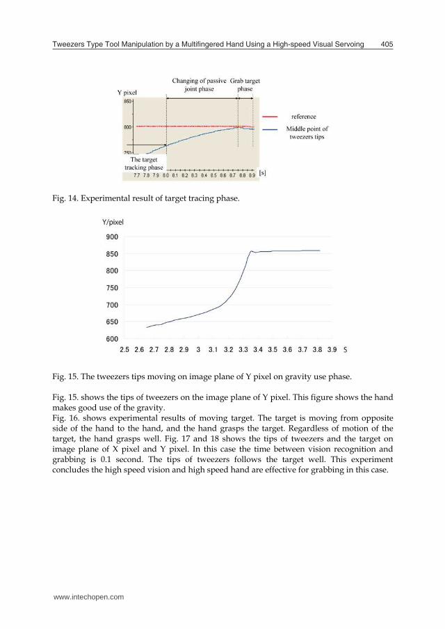
We used a single rice grain as a target; its long axis is roughly 5mm and its short axis is roughly 3mm. Another target is a screw; Its is 7.5mm long and 2mm across. Fig.12, Fig.13 and Fig.16 show the results. Fig.12 shows experimental results under different initial conditions. We put the target at the different position for each trial. Regardless of difference in the initial conditions the tweezers grasped the target well. Fig.13. shows experimental results by using the algorithms previously described. The hand grasps the tweezers, grasps the target by tweezers, moves the target for place point and places the tweezers. At 0.5 second, the hand grasps the tweezers. At 2 second, the grabbing state changed. At 2.7 second, the tweezers placed the target. At 3.5 second, the hand changed the grabbing state of tweezers by using gravity. Fig.14 shows the part of the tracking of tweezers to the target. When Y pixel of the center of tweezers tips was 745, the tip of tweezers touched the table plane. After that, the tweezers tips moved along the surface. Normally, if the passive joint structure changes, the tracking speed changes rapidly. But in this case the speed changed smoothly by changing the coefficient of the control method.
Fig. 14. Experimental result of target tracing phase.
Fig. 15. The tweezers tips moving on image plane of Y pixel on gravity use phase. Fig. 15. shows the tips of tweezers on the image plane of Y pixel. This figure shows the hand makes good use of the gravity. Fig. 16. shows experimental results of moving target. The target is moving from opposite side of the hand to the hand, and the hand grasps the target. Regardless of motion of the target, the hand grasps well. Fig. 17 and 18 shows the tips of tweezers and the target on image plane of X pixel and Y pixel. In this case the time between vision recognition and grabbing is 0.1 second. The tips of tweezers follows the target well. This experiment concludes the high speed vision and high speed hand are effective for grabbing in this case.
www.intechopen.com
CuttingEdgeRobotics2010406
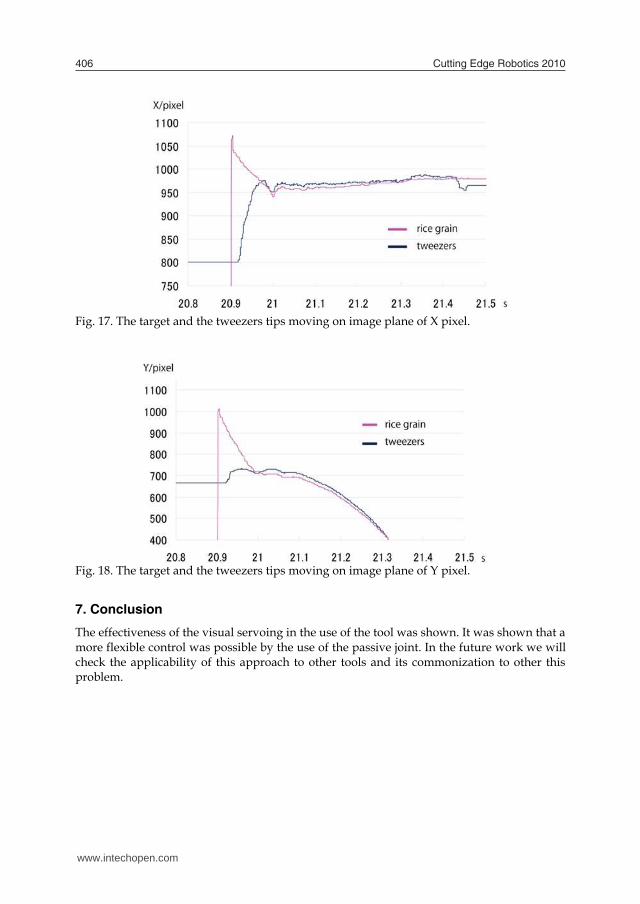
Fig. 17. The target and the tweezers tips moving on image plane of X pixel.
Fig. 18. The target and the tweezers tips moving on image plane of Y pixel.
7. Conclusion
The effectiveness of the visual servoing in the use of the tool was shown. It was shown that a more flexible control was possible by the use of the passive joint. In the future work we will check the applicability of this approach to other tools and its commonization to other this problem.
Fig. 12. Experimental results of different initial conditions.
www.intechopen.com

TweezersTypeToolManipulationbyaMultiingeredHandUsingaHigh-speedVisualServoing 407
Fig. 17. The target and the tweezers tips moving on image plane of X pixel.
Fig. 18. The target and the tweezers tips moving on image plane of Y pixel.
7. Conclusion
The effectiveness of the visual servoing in the use of the tool was shown. It was shown that a more flexible control was possible by the use of the passive joint. In the future work we will check the applicability of this approach to other tools and its commonization to other this problem.
Fig. 12. Experimental results of different initial conditions.
www.intechopen.com

CuttingEdgeRobotics2010408
Fig. 13. Experimental results of rice pick up.
Fig. 16. Experimental results of moving target.
www.intechopen.com

TweezersTypeToolManipulationbyaMultiingeredHandUsingaHigh-speedVisualServoing 409
Fig. 13. Experimental results of rice pick up.
Fig. 16. Experimental results of moving target.
www.intechopen.com

CuttingEdgeRobotics2010410
8. References
[1] A. Bicchi. Hands for dexterous manipulation and robust grasping: A difficult road toward simplicity. IEEE Trans. Robot. and Automat., 16(6):652–662, 2000.
[2] S. Hutchinson, G.D. Hager, P.I. Corke, A tutorial on visual servo IEEE Transactions on Robotics and Automation, Vol. 12, No. 5, pp. 651-670, 1996
[3] M. R. Cutkosky. On grasp choice, grasp models, and the design of hand for manufacturing tasks. Proc. IEEE Int. Conf. Robot. and Automat., Vol. 5, No. 3, pp. 269-279, June 1989.
[4] H.Sugiuchi and T.Morino. A Pair of Scissors Handling Task with Dual Multi-Finger Hand Arm System : Add vision support functions JSME Conference on Robotics and Mechatronics, Vol. 2003 p. 66
[5] H.Kawasaki, T.Mouri, S.Ikenohata, Y.Ohtsuka and T.Endo. Multi-Fingered Haptic Interface Robot Handling Plural Tool Devices: Proceedings of the Second Joint EuroHaptics Conference and Symposium on Haptic Interfaces for Virtual Environment and Teleoperator Systems table of contents Pages 397-402
[6] Kemp, Charles C. and Edsinger, Aaron. Robot Manipulation of Human Tools: Autonomous Detection and Control of Task Relevant Features Proceedings of the Fifth Int Conf on Development and Learning, Special Session on Classifying Activities in Manual Tasks. 2006.
[7] K. Bernardin, K. Ogawara, K. Ikeuchi, R. Dillmann, A Sensor Fusion Approach for Recognizing Continuous Human Grasping Sequences Using Hidden Markov Models, IEEE Transactions on Robotics, Vol. 21, No. 1, pp 47-57, 2005.
[8] A.Namiki, Y.Imai, M.Ishikawa, and M.Kaneko. “Development of a High-speed Multifingered Hand System and Its Application to Catching,” Proc. Int. Conf. Intelligent Robots and Systems, pp. 2666-2671, 2003.
[9] N. Furukawa, T. Senoo, A. Namiki, and M. Ishikawa, Dynamic regrasping using a high-speed multifingered hand and a high-speed vision system, Proc. IEEE Int. Conf. on Robotics and Automation, pp. 181–187, 2006.
[10] T. Ishihara, A. Namiki, M. Ishikawa, and M. Shimojo, Dynamic Pen Spinning Using a High-speed Multifingered Hand with High-speed Tactile Sensor, Proc. IEEE RAS Int. Conf. on Humanoids Robots, pp. 258–263, 2006.
[11] Y. Yamakawa, A. Namiki, M. Ishikawa and M. Shimojo, One-Handed Knotting of a Flexible Rope with a High-Speed Multifingered Hand having Tactile Sensors. Proc. of IEEE/RSJ 2007 Int. Conf. on Intelligent Robots and Systems, pp. 703–708, 2007.
[12] Akio Namiki, Yoshiro Imai, Makoto Kaneko, Masatoshi Ishikawa: Development of a High-speed Multifingered Hand System, International Conference on Intelligent
www.intechopen.com

Cutting Edge Robotics 2010Edited by Vedran Kordic
ISBN 978-953-307-062-9Hard cover, 440 pagesPublisher InTechPublished online 01, September, 2010Published in print edition September, 2010
InTech EuropeUniversity Campus STeP Ri Slavka Krautzeka 83/A 51000 Rijeka, Croatia Phone: +385 (51) 770 447 Fax: +385 (51) 686 166www.intechopen.com
InTech ChinaUnit 405, Office Block, Hotel Equatorial Shanghai No.65, Yan An Road (West), Shanghai, 200040, China
Phone: +86-21-62489820 Fax: +86-21-62489821
Robotics research, especially mobile robotics is a young field. Its roots include many engineering and scientificdisciplines from mechanical, electrical and electronics engineering to computer, cognitive and social sciences.Each of this parent fields is exciting in its own way and has its share in different books. This book is a result ofinspirations and contributions from many researchers worldwide. It presents a collection of a wide range ofresearch results in robotics scientific community. We hope you will enjoy reading the book as much as we haveenjoyed bringing it together for you.
How to referenceIn order to correctly reference this scholarly work, feel free to copy and paste the following:
Satoru Mizusawa, Akio Namiki, Taku Senoo and Masatoshi Ishikawa (2010). Tweezers Type ToolManipulation by a Multifinger Hand Using a High-Speed Visual Servoing, Cutting Edge Robotics 2010, VedranKordic (Ed.), ISBN: 978-953-307-062-9, InTech, Available from: http://www.intechopen.com/books/cutting-edge-robotics-2010/tweezers-type-tool-manipulation-by-a-multifinger-hand-using-a-high-speed-visual-servoing

© 2010 The Author(s). Licensee IntechOpen. This chapter is distributedunder the terms of the Creative Commons Attribution-NonCommercial-ShareAlike-3.0 License, which permits use, distribution and reproduction fornon-commercial purposes, provided the original is properly cited andderivative works building on this content are distributed under the samelicense.