us patent 8,887,785
TRANSCRIPT

(12) United States Patent
US008887785B2
(10) Patent N0.: US 8,887,785 B2 Goth (45) Date of Patent: Nov. 18, 2014
(54) AWNING CONTROL WITH (56) References Cited MULTIDIMENSIONAL MOTION SENSING
U.S. PATENT DOCUMENTS
A * Akers et al‘ ‘ ‘ ‘ ‘ ‘ ‘ ‘ ‘ ‘ ‘ ‘ ‘ ‘ ‘ ‘ ‘ ‘ ‘ ‘ H 4,615,371 A * 10/1986 Clauss . . . . . . . . . . .. 160/22
(73) Assignee: Carefree/Scott Fetzer Co., Broom?eld, 4,981,552 A * 1/1991 Mikkor 433/52 CQ (US) 5,225,748 A * 7/1993 Haring 318/266
6,095,221 A * 8/2000 Frey, Jr. .. 160/67
( * ) Notice: Subject to any disclaimer, the term of this (Continued) patent is extended or adjusted under 35 U_S_C_ 154(1)) by 283 days_ FOREIGN PATENT DOCUMENTS
, EP 1659256 A2 * 5/2006 .............. .. E06B 9/68 (21) Appl' NO" 12/853’299 EP 2003264 A2 12/2008
(22) Filed: Aug. 10’ 2010 OTHER PUBLICATIONS
Australian patent application No. 2010212268, Examiner’s Report (65) Prior Publication Data dated May 30, 2011, 5 pages,
us 2011/0048651 A1 Mar. 3, 2011 PF’WW Exam” T Kathenne MltChen Asszstant Exammer * Scott Demon
(74) Attorney, Agent, or Firm * Tarolli, Sundheim, Covell _ _ & Tummino LLP
Related US. Application Data (57) ABSTRACT
(60) Provisional application No. 61/233,083, ?led on Aug. An awmng control system provides automatic retraction of an 11, 2009~ extended awning upon detection of awning motion in mul
tiple dimensions caused by windy conditions. The awmng (51) Int_ C]_ control system includes a micro-electro-mechanical system
G053 19/042 (200601) (MEMS)-based accelerometer for motion-based auto-retrac E0417 10/06 (200601) tion. A single, combined motion sensor/controller module
may be located in the motor head and connected to switches (52) U's‘ Cl“ and a 12V power source through wires routed along or within
CPC """ " G053 19/0428 (201301); E 04F 10/0614 the awmng framework. The control system operates by gaug (2013-01); E04F 10/0618 (2013-01); E04F ing the vertical, horizontal (inward/outward), and lateral
10/0625 (2013-01); E04F 10/0659 (2013-01); motion of the leading edge or lead rail of the awmng when in E 04F 1 0/0688 (2013.01); G05B 2219/23227 a fully or partially extended position. When persistent motion
(2013.01); GOSB 2219/2653 (2013.01) or gust exceeds preset thresholds, the control system will USPC ............................................... .. 160/66; 160/7 automatically engage the motor to retract the awning. The
(58) Field of Classi?cation Search control system provides full automatic retraction of the CPC .................. .. E04F 10/0659; E04F 10/0692
USPC ........... .. 160/1, 7, 70, 60, 66, 67, 68, 69, 310, 160/22, 78, 79, 55, 65
See application ?le for complete search history.
awning unless halted or interrupted by additional user input. Manual switching also controls the extension and retraction of the awmng.
25 Claims, 14 Drawing Sheets

US 8,887,785 B2 Page 2
(56) References Cited 8,316,910 B2 * 11/2012 Popa et al. .................... .. 160/70 2004/0031321 A1* 2/2004 Orsat ......... .. . 73/170.01
U_S_ PATENT DOCUMENTS 2004/0045683 A1 * 3/2004 Carrillo et al. 160/310 2004/0159407 A1* 8/2004 Girard et al. .................. .. 160/66
6,230,783 B1 * 5/2001 Frey, Jr‘ ““““““““““““ H 160/67 2004/0221965 A1* 11/2004 Wagner et al. ................ .. 160/67 6,273,172 131* 8/2001 Frey """" n 160/67 2005/0282668 A1* 12/2005 Ali et al. .... .. 474/101 6,276,424 Bl * 8/2001 Frey, Jr, ““““““““““““ H 160/67 2006/0113936 A1 * 6/2006 Goth ............. .. 318/280
6,341,638 B1 * 1/2002 Thompson et 31, ,,,,,,,,,,, H 160/67 2007/0113988 A1* 5/2007 Thompson et al. ........... .. 160/70 6,732,018 B2 * 5/2004 ()singa ,,,,,,,,,,,,, ,, , 700/275 2008/0052702 A1* 2/2008 Chuang ....................... .. 717/170
6,843,301 B2 * 1/2005 Carrillo et al. . 160/310 2008/0163685 A1 7/2008 Lapierre 6,971,433 B2 * 12/2005 Wagner et al. 160/67 2011/0048655 A1* 3/2011 Andreasen et al. ......... .. 160/310 7,225,251 B2 * 5/2007 Suzuki . . 709/224 2011/0162861 A1* 7/2011 Borinato et al. 173/176 7,242,162 B2 * 7/2007 G0?1 ~~~~~~~~~~~~ ~~ ~ 318/480 2012/0298315 A1* 11/2012 MarqueZ et al. ................ .. 160/1
7,604,036 B2 * 10/2009 Thompson et al. 160/22 7,729,807 B2 * 6/2010 Guillemot et a1. .......... .. 700/275 * cited by examiner

US. Patent Nov. 18, 2014 Sheet 1 0f 14 US 8,887,785 B2
£11m) ~118a(2) Nisan)
FEGiB HGJC

US 8,887,785 B2 Sheet 2 0f 14 NOV. 18, 2014 US. Patent
All W

US 8,887,785 B2 Sheet 3 0f 14 NOV. 18, 2014 US. Patent
MECRQ CQNTRGLLER " "‘
III! ,,,,,,,, . .I
ll”!
HGQ

US. Patent Nov. 18, 2014 Sheet 4 0f 14 US 8,887,785 B2
320
(i ON RETRACT
f
US. Patent Nov. 18, 2014 Sheet 5 0f 14 US 8,887,785 B2
F564


US 8,887,785 B2 Sheet 7 0f 14 NOV. 18, 2014 US. Patent
3% A
55mm”; 5 $35sz 2 Em, Riggmzé
EQNUME

US. Patent Nov. 18, 2014 Sheet 8 0f 14 US 8,887,785 B2

US. Patent Nov. 18, 2014 Sheet 9 0f 14
LL. :)
553% CD
?km 3 {I}
a W ‘53;_E|§z + w
4“?
‘53 m V‘“
N<£ ll <3“ 955 i5 0
(D 1-“ “Pm o i 2 “k MN > (1%
E>r ' 2 Q ?” 1,an Igz EIL ‘ . : 0““ "J ’9' :3 E
E x >
O‘~§2> E %
§\ 5 8H E {I}
+ 0
LC} 0’3 <3
E“: 555 ? 5?;- mg C; E
“DO wk om ME a
NUT”)
E m E :Dv— L1_
\0 522:5, Q‘NN
52 U Q
03 £3
E i 5—, 0 km N25; 1“ ‘Q‘FLI'J
Q
E I as m> a a
m
g 8 > ,3
- v v v v v v v v v v v v v v v v v v v v v v v v v v v v v v v v v v H + w
E ~~ vvvvv H
CO WAWG WERE LEAD 16AWG WERE LEAD
US 8,887,785 B2

US 8,887,785 B2 Sheet 10 0f 14 NOV. 18, 2014 US. Patent

US 8,887,785 B2 Sheet 11 0f 14 NOV. 18, 2014 US. Patent
cg.
NE '02 '02 www 03
~ $22
@E IJ
E255 gazes. oz Fwme SE CQEEEQSN, 9350c
3K
> Q2 Ema somHEwEUQ/q @Zwumm Y will
T: :2:po
$5; gm $2
gme 362 V E950
H525 LBEoE we“ H +
mom ESE 2mBu< can +
Y UQmEEoo @555 GEEK
US. Patent Nov. 18, 2014 Sheet 12 0f 14 US 8,887,785 B2
859 Receive Extend /— Awning Signet
Actuate Mater
894 l iv‘ieriiter Circuit
Current
\
\ 896
Persistent Signet?
808 816
f Meter Shut (lift $12
HGB

US. Patent Nov. 18, 2014 Sheet 13 0f 14 US 8,887,785 B2
Connect Dongie to Ground, Extend, & 999 Retreat Leeds of f—
992 ivtiorooontroiier
i Estebiish
f Computer/Dongie Communication
i Activate Power
f Suppiy to 806 ivtiorooontroiier
i Estabiisti Computer!
Miorocontreiier f Communication
808 Within “Listening” Window
i identity New
I Firmware Fiie
Unioad New Firmware to
f iv‘iioreoontroiier
I Disconnect
904
919
Q12
914
F563

US. Patent NOV. 18, 2014
$02
Connect Dengie to Ground, Extend, & Retreat Leads of Micreeentreiier
i
f 1064
Estabiish Computer/Dengie Cemmuriicatien
i
f 1006
Activate Fewer Suppiy te
Miereeeritreiier
i
f 1998
Estabiish Cemputeri
Miereeentreiier Cemmuriicatien Within “Listening”
Windew
t
f Identify Data Capture Fiie
101i)
f Receive ivietien Sensor Bate
1912 i
f 1614
Graphicaiiy Dispiay Motien Senser Data
i
f Store Motion Senser Bate
1916
1018
$top Capture
Dissentith
1922
Sheet 14 0f 14
YES
Sta rt Capture Command?
US 8,887,785 B2
1626
HEW

US 8,887,785 B2 1
AWNING CONTROL WITH MULTIDIMENSIONAL MOTION SENSING
CROSS REFERENCE TO RELATED APPLICATIONS
This application claims the bene?t of priority pursuant to 35 U.S.C. §119(e) of US. provisional application No. 61/233,083 ?led 11 Aug. 2009 entitled “Awning control with multidimensional motion sensing,” which is hereby incorpo rated herein by reference in its entirety.
TECHNICAL FIELD
The technology described herein relates to control systems for retractable awnings.
BACKGROUND
Many retractable awning systems, for example, as mounted on the sides of motor homes or over patios or win dows, have automatic retraction systems that activate a motor or retract the awning under severe wind conditions that might damage the awning framework, fabric, or structure to which the awning is mounted. Current motion-based, auto-retrac tion control systems for automatic awning retraction consist of separate modules for motor control, radio frequency inter face, and motion sensing. Further, such systems can only detect severe motion of the awning (e. g., due to wind gusts) in a single dimension.
The information included in this Background section of the speci?cation, including any references cited herein and any description or discussion thereof, is included for technical reference purposes only and is not to be regarded subject matter by which the scope of the invention is to be bound.
SUMMARY
The awning control system described herein provides for automatic retraction of an extended awning upon detection of awning motion in multiple dimensions caused by windy con ditions. The awning control system includes a micro-electro mechanical system (MEMS)-based accelerometer technol ogy for motion-based auto -retraction. The motion sensor may be located in the motor head. The control system operates by gauging the vertical, horizontal (inward/ outward), and lateral motion of the leading edge or lead rail of the awning when in a fully or partially extended position. When persistent motion exceeds a factory preset threshold, the control system will automatically engage the motor to retract the awning. A single sensor/ controller module may be located in the motor head and connected to switches and a 12V power source through wires routed along or within the awning framework. Manual switching may also be used to control the extension and retraction of the awning. The control system may provide for full automatic retraction of the awning unless halted or interrupted by additional user input.
In one implementation, the entire control system is pro vided in a single physical device, inclusive of the motion sensor, located in the leading edge of an awning. User input options may include extension and retraction awning opera tion via a hardwired switch or radio frequency remote control. The control system may also accept user input of a motion sensitivity level control for the threshold for auto-retraction.
In another embodiment, the accelerometer-based motion sensor may be provided as a replacement for current piezo electric-based motion sensors in mass-spring-based acceler
20
25
30
35
40
45
50
55
60
65
2 ometers. The accelerometer-based replacement control sys tem may be a plug-and-play replacement component with the added functionality of multi-axis motion sensing. This new accelerometer-based system enhances the current functional ity to allow measurement of lateral, horizontal, and vertical awning motion. The output signal may be formed as a scaled, “anemometer-like” switched transistor output that is essen tially the same output of anemometers and piezoelectric sen sors, but may also be provided as a proportional signal result ing from multi-axis awning motion measurement.
This Summary is provided to introduce a selection of con cepts in a simpli?ed form that are further described below in the Detailed Description. This Summary is not intended to identify key features or essential features of the claimed sub ject matter, nor is it intended to be used to limit the scope of the claimed subject matter. A more extensive presentation of features, details, utilities, and advantages of the present invention is provided in the following written description of various embodiments of the invention, illustrated in the accompanying drawings, and de?ned in the appended claims.
BRIEF DESCRIPTION OF THE DRAWINGS
FIG. 1A is a schematic diagram of an implementation of a retractable awning equipped with a multidimensional motion detector.
FIG. 1B is a front elevation view of an implementation of a control switch for the retractable awning of FIG. 1A.
FIG. 1C is a side elevation view of an implementation of a control switch for the retractable awning of FIG. 1A.
FIG. 1D is a front plan view of a motor head assembly on the leading edge of the awning with the housing removed and certain wiring routes shown in phantom.
FIG. 2 is an isometric view of an alternate implementation of a motorized retractable awning with additional control components presented schematically.
FIG. 3 is a front elevation view of an alternate implemen tation of a control switch for a retractable awning.
FIG. 4 is a isometric representation diagramming wiring leads and switch connections for a potted electrical control assembly for the retractable awning of FIG. 1A.
FIG. 5A is a schematic diagram of a ?rst portion of an implementation of a control circuit for controlling the retract able awning of FIG. 1A.
FIG. 5B is a schematic diagram of a second portion of an implementation of a control circuit for controlling the retract able awning of FIG. 1A.
FIG. 5C is a schematic diagram of a third portion of an implementation of a control circuit for controlling the retract able awning of FIG. 1A.
FIG. 5D is a schematic diagram of a fourth portion of an implementation of a control circuit for controlling the retract able awning of FIG. 1A.
FIG. 6 is a schematic diagram of a multidimensional motion detector as used in the control circuit of FIG. 4.
FIG. 7 is a ?ow diagram of an exemplary control process for retraction of an awning.
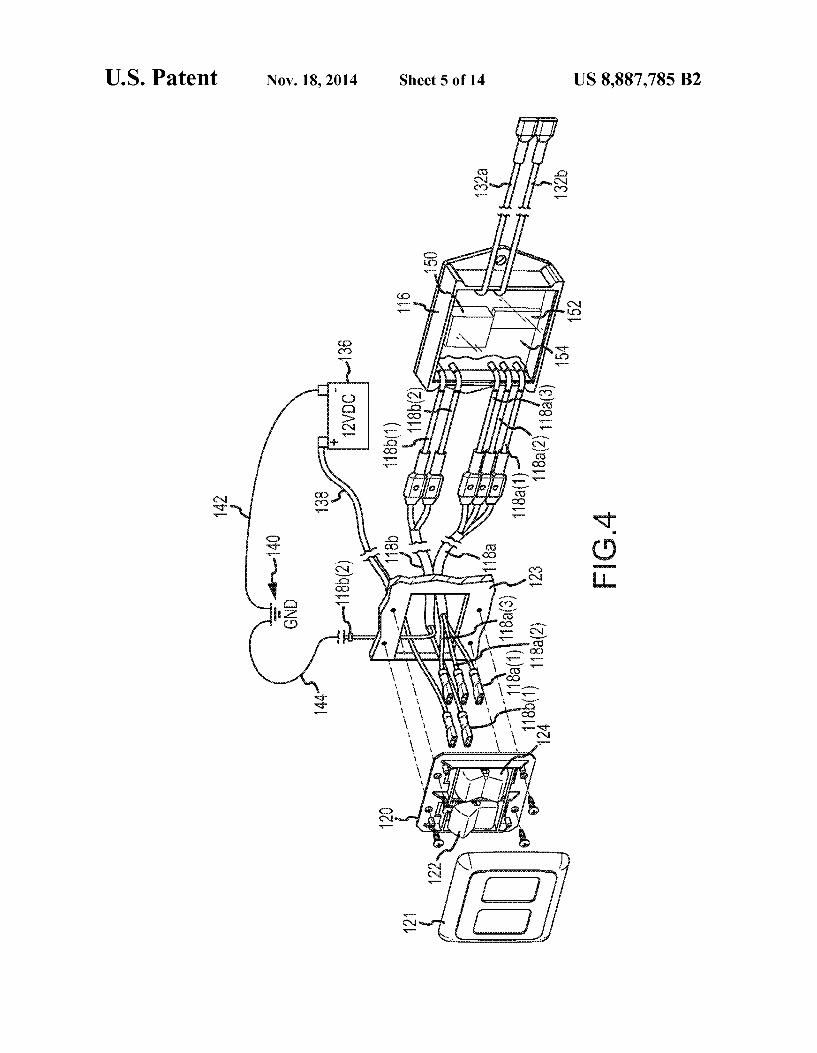
FIG. 8 is a ?ow diagram of an exemplary control process for extension of an awning.
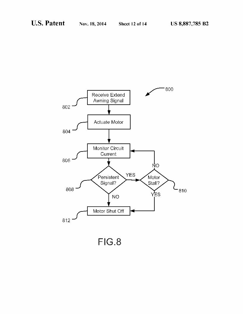
FIG. 9 is a ?ow diagram of an exemplary control process for updating the ?rmware in a potted microcontroller of an awning control system.
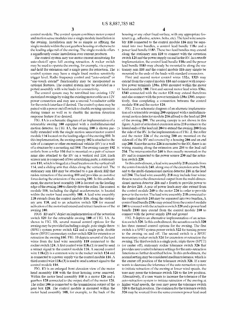
FIG. 10 is a ?ow diagram of an exemplary control process for receiving real-time motion sensor date from a potted microcontroller of an awning control system.
DETAILED DESCRIPTION
An electrical control system incorporating a multidimen sional motion detector may be used as an auto-retract awning
US 8,887,785 B2 3
control module. The control system combines motor control and motion sense modules into a single module installation in the awning. Installation may be as simple as af?xing the single module within the cast gearbox housing or otherwise to the leading edge rail of the awning. The single module offers a signi?cantly easier installation over current products.
The control system may use motor current monitoring for auto-shutoff upon full awning retraction. A rocker switch may be used to operate the awning, for example, via a press and-hold for extension and a single press for retraction. The control system may have a single ?xed motion sensitivity trigger level. Radio frequency control and “auto-extend” or “one-touch extend” functionality may be incorporated as optional features. The control system may be provided as a potted assembly with wire leads for connectivity.
The control system may be retro?tted into existing 12V motorized awnings by using the existing motor cable as a 12V power connection and may use a second 3-conductor cable for the switch interface if desired. The control system may be paired with a power on/ off switch to disable awning operation during transit as well as to disable the motion detection response feature if so desired.
FIG. 1A is a schematic diagram of an implementation of a retractable awning 100 equipped with a multidimensional motion detector. In FIG. 1A, the awning 100 is shown par tially extended with the single motion sensor/motor control module 116 located on the leading edge of the awning 100. In this implementation, the awning canopy 102 is attached to the side of a camper or other recreational vehicle (RV) or a wall of a structure by a mounting rail 104. The awning canopy 102 unfurls from a roller 106 that is mounted on a pair of scissor arms also attached to the RV on a vertical rail 114. Each scissor arm is composed of two articulating parts, a stationary arm 110, which is hinged at a ?xed location on the vertical rail 114, and a sliding arm that slides along the vertical rail. The stationary arm 110 may be attached to a gas shock 112 that resists retraction of the awning 100 and provides an assistive force during the extension of the awning 100. In this embodi ment, the motor head assembly 108 is located on the leading edge of the awning 100 to directly drive the roller. The control module 116, including the digital accelerometer, is located within the motor head assembly 108. A lead wire assembly 118 extends from the control module 116, along the station ary arm 110, and to an actuation switch 120 for manual activation of the motorized extend and retract functions of the awning 100.
FIGS. 1B and C depict an implementation of the actuation switch 120 for the retractable awning 100 of FIG. 1A. As shown in FIG. 1B, several manual control options for the awning may be provided including a single, pole single throw (SPST) system power switch 122 and a single pole, double throw (SPDT) momentary rocker switch 124 for extension or retraction the awning 100. FIG. 10 depicts several of the lead wires from the lead wire assembly 118 connected to the rocker switch 124. A ?rst control wire 118a(1) is used to send a retract signal to the control module 116. A second control wire 118a(2) is a common wire to the rocker switch 124 and is connected to a power supply via the control module 116. A third control wire 118a(3) is used to send a retract signal to the control module 116.
FIG. 1D is an enlarged front elevation view of the motor head assembly 108 with the front housing cover removed. Within the motor head assembly 108 is a motor 126 and a gearbox 128 connected to the output shaft of the motor 126. The roller 106 is connected to the transmission output of the gear box 128. The control module is mounted within the motor head assembly 108, for example, to the back of the
20
25
30
35
40
45
50
55
60
65
4 housing or any other ?xed surface, with any appropriate fas tener (e.g., adhesive, screws, bolts, etc). The lead wire assem bly 118 connected to the control module 116 may be sepa rated into two bundles, a control lead bundle 118a and a power lead bundle 1181). These two lead bundles may extend along the stationary arm 110 to connect with the actuation switch 120 and the power supply on and in the RV. In a retro?t implementation, the control lead bundle 118a and the power lead bundle 1181) may already be mounted to along the sta tionary arm 110 and the control module 116 may simple be mounted to the ends of the leads with standard connectors.
First and second motor control wires 132a, 1321) may extend from the control module 116 and connect with respec tive power terminals 130a, 1301) mounted within the motor head assembly 108. First and second motor lead wires 134a, 1341) connected with the motor 126 may extend therefrom and also connect with the power terminals 130a 130b, respec tively, thus completing a connection between the control module 116 and the motor 126.
FIG. 2 is a schematic diagram of an alternate implementa tion of a retractable awning 200 equipped with a multidimen sional motion detector module 216 af?xed to the lead rail 204 of the awning 200. The awning canopy is not shown in this ?gure. A pair of articulated extension arms 210 connect to the lateral ends of the lead rail 204 to extend the awning 200 from the side of the RV. In the implementation of FIG. 2, the roller and the motor 226 of the awning 200 are mounted on the sidewall of the RV and covered by a housing 206 and an end cap 208. Since the motor 226 is mounted to the RV, there is no wiring running along the extension arm 210 to the lead rail 204. The microcontroller 240 is thus usually mounted on the RV and is connected to the power source 230 and the actua tion switch 220.
In this embodiment, a lead wire assembly 218 extends from the control module 240, along one of the extension arms 210, and to the multi-dimensional motion detector 216 in the lead rail 204. The lead wire assembly 218 may include four wires: three to receive the dimensional output from the multi-dimen sional motion detector 216 and a fourth to provide power to the device 216. A pair of power leads may also extend from the control module 240 to the motor 226 in order to provide power to the motor. The lead wire assembly 218 connected to the control module 240 may be separated into two bundles, A control lead bundle 218a may extend from the control module 240 to connect with the actuation switch 220 and a power lead bundle 2181) may extend from the control module 240 to connect with the power supply 230 and ground.
FIG. 3 depicts an alternative implementation of an actua tion switch 320. In this embodiment, the actuation switch 320 has three manual control options for the awning. The ?rst switch is a SPST system power switch 322 for turning power to the awning on and off. The second switch is a SPDT momentary rocker switch 324 for extension or retraction the awning. The third switch is a single pole, triple throw (SPTT) (or center off), stationary rocker tolerance switch 326 that provides user control tolerance settings for the auto-retraction functions as further described below. In this embodiment, the normal setting may be considered medium tolerance, which is the center off position of the tolerance switch 326. If a user wants to decrease the tolerance of the auto-retraction system to initiate retraction of the awning at lower wind speeds, the user may press the tolerance switch 326 to the low position. Alternatively, if a user wants to increase the tolerance of the auto-retraction system to initiate retraction of the awning at higher wind speeds, the user may press the tolerance switch 326 to the high position. The common for the tolerance switch 326 may be sourced from the same common power lead used

US 8,887,785 B2 5
for the extension/retraction switch 324. At least two addi tional wires from the tolerance switch 326 to the microcon troller in the control assembly would be required. Signals from the tolerance switch 326 would constitute an instruction for the microcontroller to either add or subtract a value from the standard threshold values used to determine whether to actuate the auto -retraction feature as further described below.
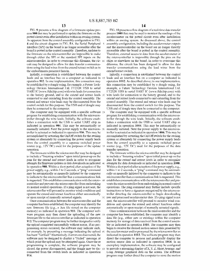
FIG. 4 is a schematic diagram of component wiring for a potted electrical control module 116 for the retractable awning of FIG. 1A. The control system module 116 is shown connected with a 12V power supply 136, a power switch 122 (with a faceplate 121 removed), a manual extension/retrac tion switch 124, and with motor control wires 132a, 1321) extending to an awning motor (not shown). Among the com ponents on the circuit board 154 of the control system module 116 are a microcontroller 150 and a multi-dimensional
motion detector (accelerometer) chip 152. The circuit board 154, the chips 150, 152 mounted thereon, and all the lead connections are potted in a waterproof, shock resistant epoxy resin, polyurethane, silicone, or other appropriate material in order to protect the control module 116 from weather, travel vibration, and extreme motion (e.g., due to wind gusts).
In addition to the motor control wires 132a, 132b, the ?rst, second, and third control wires 118a(1, 2, 3) and the ?rst and second power supply wires 118b(1, 2) also extend from the control module 116 for connection with the power supply 136 and actutation switches 120. The control wires 118a(1, 2, 3) and the power supply wires 118b(1, 2) may be provided on the control module 116 as short tails with connectors that are con?gured to connect with corresponding connectors on a control lead bundle 118a and a power lead bundle 11819 in order to enhance the ease of installation and replacement of the control module 116 if necessary. The control lead bundle 118a and the power lead bundle 1181) travel from the motor head assembly 108 on the leading edge of the awning 100 along the extension arm 110, and to the box of actuation switches 120 mounted to a surface 123 of the RV where the individual wires may again be connected with shorter tails extending from the actuation switches 120 and the power supply. As shown in the implementation of FIG. 4, the ?rst control
wire 118a(1) is connected to the extend lead on the extend retract switch 124 (see FIG. 10). The second control wire 118a(2) functions as the common lead on the extend retract switch 124. The third control wire 118a(3) is connected to the retract lead on the extend retract switch 124. The ?rst power supply wire 118b(1) is attached to a ?rst terminal of the system power switch 122 and the second power supply wire 118b(2) is connected to a ground lead 144 that is connected to ground 140. A power supply lead 138 is connected between a second terminal of the power supply switch 122 and the positive terminal of the power supply 136 (e. g., a 12V battery in the RV). The negative terminal of the power supply 136 is also connected to ground 140 via a ground wire 142.
FIG. 5A is a schematic diagram of a ?rst portion of an implementation of a control circuit 500 for controlling the retractable awning of FIG. 1A. The circuit in FIG. 5A includes a microprocessor in the form of a microcontroller 502. In an exemplary implementation, the microcontroller may be a programmable interface controller, e.g., a PIC18F23K20 chip. The microcontroller 502 has a voltage input 504 and receives three motion inputs 530a, 530b, 5300 corresponding to each of the three-dimensional (Z, Y, X) motion readings generated by the accelerometer 516 (see FIG. 5B) as well as a current input signal 542 from a current monitor 540 (see FIG. 5C) within the circuit 500. The micro controller 502 outputs motor control signals 518b(1), 518b(2)
20
25
30
35
40
45
50
55
60
65
6 for controlling the motor based upon the input signals. The output signals 518b(1), 518b(2) may each be conditioned by a voltage divider 512, 514 and a junction transistor 513, 515 to isolate the microcontroller from the higher line voltage used to actuate the relay 536 and motors (see FIG. 5C). A serial peripheral interface bus 506 may be connected to the microcontroller 502 for initial installation of ?rmware on the microcontroller before the circuit 500 is potted within the control assembly.
In this implementation, the microcontroller 502 received two additional control inputs from the actuator switch corre sponding to the extend lead 518a(1) and the retract lead 518a(3). The 12V DC power supply 510 from a battery source (e.g., the RV battery) is additionally shown in FIG. 5A and is supplied to the common lead 518a(2) that provides a voltage source for each of the extend lead 518a(1) and the retract lead 518a(3). The signals from each of the extend and retract leads 518a(1), 518a(3) are conditioned before reaching the micro controller 502, in part in order to allow for ping commands to place the microcontroller in an update or data transfer mode (as further explained below) as well as to provide for data transfer over the extend and retract leads 518a(1), 518a(3). The portion 506 of the circuit 500 connecting the extend
lead 518a(1) to the microcontroller 502 is bidirectional allow ing for data transfer from the microcontroller in addition to signal inputs. This extend lead portion 506 may have a metal oxide varistor or other transient voltage suppressor 520, a voltage divider 521, and a diode clamp 522 for line condi tioning. The retract lead portion 508 may similarly have a transient voltage suppressor 524, a voltage divider 525, and a diode clamp 526 for line conditioning as well as other com ponents. In particular, the retract lead portion 508 may addi tionally have a bipolar junction transistor 528, rendering the retract lead portion 508 unidirectional allowing only signal transmission to the microcontroller 502, but not data transfer from the microcontroller 502.
FIG. 5B is a schematic diagram of a second portion of an implementation of the control circuit 500 for controlling the retractable awning of FIG. 1A. The circuit in FIG. 5B includes the MEMS-based motion detector or accelerometer 516 and shows three output lines 530a, 530b, 5300 corre sponding to three-dimensional motion data. In one imple mentation, the accelerometer 516 may be an ADXL33 SBCPZ chip. Each of the output lines 530a, 530b, 5300 from the accelerometer 516 may be conditioned with various compo nents, including, for example, an operational ampli?er func tioning as a voltage follower buffer 532 in order to ensure clean output signals from the accelerometer 516.
FIG. 5C is a schematic diagram of a third portion of an implementation of the control circuit 500 for controlling the retractable awning of FIG. 1A. The circuit portion of FIG. 5C includes a relay 536 for operating the motor and a current sensor 540 that monitors motor current draw. The relay 536 receives the motor control signals 518b(1), 518b(2) from the microcontroller 502 as increased from line level signals by additional power from the power supply to direct operation of the motor in either a forward/ extend direction or a reverse/ retract direction. Flyback diodes 538 may be used between the induction coils of the relay and the power supply to protect the power supply from voltage spikes. The outputs of the relay 536 connect to two motor leads 534a, 5341) to actuate the motor in either a forward or reverse direction. A current monitor chip 540 may be placed in series with one of the motor leads 534a, 5341) from the relay 536 to the motor. The current sense chip 540 monitors the level of current drawn by the motor to identify conditions such as motor stall or no draw indicating malfunction. Output from the current monitor chip
US 8,887,785 B2 7
540 is used as an input in the microcontroller 502 in the determination of various motor control functions as further described below.
FIG. 5D is a schematic diagram of a fourth portion of an implementation of a control circuit for controlling the retract able awning of FIG. 1A. The circuit portion in FIG. 5D details a set of voltage regulators that provide constant and appro priate voltage levels to the circuit. As previously shown in FIG. 4, the ?rst power lead 518b(1) is connected to a 12V bus line 548 conditioned from the 12V power supply 546 (e. g., an RV battery) while the second power lead 518b(2) connected to ground. A ?rst positive voltage regulator chip 550 trans forms power from the 12V bus line 548 and outputs to a 5V bus line 552 for providing required power to the current sense chip 540. A second positive voltage regulator chip 554 steps the voltage down from the 5V output of the ?rst positive voltage regulator chip 550 and outputs to a 3.3V bus line 556 for providing required power to the microcontroller 502, the accelerometer 516, and other components. The circuit portion in FIG. 5D further depicts a conditioning circuit 544 for the 3.3V bus line.
FIG. 6 is a schematic diagram of a multidimensional motion detector or accelerometer 616 as used in the control circuit of FIG. 5B. In one implementation, the multidimen sional motion detector 616 may be a complete three-axis acceleration measurement system (e.g., an ADXL335 chip). The detector chip may have a measurement range of :3 g minimum. In one embodiment, the detector chip contains a polysilicon surface, micro-machined sensor 602 and signal conditioning circuitry to implement an open-loop accelera tion measurement architecture. The output 630a, 630b, 6300 of the MEMS accelerometer 616 may be analog voltages that are proportional to the measured acceleration. The multidi mensional motion detector 616 thus acts as an accelerometer that can measure the static acceleration of gravity in tilt sensing applications as well as dynamic acceleration result ing from motion, shock, or vibration. In other implementa tions, a digital output MEMS device may be used that provides data output representative of acceleration in each of three dimensions.
The sensor may be a polysilicon surface, micro-machined structure built on top of a silicon wafer. Polysilicon springs suspend the structure over the surface of the wafer and pro vide a resistance against acceleration forces. De?ection of the structure is measured using a differential capacitor that con sists of independent ?xed plates and plates attached to the moving mass. The ?xed plates are driven by 180° out-of phase square waves. Acceleration de?ects the moving mass and unbalances the differential capacitor resulting in a sensor output whose amplitude is proportional to acceleration. The sensor output is ampli?ed by an AC ampli?er 604. Phase sensitive demodulation techniques in a demodulator 606 may then be used to determine the magnitude and direction of the acceleration. The demodulator output may be ampli?ed using individual output ampli?ers 608a, 608b, 6080 for each axis and brought off-chip through a resistor. The user may then set the signal bandwidth of the device by adding a capacitor. This ?ltering improves measurement resolution and helps prevent aliasing. Because the detector uses a single structure for sens ing the X-, Y-, and Z-axes, the sense directions of the three axes are highly orthogonal and have little cross-axis sensitiv ity.
Both automatic and manual retraction of a motorized awning may be controlled by a microcontroller receiving both accelerometer data and manual input as described above. Firmware in the microcontroller may be used to implement such processes. FIG. 7 is a ?ow diagram of exemplary process
20
25
30
35
40
45
50
55
60
65
8 steps 700 that may be embodied in ?rmware on the micro controller for controlling the retraction process 700. As shown in FIG. 7, upon receipt of an awning retract command as indicated in operation 7024either a manual input signal by a user selecting a switch or an automatic input signal based upon motion information from the accelerometer devicei the controller actuates the motor in a retraction direction as indicated in operation 704.
During motor operation, circuit current may be constantly monitored against various threshold values as indicated in operation 706 that indicate a need for an awning retraction auto-shutoff function. Such an auto-shutoff of the retraction function may be provided to disconnect the power to the motor during a retraction to prevent damage to the motor or other awning components. In a ?rst instance, the circuit cur rent may be monitored to detect the likelihood of a motor stall as indicated in decision operation 708. A motor stall is indi cated by a large current draw which re?ects a strong resis tance to further retraction of the awning. Such a resistance may be caused by a number of factors including, for example, a locked rotor condition indicating full retraction of the awning, a physical impediment to awning retraction (e.g., a tree branch or camping equipment), a wind gust, or a spring force in the awning that holds the awning in a ?xed position.
In an exemplary embodiment, the ?rmware may be pro grammed with a number of threshold values in order to detect a stall.
A Minimum Current Value (MCV) may be set as the mini mum retraction current tracked and averaged over a short time to ?lter noise and act as ?oating baseline value to which a motor-speci?c value is added (see the OCT value described below) for an upper threshold value indicative of a stall. Since the MCV is an average value, the awning position may not be retained during a power cycle. As such, if a retract event occurs immediately following power up, there is no stored MCV to reference in conjunction with the motor-speci?c value and, as such, will allow the awning motor to draw full stall current until a timer expires (see the MRT value described below). This may cause overheating and trip the motor’ s thermal fuse. In order to prevent this from occurring, several options may be con?gured.
In a ?rst option, a brief, timed, auto-extension may occur upon power-up, just long enough to allow the MCV to be set, followed by an auto-retraction. In a second option, a default MCV value may be loaded during power cycle start-up. This default value could be the last calculated MCV from a prior usage or it may be a set value. This method is simpler, but does not auto-calibrate the auto-shutoff routine to allow for vari ances in motors and power supply levels. This option also risks not properly detecting stall under all conditions, but the risk can be mitigated or possibly eliminated via set of a minimal MCV values speci?c to various motor types.
In one implementation, a ?oor value (e.g., 3 A) for the MCV may be also used to prevent nuisance stall in the case of a billow event during initial awning retraction. The initial value would then be updated over time based upon average measured values. For example, the retraction current is high est during initial phase of gas shock compression (e.g., in the 7-8 A range at 13.6V) but quickly decreases as gas shocks are compressed. A billow event during initial retraction reduces current to within the 1-2 A range since the wind lifts the canopy and further compresses the gas shocks, thus drasti cally reducing the motor load. Once the canopy relaxes and the gas shocks are extended, the motor load is returned to normal, the current increases, and a stall is detected. Utilizing