vehicle high speed stability analysis throughintegrated
TRANSCRIPT
Vehicle High Speed Stability Analysis through
Nur Alyani Nadhiya1, Fitri Yakub2,*, Hatta Ariff3, Azizul Azizan4, Zainuddin A. Rasit5, Sheikh Ahmad Zaki6, Abdul Yasser Abd Fattah7,Yasuchika Mori8
1,2,3,5,6Malaysia-Japan International Institute of Technology,Universiti Teknologi Malaysia, Kuala Lumpur 4,7Razak Faculty of Technology and Informatics, Universiti Teknologi Malaysia, Kuala Lumpur, Malaysia
8Transportation Systems & Electric Co., Ltd, 3-13-2, Takadanobaba, Shinjuku, 169-0075, [email protected], 2,*[email protected], [email protected], [email protected], [email protected],
[email protected], [email protected]
Abstract— This paper extends the analysis of Yakub et. al [1], by suggesting an integrated control which includes an active aerodynamic control and differential braking control to enhance high speed vehicle dynamics stability. Two aerodynamic surfaces are attached to the roof of the vehicle and servo controlled separately in real time. A hierarchical control structure which is composed of an upper and a lower controller. In the upper controller, the additional yaw moment required for stability control is determined by sliding mode control with the consideration of driver inputs, vehicle dynamic and the limitation of road adhesion. In the lower controller, a control strategy is designed to coordinate differential brake and active aerodynamic control, and an optimal control allocation algorithm is adopted to distribute the brake pressure of each wheel. Two double lane change tests on dry and wet road performed to study the effectiveness of the control algorithm in Simulink simulation. The results show, the proposed control strategy can effectively improve the vehicle dynamics stability and tire workload usage.Keywords—vehicle dynamics stability, active aerodynamic control, differential braking control, control allocation, tire workload
I. INTRODUCTION
As an active safety technology, vehicle dynamics stability control plays a vital role in improving driving performance. It has always been the focus of automotive safety research, resulting in a rich literature. To improve vehicle stability performance, three types of stability control systems havebeen proposed and developed [2]. Differential braking systems, which utilize the hydraulic brake system on the vehicle to generate an additional yaw moment by imposing uneven brake forces on right-side and left-side wheels, have received the most attention from researchers and automobile manufacturers through different control schemes [3-5].
On the other hand, active front steering systems, which overlay a steering torque or a steering angle by a DC motor, have gradually received attention from academic researchers in the past decades with different scenario analysis i.e. collision avoidance and double lane change [6-8]. Beside, active torque distribution systems, which utilize active driving/braking torque control technology to independently control the torque distributed to each in-wheel motor, has been extensively studied in the recent past with the improvements on electric motor and motor controller [9-11].
To realize the optimal control of the vehicle, a number of integrated vehicle dynamics control system have been
developed such as integrated active front steering and direct yaw moment control, nonlinear model predictive controller, coordinated control of electronic stability control [12-14].
However, these control systems are adjust vehicle’s dynamics or trajectory by changing the tire forces. One major problem arise from this: tire forces are at the risk of saturation, especially under critical conditions. In the last decade, advances in electromechanical technology and decreases in the cost of actuators have make it possible to provide a new path to improve vehicle dynamics under high speed condition. The active aerodynamic surfaces control is a new and effective method to solve the problem of tire saturation [15].
In the past, the use of active aerodynamic surfaces (AAS) for improving vehicles’ performance i.e. road holding,braking, and handling have investigated by scholars and automotive manufacturers [16-17]. The capability of AAS to compensate the overall downward force to improve the road holding and handling of a race car in a lane change maneuver and driving on wet roads has been investigated [18].
The drawback of active aerodynamic control is that AAScan provide sufficient aerodynamic forces to adjust vehicle’s dynamics only when the relative speed of the vehicle and air is high enough. In this study, to overcome the above mentioned drawbacks, a new integrated control method using active aerodynamic control and differential braking control is proposed to improve the vehicle dynamics stability.
Two aerodynamic surfaces are attached to the roof of the vehicle and servo-controlled separately in real-time. In the upper controller, a bicycle model of the vehicle and a simplified tire model are used to determine the desired dynamics, and a sliding mode controller is designed to calculate the additional yaw moment for tracking the desired dynamics response. In the lower controller, a control strategy is presented to coordinate differential braking control and active aerodynamic control, and an optimal control allocation algorithm is adopted to distribute the brake pressure of each wheel. The effectiveness of the proposed control method is validated through Simulink simulation.
II. SYSTEM DESIGN
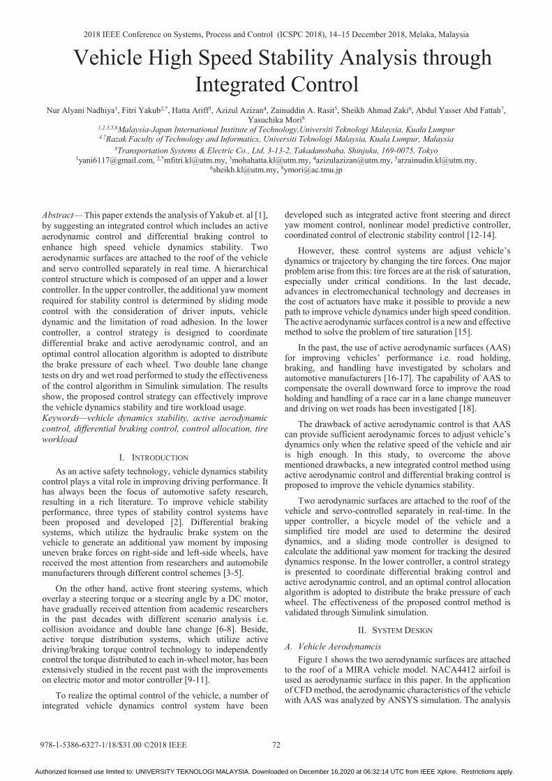
A. Vehicle Aerodynamcis Figure 1 shows the two aerodynamic surfaces are attached
to the roof of a MIRA vehicle model. NACA4412 airfoil is used as aerodynamic surface in this paper. In the application of CFD method, the aerodynamic characteristics of the vehicle with AAS was analyzed by ANSYS simulation. The analysis
Authorized licensed use limited to: UNIVERSITY TEKNOLOGI MALAYSIA. Downloaded on December 16,2020 at 06:32:14 UTC from IEEE Xplore. Restrictions apply.
method of the aerodynamic characteristics comprises the following steps: setting the angle of attack of two aerodynamic surfaces as 0°, and then varying the angle of attack of one aerodynamic surface from 0° to 90° while the angle of attack of the other aerodynamic surface is still 0° and recording the lift and drag coefficient of the vehicle. It is assumed that there is no wind on the ground. The analysis results are shown in Fig. 2.
Fig. 1. MIRA vehicle model with AAS
(a) (b)
Fig. 2. Aerodynamic characteristics of vehicle with AAS (a) lift coefficient (b) drag coefficient
2 21 1( ) , ( )2 2d d r l l rF C A v F C A v (1)
where Fd is the air drag; Fl is the air lift; Cd and Cl are drag coefficient and lift coefficient which depend on the Reynolds number, airfoil shape, roughness and the angle of attack (θ); A is the projection area of the vehicle; ρ is the air density; vr is the relative speed of vehicle and air flow. The dynamic response of the active aerodynamic surfaces can be described as a first-order lag with τ is a time constant (τ=0.005).
1( )1sG s
s(2)
B. Vehicle Model
We employed the same vehicle model as in [1]. Figure 3 illustrate the 2-DoF vehicle model, is considered as reference vehicle model for vehicle dynamic stability control. The vehicle lateral and yaw motion of 2-DoF for the nonlinear vehicle model, the dynamics motion incorporate with the disturbances impact are expressed in planar characteristics equations of linear vehicle motion can be given as follows:
2: ( ) 2 2 ( )y yf yr s r f uF m y x F F m h l l m2yf yr s r f uF F m h l l m22 2 ( )yf yr syr2 r f uu)h uF m h 22 2 (yr s2 hy ) 2) 2) 2 (3)
, , , ,: ( )22 2 ( ) ( )
wz zz xf l xf r xr l xr r
f yf r yr r f u
tM I F F F F
l F l F l l m y x2
t
y )
(4)
The slip angle for the front and rear wheels, with a small angle assumption, are given such that:
fx
fyf v
lv , y rr
x
v l
v(5)
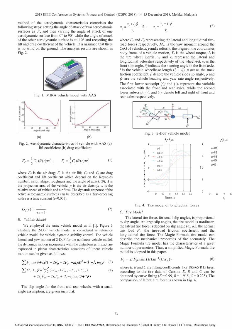
where Fy and Fx representing the lateral and longitudinal tire-road forces respectively, Mwz is the yaw moment around the CoG of vehicle, x, y and z refers to the origin of the coordinates body frame of a vehicle motion, Tb is the wheel torque, Jb is the tire wheel inertia, vy and vx represent the lateral and longitudinal velocities respectively of the wheel-set, αf is the front slip angle, δf indicate the steering angle in the front axle, l is the vehicle wheelbase length (lf + lr), μ act as the track friction coefficient, β denote the vehicle side slip angle, ψ and
are the vehicle heading and yaw rate angle respectively. The first lower subscript (·)f and (·)r represent the variable associated with the front and rear axles, while the second lower subscript (·)l and (·)r denote left and right of front and rear axles respectively.
Fig. 3. 2-DoF vehicle model
Fig. 4. Tire model of longitudinal forces
C. Tire Model The lateral tire force, for small slip angles, is proportional
to slip angle. At large slip angles, the tire model is nonlinear, the lateral tire force is depend on slip angle (αf, αr), the normal tire load Fz, the tire-road friction coefficient and the longitudinal tire force. The Magic Formula tire model can describe the mechanical properties of tire accurately. The Magic Formula tire model has the characteristics of a great number of parameters. Thus, a simplified Magic Formula tire model is adopted in this paper.
1sin ( tan ( ))y z fF E F B C (6)
where E, B and C are fitting coefficients. For 185/65 R15 tires, according to the tire data of Carsim, E, B and C can be obtained by curve fitting (E = 0.99, B = 1.915, C = 0.225). The comparison of lateral tire force is shown in Fig. 4.
-0.4 -0.2 0 0.2 0.4 0.6-4
-2
0
2
4
Fx = Fx(s, )
Slip ratio, s
Longitudin
al fo
rce, F
x, [k
N] =0
=0.12
=0.24
=0.36
=0.48
=0.6
-0.4 -0.2 0 0.20
1
2
3
4
fx=fx(sx,sy)
sykn
sx=0.06
sx=0.12
sx=0.18sx=0.24
sx=0.3
Authorized licensed use limited to: UNIVERSITY TEKNOLOGI MALAYSIA. Downloaded on December 16,2020 at 06:32:14 UTC from IEEE Xplore. Restrictions apply.

III. CONTROL ALLOCATION
The hierarchical control architecture of the proposed control strategy contains an upper and a lower controller is demonstrated in Fig. 5.
A. Upper Control The objective of the upper controller is to ensure the high
speed stability. It uses measurements from various on-board sensors, and computes the desired vehicle dynamics and desired additional yaw moment for stability control. The peak lateral acceleration must be bounded by the tire road friction coefficient μ as follows
,maxya g (7)
where g is the gravity unit and ɛ is the safety factor. In this paper, the value of ɛ is set as 0.85. The empirical relation on the upper and lower bound for the side slip angle can be described as follows [2].
1, tan (0.02 )des x desg v gdesdes gg (8)
Thus, the desired yaw rate ( des) and desired side slipangle (βdes) for the vehicle can be obtained from steering angle, vehicle speed, tire-road friction coefficient and vehicle parameters as follows [2].
21 1[ ( ) ( ( ) ) ] [ ]y r f xq y r r f f xq xx x f xq fxx x xx
mv C C J v C l C l J I mv C JI v I
1I
] [1I
]1yvy I v
(9)
2 21 [ ( ) ( ) ]zz r r f f y f f r r f f f zx
I C l C l v C l C l C l Mv
2 21 [ ( ) ( )r r f f y f f r r) ( f f f zC l M) ( ) ]) ( 2 2) () () ( f zv[ ) ] f fC lC l] f f[ ( ) ( )) () ( 2 2) () () ( f[ C lC l] f f
(10)
To make a vehicle follow the desired yaw rate and the desired side slip angle, a sliding mode controller is designed to calculate the additional yaw moment (Mz), which is required by dynamics tracking. The sliding surface is defined by
( )ref des dess ref des (ref des (((f d(11)
Differentiating (11):
( )ref des dess )desref des (ref des ((ref des(12)
As in [2], set 2 21 2ds s s sdt2s ss , and combining (3),
(4), (11) and (12), then the control law is yielded as follow
2 2
( ( ) ( )z z des ref des des f f r r
f f r rref f f f
x
M I l C l C
l C l Cl C
v
(des rdes r(des rdes (((des rdes (
ref f fref f fl Cf ffref
(13)
where η and ζ are the control parameters of sliding mode control and greater than zero.
B. Lower Controller The lower controller determines the brake pressure at each wheel and the angle of attack of the airfoils, so as to generate a net yaw moment, which is determined by the upper controller, for tracking the desired dynamic responses. A control strategy is designed for coordinating differential brake and active aerodynamic control. The control allocation technology is utilized in this study for brake pressure allocation.
The aerodynamic forces of the vehicle are proportional to the square of relative velocity of the vehicle and the airflow. Under low speed condition, the aerodynamic force/moment of the vehicle is small, and cannot achieve the purpose of the active intervene in the state of vehicle dynamics.
Fig. 5. Control scheme proposed
Fig. 6. Integrated control strategy
While the aerodynamic force/moment of the vehicle cannot be ignored under high speed condition. The coordinated control strategy for both actively controlled aerodynamic surfaces and hydraulic brake system is shown in Fig. 6. Only differential braking control is used for stability control under low speed condition (vx < 20 m/s), both differential braking control and active aerodynamic controlare used to improve stability under high speed condition (vx ≥ 20 m/s).
The controller calculate the maximum aerodynamic force of the vehicle, Fa,max, which can be provided by active aerodynamic control. When the additional yaw moment, Mz
is less than or equal to Ma,max, the moment for stability is generated by active aerodynamic control. When |Mz| is larger than |Ma,max|, both active aerodynamic surfaces are controlled to generate the maximum aerodynamic moment of the vehicle, and the differential braking control is used to compensate the yaw moment. The additional yaw moment
Authorized licensed use limited to: UNIVERSITY TEKNOLOGI MALAYSIA. Downloaded on December 16,2020 at 06:32:14 UTC from IEEE Xplore. Restrictions apply.

that need to be generated by active aerodynamic control is represented as Ma. The additional yaw moment that need to be generated by differential braking control is represented as Mh.
The objective of the active aerodynamic control module is to determine the attack angle of each air foil, so as to provide the desired aerodynamic moment Ma. The aerodynamic control modes of air foils is decided according to Ma. To avoid start/stop the active aerodynamic control system frequently, when absolute value |Ma| is too small, a control threshold Mth is set (Mth is positive). The extra longitudinal aerodynamic drag force needed to produce the desired yaw moment Ma and the desired longitudinal aerodynamic drag force Fd (θ) can be obtained as
,0, ( )ad d d d
a
MF F F F
l(14)
where la is the arm of drag force, Fd0 is the longitudinal aerodynamic drag force, when both air foils are turned off. Hence, the angle of attack of the target air foil can be determined by (1) and Fig. 2(b).
The primary objective of the control allocation module is to generate Mh, and track the desired yaw response. Another objective of this module is to minimize the braking force for energy saving. An optimal braking force distribution algorithm is adopted to achieve differential braking control under the constraint of actuators and tires. Under differential braking condition, the limitation of the longitudinal force of each wheel can be determined by the braking torque.
,max ,min,max ,min,bi bi
xi xi
T TF F
R R(15)
where Fxi,max (Fxi,min) is the maximum (minimum) braking force of each wheel, R is the radius of the wheel. A weighting factor η is used in this study. The weighted least squares problem:
min max
2 2
2 2arg min (d vu u u
U U U W BU V (16)
where Umin and Umax are decided respectively by the tire-road friction coefficient constraint and actuator constraint, which is the maximum torque range of in-wheel-motors. Wu is the diagonal weighting matrix, which shows the different of vertical load between each wheel. To minimize the allocation error, η is usually set to very large.
IV. RESULT AND DISCUSSION
The vehicle model with active aerodynamic control system was established in Matlab, which is an accurate multi-body vehicle simulator. The validity of the proposed method was evaluated through joint simulation of Matlab & Simulink.Double lane change test was conducted to investigate the effectiveness of the proposed method. A closed-loop driver model was used as steering controller for following the target path. The test was carried out at the velocity of 30 m/s, which should possibly be constant by the driver or cruise control system. The road surface is assumed to be flat and smooth. Two kinds of tire-road friction coefficient (0.85 & 0.4) are adopted. In this paper, the front wheels are drive wheels and
the rear wheels are non-drive wheels. The main parameters of the vehicle are listed in detail in [1].
The performance of the proposed integrated control method (IC) and traditional differential braking control method (DBC) are compared by simulation method. Double lane change test was carried out to compare the effects of the control methods. Tire workload usage is a key evaluation indicator, which reflects the utilization of road adhesion ability [9]. Tire workload of each wheel can be defines as
2x y
z
F F
F(17)
Figure 7 illustrates the control inputs such as yaw moment, angle of attack, and brake pressure as a function of time. It can be seen from Fig. 7(a) that Mh is less than Mz. The additional yaw moment Mz needs to be generated by differential braking control for the vehicle under DBC. However, the additional yaw moment Mh needs to be generated by differential braking control for the vehicle under IC. The difference between Mz and Mh is the additional yaw moment generated by active aerodynamic control (Ma).
The angle of attack of the airfoils is shown in Fig. 7(b). The angle of attack of the airfoils reach 90° three times for generating Ma.max. When | Mz|= Ma,max, under IC, differential braking control function will be activated. The brake pressure of each wheel under IC and DBC are illustrated in Fig. 7(c). The vehicle under IC conducted differential braking control is later than that under DBC. The peak value of brake pressure of each wheel under IC is lower than that under DBC. For example, at 2 s, the peak value of brake pressure of rear left wheel under IC is 27.97% less than that under DBC; at 5.1 s, the peak value of brake pressure of rear left wheel under IC is 20.89% less than that under DBC. The steering wheel angle is illustrated in Fig. 7(d). It indicates that there is no difference on driver’s operation between IC and DBC.
The results are shown in Fig. 8. It can be seen from Fig. 8(a) that both the IC and DBC stabilize the vehicle to pass the target path. The yaw rate under IC can better matches the desired yaw rate than that under DBC, as shown in Fig. 8(b). At large slip angles, changing the steering angle produces very little change in the yaw rate of the vehicle [2]. The vehicle under IC and DBC can follow the desired slip angle, as illustrated in Fig. 8(c). However, the slip angle under IC is relatively small. The maximum lateral accelerations are less than the peak acceleration, which is bound by the road surface, as in Fig. 8(d). It indicates that the vehicle has enough lateral stability margin. The average of the maximum lateral acceleration under IC is 5.1% less than that under DBC. The result of slip angle and lateral acceleration means that the vehicle under IC is more stable to some extent. The tire workload usage of each wheel is shown in Fig. 8(e) and table 3. The peak tire workload usages of front left wheel and frontright wheel under IC is slightly larger than that under DBC. However, the peak tire workload usages of front left wheel and front right wheel under IC is significantly smaller than that under DBC.
The comparison results of tire workload usage can be explained as follows: First, to maintain the target speed, the drive system of the vehicle will increase the power output. As shown in Fig. 2(b), the drag force of the vehicle will increase with the increase of the angle of attack of the airfoils. The drag force of the vehicle under IC is larger than that under DBC.
Authorized licensed use limited to: UNIVERSITY TEKNOLOGI MALAYSIA. Downloaded on December 16,2020 at 06:32:14 UTC from IEEE Xplore. Restrictions apply.

This means that a greater driving force is required for the vehicle under IC to overcome the aerodynamic drag force. It means that the longitudinal tire forces of the front wheels will increase as well as the tire workload usages of the front wheels.
Second, as shown in Fig. 2(a), the lift force of the vehicle will decrease when the angle of attack of the airfoils is non-zero. It indicates that the vehicle is subjected to larger downward force. According to (17), the tire workload usage will become smaller for the increase of vertical tire force. The increase of vertical tire force will expand tire adhesion limit. It means that the risk of tire force saturation will be reduced.
Third, as shown in Fig. 7(c), the vehicle under IC has a lower braking strength. For the non-drive wheels, the smaller the braking strength, the smaller longitudinal tire force.
In summary, the tire workload usage of the rear wheels of the vehicle under IC will become smaller because of the increase of the vertical tire force and the decrease of the longitudinal tire force. The tire workload usage of the front wheels of the vehicle under IC is slightly larger than that under DBC. This is due to the increase of driving force and vertical tire force and the decrease of braking force.
The control inputs are shown in Fig. 9. It can be seen from Fig. 9(a) that Mh is obviously less than Mz. This means that most of the additional yaw moment required for stability control is generated by active aerodynamic control on the wet road. Most of the time the angle of attack of airfoils did not reach the maximum, as is shown in Fig. 9(b). The brake pressure of each wheel under IC and DBC are illustrated in Fig. 9(c).
The peak value of brake pressure of each wheel under IC is obviously less than that under DBC. By compared with the control inputs on the dry road, the reason for the control inputs become smaller is that the desired yaw rate and desired side slip angle for the vehicle are bounded by the tire-road friction coefficient. The steering wheel angle is illustrated in Fig. 9(d).
It indicates that there is no difference on driver’s operation between IC and DBC. Figure 10 shows the simulation results on the wet road. Similar control performance can be obtained as that on the dry road.
(a)
(b)
Fig. 7. Control inputs (a) yaw moment (b) angle of attack
(a)
(b)
(c) Fig. 8. Control results (a) path (b) yaw rate (c) tire workload
usage
(a)
(b) Fig. 9. Control inputs (a) yaw moment (b) angle of attack
(a)
Authorized licensed use limited to: UNIVERSITY TEKNOLOGI MALAYSIA. Downloaded on December 16,2020 at 06:32:14 UTC from IEEE Xplore. Restrictions apply.

(b)
(c)
Fig. 10. Performance results (a) path (b) yaw rate (c) tire workload usage
V. CONCLUSION
This paper presents a novel integrated control method to improve vehicle driving performance under high speed conditions. It comprises of an upper layer and a lower layer controller. A sliding mode control approach is adopted to determine the desired yaw moment. A control strategy is designed in the lower controller for coordinating active aerodynamic control and differential braking control.
In this paper, the feasibility of active aerodynamic control for vehicle stability control is explore in theory. The proposed method is verified in software simulation without experimental. To this end, the proposed method will implemented in hardware-in-loop platform and a prototype vehicle in the future.
REFERENCE
[1] F. Yakub, P. Muhammad, H.T. Toh, M.S.A. Talip and Y.Mori, “Explicit controller of a single truck stability and rollover mitigation”, J. of Mechanical Science and Tech., vol. 32, no. 9, pp. 4373-4381, 2018.[2] R., Rajamani, “Electronic Stability Control”. In Vehicle Dynamics and Control, Springer US: Boston, MA, 2012; pp 201-240.[3] S. J. Zhu, and Y. P. He, “A driver-adaptive stability control strategy for sport utility vehicles”, Vehicle System Dynamics, vol. 55, no. 8, pp. 1206-1240, 2017. [4] M. Goharimanesh, and A. A. Akbari, “Improving lateral dynamic of vehicle using direct yaw moment controller by differential brake torques based on quantitative feedback theory”, Scientia Iranica, vol. 24, no 2, pp. 662-672, 2017. [5] F. Yakub, A. Abu, and Y. Mori, “Enhancing the yaw stability and the manoeuvrability of a heavy vehicle in difficult scenarios by an emergency threat avoidance maneuver”, J. of Automobile Engineering, vol. 31, no. 5, pp. 615-637, 2017.
[6] J. Song, “Active Front Wheel Steering Model andController for Integrated Dynamics Control Systems”, Int. J.of Automotive Technology, vol. 17, no. 2, pp. 265-272, 2016. [7] C. Y. Wang, W. Z. Zhao, Z. J. Xu, and G. Zhou, “Path planning and stability control of collision avoidance system based on active front steering”, Science China-Technological Sciences, vol. 60, no. 8, pp. 1231-1243, 2017. [8] X. J. Wu, B. Zhou, G. L. Wen, L. F. Long, and Q. J. Cui, “Intervention criterion and control research for active front steering with consideration of road adhesion”, Vehicle System Dynamics, vol. 56, no. 4, pp. 553-578, 2018. [9] B. Li, A. Goodarzi, A. Khajepour, S. K. Chen, and B. Litkouhi, “An optimal torque distribution control strategy for four-independent wheel drive electric vehicles”, Vehicle System Dynamics, vol. 53, no. 8, pp. 1172-1189, 2015. [10] A. Nahidi, A. Kasaiezadeh, S. Khosravani, A. Khajepour, S. K. Chen, and B. Litkouhi, “Modular integrated longitudinal and lateral vehicle stability control for electric vehicles”, Mechatronics, vol. 44, pp. 60-70, 2017. [11] A. Goodarzi, and M. Mohammadi, “Stability enhancement and fuel economy of the 4-wheel-drive hybrid electric vehicles by optimal tyre force distribution”, Vehicle System Dynamics, vol. 52, no. 4, pp. 539-561, 2014. [12] M. Mirzaei, and H. Mirzaeinejad, “Fuzzy Scheduled Optimal Control of Integrated Vehicle Braking and Steering Systems”, IEEE-ASME Transactions on Mechatronics, vol. 22, no. 5, pp. 2369-2379, 2017. [13] B. T. Ren, H. Chen, H. Y. Zhao, and L. Yuan, “MPC-based yaw stability control in in-wheel-motored EV via active front steering and motor torque distribution”, Mechatronics, vol. 38, pp. 103-114, 2016. [14] M. Jalali, S. Khosravani, A. Khajepour, S. K. Chen, and B. Litkouhi, “Model predictive control of vehicle stability using coordinated active steering and differential brakes”, Mechatronics, vol.48, pp. 30-41, 2017. [15] M. Corno, S. Bottelli, M. Tanelli, C. Spelta, and S. M Savaresi, “Active control of aerodynamic surfaces for ride control in sport vehicles”, In 19th IFAC World Congress on Int. Federation of Automatic Control, IFAC 2014, Cape Town, South Africa, pp 7553-7558.[16] A. R. Savkoor, and C. T. Chou, “Application of aerodynamic actuators to improve vehicle handling”, Vehicle System Dynamics, vol. 32, no. 4-5, pp. 345-374, 1999. [17] M. Corno, S. Bottelli, M. Tanelli, G. Panzani, C. Spelta, M. Tanelli, and S. M. Savaresi, “Performance Assessment of Active Aerodynamic Surfaces for Comfort and Handling Optimization in Sport Cars”, IEEE Trans. on Control Systems Tech., vol. 24, no.1, pp. 189-199, 2016. [18] G. Lodewijks, A. J. G. Nuttall, C. Mazzali, R. Mecheroni, and A. R. Savkoor, “Ride comfort enhancement considering car body aerodynamics using actively controlled spoilers”, Swets en Zeitlinger B.V. vol. 41, pp. 162-171, 2004.
Authorized licensed use limited to: UNIVERSITY TEKNOLOGI MALAYSIA. Downloaded on December 16,2020 at 06:32:14 UTC from IEEE Xplore. Restrictions apply.