verification of distributed real-time computer network architecture associated with off-the-shelf...
TRANSCRIPT

1206 IEEE TRANSACTIONS ON POWER DELIVERY, VOL. 24, NO. 3, JULY 2009
Verification of Distributed Real-Time ComputerNetwork Architecture Associated With Off-The-Shelf
and Dedicated TechnologiesYoshizumi Serizawa, Senior Member, IEEE, Tatsuji Tanaka, Member, IEEE, Hiroyuki Yusa, Yoshiyuki Koda,Goro Yamashita, Masaya Miyabe, Shigeki Katayama, Takehiko Tsuchiya, and Kazuya Omata, Member, IEEE
Abstract—This paper introduces an architecture for computercommunications applied to the operation and maintenance ofpower systems, the distributed real-time computer network ar-chitecture (DRNA). The architecture consists of four functionalentities, namely, application programs associated with informa-tion models, an adaptation function, a transport function, andnetwork- and security-management functions to achieve seamless,real-time, adaptive, and secure information exchange betweendistributed power system control devices. DRNA uses off-the-shelfand standardized technologies along with dedicated ones. Throughcareful application of the technology, an experimental setup of adistributed cooperative voltage-control network was constructedin a power system simulator to verify the architectural concept.The implemented technologies include mobile agents, middle-ware for prioritized and redundant communication schemes,label-switched and Ethernet-based transport networks, and asecure virtual private network. The experiment demonstrated theeffectiveness of DRNA.
Index Terms—Architecture, computer network security, coop-erative systems, Internet, object-oriented programming, powersystem communication, protocols, supervisory control anddata-acquisition (SCADA) systems.
I. INTRODUCTION
R ELIABILITY and security are of the utmost importancefor control and communication systems used in the
operation and maintenance of power systems. In addition,reductions in the cost of system construction, operation, andmaintenance, and increased interconnectivity among controldevices, are objectives that have yet to be properly realized.Electric power companies and control device vendors are now
Manuscript received October 09, 2006; revised February 03, 2009. Currentversion published June 24, 2009. Paper no. TPWRD-00622-2006.
Y. Serizawa and H. Yusa are with the Central Research Institute of Elec-tric Power Industry (CRIEPI), Komae-shi, Tokyo 201-8511, Japan (e-mail:[email protected]; [email protected]).
T. Tanaka, S. Katayama, T. Tsuchiya, and K. Omata are with the ToshibaCorp., Fuchu Complex—Power Systems Protection and Control, Tokyo183-8511, Japan (e-mail: [email protected]; [email protected]@toshiba.co.jp; toshiba.co.jp; [email protected]).
Y. Koda is with the Tohoku Electric Power Co. Inc., Sendai 980-8550, Japan(e-mail: [email protected]).
G. Yamashita is with the Shikoku Electric Power Co., Takamatsu 760-8573,Japan (e-mail: [email protected]).
M. Miyabe is with the Tokyo Electric Power Co., Chiyada-ku, Tokyo 100-8560, Japan (e-mail: [email protected]).
Color versions of one or more of the figures in this paper are available onlineat http://ieeexplore.ieee.org.
Digital Object Identifier 10.1109/TPWRD.2009.2022668
employing off-the-shelf and standardized techniques. Powersystem communications networks are also being integrated intoInternet-Protocol (IP)-based networks [1]–[4]. For example,an intelligent electronic device (IED) is a term that describesmicroprocessor-based controllers of power system equipment,such as circuit breakers (CBs) and transformers, associated withcommunication capabilities. IEDs receive data from sensorsand power equipment, and can issue control commands, suchas tripping CBs. IEDs with Ethernet communication interfacesare being increasingly introduced to replace conventionalcontrol devices and are becoming internationally standardized[5] and used [6]. Further, new technologies, such as mobileagent techniques [7], [8] and Web-based server functions [9],are now being considered for installation. We should see thesenew control devices and techniques fulfilling their potential ina new generation of power system operation and maintenance.Although these techniques are advantageous in terms of inter-connectivity and cost cutting, other aspects, such as real-timefeatures, reliability, and security required for power systemcontrol also need to be ensured.
Important work in the field of power system control andcommunication is also being conducted by various organi-zations, including IEC TC57 (Power Systems Managementand Associated Information Exchange) [10], the IntelliGridConsortium [11], and the GridWise Alliance [12]. These groupsaim at de-facto or industry standardization, multivendor andcommercial off-the-shelf (COTS) equipment deployment, andcost-effective guarantees of reliability, security, and quality ofservice (QoS), where QoS also refers to the ability to providedifferent priorities to different applications, users, or data flows,or to guarantee a certain level of performance to a data flow.IEC TC57, for example, has proposed a reference model fora future power-management system architecture comprisingcommunication protocols, information models, and securitymeasures [13]. The IntelliGrid Consortium shows a roadmapto a next-generation power system consisting of automatedtransmission and distribution systems that support the efficientand reliable delivery and supply of power [14]. The IntelliGridarchitecture is a set of open, standards-based technologies forintegrating power and communications systems to improvethe reliability, quality, and security. These endeavors are verybroad ranging, moving steadily forward, and still in progress.
The authors have also been conducting a similar project fora computer communication architecture applied to the opera-tion and maintenance of power systems, and have proposed the
0885-8977/$25.00 © 2009 IEEE

SERIZAWA et al.: VERIFICATION OF DISTRIBUTED REAL-TIME COMPUTER NETWORK ARCHITECTURE 1207
TABLE IAPPLICATIONS IN DRNA-BASED NETWORKS
distributed real-time computer network architecture (DRNA)[15], [16]. The concept of DRNA is to ensure real-time, reli-able, and secure information exchange in an IP-based network.When comparing DRNA with the IntelliGrid approach, for ex-ample, the former emphasizes real-time features and reliability,while the latter seems to achieve greater interoperability or inter-system connectivity between power industry businesses. Irre-spective of the approach adopted, it is necessary at particulardevelopment stages to preliminarily implement and examine theapplicable technologies, verifying first their functional appli-cability and then their performance (real-time operation, reli-ability, etc.).
This study verifies the functional applicability of DRNA andsome aspects of its performance in a small-scale system. Itfirst identifies information and communication technology re-quirements for power system operation and maintenance. Next,it describes the coordinated function assignments of DRNA.DRNA uses off-the-shelf and dedicated technologies. Finally,results of an experiment using a power system simulator arepresented to verify the effectiveness of the DRNA concept.The experimental setup consists of four elements. The first isa distributed cooperative voltage and reactive power control(VQC) program implemented in software components calledmobile agents. The second is another software componentcalled middleware, which is used for prioritized and redun-dant communication schemes associated with the IP-basedcommunications network, the third element. The third elementtechnology includes multiprotocol label switching (MPLS),a mechanism to carry many different kinds of informationtraffic using labels attached to information packets [17], andthe Ethernet. The fourth is security technologies, such as anIP-based virtual private network (IP-VPN), used to separatetraffic from different applications over an underlying networkwith strong security features.
II. POWER SYSTEM APPLICATIONS AND
FUNCTIONAL REQUIREMENTS
A. Applications Supported by DRNA
DRNA provides information exchange for power systemoperations, such as supervisory control and a data-acquisi-
tion (SCADA)/energy-management system (EMS) and facilitymaintenance, mainly focusing on real-time and reliable commu-nications relevant to distributed control devices, as summarizedin Table I.
For power system operation, supervisory control and data-acquisition (SCADA) monitoring data (telemetry and supervi-sion) and telecontrol data are transmitted between control cen-ters and unmanned, smaller power stations, or substations. EMScomputers in a load dispatching center communicate for pur-poses, such as load frequency control to/from large power sta-tions and substations. Intercontrol center communication be-tween manned sites, such as load dispatching centers and controlcenters, includes information exchange of area-specific powersystem data, meteorological data, and load/generation records.Recently, constructed substations are equipped with Ethernet-based substation automation systems. In distribution automa-tion or management systems, supervisory control data are trans-mitted between distribution control centers and field control ter-minals via distribution substations.
Data transmission for power system protection, such asfault clearance and emergency control, is beyond the scope ofDRNA because the proprietary and vendor-specific techniquesused until now have meant that off-the-shelf technologies aredifficult to apply. Ethernet-based intersubstation relay commu-nications may be applied in the near future.
Facility maintenance within the scope of DRNA includes theexchange of power system facility-management data, such as fa-cility health check, substation video surveillance, and telecom-munication facility management.
B. Functional Requirements
Two types of real-time systems exist: 1) deterministic (hard)and 2) nondeterministic (soft) [18]. Power system operation ap-plications shown in Table I are basically deterministic; for ex-ample, most power companies have a latency requirement of 1s for their SCADA network because of the time criticality ofpower equipment operations. Facility maintenance applicationsare mostly nondeterministic; latency of somewhere around 10 or20 s may be acceptable for maintenance personnel. The shorterthe latency is, the more preferable it is for maintenance workefficiency.

1208 IEEE TRANSACTIONS ON POWER DELIVERY, VOL. 24, NO. 3, JULY 2009
TABLE IIREQUIREMENTS FOR DRNA-BASED NETWORKS
SCADA/EMS networks for dependable and secure powerdelivery mainly require deterministic real-time features, re-liability (availability or redundancy), and security. Majorsolutions to date for these networks have been dedicated, pri-vate, self-owned/operated for each application, and/or isolatedfrom external networks. As nondeterministic real-time systems,on the other hand, facility maintenance applications usingvarious types of sensors and actuators require more versatility,efficiency, and interconnectivity among devices and operationsystems, and openness for multivendor use and cost efficiency,while they are integrated into the same real-time network at alower priority.
Considering the characteristics of the aforementioned appli-cations and networks, the requirements for DRNA are summa-rized in Table II. Communications for power system operationshould be secure, reliable, and in deterministic real time (as-suming a deadline, response time, or latency of 1 s). Communi-cations for facility maintenance should be flexible and orientedtoward off-the-shelf devices, because various types of new de-vices are expected to emerge that also prefer nondeterministicreal-time operation and reliability. In brief, the first three cri-teria: real time (deterministic), reliability, and security, are strictrequirements for power system operation networks, while thelatter two are important for facility maintenance networks.
III. FUNCTION AND TECHNOLOGY ASSIGNMENTS OF DRNA
A. Overview
In consideration of the existing technologies and varying re-quirements, the strategies for developing DRNA are as follows:
1) Existing off-the-shelf and standardized technologies, suchas IP, security measures, and IEC standards are to be prop-erly selected and applied, while implementation and con-figuration policies depend on each user.
2) If some of these existing technologies are insufficient, nec-essary technologies will be modified or newly developed.
To meet the requirements of power system managementshown in Table II, the information-exchange architecture, orDRNA, can be simply defined as shown in Fig. 1. DRNA
Fig. 1. Functional structure of DRNA.
consists of four functional entities: 1) application programswith power equipment/system information models, 2) an adap-tation function, 3) a transport function, and 4) network- andsecurity-management functions.
Information models are software definitions of managed ob-jects, such as power equipment and system configurations, il-lustrating their attributes and operations as well as the physicaland logical relationships between them. Developing informa-tion models in an object-oriented manner are now a commonpractice. The models are primarily IEC standard based [19],[20].
The transport function provides accurate and real-time infor-mation transfer between any given pair of sites or control de-vices. De-facto standard IP technologies are promising in termsof integrating power system control communications [4], whileconventional digital transmission technologies [21] using fixed-length and fixed-interval frames with link-by-link channel seg-regation may be sufficiently accurate and secure in some cases.This component of DRNA uses primarily off-the-shelf IP-basedcommunications equipment.
The adaptation function located between the application pro-gram and the transport function provides autonomous adapt-ability to changes in power system control and communicationnetworks. It also ensures real-time and reliable interobject com-munication for applications in cooperation with the transportfunction network. Measures for QoS-guaranteed and reliablecommunication over IP networks can be achieved by dedicatedmiddleware. Middleware is generally computer software thatconnects software components or applications, allowing themto exchange data. In some cases, it operates between the op-erating system (OS) and user application software to run theprocessing and procedures that the application requests of theoperating system, to lessen the effect of differences in OSs andhardware and ease the development of application software thatruns on various computer and communication systems.
The network- and security-management functions provideautomatic supervision, diagnosis, and testing of traffic, QoS,equipment, and network performance as well as secure barriersagainst unwanted and intentional attacks on power systemoperations.
Each entity will be described in greater detail.

SERIZAWA et al.: VERIFICATION OF DISTRIBUTED REAL-TIME COMPUTER NETWORK ARCHITECTURE 1209
TABLE IIIFUNCTIONAL ENTITIES OF ADAPTATION FUNCTION MIDDLEWARE
B. Object-Oriented Information Models and Power SystemApplications
Information models are being developed by IEC TC57 inIEC standards 61970 (Energy Management System-ApplicationProgram Interface; EMS-API) to form the basis of the commoninformation model (CIM) [19] and 61850 (substation commu-nication) as logical nodes and devices [20] aiming at open andmultivendor deployment. Domestic concerns as well as interna-tional consistency should be taken into account.
The information models can be improved by consideringglobal or wide-area information for load dispatching, systemoperation, and switching in control centers, and local informa-tion for power equipment in substations and power stations.Since IEC TC57 is now working on this model coordination,the authors proposed a preliminary approach to coordinate bothmodels for practical implementation [16], [22]. In DRNA, IEC61970 and IEC 61850 are adopted and modified by using aJava class library suitable for object-oriented implementation,where local information models are tentatively aggregated intoglobal models.
Since DRNA deals with various applications, as shown inTable I, off-the-shelf technology implementations, such as aninformation exchange based on Extensible Markup Language(XML) [23] and Web-based browsing may be effective. Mo-bile agents [24] can be defined as autonomous and intelligentprograms that move through a network, searching for and inter-acting with services on the user’s behalf. They may be usefultools for adaptive and autonomous decentralized schemes ofinformation delivery, collection, and processing when appliedas 1) applications that employ distributed processing wheremany processing points are not predetermined and 2) light-weight applications, such as DAQ or setting. However, they arenot suited for time-critical and resource-intensive applications.Mobile agents show promise for applications in distributedoperation and facility maintenance, including status data col-lection (supervision), fault/failure analysis, relay setting, anddata retrieval from distributed databases. These applicationsmay be specified in more detail in the near future. Due to recentimprovements in technology and computational performance,mobile agents are becoming applicable to also deterministicreal-time systems.
C. Adaptation Function
The adaptation function employs ordinary information-ex-change protocols, such as object message communication using
Fig. 2. System operation and facility maintenance networks are separated fromeach other physically or by the VPN mechanism and separated from the corpo-rate business network.
remote procedure call (RPC) or remote method invocation(RMI), which allows a computer program to cause a subrou-tine or procedure to execute in another computer on a sharednetwork without the programmer explicitly coding the detailsfor this remote interaction, file transfer (FTP) [25], and hy-pertext communication (HTTP) [26]. This provides flexibilityand adaptability for power system management. Proprietaryor dedicated functional entities are also created in the formof middleware [27] in this function layer, as summarized inTable III. For achieving real-time features, priority controlof packet transmission is implemented. The type-of-service(ToS) [28] setting entity operates in cooperation with QoScontrol in IP-based transport networks, where the ToS bytein the IP packet header is used to indicate the importance ofthe packet and requests for low delay, high throughput, and/orhigh reliability. Other priority controls operate in isolation.For achieving reliable transmission, redundant transmissioncontrols are implemented to avoid missing information due tocommunication errors. Each entity can be used in isolation orin combination with others.
To use network resources efficiently, information caching andpacket flow control (shaping/policing) are also performed bythe middleware. This is similar to active network operations, inwhich routers conduct primitive communication and informa-tion processing. For utilizing mobile-agent-based applications,an agent platform specialized for security and dependability forpower system use is installed in this function.
The application programming interface (API) is, in general,a set of functions, procedures, methods, classes, or protocolsthat an operating system, library, or service (adaptation func-tion middleware in our case) provides to support requests made

1210 IEEE TRANSACTIONS ON POWER DELIVERY, VOL. 24, NO. 3, JULY 2009
TABLE IVCURRENT SOLUTIONS FOR TRANSPORT NETWORK
Fig. 3. Implementation of DRNA for power system monitoring and control.
by application programs. An API is also defined for the middle-ware.
D. Transport Function
IP-based, real-time, and wide-area networks for inte-grating power system communications are generally eitherMPLS router-based VPN or Ethernet-based wide-area virtuallocal-area network (VLAN), allowing for control devices tobe grouped together even if they are not located on the samenetwork switch, with appropriate QoS control and prioritizedtransmission techniques [29]. A complete double redundantconfiguration for nodes and links with detouring based onopen shortest path first (OSPF) [30] is established if necessary.Table IV shows current solutions for a transport network. Afeasible configuration for a larger IP network may be a com-bination of trunk MPLS networks and local Ethernet networks[29].
E. Network- and Security-Management Functions
The network-management function can be achieved by off-the-shelf techniques, such as the simple network-managementprotocol (SNMP) [31] and administered by network-manage-ment servers. Supervisory and control information for the net-work management is exchanged in an IP network separate fromor shared with the supervised network.
Security functions spread from the lower to the upper commu-nication protocol layers. Network separation is a fundamentalsecurity practice for power companies. For example, operationand maintenance networks are separated from each other bya VPN or VLAN mechanism and are separated from the cor-porate business network, as shown in Fig. 2. The maintenance
network may also operate as a data historian and demilitarizedzone (DMZ), a physical or logical subnetwork that contains andexposes external services to the corporate business network,adding an additional layer of security to the system operationnetwork. A unidirectional gateway, referred to as a data diode,is indispensable. In-depth security, if needed, can be provided byimplementing intrusion detection systems, access control, oper-ator authentication, and/or message authentication in the appli-cation layer; port-segregated encryption, such as transport-layersecurity (TLS) [32] in the transport layer, and/or authenticationand encryption of each IP packet of the data stream by InternetProtocol security (IPsec) [33].
F. Interrelation of Functional Entities
The implementation and interrelationship of DRNA func-tional entities are summarized in Table V, including well-knownmethodologies. Fig. 3 depicts an illustrative sample implemen-tation of DRNA for power system monitoring and control.
IV. IMPLEMENTATION AND VERIFICATION OF DRNA
A. Configuration
Since DRNA is mainly intended for deterministic real-timeapplications in power system operation, an experimental VQCsystem was constructed as an application. Since the control al-gorithm requires, at most, a 1-s interval for monitoring and con-trol, not a severely deterministic real-time feature, all of its pro-posed functions can be combined into one system and exam-ined in terms of their cooperation and consistency. This processwould verify our architecture concept and indicate measuresfor improving it immediately if necessary. A Java-based systemwas constructed for the mobile agent application, information
SERIZAWA et al.: VERIFICATION OF DISTRIBUTED REAL-TIME COMPUTER NETWORK ARCHITECTURE 1211
TABLE VCATEGORIZED CONTENTS OF FUNCTIONAL ENTITIES
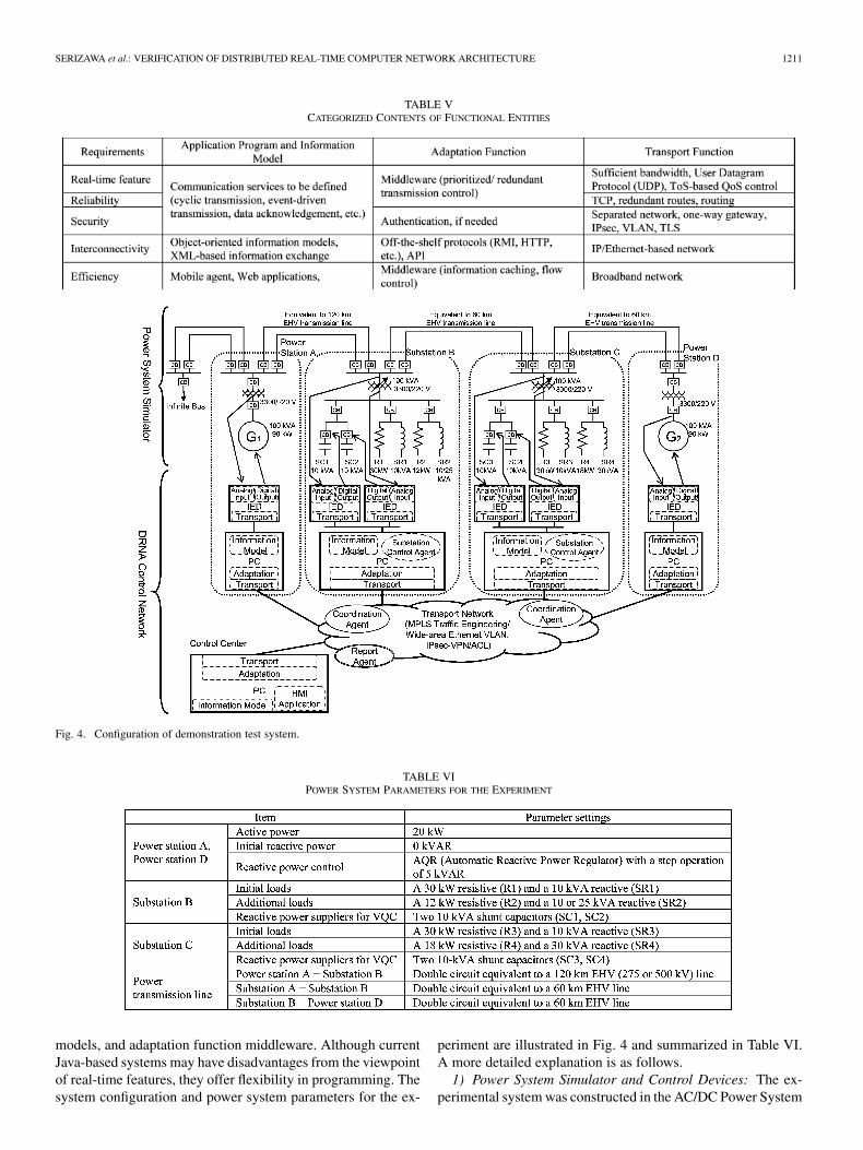
Fig. 4. Configuration of demonstration test system.
TABLE VIPOWER SYSTEM PARAMETERS FOR THE EXPERIMENT
models, and adaptation function middleware. Although currentJava-based systems may have disadvantages from the viewpointof real-time features, they offer flexibility in programming. Thesystem configuration and power system parameters for the ex-
periment are illustrated in Fig. 4 and summarized in Table VI.A more detailed explanation is as follows.
1) Power System Simulator and Control Devices: The ex-perimental system was constructed in the AC/DC Power System

1212 IEEE TRANSACTIONS ON POWER DELIVERY, VOL. 24, NO. 3, JULY 2009
TABLE VIIROLES OF AGENTS
Fig. 5. Typical local VQC algorithm.
Simulator of the Central Research Institute of the Electric PowerIndustry. The simulator consists of scaled-down power genera-tors, transmission lines, and other power apparatus operating ata voltage of 3.3 kV. A 500/220-kV (EHV) power transmissionnetwork was simulated for use in the experiment. Control de-vices were Linux-based PCs (1 GHz, 128 MB) and Java-basedIEDs, or network computing terminals (NCTs) [8], while the in-terfaces to the power equipment were operated by the real-timeOS of the NCT.
2) Applications and Information Models: Based on a typicallocal VQC algorithm, distributed cooperative VQC programs(where local VQCs performing in each substation operate co-operatively with other substations) were implemented in mobileagents operating in an autonomous decentralized manner [34].The local VQC algorithm is illustrated in Fig. 5; primary andsecondary voltages are monitored and controlled by turningthe power transformer tap up or down, or by turning the shuntcapacitor or reactor on or off for the target and deadband volt-ages. In our experiment, only shunt capacitors are controlled,because of the limitations of the control devices and powersystem equipment. The agents installed are the substationcontrol agent (SCA), coordination agent (CA), and report agent(RA), the roles of which are summarized in Table VII. TheSCA is stationed at a substation for controlling the local voltageas explained before, while the CA, bearing SCA operationstatus information and requests, moves among stations tocoordinate supporting operations, such as soliciting assistance
from neighboring stations when local control capacity is in-sufficient. For example, a voltage increase is requested fromneighboring substations when a substation’s own voltage dropsbelow the lower limit. The substation that receives the requestfor help performs the requested control action only when itcan afford to help the other substation. To prevent hunting,cooperative controls are performed so that control actionsin the opposite direction of the requested control action willnot be carried out in other substations simultaneously. Otherapplications, such as monitoring and reporting on status changeevents for the control center, were implemented as the RA. IEC61850/61970-based information models were employed forinformation exchange. Extra power equipment models for thepower station were created. Those information models wereinstalled in PCs. Station PCs issue control commands to andreceive power equipment status information from NCTs. Allof the communication channels among control devices (PCsand IEDs) were constructed by means of Java RMI API, whichis a Java application programming interface for performingthe object equivalent of remote procedure calls, as shown inTable VIII.
3) Adaptation Function Middleware: Entities of ToS setting,transmitter/receiver priority controls, and reliable transmissioncontrol for a double-redundant route with second arrival discardwere implemented [27]. An off-the-shelf mobile agent platform,mobile agent platform (MAP) [8], was adopted for the experi-ment.
4) Transport Function: Double-redundant route transmis-sion on an MPLS network and route switching on a wide-areaEthernet network with a link bandwidth of 100 Mb/s wereapplied, as shown in Fig. 6. Four MPLS routers (CISCO7200VXR) formed a quasimeshed redundant transport networkwith two separate paths explicitly constructed for each com-munication channel. When failure occurs in the network, theaffected path is switched to a backup path by a link protectionscheme.
The Ethernet-based network was constructed by using tenswitches (Cisco Catalyst 3550–12T and Catalyst 2950T-24),two of which were installed in each station, forming two re-dundant VLANs with a multiple Spanning Tree Protocol (STP)[35], ensuring a loop-free topology for any bridged LAN, andallowing the inclusion of spare (redundant) links to provide au-tomatic backup paths if an active link fails.
The functional measures for redundant communication,failure restoration, QoS, and security assurance implementedin the two transport networks are summarized in Table IX.

SERIZAWA et al.: VERIFICATION OF DISTRIBUTED REAL-TIME COMPUTER NETWORK ARCHITECTURE 1213
TABLE VIIITRANSMITTED INFORMATION BY MEANS OF JAVA RMI
Fig. 6. Transport networks implemented. (a) MPLS based. (b) Ethernet based.
For QoS assurance, many scheduling algorithms allow mul-tiple packet flows to share link capacity when communicationequipment forwards packets; priority-queuing (PQ) sched-uling that always assigns the prioritized packet flow first,round-robin (RR) scheduling that assigns equally and in order,and fair-queuing (FQ) scheduling that assigns every packet flowfairly, taking into account data-packet sizes to ensure each flow
TABLE IXFUNCTIONAL MEASURES IMPLEMENTED IN THE TRANSPORT NETWORKS
is given an equal opportunity to transmit an equal amount ofdata. Vendor-specific QoS schemes slightly modified from theaforementioned generic schemes, such as CBWFQ and WRR,were implemented as shown in Table IX. For the securitymeasures in the transport network, an access control list (ACL)that inhibits communication with devices that do not haveregistered IP addresses was implemented in the communicationequipment.
5) Security Measures: Due to the limited processing capa-bility of the IEDs and PCs, only IPsec-VPN for encrypted inter-substation communications was implemented in addition to theACL, as shown in Table IX.
B. Result of Reliable Communication on the TransportNetwork Cooperating With Adaptation Function Middleware
Initially, propagation delays of the transport network weremeasured for cascades of three or four pieces of communica-tion equipment. The results shown in Table X indicate that thepropagation delays are not crucial for our application.
After a link or equipment failure, the MPLS router networkaccomplished path switching within a few milliseconds to onesecond by means of its link protection scheme. In the Ethernet-based network, multiple STP operation successfully achievedswitching without or 0.2- to 1-s disruption by reconfiguring a

1214 IEEE TRANSACTIONS ON POWER DELIVERY, VOL. 24, NO. 3, JULY 2009
TABLE XPROPAGATION DELAYS OF CASCADED MPLS ROUTERS AND ETHERNET
SWITCHES MEASURED WITH FIXED 5-Mb/s TRAFFIC AND VARIABLE
PACKET LENGTHS (64, 128, 256, 512, 1024 B)
spanning tree that detoured the faulty link or node. The down-time due to these reconfigurations did not affect the perfor-mance of the application, owing to their double-redundant con-figurations. No packet transmission errors were observed. Whenenough bandwidths were obtained, such as more than twice therequired bit rate, congestion and the errors resulting from it didnot occur.
When applying the adaptation function middleware toachieve second-arrival discard for redundant transmission, bothnetworks were configured so that complete double-redundantroutes were realized in which no overlapped route occurredat any repeater node or link. Therefore, it appeared that nodisruption of communications in the VQC application layeroccurred even in the case of a single failure of nodes or links.
C. Result of QoS/Real-Time Feature Assurance by AdaptiveFunction Middleware
To ensure real-time performance, the middleware providesthe ToS field parameter setting upon request by applicationand prioritized processing at the transmitter and receiver.These functions were examined as follows. First, three typesof packets were created with different bit rates and priorities;low bit rate/high priority with redundant transmissions fortelemetry/telecontrol, low-bit rate/medium priority for facilitymaintenance data, and high bit rate/low priority for remotevideo surveillance. Then, they were transmitted in the samenetwork. The measured results are shown in Fig. 7. With lightor no background traffic load, the low-priority or best-efforttransmission was the fastest because of its light overhead pro-cessing, while the medium-priority and high-priority/redundanttransmissions suffered longer processing time. With heavytraffic load (almost 100% of the link capacity), however, thehigher-priority transmissions showed smaller latencies than thelow-priority transmission, of which QoS was not guaranteed,and when a link failure occurred, only the redundant transmis-sion survived. The result indicates that although the additionalcommunication latency or overhead due to the middlewareis negligible, prioritized transmissions by the middleware areeffective for a deterministic and nondeterministic real-timecomposite system. The middleware still needs improvements toachieve better performance for the high-priority and redundanttransmission under normal and heavy traffic conditions.
D. Result of Security Measures
In accordance with the security policy, the power system op-eration and maintenance networks were separately constructedin each VPN. Their ACLs were set individually for the routersand switches so that only IP addresses for the VQC applica-tion were valid in the virtual network, while other devices with
Fig. 7. Prioritized transmission by adaptation function middleware.
different IP addresses could not communicate with them. TheVQC communication was encrypted in one route with firewalls(IPsec-VPN). In the MPLS network, traffic engineering wassuccessfully applied to separate the two routes with encryption.There was no significant latency increase due to the encryptionfor the VQC operation—a few milliseconds at most.
E. Overall Operations of Distributed Cooperative VQC
With the target voltage set as 100%, 14 cases were examinedwith various parameter combinations in terms of load change,VQC operation dead bands, power equipment malfunction (e.g.,CB failure at a shunt capacitor), and inclusion or exclusion of aCA, as shown in Table XI. Fig. 8 depicts sample performancesobtained from these measurements; even in the case of an in-operable shunt capacitor, the distributed cooperative VQC, sup-ported by a CA, operated appropriately, compared with a simplelocal VQC, which resulted in failure to recover voltages. Inevery case, proper or expected operations in accordance withthe design were confirmed. Reactive power supply in substa-tions and reactive power generator taps in power stations wereproperly controlled by the local and coordination agents.
Information models were implemented so that a system-widepower system topology and measurement values of each deviceare available in the control center computer, and substation com-puters have objects modeled on power equipment in their fields.No problems were identified in the interoperation of the existingmobile agent platform, MAP, and the adaptation function mid-dleware.
Table XI summarizes the temporal characteristics of thesystem, and shows that the real-time operation is accomplishedon the order of 1 s so our control network would be comparableto a conventional system, while achieving new features, suchas decentralization and flexibility.
V. CONCLUSION
When applying state-of-the-art information and communi-cation technologies for power system operation and mainte-nance, a top priority is to ensure real-time features, reliability,and security, as in existing proprietary or dedicated networks.In this paper, based on technology requirements and assess-ments with regard to ensuring QoS, reliability, and security with

SERIZAWA et al.: VERIFICATION OF DISTRIBUTED REAL-TIME COMPUTER NETWORK ARCHITECTURE 1215
Fig. 8. Performance of VQC operation (a) with and (b) without the coordina-tion agent in the case of faulty (inoperable) SC1 at Substation B.
open (off-the-shelf or standardized) technologies, the authorsproposed a functional architecture that consists of three-layeredfunctions with newly developed middleware. This architectureprovides seamless, real-time, adaptive, and secure connectionsbetween distributed control devices. Under experimental con-ditions, the architecture was applied to a distributed coopera-tive VQC network, where every function operated properly even
TABLE XICOMBINATIONS OF OVERALL VQC EXPERIMENT PARAMETERS
TABLE XIITEMPORAL CHARACTERISTICS OF THE EXPERIMENTAL SYSTEM
in the case of communication network failures, congestion, andpower equipment malfunctions.
The results suggest the following capabilities: Off-the-shelfand standardized technologies, such as IP, VLAN, security mea-sures, mobile agents, and IEC information models provide suf-ficient flexibility and ease of network construction. Dedicatedtechnologies, such as middleware developed for ensuring reli-ability and QoS of communication, can be applied to supple-ment or enhance the open technologies in order to meet indi-vidual industry needs. Specifically, cooperative distributed ap-plications and information models are effective, and intercon-nectivity with control devices is available by using open tech-nologies. An adaptation function, however, may be needed formission-critical information exchange when using off-the-shelftechnologies in the power system arena. As an architecture forflexible and expandable systems, web services, defined by W3Cas “a software system designed to support interoperable ma-chine-to-machine interaction over a network” [36], may be acompeting technology in the future. However, while a web ser-vices system, usually XML-based, assigns various services atfixed locations, DRNA can implement mobile and autonomouselements in a network, which may be advantageous.
The described architecture was achieved in Java-based soft-ware; such software previously had disadvantages comparedwith C or C++-based software. Specifically, Java-based soft-ware had a shortcoming with respect to processing performancewhen used for real-time applications with respect to automaticmemory management, known as garbage collection, which re-claims memory used by objects that will never be accessed bythe application. However, work on improving real-time featuresin Java technology is ongoing, (e.g., real-time Java [37]). Thissoftware would be flexible and effective not only for nondeter-ministic real-time facility maintenance applications, but also forthose requiring deterministic real-time operation. As immediatesolutions for making the DRNA middleware and information
1216 IEEE TRANSACTIONS ON POWER DELIVERY, VOL. 24, NO. 3, JULY 2009
models compatible with existing C or C++-based software, suchJava-based software could be easily rewritten in C or C++.
The study described in this paper is still in its early stages. Ex-periments are needed to verify its expandability or scalabilityand long-term reliability, for example, performance of a con-trol system with tens to hundreds of control devices connectedto a wider network. Future development will also include fieldapplications of DRNA technologies, clarification of migrationtechniques from the existing environment, and its extension toapplications such as power system protection.
ACKNOWLEDGMENT
The authors gratefully acknowledge the contributions of theDRNA working group members including F. Fujikawa, M. Ki-uchi, T. Otani of CRIEPI, and Y. Ariura, H. Soejima, and S.Sato of Toshiba Corp. Useful discussions and suggestions forimproving DRNA functionalities to be installed in power com-panies by A. Oikawa of the Hokkaido Electric Power Co., K.Yasunami of the Kansai Electric Power Co., and A. Izena of theKyushu Electric Power Co. are also highly appreciated.
REFERENCES
[1] Utility Communications Architecture (UCA) Version 2.0 Elect. PowerRes. Inst., 1999, TP-114398.
[2] M. Nordman, M. Lehtonen, J. Holmström, K. Ramstedt, and P.Hämäläinen, “A TCP/IP based communication architecture for distri-bution network operation and control,” presented at the CIRED 17thInt. Conf. Electricity Distribution, Barcelona, Spain, May 2003.
[3] K. Tomsovic, D. E. Bakken, V. Venkatasubramanian, and A. Bose,“Designing the next generation of real-time control, communication,and computations for large power systems,” Proc. IEEE, vol. 93, no. 5,pp. 965–979, May 2005.
[4] J. Belagur and R. Schmidt, “IP communication for substation automa-tion, distribution automation, and other utility applications—a businesscase,” presented at the IEEE/Power Eng. Soc. Transmission and Dis-tribution Conf. Expo., Chicago, IL, Apr. 2008.
[5] “Communication networks and systems in substations—Part 1: intro-duction and overview,” IEC/TR 61850-1 Ed. 1.0, Apr. 2003.
[6] “Impact of IEC61850 on protection and automation, CIGRE 2006 Ses-sion B5,” 2006.
[7] D. P. Buse and Q. H. Wu, “Mobile agents for remote control ofdistributed systems,” IEEE Trans. Ind. Electron., vol. 51, no. 6, pp.1142–1149, Dec. 2004.
[8] K. Sekiguchi, Y. Shirota, H. Sasaki, H. Takami, M. Shimoo, and T.Tanaka, “Power system protection and control system appliying in-tranet technology—system architecture and applications-,” in Proc. Int.Conf. Electrical Engineers, Kita-kyushu, Japan, Jul. 2000, pp. 5–12.
[9] Q. Chen, H. Ghenniwa, and W. Shen, “Web-services infrastructurefor information integration in power systems,” presented at the IEEEPower Eng. Soc. General Meeting, Montreal, QC, Canada, Jul. 2006.
[10] IEC TC57, Power systems management and associated information ex-change. [Online]. Available: http://tc57.iec.ch/index-tc57.html
[11] IntelliGrid Consortium. [Online]. Available: http://intelligrid.epri.com/[12] GridWise Alliance. [Online]. Available: http://www.gridwise.org/[13] Power system control and associated communications—Reference
architecture for object models, services and protocols, IEC/TR62357—Ed. 1.0, Jul. 2003.
[14] P. Haase, “INTELLIGRID: A smart network of power,” EPRI J., pp.27–32, 2005.
[15] Y. Serizawa, E. Ohba, T. Otani, S. Sato, T. Tanaka, and T. Kobayashi,“Conceptual design for distributed real-time computer network archi-tecture,” presented at the IEEE Power Eng. Soc. Transmission and Dis-tribution Conf., Asia Pacific, Yokohama, Japan, Oct. 2002.
[16] S. Katayama, T. Tsuchiya, T. Tanaka, T. Kobayashi, R. Tsukui, T.Otani, and H. Yusa, “Distributed real-time computer network architec-ture—power systems information model coordinated with agent appli-cations,” presented at the IEEE Power Eng. Soc. Transmission and Dis-tribution Conf., Asia Pacific, Yokohama, Japan, Oct. 2002.
[17] L. D. Ghein, MPLS Fundamentals: A Comprehensive Introduction toMPLS Theory and Practice. Indianapolis, IN: Cisco Press, Jul. 2006.
[18] R. Santos, J. Santos, and J. Orozco, “Hard real-time systems with sto-chastic execution times: Deterministic and probabilistic guarantees,”Int. J. Comput. Appl., vol. 27, no. 202-1306, 2005.
[19] “Energy management system application program interface(EMS-API)—Part 301: Common information model (CIM) base,”IEC 61970-301 Ed. 1.0, Nov. 2003.
[20] Communication networks and systems in substations—Part 7-4: Basiccommunication structure for substation and feeder equipment—com-patible logical node classes and data classes, IEC 61850-7-4 Ed. 1.0,May 2003.
[21] Physical/electrical characteristics of hierarchical digital interfaces,ITU-T Recommendation G.703, Dec. 2001.
[22] Y. Serizawa, S. Satoh, T. Tanaka, A. Oikawa, K. Miyazaki, and A.Izena, “Preliminary case studies on common information exchangesfor power system management,” presented at the IEEE Power Eng. Soc.Power System Conf. Exhibit., New York, Oct. 2004.
[23] T. Bray, J. Paoli, C. M. Sperberg-McQueen, E. Maler, and F. Yergeau,Extensible Markup Language (XML) 1.0. Nov. 2008. [Online]. Avail-able: http://www.w3.org/TR/2008/REC-xml-20081126/.
[24] D. P. Buse and Q. H. Wu, IP Network-Based Multi-Agent Systemsfor Industrial Automation—Information Management, Condition Mon-itoring and Control of Power Systems, ser. Power Systems XVIII.New York: Springer-Verlag, , 2007.
[25] J. Postel and J. Reynolds, File transfer protocol (FTP) IETF RFC 959,Oct. 1995.
[26] R. Fielding, J. Gettys, J. Mogul, H. Frystyk, L. Masinter, P. Leach, andT. Berners-Lee, Hypertext Transfer Protocol—HTTP/1.1 IETF RFC2616, Jun. 1999.
[27] H. Yusa, M. Kiuchi, and Y. Serizawa, “Middleware architecture for en-suring QoS and reliability in IP-based power system communications,”presented at the IEEE Power Eng. Soc. Transm. Distrib. Conf. Expo.,Dallas, TX, May 2006.
[28] P. Almquist, “Type of service in the Internet protocol suite,” IETF RFC1349, Jul. 1992.
[29] F. Fujikawa, K. Kuwabara, Y. Koda, and M. Kiuchi, “Examina-tion of electric power utility network applying IP router/MPLSrouter/wide-area Ethernet,” presented at the IEEE Power Eng. Soc.General Meeting, Denver, CO, Jun. 2004.
[30] J. Moy, “OSPF Version 2,” IETF RFC 2328, Apr. 1998.[31] D. Harrington, R. Presuhn, and B. Wrjen, “An architecture for de-
scribing simple network management protocol (SNMP) managementframeworks,” IETF RFC 3411, Dec. 2002.
[32] T. Derks and E. Rescorla, “The transport layer security (TLS) protocolversion 1.2” IETF RFC 5246, Aug. 2008.
[33] S. Kent and R. Atkinson, “Security architecture for the Internet pro-tocol,” IETF RFC 2401, 1998.
[34] T. Tanaka, T. Tsuchiya, S. Katayama, Y. Serizawa, F. Fujikawa, andT. Otani, “Basic concept and verification of distributed real-time com-puter network architecture for power systems,” in Proc. CIGRE 2004Paris Session, Paris, France, Aug. 2004.
[35] IEEE Standards for Local and Metropolitan Area Networks—VirtualBridged Local Area Networks—Amendment 3: Multiple SpanningTrees, IEEE 802.1s, 2002.
[36] W3C Web Services Activity. [Online]. Available: http://www.w3.org/2002/ws/
[37] P. Dibble, “Real-time specification for Java, JSR 282: RTSJ Ver. 1.1.2009. [Online]. Available: http://jcp.org/en/jsr/detail?id=282
Yoshizumi Serizawa (M’97–SM’99) received theB.E., M.E., and D.E. degrees in electrical engi-neering from Kyoto University, Kyoto, Japan, in1978, 1980, and 1994, respectively.
In 1980, he joined the Central Research Institute ofElectric Power Industry (CRIEPI). His work has beenin communication, telecontrol, and teleprotectionsystems for the electric power industry. Currently, heis a Senior Research Scientist of the Communicationand Information Research Laboratory of CRIEPI
Dr. Serizawa is a member of the Institute of Elec-trical Engineers of Japan and the Institute of Electronics, Information and Com-munication Engineers.

SERIZAWA et al.: VERIFICATION OF DISTRIBUTED REAL-TIME COMPUTER NETWORK ARCHITECTURE 1217
Tatsuji Tanaka (M’98) received the B.S. degreein mathematics from Waseda University, Waseda,Japan, in 1971.
Currently, he is with the Fuchu Complex—PowerSystems Protection and Control, Toshiba Corp.,engaged principally in research and development onsystem techniques to power systems. He was withthe Heavy Apparatus Engineering Laboratory ofToshiba Co.
He is a member of the Institute of Electrcial Engi-neers of Japan, the Information Processing Society of
Japan, and the Japanese Society for Artificial Intelligence.
Hiroyuki Yusa received the B.S. and M.S. degrees inelectrical engineering from Tokyo University of Sci-ence, Tokyo, Japan, in 1993 and 1995, respectively.
In 1995, he joined the Central Research Institute ofthe Electric Power Industry (CRIEPI). His work hasbeen in the research of mobile agent technology, andactive network technology and management systemsfor telecommunication networks.
Mr. Yusa is a member of the Institute of ElectricalEngineers of Japan and the Institute of Electronics,Information and Communication Engineers.
Yoshiyuki Koda received the B.S. and M.S. degreesin electrical engineering from Niigata University, Ni-igata, Japan, in 1987 and 1989, respectively.
In 1989, he joined the Tohoku Electric PowerCo., Inc., Sendai, Japan. His work has been in theplanning and construction of utility communicationnetworks. He also has experience in working at atelecommunication company. From 2002 to 2005,he was dispatched to CRIEPI on loan to conductresearch on Ethernet-based power system communi-cation networks.
Goro Yamashita received the B.S. degree in electrical engineering fromTokushima University, Tokushima, Japan, in 1998.
In 1998, he joined the Shikoku Electric Power Company, Takamatsu, Japan.His work has been in the planning and construction of utility communicationnetworks. From 2004 to 2007, he was dispatched to CRIEPI on loan to conductresearch on the MPLS-based power system communication networks.
Masaya Miyabe received the B.S. degree in elec-trical engineering from Tokyo Denki University,Tokyo, Japan, in 1985.
In 1985, he joined the Tokyo Electric Power Com-pany, Tokyo, Japan. His work has been in the con-struction, maintenance, research, and development ofutility communication networks. He also has expe-rience in working at a telecommunication company.From 2003 to 2006, he was dispatched to CRIEPI onloan to conduct research on network security.
Shigeki Katayama received the B.S. and M.S.degrees in applied mathematics and physics engi-neering from Kyoto University, Kyoto, Japan, in1997 and 1999, respectively.
He joined Toshiba Corp. in 1999. Currently, he iswith the Fuchu Complex—Power Systems Protectionand Control, engaged principally in the network com-puting development on power systems.
Takehiko Tsuchiya received the B.S. degree inelectronic engineering from Chiba University, Chiba,Japan, in 1991.
He then joined Toshiba Corp., where he is nowwith the Fuchu Complex—Power Systems Protectionand Control, engaged principally in the network com-puting development on power systems.
Mr. Tsuchiya is a member of the Information Pro-cessing Society of Japan.
Kazuya Omata (M’90) received the M.S. andPh.D. degrees in electrical engineering from WasedaUniversity, Waseda, Japan, in 1980 and 1996,respectively.
In 1980, he joined Toshiba Corporation, where hehas been engaged in research-and-development workon power system analysis and stabilizing controltechnology.
Dr. Omata is a member of the Institute of ElectricalEngineers of Japan.