vette 89 fuel pump replace.pdf
TRANSCRIPT

����������������������������������������������������������������������
������������������������������������������������������������������������������������������
���������������������������������������������
� � � � � � �� � � �
�������������������������������������������������������������������������������������������������
������������������
HIGH OUTPUT IN-TANK FUEL PUMP INSTALLATION GUIDEInstallation Guide 1/2005, rev. 3
— 2 —BLOWERWORKS™ PHONE 201–891–4690 • FAX 201–891–9295
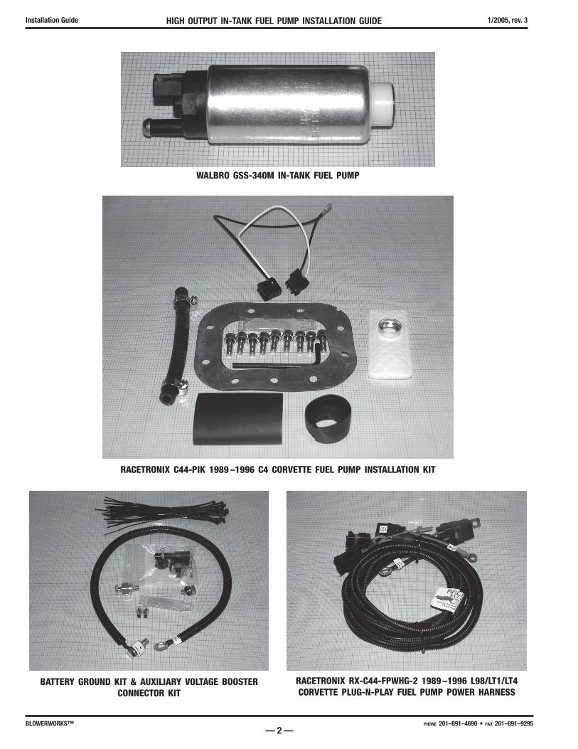
WALBRO GSS-340M IN-TANK FUEL PUMP
RACETRONIX C44-PIK 1989 –1996 C4 CORVETTE FUEL PUMP INSTALLATION KIT
BATTERY GROUND KIT & AUXILIARY VOLTAGE BOOSTER CONNECTOR KIT
RACETRONIX RX-C44-FPWHG-2 1989 –1996 L98/LT1/LT4 CORVETTE PLUG-N-PLAY FUEL PUMP POWER HARNESS
HIGH OUTPUT IN-TANK FUEL PUMP INSTALLATION GUIDE Installation Guide1/2005, rev. 3
— 3 —BLOWERWORKS™ PHONE 201–891–4690 • FAX 201–891–9295
INTRODUCTIONThank you for choosing the Racetronix High Output – High Volume In-Tank fuel pump replacement kit for your 1989 thru 1996 C4 Corvette. You have made a very wise decision. There is no finer exact replace-ment fuel pump made for your vehicle. The Walbro GSS-340M fuel pump more than doubles the available volume of fuel @ 60 psig compared to the stock fuel pump. See the accompanying fuel pump graph that compare the two pumps.
Perhaps equally important as the pump itself is the included in-tank wiring harness that is part of your kit. This harness uses 14 gage Teflon wire to ensure that all available voltage reaches your new pump. All fuel pumps capacity varies enormously as a function of voltage. Voltage variations as small as .5vdc can result in greatly diminished capacity. The new harness with its’ new wiring and fresh terminals guar-antees optimum pump performance.
Another greatly appreciated convenience of this kit is the new tank gasket and stainless steel screws with new O rings. When disassembling a fuel tree that is 10 to 20 years old the new gasket and screws assure a tight seal – very important. Note your kit also includes silicone grease. Use the grease to coat both sides of your new gasket. If available you might want to use a power wire wheel to clean up the surfaces of the fuel tank and fuel tree. Use caution if you need clean the fuel tank surface – dangerous gasoline fumes could result in fire or explosion.
You can also use the silicone grease to lubricate the electrical pins on the fuel tree bulkhead connector to assure a tight seal.
As part of this installation we strongly recommend you replace the fuel filter. The filter easily ‘clogs’ and should be replaced every 10,000 miles on a supercharged vehicle.
Finally, if your RWHP exceeds 500 you may want to consider purchasing the Racetronix mating Plug-N-Play external wiring harness for your new fuel pump. This harness will result in over a 1 volt dc increase at the pump head – a substantial increase that will result in more fuel. Additionally this harness will support an optional in-line booster pump (GSL-392) and/or a pump voltage booster. These additions can support in excess of 1000 RWHP!!!

HIGH OUTPUT IN-TANK FUEL PUMP INSTALLATION GUIDEInstallation Guide 1/2005, rev. 3
— 4 —BLOWERWORKS™ PHONE 201–891–4690 • FAX 201–891–9295
NOTES
HIGH OUTPUT IN-TANK FUEL PUMP INSTALLATION GUIDE Installation Guide1/2005, rev. 3
— 5 —BLOWERWORKS™ PHONE 201–891–4690 • FAX 201–891–9295
STOCK FUEL PUMP REMOVAL 1. Disconnect negative (Ground) battery cable. 2. Remove fuel pump 10 ampere blade fuse. Fuse is located in the passenger side Instrument Panel Console Fuse
Center. 3. Relieve fuel system pressure. 4. Remove the Fuel Filler Door (4 T-15 Torx). 5. Remove fuel filler cap. 6. Remove rubber fuel spill catch surrounding filler tube. Pull up on rubber and disconnect overflow drain hose as
you do so. 7. Disconnect the electrical connector to the fuel tree. Remember to pull the safety clip first. 8. Loosen the hose clamps on the fuel supply, fuel return, and fuel vapor recovery rubber hoses. Pull the fuel
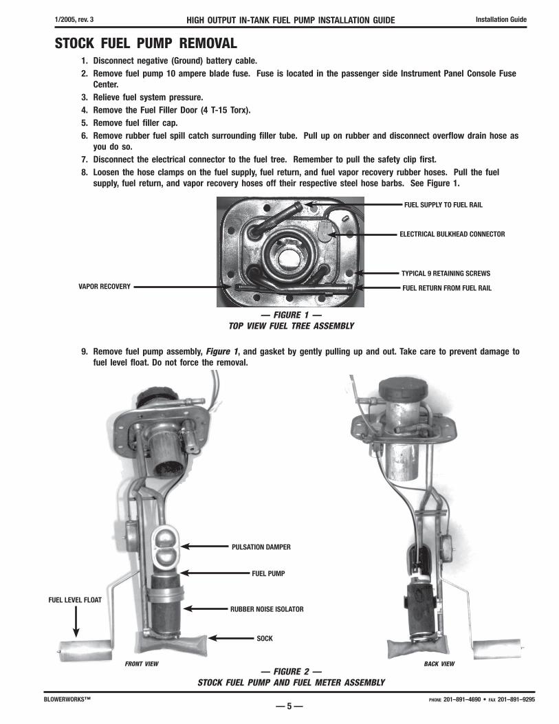
supply, fuel return, and vapor recovery hoses off their respective steel hose barbs. See Figure 1.
9. Remove fuel pump assembly, Figure 1, and gasket by gently pulling up and out. Take care to prevent damage to fuel level float. Do not force the removal.
— FIGURE 2 —STOCK FUEL PUMP AND FUEL METER ASSEMBLY
FRONT VIEW BACK VIEW
— FIGURE 1 —TOP VIEW FUEL TREE ASSEMBLY
VAPOR RECOVERY
FUEL SUPPLY TO FUEL RAIL
ELECTRICAL BULKHEAD CONNECTOR
TYPICAL 9 RETAINING SCREWS
FUEL RETURN FROM FUEL RAIL
RUBBER NOISE ISOLATOR
PULSATION DAMPER
SOCK
FUEL PUMP
FUEL LEVEL FLOAT

HIGH OUTPUT IN-TANK FUEL PUMP INSTALLATION GUIDEInstallation Guide 1/2005, rev. 3
— 6 —BLOWERWORKS™ PHONE 201–891–4690 • FAX 201–891–9295
10. Note the position of the stock Delco fuel pick-up 'sock' prior to disassembly. The new pump and sock should match.
2. Disconnect the electrical wires at the pump using a small-bladed screwdriver to pop off.
— FIGURE 4A & 4B —UNPLUG PUMP POWER CONNECTOR
— FIGURE 3 —STOCK FUEL PUMP CLOSE-UP
NOTE SCREEN HEIGHT RELATIVE TO FLOAT
PUMP POWER ELECTRIC
CONNECTOR

HIGH OUTPUT IN-TANK FUEL PUMP INSTALLATION GUIDE Installation Guide1/2005, rev. 3
— 7 —BLOWERWORKS™ PHONE 201–891–4690 • FAX 201–891–9295
12. Remove the stock Delco pump and pulsation dampener.
— FIGURE 6 —RELEASE BULKHEAD CONNECTOR BY PUSHING ON LOCK TAB AND PULLING UP AT THE SAME TIME.
— FIGURE 5 —
STOCK DELCO PUMP REMOVEDPULL PULSATION DAMPER OFF SUPPLY PIPE
REMOVE PULSATION DAMPENER
13. Remove the fuel pump power and fuel level sensor connector from the bulkhead connector. See Figure 6.

HIGH OUTPUT IN-TANK FUEL PUMP INSTALLATION GUIDEInstallation Guide 1/2005, rev. 3
— 8 —BLOWERWORKS™ PHONE 201–891–4690 • FAX 201–891–9295
14. Now remove the purple colored fuel level sensor wire from its connector. Use the supplied paper clip to release the electrical pin by inserting it into the connector as shown in Figure 7.
15. Next remove the 2 black colored ground wires from the fuel level sensor. See Figures 8 & 9.
— FIGURE 8 —
— FIGURE 7 —PAPER CLIP RELEASES TERMINAL-INSERT PAPER CLIP & PULL ON PURPLE WIRE.
— FIGURE 9 —
FEMALE ¼˝ PUSH TERMINALPULL TO REMOVE FUEL SENSOR GROUND POINT
CONGRATULATIONS YOU’VE NOW COMPLETELY REMOVED THE STOCK FUEL PUMP & FUEL LEVEL SENSOR WIRING ASSEMBLY. IT WILL BE REPLACED WITH THE NEW HARNESS SUPPLIED AS PART OF YOUR KIT.

HIGH OUTPUT IN-TANK FUEL PUMP INSTALLATION GUIDE Installation Guide1/2005, rev. 3
— 9 —BLOWERWORKS™ PHONE 201–891–4690 • FAX 201–891–9295
16. Your fuel tree should now look like Figure 10 shown below.
— FIGURE 10 —
HIGH OUTPUT IN-TANK FUEL PUMP INSTALLATION GUIDEInstallation Guide 1/2005, rev. 3
— 10 —BLOWERWORKS™ PHONE 201–891–4690 • FAX 201–891–9295
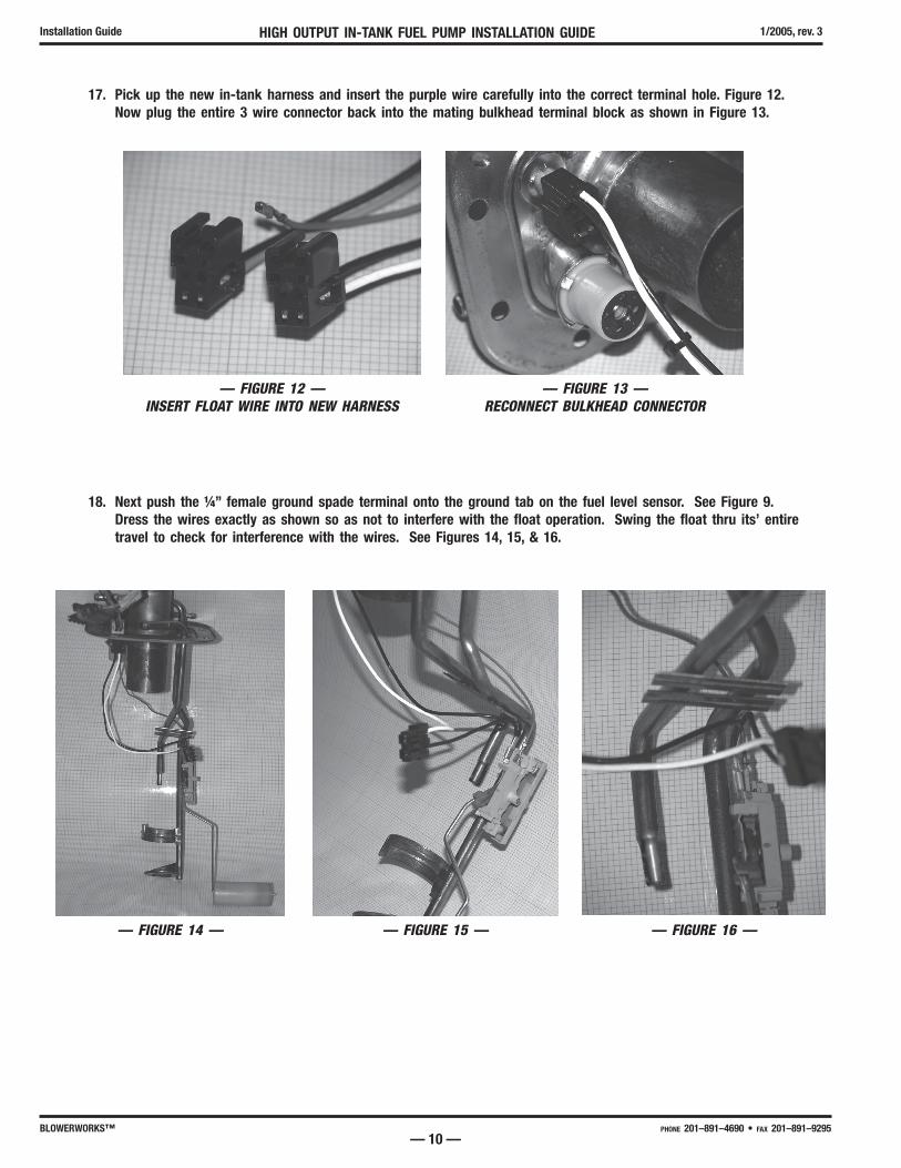
17. Pick up the new in-tank harness and insert the purple wire carefully into the correct terminal hole. Figure 12. Now plug the entire 3 wire connector back into the mating bulkhead terminal block as shown in Figure 13.
18. Next push the ¼” female ground spade terminal onto the ground tab on the fuel level sensor. See Figure 9. Dress the wires exactly as shown so as not to interfere with the float operation. Swing the float thru its’ entire travel to check for interference with the wires. See Figures 14, 15, & 16.
— FIGURE 12 —INSERT FLOAT WIRE INTO NEW HARNESS
— FIGURE 13 —RECONNECT BULKHEAD CONNECTOR
— FIGURE 14 — — FIGURE 15 — — FIGURE 16 —

HIGH OUTPUT IN-TANK FUEL PUMP INSTALLATION GUIDE Installation Guide1/2005, rev. 3
— 11 —BLOWERWORKS™ PHONE 201–891–4690 • FAX 201–891–9295
19. Slide the foam rubber noise isolator over the new fuel pump as shown in Figure 17.
— FIGURE 17 —INSTALL FOAM RUBBER NOISE ISOLATOR
20. Next slip the rubber “booty” over the bottom of the pump as shown in Figures 18 & 19. Note the orientation of the ‘tip’ to the discharge of the pump – they should be 180 degrees apart. The reason will be seen in the next photo where the pump discharge must be aligned with the fuel supply line.
21. Align the pump discharge with the fuel supply line. Note the rubber “booty” should be seated solidly in the pump foot holder.
— FIGURE 18 —PUMP & RUBBER "BOOTY"
— FIGURE 19 —NOTE ORIENTATION OF BOOTY TIP TO PUMP
DISCHARGE
— FIGURE 20 — — FIGURE 21 —
"BOOTY" SETSDOWN SOLIDIN FOOT

HIGH OUTPUT IN-TANK FUEL PUMP INSTALLATION GUIDEInstallation Guide 1/2005, rev. 3
— 12 —BLOWERWORKS™ PHONE 201–891–4690 • FAX 201–891–9295
22. Measure distance as shown in Figure 20 and cut your hose to suit. Mine was 2” long as shown.
23. The supplied hose is 5/16” id and fits the pump discharge perfectly. The steel supply line is 3/8” od with a taper down 5/16” x 1” long nipple. Slide the 2” hose onto the fuel tree pushing it up as far as it will go. Slide on both hose clamps. Insert the fuel pump into the hose end while reseating into foot. All should align perfectly for a beautiful install as shown. Sometimes you have to re-shape the pump side saddle to fit nicely. Insert fuel pump power connector into pump head.
24. Neatly ty-wrap all wires as shown below. Be sure the fuel sensor float is free to move thru its’ entire travel with-out contacting any wires.

HIGH OUTPUT IN-TANK FUEL PUMP INSTALLATION GUIDE Installation Guide1/2005, rev. 3
— 13 —BLOWERWORKS™ PHONE 201–891–4690 • FAX 201–891–9295
25. Carefully push the new white ‘sock’ onto the bottom of the pump.
26. You are now done with the pump assembly. Does your install look like this?
HIGH OUTPUT IN-TANK FUEL PUMP INSTALLATION GUIDEInstallation Guide 1/2005, rev. 3
— 14 —BLOWERWORKS™ PHONE 201–891–4690 • FAX 201–891–9295
FUEL TREE INSTALLATION 27. Reverse the removal procedure. Remember to coat the new tank gasket with the supplied silicone grease. You
may also want to coat the new retaining screws with some grease.
28. Inspect all your GM rubber fuel hoses for cracking. If cracked either cut back an inch or replace. Use a little bit of silicone grease to coat the steel tubes prior to sliding the rubber hoses back on. Secure all hoses with the original hose clamps.
29. Reconnect the electrical connector. Insert the key lock.
30. Replace the 10 amp fuel pump fuse with the supplied 15 amp.
31. Re-connect the battery ground cable.
32. Turn the ignition key to on without starting the engine. Due this several times to prime the fuel rail. Each time you do this (wait 10 seconds between each on time) the fuel pump should run for two seconds. Check for fuel leaks prior to starting the engine. If OK start the engine and again immediately check for fuel leaks at the fuel tank hose connections. Very carefully gently squeeze the return line rubber hose with duck nose pliers. Doing so will result in a fuel rail pressure in excess of 100 psig. Subsequently the engine will stall. The purpose of doing this is to test the integrity of all your hose tank connections at very high pressure. Look for leaks.
33. Leave the fuel door off while you perform your over the open road test.
34. With the fuel tank at ¼ full perform a WOT (Wide Open Throttle) test. The fuel pressure should rise with boost pressure if so equipped with a blower. Fuel pressure must always rise with manifold pressure; typically at a 1:1 ratio (1 pound boost equals 1 more pound fuel pressure) unless using a FMU. If using a FMU the fuel pressure should rise quicker than manifold pressure. The rate of rise is dependent on the FMU ratio, injector size, and available pump head. A typical fuel pressure reading with 10 pounds of boost pressure would be 55 to 60 psig. If less than or if fuel pressure falls as manifold pressure rises there is a problem. Some possible causes:
a. Clogged or dirty fuel filter
b. Inadequate voltage at the pump head
c. Not enough pump head for the application (i.e., you need to supplement the in-tank pump with an in-line booster pump or a pump voltage booster).
35. Inspect your fuel tank hose connections one more time. If all is OK re-install the fuel door cover.
CAUTION THIS TEST REQUIRES TWO PEOPLE!!! ONE TO OBSERVE AND ONE TO DRIVE. DO NOT DO THIS TEST BY YOURSELF: IT IS TOO DANGEROUS!
CONGRATULATIONS You are now done! We hope your experience has been a positive one. All comments and feedback are appreciated: Pros & Cons!

HIGH OUTPUT IN-TANK FUEL PUMP INSTALLATION GUIDE Installation Guide1/2005, rev. 3
— 15 —BLOWERWORKS™ PHONE 201–891–4690 • FAX 201–891–9295
…Other BLOWERWORKS™ Products…
• PROFESSIONAL SUPERCHARGING KITS FOR C4, C5, & C6 CORVETTES
• WORLD’S LARGEST ASSORTMENT OF WATER/ALCOHOL INJECTION SYSTEMS
• SUPPLEMENTAL FUEL INJECTION SYSTEMS
• PULSE WIDTH MODULATED CLOSED LOOP FUEL PUMP CONTROLLERS
T h a n k Yo u Fo r C h o o s i n g
ALSO ASK ABOUT THESE INCREDIBLE PRODUCTS ALSO BROUGHT TO YOU BY BLOWERWORKS™
SUPERFUELER™ & SUPERPUMPER-II™