vishay dale resistors
TRANSCRIPT
8/18/2019 Vishay Dale Resistors
http://slidepdf.com/reader/full/vishay-dale-resistors 1/8
Document Number: 20035 For technical questions, contact: [email protected] www.vishay.comRevision: 04-Jun-12 125
D/CRCW e3
Vishay
Standard Thick Film Chip Resistors
THIS DOCUMENT IS SUBJECT TO CHANGE WITHOUT NOTICE. THE PRODUCTS DESCRIBED HEREIN AND THIS DOCUMENTARE SUBJECT TO SPECIFIC DISCLAIMERS, SET FORTH AT www.vishay.com/doc?91000
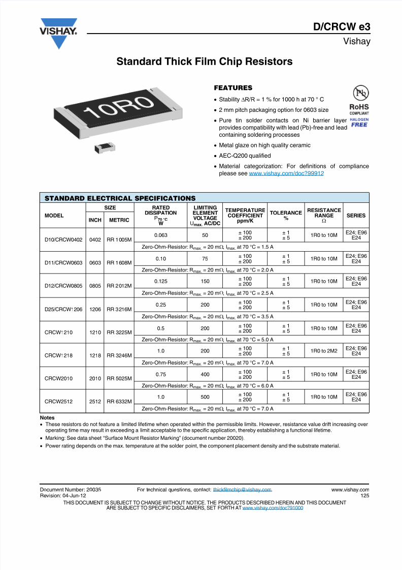
FEATURES
Stability R / R = 1 % for 1000 h at 70 ° C
2 mm pitch packaging option for 0603 size
Pure tin solder contacts on Ni barrier layer
provides compatibility with lead (Pb)-free and lead
containing soldering processes
Metal glaze on high quality ceramic
AEC-Q200 qualified
Material categorization: For definitions of compliance
please see www.vishay.com/doc?99912
Notes
These resistors do not feature a limited lifetime when operated within the permissible limits. However, resistance value drift increasing overoperating time may result in exceeding a limit acceptable to the specific application, thereby establishing a functional lifetime.
Marking: See data sheet “Surface Mount Resistor Marking” (document number 20020).
Power rating depends on the max. temperature at the solder point, the component placement density and the substrate material.
STANDARD ELECTRICAL SPECIFICATIONS
MODEL
SIZE RATEDDISSIPATION
P70 °CW
LIMITINGELEMENTVOLTAGEUmax. AC/DC
TEMPERATURECOEFFICIENT
ppm/K
TOLERANCE%
RESISTANCERANGE
SERIES
INCH METRIC
D10/CRCW0402 0402 RR 1005M0.063 50
± 100± 200
± 1± 5
1R0 to 10ME24; E96
E24
Zero-Ohm-Resistor: Rmax. = 20 m, Imax. at 70 °C = 1.5 A
D11/CRCW0603 0603 RR 1608M0.10 75
± 100± 200
± 1± 5
1R0 to 10ME24; E96
E24
Zero-Ohm-Resistor: Rmax. = 20 m, Imax. at 70 °C = 2.0 A
D12/CRCW0805 0805 RR 2012M0.125 150
± 100± 200
± 1± 5
1R0 to 10ME24; E96
E24
Zero-Ohm-Resistor: Rmax. = 20 m, Imax. at 70 °C = 2.5 A
D25/CRCW1206 1206 RR 3216M0.25 200 ± 100
± 200± 1± 5
1R0 to 10M E24; E96E24
Zero-Ohm-Resistor: Rmax. = 20 m, Imax. at 70 °C = 3.5 A
CRCW1210 1210 RR 3225M0.5 200
± 100± 200
± 1± 5
1R0 to 10ME24; E96
E24
Zero-Ohm-Resistor: Rmax. = 20 m, Imax. at 70 °C = 5.0 A
CRCW1218 1218 RR 3246M1.0 200
± 100± 200
± 1± 5
1R0 to 2M2E24; E96
E24
Zero-Ohm-Resistor: Rmax. = 20 m, Imax. at 70 °C = 7.0 A
CRCW2010 2010 RR 5025M0.75 400
± 100± 200
± 1± 5
1R0 to 10ME24; E96
E24
Zero-Ohm-Resistor: Rmax. = 20 m, Imax. at 70 °C = 6.0 A
CRCW2512 2512 RR 6332M1.0 500
± 100
± 200
± 1
± 51R0 to 10M
E24; E96
E24
Zero-Ohm-Resistor: Rmax. = 20 m, Imax. at 70 °C = 7.0 A
8/18/2019 Vishay Dale Resistors
http://slidepdf.com/reader/full/vishay-dale-resistors 2/8
www.vishay.com For technical questions, contact: [email protected] Document Number: 20035126 Revision: 04-Jun-12
D/CRCW e3
Vishay Standard Thick Film Chip Resistors
THIS DOCUMENT IS SUBJECT TO CHANGE WITHOUT NOTICE. THE PRODUCTS DESCRIBED HEREIN AND THIS DOCUMENTARE SUBJECT TO SPECIFIC DISCLAIMERS, SET FORTH AT www.vishay.com/doc?91000
Note(1) The power dissipation on the resistor generates a temperature rise against the local ambient, depending on the heat flow support of the
printed-circuit board (thermal resistance). The rated dissipation applies only if the permitted film temperature of 155 °C is not exceeded.
TECHNICAL SPECIFICATIONS
PARAMETER UNITD10/
CRCW0402D11/
CRCW0603D12/
CRCW0805D25/
CRCW1206CRCW1210 CRCW1218 CRCW2010 CRCW2512
Rated dissipation P70 (1) W 0.063 0.1 0.125 0.25 0.5 1.0 0.75 1.0
Limiting element voltageUmax. AC/DC
V 50 75 150 200 200 200 400 500
Insulation voltageUins (1 min)
V > 75 > 100 > 200 > 300 > 300 > 300 > 300 > 300
Insulation resistance > 109
Category temperature
range°C - 55 to + 155
Failure rate h-1 < 0.1 x 10- 9
Weight mg 0.65 2 5.5 10 16 29.5 25.5 40.5
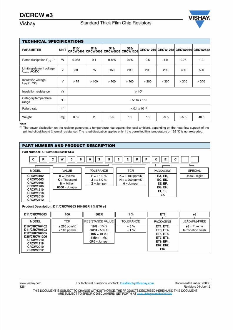
PART NUMBER AND PRODUCT DESCRIPTION
Part Number: CRCW0603562RFKEC
MODEL VALUE TOLERANCE TCR PACKAGING SPECIAL
CRCW0402CRCW0603CRCW0805CRCW1206CRCW1210CRCW1218CRCW2010CRCW2512
R = Decimal
K = Thousand
M = Million
0000 = Jumper
F = ± 1.0 %
J = ± 5.0 %
Z = Jumper
K = ± 100 ppm/K
N = ± 200 ppm/K
0 = Jumper
EA, EB,
EC, ED,
EE, EF,
EG, EH,
EI, EL,
EK
Up to 2 digits
Product Description: D11/CRCW0603 100 562R 1 % ET6 e3
D11/CRCW0603 100 562R 1 % ET6 e3
MODEL TCR RESISTANCE VALUE TOLERANCE PACKAGING LEAD (Pb)-FREE
D10/CRCW0402
D11/CRCW0603D12/CRCW0805D25/CRCW1206
CRCW1210CRCW1218CRCW2010CRCW2512
± 200 ppm/K
± 100 ppm/K
10R = 10
562R = 562 10K = 10 k
1M0 = 1 M
0R0 = Jumper
± 5 %
± 1 %
ET1, ET2,
ET3, ET4,ET5, ET6,
ET7, ET8,
ET9, EF4,
E02, E67,
E82
e3 = Pure tin
termination finish
C R C W 0 6 0 3 5 6 2 R F K E C
8/18/2019 Vishay Dale Resistors
http://slidepdf.com/reader/full/vishay-dale-resistors 3/8
Document Number: 20035 For technical questions, contact: [email protected] www.vishay.comRevision: 04-Jun-12 127
D/CRCW e3Standard Thick Film Chip Resistors Vishay
THIS DOCUMENT IS SUBJECT TO CHANGE WITHOUT NOTICE. THE PRODUCTS DESCRIBED HEREIN AND THIS DOCUMENTARE SUBJECT TO SPECIFIC DISCLAIMERS, SET FORTH AT www.vishay.com/doc?91000
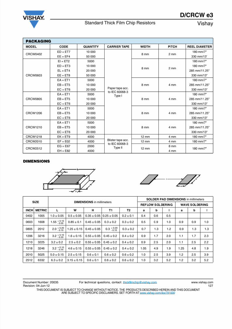
DIMENSIONS
PACKAGING
MODEL CODE QUANTITY CARRIER TAPE WIDTH PITCH REEL DIAMETER
CRCW0402ED = ET7 10 000
Paper tape acc.
to IEC 60068-3
Type I
8 mm 2 mm180 mm/7"
EE = EF4 50 000 330 mm/13"
CRCW0603
EI = ET2 5000
8 mm 2 mm
180 mm/7"
ED = ET3 10 000 180 mm/7"
EL = ET4 20 000 285 mm/11.25"
EE = ET8 50 000 330 mm/13"
EA = ET1 5000
8 mm 4 mm
180 mm/7"
EB = ET5 10 000 285 mm/11.25"
EC = ET6 20 000 330 mm/13"
CRCW0805
EA = ET1 5000
8 mm 4 mm
180 mm/7"
EB = ET5 10 000 285 mm/11.25"
EC = ET6 20 000 330 mm/13"
CRCW1206
EA = ET1 5000
8 mm 4 mm
180 mm/7"
EB = ET5 10 000 285 mm/11.25"
EC = ET6 20 000 330 mm/13"
CRCW1210
EA = ET1 5000
8 mm 4 mm
180 mm/7"
EB = ET5 10 000 285 mm/11.25"
EC = ET6 20 000 330 mm/13"
CRCW1218 EK = ET9 4000Blister tape acc.
to IEC 60068-3
Type II
12 mm 4 mm 180 mm/7"
CRCW2010 EF = E02 4000 12 mm 4 mm 180 mm/7"
CRCW2512EG = E67 2000
12 mm8 mm
180 mm/7"EH = E82 4000 4 mm
SIZE DIMENSIONS in millimetersSOLDER PAD DIMENSIONS in millimeters
REFLOW SOLDERING WAVE SOLDERING
INCH METRIC L W H T1 T2 a b l a b l
0402 1005 1.0 ± 0.05 0.5 ± 0.05 0.35 ± 0.05 0.25 ± 0.05 0.2 ± 0.1 0.4 0.6 0.5
0603 1608 1.55 + 0.10- 0.05 0.85 ± 0.1 0.45 ± 0.05 0.3 ± 0.2 0.3 ± 0.2 0.5 0.9 1.0 0.9 0.9 1.0
0805 2012 2.0
+ 0.20
- 0.10 1.25 ± 0.15 0.45 ± 0.05 0.3
+ 0.20
- 0.10 0.3 ± 0.2 0.7 1.3 1.2 0.9 1.3 1.3
1206 3216 3.2 + 0.10- 0.20 1.6 ± 0.15 0.55 ± 0.05 0.45 ± 0.2 0.4 ± 0.2 0.9 1.7 2.0 1.1 1.7 2.3
1210 3225 3.2 ± 0.2 2.5 ± 0.2 0.55 ± 0.05 0.45 ± 0.2 0.4 ± 0.2 0.9 2.5 2.0 1.1 2.5 2.2
1218 3246 3.2 + 0.10- 0.20 4.6 ± 0.15 0.55 ± 0.05 0.45 ± 0.2 0.4 ± 0.2 1.05 4.9 1.9 1.25 4.8 1.9
2010 5025 5.0 ± 0.15 2.5 ± 0.15 0.6 ± 0.1 0.6 ± 0.2 0.6 ± 0.2 1.0 2.5 3.9 1.2 2.5 3.9
2512 6332 6.3 ± 0.2 3.15 ± 0.15 0.6 ± 0.1 0.6 ± 0.2 0.6 ± 0.2 1.0 3.2 5.2 1.2 3.2 5.2
8/18/2019 Vishay Dale Resistors
http://slidepdf.com/reader/full/vishay-dale-resistors 4/8
www.vishay.com For technical questions, contact: [email protected] Document Number: 20035128 Revision: 04-Jun-12
D/CRCW e3
Vishay Standard Thick Film Chip Resistors
THIS DOCUMENT IS SUBJECT TO CHANGE WITHOUT NOTICE. THE PRODUCTS DESCRIBED HEREIN AND THIS DOCUMENTARE SUBJECT TO SPECIFIC DISCLAIMERS, SET FORTH AT www.vishay.com/doc?91000
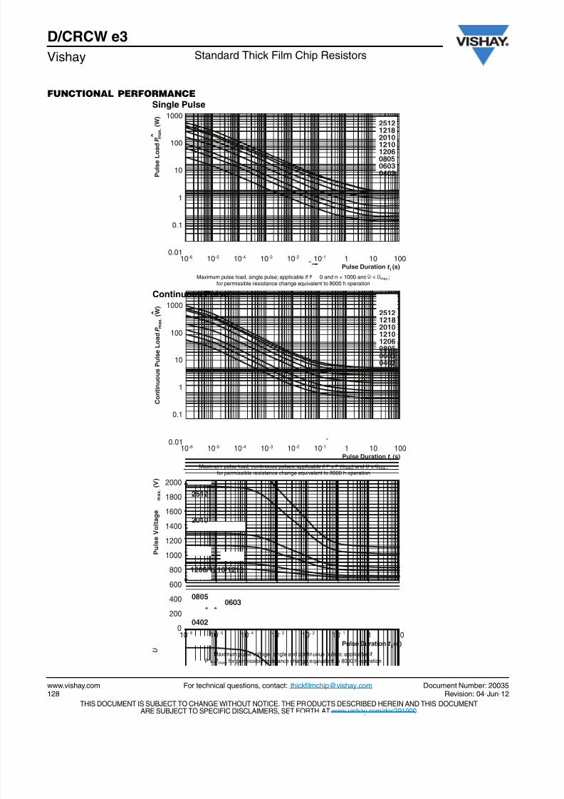
FUNCTIONAL PERFORMANCE
1000
100
10
1
0.1
0.01
Single Pulse
P u l s e L o a d
m a x .
( W )
P
25121218
201012101206080506030402
10-6 Pulse Duration
i (s)t
10-5 10-4 10-3 10-2 10-1 1 10 100
Maximum p
ulse load, single p
ulse; applica
ble if
P 0 and n < 1000 and
Û ≤
Û
max.;for permissible resistance change equivalent to 8000 h operation
1000
10
1
0.1
0.0110-6
Continuous Pulse
Maximum pulse load, continuous pulses; applicable if P ≤ P (ϑamb) and Û ≤ Ûmax.;for permissible resistance change equivalent to 8000 h operation
Pulse Duration i (s)
C o n t i n u o u s P u l s e L o a d
m a x .
( W )
t
P 100
10-5 10-4 10-3 10-2 10-1 1 10 100
25121218201012101206080506030402
2000
200
010- 6 10- 5 10- 4 10- 3 10- 2 10- 1 1 10
Maximum pulse voltage, single and continuous pulses; applicable if
P ≤ Pmax.; for permissible resistance change equivalent to 8000 h operation
Pulse Duration i (s)
400
600
800
1000
1200
1400
1600
1800
P u l s e V o l t a g e
m a x .
( V )
2512
2010
1206/1210/1218
08050603
0402
t
8/18/2019 Vishay Dale Resistors
http://slidepdf.com/reader/full/vishay-dale-resistors 5/8
Document Number: 20035 For technical questions, contact: [email protected] www.vishay.comRevision: 04-Jun-12 129
D/CRCW e3Standard Thick Film Chip Resistors Vishay
THIS DOCUMENT IS SUBJECT TO CHANGE WITHOUT NOTICE. THE PRODUCTS DESCRIBED HEREIN AND THIS DOCUMENTARE SUBJECT TO SPECIFIC DISCLAIMERS, SET FORTH AT www.vishay.com/doc?91000
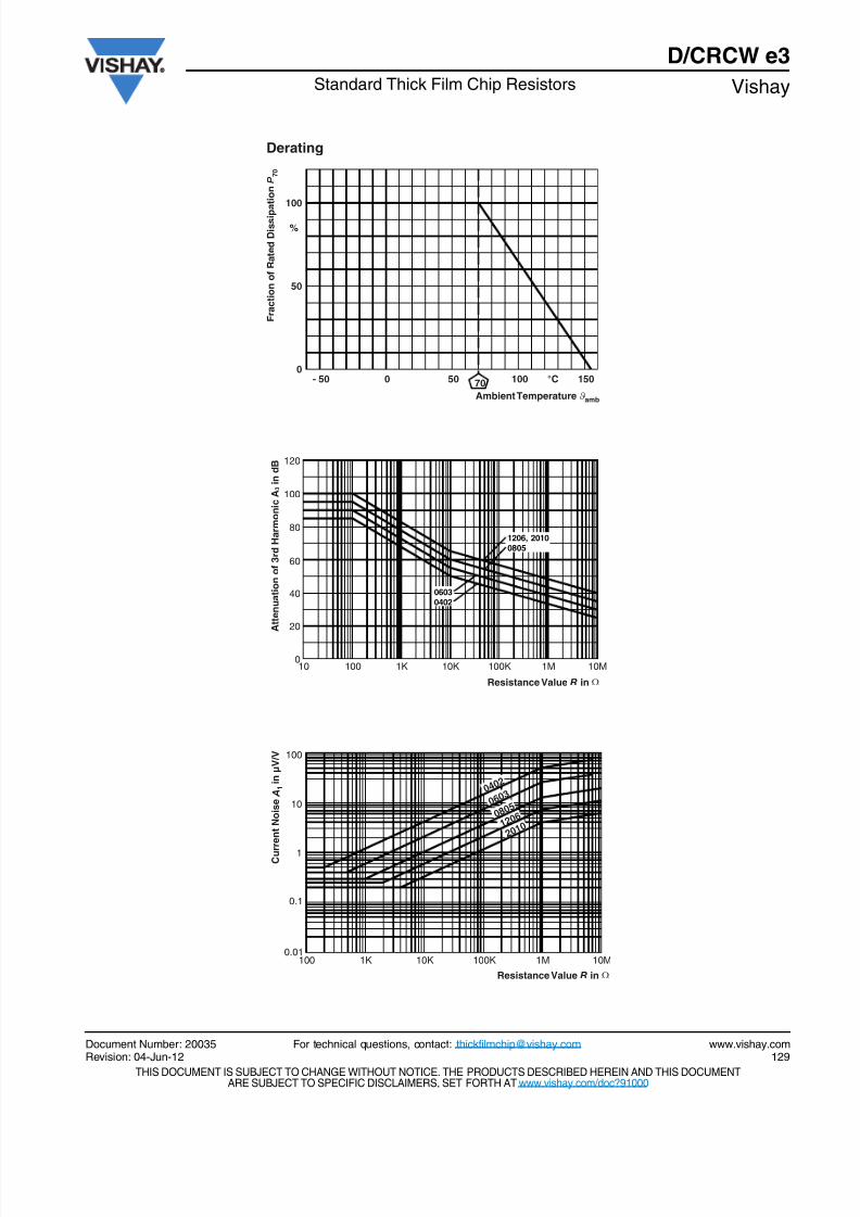
- 50 0 50 100 1500
Derating
Ambient Temperature amb
F r a c t i o n o f R a t e d D i s s i p
a t i o n P 7 0
50
100
70 °C
%
ϑ
10
120
Resistance Value R in Ω
A t t e n u a t i o n o f 3 r d H a r m o n i c A 3 i n d B
100
80
40
60
20
0100 1K 10K 100K 1M 10M
1206, 2010
0805
0603
0402
100 1K 10K 100K 1M 10M
100
10
1
0.1
0.01
C u r r e n t N o i s e A 1 i n µ V / V
2 0 1 0
1 2 0 6
0 8 0 5
0 6 0 3
0 4 0 2
Resistance Value R in Ω
8/18/2019 Vishay Dale Resistors
http://slidepdf.com/reader/full/vishay-dale-resistors 6/8
www.vishay.com For technical questions, contact: [email protected] Document Number: 20035130 Revision: 04-Jun-12
D/CRCW e3
Vishay Standard Thick Film Chip Resistors
THIS DOCUMENT IS SUBJECT TO CHANGE WITHOUT NOTICE. THE PRODUCTS DESCRIBED HEREIN AND THIS DOCUMENTARE SUBJECT TO SPECIFIC DISCLAIMERS, SET FORTH AT www.vishay.com/doc?91000
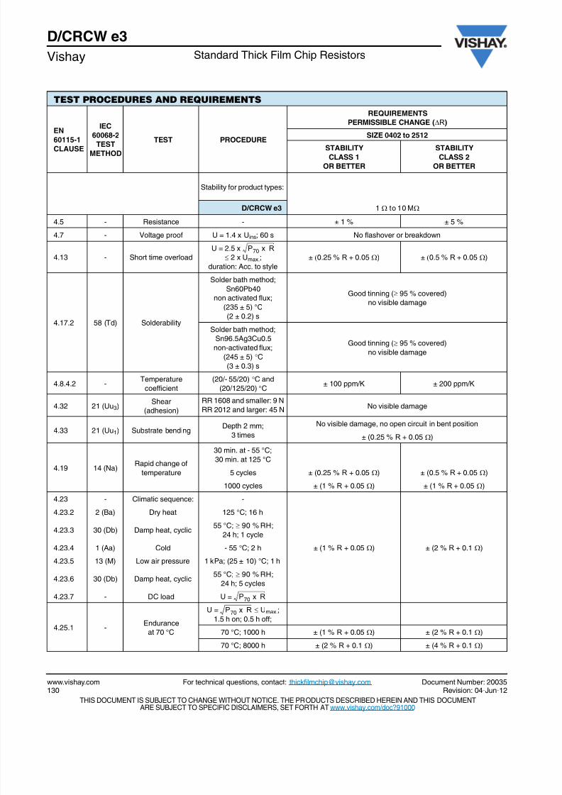
TEST PROCEDURES AND REQUIREMENTS
EN
60115-1CLAUSE
IEC
60068-2TEST
METHOD
TEST PROCEDURE
REQUIREMENTS
PERMISSIBLE CHANGE (R)
SIZE 0402 to 2512STABILITY
CLASS 1
OR BETTER
STABILITY
CLASS 2
OR BETTER
Stability for product types:
D/CRCW e3 1 to 10 M
4.5 - Resistance - ± 1 % ± 5 %
4.7 - Voltage proof U = 1.4 x Uins; 60 s No flashover or breakdown
4.13 - Short time overload
U = 2.5 x
2 x Umax.;
duration: Acc. to style
± 0.25 % R + 0.05 ) ± 0.5 % R + 0.05 )
4.17.2 58 (Td) Solderability
Solder bath method;Sn60Pb40
non activated flux;
(235 ± 5) °C
(2 ± 0.2) s
Good tinning ( 95 % covered)
no visible damage
Solder bath method;
Sn96.5Ag3Cu0.5
non-activated flux;
(245 ± 5) C
(3 ± 0.3) s
Good tinning ( 95 % covered)
no visible damage
4.8.4.2 -Temperature
coefficient
(20/- 55/20) C and
(20/125/20) C± 100 ppm/K ± 200 ppm/K
4.32 21 (Uu3)Shear
(adhesion)
RR 1608 and smaller: 9 N
RR 2012 and larger: 45 NNo visible damage
4.33 21 (Uu1) Substrate bendingDepth 2 mm;
3 times
No visible damage, no open circuit in bent position
± (0.25 % R + 0.05 )
4.19 14 (Na)Rapid change of
temperature
30 min. at - 55 °C;
30 min. at 125 °C
5 cycles ± (0.25 % R + 0.05 ) ± (0.5 % R + 0.05 )
1000 cycles ± (1 % R + 0.05 ) ± (1 % R + 0.05 )
4.23 - Climatic sequence: -
± (1 % R + 0.05 ) ± (2 % R + 0.1 )
4.23.2 2 (Ba) Dry heat 125 °C; 16 h
4.23.3 30 (Db) Damp heat, cyclic55 °C; 90 % RH;
24 h; 1 cycle
4.23.4 1 (Aa) Cold - 55 °C; 2 h
4.23.5 13 (M) Low air pressure 1 kPa; (25 ± 10) °C; 1 h
4.23.6 30 (Db) Damp heat, cyclic55 °C; 90 % RH;
24 h; 5 cycles
4.23.7 - DC load U =
4.25.1 -Endurance
at 70 °C
U = Umax.;
1.5 h on; 0.5 h off;
70 °C; 1000 h ± (1 % R + 0.05 ) ± (2 % R + 0.1 )
70 °C; 8000 h ± (2 % R + 0.1 ) ± (4 % R + 0.1 )
P70 x R
P70 x R
P70 x R
8/18/2019 Vishay Dale Resistors
http://slidepdf.com/reader/full/vishay-dale-resistors 7/8
Document Number: 20035 For technical questions, contact: [email protected] www.vishay.comRevision: 04-Jun-12 131
D/CRCW e3Standard Thick Film Chip Resistors Vishay
THIS DOCUMENT IS SUBJECT TO CHANGE WITHOUT NOTICE. THE PRODUCTS DESCRIBED HEREIN AND THIS DOCUMENTARE SUBJECT TO SPECIFIC DISCLAIMERS, SET FORTH AT www.vishay.com/doc?91000
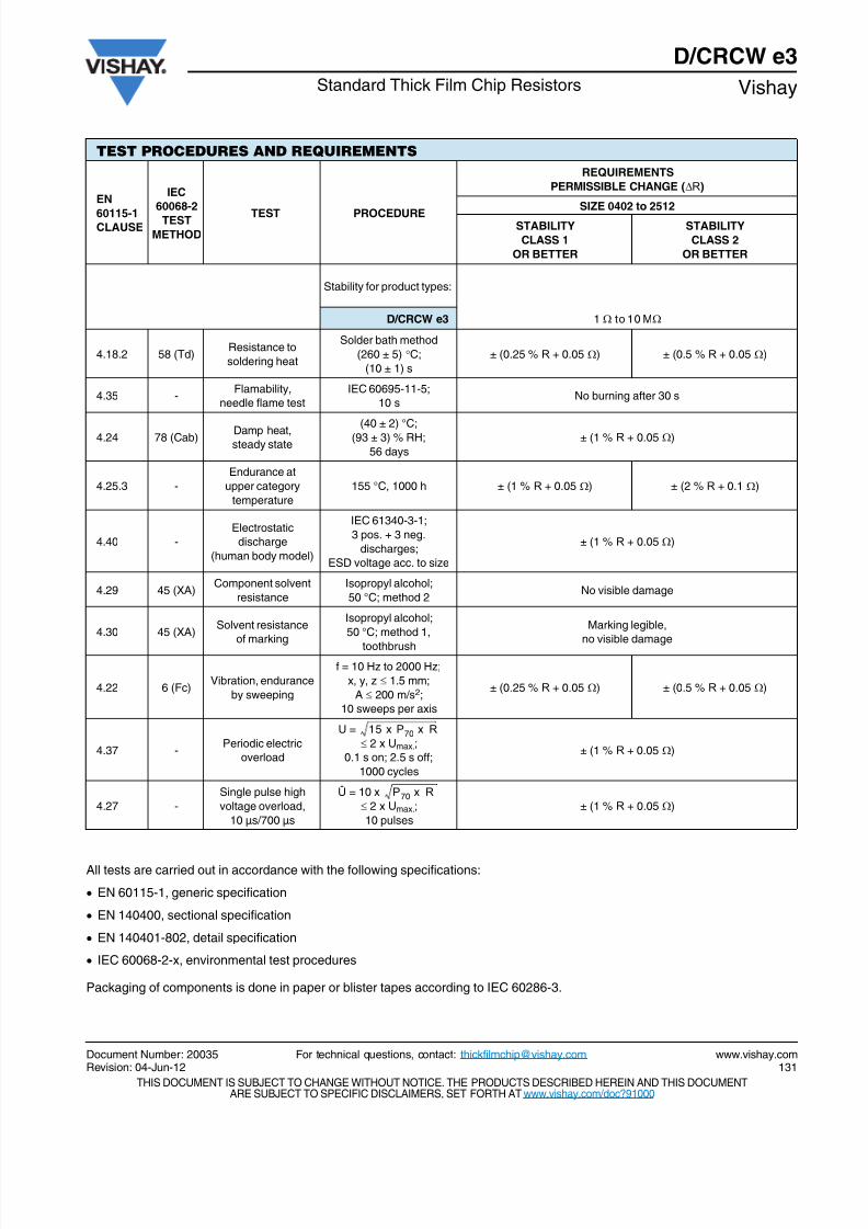
All tests are carried out in accordance with the following specifications:
EN 60115-1, generic specification
EN 140400, sectional specification
EN 140401-802, detail specification
IEC 60068-2-x, environmental test procedures
Packaging of components is done in paper or blister tapes according to IEC 60286-3.
4.18.2 58 (Td)Resistance to
soldering heat
Solder bath method
(260 ± 5) C;
(10 ± 1) s
± (0.25 % R + 0.05 ) ± (0.5 % R + 0.05 )
4.35 -Flamability,
needle flame test
IEC 60695-11-5;
10 sNo burning after 30 s
4.24 78 (Cab) Damp heat,steady state
(40 ± 2) °C;
(93 ± 3) % RH;
56 days
± (1 % R + 0.05 )
4.25.3 -
Endurance at
upper category
temperature
155 °C, 1000 h ± (1 % R + 0.05 ) ± (2 % R + 0.1 )
4.40 -
Electrostatic
discharge
(human body model)
IEC 61340-3-1;
3 pos. + 3 neg.
discharges;
ESD voltage acc. to size
± (1 % R + 0.05 )
4.29 45 (XA)Component solvent
resistance
Isopropyl alcohol;
50 °C; method 2No visible damage
4.30 45 (XA)Solvent resistance
of marking
Isopropyl alcohol;
50 °C; method 1,
toothbrush
Marking legible,
no visible damage
4.22 6 (Fc)Vibration, endurance
by sweeping
f = 10 Hz to 2000 Hz;
x, y, z 1.5 mm;
A 200 m/s2;
10 sweeps per axis
± (0.25 % R + 0.05 ) ± (0.5 % R + 0.05 )
4.37 -Periodic electric
overload
U =
2 x Umax.;
0.1 s on; 2.5 s off;
1000 cycles
± (1 % R + 0.05 )
4.27 -
Single pulse high
voltage overload,
10 µs/700 µs
Û = 10 x
2 x Umax.;
10 pulses
± (1 % R + 0.05 )
TEST PROCEDURES AND REQUIREMENTS
EN
60115-1CLAUSE
IEC
60068-2
TEST
METHOD
TEST PROCEDURE
REQUIREMENTS
PERMISSIBLE CHANGE (R)
SIZE 0402 to 2512
STABILITY
CLASS 1
OR BETTER
STABILITY
CLASS 2
OR BETTER
Stability for product types:
D/CRCW e3 1 to 10 M
15 x P70 x R
P70 x R
8/18/2019 Vishay Dale Resistors
http://slidepdf.com/reader/full/vishay-dale-resistors 8/8
Legal Disclaimer Noticewww.vishay.com Vishay
Revision: 02-Oct-12 1 Document Number: 91000
Disclaimer
ALL PRODUCT, PRODUCT SPECIFICATIONS AND DATA ARE SUBJECT TO CHANGE WITHOUT NOTICE TO IMPROVE
RELIABILITY, FUNCTION OR DESIGN OR OTHERWISE.
Vishay Intertechnology, Inc., its affiliates, agents, and employees, and all persons acting on its or their behalf (collectively,“Vishay”), disclaim any and all liability for any errors, inaccuracies or incompleteness contained in any datasheet or in any other
disclosure relating to any product.
Vishay makes no warranty, representation or guarantee regarding the suitability of the products for any particular purpose or
the continuing production of any product. To the maximum extent permitted by applicable law, Vishay disclaims (i) any and all
liability arising out of the application or use of any product, (ii) any and all liability, including without limitation special,
consequential or incidental damages, and (iii) any and all implied warranties, including warranties of fitness for particular
purpose, non-infringement and merchantability.
Statements regarding the suitability of products for certain types of applications are based on Vishay’s knowledge of typical
requirements that are often placed on Vishay products in generic applications. Such statements are not binding statements
about the suitability of products for a particular application. It is the customer’s responsibility to validate that a particular
product with the properties described in the product specification is suitable for use in a particular application. Parameters
provided in datasheets and/or specifications may vary in different applications and performance may vary over time. All
operating parameters, including typical parameters, must be validated for each customer application by the customer’s
technical experts. Product specifications do not expand or otherwise modify Vishay’s terms and conditions of purchase,
including but not limited to the warranty expressed therein.
Except as expressly indicated in writing, Vishay products are not designed for use in medical, life-saving, or life-sustaining
applications or for any other application in which the failure of the Vishay product could result in personal injury or death.
Customers using or selling Vishay products not expressly indicated for use in such applications do so at their own risk. Please
contact authorized Vishay personnel to obtain written terms and conditions regarding products designed for such applications.
No license, express or implied, by estoppel or otherwise, to any intellectual property rights is granted by this document or by
any conduct of Vishay. Product names and markings noted herein may be trademarks of their respective owners.
Material Category Policy Vishay Intertechnology, Inc. hereby certifies that all its products that are identified as RoHS-Compliant fulfill the
definitions and restrictions defined under Directive 2011/65/EU of The European Parliament and of the Council
of June 8, 2011 on the restriction of the use of certain hazardous substances in electrical and electronic equipment
(EEE) - recast, unless otherwise specified as non-compliant.
Please note that some Vishay documentation may still make reference to RoHS Directive 2002/95/EC. We confirm that
all the products identified as being compliant to Directive 2002/95/EC conform to Directive 2011/65/EU.
Vishay Intertechnology, Inc. hereby certifies that all its products that are identified as Halogen-Free follow Halogen-Free
requirements as per JEDEC JS709A standards. Please note that some Vishay documentation may still make reference
to the IEC 61249-2-21 definition. We confirm that all the products identified as being compliant to IEC 61249-2-21
conform to JEDEC JS709A standards.