vishay dale 33ohm resistors
TRANSCRIPT
8/18/2019 Vishay Dale 33ohm Resistors
http://slidepdf.com/reader/full/vishay-dale-33ohm-resistors 1/11
CRCW-HP e3www.vishay.com Vishay Draloric
Revision: 15-Feb-16 1 Document Number: 20043For technical questions, contact: [email protected]
THIS DOCUMENT IS SUBJECT TO CHANGE WITHOUT NOTICE. THE PRODUCTS DESCRIBED HEREIN AND THIS DOCUMENT ARE SUBJECT TO SPECIFIC DISCLAIMERS, SET FORTH AT www.vishay.com/doc?91000
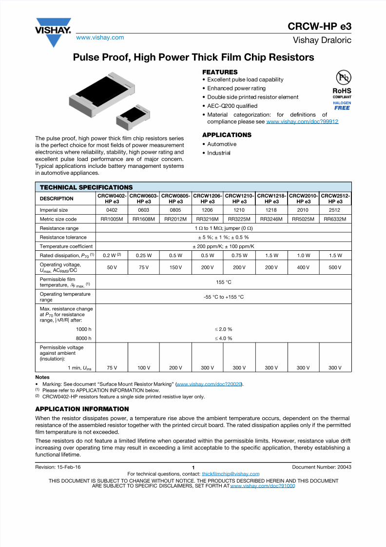
Pulse Proof, High Power Thick Film Chip Resistors
The pulse proof, high power thick film chip resistors seriesis the perfect choice for most fields of power measurementelectronics where reliability, stability, high power rating andexcellent pulse load performance are of major concern.Typical applications include battery management systemsin automotive appliances.
FEATURES
• Excellent pulse load capability
• Enhanced power rating
• Double side printed resistor element• AEC-Q200 qualified
• Material categorization: for definitions ofcompliance please see www.vishay.com/doc?99912
APPLICATIONS
• Automotive
• Industrial
Notes
• Marking: See document “Surface Mount Resistor Marking” ( www.vishay.com/doc?20020 ).(1) Please refer to APPLICATION INFORMATION below.(2) CRCW0402-HP resistors feature a single side printed resistive layer only.
APPLICATION INFORMATION
When the resistor dissipates power, a temperature rise above the ambient temperature occurs, dependent on the thermalresistance of the assembled resistor together with the printed circuit board. The rated dissipation applies only if the permittedfilm temperature is not exceeded.
These resistors do not feature a limited lifetime when operated within the permissible limits. However, resistance value driftincreasing over operating time may result in exceeding a limit acceptable to the specific application, thereby establishing afunctional lifetime.
TECHNICAL SPECIFICATIONS
DESCRIPTIONCRCW0402-
HP e3CRCW0603-
HP e3CRCW0805-
HP e3CRCW1206-
HP e3CRCW1210-
HP e3CRCW1218-
HP e3CRCW2010-
HP e3CRCW2512-
HP e3
Imperial size 0402 0603 0805 1206 1210 1218 2010 2512
Metric size code RR1005M RR1608M RR2012M RR3216M RR3225M RR3246M RR5025M RR6332M
Resistance range 1 to 1 M jumper (0 )
Resistance tolerance ± 5 %; ± 1 %; ± 0.5 %
Temperature coefficient ± 200 ppm/K; ± 100 ppm/K
Rated dissipation, P70 (1) 0.2 W (2) 0.25 W 0.5 W 0.5 W 0.75 W 1.5 W 1.0 W 1.5 W
Operating voltage, U max. ACRMS /DC
50 V 75 V 150 V 200 V 200 V 200 V 400 V 500 V
Permissible film
temperature,
F max. (1) 155 °C
Operating temperature range
-55 °C to +155 °C
Max. resistance change at P70 for resistance range, |R / R| after:
1000 h 2.0 %
8000 h 4.0 %
Permissible voltage against ambient(insulation):
1 min, U ins 75 V 100 V 200 V 300 V 300 V 300 V 300 V 300 V
8/18/2019 Vishay Dale 33ohm Resistors
http://slidepdf.com/reader/full/vishay-dale-33ohm-resistors 2/11
CRCW-HP e3www.vishay.com Vishay Draloric
Revision: 15-Feb-16 2 Document Number: 20043For technical questions, contact: [email protected]
THIS DOCUMENT IS SUBJECT TO CHANGE WITHOUT NOTICE. THE PRODUCTS DESCRIBED HEREIN AND THIS DOCUMENT ARE SUBJECT TO SPECIFIC DISCLAIMERS, SET FORTH AT www.vishay.com/doc?91000
Note
• The temperature coefficient of resistance (TCR) is not specified for 0 jumpers.
TEMPERATURE COEFFICIENT AND RESISTANCE RANGE
TYPE / SIZE TCR TOLERANCE RESISTANCE E-SERIES
CRCW0402-HP e3
± 200 ppm/K ± 5 % 1 to 1 M E24
± 100 ppm/K± 1 %
1 to 1 M E24; E96± 0.5 %
Jumper, Imax. = 3 A 10 m 0 -
CRCW0603-HP e3
± 200 ppm/K ± 5 % 1 to 1 M E24
± 100 ppm/K± 1 %
1 to 1 M E24; E96± 0.5 %
Jumper, Imax. = 5 A 8 m 0 -
CRCW0805-HP e3
± 200 ppm/K ± 5 % 1 to 1 M E24
± 100 ppm/K± 1 %
1 to 1 M E24; E96± 0.5 %
Jumper, Imax. = 6 A 5 m 0 -
CRCW1206-HP e3
± 200 ppm/K ± 5 % 1 to 1 M E24
± 100 ppm/K± 1 %
1 to 1 M E24; E96± 0.5 %
Jumper, Imax. = 10 A 5 m 0 -
CRCW1210-HP e3
± 200 ppm/K ± 5 % 1 to 1 M E24
± 100 ppm/K± 1 %
1 to 1 M E24; E96
± 0.5 %Jumper, Imax. = 12 A 4 m 0 -
CRCW1218-HP e3
± 200 ppm/K ± 5 % 1 to 1 M E24
± 100 ppm/K± 1 %
1 to 1 M E24; E96± 0.5 %
Jumper, Imax. = 20 A 4 m 0 -
CRCW2010-HP e3
± 200 ppm/K ± 5 % 1 to 1 M E24
± 100 ppm/K± 1 %
1 to 1 M E24; E96± 0.5 %
Jumper, Imax. = 12 A 5 m 0 -
CRCW2512-HP e3
± 200 ppm/K ± 5 % 1 to 1 M E24
± 100 ppm/K± 1 %
1 to 1 M E24; E96± 0.5 %
Jumper, Imax. = 16 A 5 m 0 -
PACKAGING
TYPE / SIZE CODE QUANTITY PACKAGING STYLE WIDTH PITCHPACKAGINGDIMENSIONS
CRCW0402-HP e3ED = ET7 10 000
Paper tape acc. toIEC 60286-3, Type 1a
8 mm
2 mmØ 180 mm / 7"
EE = EF4 50 000 Ø 330 mm / 13"
CRCW0603-HP e3
EI = ET2 5000
2 mm
Ø 180 mm / 7"ED = ET3 10 000 Ø 180 mm / 7"EL = ET4 20 000 Ø 285 mm / 11.25"EE = ET8 20 000 Ø 330 mm / 13"EA = ET1 5000
4 mmØ 180 mm/7"
EB = ET5 10 000 Ø 285 mm / 11.25"EC = ET6 20 000 Ø 330 mm / 13"
CRCW0805-HP e3
EA = ET1 5000
4 mm
Ø 180 mm/7"
EB = ET5 10 000 Ø 285 mm / 11.25"EC = ET6 20 000 Ø 330 mm / 13"
CRCW1206-HP e3EA = ET1 5000
4 mmØ 180 mm/7"
EB = ET5 10 000 Ø 285 mm / 11.25"EC = ET6 20 000 Ø 330 mm / 13"
CRCW1210-HP e3EA = ET1 5000
4 mmØ 180 mm/7"
EB = ET5 10 000 Ø 285 mm / 11.25"EC = ET6 20 000 Ø 330 mm / 13"
CRCW1218-HP e3 EK = ET9 4000Pressed tape acc. toIEC 60286-3, Type 1b
12 mm
4 mm Ø 180 mm/7"CRCW2010-HP e3 EF = E02 4000 4 mm Ø 180 mm/7"
CRCW2512-HP e3EG = E67 2000 8 mm
Ø 180 mm/7"EH = E82 4000 4 mm
8/18/2019 Vishay Dale 33ohm Resistors
http://slidepdf.com/reader/full/vishay-dale-33ohm-resistors 3/11
8/18/2019 Vishay Dale 33ohm Resistors
http://slidepdf.com/reader/full/vishay-dale-33ohm-resistors 4/11
CRCW-HP e3www.vishay.com Vishay Draloric
Revision: 15-Feb-16 4 Document Number: 20043For technical questions, contact: [email protected]
THIS DOCUMENT IS SUBJECT TO CHANGE WITHOUT NOTICE. THE PRODUCTS DESCRIBED HEREIN AND THIS DOCUMENT ARE SUBJECT TO SPECIFIC DISCLAIMERS, SET FORTH AT www.vishay.com/doc?91000
DESCRIPTION
Production is strictly controlled and follows an extensive setof instructions established for reproducibility. A cermet filmlayer and a glass-over are deposited on both sides of a highgrade (Al2O3 ) ceramic substrate with its prepared innercontacts on both sides. A special laser is used to achievethe target value by smoothly fine trimming the resistive layerwithout damaging the ceramics. The resistor elements arecovered by a protective coating designed for electrical,mechanical and climatic protection. The terminationsreceive a final pure tin on nickel plating. A three orfour-character code marking designates the resistancevalues in accordance with IEC 60062. The three-charactercode system is applicable to values from E24 series only,while the four-character code system is applicable to valuesfrom E96 and E24 series.
The result of the determined production is verified by anextensive testing procedure on 100 % of the individual chipresistors. Only accepted products are laid directly into the
tape in accordance with IEC 60286-3 Type 1a andType 1b (1).
ASSEMBLY
The resistors are suitable for processing on automatic SMDassembly systems. They are suitable for automaticsoldering wave, reflow or vapor phase as shown inIEC 61760-1 (1). The encapsulation is resistant to allcleaning solvents commonly used in the electronicsindustry, including alcohols, esters and aqueous solutions.The suitability of conformal coatings, potting compoundsand their processes, if applied, shall be qualified byappropriate means to ensure the long-term stability of thewhole system.
The resistors are RoHS-compliant, the pure tin platingprovides compatibility with lead (Pb)-free andlead-containing soldering processes. Solderability isspecified for 2 years after production or requalification. Thepermitted storage time is 20 years. The immunity of theplating against tin whisker growth has been proven underextensive testing.
MATERIALS
Vishay acknowledges the following systems for theregulation of hazardous substances:
• IEC 62474, Material Declaration for Products of and for theElectrotechnical Industry, with the list of declarablesubstances given therein (2)
• The Global Automotive Declarable Substance List(GADSL) (3)
• The REACH regulation (1907/2006/EC) and the related listof substances with very high concern (SVHC) (4) for itssupply chain
The products do not contain any of the bannedsubstances as per IEC 62474, GADSL, or the SVHC list,see www.vishay.com/how/leadfree.
Hence the products fully comply with the followingdirectives:
• 2000/53/EC End-of-Life Vehicle Directive (ELV) and Annex II (ELV II)
• 2011/65/EU Restriction of the Use of HazardousSubstances Directive (RoHS) with amendment2015/863/EU
• 2012/19/EU Waste Electrical and Electronic EquipmentDirective (WEEE)
Vishay pursues the elimination of conflict minerals from itssupply chain, see the Conflict Minerals Policy atwww.vishay.com/doc?49037.
APPROVALS
The resistors are qualified according to AEC-Q200. Where applicable, the resistors are tested in accordance
with EN 140401-802 which refers to EN 60115-1,EN 60115-8 and the variety of environmental testprocedures of the IEC 60068 (1) series.
RELATED PRODUCTS
For more information about products with superior surgeand pulse performance please refer to datasheet: D/CRCW-IF e3, Pulse Proof Thick Film Chip Resistorswww.vishay.com/doc?20024.
For thick film resistors with standard requirements for powerrating, please refer to datasheet: D/CRCW e3, Standard Thick Film Chip
www.vishay.com/doc?20035.For anti-surge products and high power rating, please referto datasheet: RCS e3, Anti-Surge High Power Thick Film Chip Resistorswww.vishay.com/doc?20065.
Notes(1) The quoted IEC standards are also released as EN standards with the same number and identical contents.(2) The IEC 62474 list of declarable substances is maintained in a dedicated database, which is available at http://std.iec.ch/iec62474.(3) The Global Automotive Declarable Substance List (GADSL) is maintained by the American Chemistry Council and available at
www.gadsl.org.(4) The SVHC list is maintained by the European Chemical Agency (ECHA) and available at http://echa.europa.eu/candidate-list-table.

8/18/2019 Vishay Dale 33ohm Resistors
http://slidepdf.com/reader/full/vishay-dale-33ohm-resistors 5/11
CRCW-HP e3www.vishay.com Vishay Draloric
Revision: 15-Feb-16 5 Document Number: 20043For technical questions, contact: [email protected]
THIS DOCUMENT IS SUBJECT TO CHANGE WITHOUT NOTICE. THE PRODUCTS DESCRIBED HEREIN AND THIS DOCUMENT ARE SUBJECT TO SPECIFIC DISCLAIMERS, SET FORTH AT www.vishay.com/doc?91000
FUNCTIONAL PERFORMANCE
Single Pulse
Maximum pulse load, single pulse; applicable if 0 and n < 1000 and Û Ûmax.;for permissible resistance change equivalent to 8000 h operation
Continuous Pulse
Maximum pulse load, continuous pulses; applicable if P ( amb ) and Û Ûmax.;for permissible resistance change equivalent to 8000 h operation
10
100
1000
10000
0.01
0.1
1
10
100
1000
10 000
0.000001 0.00001 0.0001 0.001 0.01 0.1 1 10 100
Axis Title
1 s t l i n e
2 n d l i n e
^
2 n d l i n e
P m a x . - P u l s e L o a d
( W )
t i - Pulse Duration (s)2nd line
2512
1218201012101206080506030402
P
10
100
1000
10000
0.01
0.1
1
10
100
1000
10 000
0.000001 0.00001 0.0001 0.001 0.01 0.1 1 10 100
Axis Title
1 s t l i n e
2 n d l i n e
^
2 n d l i n e
P m a x . -
C o n t i n u o u s P u l s e L o a d ( W )
t i - Pulse Duration (s)2nd line
25121218201012101206080506030402
P
8/18/2019 Vishay Dale 33ohm Resistors
http://slidepdf.com/reader/full/vishay-dale-33ohm-resistors 6/11
CRCW-HP e3www.vishay.com Vishay Draloric
Revision: 15-Feb-16 6 Document Number: 20043For technical questions, contact: [email protected]
THIS DOCUMENT IS SUBJECT TO CHANGE WITHOUT NOTICE. THE PRODUCTS DESCRIBED HEREIN AND THIS DOCUMENT ARE SUBJECT TO SPECIFIC DISCLAIMERS, SET FORTH AT www.vishay.com/doc?91000
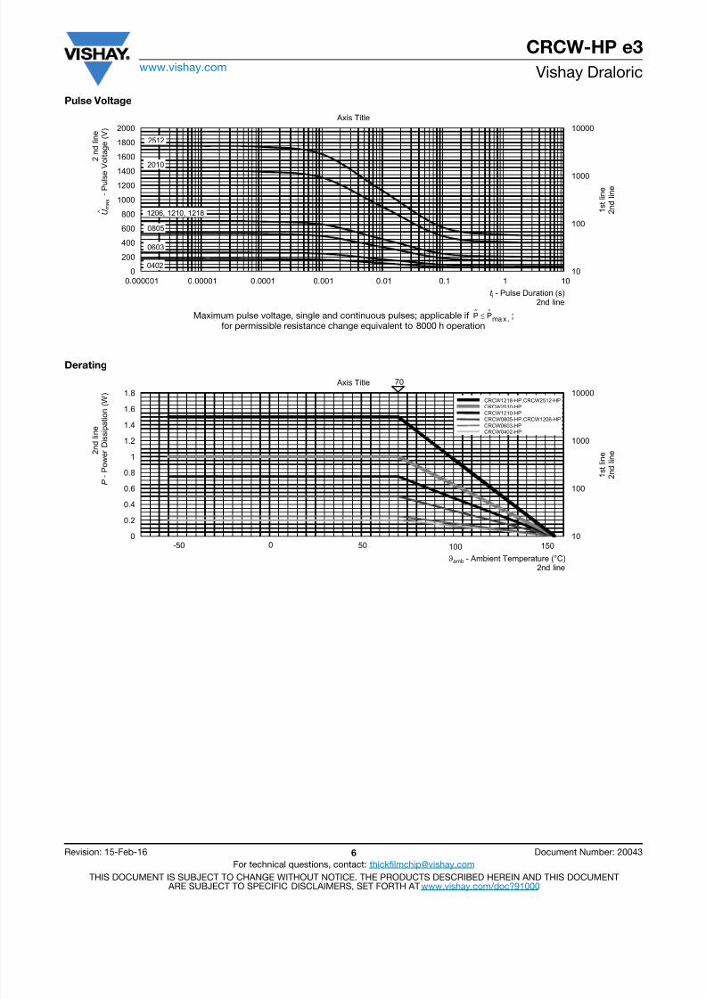
Pulse Voltage
Maximum pulse voltage, single and continuous pulses; applicable if ;for permissible resistance change equivalent to 8000 h operation
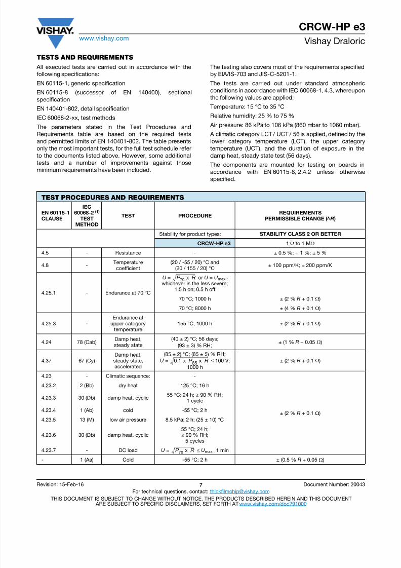
Derating
10
100
1000
10000
0
200
400
600
800
1000
12001400
1600
1800
2000
0.000001 0.00001 0.0001 0.001 0.01 0.1 1 10
Axis Title
1 s t l i n e
2 n d l i n e
^
2 n d l i n e
U m a x . - P u l s e
V o l t a g e ( V )
t i - Pulse Duration (s)2nd line
2512
1206, 1210, 1218
0805
2010
0603
0402
Pˆ Pˆma x.
10
100
1000
10000
0
0.2
0.4
0.6
0.8
1
1.2
1.4
1.6
1.8
Axis Title
1 s t l i n e
2 n d l i n e 2
n d l i n e
P - P o w e r D i s s i p a t i o n ( W )
ϑamb - Ambient Temperature (°C)2nd line
70
0 50 100 150-50
CRCW1218-HP, CRCW2512-HP
CRCW2010-HP
CRCW1210-HP
CRCW0805-HP, CRCW1206-HP
CRCW0603-HP
CRCW0402-HP
8/18/2019 Vishay Dale 33ohm Resistors
http://slidepdf.com/reader/full/vishay-dale-33ohm-resistors 7/11
CRCW-HP e3www.vishay.com Vishay Draloric
Revision: 15-Feb-16 7 Document Number: 20043For technical questions, contact: [email protected]
THIS DOCUMENT IS SUBJECT TO CHANGE WITHOUT NOTICE. THE PRODUCTS DESCRIBED HEREIN AND THIS DOCUMENT ARE SUBJECT TO SPECIFIC DISCLAIMERS, SET FORTH AT www.vishay.com/doc?91000
TESTS AND REQUIREMENTS
All executed tests are carried out in accordance with thefollowing specifications:
EN 60115-1, generic specification
EN 60115-8 (successor of EN 140400), sectional
specificationEN 140401-802, detail specification
IEC 60068-2-xx, test methods
The parameters stated in the Test Procedures andRequirements table are based on the required testsand permitted limits of EN 140401-802. The table presentsonly the most important tests, for the full test schedule referto the documents listed above. However, some additionaltests and a number of improvements against thoseminimum requirements have been included.
The testing also covers most of the requirements specifiedby EIA/IS-703 and JIS-C-5201-1.
The tests are carried out under standard atmosphericconditions in accordance with IEC 60068-1, 4.3, whereupon
the following values are applied:Temperature: 15 °C to 35 °C
Relative humidity: 25 % to 75 %
Air pressure: 86 kPa to 106 kPa (860 mbar to 1060 mbar).
A climatic category LCT / UCT / 56 is applied, defined by thelower category temperature (LCT), the upper categorytemperature (UCT), and the duration of exposure in thedamp heat, steady state test (56 days).
The components are mounted for testing on boards inaccordance with EN 60115-8, 2.4.2 unless otherwisespecified.
TEST PROCEDURES AND REQUIREMENTS
EN 60115-1
CLAUSE
IEC60068-2 (1)
TESTMETHOD
TEST PROCEDUREREQUIREMENTS
PERMISSIBLE CHANGE ( R )
Stability for product types: STABILITY CLASS 2 OR BETTER
CRCW-HP e3 1 to 1 M
4.5 - Resistance - ± 0.5 %; ± 1 %; ± 5 %
4.8 -Temperaturecoefficient
(20 / -55 / 20) °C and(20 / 155 / 20) °C
± 100 ppm/K; ± 200 ppm/K
4.25.1 - Endurance at 70 °C
U = or U = U max.;whichever is the less severe;
1.5 h on; 0.5 h off
70 °C; 1000 h ± (2 % R + 0.1 )70 °C; 8000 h ± (4 % R + 0.1 )
4.25.3 -Endurance at
upper categorytemperature
155 °C, 1000 h ± (2 % R + 0.1 )
4.24 78 (Cab)Damp heat,steady state
(40 ± 2) °C; 56 days;(93 ± 3) % RH;
± (1 % R + 0.05 )
4.37 67 (Cy)Damp heat,
steady state,accelerated
(85 ± 2) °C; (85 ± 5) % RH;U = 100 V;
1000 h± (2 % R + 0.1 )
4.23 - Climatic sequence: -
± (2 % R + 0.1 )
4.23.2 2 (Bb) dry heat 125 °C; 16 h
4.23.3 30 (Db) damp heat, cyclic55 °C; 24 h; 90 % RH;
1 cycle
4.23.4 1 (Ab) cold -55 °C; 2 h
4.23.5 13 (M) low air pressure 8.5 kPa; 2 h; (25 ± 10) °C
4.23.6 30 (Db) damp heat, cyclic55 °C; 24 h; 90 % RH;
5 cycles
4.23.7 - DC load U = U max.; 1 min
- 1 (Aa) Cold -55 °C; 2 h ± (0.5 % R + 0.05 )
P 70 x R
0.1 x P 85 x R
P 70 x R

8/18/2019 Vishay Dale 33ohm Resistors
http://slidepdf.com/reader/full/vishay-dale-33ohm-resistors 8/11
CRCW-HP e3www.vishay.com Vishay Draloric
Revision: 15-Feb-16 8 Document Number: 20043For technical questions, contact: [email protected]
THIS DOCUMENT IS SUBJECT TO CHANGE WITHOUT NOTICE. THE PRODUCTS DESCRIBED HEREIN AND THIS DOCUMENT ARE SUBJECT TO SPECIFIC DISCLAIMERS, SET FORTH AT www.vishay.com/doc?91000
Note(1) The quoted IEC standards are also released as EN standards with the same number and identical contents.
4.19 14 (Na)Rapid change of
temperature
30 min at -55 °C and30 min at 125 °C;
1000 cycles
± (1 % R + 0.05 )no visible damage
4.13 - Short time overloadU = 2.5 x 2 x U max.;
whichever is the less severe;5 s
± (2 % R + 0.05 )
4.27 -Single pulse highvoltage overload
Severity no. 4:U = 10 x or
U = 2 x U max.;whichever is the less severe;
10 pulses 10 µs/700 µs
± (1 % R + 0.05 )no visible damage
4.39 - Periodic electricoverload
U = orU
= 2 xU
max.;whichever is the less severe;0.1 s on; 2.5 s off;
1000 cycles
± (1 % R + 0.05 )no visible damage
4.38 -Electrostatic
discharge(human body model)
IEC 61340-3-1 (1);3 pos. + 3 neg. discharges;ESD voltage acc. to the size
± (1 % R + 0.05 )
4.22 6 (Fc) Vibration
Endurance by sweeping;10 Hz to 2000 Hz;
no resonance;amplitude 1.5 mm or
200 m/s2;7.5 h
± (0.5 % R + 0.05 )no visible damage
4.17 58 (Td) Solderability
Solder bath method;Sn60Pb40
non-activated flux;(235 ± 5) °C;(2 ± 0.2) s Good tinning ( 95 % covered)
no visible damageSolder bath method;Sn96.5Ag3Cu0.5
non-activated flux;(245 ± 5) °C;
(3 ± 0.3) s
4.18 58 (Td)Resistance tosoldering heat
Solder bath method(260 ± 5) °C;
(10 ± 1) s± (0.5 % R + 0.05 )
4.29 45 (XA)Component solvent
resistanceIsopropyl alcohol;+50 °C; method 2
No visible damage
4.32 21 (Uu3 ) Shear(adhesion)
CRCW0402-HP and
CRCW0603-HP: 9 N No visible damageCRCW0805-HP to
CRCW2512-HP: 45 N
4.33 21 (Uu1 ) Substrate bendingDepth 2 mm;
3 times± (0.25 % R + 0.05 )
no visible damage, no open circuit in bent position
4.7 - Voltage proof U = 1.4 x U ins; 60 s No flashover or breakdown
4.35 -Flammability,
needle flame testIEC 60695-11-5 (1);
10 sNo burning after 30 s
TEST PROCEDURES AND REQUIREMENTS
EN 60115-1 CLAUSE
IEC60068-2 (1)
TESTMETHOD
TEST PROCEDUREREQUIREMENTS
PERMISSIBLE CHANGE ( R )
Stability for product types: STABILITY CLASS 2 OR BETTERCRCW-HP e3 1 to 1 M
P 70 x R
P 70 x R
15 x P 70 x R

8/18/2019 Vishay Dale 33ohm Resistors
http://slidepdf.com/reader/full/vishay-dale-33ohm-resistors 9/11
CRCW-HP e3www.vishay.com Vishay Draloric
Revision: 15-Feb-16 9 Document Number: 20043For technical questions, contact: [email protected]
THIS DOCUMENT IS SUBJECT TO CHANGE WITHOUT NOTICE. THE PRODUCTS DESCRIBED HEREIN AND THIS DOCUMENT ARE SUBJECT TO SPECIFIC DISCLAIMERS, SET FORTH AT www.vishay.com/doc?91000
DIMENSIONS
SOLDER PAD DIMENSIONS
Notes
• The given solder pad dimensions reflect the considerations for board design and assembly as outlined e.g in standards IEC 61188-5-x (1) orin publication IPC-7351. Still, the given solder pad dimensions will be found adequate for most general applications.
(1) The quoted IEC standards are also released as EN standards with the same number and identical contents.
DIMENSIONS AND MASS
TYPEL
(mm)W
(mm)H
(mm)T1
(mm)T2
(mm)MASS(mg)
CRCW0402-HP e3 1.0 ± 0.05 0.5 ± 0.05 0.3 ± 0.10 0.25 ± 0.10 0.2 ± 0.10 0.65
CRCW0603-HP e3 1.6 ± 0.10 0.85 ± 0.10 0.45 ± 0.10 0.3 ± 0.20 0.3 ± 0.20 2
CRCW0805-HP e3 2.0 ± 0.15 1.25 ± 0.15 0.5 ± 0.10 0.4 ± 0.20 0.35 ± 0.20 5.5
CRCW1206-HP e3 3.1 ± 0.20 1.6 ± 0.15 0.5 ± 0.15 0.5 ± 0.20 0.45 ± 0.20 10
CRCW1210-HP e3 3.2 ± 0.20 2.5 ± 0.20 0.6 ± 0.10 0.45 ± 0.20 0.4 ± 0.20 18
CRCW1218-HP e3 3.1 ± 0.20 4.6 ± 0.20 0.6 ± 0.10 0.45 ± 0.20 0.4 ± 0.20 31
CRCW2010-HP e3 5.0 ± 0.15 2.5 ± 0.15 0.6 ± 0.10 0.6 ± 0.20 0.6 ± 0.20 25.5
CRCW2512-HP e3 6.3 ± 0.20 3.15 ± 0.15 0.6 ± 0.10 0.6 ± 0.20 0.6 ± 0.20 42
RECOMMENDED SOLDER PAD DIMENSIONS
TYPE
WAVE SOLDERING REFLOW SOLDERING
G(mm)
Y (mm)
X (mm)
Z(mm)
G(mm)
Y (mm)
X (mm)
Z(mm)
CRCW0402-HP e3 - - - - 0.45 0.6 0.6 1.65
CRCW0603-HP e3 0.65 1.10 1.25 2.85 0.75 0.75 1.00 2.25
CRCW0805-HP e3 0.90 1.30 1.60 3.50 1.00 0.95 1.45 2.90
CRCW1206-HP e3 1.40 1.40 1.95 4.20 1.50 1.05 1.8 3.60
CRCW1210-HP e3 1.80 1.45 2.95 4.70 1.70 1.10 2.80 4.90
CRCW1218-HP e3 1.60 1.50 5.10 4.60 1.70 1.10 4.90 4.90
CRCW2010-HP e3 3.60 1.65 2.85 6.90 3.70 1.20 2.70 6.10
CRCW2512-HP e3 4.90 1.60 3.50 8.10 5.00 1.25 3.35 7.50
G X
YZ
8/18/2019 Vishay Dale 33ohm Resistors
http://slidepdf.com/reader/full/vishay-dale-33ohm-resistors 10/11
Legal Disclaimer Noticewww.vishay.com Vishay
Revision: 02-Oct-12 1 Document Number: 91000
Disclaimer
ALL PRODUCT, PRODUCT SPECIFICATIONS AND DATA ARE SUBJECT TO CHANGE WITHOUT NOTICE TO IMPROVE
RELIABILITY, FUNCTION OR DESIGN OR OTHERWISE.
Vishay Intertechnology, Inc., its affiliates, agents, and employees, and all persons acting on its or their behalf (collectively,“Vishay”), disclaim any and all liability for any errors, inaccuracies or incompleteness contained in any datasheet or in any other
disclosure relating to any product.
Vishay makes no warranty, representation or guarantee regarding the suitability of the products for any particular purpose or
the continuing production of any product. To the maximum extent permitted by applicable law, Vishay disclaims (i) any and all
liability arising out of the application or use of any product, (ii) any and all liability, including without limitation special,
consequential or incidental damages, and (iii) any and all implied warranties, including warranties of fitness for particular
purpose, non-infringement and merchantability.
Statements regarding the suitability of products for certain types of applications are based on Vishay’s knowledge of typical
requirements that are often placed on Vishay products in generic applications. Such statements are not binding statements
about the suitability of products for a particular application. It is the customer’s responsibility to validate that a particular
product with the properties described in the product specification is suitable for use in a particular application. Parameters
provided in datasheets and/or specifications may vary in different applications and performance may vary over time. All
operating parameters, including typical parameters, must be validated for each customer application by the customer’s
technical experts. Product specifications do not expand or otherwise modify Vishay’s terms and conditions of purchase,
including but not limited to the warranty expressed therein.
Except as expressly indicated in writing, Vishay products are not designed for use in medical, life-saving, or life-sustaining
applications or for any other application in which the failure of the Vishay product could result in personal injury or death.
Customers using or selling Vishay products not expressly indicated for use in such applications do so at their own risk. Please
contact authorized Vishay personnel to obtain written terms and conditions regarding products designed for such applications.
No license, express or implied, by estoppel or otherwise, to any intellectual property rights is granted by this document or by
any conduct of Vishay. Product names and markings noted herein may be trademarks of their respective owners.
Material Category Policy Vishay Intertechnology, Inc. hereby certifies that all its products that are identified as RoHS-Compliant fulfill the
definitions and restrictions defined under Directive 2011/65/EU of The European Parliament and of the Council
of June 8, 2011 on the restriction of the use of certain hazardous substances in electrical and electronic equipment
(EEE) - recast, unless otherwise specified as non-compliant.
Please note that some Vishay documentation may still make reference to RoHS Directive 2002/95/EC. We confirm that
all the products identified as being compliant to Directive 2002/95/EC conform to Directive 2011/65/EU.
Vishay Intertechnology, Inc. hereby certifies that all its products that are identified as Halogen-Free follow Halogen-Free
requirements as per JEDEC JS709A standards. Please note that some Vishay documentation may still make reference
to the IEC 61249-2-21 definition. We confirm that all the products identified as being compliant to IEC 61249-2-21
conform to JEDEC JS709A standards.
8/18/2019 Vishay Dale 33ohm Resistors
http://slidepdf.com/reader/full/vishay-dale-33ohm-resistors 11/11
Mouser Electronics
Authorized Distributor
Click to View Pricing, Inventory, Delivery & Lifecycle Information:
Vishay:
CRCW12062K00FKEAHP CRCW120610K0FKEAHP CRCW201010R0FKEFHP CRCW1206100KFKEAHP
CRCW120615K0FKEAHP CRCW12061R00JNEAHP CRCW120610R0FKEAHP CRCW12061K00FKEAHP
CRCW04020000Z0EDHP CRCW06030000Z0EAHP CRCW12060000Z0EAHP CRCW08050000Z0EAHP
CRCW0603100KFKEAHP CRCW121012R0JNEAHP CRCW1210510RJNEAHP CRCW1210240RJNEAHP
CRCW12103K30FKEAHP CRCW1210750RFKEAHP CRCW1210150RFKEAHP CRCW06032M49DHEAP
CRCW04021K00FKEDHP CRCW040210K0FKEDHP CRCW060310K0FKEAHP CRCW06031K00FKEAHP
CRCW08051K00FKEAHP CRCW080510K0FKEAHP CRCW251210R0FKEGHP CRCW2512100RFKEGHP
CRCW201010K0FKEFHP CRCW2010100RFKEFHP CRCW20101K00FKEFHP CRCW25121K00FKEGHP
CRCW080520K0FKEAHP CRCW20102K21FKEFHP CRCW08051R00FKEAHP CRCW080515R0FKEAHP
CRCW12061R00FKEAHP CRCW0402100KFKEDHP CRCW0402100KJNEDHP CRCW0402100RFKEDHP
CRCW0402100RJNEDHP CRCW040210K0JNEDHP CRCW040210R0FKEDHP CRCW040210R0JNEDHP
CRCW040215K0FKEDHP CRCW04021K00JNEDHP CRCW04021K50FKEDHP CRCW04021M00FKEDHP
CRCW04021M00JNEDHP CRCW04021R00FKEDHP CRCW04021R00JNEDHP CRCW040220K0FKEDHP
CRCW0402220KJNEDHP
CRCW0402220RJNEDHP
CRCW040222K0JNEDHP
CRCW040222R0FKEDHP
CRCW040222R0JNEDHP CRCW040222R1FKEDHP CRCW04022K00FKEDHP CRCW04022K20JNEDHP
CRCW04022R20JNEDHP CRCW040233R0FKEDHP CRCW040233R2FKEDHP CRCW0402470KJNEDHP
CRCW0402470RJNEDHP CRCW040247K0FKEDHP CRCW040247K0JNEDHP CRCW040247R0JNEDHP
CRCW0402499RFKEDHP CRCW040249K9FKEDHP CRCW040249R9FKEDHP CRCW04024K70FKEDHP
CRCW04024K70JNEDHP CRCW04024K75FKEDHP CRCW04024K99FKEDHP CRCW04024R70JNEDHP
CRCW040275R0FKEDHP CRCW0603100KJNEAHP CRCW0603100RFKEAHP CRCW0603100RJNEAHP
CRCW060310K0JNEAHP CRCW060310R0FKEAHP CRCW060310R0JNEAHP CRCW060315K0FKEAHP
CRCW06031K00JNEAHP CRCW06031K50FKEAHP CRCW06031M00FKEAHP CRCW06031M00JNEAHP
CRCW06031R00FKEAHP CRCW06031R00JNEAHP CRCW060320K0FKEAHP CRCW0603220KJNEAHP
CRCW0603220RJNEAHP CRCW060322K0JNEAHP CRCW060322R0JNEAHP CRCW06032K00FKEAHP
CRCW06032K20JNEAHP CRCW06032R20JNEAHP CRCW060330K9FKEAHP CRCW060333R0FKEAHP