water transport in pem fuel cells - energy · 2007-03-13 · water transport in pem fuel cells:...
TRANSCRIPT

Water Transport in PEM Fuel Cells: Advanced Modeling, Material Selection, Testing,
and Design Optimization
J. Vernon Cole and Ashok GidwaniCFDRC
Prepared for:DOE Hydrogen Fuel Cell Kickoff Meeting
February 13, 2007
This presentation does not contain any proprietary or confidential information.

Background
Water Management Issues Arise From: � Generation of water by cathodic reaction � Membrane humidification requirements � Capillary pressure driven transport through porous MEA
and GDL materials � Scaling bipolar plate channel dimensions
J.H. Nam and M. Kaviany, Int. J. Heat Mass Transfer, 46, pp. 4595-4611 (2003)
Relevant Barriers and Targets
� Improved Gas Diffusion Layer, Flow Fields, Membrane Electrode Assemblies Needed to Improve Water Management: • Flooding blocks reactant transport • Drying out of membrane reduces protonic conductivity • Water distribution at shutdown, and transport during start-up, affects
transient response, cold-start capability, and materials requirements for freeze-thaw cycle robustness
� Water management improvements are needed to maintain advances in transient response and cold start-up time, while improving power performance (650 W/L power density by 2010)

Program Objectives
� Develop advanced physical models and conduct material and cell characterization experiments to improve andoptimize fuel cell design and operation;
� Demonstrate improvements in water management resultingin improved efficiency during automotive drive cycles, freeze/thaw cycle tolerance, and faster cold startup;
� Improve understanding of the effect of various cellcomponent properties and structure on the gas and water transport in a PEM fuel cell, particularly the gas diffusionmedia (GDM) and flow channels; and
� Encapsulate the developed models in a commercial modeling and analysis tool, allowing transfer of technology to the industry for future applications.

Approach
� Overall: • Integrated experimental characterization and model development • Systematically address each of the component regions of the cell • Integrate the developed advanced modeling capabilities into an analysis tool
capable of addressing water transport issues in future generation cell designs
� Modeling Approach: • Develop advanced models for water transport, and model parameters, in cell
component materials • Evaluate, and verify the developed models and parameters in a CFD based
simulation tool for unit cell performance simulation • Apply verified modeling capabilities and simulation results to devise and screen
cell and stack performance improvement approaches
� Experimental Approach: • Perform ex-situ materials characterization to support and guide model
development • Gather in-situ diagnostics for model test and verification • Characterize cell flooding sensitivity to materials and operating strategies • Implement and test performance improvement strategies

CFDRC Prior Work: Example Case
� 50 cm2 fuel cell with 4 serpentine channels �
InletOutlet
Inlet Separators (Ribs)
Dimensions of various layers: Diffusion Layer ~ 230 microns Catalyst Layer ~ 20 microns Membrane ~ 50 microns
Three-dimensional model, ~ 1.4 million grid cells Flow Flow
Flow Channels
Cell Dimensions: Channel depth ~ 1.016 mmLength and Width ~ 6.9 cm Channel width ~ 0.7874 mm

CFDRC Prior Work: Sample Results
� Operating conditions: 100% relative humidity, 80°C, 1 atm pressure, Vcell = 0.225 V
� Distributions of current density (membrane mid-section) and liquid water saturation (cathode catalyst layer midsection):
Current Density, A/m2 3.0x10⁴
Liquid Water Saturation 1.0
8.0x10² 0.0
High Inlet Humidity at Low Cell Voltages Results in Larger Quantities of Liquid Saturation and Cell Flooding

Model Testing at Ballard Independent comparison to cell diagnostic data:
MEA Water Distribution – Current Distribution High Current Conditions
1
l Pol ( )
0
1
2
3
4
5
6
7
/
l l )
0.5
0.6
0.7
0.8
0.9
1.1
1.2
A/cm
2 CFD Expt
y. Exptl
Wat
er (m
gcm
2)
CFD ExptPo y. (Exptl
1 2 3 4 5 6 7 8 9 10 11 12 13 14 15 16 1 2 3 4 5 6 7 8 9 10 11 12 13 14 15 16
Puck# Puck#
� High current prediction is adequate on average, but local current distribution errors are high.
� Predictions are poor at low current densities (needed for automotive drive cycles) and are the subject of ongoing improvement.
� Breakdown of MEA water into GDLs and membrane is not accurate � Modeling and design of the MEA water distribution is critical to cell
durability and freeze start capability

Work Schedule and Milestones April 1, 2007
� •
� •
� •
•
� Model Test/Validate • Single and Multi-Component LBM •
application / need for model andparameter improvements / optionalmodels
� Optimization and Demonstration • Deliver demonstration Stack
Estimated Start Date:
Ex-Situ Characterization: Baseline material properties
Cell and Stack Characterization Initial data delivery
Model Development: Physical models down-selected and implemented
LBM coded and ready for test
Establish confidence levels for

Key Decision Points
� Cell Scale Model Development: • FY07 Q3 (Jun 2007): Down-select basic transport model formulation • FY09 Q1 (Dec 2008): Go/NoGo Decision for improving/extending
membrane water transport and electrochemical kinetics based on outcome of steady-state and initial transient testing
� LBM Model Development: • FY08 Q2 (Mar 2008): Go/NoGo for continued development and
extension to multi-component • FY08 Q4 (Sep 2008): Go/NoGo for continued activity (begin
application)
� Design/Operational/Materials Improvement: • FY09 Q2 (Mar 2009): Select (3) candidate strategies for additional
screening via simulation and additional experiments

Project Management
Vernon Cole – Program Manager
Ashok Gidwani – Principal Investigator
Advisory Committee
Ashok Singhal – CFDRC
John Kenna – Ballard
Greg Jackson – U. Maryland
DOE Program MonitorsNancy L. Garland
Reginald Tyler
Material Charact., Ex-Situ Expts.SGL Carbon
Research Triangle Institute
Ballard Power Systems
Univ TBD
In-Situ Cell Expts.
BCS Fuel Cells
Ballard
Numerical Model Dev.CFDRC
ESI Group
Ballard
Model Validation Design ImprovementsCFDRC
BCS
RTI
SGL
CFDRC
ESI
Ballard
Organization
Project ManagementDOE Program Monitors
Research Triangle Institute
Ballard Power Systems
Univ TBD
Ballard
Numerical Model Dev. CFDRC
ESI Group
Ballard
Model Validation Design Improvements CFDRC
BCS
RTI
SGL
CFDRC
ESI
Ballard
Vernon Cole – Program Manager
Ashok Gidwani – Principal Investigator
Advisory Committee
Ashok Singhal – CFDRC
John Kenna – Ballard
Greg Jackson – U. Maryland
Nancy L. Garland
Reginald Tyler
Material Charact., Ex-Situ Expts. SGL Carbon
In-Situ Cell Expts.
BCS Fuel Cells

Budget Summary
By Fiscal Year:
FY07 FY08 FY09 FY10 FY11 DOE Cost, $K 591 1,184 1,181 1,153 565 Cost Shared, $K 170 340 340 340 170 Total Budget, $K 761 1,524 1,521 1,493 735
� Total Budget $6.03M, � DOE Funding $4.7M, � 22% of costs shared by team
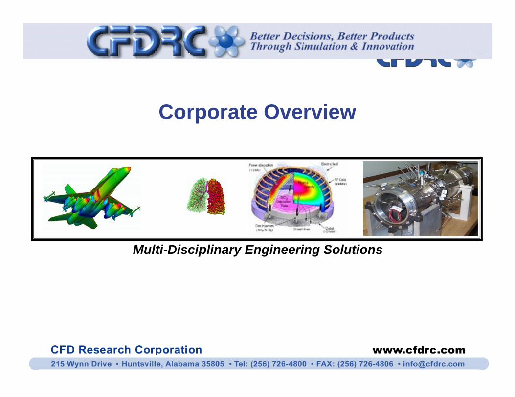
Corporate Overview
Multi-Disciplinary Engineering Solutions
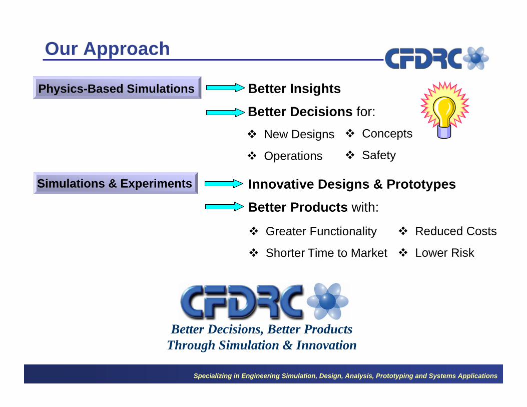
Better Insights
Better Decisions for: � New Designs � Concepts
� Operations � Safety
Our Approach
Physics-Based Simulations
Innovative Designs & Prototypes
Better Products with:
� Greater Functionality � Reduced Costs
� Shorter Time to Market � Lower Risk
Simulations & Experiments
Better Decisions, Better ProductsThrough Simulation & Innovation
Specializing in Engineering Simulation, Design, Analysis, Prototyping and Systems Applications

1987
CFDRC REVENUE ($M)
Track Record QUALIFIED PERSONNEL 16
PhD MSC 14
12 55% 20% 10
8
6
Other 4
25% 2
0
Over 25 Patents (For Licensing and Customization)
1990
1993
1996
1999
2002
2005
Spacer Metered Dose Inhaler Synthetic Microvascular
Networks Constant Volume
Rocket Motor High Energy Hypergolic
Bipropellant Gels
Cell Sorter
tip clot tip
Thrombectomy Catheter Electrostatic Air Sampler Dielectrophoresis
tube
wall of blood vessel
Microfluidic Mixing and Cleaning
Specializing in Engineering Simulation, Design, Analysis, Prototyping and Systems Applications