先端炭素材の調製と応用 - 九州大学(kyushu
TRANSCRIPT

先端炭素材の調製と応用
1.バインダー、ニードルコークス
2.Li-ion電池用負極材
3.ピッチ系炭素繊維
4.活性炭及び活性炭素繊維
九州大学先導物質化学研究所、教授
尹 聖昊
2013年9月27日
炭素資源学特論Ⅳ-1
1
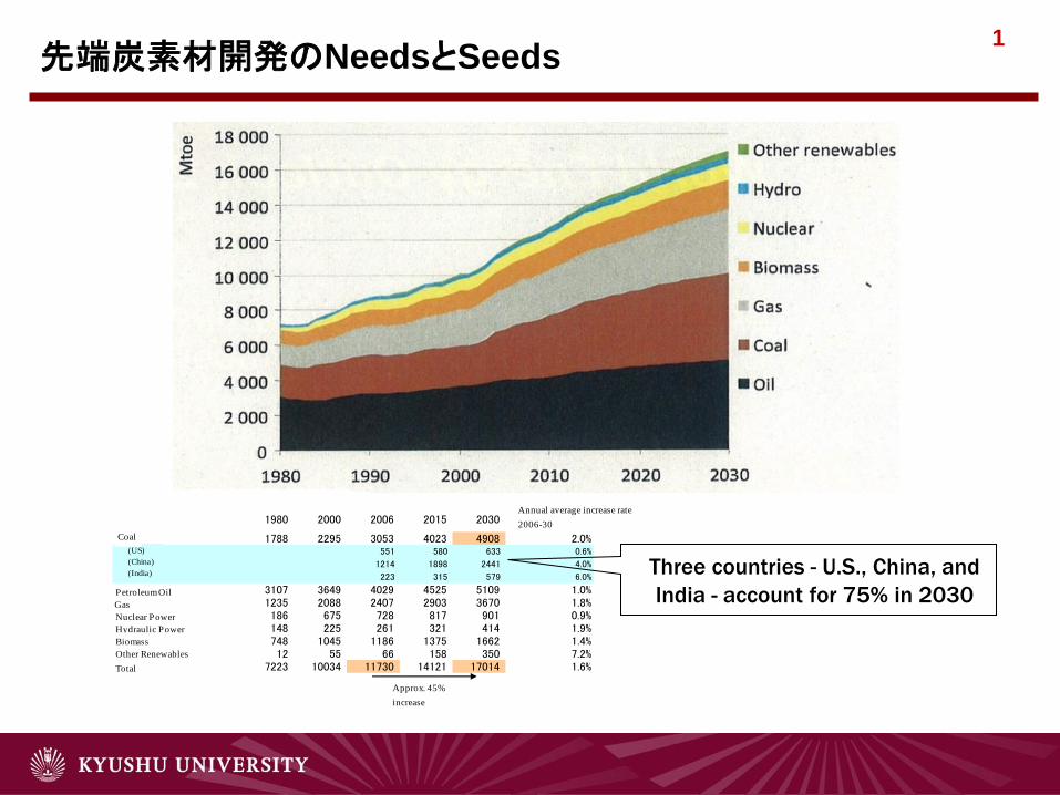
世界の一次エネルギー需要見通し(Mtoe)
1980 2000 2006 2015 2030年平均増加率
2006-30石炭 1788 2295 3053 4023 4908 2.0% (米国) 551 580 633 0.6%
(中国) 1214 1898 2441 4.0%
(インド) 223 315 579 6.0%
石油 3107 3649 4029 4525 5109 1.0%ガス 1235 2088 2407 2903 3670 1.8%原子力 186 675 728 817 901 0.9%水力 148 225 261 321 414 1.9%バイオマス 748 1045 1186 1375 1662 1.4%他の再生可能エネルギー 12 55 66 158 350 7.2%合計 7223 10034 11730 14121 17014 1.6%
約45%増加
Outlook of Global Demand for Primary EnergyAnnual average increase rate
2006-30
Approx. 45%
increase
(US)
(China)
(India)
Coal
Petroleum Oil
Gas
Nuclear Power
Hydraulic Power
Biomass
Other Renewables
Total
Three countries - U.S., China, and
India - account for 75% in 2030
Outlook of Total Production of Energy Sources 先端炭素材開発のNeedsとSeeds

2
2
Energy Demand and Supply in 21st Century
•Marked Increase of Energy Demand in Asia and Africa in 21st Century
Population x Demand/Head
Three to Four Times of Current Demands of Fossil Fuels ⇒ Increasing By-products of Fossil Fuels
Issues
◩ Supply
◩ CO2 Emission Enhances Global Warming
◩ Effective utilization of by-products of fossil fuels
先端炭素材開発のNeedsとSeeds

3
Raw materials and precursors for carbons
Coal tar
Polymer: Thermosetting and thermoplastic
Heavy oil and residues
Biomass
Raw materials
• Pitches: CF, ACF, MCMB, Ball type AC, Binder pitch, Additives
• Polymer: AC, ACF, Glassy carbon, CF
• Cokes: Electrode, Capacitor, Battery anode, AC, Additives
• Char: AC, Additives, Reducer for Solar cell
Precursor
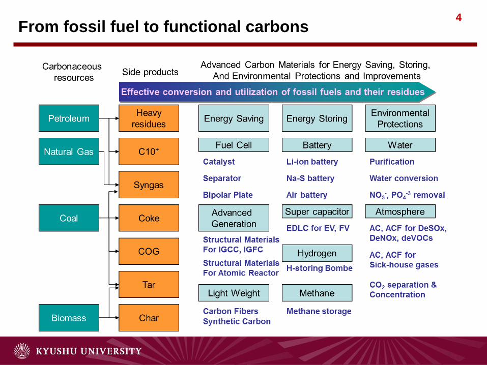
4 From fossil fuel to functional carbons

5
Electric and Heat Conductions
Conductor and Semi-conductor
Energy Storage
Battery anode
Super capacitor
Gas storage
Environmental Protection
Activated surface
Mechanical
Reinforcement
High Temperature
Materials
Allotropes
Fullerene
Bucky Onions Toroidal Structures
Nanotubes
Acetylene Blacks
Hexagonal graphite
Poly-
crystallin
e
Graphite Carbon Black
Cokes and
Activated
Carbons Carbon Fibers
Pyrocarbons
Carbyne SP1
SP2
SP2+
Cubic diamond Diamond-like Carbon SP3
rehybridization
Bonding
Hybridization Derived and Defective Forms
Ref.) Bourrat, X. Structure in Carbons and Carbon
Artifacts. In: Sciences of Carbon Materials. Marsh, H.;
Rodriguez-Reinoso, F., Eds., Universidad de Alicante,
2000. pp1-97.
Carbon Isotopes

6
0.001GPは10気圧に相当する
炭素の状態図

7
相 固体
融点 3823 K
(3550 ℃)
沸点 5073 K
(4800 °C,)
気化熱 355.8 kJ·mol−1
音の伝わる速さ 18350 m·s−1 (293.15 K)
炭素の物理特性

8 黒鉛の化学反応性
9
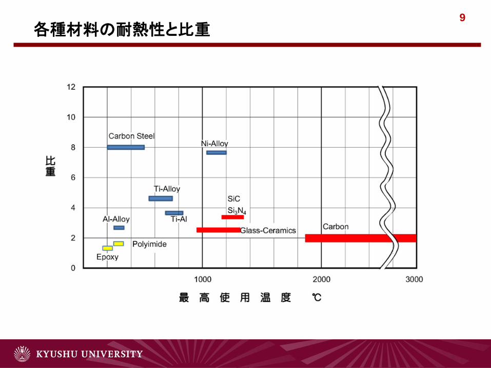
各種材料の耐熱性と比重

10
炭素化反応
炭素の生成反応

11 炭素の生成(固・液相)

12
プロセス 原 料 炭 素 材 料 特 徴
気相炭化 揮発性有機物 カーボンブラック
熱分解炭素
カーボンホイスカー
超微粒
高配向性
高強度、高電導性、高弾性
液相炭化 溶融溶解性有機物、溶融性石炭
コークス
人造黒鉛
高密度等方性黒鉛
高異方牲
高異方牲、高電導性
等方性、高密度
固相炭化 不融性繊維状有機物
熱硬化性高分子
木材、非溶融性石炭
炭素繊維
ガラス状炭素
活性炭
モレキュラーシーブカーボン
高強度、高弾性
高強度、ガス不適過
多孔性、吸着
分子ふるい
炭素化プロセスと特徴

13
T. Bairdモデル; (a)→(b)→(c)の順に成長
VGCF、CNTの成長モデル
14
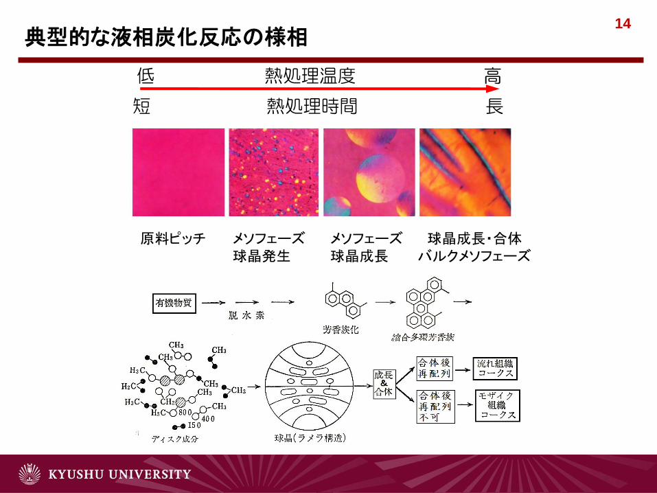
低 熱処理温度 高
短 熱処理時間 長
典型的な液相炭化反応の様相
原料ピッチ メソフェーズ
球晶発生
メソフェーズ
球晶成長
球晶成長・合体
バルクメソフェーズ

15 固相炭化の原料となる高分子

16
炭素の構造
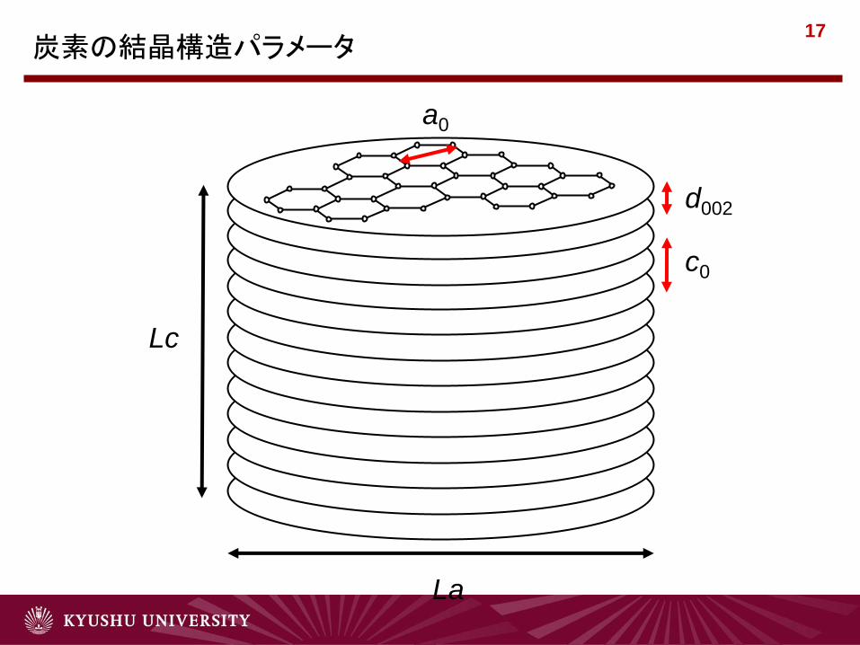
17
La
Lc
a0
c0
d002
炭素の結晶構造パラメータ

18
(002)面とd(002)
結晶面と面間隔の関係
(110)面とd(110)
(112)面とd(112)

19 有機物の加熱による変化
黒鉛化過程 前駆体生成過程 炭素化過程
前期 後期
H2O, CO2, CH4, H2
低分子
生成物
1000℃ 1500℃ 3000℃ 500℃
炭
素 黒
鉛
前駆体
分解
芳香族化
重縮合
構造再編
黒鉛構造発達
共役系
拡大
組織の
緻密化
焼成工程 黒鉛化工程

20
熱処理温度による結晶構造変化
黒鉛

21 Nanoscopic Structure of PAN Based CF
“Structural comparison of mesophase and PAN based carbon fibers”
S.H. Hong, S. H. Yoon, I. Mochida J. Material Sci., in press (2011)

22
22
STM images of ACFs
OG7A-800H OG20A-800H
In order to remove oxygen containing functional groups for removing the heterogeneous effect of STM,
OG7A and OG20A were heat-treated at 800OC in a hydrogen atmosphere ( H2 / He =1/4).
Vacant spaces between the two domains of OG20A are larger than that of OG7A.
Domain size of OG20A is a little smaller than that of OG7A.
Slit type pores were observed in domains of OG7A and OG20A.
It can be presumed that almost pores larger than 2nm nucleated by the inter-particle
mechanism.
5nm 5nm 25nm 25nm
Slit shaped pore
(Intra-particle)
Slit shaped pore
(Intra-particle)
Channeling
pore
(Inter-particles)
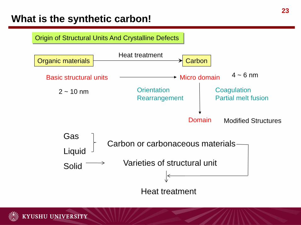
23
Gas
Liquid
Solid
Carbon or carbonaceous materials
Varieties of structural unit
Heat treatment
What is the synthetic carbon!
Organic materials Carbon
Basic structural units Micro domain
Domain
Orientation
Rearrangement
Coagulation
Partial melt fusion
Modified Structures
Heat treatment
2 ~ 10 nm
4 ~ 6 nm
Origin of Structural Units And Crystalline Defects

IAMS, Kyushu University
Lc(002)
Aromatic planar molecule
Stacking unit of planar molecules
(Molecular assemble unit)
Micro-domain
(Quasi-aligned molecular assemble unit)
Domain
Closely packed micro-
domains in mesophase
pitch
Heat
Treatment
Graphitic unit
Pleat unit
Aligned micro-domains in
the mesophase pitch fiber
fiber axis
Deformed micro-domain
Pitch fiber Graphitized fiber
spinning
“Axial nano-scale microstructure in the graphitized fiber inherited from liquid crystal mesophase pitch” Carbon, 34, 83-88 (1996) S. H. Yoon, Y. Korai, K.Yokogawa, S. Fukuyama, M. Yoshimura, I. Mochida
Basic structure and structural control of carbon

25
Understanding carbon structures:Carbon nano-world
Structures • Structural units
• Nano-phased units
Spaces • Pore size
and homogeneity
• Pore amounts
Surfaces • Edges
(Kinds and amounts)
• Basals
(Perfectness and
Orientation)
+
Nano
Syntheses
→
Mass-
production
Controls
→
Improving Performances
and
Functions
Hybridization
→ Improving
Performances
and
Functions
→
Creating
New
Functions
High
performances
High
functions
New
functions
Applications Productions

26
Electric and Heat Conductions
Conductor and Semi-conductor
Energy Storage
Battery anode
Super capacitor
Gas storage
Environmental Protection
Activated surface
Mechanical
Reinforcement
High Temperature
Materials
炭素の応用

27
Carbon Fiber

28 Battery, Capacitor, Atomic and Coal Power Plants

29
Graphite Electrode

30 単結晶シリコン引上げ用CZ炉

31
高温工学試験研究炉(HTTR)
出典:日本原子力研究開発機構 HP

32 臨界プラズマ(核融合)試験装置JT-60
提供:日本原子力研究開発機構

33 医療用 X線CTスキャナ

34 Air Purification Using ACF (Remote Watching System)
炭素材の製造
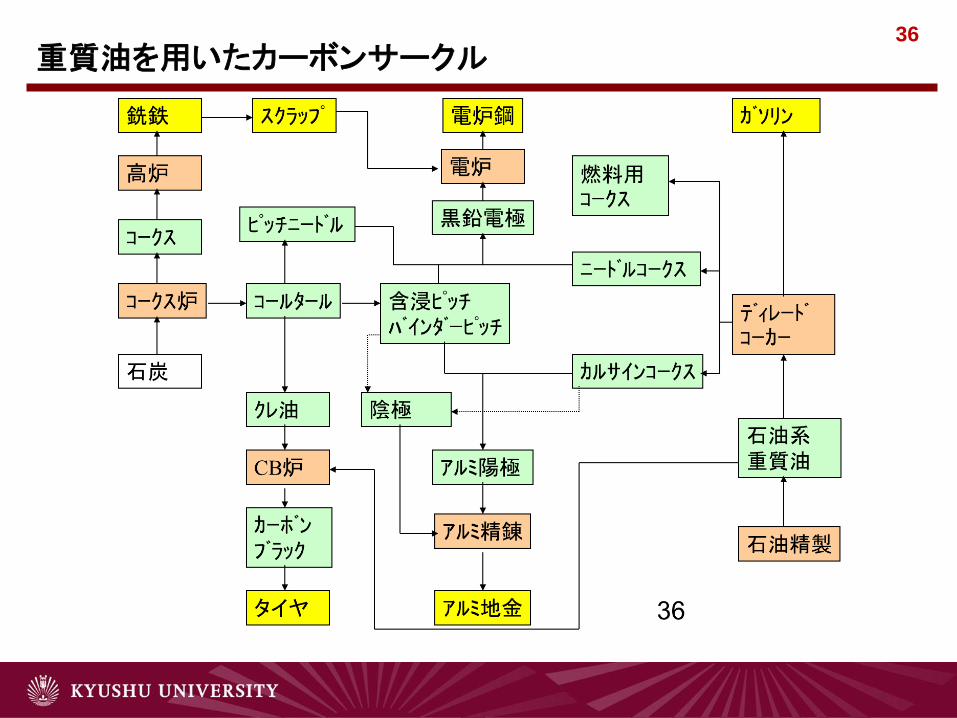
36
重質油を用いたカーボンサークル

37 重質油又は石炭残渣を用いた炭素材の製造模式図

38
Mixing
Forming
Baking
Binder
Pitch
Crushing
Storage bins
Machining Finished
product
Graphitization
Classified
Fractions
Screening
Silos
Anthracite Graphite Coke
Weighing
Pitch
Impregnation
Grinding
黒鉛電極の製造

39
等方性黒鉛の製造工程(二元系原料)

40 先端炭素材の製造におけるポイント
High performance pitch based carbon fibers: less than 50
ppm
Capacitor : less than 500 ppm
High performance needle coke : 500 ppm
Carbon medicines: less than 300 ppm?
Carbon anode for LIB: less than 100 ppm
…

41 コールタールピッチのQI 除去
Method Principle Advantage Disadvantage
① Filtering
(Heat, Solvent)
Decreasing viscosity by heating or
solution
Mesh filtering of QI
Only QI Removal
No heavy fraction removal Large equipment X
② Centrifuging
(Heat, Solvent)
Decreasing viscosity by heating or
solution
Centrifugal condensing of QI
Only QI Removal
No heavy fraction removal Large equipment X
③ Solvent -
Precipitation
Mixing of miscible solvents
Precipitation removal of QI Low productivity
④ Non-solvent
Precipitation
Mixing of non-miscible solvents
Precipitation removal of QI Large equipment OK Heavy fraction removal
• It is relatively easy to remove QI in lab scale.
• QI removal in the industrial scale
Very difficult to remove finely dispersed QI from large amount of viscous liquid
Only success in Japan
Japan several ten thousands ~ hundreds tons/year scale

ピッチ系炭素繊維

43 Needs and Seeds of Carbon Fiber
High Performance Carbon Fiber(HPCF) : CF with TS over 3500MPa
- CFRP for lightening :
Transportation: Aerospace (B787, A380,…), Military, EV (EV, HEV,
FEV: Parts need special properties/performances)
Sports, Robotics, …
Energy Devices: Windmill, …
Construction: CFRC, Supplement
Middle Performance Carbon Fiber(MPCF) : CF with TS of 1500~3500MPa
- CFRP Application: CF with TS of 1500~3500MPa, Long Fiber
Transportation: Main Body for EV (EV, HEV, FEV)
Construction (Short Fiber CFRC)
Low Performance Carbon Fiber(LPCF) : CF with TS Less Than 1200 MPa
- Refractory Materials for High Temperature Devices (Short Fiber)
- ACF for Environmental Protections
Strong demand of MPCF with appropriate mechanical properties and
production cost for broadening novel market;
Pitch Based Carbon Fiber Can Meet of the Carbon Fiber.
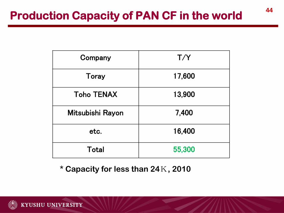
44 Production Capacity of PAN CF in the world
Company T/Y
Toray 17,600
Toho TENAX 13,900
Mitsubishi Rayon 7,400
etc. 16,400
Total 55,300
* Capacity for less than 24K, 2010

45 Current State Production Capacity of Pitch Based CF
Company T/Y Type Precursor Pitch
Kureha 1450 Short Isotropic
Osaka Gas Chemical 600 Short Isotropic
Mitsubishi Chemical 1000 Long Mesophase
Japan Graphite Fiber 180 Long Mesophase
CYTEC 230 Long Mesophase
Total 3460
* 2010, (From HP Information, China: 200T/Y, Isotropic)
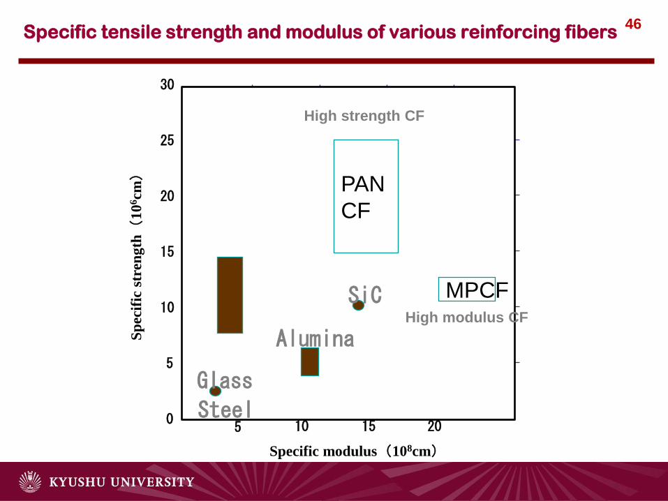
46 Specific tensile strength and modulus of various reinforcing fibers
0
5
10
15
20
25
30
5 10 15 20
Sp
ecif
ic s
tren
gth(
10
6cm
)
Specific modulus(108cm)
PAN
CF
MPCF SiC
Steel
Alumina Glass
High modulus CF
High strength CF

47 Relationship between TS & YM before Improving
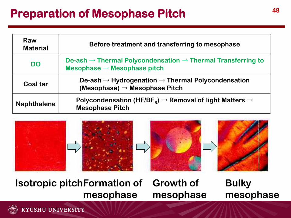
48 Preparation of Mesophase Pitch
Raw
Material Before treatment and transferring to mesophase
DO De-ash → Thermal Polycondensation → Thermal Transferring to
Mesophase → Mesophase pitch
Coal tar De-ash → Hydrogenation → Thermal Polycondensation
(Mesophase) → Mesophase Pitch
Naphthalene Polycondensation (HF/BF3) → Removal of light Matters →
Mesophase Pitch
Isotropic pitch Formation of
mesophase
Growth of
mesophase
Bulky
mesophase

49 MPCF Production Processes
紡糸用ピッチ
溶融紡糸 不 融 化酸化反応
炭 化窒素下
黒 鉛 化窒素下
O
OHO
HO CC
CC
CC
C CC
ピッチ
ポンプ
ノズル
M 押出機
Smaller Impurities
Pitch with easy orientation property
Increasing Graphitic Units
Higher orientation
Higher Strength
&
Modulus
Higher Modulus
Mesophase
Pitch
Melt
Spinning Stabilization
Carbonization
(N2)
Graphitization
(N2)
Pitch
Hopper
Extruder
Nozzle

50
Fig. Correlation between fiber diameter
and spinning viscosity
7
8
9
10
11
12
13
0 50 100 150 200 250
Spinning viscosity (Pa・s)
Fib
er
dia
mete
r (μ
m)
DO2-400
DO2-380
Fig. Spinning apparatus
Pressurized by Nitrogen
M
heater
filter
pitch
spinneret
winder

51 Stabilization of Pitch Fibers
Oxidation
Oxygen
Heat
by-product gas
H2,H2O,CO2,etc
Polymerization

52 Increasing Tensile Strength by Removal of Inorganic Impurities
1000
1500
2000
2500
3000
3500
4000
800 1200 1600 2000 2400 2800
Heat
tre
atm
ent te
mp.
,℃
Tensile strength, MPa
30ppm
270ppm
SEM
CF Cross section
after Polishing
Fig. Observation of void defect 30ppm 270ppm
SiO2 + C → SiC + CO2
Over 1250 oC
SiC → Si + C
Nucleation of voids
Over 1800 oC
Fig. Relationship between the tensile strength
and heat treatment temperature

53 Relationship between TS & YM of Recent CFs
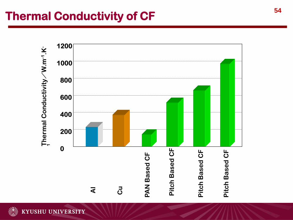
54 Thermal Conductivity of CF
1200
1000
800
600
400
200
0
Th
erm
al
Co
nd
uc
tiv
ity/
W.m
-1.K
-
1
Al
Cu
PA
N B
as
ed
CF
Pit
ch
Ba
se
d C
F
Pit
ch
Ba
se
d C
F
Pit
ch
Ba
se
d C
F

55 How to Achieve Pitch Based MPCF
Tensile Strength 800~1100 MPa ⇒ 1500~3500 MPa
Elongation Property 1.5 % ⇒ 2.0~2.5%
Fiber Shape Diameter: Less than 10 μm, Long Fiber
Required Characteristics
Precursor Low Cost, Linear, high MW highly polymeric
molecular compositions
⇒ Introduction of Molecular Orientation, High
Purity
Spinning Less than 10 μm and Control of microstructure
Stabilization Low Defect (Low Heat Value), Homogeneous
Oxidation
Carbonization High Carbonization Yield, Low Defects
How to Achieve?
Cost : Yields of Pitch and Fiber, High Productivity Fiber

電池材料
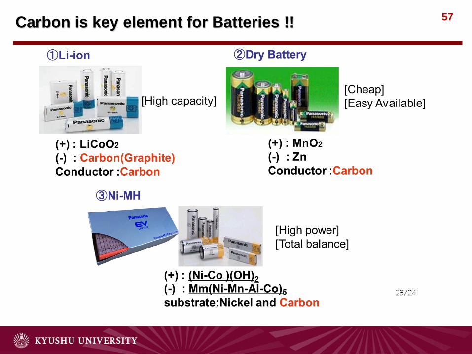
57 Carbon is key element for Batteries !!

58
リチウムイオン二次電池の動作原理

59 Electrode Materials for Lithium Secondary Battery
A spectacularly reactive cathode
Nature Materials 2, 705–706 (2003)
Different materials for different applications
+ Safety
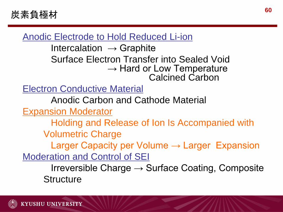
60 炭素負極材
Anodic Electrode to Hold Reduced Li-ion
Intercalation → Graphite
Surface Electron Transfer into Sealed Void → Hard or Low Temperature Calcined Carbon
Electron Conductive Material
Anodic Carbon and Cathode Material
Expansion Moderator
Holding and Release of Ion Is Accompanied with
Volumetric Charge
Larger Capacity per Volume → Larger Expansion
Moderation and Control of SEI
Irreversible Charge → Surface Coating, Composite
Structure

61
0.0
0.5
1.0
1.5
2.0
2.5
0 50 100 150 200 250 300 350Discharge capacity/Ah/kg
Pote
ntial/V
A B C D E F
炭素化温度と放電曲線の関係
A:2000C B:2200C C:2400C D:2600C
E:2800C F:3000C
黒鉛系材料

62
0.00
0.50
1.00
1.50
2.00
2.50
0 50 100 150 200 250 300
Discharge capacity/Ah/kg
Po
ten
tia
l/V
炭素化温度と放電曲線の関係
A:1800C B:1600C C:1400C D:1200C
A B C D
コークス系材料

63
0.0
0.5
1.0
1.5
2.0
2.5
0 200 400 600 800Discharge capacity/Ah/kg
Po
ten
tia
l/V
A B C D
炭素化温度と放電曲線の関係
A:1000C B:900C C:800C D:700C
低温焼成炭素系材料

64 バイオ由来のハードカーボン
IM is heat treated under Ar atmosphere with the heating rate of 10oC/min
0 100 200 300 400 500 600 700 800
0.0
0.5
1.0
1.5
2.0
0.0
0.5
1.0
1.5
2.0
IM950
IM1000
IM1050
IM700
IM800
IM900
(a)P
ote
ntia
l (V
, vs. L
i/L
i+)
Capacity (mAh/g)
(b)

65
65
Preparation and Analysis of SiO-CNF Composites
Electrochimica Acta, 55, 5519-5522 (2010)
65

66
66
Composite (Fe cat.) Mixture (CNF) Mixture (KB)
100
200
300
400
Vo
lum
e e
xp
an
sio
n (
%)
Electrolyte penetration only (2days)
After charging to 0V
301%
248%
153%
124% 126%112%
Comparison bet. Composite and Mixture

67 Cycle performances of PCSi-CNF composite
CARBON, 48, 3381-3391, 2009.

68
68
0 5 10 15 20 25 300
100
200
300
400
500
600
700
800
Dis
ch
ag
e c
ap
ac
ity
(mA
h/g
)
Cycle
20Si/PyC/CNF-30%
20Si/PyC/CNF-20%
20Si/PyC/CNF-10%
MAG
0 5 10 15 20 25 300
100
200
300
400
500
600
700
Dis
ch
ag
e c
ap
ac
ity
(mA
h/g
)
Cycle
50Si/PyC/CNF-30%
50Si/PyC/CNF-20%
50Si/PyC/CNF-10%
MAG
Si-CNF composite / Graphite Hybridization
69
Activated Carbons for Energy and
Environmental Devices

70
C C C
CO2
CO2 CO2 CO2
CO2 2CO
2CO 2CO
2CO
(Making small pores in the carbon materials)
C
C C C
Carbon materials
Activation reagents • Air, CO2, Steam • KOH (NaOH), ZnCl2
Activation(活性化)

71 71 活性炭の構造モデル

72
Water Filter Small Water filter
Felt Paper Manufacturing Products
• Thickness 1~8 mm
ACF Coat 60~100%
• Mixing organic fibers to
improve the strength and
dimension stability.
• Needle punched felt (FN
type) heat-processed felt
(FH type).
• Selection according to the concentration and amount
of the contaminant.
10
20
30
40
50
0 1 2 3
Water Amount (ton)
Ch
lori
ne R
esid
ue (
%)
Chlorine in Water:
2ppm
Water Flow Rate:
3l/min
Temperature: 20℃
• Thickness 0.2~0.8 mm
ACF Coat 60~70%
• Anti-water
• Anti-chemicals
• Easy formation into any
shapes
• Columnar
• Low resistivity
• Chlorine removal
ACF Products in Particular Forms

73 STM images of ACFs

74
VOCs
NVOCs: Dioxin, PCB
CO
Sick-house
gases
SO2
CO2
NO2
Ox
NO
SPM Toluene etc.
Benzene
Typical Hazard Gases in the Atmosphere

75
SO2 SO42-
ACF
2001
0
5
10
15
20
25
18:0
0
12:0
0
12:0
0
12:0
0
12:0
0
12:0
0
12:0
0
12:0
0
12:0
0
12:0
0
12:0
0
12:0
0
12:0
0
12:0
0
12:0
0
12:0
0
12:0
0
12:0
0
4/234/23 4/24 4/25 4/26 4/27 4/28 4/29 4/30 5/1 5/2 5/3 5/4 5/5 5/6 5/7 5/8 5/9
OG20A (0.100g)セット
ACF通過後の SO2濃度
環境SO2 濃度
SO
2濃度(ppb)
2001年 (17日間)
ACF (0.100g)
SO
2 (
pp
b) SO2
After ACF Ambient air
Lapse of time (day) Data from Dr. Shimohara
Of Fukuoka H & E Institute
活性炭素繊維を用いた道路辺のDeSOx

76
ACF surface
SO2(ad.) SO3(ad.) H2SO4(ad.)
SO2 O2 H2O H2O
aq. H2SO4
SO2
SO2+ad.→SO2ad.
SO2ad.+1/2O2→SO3ad.
SO3ad.+H2O→H2SO4ad.
H2SO4ad.+H2O→aq.H2SO4
×
DeSOx mechanism using ACF

77 DeSOx by ACF and CNF-ACF Composite
PDU for SOx Removal by ACF
DeSOx condition: SO2 1000ppm, O2 5vol%,
H2O 10vol%,
N2 balance、Total flow rate: 100 ml/min
Reaction Temperature: 50 ℃
Time (h)
PO-CNF 1%
cat., 5min
growing PO-CNF 5% cat.,
5min growing
H11000
DeSOx Properties of ACF and ACF-CNF

78 NO & NO2 Oxidation over ACF
ACF surface
NO(ad.) O(ad.) NO2(ad.) NO3(ad.)
NO O2 NO2 Heating
NO NO2
NO NO3
Identified reaction
aq.HNO3
Strong Inhibition of H2O
The oxidation of NO2 always produces NO
And NO3- through the disproportionation.

79 The Mechanism of NO Reductive Removal
ACF surface
NO(ad.) O(ad.) NO2(ad.) + NH3(ad.)
NO O2 NH3
N2 +H2O
The mechanism of NO removal consists of adsorption and
oxidation of NO into NO2 which is reduced with NH3

80 Characterization of ACF purification
ACF
Natural ventilation
Room temperature, ozonizer is no need, no light irradiation,
compact design
NO2
NO2
SPM
SO2
Hazardous
NH3
Odor
NO
NO
O3
Forced ventilation
chemicals
H2S
HCHO
ACF

Three-dimensional
wind vectors
Natural ventilation system (Fixed type)
ACF fence
Natural wind
81

82 Toluene adsorption characteristics of ACFs

83
0 1 2 3 4 5 6 7 8 9 10 11 120
10
20
30
40
50
60
C /
C0 / %
Time / h
HCHO adsorption characteristics of PACNF in humidified atmosphere
Experimental
HCHO : 11 ppm
Sample weight : 0.05g
Gas flow rate : 100ml / ml
Humidity of condition : 50%
PACNF
FE100
FE200
FE300
Under the circumstances of humidity (RH=50%),
PACNF shows specific prominent adsorption characteristics for formaldehyde.
0 1 2 3 4 5 6 7 8 9 10 11 120
10
20
30
40
50
60
C /
C0 / %
Time / h
PACNF
FE100
Experimental
HCHO : 11 ppm
Sample weight : 0.05g
Gas flow rate : 100ml / ml
Humidity of condition : 0%
RH BET Elemental analysis (wt%) Microporous
(m2 / g) C H N Odiff ash N / O ratio (%)
90% 375 68.06 1.19 18.02 11.41 1.32 1.80 94.7%
!!!

84 84
Carbons for Super Capacitor

85 Relationship Between Organic Capacitance And
Surface Area
1M Et4NBF4/PC, 2.7V, Capacitance per Volume
Present
Capacity

86
e-
e-
+
+ + +
+
+
+
+
+
+
+
e-
e- e- e-
e-
e-
e- e- +
+ +
-
+
+
+
+
+ + +
- -
- -
-
-
-
- - -
- -
Electrolyte:Et4NBF4
Porous carbon
Cation((C2H5)4N+) Anion(SO42-)
1.352nm
Ideal Model for capacitor
Stokes’ diameter : 0.676nm Stokes’ diameter : 0.517nm
M. Endo et al. , J. Electrochem.
Soc., 148 (8) A910-914 (2001).
In using Et4NBF4 as an electrolyte, at least pore size larger than 1.3nm is necessary to have electric
double layered capacitance.
Electrolyte:H2SO4
-
1.034nm
Conjecture of pore size using capacitance data
In using H2SO4 as an electrolyte, pore size of about 1.0nm is enough to have electric double layered
capacitance.
EDLC with organic electrolytes EDLC with inorganic electrolytes

87 Non-aqueous electrode
Specific capacitance
Surface property
Per weight
Per surface
area
Surface area
Average pore size
O contents
N contents
F/g mF/m2 m2/g nm % %
OG-5A 0.5 0.6 677 0.65 4.8 1.1
OG-7A 1.6 1.2 988 0.68 5.3 0.7
OG-10A 48.1 32.6 1212 0.77 6.1 0.5
OG-15A 72.5 41.7 1488 0.90 8.3 0.5
OG-20A 81.9 38.7 1817 1.08 6.7 0.3
Specific capacitance
Surface property
Per weight
Per surface
area
Surface area
Average pore size
O contents
N contents
F/g mF/m2 m2/g nm % %
FE-100 0.1 0.2 637 0.67 6.2 10.1
FE-200 0.1 0.2 909 0.72 7.4 6.1
FE-300 24.7 17.3 1131 0.78 7.9 4.1
FE-400 59.3 43.0 1187 0.82 9.3 2.5
0
20
40
60
80
100
120
140
160
180
0
20
40
60
80
100
120
140
160
180
OG-5A OG-7A OG-10A OG-15A OG-20A
Capacitance (F/g
)
Capacitance (m
F/m
2)
0
20
40
60
80
100
120
140
160
180
0
20
40
60
80
100
120
140
160
180
FE-100 FE-200 FE-300 FE-400
Capacitance (F/g
)
Capacitance (m
F/m
2)
Specific Capacitances in Non-Aqueous Electrolyte (Et4NBF4/PC)
Non-aqueous electrode
Specific capacitance
Surface property
Per weight
Per surface
area
Surface area
Average pore size
O contents
N contents
F/g mF/m2 m2/g nm % %
OG-5A 0.5 0.6 677 0.65 4.8 1.1
OG-7A 1.6 1.2 988 0.68 5.3 0.7
OG-10A 48.1 32.6 1212 0.77 6.1 0.5
OG-15A 72.5 41.7 1488 0.90 8.3 0.5
OG-20A 81.9 38.7 1817 1.08 6.7 0.3
Specific capacitance
Surface property
Per weight
Per surface
area
Surface area
Average pore size
O contents
N contents
F/g mF/m2 m2/g nm % %
FE-100 0.1 0.2 637 0.67 6.2 10.1
FE-200 0.1 0.2 909 0.72 7.4 6.1
FE-300 24.7 17.3 1131 0.78 7.9 4.1
FE-400 59.3 43.0 1187 0.82 9.3 2.5
0
20
40
60
80
100
120
140
160
180
0
20
40
60
80
100
120
140
160
180
OG-5A OG-7A OG-10A OG-15A OG-20A
Capacitance (F/g
)
Capacitance (m
F/m
2)
0
20
40
60
80
100
120
140
160
180
0
20
40
60
80
100
120
140
160
180
FE-100 FE-200 FE-300 FE-400
Capacitance (F/g
)
Capacitance (m
F/m
2)
Solvated electrolyte ions fail to enter into narrow
micropores.
OG series
FE series
Capacitance (m
F/m
2)
in Et4NBF4/PC
Cap
acitan
ce (F/g)
Capacitan
ce (m
F/m
2)
Cap
acitan
ce
(F/g)
OG 5A & FE 100
OG 15A & FE 300
Collector
+
+
+
+
+
+
+
+
+
++
+
++ +
+
Adsorbed BF4- ions
Free BF4- ions
OG 5A & FE 100
OG 15A & FE 300 Adsorbed BF4- ions
Free BF4- ions
OG-5A -7A -10A -15A -20A
FE-100 -200 -300 -400

88 Conclusion
Carbon is a key material for energy and environmental devices.
High Utilization of coal and petroleum residues as resources for advanced functional carbon is most necessary to develop the advanced energy and environmental devices.
Full understanding of carbon structure is necessary for improving the performance and useful applications of carbons
University:
Creation and leading of projects
Manpower cultivation

89
Thank you for your attentions!