(1921) gasoline automobiles
TRANSCRIPT

8/9/2019 (1921) Gasoline Automobiles
http://slidepdf.com/reader/full/1921-gasoline-automobiles 1/280
I

8/9/2019 (1921) Gasoline Automobiles
http://slidepdf.com/reader/full/1921-gasoline-automobiles 2/280
[LIBRARY
^UNIVERSITY OPCALIFORNIA
AN DIEGO i

8/9/2019 (1921) Gasoline Automobiles
http://slidepdf.com/reader/full/1921-gasoline-automobiles 3/280
^

8/9/2019 (1921) Gasoline Automobiles
http://slidepdf.com/reader/full/1921-gasoline-automobiles 4/280
8/9/2019 (1921) Gasoline Automobiles
http://slidepdf.com/reader/full/1921-gasoline-automobiles 5/280
GASOLINE AUTOMOBILES
8/9/2019 (1921) Gasoline Automobiles
http://slidepdf.com/reader/full/1921-gasoline-automobiles 6/280
\PODLJ_S_H_ER1 Of .BOOKS .F O R_/"
CoalAgel v tlectflcllailway Journal
Electrical World vEngineering News-Record
American Machinist, v Ingenieria Internacional
Engineering ^Mining Journal V Power
Chemical &Metallurgical Engineering
Electrical Merchandising
"
8/9/2019 (1921) Gasoline Automobiles
http://slidepdf.com/reader/full/1921-gasoline-automobiles 7/280
GASOLINE AUTOMOBILES
BY
JAMES A. MOYERDirector of University Extension, Massachusetts Department of Education;
formerly Junior Professor of Mechanical Engineering in the. University
of Michigan. Member of Society of Automotive Engineers,
and American Society of Mechanical Engineers;
formei ly member of Standards Committee of the
Society of Automobile Engineers.
FIRST EDITION
SECOND IMPRESSION
McGRAW-HILL BOOK COMPANY, INC.
NEW YORK: 370 SEVENTH AVENUE
LONDON: 6 & 8 BOUVERIE ST., E. C. 4

8/9/2019 (1921) Gasoline Automobiles
http://slidepdf.com/reader/full/1921-gasoline-automobiles 8/280
COPYRIGHT, 1921, BY THE
McGRAW-HILL BOOK COMPANY, INC.

8/9/2019 (1921) Gasoline Automobiles
http://slidepdf.com/reader/full/1921-gasoline-automobiles 9/280
PREFACE
THE purpose of this book is to present clearly, briefly,
and interestingly the essential principles of automobile con-
struction and operation. It is expected to furnish practical
help to drivers who, when faced by ordinary operating
troubles, want to know how to locate the cause and apply
the remedy.
Ordinarily an owner wishes to know first of all the uses
of the numerous parts of his automobile, so that he may
anticipate repairs and, when repairs actually become neces-
sary, he may know where to begin repair work, and whether,
once done, such work is right and the charges therefor are
reasonable.
Because of the increasing cost of materials and services
there is a growing tendency among owners to keep auto-
mobiles for several seasons. There is, therefore, more incen-
tive than formerly to keep automobiles in good repair. Auto-
mobiles generally deteriorate more because of lack of care
and attention than from actual use. Much of this deteriora-
tion is due to ignorance and the consequent failure to pre-
vent the kind of wear which, if not corrected, will lead to
heavy expenses for repairs.
As the cost of repairs has greatly increased of late be-
cause of labor charges, automobile operators are becoming
interested in finding ways of decreasing ordinary as well
as extraordinary running expenses. They want to learn
how to
getthe last unit of
powerfrom a
gallonof
gasolineand how to exact the greatest possible mileage from an auto-

8/9/2019 (1921) Gasoline Automobiles
http://slidepdf.com/reader/full/1921-gasoline-automobiles 10/280
vi PREFACE
A book prepared with these objects in view should also
be suitable for general scientific study, if, of course, the
theory is accurate and carefully explained. Such a book
will give information that will be most useful to students
of automotive engineering, whose schooling, obviously,
should not deal too much with minor details of automobile
equipment.
Many books on this subject are really catalogs of details,
and books, if at all complete, must be of unwieldy size and
include many dry and uninteresting data. The author be-
lieves that there is a demand for a readable book devoted
only to essentials. For example, not all types of carbureters
and ignition devices will be explained, but considerable
space will be devoted to the explanation of the principles
underlying commonly used equipment and systems. In the
description of carbureters a series of symbols has been
adopted which should make it easy to understand any type
mentioned after the careful study of one type. Only limited
space has been given to the subject of magnetos because
their use on automobiles, except on trucks, is rapidly de-
creasing in favor of simple battery systems of ignition.
The author is
especially
indebted to his brother J. C.
Moyer, consulting mechanical engineer, of Philadelphia, for
the preparation of portions of many chapters. Special
acknowledgment is also due to J. C. Vincent, Past-President
of Society of Automotive Engines and Vice-President of the
Packard Motor Car Company, to Charles W. Hobbs, Herbert
A. Dallas, agents of the Massachusetts Division of Univer-
sity Extension, and to Arthur E. Ashworth, Miss Betsy
McCausland, and Herbert S. Eames, instructors in the same
Division.
JAMES A. MOYER.
Boston, Mass.,
March, 1921.

8/9/2019 (1921) Gasoline Automobiles
http://slidepdf.com/reader/full/1921-gasoline-automobiles 11/280
CONTENTS
PREFACE v
CHAPTER PAQE
I AUTOMOBILE TYPES AND PARTS 1-20
II AUTOMOBILE ENGINES 21- 48
III GASOLINE AND SUBSTITUTES 49- 62
IV GASOLINE CARBURETERS 63-103
V AUTOMOBILE IGNITION 104-147
VI MAGNETOS AND IGNITION TESTING 148-166
VII ELECTRIC STARTERS 167-183
VIII CLUTCHES, TRANSMISSIONS AND DIFFERENTIALS 184-222
IX LUBRICATION AND COOLING SYSTEMS 223-246
X AUTOMOBILE TROUBLES AND NOISES 247-256
INDEX . 257

8/9/2019 (1921) Gasoline Automobiles
http://slidepdf.com/reader/full/1921-gasoline-automobiles 12/280

8/9/2019 (1921) Gasoline Automobiles
http://slidepdf.com/reader/full/1921-gasoline-automobiles 13/280
GASOLINE AUTOMOBILES
CHAPTER I
AUTOMOBILE TYPES AND PARTS
THE purpose of this book is to give such information
about the construction and maintenance of automobiles that
inexpert owners can make the simpler adjustments and
repairs intelligently and economically. The average man
is becoming more and more dependent on automobiles.
Economic considerations make it necessary for him to main-
tain and care for his automobile as easily and with as little
expense as he used to keep his horse and carriage.
Automobiles have given rise to extraordinary develop-
ments in modern industry and vast changes in methods of
transportation and living. Statistics of the number of
registered automobiles give some idea of the extent andnature of their use. In 1900 there were less than 20,000
automobiles in the United States. In 1910 there were about
50,000. In 1921 there are over 10,000,000. At the present
rate of production about 2,000,000 automobiles are manu-
factured annually in the United States, a large part of these
being for export to foreign countries.
With this enormous growth, the problem of an adequate
supply of fuel for automobiles has become increasingly
difficult. At present gasoline is used more extensively than
any other substance, but at times during recent years the
demand has exceeded the supply. Heretofore a balance
between supply and demand has been partially brought
about by (1) decreasing the demand by designing the auto-
mobile that have to do with combustion so that heavier

8/9/2019 (1921) Gasoline Automobiles
http://slidepdf.com/reader/full/1921-gasoline-automobiles 14/280
2 GASOLINE AUTOMOBILES
and cheaper grades of gasoline may be used, (2) reducing the
weight of automobiles so that the engine has less load to carry,
and (3) increasing the supply by the use of new methods
of distillation and the development of new oil fields. The
present high price of gasoline together with the increased
cost of labor for automobile repairs, has spurred the owners
to cut down the cost by taking more intelligent interest in
economical operation and proper care of their automobiles,
with the object of
(1) Eliminating the inconvenience of poorly operatingmachines.
(2) Keducing the charges for repairs and replacement
of broken and worn parts.
If the efforts to decrease demand and increase supply
still refuse to yield an adequate supply at a corresponding
price reduction, other fuels doubtless will become important
rivals of gasoline. In fact, a further increase of less than
fifty per cent in the price of gasoline will make alcohol an
important competitive fuel.
Classification of Automobiles. The various kinds of auto-
mobiles may be classified according to (1) kind of motive
power; (2) kind of service. These may be tabulated as
follows :
1. Kind of Motive Power:
a. Steam Engine
b. Electric Motor
c. Gasoline or Alcohol Engine.
2. Kind of Service:
a. Pleasure automobiles.
b. Commercial automobiles (trucks).
The following chapters will be devoted to the consideration
mainly of pleasure automobiles that receive their power
from gasoline engines though in the next few paragraphs
the advantages and disadvantages of steam automobiles and
electric automobiles will be explained.
Steam Automobiles. A steam driven automobile has im-
of difference when with a
8/9/2019 (1921) Gasoline Automobiles
http://slidepdf.com/reader/full/1921-gasoline-automobiles 15/280
AUTOMOBILE TYPES AND PARTS 3
automobile, the chief one being that the modern steam
automobile has, besides an engine, a steam boiler completely
equipped with pumps, water and steam gages, safety valve,
condenser, etc. Thus it is a complicated apparatus, requir-
ing careful attention. The steam automobile as compared
with the gasoline and electric kinds has several disadvan-
tages, the most important among them being that it cannot
be made instantly available for service. Even with the
most modern types of quick-firing portable steam boilers
it takes several minutes to heat water sufficiently to generate
enough steam to start the engine. Other disadvantages are
(1) that large quantities of water are needed for making
steam so that a considerable weight of water must be carried;
(2) that if there is no provision for condensing the steam and
using the water over again in the boiler, the distance that
can be traveled between refillings is very limited; (3) that
the cloud of steam discharged from such an engine especially
in cold weather is annoying to the -drivers of other con-
veyances; (4) that both the open flame which furnishes
heat to the boiler and the high steam pressure which is
necessary are objectionable because of the danger of fire
and destructive explosions.
There are, however, advantages in steam-driven vehicles,
of which the most obvious is the simplicity of speed control.
Merely by adjusting an ordinary throttling valve the pres-
sure of the steam admitted to the engine can be closely
regulated and thereby also the speed of the automobile.
The shifting of gears is never necessary on hilly roads or
in starting or reversing since a simple movement of links
controlling the steam valves gives all necessary control of
speed, power, and forward and backward movement.
Electric Automobiles. For simplicity and easy control
electric automobiles approach the ideal. By merely movinga small lever-switch, all the operations of changing speed,
reversing and maximum power are positively controlled. Anelectric automobile involves, however, the inconveniences

8/9/2019 (1921) Gasoline Automobiles
http://slidepdf.com/reader/full/1921-gasoline-automobiles 16/280
4 GASOLINE AUTOMOBILES
lead in order to furnish the power necessary for a high
speed and travelling in hilly country, and of having the bat-
tery recharged at a properly equipped place, every hundredmiles or less.
Gasoline Automobiles. Gasoline automobiles are the real
subject of these chapters, and all the following pages will
be devoted to the detailed descriptions of their parts. In
construction and methods of operation, when compared with
the steam and electric kinds, gasoline automobiles have the
disadvantage of having a type of engine which cannot be
started without special and expensive auxiliary equipment.
Furthermore, this type of engine in order to avoid "stalling"
if overloaded at normal engine speed, requires a system of
speed-change gearing between the engine and the wheels
on the driving axle.
Various mechanical and electrical devices however have
been applied to the modern gasoline automobile, so that in
spite of the disadvantages named, it has practically a non-
competitive field for general touring, pleasure, and business
services. The great advantage in its favor is that it can
carry a sufficient supply of gasoline for fuel, oil for lubrica-
tion and water for cooling the engine, to run from twohundred to four hundred miles without refilling. As the
result of very careful and thoughtful designing, it can be
run day after day with little attention, and, if carefully and
intelligently operated, with only small charges for repairs
and replacement of parts.
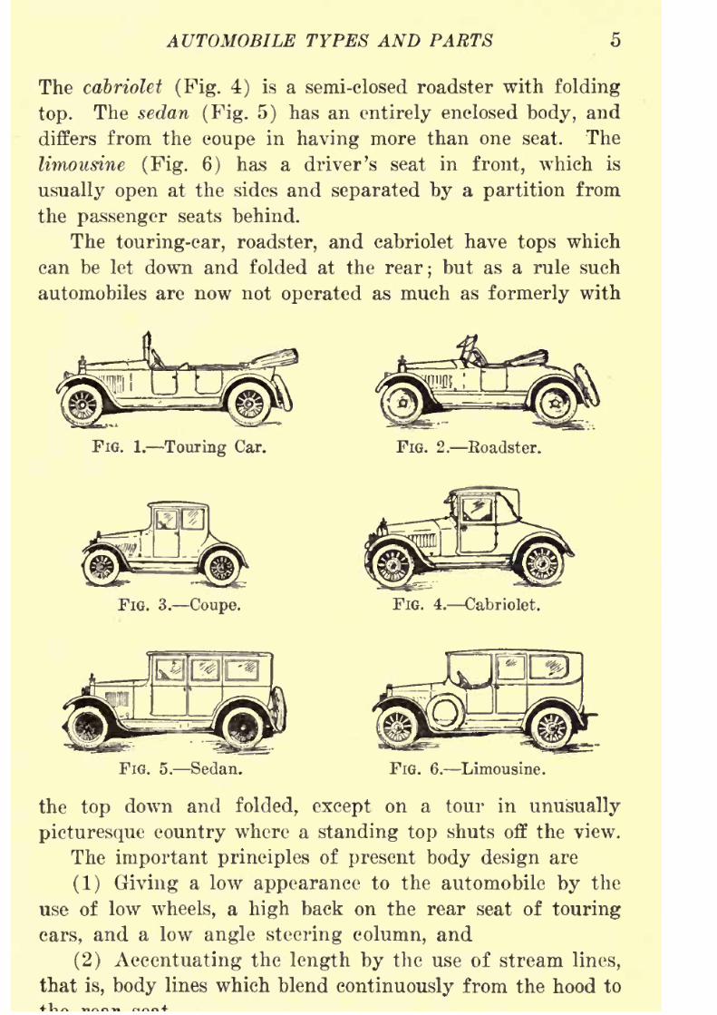
Types of Automobile Bodies. Automobiles are given
various names according to the style or type of the body,
which is generally taken to mean all that part above the
wheels to the rear of the sheet metal hood over the engine.
The touring-car body (Fig. 1) is the one most generally used
on pleasure cars. It has always front and rear seats and some-
times additional folding seats, and is made with a folding
top. The roadster (Fig. 2) resembles a touring car in general
lines but has only one seat. The coupe (Fig. 3) has only
8/9/2019 (1921) Gasoline Automobiles
http://slidepdf.com/reader/full/1921-gasoline-automobiles 17/280
AUTOMOBILE TYPES AND PARTS
The cabriolet (Fig. 4) is a semi-closed roadster with folding
top. The sedan (Fig. 5) has an entirely enclosed body, and
differs from the coupe in having more than one seat. The
limousine (Fig. 6) has a driver's seat in front, which is
usually open at the sides and separated by a partition from
the passenger seats behind.
The touring-car, roadster, and cabriolet have tops which
can be let down and folded at the rear; but as a rule such
automobiles are now not operated as much as formerly with
FIG. 1. Touring Car. FIG. 2. Roadster.
FIG. 3. Coupe. FIG. 4. Cabriolet.
FIG. 5. Sedan. FIG. 6. Limousine.
the top down and folded, except on a tour in unusually
picturesque country where a standing top shuts off the view.
The important principles of present body design are
(1) Giving a low appearance to the automobile by the
use of low wheels, a high back on the rear seat of touring
cars, and a low angle steering column, and
(2) Accentuating the length by the use of stream lines,
that is, body lines which blend continuously from the hood to
8/9/2019 (1921) Gasoline Automobiles
http://slidepdf.com/reader/full/1921-gasoline-automobiles 18/280
6 GASOLINE AUTOMOBILES
Eecent automobile designers favor a low-hung body, most
of the latest models having the floor of the body from three
to five inches nearer the ground than in the automobiles
made several years ago. The automobile with the low body
and low top has a pleasing appearance, but it is not so
easy riding as the high-hung body type, and is not so con-
veniently arranged for getting in and out.
The latest body designs are intended to give soft,
straight-line effects without necessarily sacrificing the beau-
tiful results obtained by the use of moderately rounded
corners. With too many curves there seems to be no char-
acter to the body, while with too many straight lines there
is harshness. A suitable combination of the two is required
to make a pleasing design. The present tendency is for
the roofs of enclosed bodies to be straight and nearly flat
with straight lines for the doors, because distinctly roundedcorners at the window openings and at the doors give the
impression of greater weight than straight-line corners, and
lightness in appearance is an important matter in present
body designs.
The weight of the body is a principal factor in determin-
ing the necessary strength in the automobile frame and
the engine power, and since an automobile for everyday
use does not usually require room enough for seven, and
since a shortage of the gasoline supply is quite possible,
designers of automobiles are now giving more and more
attention to the requirement of lightness.
Many hoods on automobiles have more louvres as the
vertical slots in the side of the hood are called than are
necessary. There are cases where the ventilating fan fo.r
cooling the engine draws nearly as much air through the
front louvres as it discharges through the rear ones. For
proper and efficient operation, the cooling air should enter
only from the front of the automobile and only the dis-
charged heated air pass through the louvres of the hood.Air circulation through the hood can be easily tested by

8/9/2019 (1921) Gasoline Automobiles
http://slidepdf.com/reader/full/1921-gasoline-automobiles 19/280
AUTOMOBILE TYPES AND PARTS 7
front louvres and observing whether the draft is outward,
as it should be.
For winter service, demountable tops for making enclosed
bodies on touring cars and roadsters are being sold with
the object of making them all-year automobiles, but because
of the difficulty of making the tops with pleasing body lines
and neat fittings, there is not much demand for them; the
coupe, sedan, and limousine still being the favorites for all-
year service.
The sedan has been coming into more general use of
late and has to a certain extent replaced the limousine.
It gained favor during the war when chauffeurs went into
army and navy service in large numbers, and driving had
to be done by the owner or by a member of his family. The
sedan made it possible for all members of the family to
sit
together,
without one of their numberbeing
shut off
by a glass partition, as would be the case in a limousine,
and gave protection to the driver in stormy weather. The
driver of a sedan, it is true, is at a disadvantage as compared
with the driver of a limousine, because he cannot hear or
see so readily as when sitting in the open; but except for
this disadvantage, the sedan is almost ideal as an all-year
transportation automobile. It gives satisfactory ventilation
and a fairly unobstructed view for the passengers in prac-
tically all conditions of winter and summer service even
when touring, and certainly for winter service it is at least
far more satisfactory and comfortable than the touring car
with its top up and its dilapitated side curtains.
A coupe with a roomy body is well adapted for summerand winter touring because suit-cases, traveling bags, and
boxes may be left in it with safety in a public garage since
the windows and doors of the car can be locked.
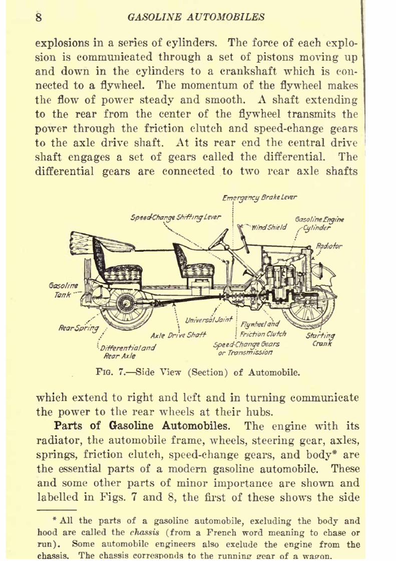
Flow of Power. Before explaining the details of auto-
mobile construction and operation it will be helpful to trace
the flow of
powerfrom its source in the
engineto the rear
wheels which drive the car.
8/9/2019 (1921) Gasoline Automobiles
http://slidepdf.com/reader/full/1921-gasoline-automobiles 20/280
8 GASOLINE AUTOMOBILES
explosions in a series of cylinders. The force of each explo-
sion is communicated through a set of pistons moving up
and down in the cylinders to a crankshaft which is con-
nected to a flywheel. The momentum of the flywheel makesthe flow of power steady and smooth. A shaft extending
to the rear from the center of the flywheel transmits the
power through the friction clutch and speed-change gears
to the axle drive shaft. At its rear end the central drive
shaft engages a set of gears called the differential. The
differential
gearsare connected to two rear axle shafts
EmergencyBrake Lever
Speeckhange ShiftingU
'V
GasolineEngintWfndShield /Cylinder
RearSpriny ,
\ UniversalJoint \
Axle Dri've Shaft
'
Differentialand
Rear Axle
I flynhettahd
\ Friction Ctufch
Speed^hancjedears
or Transmission
StartingCrank
FIG. 7. Side View (Section) of Automobile.
which extend to right and left and in turning communicate
the power to the rear wheels at their hubs.
Parts of Gasoline Automobiles. The engine with its
radiator, the automobile frame, wheels, steering gear, axles,
springs, friction clutch, speed-change gears, and body* are
the essential parts of a modern gasoline automobile. These
and some other parts of minor importance are shown and
labelled in Figs. 7 and 8, the first of these shows the side
*All the parts of a gasoline automobile, excluding the body and
hood are called the chassis (from a French wordmeaning
to chase or
run). Some automobile engineers also exclude the engine from the
chassis. The chassis to the of

8/9/2019 (1921) Gasoline Automobiles
http://slidepdf.com/reader/full/1921-gasoline-automobiles 21/280
AUTOMOBILE TYPES AND PARTS 9
view of an automobile with a touring car body as if cut
through the middle, and the second shows the same auto-
mobile (without body and hood) as seen when looking down
from the top. These figures give a good idea of the position
and relation of the essential parts.
The radiator shown at the front of the automobile in
Fig. 7 is really an essential part of the engine (sometimes
called the motor), which, by burning or "exploding" gasoline
in its enclosed cylinders, like C in the figure, turns the crank-
shaft or drive shaft. This shaft is connected at the front
end of the automobile to the starting crank for use when an
engine is started by hand, and at the other end is connected
to the friction clutch, which has a central shaft entering the
FIG. 8. Top View of Automobile Chassis.
speed-change gear box. Strong, interlocking, or meshing,
gear wheels in this gear box are on short shafts which can
be connected up in several ways through a universal joint
to the axle drive shaft connected to another set of gears
(called the differential) in the enlarged middle portion of
the rear axle. The gears in the rear axle are rigidly attached
on each side to enclosed rods which, when rotated, drive the
rear wheels. Power from the engine is thus transmitted to
the rear wheels, which by their gripping on the ground move
the automobile forward or backward as desired. The engine,
friction clutch, andspeed-change gear
box are
supportedon
the automobile frame, which is itself supported flexibly on
8/9/2019 (1921) Gasoline Automobiles
http://slidepdf.com/reader/full/1921-gasoline-automobiles 22/280
10 GASOLINE AUTOMOBILES
Brakes (Fig. 8) for stopping the automobile usually have
inside and outside bands with a mechanism to tighten them
against
a drum on each rear wheel in order to
providethe
necessary friction. Steel rods and links connect these bands
to the brake pedal and to the emergency brake lever in front
of the driver's seat.
The muffler is in nearly all automobiles a drum or cylinder
into which the exhaust pipe carries the exhaust gases. It
is used to stifle the noise of rapid explosions, which would
otherwise be deafening.
The purpose of the tires is to absorb road shocks and
make riding easy, as well as to keep the automobile from jolt-
ing to pieces.
Differential Gears. A means must be provided in auto-
mobiles to make it possible to drive the rear wheels so that
one wheel can turn faster than the other in going arounda corner. The rear axle is made, therefore, in two separate
pieces or separate axles, and each piece is connected at the
middle of the rear axle to differential gears. This gearing
device permits the two rear wheels to turn at different speeds
as necessary in driving along a curved road or in making a
sharpturn. If differential
gearswere not
providedand the
two rear wheels had to move at the same speed, when going
around a curve the wheel on the inside would have to slip
on the road bed without much turning motion. It would be
possible to get around a curve with an automobile with such
a single-piece axle, if it were not going fast, but one can
easily see that an automobile made with a one-piece axle
would be difficult to steer on a rough road and would soon
wear out its rear tires and wheel rims. When the rear end
of an automobile is jacked up and both hind wheels are off the
ground if the engine is started the wheels may be seen to turn
at different rates of speed. One wheel may not even turn
at all. This behavior is perfectly normal and is due to the
nature of the differential.
When an automobile is started with one rear wheel on

8/9/2019 (1921) Gasoline Automobiles
http://slidepdf.com/reader/full/1921-gasoline-automobiles 23/280
AUTOMOBILE TYPES AND PARTS 11
on slippery ground will often spin while the other does not
move at all. This is only another illustration of the peculiar
working of the differential gears and divided axle shaft.
The special tendency of automobile wheels to spin, slip,
and skid is offset to a considerable extent by the use of chains
and other friction devices which give the wheels a fairly
firm grip on slippery ground. A common type of rear axle,
divided in the middle and turned by the differential gears
is shown in Fig. 9. The figure shows that, though the rear
axle carries the power for moving the wheels it does not haveto bear the weight of the body. This burden is borne by
the heavy casing or housing, usually made of steel, in which
the axle shafts and differential gearing are enclosed. At A
Differential Gears
AxleCasing
or Housing
FIG. 9. Example of Bear Axle.
and B in the figure there are plates or lugs on the housing.
To these are attached the rear springs on which the body
frame is supported. When properly made and put together
the rear axle housing is sufficiently tight to keep out road
dust and to keep in the heavy oils which are used for the
purpose of lubricating the moving parts and deadening their
noise. Sometimes a rear axle which has been taken apartand reassembled, sputters oil over the wheels, brakes, or
other parts. When this is the case, the parts have not
been put together tightly. Ordinarily differential gears
cause very little trouble if their housing is kept well filled
with oil of good lubricating value and of proper thickness
to prevent leakage.
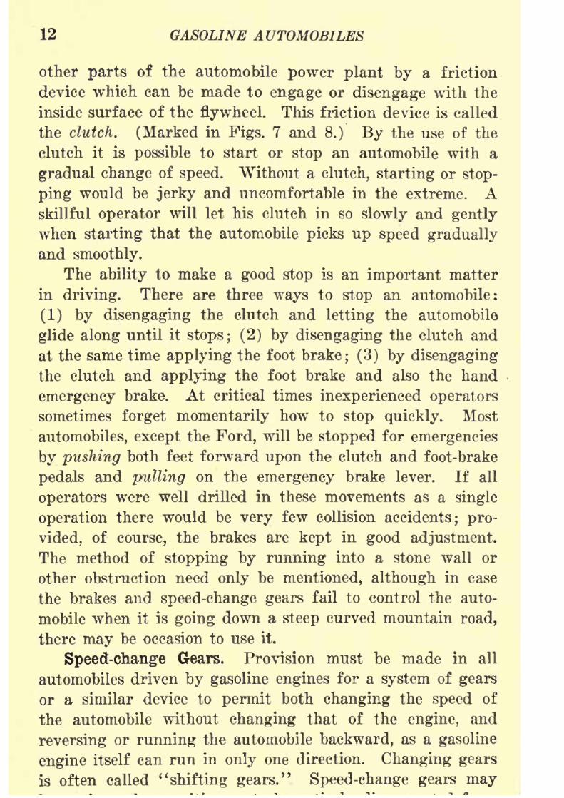
Friction Clutch. The power from the engine is trans-
8/9/2019 (1921) Gasoline Automobiles
http://slidepdf.com/reader/full/1921-gasoline-automobiles 24/280
12 GASOLINE AUTOMOBILES
other parts of the automobile power plant by a friction
device which can be made to engage or disengage with the
inside surface of the flywheel. This friction device is called
the clutch. (Marked in Figs. 7 and 8.) By the use of the
clutch it is possible to start or stop an automobile with a
gradual change of speed. Without a clutch, starting or stop-
ping would be jerky and uncomfortable in the extreme. Askillful operator will let his clutch in so slowly and gently
when starting that the automobile picks up speed gradually
and smoothly.
The ability to make a good stop is an important matter
in driving. There are three ways to stop an automobile:
(1) by disengaging the clutch and letting the automobile
glide along until it stops; (2) by disengaging the clutch and
at the same time applying the foot brake; (3) by disengaging
the clutch and applying the foot brake and also the handemergency brake. At critical times inexperienced operators
sometimes forget momentarily how to stop quickly. Most
automobiles, except the Ford, will be stopped for emergencies
by pushing both feet forward upon the clutch and foot-brake
pedals and pulling on the emergency brake lever. If all
operators were well drilled in these movements as a single
operation there would be very few collision accidents; pro-
vided, of course, the brakes are kept in good adjustment.
The method of stopping by running into a stone wall or
other obstruction need only be mentioned, although in case
the brakes and speed-change gears fail to control the auto-
mobile when it is going down a steep curved mountain road,
there may be occasion to use it.
Speed-change Gears. Provision must be made in all
automobiles driven by gasoline engines for a system of gears
or a similar device to permit both changing the speed of
the automobile without changing that of the engine, and
reversing or running the automobile backward, as a gasoline
engine itself can run in only one direction. Changing gearsis often called "shifting gears." Speed-change gears may

8/9/2019 (1921) Gasoline Automobiles
http://slidepdf.com/reader/full/1921-gasoline-automobiles 25/280
AUTOMOBILE TYPES AND PARTS 13
the axle drive shaft. They are then said to be "in neutral."
The gears should always be in neutral when the engine is
being started, or when "idling"; that is, running while the
automobile stands still.
The reasons for "shifting" gears are (1) to get more
pulling force on hilly and rough roads; (2) to get very low
automobile speed without reducing the engine speed so as
to risk its stopping by getting "stalled"; (3) to "reverse"
or to run the automobile backward. Speed-change gears are
also called the transmission.
The differential gears, the friction clutch, and the speed-
change gears have been referred to here in only a general
way so as to give an idea of the operation of the various
essential parts of an automobile. In later chapters these
parts will be described with detailed explanations and illus-
trations.Universal Joints. A little study of Fig. 7 will show that
the engine, clutch, and speed-change gears are rigidly mounted
on the frame and form a unit with it, while the rear axle
and rear wheels form another unit which rests upon the
ground and supports the frame by means of the springs. The
axle drive shaft, which connects these two units, must be
free to move somewhat in any direction, to be adjustable
when the car swerves slightly or when the rear axle moves
up and down as the wheels pass over rough places in the
road. The axle drive shaft is therefore provided with a joint
which allows flexible rotary motion between the speed-change
gears and the rear axle. This kind of joint is called a
universal joint. Fig. 10 shows a typical universal joint for
an axle drive shaft.
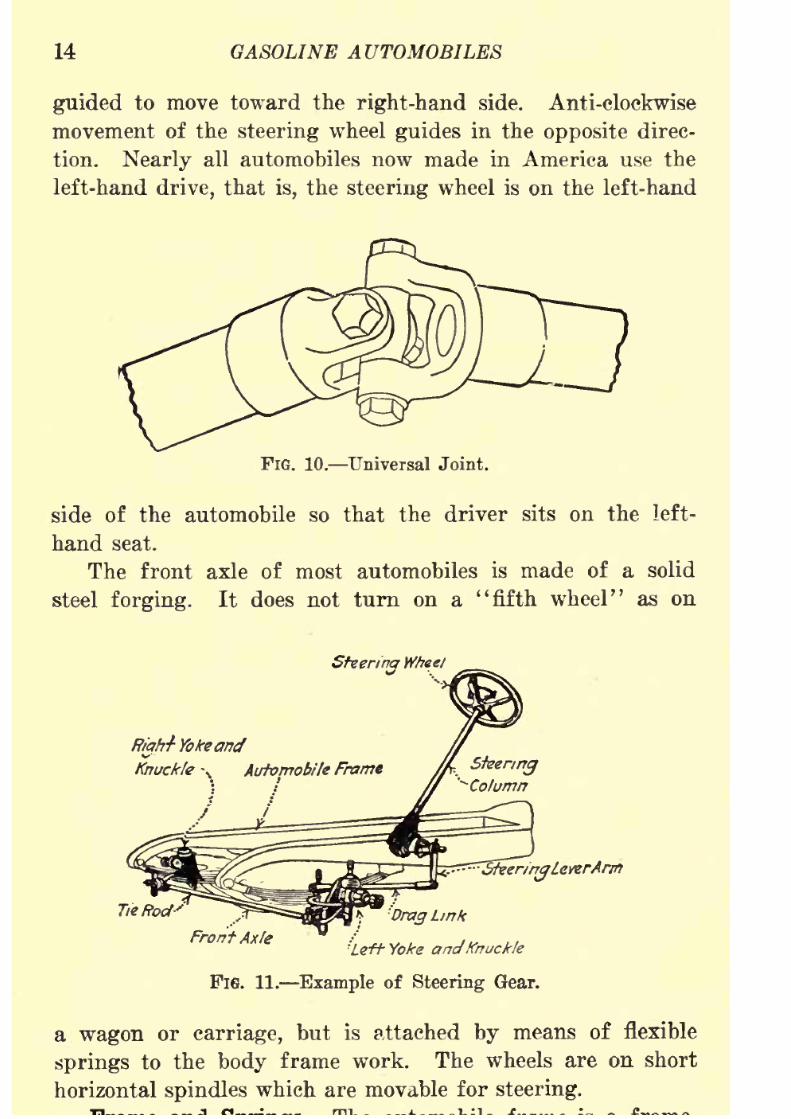
Steering Gears. The steering wheel which is used in
guiding the automobile is connected as shown in Fig. 11
by rods, levers, and gears (all called the steering gear) to
the ends of the front axle near each of the front wheels.
Turning the steering wheel in clockwise direction draws inthe right-hand front wheel toward the body and swings out-
8/9/2019 (1921) Gasoline Automobiles
http://slidepdf.com/reader/full/1921-gasoline-automobiles 26/280
14 GASOLINE AUTOMOBILES
guided to move toward the right-hand side. Anti-clockwise
movement of the steering wheel guides in the opposite direc-
tion. Nearly all automobiles now made in America use the
left-hand drive, that is, the steering wheel is on the left-hand
FIG. 10. Universal Joint.
side of the automobile so that the driver sits on the left-
hand seat.
The front axle of most automobiles is made of a solid
steel forging. It does not turn on a "fifth wheel" as on
Steering Wheel
ffiah-f- Yokeand
Knuckle-,.
Automobile Frame
'
SfaerirrgLeverAnn
*7 L,nk
Front Axle /^ y gndKnuekle
Fie. 11. Example of Steering Gear.
a wagon or carriage, but is attached by means of flexible
springsto the
bodyframe work. The wheels are on short
horizontal spindles which are movable for steering.

8/9/2019 (1921) Gasoline Automobiles
http://slidepdf.com/reader/full/1921-gasoline-automobiles 27/280
AUTOMOBILE TYPES AND PARTS 15
work made usually of steel but sometimes of wood, to support
the engine, radiator, friction clutch, speed-change gear box,
engine drive shaft, and all other parts not attached directly
to the axles. It is claimed that a wooden frame transmits
less vibration and is easier riding than a steel frame, but
actually there is little difference between frames of steel and
of wood when they are equally well designed. The frame is
supported on springs as shown in the figures. A long frame
FIG. 12. Spring Leaves.
makes possible a long wheel base, which is the distance
measured between the centers of the front and rear axles.
This is considered desirable since an automobile with a long
wheel base usually rides more comfortably than one with a
short wheel base.
Automobile springs are made in exactly the same way that
springs have been made for a hundred years for use in horse-
drawn carriages. The usual kind of springs used for attach-
FIG. 13. Spring Leaves Assembled.
ing the automobile frame to the axles is made oT~a number
of flat steel plates called leaves (Fig. 12), which are tapered
at the ends and bent into curved shapes as shown in Fig. 13,
each leaf being given a little greater curvature than the next
longer one. The leaves for a complete spring are pressed
together and fastened with clamps. In addition to the clamp-
ing, the leaves are sometimes put together more permanently
with a bolt passing through the middle of each leaf (Fig. 14).
Although all automobile body springs are made by the

8/9/2019 (1921) Gasoline Automobiles
http://slidepdf.com/reader/full/1921-gasoline-automobiles 28/280
16 GASOLINE AUTOMOBILES
same general method, there are several types or arrangements
in use.
Full Elliptic Springs. A spring made by fastening to-
gether with hinged ends two sets of leaves as shown in Fig. 15
is called a full elliptic spring. It gives very easy riding
and in this respect is most satisfactory, but it is not generally
FIG. 14. Bolted Automobile Spring. FlG. 15. Full Elliptic Spring.
used for automobiles because it takes up too much room to
be adaptable to low-hung automobile bodies. It is attached
to an automobile by fastening the middle of the top part to
the automobile frame and the middle of the lower part to
the axle.
FIG. 16. Three-quarters Elliptic Spring.
Three-quarters Elliptic Spring. Fig. 16 shows a kind of
automobile spring made with a set of leaves at the bottom
which are hinged to half of a similar set at the top. This
type is called a three-quarters elliptic spring. It is attached
to the automobile frame at the end of the short top part at
8/9/2019 (1921) Gasoline Automobiles
http://slidepdf.com/reader/full/1921-gasoline-automobiles 29/280
AUTOMOBILE TYPES AND PARTS 17
to a pin bolted to the side of the frame at B. The two ends
of the spring are joined by a pin at C. The axle is fastened
to the middle of the lower part.
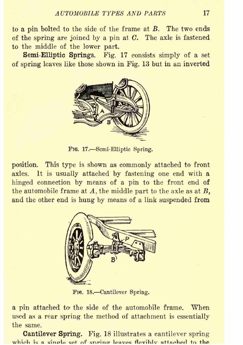
Semi-Elliptic Springs. Fig. 17 consists simply of a set
of spring leaves like those shown in Fig. 13 but in an inverted
FlG. 17. Semi-Elliptic Spring.
position. This type is shown as commonly attached to front
axles. It is usually attached by fastening one end with a
hinged connection by means of a pin to the front end of
the automobile frame at A, the middle part to the axle as at B,
and the other end is hung by means of a link suspended from
TIG. 18. Cantilever Spring.
a pin attached to- the side of the automobile frame. When
used as a rear spring the method of attachment is essentially
the same.
Cantilever Spring. Fig. 18 illustrates a cantilever spring

8/9/2019 (1921) Gasoline Automobiles
http://slidepdf.com/reader/full/1921-gasoline-automobiles 30/280
18 GASOLINE AUTOMOBILES
side of the automobile frame at one end and at the middle,
while the other end is rigidly fastened to the rear axle. As
shown in the figure the spring is clamped securely at the
FIG. 19. Platform Springs.
middle to a block B, which is itself supported and turns on
a pin P bolted to the side of the frame.
Platform Spring. Fig. 19 consists of two semi-elliptic
springs each attached at one end by links to the side of the
FlO. 20. Inverted Semi-Elliptic Spring
(Ford Type Front Spring).
frame, at the middle to the rear axle, and at the other ends
by means of links to a third spring, fastened at the middle
to an extension of the frame.
Inverted Semi-Elliptic Springs. Figs. 20 and 21 are used
FIG. 21. Inverted Semi-Elliptic Spring
(Ford Type Bear Spring).
on some light weight automobiles because of simplicity
and cheapness in construction. Only one spring is used
8/9/2019 (1921) Gasoline Automobiles
http://slidepdf.com/reader/full/1921-gasoline-automobiles 31/280
AUTOMOBILE TYPES AND PARTS 19
In each case the spring is attached at the middle to the
frame with its length parallel to the axle, and the two ends
are fastened by links to the axle near the wheels.
Lubrication of Springs. The first automobiles were built
without provision for reducing the friction of the springs.
Neither the bolts used nor the holes in the springs into which
they fitted were carefully made to give smooth working
surfaces, and there was continuous squeaking. The springs
of modern automobiles, however, are provided at all pin
connections or other flexible attachments with oil or grease
cups for lubrication. Some types of springs are made with
small depressions which are filled with a mixture of graphite
and lubricating grease, in order to eliminate friction between
the leaves. These provisions for lubrication together with
carefully made and low-friction linings or bushings for the
bolt holes have made squeaking at the spring joints easilyavoidable.
Automobile Engines. The engine of a gasoline auto-
mobile furnishes the driving power. It is usually made
with a number of cylinders in which occurs the burning or
exploding of a highly combustible mixture of gasoline vapor
and air, which furnishes the power. As a rule the larger
the number of cylinders the more even and steady the
propelling power will be. The "explosions" in a one-
cylinder engine for instance, are strong, few, and far be-
tween, making this kind of engine unusually noisy. Two-
cylinder engines are not much used on automobiles, and
three-cylinder engines practically never. Four-cylinder
engines are used more than any others, since with this
number of cylinders it is possible to make the individual
cylinders so small that none of the"explosions" will be
noisy and a sufficiently uniform turning movement is secured
on the driving shaft to give easy and steady running quali-
ties. In a four-cylinder engine there is a power impulse
every half revolution, in a six-cylinder engine every one-third revolution, in an eight-cylinder engine every one-
8/9/2019 (1921) Gasoline Automobiles
http://slidepdf.com/reader/full/1921-gasoline-automobiles 32/280
20 GASOLINE AUTOMOBILES
one-sixth revolution. The reasons for this are not explained
here but will be fully discussed in the next chapter. It
should be clear, however, from this statement that with
increased number of cylinders in an automobile engine there
is greater so-called"flexibility
"with smoother running,
easier starting, and less vibration. Eight-cylinder and
twelve-cylinder engines because of the uniformity of the
"flow of power" can be operated at very slow speed with-
out using speed-change gears, except for starting and for
exceptionally heavy pulling and are able to "pick up"speed much more rapidly than the automobile having a
four-cylinder engine.
8/9/2019 (1921) Gasoline Automobiles
http://slidepdf.com/reader/full/1921-gasoline-automobiles 33/280
CHAPTER II
AUTOMOBILE ENGINES
The detailed study of gasoline automobiles begins
naturally with the most important part, the engine, or the"motor" as it is commonly called in the automobile industry.
In the following pages, however, the name engine will be
used exclusively to avoid confusion in later chapters when
the name "motor" will be used in referring to the electric
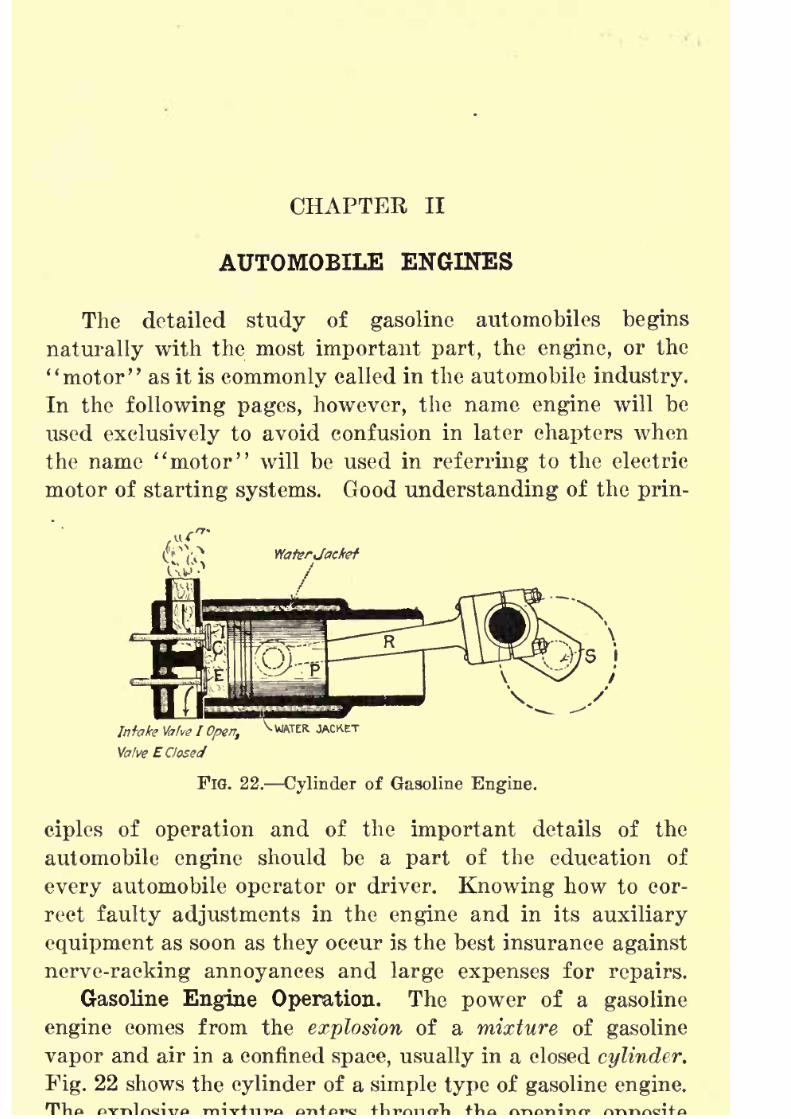
motor of starting systems. Good understanding of the prin-
Intafa Valve I Open,
Valve E Closed
^ WATER JACKET
FlG. 22. Cylinder of Gasoline Engine.
ciples of operation and of the important details of the
automobile engine should be a part of the education of
every automobile operator or driver. Knowing how to cor-rect faulty adjustments in the engine and in its auxiliary
equipment as soon as they occur is the best insurance against
nerve-racking annoyances and large expenses for repairs.
Gasoline Engine Operation. The power of a gasoline
engine comes from the explosion of a mixture of gasoline
vapor and air in a confined space, usually in a closed cylinder.
Fig. 22 shows the cylinder of a simple type of gasoline engine.

8/9/2019 (1921) Gasoline Automobiles
http://slidepdf.com/reader/full/1921-gasoline-automobiles 34/280
22 GASOLINE AUTOMOBILES
the valve disk I. If after taking in a quantity of explosive
mixture, this opening is closed and the mixture is exploded,
the movable plunger, or piston P of the engine will be forced
by the explosion toward the right-hand end of the cylinder,
just as a ball is driven from the free end of a cannon by the
explosion of the powder behind it (Fig. 23). An explosion
is really nothing more than the practically instantaneous
burning of a highly inflammable material. In a gasoline
engine the explosion results from the very rapid burning of
gasoline vapor mixed with air. Such a mixture when putinto an engine cylinder must have proper proportions. It
is possible to use so much gasoline that the mixture is too
"rich" to explode effectively. On the other hand, with too
FIG. 23. Explosive Force in a Cannon.
little gasoline in the mixture the explosion is too weak. Be-
tween the mixtures that are too "rich" and those that are
too weak, or "lean," there is a wide range of mixtures which
are highly explosive. The proper explosive mixture of gaso-
line vapor and air is of fundamental importance. In the
following chapters there will be frequent references to this
subject.
Fig. 24 represents diagrammatically a gasoline engine
divided through the center in cross-section, showing the
cylinder C with its plunger, or piston. On the left-hand
side is the intake pipe through which the explosive mixture
enters the cylinder. On the right-hand side is the exhaust
pdpe through which the burned mixture called exhaust gases
escapes from the cylinder. A most important device called
8/9/2019 (1921) Gasoline Automobiles
http://slidepdf.com/reader/full/1921-gasoline-automobiles 35/280
AUTOMOBILE ENGINES 23
device, when properly adjusted, mixes automatically the
right proportions of gasoline and air for the explosive mix-
ture. The parts of a carbureter are delicate and can be
adjusted so that the proportions of the mixture may be
changed to suit the varying conditions of engine operations
in summer and winter, in high and low altitudes.
When the force caused by the explosion of the mixture
in the engine cylinder drives the piston (Fig. 24) downward
this motion is transmitted through the connecting rod R
to give rotary motion to the crank shaft 8, which revolves
and on each explosion stroke receives enough force to move
the piston up and down during the return stroke as well
as also during the other strokes when no power is developed.
A heavy wheel on the crank shaft, called a flywheel, is used
as a means of storing up energy during the explosion stroke
to be used later in turning over the engine during the other
three strokes when there are no power impulses. From the
engine crank shaft the power is transmitted by means to be
fully described later, to the rear wheels, and the automobile
thus gets its driving power. The steel casing which surrounds
the crank shaft and lower part of the connecting rods is called
the crank case.
Engine Types. There are two principal kinds of gasoline
engines, named according to the number of up and down
movements, or strokes of the piston occurring between one
explosion or power stroke and the next power stroke. The
kind used almost exclusively for automobiles has one ex-
plosion in every four strokes of the piston. In this kind of
engine, the explosion stroke together with the other threestrokes (until the next explosion) are called its cycle; and
because there are four strokes in its cycle it is called a four-
stroke or four-cycle engine. Another kind of engine not
often used on automobiles but much used for marine purposes
has only one stroke between an explosion stroke and the
next. It has, therefore, only two strokes in a cycle and is
called a two-stroke or two-cycle engine. In every piston

8/9/2019 (1921) Gasoline Automobiles
http://slidepdf.com/reader/full/1921-gasoline-automobiles 36/280
24 GASOLINE AUTOMOBILES
half turn of the crank shaft. Briefly then a standard type
of automobile engine has four strokes or two complete revolu-
tions of the crank shaft in its cycle.
IntakePipe,Spark PIug-K
FIG. 24. Automobile Engine.
Intake Position.
FIG. 25. Automobile Engine.
Compression Position.
FIG. 26. Explosion
Position.
FIG. 27. Exhaust
Position.
Four-stroke Automobile Engine. Figs. 24, 25, 26, 27,
show the positions of the engine piston in the four strokes
in a four-stroke cycle; that is, from the beginning say of
an stroke till the is back in
8/9/2019 (1921) Gasoline Automobiles
http://slidepdf.com/reader/full/1921-gasoline-automobiles 37/280
AUTOMOBILE ENGINES 25
for the next explosion. For simplicity of explanation, the
description of what takes place during the four strokes of
such a cycle will begin with the intake or suction stroke, as
shown in Fig. 24 when the piston is moving downward in
the direction of the arrow to draw the mixture of gasoline
vapor and air from the intake pipe into the cylinder. During
this stroke the engine must suck in the explosive mixture
just as an air-pump sucks in air before compressing it, or as
the ordinary wooden pump draws water by suction from a
well. After the explosive mixture of gasoline vapor and air
is in the cylinder the intake valve I closes, making an air
tight chamber. After this the piston rises as shown in Fig.
25 and compresses the imprisoned mixture. This compression
of the explosive mixture is an important part of the cycle,
as it causes an explosion pressure from three to five times
greater than would be possible without compression. Com-
pression also serves to mix more evenly the gasoline vapor
with the air and at the same time raises the temperature so
that good ignition is made easier. Anyone who has operated
an automobile engine in both winter and summer knows how
much more easily good ignition is secured with warm air than
with cold air.
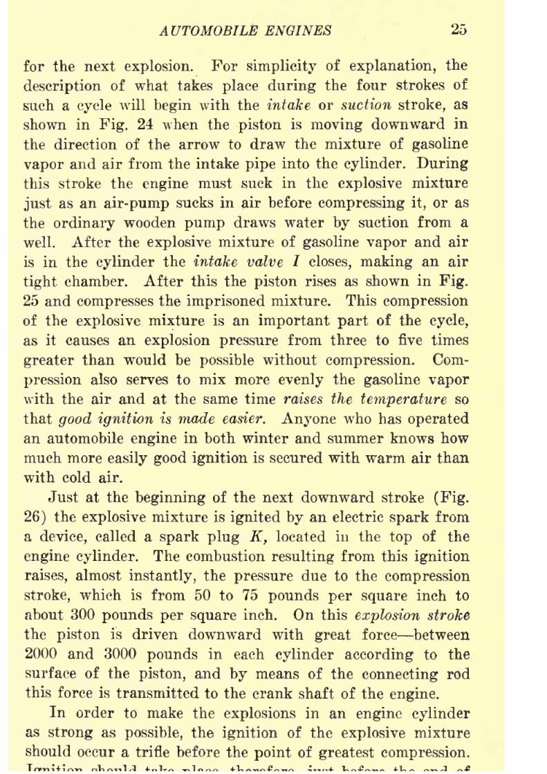
Just at the beginning of the next downward stroke (Fig.
26) the explosive mixture is ignited by an electric spark from
a device, called a spark plug K, located in the top of the
engine cylinder. The combustion resulting from this ignition
raises, almost instantly, the pressure due to the compression
stroke, which is from 50 to 75 pounds per square inch to
about 300 pounds per square inch. On this explosion strokethe piston is driven downward with great force between
2000 and 3000 pounds in each cylinder according to the
surface of the piston, and by means of the connecting rod
this force is transmitted to the crank shaft of the engine.
In order to make the explosions in an engine cylinder
as strong as possible, the ignition of the explosive mixture
should occur a trifle before the point of greatest compression.
8/9/2019 (1921) Gasoline Automobiles
http://slidepdf.com/reader/full/1921-gasoline-automobiles 38/280
26 GASOLINE AUTOMOBILES
the compression stroke. The faster the engine is running
the earlier in this stroke the ignition should occur. This is
what is meant when one says the "spark" or ignition should
be "advanced," that is, occur earlier at high than at low
speed.
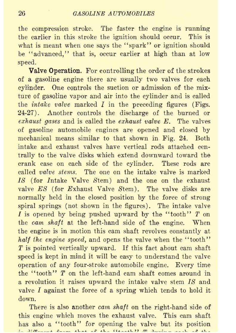
Valve Operation. For controlling the order of the strokes
of a gasoline engine there are usually two valves for each
cylinder. One controls the suction or admission of the mix-
ture of gasoline vapor and air into the cylinder and is called
the intake valve marked / in the preceding figures (Figs.
24-27). Another controls the discharge of the burned or
exhaust gases and is called the exhaust valve E. The valves
of gasoline automobile engines are opened and closed by
mechanical means similar to that shown in Fig. 24. Both
intake and exhaust valves have vertical rods attached cen-
trally
to the valve disks which extend downward toward the
crank case on each side of the cylinder. These rods are
called valve stems. The one on the intake valve is marked
IS (for intake Valve /Stem) and the one on the exhaust
valve E8 (for Exhaust Valve /Stem). The valve disks are
normally held in the closed position by the force of strong
spiral springs (not shown in the figures). The intake valve
/ is opened by being pushed upward by the "tooth" T on
the cam shaft at the left-hand side of the engine. When
the engine is in motion this cam shaft revolves constantly at
half the engine speed, and opens the valve when the "tooth"
T is pointed vertically upward. If this fact about cam shaft
speed is kept in mind it will be easy to understand the valve
operation of any four-stroke automobile engine. Every timethe "tooth" T on the left-hand cam shaft comes around in
a revolution it raises upward the intake valve stem IS and
valve / against the force of a spring which tends to hold it
down.
There is also another cam shaft on the right-hand side of
this
enginewhich moves the exhaust valve. This cam shaft
has also a "tooth" for opening the valve but its position

8/9/2019 (1921) Gasoline Automobiles
http://slidepdf.com/reader/full/1921-gasoline-automobiles 39/280
AUTOMOBILE ENGINES 27
engine strokes just described. The exhaust valve is kept
tightly closed during the intake stroke. During the com-
pression (Fig. 25) both valves remain closed during the whole
stroke so that the explosive mixture is
"trapped" within
the cylinder and none of it can escape. Both valves are
closed also during the explosion or power stroke.
When the piston is at the bottom of the explosion stroke
and is about to begin the next upward stroke, called the
exhaust stroke, the "tooth" on the right-hand cam shaft comes
into contact with the valve stem E8 andpushes open
the
exhaust valve E. On this stroke, as the piston goes up, the
space in the cylinder above the piston becomes continually
smaller, and with the exhaust valve open, the burned mixture
is driven out through the exhaust pipe into the atmosphere,
clearing the cylinder to receive the next fresh explosive
mixture.
Summary of Four-stroke Engine Operation. By drawing
down the engine piston during the suction stroke a vacuum
is created in the upper part of the cylinder. At the right
moment the intake valve is opened and a mixture of gasoline
vapor and air is sucked in. Then the intake valve closes and
the rising piston compresses this charge. When the piston
reaches its highest point an electric spark is introduced throughthe spark plug. The explosion stroke gives enough power to
carry the crank over the strokes which have no power
impulses.
There are four strokes, or up and down movements, of
the piston in each cycle of a four-stroke engine. The first
which draws in the mixture is called the suctionstroke;
the
next is the compression stroke, the third is the explosion or
power stroke, and the fourth is the exhaust stroke, when the
burned gases are expelled from the engine cylinder. During
these four strokes there are two complete revolutions of the
crank shaft. The explosion or power stroke does all the useful
work in turning the engine crank shaft, which moves the
automobile. The suction and the compression strokes serve
to in the mixture and it for
8/9/2019 (1921) Gasoline Automobiles
http://slidepdf.com/reader/full/1921-gasoline-automobiles 40/280
28 GASOLINE AUTOMOBILE^
efficient explosive burning. The exhaust stroke serves only
for cleaning out the cylinder.
Engine Flywheels. For every four strokes of a four-
stroke engine there are three "idle" strokes during which
no power is developed. During these "idle" strokes the
pistpn must be driven from the crank shaft, and in most
engines the power to keep the crank shaft moving during
these "idle" strokes must come from "stored energy" or
momentum in a flywheel. Flywheels as provided on auto-
mobileengines
areusually
apart
of thefriction
clutch.(See
Chapter 1, page 9.) A flywheel is made extra heavy because
it is difficult to stop a heavy wheel when revolving at high
speed. A flywheel of proper weight when once started will
keep an engine running for some time. A well designed
automobile engine of six or more cylinders once started will,
however, keep itself going without a flywheel if all its cylinders
are operating.
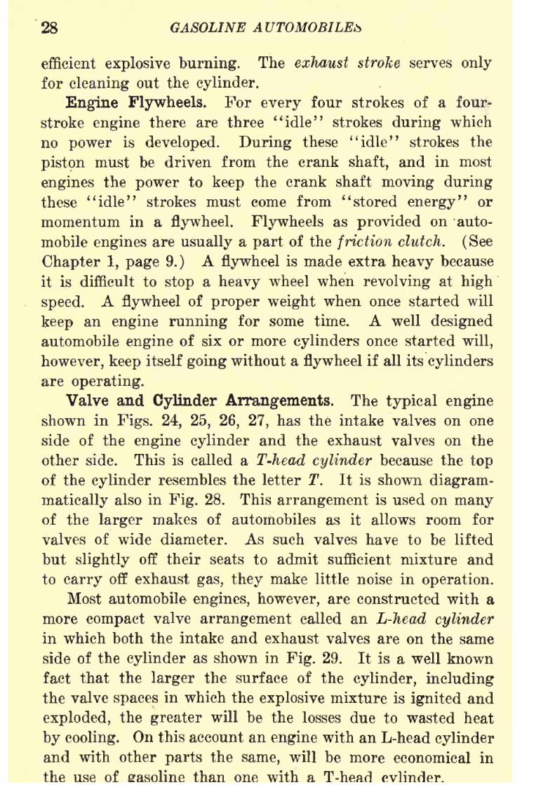
Valve and Cylinder Arrangements. The typical engine
shown in Figs. 24, 25, 26, 27, has the intake valves on one
side of the engine cylinder and the exhaust valves on the
other side. This is called a T-head cylinder because the top
of the cylinder resembles the letter T. It is shown diagram-
matically also in Fig. 28. This arrangement is used on manyof the larger makes of automobiles as it allows room for
valves of wide diameter. As such valves have to be lifted
but slightly off their seats to admit sufficient mixture and
to carry off exhaust gas, they make little noise in operation.
Most automobile engines, however, are constructed with a
morecompact
valve
arrangementcalled an L-Jiead
cylinderin which both the intake and exhaust valves are on the same
side of the cylinder as shown in Fig. 29. It is a well known
fact that the larger the surface of the cylinder, including
the valve spaces in which the explosive mixture is ignited and
exploded, the greater will be the losses due to wasted heat
by cooling. On this account an engine with an L-head cylinder
and with other parts the same, will be more economical in
the use of than with

8/9/2019 (1921) Gasoline Automobiles
http://slidepdf.com/reader/full/1921-gasoline-automobiles 41/280
AUTOMOBILE ENGINES 29
Fig. 30 shows a valve and cylinder arrangement called
valve-in-the-head. The valves are in the center of the top
of the engine cylinder and open downward. This affords
a very short passage for the explosive mixture into the cylinder,
and a very small surface around the valves exposed to cooling.
This is sometimes called an I-head cylinder. "Valves-in-the-
head" have, therefore, special advantages as regards power
and economy, but they are likely to be more noisy than other
types.
Though most automobile engines are at present made with
the L-head construction, there is an increasing number being
built with the ''valve-in-the-head" arrangement.
FIG. 28. T-Head
Engine Cylinder.
FIG. 29. L-Head
Engine Cylinder.
FIG. 30. Valve-in-the-
Head EngineCylinder.
Slide Valve Engines. The elimination of noise in auto-
mobile engines has always been an important consideration.
It is well known that a great deal of the noise in engine
operation is due to the valves. In any engine in which the
ordinary so-called poppet valves are used there is necessarilysome noise from the valves, especially after repairing, if the
lengths of the push rods are not carefully adjusted. On the
other hand, slide valves are almost noiseless and their use
on all kinds of engines is not new. In fact, the first gas
engines ever built were made with slide valves;but on account
of the high temperature in such engines there was excessive
wear and warping and it was difficult to keep the exhaust
8/9/2019 (1921) Gasoline Automobiles
http://slidepdf.com/reader/full/1921-gasoline-automobiles 42/280
30 GASOLINE AUTOMOBILES
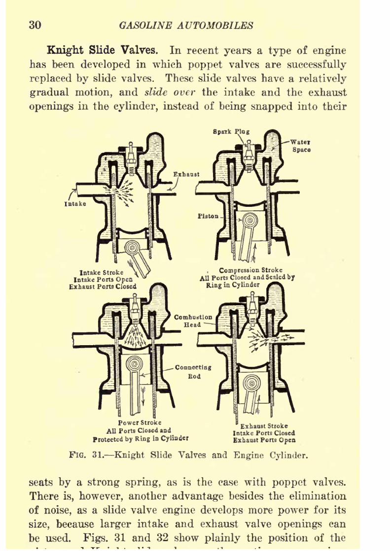
Knight Slide Valves. In recent years a type of engine
has been developed in which poppet valves are successfully
replaced by slide valves. These slide valves have a relatively
gradual motion, and slide over the intake and the exhaust
openings in the cylinder, instead of being snapped into their
Intake Stroke
Intake Ports OpenExhaust Ports Closed
Compression Stroke
All Ports Closed and Sealed by
Ring La Cylinder
Power Stroke
All Ports Closed and
Protected by Ring in Cylinder
Exhaust Stroke
Intake Ports Closed
Exhaust Ports Open
FIG. 31. Knight Slide Valves and Engine Cylinder.
seats by a strong spring, as is the case with poppet valves.
There is, however, another advantage besides the elimination
of noise, as a slide valve engine develops more power for its
size, because larger intake and exhaust valve openings canbe used. Figs. 31 and 32 show plainly the position of the
8/9/2019 (1921) Gasoline Automobiles
http://slidepdf.com/reader/full/1921-gasoline-automobiles 43/280
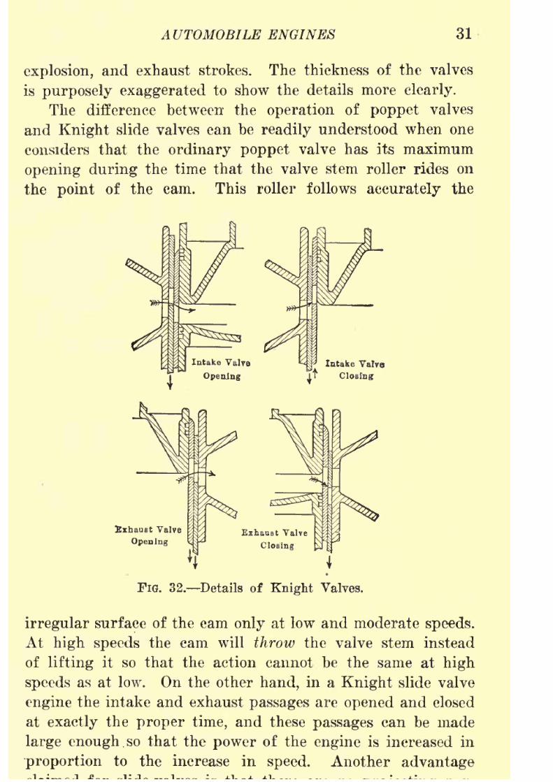
AUTOMOBILE ENGINES 31
explosion, and exhaust strokes. The thickness of the valves
is purposely exaggerated to show the details more clearly.
The difference between the operation of poppet valves
and Knight slide valves can be readily understood when one
considers that the ordinary poppet valve has its maximum
opening during the time that the valve stem roller rides on
the point of the cam. This roller follows accurately the
Exhaust Valve
Opening
FIG. 32. Details of Knight Valves.
irregular surface of the cam only at low and moderate speeds.
At high speeds the cam will throw the valve stem instead
of lifting it so that the action cannot be the same at high
speeds as at low. On the other hand, in a Knight slide valve
engine the intake and exhaust passages are opened and closed
at exactly the proper time, and these passages can be made
large enoughso that the
powerof the
engineis increased in
proportion to the increase in speed. Another advantage

8/9/2019 (1921) Gasoline Automobiles
http://slidepdf.com/reader/full/1921-gasoline-automobiles 44/280
32 GASOLINE AUTOMOBILES
tides of metal or of carbon on the valves to remain hot after
the discharge of the exhaust gases to cause premature explo-
sions of the incoming fresh mixture.
Pistons and Piston Rings. Formerly all gasoline engine
pistons were made of gray cast iron. Recently a number
of manufacturers of automobile engines have been using
pistons made of aluminum alloys. Aluminum pistons are
much lighter than those made of cast iron and therefore
reduce the weight to be supported by the engine crank shaft.
Reducing the weight on the crank shaft reduces also the
vibration of the shaft and makes an engine quieter in
operation. Aluminum is a better conductor of heat than iron.
The use of this metal makes it easier to keep the pistons cool.
Engine pistons are never made to fit tightly in the
cylinders. The pistons must be made a trifle smaller than the
inside of the cylinders to make provision for:1. A film of oil between the curved part of the piston
and the walls of the cylinder.
2. The greater expansion of the piston than of tha
cylinder, because of the greater heating of the
piston.
Aluminum expands more than cast iron, therefore aluminum
pistons must be made to fit more loosely in the cylinders than
those of cast iron.
It is not economical to allow the explosive mixture to
escape between the pistons and the cylinder walls into the
crank case during the compression stroke. To prevent such
leakage, the pistons are fitted with elastic cast-iron rings,
called piston rings, placed in grooves around the body of
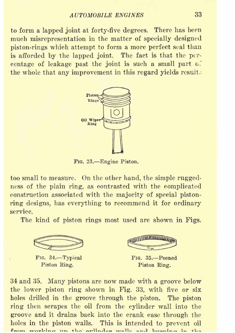
each piston. As a rule, three rings are placed in each piston
as shown in Fig. 33.
The most satisfactory piston rings are of the concentric
type in which the thickness is uniform all around the ring.
The varying degree of elasticity which is required in the
ringin order that it should tend to
expandin a circle
and fill the cylinder bore is attained by certain peening
8/9/2019 (1921) Gasoline Automobiles
http://slidepdf.com/reader/full/1921-gasoline-automobiles 45/280
AUTOMOBILE ENGINES 33
to form a lapped joint at forty-five degrees. There has been
much misrepresentation in the matter of specially designed
piston-rings which attempt to form a more perfect seal than
is afforded by the lapped joint. The fact is that the per-
centage of leakage past the joint is such a small part or
the whole that any improvement in this regard yields result.,
FlG. 33. Engine Piston.
too small to measure. On the other hand, the simple rugged-
ness of the plain ring, as contrasted with the complicated
construction associated with the majority of special piston-
ring designs, has everything to recommend it for ordinary
service.
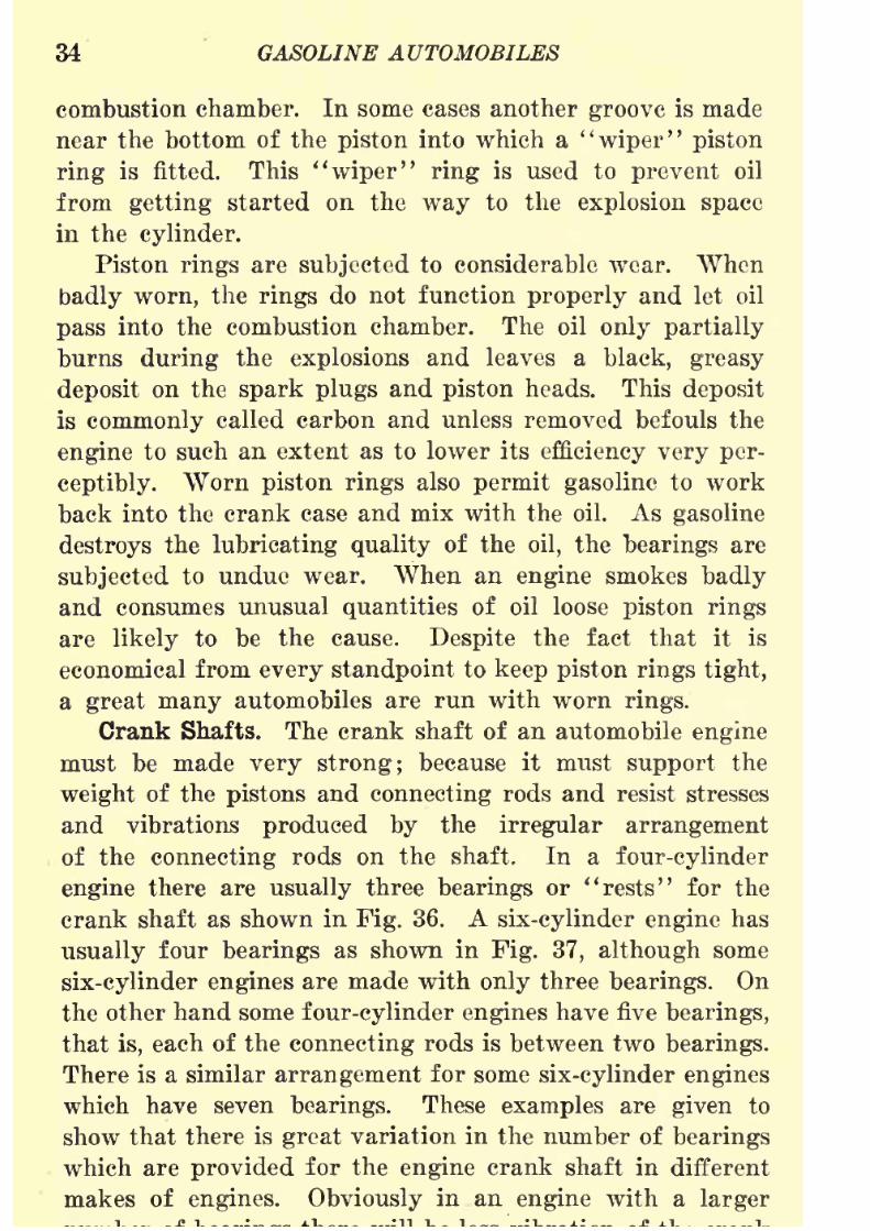
The kind of piston rings most used are shown in Figs.
FIG. 34. Typical FIG. 35. Peened
Piston King. Piston Eing.
34 and 35. Many pistons are now made with a groove below
the lower piston ring shown in Fig. 33, with five or six
holes drilled in the groove through the piston. The piston
ring then scrapes the oil from the cylinder wall into the
groove and it drains back into the crank case through the
holes in the piston walls. This is intended to prevent oil
8/9/2019 (1921) Gasoline Automobiles
http://slidepdf.com/reader/full/1921-gasoline-automobiles 46/280
34 GASOLINE AUTOMOBILES
combustion chamber. In some cases another groove is made
near the bottom of the piston into which a"wiper" piston
ring is fitted. This "wiper" ring is used to prevent oil
from getting started on the way to the explosion space
in the cylinder.
Piston rings are subjected to considerable wear. When
badly worn, the rings do not function properly and let oil
pass into the combustion chamber. The oil only partially
burns during the explosions and leaves a black, greasy
deposit on the spark plugs and piston heads. This deposit
is commonly called carbon and unless removed befouls the
engine to such an extent as to lower its efficiency very per-
ceptibly. Worn piston rings also permit gasoline to work
back into the crank case and mix with the oil. As gasoline
destroys the lubricating quality of the oil, the bearings are
subjectedto undue wear. When an
enginesmokes
badlyand consumes unusual quantities of oil loose piston rings
are likely to be the cause. Despite the fact that it is
economical from every standpoint to keep piston rings tight,
a great many automobiles are run with worn rings.
Crank Shafts. The crank shaft of an automobile engine
must be made very strong; because it must support the
weight of the pistons and connecting rods and resist stresses
and vibrations produced by the irregular arrangement
of the connecting rods on the shaft. In a four-cylinder
engine there are usually three bearings or "rests" for the
crank shaft as shown in Fig. 36. A six-cylinder engine has
usually four bearings as shown in Fig. 37, although some
six-cylinder engines are made with only three bearings. Onthe other hand some four-cylinder engines have five bearings,
that is, each of the connecting rods is between two bearings.
There is a similar arrangement for some six-cylinder engines
which have seven bearings. These examples are given to
show that there is great variation in the number of bearings
which areprovided
for theengine
crank shaft in different
makes of engines. Obviously in an engine with a larger

8/9/2019 (1921) Gasoline Automobiles
http://slidepdf.com/reader/full/1921-gasoline-automobiles 47/280
AUTOMOBILE ENGINES 35
shaft than in an engine with fewer bearings. On the other
hand, a larger number of bearings add materially to the
expenseof
making an engine.Fig. 36, illustrating the crank shaft of a four-cylinder
Ftywheet
FIG. 36. Crank Shaft for Four-Cylinder Engine.
engine with three bearings, shows the conventional arrange-
ment of pistons corresponding to the firing order, No. 1,
No. 2, No. 4, No. 3. These numbers are consecutive on the
engine for the cylinders numbered from the front of the
ConnectingRod 'PistonRing ..--CrankShaftBearing
Flywheel / \ ^Piston / ..- Connecting RodBearing
,.,-CrarT(Shaft
'.. CranffShaff'
6ear
....
Starting
Nut
FIG. 37. Crank Shaft for Six-Cylinder Engine.
automobile. The pistons in the two middle cylinders move
up and down together and the pistons in the two end
cylinders similarly move together. This means that when

8/9/2019 (1921) Gasoline Automobiles
http://slidepdf.com/reader/full/1921-gasoline-automobiles 48/280
36 GASOLINE AUTOMOBILES
the exhaust stroke and Xos. 2 and 3 are respectively on the
suction and explosion strokes.
Engine Speeds.
The maximum speed of a four-cylinder
engine is about eighteen hundred revolutions of the crank
shaft per minute. The highest speed of six-cylinder engines
is from two thousand to twenty-five hundred revolutions
per minute, and eight- and twelve-cylinder engines are
usually designed for a maximum speed of three thousand
to thirty-five hundred revolutions per minute.
Arrangement of Cylinders in Automobile Engines. Early
automobile engines were made with one or two horizontal
cylinders. With the introduction of engines with four ver-
tical cylinders came an era of great improvement in auto-
mobile construction. This kind of engine is compact,
accessible, and can be built in units giving reasonably high
horsepower ; also, the distribution of explosive mixture froma single carbureter presents no difficulties. The useful power
range of a four-cylinder automobile engine may be con-
sidered to lie between four hundred and eighteen hundred
revolutions per minute, which corresponds to an automobile
speed of from twelve to sixty miles per hour. For the low
speed requirements of congested automobile traffic the
speed-change gears of a four-cylinder engine must be shifted
frequently.
The next improvement in automobile engines was to
increase the number of cylinders from four to six, or eight.
These engines with more frequent power strokes met in-
stantly the demand for more power, more flexibility, more
smoothness, and less noisy operation. A six-cylinder auto-
mobile engine will doubtless be a standard type for many
years as it has many advantages over a four-cylinder engine,
and avoids much of the complication and excessive upkeep
expense of eight-cylinder and twelve-cylinder engines.
There are, however, certain structural difficulties which limit
the general application of such engines in cheaply constructedautomobiles. The crank shaft of a six-cylinder engine is

8/9/2019 (1921) Gasoline Automobiles
http://slidepdf.com/reader/full/1921-gasoline-automobiles 49/280
AUTOMOBILE ENGINES 37
permit making it as stout as might be desired. Because of
this slenderness there is a certain amount of twisting which
causes considerable vibration of the crank shaft in every
revolution. At some speeds (called "critical") these vibraT
tions become excessive and disagreeable to passengers. They
are, of course, more noticeable in a large engine of high power
with a slender crank shaft than in small ones.
The next step in the development of automobile engines
was the introduction of eight- and twelve-cylinder engines.
Four-cylinder engines and six-cylinder engines are alwaysmade with the cylinders in a row. Eight-cylinder engines
and twelve-cylinder engines as usually made should be con-
sidered as two four-cylinder engines or two six-cylinder
engines built up with the same crank shaft and crank case
for the attachment of two rows of cylinders. It is easy
to see that to some extent atleast,
aneight-cylinder engine
must have the disadvantages of a four-cylinder engine, and
that a twelve-cylinder engine will correspondingly have the
disadvantages of a six-cylinder engine.
For the same horsepower, the individual cylinders of
an eight-cylinder engine are considerably smaller than those
of a four-cylinder engine of the same horsepower, and,
because the moving parts of individual cylinders are lighter
in weight there is less vibration than in a four-cylinder
engine. The objection to some six-cylinder engines because of
vibration of a slender crank shaft applies, of course, equally
to a twelve-cylinder engine, except that the method of con-
struction with two rows of small cylinders permits the use
of a crank shaft actually shorter than would be installed
in a six-cylinder engine.
The best authorities agree that there is little likelihood
that practical automobile engines will be built with more
than twelve cylinders.
Compared with the simplicity of construction of the
standardfour-cylinder
andsix-cylinder engines
there are
many practical difficulties in the construction of an auto-

8/9/2019 (1921) Gasoline Automobiles
http://slidepdf.com/reader/full/1921-gasoline-automobiles 50/280
38 GASOLINE AUTOMOBILES
a six-cylinder engine has the disadvantage of having a
relatively long crank shaft. This difficulty is obviously
much increased with eight cylinders in a row. There is
also the further disadvantage that with eight cylinders in
a row the hood of the automobile is excessively long. Eight-
cylinder engines are, therefore, made as a rule in two
rows of four cylinders each, with the cylinders placed in most
makes so that each row is at an angle of forty-five degrees from
the vertical center line of the engine ;in other words, the
two rows of cylinders are made with an angle of ninety
degrees between them.
The advantages of eight cylinders over four other than
the increased power are as follows :
(1) more even turning power; (2) greater flexibility;
(3) less vibration. Practically continuous power is obtained
in aneight-cylinder engine
because one of its
cylindersgives a power stroke every quarter revolution of the engine
crank shaft and each one of these power impulses lasts
about three-quarters of the stroke, which is the same as saying
that the power impulse is effective for each of the cylinders
for three-eighths of a revolution. It is obvious, therefore,
that the power strokes aided by the momentum of the fly-
wheel, will overlap and give almost perfectly constant power.
This explanation should make it clear that an eight-cylinder
engine with its four power strokes per revolution should
give more uniform power than a six-cylinder engine with
three explosions per revolution, and that it will be twice as
smoothly running as a four-cylinder engine with only two
explosions per revolution. Fig. 38 shows the relative con-
tinuity or "flow" of power in engines having one, two, four,
six, and eight cylinders.
From the foregoing, it is easy to understand that there
is the same increase in smooth running and of steady power
application in a twelve-cylinder engine when compared with
asix-cylinder
or aneight-cylinder engine.
It wasjust
explained that with an eight-cylinder engine there were

8/9/2019 (1921) Gasoline Automobiles
http://slidepdf.com/reader/full/1921-gasoline-automobiles 51/280
AUTOMOBILE ENGINES 39
twelve-cylinder engine there are six explosions per revolu-
tion and the overlapping of power strokes is still more
pronounced.
Typical Automobile Engines. One-, two-, and three-
cylinder automobile engines are now so infrequently used
that no space need be given to their description. In essen-
tial parts they are not very different from the modern types
of automobile engines with more cylinders. Fig. 39 shows
Legend
Excess Energy abore
Useful Energy
negative Work
Six Cylinder Engine
jfisft
.JLAAAJ
Eight Cylinder Engine
FIG. 38. Relative Flow of Power.
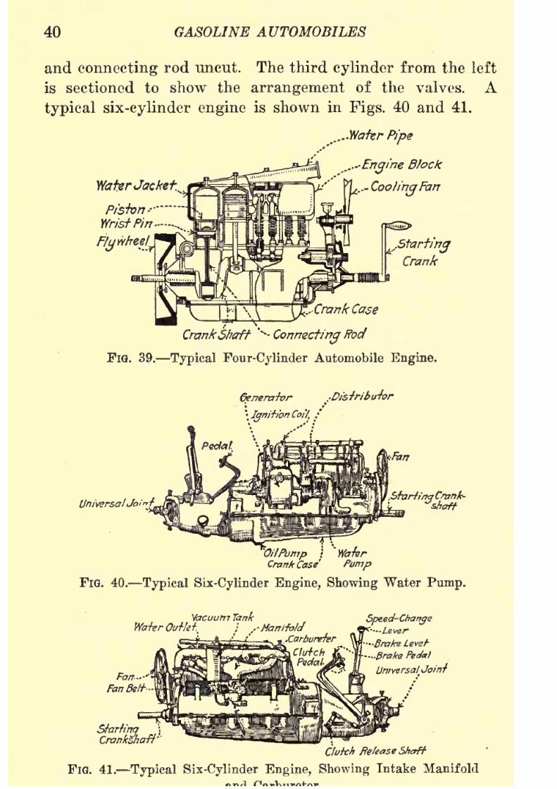
a typical four-cylinder engine and may be considered repre-
sentative of standard usage. The four cylinders are arrangedwith their connecting rods attached to the same crank shaft
operating in a single enclosed crank case. A section of
the crank case and two of the cylinders are shown broken
away to make clear the attachment of the connecting rods
to the crank shaft. The first cylinder from the left is cut
in two through the middle to show the construction of the
piston, connecting rod and wrist pin. The next cylinder
8/9/2019 (1921) Gasoline Automobiles
http://slidepdf.com/reader/full/1921-gasoline-automobiles 52/280
40 GASOLINE AUTOMOBILES
and connecting rod uncut. The third cylinder from the left
is sectioned to show the arrangement of the valves. A
typical six-cylinder engine is shown in Figs. 40 and 41.
WaterJacket.
....Water Pipe
....-EngineBlock
-CooIing
Fan
..StartingCrank
.-Crank Case
CrankShaftv-
ConnectingRod
FlG. 39. Typical Four-Cylinder Automobile Engine.
Generator
\Ignit/bn Coif, .'
.ShrttrtqCrank-
OilPump \
Crank Case Pump
FIG. 40. Typical Six-Cylinder Engine, Showing Water Pump.
Vacuum Tank
Water Outte^ ; ..-Manifold.Carbureter
Clutch Release Shaft-
FIG. 41. Typical Six-Cylinder Engine, Showing Intake Manifold
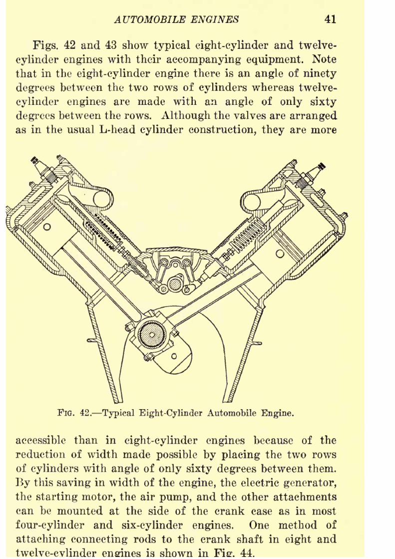
8/9/2019 (1921) Gasoline Automobiles
http://slidepdf.com/reader/full/1921-gasoline-automobiles 53/280
AUTOMOBILE ENGINES 41
Figs. 42 and 43 show typical eight-cylinder and twelve-
cylinder engines with their accompanying equipment. Note
that in the eight-cylinder engine there is an angle of ninety
degrees between the two rows of cylinders whereas twelve-
cylinder engines are made with an angle of only sixty
degrees between the rows. Although the valves are arranged
as in the usual L-head cylinder construction, they are more
FlG. 42. Typical Eight-Cylinder Automobile Engine.
accessible than in
eight-cylinder enginesbecause of the
reduction of width made possible by placing the two rows
of cylinders with angle of only sixty degrees between them.
By this saving in width of the engine, the electric generator,
the starting motor, the air pump, and the other attachments
can be mounted at the side of the crank case as in most
four-cylinder and six-cylinder engines. One method of
attaching connecting rods to the crank shaft in eight and
is shown in
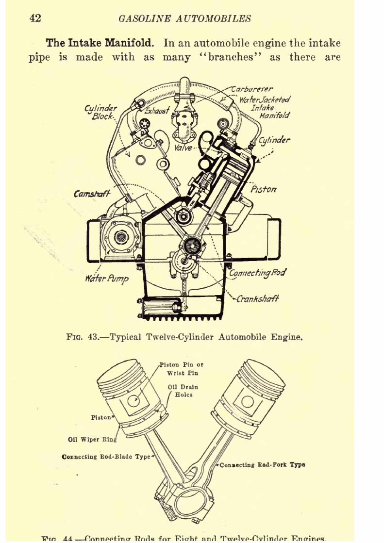
8/9/2019 (1921) Gasoline Automobiles
http://slidepdf.com/reader/full/1921-gasoline-automobiles 54/280
42 GASOLINE AUTOMOBILES
The Intake Manifold. In an automobile engine the intake
pipe is made with as many "branches" as there are
Cylindery
'arburerer
WaterJacketed
Intake
Manifold
Cylinder
Camshaft
ConnectingRod
^-Crankshaft
FIG. 43. Typical Twelve-Cylinder Automobile Engine.
Oil Wiper King
Connecting Bod-Blade Type
meeting Bod- Fork Type

8/9/2019 (1921) Gasoline Automobiles
http://slidepdf.com/reader/full/1921-gasoline-automobiles 55/280
AUTOMOBILE ENGINES 43
cylinders. These "branches" of the intake pipe are called
the intake manifold. In some recent engines the "branches"
of the manifold going to the intake valves are cast in the
sides of the cylinders. The advantage of this construction
is that the manifold can be kept warm by the heat of the
engine and the carbureter can be placed high and close to
the cylinders.
Power Plant Suspension. In nearly all recently designed
FlG. 45. Four-point
Suspension.
FIG. 46. Three-point
Suspension.
automobile engines the clutch and speed-change gears are
combined with the engine in practically a continuous casing
in such a way as to form what we call a single power plant
unit. This "unit construction" has the advantage of retain-
ing positively the alignment of the shafts in the speed-change
gears, under most conditions of operation. This method of
setting up the engine, clutch, and speed-change gears makesit also easy to apply what is called the three-point suspension.

8/9/2019 (1921) Gasoline Automobiles
http://slidepdf.com/reader/full/1921-gasoline-automobiles 56/280
44 GASOLINE AUTOMOBILES
In some automobiles the engine and speed-change gear case
are attached to the automobile frame at four points two in
the front and two near the middle of the frame as in Fig. 45.
This method has the disadvantage that in case of distortion
of the frame caused by operation over very rough roads, or
by a collision, it is difficult to adjust the alignment of the
engine crank shaft, the clutch and the shafts of the speed-
change gears, so that there would not be excessive wear on
the several parts. Because of these difficulties the three-point
suspensionwas introduced. This method of
suspensionmeans
that the power plant unit is supported as in Fig. 46 on two
Rear SupportsonSide Brackets
Front Power Plant
Support
FIG. 47. Three-point Suspension Applied to Dodge Engine.
points in front and one point near the speed-change gears.
In the Dodge automobile (Fig. 47) the three-point suspen-
sion is reversed. There is one point of suspension in front
and two other supports on brackets at the rear end of the
crank case. It should be evident that with the three-point
suspension there can be considerable distortion of the frame
without interfereing with the correct alignment of any parts
of the unit power plant.
Engine Cylinders. Most four-cylinder and six-cylinder
engines are made with all the cylinders in a single casting.
This is called block cylinder construction. It makes the engine
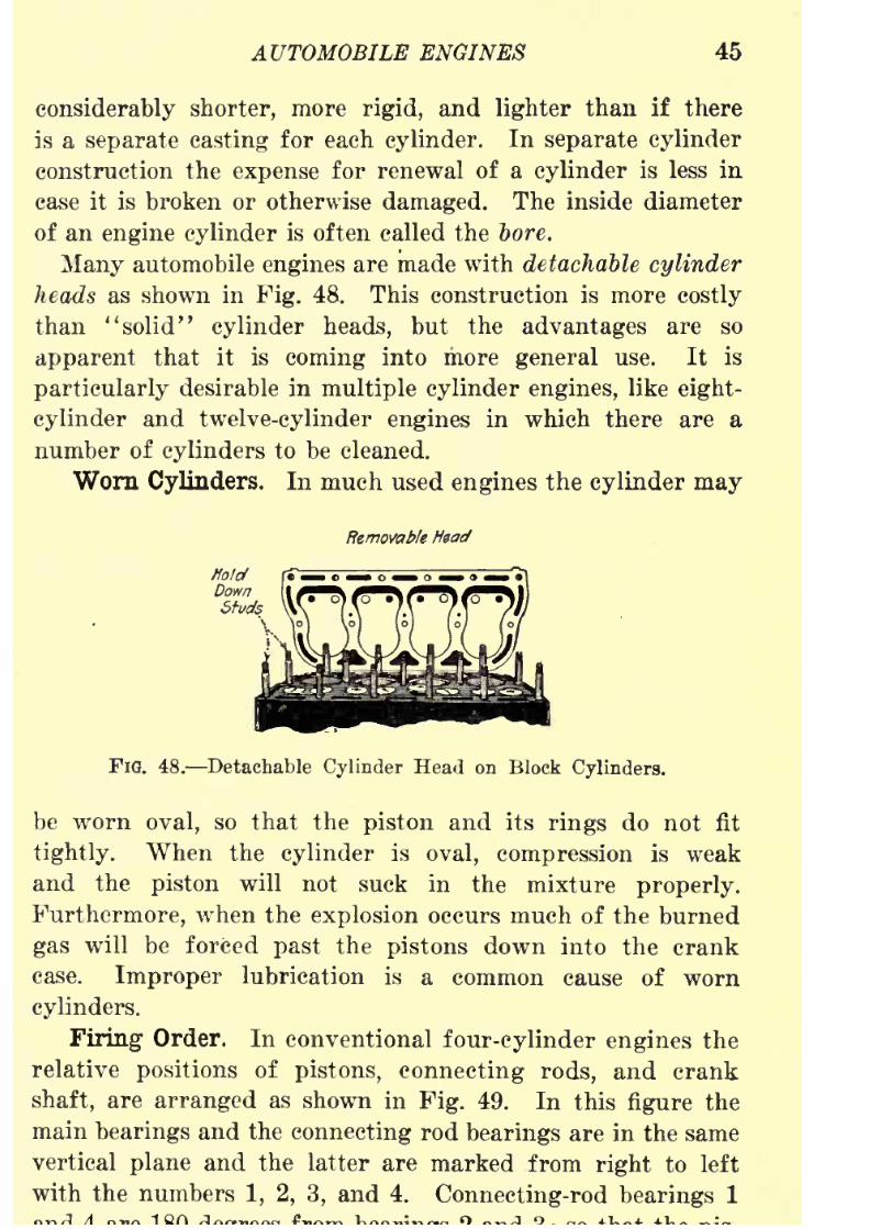
8/9/2019 (1921) Gasoline Automobiles
http://slidepdf.com/reader/full/1921-gasoline-automobiles 57/280
AUTOMOBILE ENGINES 45
considerably shorter, more rigid, and lighter than if there
is a separate casting for each cylinder. In separate cylinder
construction the expense for renewal of a cylinder is less in
case it is broken or otherwise damaged. The inside diameter
of an engine cylinder is often called the bore.
Many automobile engines are made with detachable cylinder
heads as shown in Fig. 48. This construction is more costly
than "solid" cylinder heads, but the advantages are so
apparent that it is coming into more general use. It is
particularly desirable in multiple cylinder engines, like eight-
cylinder and twelve-cylinder engines in which there are a
number of cylinders to be cleaned.
Worn Cylinders. In much used engines the cylinder may
Removable Head
FIG. 48. Detachable Cylinder Head on Block Cylinders.
be worn oval, so that the piston and its rings do not fit
tightly. When the cylinder is oval, compression is weak
and the piston will not suck in the mixture properly.
Furthermore, when the explosion occurs much of the burned
gas will be forced past the pistons down into the crank
case. Improper lubrication is a common cause of worncylinders.
Firing Order. In conventional four-cylinder engines the
relative positions of pistons, connecting rods, and crank
shaft, are arranged as shown in Fig. 49. In this figure the
main bearings and the connecting rod bearings are in the same
vertical plane and the latter are marked from right to left
with the numbers 1, 2, 3, and 4. Connecting-rod bearings 1
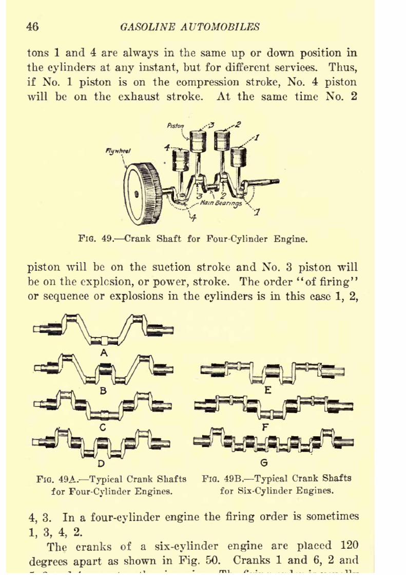
8/9/2019 (1921) Gasoline Automobiles
http://slidepdf.com/reader/full/1921-gasoline-automobiles 58/280
46 GASOLINE AUTOMOBILES
tons 1 and 4 are always in the same up or down position in
the cylinders at any instant, but for different services. Thus,
if No. 1 piston is on the compression stroke, No. 4 piston
will be on the exhaust stroke. At the same time No. 2
FIG. 49. Crank Shaft for Four-Cylinder Engine.
piston will be on the suction stroke and No. 3 piston will
be on the explosion, or power, stroke. The order "of firing"
or sequence or explosions in the cylinders is in this case 1, 2,
G
FIG. 49A. Typical Crank Shafts FIG. 49B. Typical Crank Shafts
for Four-Cylinder Engines. for Six-Cylinder Engines.
4, 3. In a four-cylinder engine the firing order is sometimes
1, 3, 4, 2.
The cranksof a
six-cylinder engineare
placed120
degrees apart as shown in Fig. 50. Cranks 1 and 6, 2 and

8/9/2019 (1921) Gasoline Automobiles
http://slidepdf.com/reader/full/1921-gasoline-automobiles 59/280
AUTOMOBILE ENGINES 47
1, 5, 3, 6, 2, 4 for the first shaft shown and 1, 4, 2, 6, 3, 5
for the other.
Horsepower of Automobile Engines. The usual method
of calculating the horsepower of automobile engines is by
the use of the 8. A. E. formula (Society of Automotive En-
gineers). This formula is intended to determine only approxi-
mately the useful, or brake horsepower (b.h.p.) of a high
speed gasoline engine. Briefly,
bore in inches X b re in inches X number cylinders
horsepower = _ .
=st ri
ring<
I-4-2-6-31
!
TlG. 50. Firing Orders in Six-Cylinder Engines.
If D represents the diameter, or bore, of the engine cylinders
in inches, and N represents the number of cylinders in the
engine, this formula is stated as follows:
D2N' 'P '
=2lT
=0 '
For instance, if an automobile has 6 cylinders and the bore
is 4 inches, the horsepower is,
4 V 4 V fi
=38.4 horsepower.
8/9/2019 (1921) Gasoline Automobiles
http://slidepdf.com/reader/full/1921-gasoline-automobiles 60/280
48 GASOLINE AUTOMOBILES
In abbreviated form the formula may be used as follows:
For 4 cylinder engines, b.h.p. =1.6JD*
"6
" " " =2.41)*
"8 " " " =3.2D*"
12" " "
This formula gives ratings much too low for modern
high-speed automobile engines, but gives with some degree
of accuracy the maximum horsepower of the most common
makes of four-cylinder engines, which are not intended to run
at more than about 1800 revolutions per minute. Modern
eight- and twelve-cylinder engines are intended to operate
at least fifty percent higher piston speeds than the above
formula was intended to cover.*
* Piston displacement is a term sometimes used when describing
the size of engine cylinders. It depends on the diameter of the cylinder
and the length of the piston stroke. Literally it means the space in the
cylinder swept through by the piston in going from one end of the
stroke to the other. It is calculated by multiplying the area of a circle
of the diameter of the inside of the cylinder in square inches by the
length of the piston stroke. The displacement is in cubic inches. The
clearance in an automobileengine
is thespace
inside thetop
of the
engine cylinder which the piston does not 'enter.
8/9/2019 (1921) Gasoline Automobiles
http://slidepdf.com/reader/full/1921-gasoline-automobiles 61/280
CHAPTER III
GASOLINE AND SUBSTITUTES
Gasoline. Nearly all automobiles.use gasoline for engine
fuel. The reason is that it vaporizes more easily than other
similar engine fuels. It is a product of the distillation of
crude oil (petroleum), which, when heated in large closed
retorts or stills, gives off vapor, which rises from the oil.
The vapor passes from the top of the retort into pipes or
cooling coils in which it is condensed. In this process of
crude oil distillation, the lighter vapors like gasoline,
naphtha, benzine, etc., are collected. With ordinary
atmospheric pressure in the retort, these lighter vapors will
be obtained when the crude oil is heated from about one
hundred to one hundred twenty-five degrees Fahrenheit.
If considerable pressure above atmospheric is maintained in
the retort by an air pump, the lighter vapors can be dis-
tilledoff
(called the "cracking," "Burton," or "Rittman"process) when the temperature is very much increased above
the limits for distillation at atmospheric pressure.
After the lighter vapors of the gasoline variety have
been collected and condensed, if heating is continued, there
is further rise in temperature in the retort, and heavier
vapors are collected which, when condensed, give in succes-
sion, according to the vaporizing temperature, kerosene,
light lubricating ("engine") oil, fuel oil (for steam boilers),
paraffine, etc. No definite percentages can be stated as to
the relative amounts of gasoline, kerosene, etc., from such
distillation, for much depends on the kind of crude oil used.
Some kinds of heavy crude oil from Middle Western and
Western States give relatively little gasoline with heating
at atmospheric pressure, but considerable amounts with
8/9/2019 (1921) Gasoline Automobiles
http://slidepdf.com/reader/full/1921-gasoline-automobiles 62/280
50 GASOLINE AUTOMOBILES
pressure distillation. This distillation process is usually
called oil refining.
Kerosene and Alcohol. For the same reason that kero-
sene does not vaporize readily in the distillation process,
it is difficult to use it in automobile engines as a substitute
for gasoline, which is easily vaporized. Alcohol is nearly
as difficult to vaporize as kerosene. Neither kerosene nor
alcohol can be easily vaporized without applying heat, and
cannot, therefore, be used satisfactorily for starting engines.
Gasoline Mixtures. A liquid fuel made up mostly of a
mixture of alcohol and gasoline has some advantages as
a substitute for gasoline in engines. It is a well known fact
that the efficiency of combustion in an engine can be con-
siderably increased by going above the present limited com-
pression. When gasoline of the ordinary commercial quality
is used in anengine,
the
compressionshould not much exceed
seventy-five pounds per square inch (gage) pressure, be-
cause, at a higher pressure, an explosive mixture of gasoline
and air is likely to be decomposed by the heat due to greater
compression, so that uncontrollable combustion results.* It
is equally well known that, if in the same kind of engine,
alcohol is used for fuel instead of gasoline, there is not the
same limit to compression, which can be carried to a much
higher pressure without serious disadvantages.
If a mixture of gasoline and alcohol, in about equal pro-
portions, is used for engine fuel, the mixture will combine
the advantages of both. The gasoline portion will vaporize
readily for starting the engine and the alcohol will make
it possible to use much higher compression pressures, withthe advantages of higher engine efficiency. Unless, however,
the head of the engine piston is made thicker, so as to reduce
the amount of space in the top of the engine cylinder provided
* The allowable limits of compression for very high grade gasoline
intended for high compression engines, such as are used for aeroplane
service, is about one hundred and twenty-five pounds per square inch
(gage). Ordinary compression pressures do not much exceed seventy

8/9/2019 (1921) Gasoline Automobiles
http://slidepdf.com/reader/full/1921-gasoline-automobiles 63/280
GASOLINE AND SUBSTITUTES 51
for the compression of the explosive mixture, the advantages
from the use of alcohol will not, of course, be obtained. To
use mixtures of gasoline and alcohol efficiently the compres-sion pressure should be raised to at least double the pressure
now used. A recommended gasoline and alcohol mixture
consists of forty percent alcohol, forty percent gasoline, and
twenty percent benzol. The benzol is added to make starting
easier. When this mixture is used in automobile engines,
there is practically no noticeable knocking in the engine due
to the high compression. Some of the large gasoline selling
stations do not furnish gasoline but instead a mixture of
heavy gasoline and benzol, which is a first class engine fuel
and is usually sold a little cheaper than standard gasoline.
Such mixtures are easily recognized, for the odor is unmis-
takable and is different from that of gasoline. For winter
service not much benzol can be used in gasoline mixtures as
it freezes at about fifteen degrees Fahrenheit. In very severe
climates, such mixtures might freeze solid in the gasoline
tank. It is claimed that when such gasoline mixtures are
used, a gasoline engine runs more smoothly than when
ordinary commercial gasoline alone is used. Mixtures of
gasoline and benzol are commonly called "doped" gasoline.
The addition of benzol to gasoline gives it a "sweet" odor.
Gasoline made by the cracking process, especially if it has
been stored a long while, has a disagreeable odor.
The principal advantage claimed for a gasoline and
alcohol mixture is that the maximum power of an engine
is increased about five
percentwith the usual
gasolinecom-
pression, and about fifteen percent with the compression
increased to about one hundred and fifty pounds per square
inch. At maximum power, the fuel consumption per brake
horsepower, when a mixture of gasoline and alcohol is used
and the engine is operated at high compression, is ten percent
less than with gasoline at normal engine compression.
Rate of Production of Gasoline. The present production
of is in
8/9/2019 (1921) Gasoline Automobiles
http://slidepdf.com/reader/full/1921-gasoline-automobiles 64/280
52 GASOLINE AUTOMOBILES
automobiles and tractors put on the market each year, it
is likely that the amount which can be allotted for each
automobile or tractor must be reduced in the near future.
in the distillation of crude oil, between twenty and twenty-
five percent of the product on the average is gasoline, twelve
percent is kerosene, about fifty percent is fuel oil, and the
rest is lubricating oil, paraffin, vaseline, carbon, etc. About
thirty percent of the gasoline now produced comes from
the portion that was formerly called kerosene. All the kero-
sene cannot be taken to increase the gasoline supply because
ninety percent of the world is still lighted with kerosene
lamps, and about ninety-five percent of the world does not
know what electric lights are. The kerosene market, there-
fore, is still an important factor. The price of kerosene will
probably soon be nearly the same as that of gasoline.
Knocking Caused by Engine FueL The real problemtoday in automobile engineering is to eliminate the carbon
and the knocking in the engine. For years engineers have
been trying to find out the cause of knocking in gasoline
engines when there is carbon in the cylinders. Knocking in
the engine cylinders used to be called pre-ignition, by which
is meant ignition of the explosive mixture near the beginning
of the compression stroke, thought to be caused by red-hot
particles of carbon on the inside surface of the cylinders
setting the explosive mixture afire prematurely. Chemical
analysis of gasoline shows that it is made up of hydrogen
and carbon. Now when gasoline is imperfectly vaporized, it
breaks up and bums only the hydrogen. The carbon is left
behind to settle on the inside surfaces of the cylinders. Carbon
is one of the best possible heat insulators. "Wool ranks first
as a heat insulator, and finely divided carbon is second of the
ordinary materials. As long as the temperature of combus-
tion is below a certain point, the gasoline will burn normally
and without noise.
If the temperature of the incoming air is reduced to ten
degrees below the Fahrenheit zero, an engine will run well

8/9/2019 (1921) Gasoline Automobiles
http://slidepdf.com/reader/full/1921-gasoline-automobiles 65/280
GASOLINE AND SUBSTITUTES 53
inch. The refrigerated air simply prevents the temperature
of combustion from going above the critical point at which
the kerosene or gasoline breaks up. The only reason a gaso-
line automobile engine runs better with all the carbon removed
is that the cooling system is more active and takes away
heat rapidly enough at the time of highest temperature to
keep the gasoline from breaking up. As soon, however, as
there is a little deposit of carbon, the cooling system is not
so active and the temperature gets too high.*
If the temperature of combustion is kept from rising
above the point at which the gasoline breaks up, perfect
combustion is possible and gasoline engines will run without
carbon accumulations and without knocking in the cylinders.
Regulating Combustion by Additions to the Fuel. Asmall quantity of ordinary aniline added to the gasoline used
in a gasoline engine will entirely change its operation. Theaddition of only one percent of aniline to the gasoline used
in an automobile engine which does not travel well on steep
hills and is troublesome on account of knocking will change
the running of the engine to give almost perfect operation.
Schroeder, when he tried to make his great altitude flights
in 1919, at first reached only 32,000 feet and could go no
higher with ordinary gasoline. Later, he mixed two or three
percent of aniline with the gasoline and went up for a record-
breaking flight, and had no trouble with the explosive mixture.
The increase in gasoline supply must come from the
present ''fuel" part of crude oil, which is now about fifty
percent. At least eighty percent of1
this can be refined into
*This temperature change is relatively large for a slight change in
cooling, because the specific heat of the gases is so low; that is, the
amount of heat which is required to raise a volume of gas through a
degree is so low that just a little more energy, plus or minus, means a
great raising or lowering of the temperature curve, and a few heat units
added to the gas will raise the temperature many degrees. When the
temperature reaches the point where gasoline breaks up, the combustionis fifty or sixty times as fast as in a normal explosion, and it is the im-
8/9/2019 (1921) Gasoline Automobiles
http://slidepdf.com/reader/full/1921-gasoline-automobiles 66/280
54 GASOLINE AUTOMOBILES
water-white oil resembling kerosene, which makes an excellent
engine fuel, if used in such a way as to prevent the breaking
up of the fuel.
Aniline, iodine, or some other similar ingredient, when
mixed with gasoline, will break up at a lower temperature
than the gasoline, and by thus absorbing heat energy it keeps
down the temperature of the gasoline. For example, if a
mixture of water and alcohol is put on a stove, the tempera-
ture of the water cannot be raised while any alcohol remains,
because the alcohol will evaporate and keep the temperature
down. Aniline breaks up at about one thousand or eleven
hundred degrees Fahrenheit, and in the process of breaking
up absorbs considerable heat.
If the automobile manufacturers could get the chemical
industry to increase the coal tar production of the country,
so that aniline could be sold at two dollars per gallon, it
would not be too expensive for general use. If the use of
such gasoline and aniline mixtures became common, the com-
pression of automobile engines could be safely raised to one
hundred pounds per square inch, which would almost double
the efficiency of normal running. Automobile engineers pre-
dict that within five years gasoline engines will run inde-
finitely without any carbon trouble on almost any kind of
petroleum fuel. Even if the addition of antiknocking
chemicals increases the cost of gasoline two or three cents
per gallon, the method would be economical because of the
saving of fuel and of the cost of carbon removal.
Hydrometers.In
orderto.
determine the qualityof
gaso-line, as to whether it is a light or a heavy grade, a sample
may be conveniently tested with a small glass instrument
called a hydrometer. A typical hydrometer is shown in Fig.
51, as it appears when immersed in gasoline and in kerosene.
There are etched numbers on the stem, reading upward. These
numbers on a hydrometer for gasoline testing are called
degrees of Baume test, named for the man who introduced
this method of These
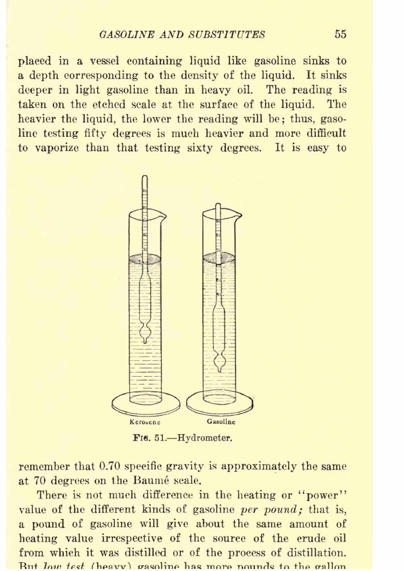
8/9/2019 (1921) Gasoline Automobiles
http://slidepdf.com/reader/full/1921-gasoline-automobiles 67/280
GASOLINE AND SUBSTITUTES 55
placed in a vessel containing liquid like gasoline sinks to
a depth corresponding to the density of the liquid. It sinks
deeper in light gasoline than in heavy oil. The reading is
taken on the etched scale at the surface of the liquid. The
heavier the liquid, the lower the reading will be; thus, gaso-
line testing fifty degrees is much heavier and more difficult
to vaporize than that testing sixty degrees. It is easy to
Fis. 51. Hydrometer.
remember that 0.70 specific gravity is approximately the same
at 70 degrees on the Baume scale.
There is not much difference in the heating or "power"
value of the different kinds of gasoline per pound; that is,
a pound of gasoline will give about the same amount of
heating value irrespective of the source of the crude oil
from which it was distilled or of the process of distillation.

8/9/2019 (1921) Gasoline Automobiles
http://slidepdf.com/reader/full/1921-gasoline-automobiles 68/280
56 GASOLINE AUTOMOBILES
assuming, of course, equally good vaporization and combus-
tion low test gasoline will take an automobile farther per
gallon
than the
high
test kind.
Gasoline Tanks. Gasoline for use in automobile engines
is usually carried in a tank holding from ten to twenty
gallons, placed in most automobiles at the rear between the
back springs, but there are some automobiles with high-hung
bodies in which the gasoline tank is placed under the front
seat, and in still others, under the dash behind the engine.
In the most common system of gasoline supply, which is, in
fact, used in at least eighty percent of the automobiles with
rear tanks, the principle of vacuum or suction, as explained
in the following paragraphs, is applied to bring the gasoline
to the engine.
Vacuum Gasoline Feed System. A commonly used device
to draw gasoline from a tank located below the level of thecarbureter is the Stewart vacuum apparatus shown in Fig.
52. The method of attachment of this system in an automo-
bile is shown in Fig. 53. The auxiliary tank is placed higher
than the intake pipes of the engine so that it is necessary
to draw the gasoline into it from the main tank by suction.
The suction of the automobile engine is used to draw the
gasoline from the main tank at the rear of the automobile
to the auxiliary tank, which acts really as a vacuum pump.From the auxiliary tank the gasoline flows to the engine by
gravity. By this system all the advantages of a simple gravity
system as explained later are obtained with a relatively simple
apparatus, which is usually mounted in front of the dash,
at one side of the engine. There must be a small vent hole
in the filling plug of the main tank at the rear so that the
pressure inside that tank will be atmospheric.
The auxiliary vacuum tank is divided into two chambers;
the upper one is the filling chamber, marked F. The lower
one is the emptying chamber E. The two chambers are
separated by a
diaphragmwhich has a
downward projectingspout P. The upper chamber has a float L, which controls

8/9/2019 (1921) Gasoline Automobiles
http://slidepdf.com/reader/full/1921-gasoline-automobiles 69/280
GASOLINE AND SUBSTITUTES 57
main tank at the rear of the automobile, discharges into
the upper chamber F. An air pipe T extends from the top
of this chamber to the intake pipe of the engine; the enginesuction for drawing the gasoline from the rear tank is exerted
through this pipe. The lower chamber is used to supply
FIG. 52. Vacuum Gasoline Feed Tank.
gasoline to the engine by gravity, and must be, therefore,
under atmospheric pressure at all times so that the flow from
it through the pipe to the carbureter will be continuous.
Since the bottom of this gravity chamber is located at a
higher level than the carbureter on the engine, there will
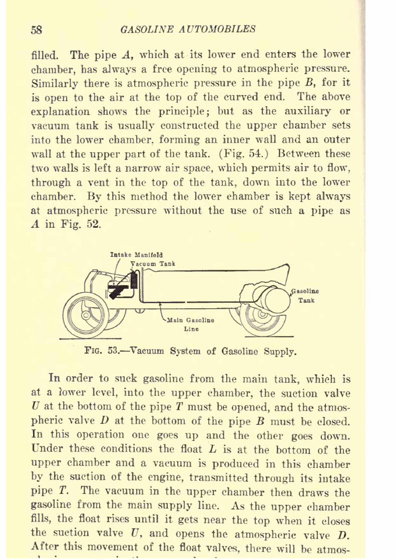
8/9/2019 (1921) Gasoline Automobiles
http://slidepdf.com/reader/full/1921-gasoline-automobiles 70/280
58 GASOLINE AUTOMOBILES
filled. The pipe A, which at its lower end enters the lower
chamber, has always a free opening to atmospheric pressure.
Similarly thereis
atmospheric pressurein the
pipe B,for it
is open to the air at the top of the curved end. The above
explanation shows the principle; but as the auxiliary or
vacuum tank is usually constructed the upper chamber sets
into the lower chamber, forming an inner wall and an outer
wall at the upper part of the tank. (Fig. 54.) Between these
two walls is left a narrow air space, which permits air to flow,
through a vent in the top of the tank, down into the lower
chamber. By this method the lower chamber is kept always
at atmospheric pressure without the use of such a pipe as
A in Fig. 52.
Intake Manifold
rsruum Tank
FIG. 53. Vacuum System of Gasoline
Supply.
In order to suck gasoline from the main tank, which is
at a lower level, into the upper chamber, the suction valve
U at the bottom of the pipe T must be opened, and the atmos-
pheric valve D at the bottom of the pipe B must be closed.
In this operation one goes up and the other goes down.
Under these conditions the float L is at the bottom of the
upper chamber and a vacuum is produced in this chamber
by the suction of the engine, transmitted through its intake
pipe T. The vacuum in the upper chamber then draws the
gasoline from the main supply line. As the upper chamber
fills, the float rises until it gets near the top when it closes
the suctionvalve U, and opens the atmospheric valve D.
After this movement of the float valves, there will be atmos-
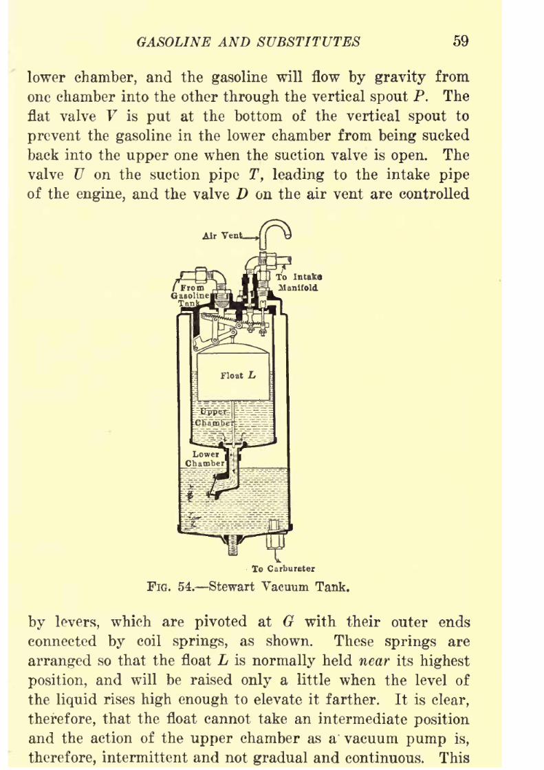
8/9/2019 (1921) Gasoline Automobiles
http://slidepdf.com/reader/full/1921-gasoline-automobiles 71/280
GASOLINE AND SUBSTITUTES 59
lower chamber, and the gasoline will flow by gravity from
one chamber into the other through the vertical spout P. The
flat valve V is put at the bottom of the vertical spout to
prevent the gasoline in the lower chamber from being sucked
back into the upper one when the suction valve is open. The
valve U on the suction pipe T, leading to the intake pipe
of the engine, and the valve D on the air vent are controlled
Air Vent.,
To Carbureter
FIG. 54. Stewart Vacuum Tank.
by levers, which are pivoted at G with their outer ends
connected by coil springs, as shown. These springs are
arranged so that the float L is normally held near its highest
position, and will be raised only a little when the level of
the liquid rises high enough to elevate it farther. It is clear,
therefore, that the float cannot take an intermediate position
and the action of the upper chamber as a' vacuum pump is,
therefore, intermittent and not gradual and continuous. This

8/9/2019 (1921) Gasoline Automobiles
http://slidepdf.com/reader/full/1921-gasoline-automobiles 72/280
60 GASOLINE AUTOMOBILES
upper chamber may be under atmospheric pressure part of
the time, when the gasoline will flow by gravity from the
upper chamber to the lower. When thelevel of the
gasoline
drops to a certain point, the float L drops slightly from its
elevated position, and by its movement opens the valve U
on the suction line and closes the valve D on the atmospheric
line. With the valves in this position, the suction of the
engine again causes a flow of gasoline from the main supply
tank. As soon as the level of the gasoline rises so as to
elevate the float, the valves have the opposite movement, which
closes the suction pipe and opens the air vent.
Sometimes it happens, if an automobile is allowed to stand
for a long time with the engine shut off, that because of a
leakage in the system, the vacuum tank becomes empty. But
this tank can usually be filled again with enough gasoline
for starting when the engine is turned over four or five
revolutions with the throttle valve completely closed. A metal
screen is put at the end of the gasoline supply line 8, near
where it enters the vacuum tank, to prevent sediment or
foreign material from entering the float chamber.
An emergency filling plug Q, when unscrewed and taken
out, makesit
possible to pour gasoline through the hole fromwhich the plug is taken. For this filling a small funnel
should be used. At other times, this plug should be screwed
tightly so that there can be no air leakage into the upper
chamber, for air leakage would prevent the drawing of
gasoline from the main tank by engine suction. For cold
weather service, this system has the advantage that the
auxiliary tank is near the engine and the gasoline going
through it will be heated on the way to the carbureter; in
this way, vaporization is improved.
Sometimes the float L will leak and fill with gasoline. If
it does the valves U and D will not operate, and there will
be continuous suction, so that the two chambers will fill com-
pletely with gasoline, and finally the pipe leading to the intakeof the engine will be partly filled. The engine will then

8/9/2019 (1921) Gasoline Automobiles
http://slidepdf.com/reader/full/1921-gasoline-automobiles 73/280
GASOLINE AND SUBSTITUTES 61
In that case, the cover of the tank (Fig. 55) should be
taken off at the top so that the float can be taken out
and repaired. If this trouble with the float should occur
when the automobile is "on the road," it is best to take
off the cover very carefully, fill the tank with gasoline,
and then replace the cover loosely. The auxiliary tank will
then be used as a gravity tank. When the tank is empty,
the cover can be taken off and the tank refilled.
Gravity Gasoline Feed System. The gravity system of
gasoline supply consists simply of a gasoline tank under
one of the seats of the automobile and a pipe for carrying
the gasoline by gravity or by its own weight to the car-
bureter. Under the tank there is a sediment chamber. Dirt
FIG. 55. Top of Stewart Tank.
and water being heavier than gasoline will settle at the
bottom and can be cleaned out through the pet cock. Water
is apt to accumulate in the bottom of the tank, and, if it
freezes in cold weather, the gasoline supply may be shut
off. If this happens, it is wiser to put hot cloths on the
bottom of the tank and on the gasoline pipe rather than
to take the risk of using a flame for heating.
Pressure Gasoline Feed System. Another system used
is the pressure system. Not many automobiles use this
system; but some of the most expensive automobiles are
equipped this way. The tank is at the rear of the auto-
mobile, as it is in the Stewart vacuum system, but withthe difference that it is air tight. The Packard, Pierce,
8/9/2019 (1921) Gasoline Automobiles
http://slidepdf.com/reader/full/1921-gasoline-automobiles 74/280
62 GASOLINE AUTOMOBILES
the gasoline tank must be screwed on tightly because air
pressure on the top of the gasoline in the tank forces the
gasoline
into the carbureter. A small air pump, driven by
the engine, delivers air under pressure through a pipe enter-
ing the top of the gasoline tank.
After an automobile has been standing several hours,
there will not be enough pressure in the tank to force the
gasoline into the carbureter;and then a hand pump, intended
for emergency use and placed near the driver's seat, is used
to provide enough pressure for starting; but it is necessary
first to open a valve below this pump, so that the air can
be pumped into the tank. Usually the handle of a valve
on any automobile hangs down when the valve is closed.
Leaks in Air Lines. If there is a slight leak in any part
of an air line for pressure or vacuum, the gasoline supply
to the carbureter will probably be stopped. Do not testfor air leaks by holding a match to the leak. That is too
dangerous around an automobile. It is best to take a little
soapy water and put it on the places where there are likely
to be leaks. Bubbles will then form at the leak. Chewing
gum or shellac may be put over air leaks until the automobile
can be taken to a repair shop.
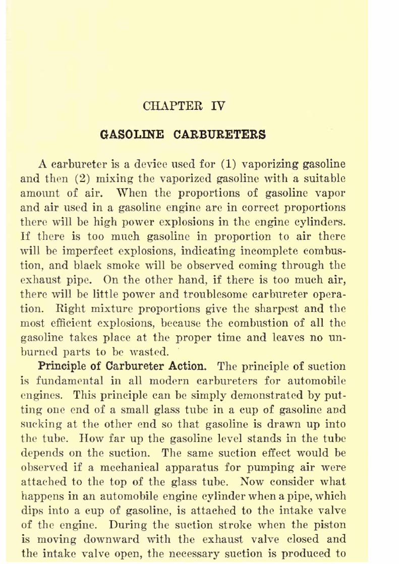
8/9/2019 (1921) Gasoline Automobiles
http://slidepdf.com/reader/full/1921-gasoline-automobiles 75/280
CHAPTER IV
GASOLINE CARBURETERS
A carbureter is a device used for (1) vaporizing gasoline
and then (2) mixing the vaporized gasoline with a suitable
amount of air. When the proportions of gasoline vapor
and air used in a gasoline engine are in correct proportions
there will be high power explosions in the engine cylinders.
If there is too much gasoline in proportion to air there
will be imperfect explosions, indicating incomplete combus-
tion, and black smoke will be observed coming through theexhaust pipe. On the other hand, if there is too much air,
there will be little power and troublesome carbureter opera-
tion. Right mixture proportions give the sharpest and the
most efficient explosions, because the combustion of all the
gasoline takes place at the proper time and leaves no un-
burned parts to be wasted.
Principle of Carbureter Action. The principle of suction
is fundamental in all modern carbureters for automobile
engines. This principle can be simply demonstrated by put-
ting one end of a small glass tube in a cup of gasoline and
sucking at the other end so that gasoline is drawn up into
the tube. How far up the gasoline level stands in the tube
depends on the suction. The same suction effect would be
observed if a mechanical apparatus for pumping air were
attached to the top of the glass tube. Now consider what
happens in an automobile engine cylinder when a pipe, which
dips into a cup of gasoline, is attached to the intake valve
of the engine. During the suction stroke when the piston
is moving downward with the exhaust valve closed andthe intake valve open, the necessary suction is produced to

8/9/2019 (1921) Gasoline Automobiles
http://slidepdf.com/reader/full/1921-gasoline-automobiles 76/280
GASOLINE AUTOMOBILES
into the engine cylinder. An intake pipe for this purpose
might be arranged with two branches as shown in Fig. 56,
one of which dips into gasoline and the other is
opento
the air. By means of such a device the suction of the engine
piston will suck a mixture of gasoline and air into the
cylinder. This device suggests one way to put an explosive
'Spark Plug
Exhaust
Valve-E
Intake
Valve-/
FIG. 56. Simple Carbureter.
mixture into the engine cylinder. It is a kind of carbureter.
All gasoline carbureters have similarly branched passages
although not so simply arranged. Through one branch air
is drawn, and through the other gasoline vapor.
Unless the supply of liquid gasoline is arranged to givea practically constant level in the gasoline cup (Fig. 56),the flow of
gasoline vapor into the intake pipe of the enginewill be irregular. If the gasoline level is lowered, the gaso-
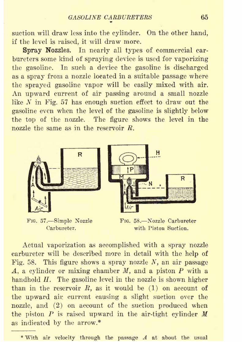
8/9/2019 (1921) Gasoline Automobiles
http://slidepdf.com/reader/full/1921-gasoline-automobiles 77/280
GASOLINE CARBURETERS 65
suction will draw less into the cylinder. On the other hand,
if the level is raised, it will draw more.
SprayNozzles. In
nearlyall
typesof commercial car-
bureters some kind of spraying device is used for vaporizing
the gasoline. In such a device the gasoline is discharged
as a spray from a nozzle located in a suitable passage where
the sprayed gasoline vapor will be easily mixed with air.
An upward current of air passing around a small nozzle
like N in Fig. 57 has enough suction effect to draw out the
gasoline even when the level of the gasoline is slightly below
the top of the nozzle. The figure shows the level in the
nozzle the same as in the reservoir R.
FIG. 57. Simple Nozzle
Carbureter.
FIG. 58. Nozzle Carbureter
with Pistoa Suction.
Actual vaporization as accomplished with a spray nozzle
carbureter will be described more in detail with the help of
Fig. 58. This figure shows a spray nozzle N, an air passage
A, a cylinder or mixing chamber M, and a piston P with ahandhold H. The gasoline level in the nozzle is shown higher
than in the reservoir R, as it would be (1) on account of
the upward air current causing a slight suction over the
nozzle, and (2) on account of the suction produced when
the piston P is raised upward in the air-tight cylinder Mas indicated by the arrow.*
* With air velocity through the passage A at about the usual
8/9/2019 (1921) Gasoline Automobiles
http://slidepdf.com/reader/full/1921-gasoline-automobiles 78/280
06 GASOLINE AUTOMOBILES
Float Regulator. A device for regulating the amount
of gasoline going into the reservoir R in a carbureter like
Fig. 58 is necessary if the gasoline is to be at constant level.
For this purpose a float is connected to a small valve, called
a float valve, which shuts off the flow from the gasoline supply
pipe. The float device is self-adjusting and the valve con-
nected to the float shuts off the flow of gasoline when the
level in the reservoir rises nearly to the top of the nozzle. A
carbureter could be made to operate with the float arranged
to have the established level of the liquid as high as the
top of the nozzle, but the float is always set to shut off at
a lower level so that there will be a margin of safety in case
of inaccurate or sluggish operation of the float and valve,
which might cause an excessive flow of gasoline from the
nozzle. Even with the best devices this sometimes happens
when the float or valve "sticks" and allows the gasoline to
rise in the float chamber slightly above the established level
so that it overflows from the nozzle. A low gasoline level
in the nozzle atso prevents dripping from the nozzle when
the engine is "idle" and is not in a level position, or when
excessive vibration might cause the gasoline to overflow into
the air passage A.
Float-Feed Carbureter. Fig. 59 shows a very simple typeof carbureter in which the flow or "feed" of gasoline is
regulated by a float F. The liquid fuel supply enters at Gand flows through the float valve FV into the float chamber C,
from which some of the gasoline flows into the tube U leading
to the spray nozzle N. When the gasoline level in the float
chamber rises and is
onlyabout
one-sixteenth inch from thetop of the spray nozzle the float closes the attached valve FV,
be a considerable difference in level between the top of the nozzle andthe surface of the liquid in the reservoir B before the gasoline sprayceases. It may be as much even as one and one-half inches, and witha flow of gasoline once established the spray will usually continue until
the difference in level is as much as two inches. Theseunusual condi-tions result sometimes when the gasoline supply for an engine is nearly
exhausted.
8/9/2019 (1921) Gasoline Automobiles
http://slidepdf.com/reader/full/1921-gasoline-automobiles 79/280
GASOLINE CARBURETERS 67
and prevents the gasoline from rising higher. The air supply
enters through the passage A and passes up in the direction
of the arrow into the mixing chamber M,where the air mixes
with the gasoline vapor discharging from the spray nozzle N.
The top of the mixing chamber M is made so that there will
be air tight connections to the intake pipe of the engine.*
The engine piston on its suction or intake stroke produces
the necessary suction to draw the explosive mixture of gasoline
vapor and air from the mixing chamber into the engine
cylinder.
FIG. 59. Simple Carbureter
with Float Feed.
FIG. 60. Carbureter with
Auxiliary Air Valve.
In the operation of the carbureter, the removal of gasoline
through the nozzle N lowers the level in the float chamber C
and causes the float F to descend enough to open the float
valve FV, which allows more gasoline to enter. In this waya nearly constant level can be maintained in the float chamber
and also in the spray nozzle.
Auxiliary Air Valve. When the speed of an engine
increases, the suction produced by the piston in the intake
pipe increases in proportion. Increased suction will propor-
tionally increase the amount of gasoline sucked out of the
spray nozzle of the carbureter. On the other hand, increased
* The float chamber should not be made air tight where the rod Bconnecting the float with the float valve FV passes through the cover

8/9/2019 (1921) Gasoline Automobiles
http://slidepdf.com/reader/full/1921-gasoline-automobiles 80/280
68 GASOLINE AUTOMOBILES
suction does not increase proportionally the amount of air
passing through the air passage. Gasoline is a liquid and
its particles "hang together," when pulled by suction; but
air is an elastic and "expansive" fluid with no tendency for
the particles to "hang together." Because of this difference,
the amounts of air and of gasoline sucked into a carbureter
are not in the same proportions at different engine speeds.
For example, an average size of automobile engine will take
in through the carbureterabout^ fifty pounds of air and five
pounds of gasoline per hour when running at a speed of five
hundred revolutions per minute. If the speed is increased to
one thousand revolutions per minute, the amount of gasoline
will be ten pounds (increased in proportion to the speed) ;
but the amount of air will be only about eighty pounds instead
of one hundred pounds as it would be if the amount of air
increased in proportion to the speed. If the parts of thesimple form of carbureter already explained will give an
efficient mixture of gasoline and air at an engine speedof five hundred revolutions, the mixture will not be right
at one thousand revolutions per minute^ In other words,
at the higher speeds, the mixture will be too "rich" in gaso-
line. Also, if the mixture is right for high speeds it will be
wrong for low speeds. All simple carbureter devices like
the one shown in Fig. 59 will give the engine an explosive
mixture richer in gasoline when air passes around the spraynozzle at high velocity and high suction than when at low
'
velocity and low suction.(In other words, increasing the
engine speed increases also the percentage of gasoline in the
explosive mixture. All kinds of spray nozzle carbureters
must, therefore, use some adjusting device, which should be
automatic. Such a device is called an auxiliary air valve\
of which a typical example is marked AV in Fig. 60^ This \
auxiliary air valve is provided with a spiral spring X of
sufficient strength to hold it closed at low engine speeds,when there is little suction in the
mixing chamber M. In-creased engine speed produces greater suction so that this

8/9/2019 (1921) Gasoline Automobiles
http://slidepdf.com/reader/full/1921-gasoline-automobiles 81/280
GASOLINE CARBURETERS 69'
speed. It will be open a little at moderate speeds, and more
at high speeds, permitting additional air flow into the mixing
chamber M. This additional air
supply,as the
speedof the
engine is increased, has the effect of reducing the suction
in the air passage A in proportion to the amount of opening
of the valve. A plug K at the bottom of the float chamber
can be removed for cleaning out water and dirt carried in
from the gasoline supply pipe G. A small cock H is at the
bottom of the spray-nozzle tube which is intended for the
rapid removal of any accumulation of water or for tapping
small quantities of gasoline from the carbureter for engine
priming, cleaning, etc.
Priming a Carbureter. An explosive mixture, very rich
in gasoline is usually necessary, especially in cold weather,
to start a gasoline engine. Conditions for combustion are
very unfavorable when the engine is cold and when it is
turning over slowly for starting. One reason is that there
is a leakage of the compression pressure between the inside
surface of the engine cylinder and the piston during the
relatively long time required for a slow speed stroke. An-
other reason is that the heat developed by the compression
of theexplosive
mixture is
largelylost
(dissipated)at slow
speed of starting. The result is that only the most easily
evaporated part of the gasoline can be vaporized at the time
of starting an engine, and this easily vaporized 'part is only
a small percentage of that discharged from the spray nozzle
of the carbureter. It is, therefore, necessary to take a large
quantity of gasoline into the engine cylinders to secure enough
of the easily vaporized kind to start combustion. One wayto obtain an explosive mixture very rich in gasoline is to
depress the float rod R (Fig. 60) by hand, so that a small
quantity of gasoline will overflow from the spray nozzle into
the air passage A. Gasoline exposed in this way in the air
passage will be readily vaporized and mixed with the entering
air so that the engine will receive a "rich" explosive mixtureat the slow speed of starting, whether the engine is turned
8/9/2019 (1921) Gasoline Automobiles
http://slidepdf.com/reader/full/1921-gasoline-automobiles 82/280
70 GASOLINE AUTOMOBILES
Somewhat different devices for priming carbureters will be
explained in the descriptions of other carbureters.
It is dangerous to let very much gasoline discharge from
the spray nozzle of a carbureter by priming when the engine
is very cold, because under these conditions, a slow-burning
ignition flame sometimes comes back through the intake valves
into the carbureter, and if a puddle of gasoline has accumu-
lated, there is danger of having a troublesome fire. There
is the same danger of a fire* in the carbureter if the engine
is turned over a number of times without getting an explosion
in the cylinders either because the electric switch for ignition
has not been turned or because the ignition device is defective.
Every revolution of the engine pumps more gasoline into
the cylinders and this gasoline is left condensed on the pistons
and on the tops of the cylinders. The engine will probably
start when the trouble with the ignition has been correctedand the accumulation of gasoline has evaporated. Sometimes
when a cold engine is to be started and the usual methods
of priming the carbureter are ineffective, a teaspoonful of
gasoline put into each of the engine cylinders will serve to
start the engine. "When the engine does not start after this
"treatment" there is probably some defect in the ignition.
If, however, too much gasoline is put into the cylinders for
priming, the mixture will be too rich for engine operation.
The need is then for more air rather than more gasoline.
Regulated Nozzle Carbureters. The carbureter shown in
Fig. 60 has the float valve rigidly attached to the float so
that when the float is raised, the valve will be raised an
equal amount. Another arrangement of the float and valveis shown in Fig. 61 in which the float valve FV is at the
side of the float F, which is made of cork and is in the shapeof a horseshoe. The short lever L is fastened on one side
to the top of the float and at the other end is forked to fit
Water should not be poured on a gasoline fire. It is best to use
the spray of chemicals from a good kind of fire extinguisher. Such a
fire can be smothered by throwing blankets, sand, or dirt over the
8/9/2019 (1921) Gasoline Automobiles
http://slidepdf.com/reader/full/1921-gasoline-automobiles 83/280
GASOLINE CARBURETERS 71
around the rod or stem attached to the float valve FV. This
lever is supported on a horizontal pin at /. When the left-
hand end of the lever is pressed downward by the weight
of the float (when the gasoline level falls) the other end of
the lever, which is attached to the float valve FV is raised
and permits gasoline from the supply pipe G to flow into the
float chamber C.
The carbureter shown in Fig. 61 has a mechanical means
for regulating the flow of gasoline through the spray nozzle.
The spray nozzle N extends into the middle of the mixing
ToEngine
Cylinder
FIG. 61. Regulated Nozzle Carbureter.
chamber M so that it is near the center of the float chamber.
This arrangement has the advantage that the flow of gasoline
through the nozzle is not much affected by either endwise or
sidewise tilting. The needle valve or pointed stem P in the
opening in the spray nozzle N is used to regulate the amount
of the gasoline going into the mixing chamber.* The main
*Sometimes the needle valve or pointed stem is at such an angle that
by lengthening the stem it can be extended to reach to the dash board
or instrument board. It may then be fitted with a handle intended to
be turned slightly when starting the engine, in order to get a mixture
8/9/2019 (1921) Gasoline Automobiles
http://slidepdf.com/reader/full/1921-gasoline-automobiles 84/280
72 GASOLINE AUTOMOBILES
air supply enters through the holes shown in the bottom of
the carbureter and goes into the air passage A and then
past the spray nozzle into the mixing chamber M. The
amount of opening of the auxiliary air valve AV is propor-
tional to the engine speed. The auxiliary air current has the
effect at high engine speeds mainly by reducing the suction
of checking the flow of gasoline from the spray nozzle. The
butterfly throttle valve, as shown to the left of M, regulates the
quantity of the mixture of gasoline and air going to the engine
cylinders. A throttle valve of this kind is simply a small
damper similar to those in the smoke pipes of furnaces and
stoves. It is connected to the throttle lever on the steering
column and also to the foot pedal called the accelerator. Mov-
ing the throttle lever by hand or depressing the accelerator
with the foot opens this valve and allows more explosive
mixture to enter the engine cylinders. The throttle valve
thus regulates the speed of the engine.
Symbols for Carbureters. In the following descriptions
of carbureters the symbols given below will be used to
designate the important parts. Keeping these in mind, it
should be possible to understand the operation of any car-
bureter marked with these symbols by casual examination
of the figures going with the description. The following
symbols are used to mark the figures in this chapter:
A Air Intake.
AA Auxiliary Air Intake, if without auxiliary air valve.
AN Auxiliary Gasoline Nozzle.
AV Auxiliary Air Valve (for high speed adjustment).
C Gasoline Chamber (also called float chamber).D Dash Pot (to steady valve action).
E Exhaust Gas Connection.
F Float in Gasoline Chamber.
FV Float Valve.
G Gasoline Supply Pipe.
J Gasoline Pool or "Puddle."L Lever on Throttle Valve T.
M Mixing Chamber.
N Gasoline Nozzle.
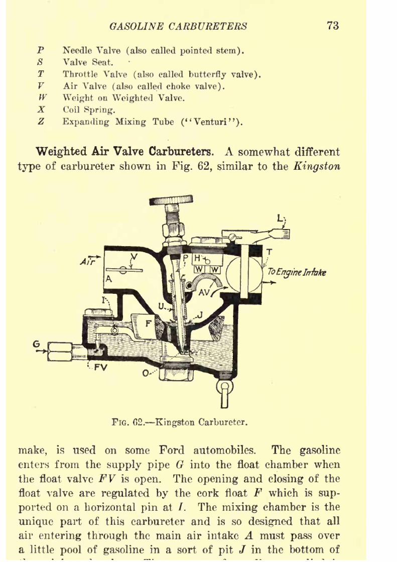
8/9/2019 (1921) Gasoline Automobiles
http://slidepdf.com/reader/full/1921-gasoline-automobiles 85/280
GASOLINE CARBURETERS 73
P Needle Valve (also called pointed stem).
8 Valve Seat.
T Throttle Valve (also called butterfly valve).
V Air Valve (also called choke valve).W Weight on Weighted Valve.
X Coil Spring.
Z Expanding Mixing Tube ("Venturi").
Weighted Air Valve Carbureters. A somewhat different
type of carbureter shown in Fig. 62, similar to the Kingston
Air
ToEngineIntake
FV
FIG. 02. Kingston Carbureter.
make, is used on some Ford automobiles. The gasoline
enters from the supply pipe G into the float chamber when
the float valve FV is open. The opening and closing of the
float valve are regulated by the cork float F which is sup-
ported on a horizontal pin at /. The mixing chamber is the
unique part of this carbureter and is so designed that all
air entering through the main air intake A must pass overa little pool of gasoline in a sort of pit / in the bottom of

8/9/2019 (1921) Gasoline Automobiles
http://slidepdf.com/reader/full/1921-gasoline-automobiles 86/280
74 GASOLINE AUTOMOBILES
regulated by the position of the needle valve or pointed
stein P which, by adjusting the size of the opening in the
submergednozzle at controls the level of gasoline in the
pool. Obviously, more gasoline will be taken up by the air
when the level is high than when low. On account of having
such a gasoline pool, this kind of carbureter is sometimes
called a "puddle" type. At low engine speeds the suction
is not great enough to raise the air valve AV as it is held
down with the weights W, W; and all the air for the explo-
sive mixture together with the gasoline vapor it picks up
in the gasoline pool must go up through the tube U, and
a very "rich" mixture is thus obtained for starting and for
running at low engine speeds. With increasing speeds the
weighted air valve AV opens more and more so that at about
the highest engine speed, it is wide open, and gives a much
diluted explosive mixture. The amount of gasoline andair
mixture entering the engine intake pipe is controlled in the
usual manner by a butterfly throttle valve T. At low engine
.speeds, as when starting, the air cannot fail to take up the
gasoline vapor no matter how low the velocity of air passing
over the surface of the gasoline pool. The only adjustment
on this carbureter is by means of the needle valve P. A very
rich mixture for starting in cold weather is secured by partly
closing the air valve or choke damper V in the main air
passage.
The carbureter shown in Fig. 63 has no essential parts
different from those already described, except as to the kind
of auxiliary air valve. The main air opening is through the
nir bend A at the bottom of the carbureter. The mixingchamber M is at the top of the spray nozzle N which is flared
out into a conical shape. There is an overhead needle valve
or pointed stem P which extends into the top of the spray
nozzle and is to be used for regulating the amount of gasoline
used. The supply of auxiliary air is controlled by a series
of metal balls E, B, set into
tightlyfitted seats 8 in a circular
plate near the top of the carbureter, just under the cover
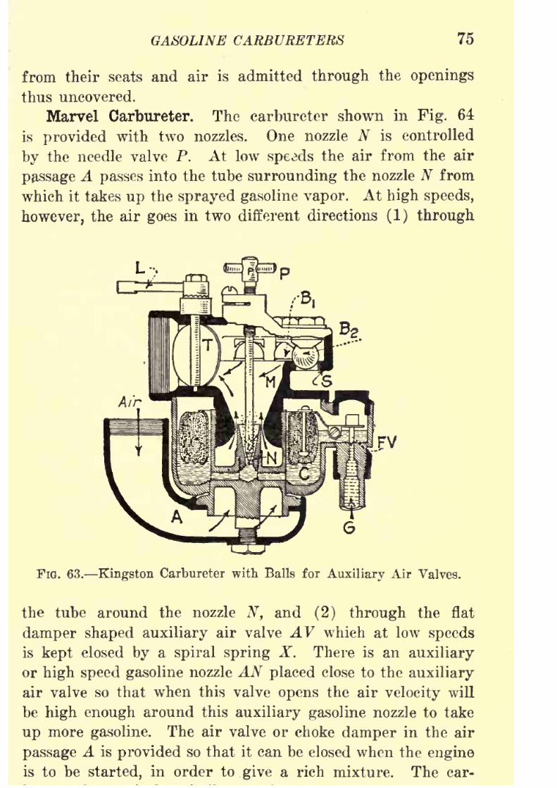
8/9/2019 (1921) Gasoline Automobiles
http://slidepdf.com/reader/full/1921-gasoline-automobiles 87/280
GASOLINE CARBURETERS 75
from their seats and air is admitted through the openings
thus uncovered.
MarvelCarbureter. The carbureter shown in
Fig.64
is provided with two nozzles. One nozzle N is controlled
by the needle valve P. At low speeds the air from the air
passage A passes into the tube surrounding the nozzle N from
which it takes up the sprayed gasoline vapor. At high speeds,
however, the air goes in two different directions (1) through
L-,
FIG. 63. Kingston Carbureter with Balls for Auxiliary Air Valves.
the tube around the nozzle N, and (2) through the flat
damper shaped auxiliary air valve AV which at low speeds
is kept closed by a spiral spring X. There is an auxiliary
or high speed gasoline nozzle AN placed close to the auxiliary
air valve so that when this valve opens the air velocity will
be high enough around this auxiliary gasoline nozzle to take
up more gasoline. The air valve or choke damper in the air
passage A is provided so that it can be closed when the engineis to be started, in order to give a rich mixture. The car-

8/9/2019 (1921) Gasoline Automobiles
http://slidepdf.com/reader/full/1921-gasoline-automobiles 88/280
76 GASOLINE AUTOMOBILES
cylinders in which hot exhaust gas from the engine exhaust
pipe circulates. A damper in the pipe carrying the exhaust
gas to the jacket when opened, allows some of the hot exhaustgas from the engine exhaust pipe to flow through cored pas-
sages E shown in the figure. The heat from the hot gas
is for making vaporization in the carbureter more rapid in
cold weather. The damper regulating the flow of this hot
FV-Air
FlG. 64. Marvel Carbureter.
exhaust gas is controlled automatically by the lever L on the
throttle valve T in such a way that when the throttle valve
is opened half way or more the exhaust gas damper is closed.
"Plain Tube" Carbureter. Fig. 65 shows the parts of
a very common type of carbureter. The gasoline from the
float chamber is regulated in its flow by the high speed
adjustment needle 1 from which the gasoline flows into the
pool below the valve 3 or into the long "idling" tube con-
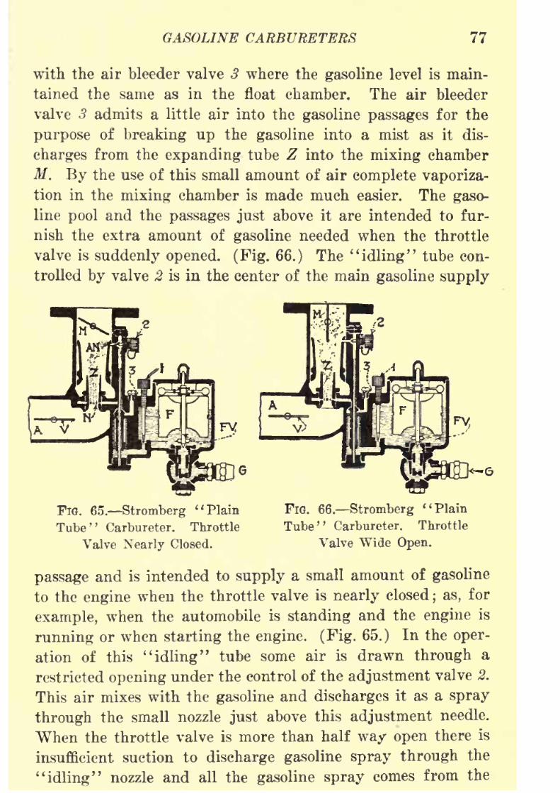
8/9/2019 (1921) Gasoline Automobiles
http://slidepdf.com/reader/full/1921-gasoline-automobiles 89/280
GASOLINE CARBURETERS 77
with the air bleeder valve 3 where the gasoline level is main-
tained the same as in the float chamber. The air bleeder
valve 3 admits a little air into the gasoline passages for the
purpose of breaking up the gasoline into a mist as it dis-
charges from the expanding tube Z into the mixing chamber
M. By the use of this small amount of air complete vaporiza-
tion in the mixing chamber is made much easier. The gaso-
line pool and the passages just above it are intended to fur-
nish the extra amount of gasoline needed when the throttle
valve is suddenly opened. (Fig. 66.) The "idling" tube con-
trolled by valve 2 is in the center of the main gasoline supply
FlG. 65. Stromberg "Plain
Tube ' '
Carbureter. Throttle
Valve Nearly Closed.
FlG. 66. Stromberg "Plain
Tube" Carbureter. Throttle
Valve Wide Open.
passage and is intended to supply a small amount of gasoline
to the engine when the throttle valve is nearly closed; as, for
example, when the automobile is standing and the engine is
running or when starting the engine. (Fig. 65.) In the oper-
ation of this "idling" tube some air is drawn through a
restricted opening under the control of the adjustment valve 2.
This air mixes with the gasoline and discharges it as a spray
through the small nozzle just above this adjustment needle.
When the throttle valve is more than half way open there is
insufficient suction to discharge gasoline spray through the
"idling" nozzle and all the gasoline spray comes from the

8/9/2019 (1921) Gasoline Automobiles
http://slidepdf.com/reader/full/1921-gasoline-automobiles 90/280
78 GASOLINE AUTOMOBILES
A detail showing the operation of the air bleeder valve 3,
and of the small gasoline tubes discharging into the expand-
ingnozzle Z is shown in
Fig.67.
Fie. 67. Stromberg Air Bleeder Valve.
A somewhat simpler type of the same make of carbureter
is shown in Fig. 68 which has two nozzles for the gasoline
Air
FIG. 68. Stromberg Double Nozzle Carbureter.
supply. At low speed the nozzle N discharges gasoline vaporinto the expanding tube. At high speed the additional air

8/9/2019 (1921) Gasoline Automobiles
http://slidepdf.com/reader/full/1921-gasoline-automobiles 91/280
GASOLINE CARBURETERS 79
which regulates also automatically a gasoline supply through
the auxiliary nozzle AN. This gasoline discharges in the
direction of the air flowing through the auxiliary air valve
AV. By this method there is an extra supply of gasoline for
high speed and for heavy pulling. This carbureter has an air
valve or choke damper V in the air inlet for starting the
engine in cold weather. There is a connection from this choke
air valve to the auxiliary air valve AV, so that closing the
choke valve closes tightly the auxiliary valve.
The choke air valve is controlled either from the dash or
from the steering column, depending on the method of in-
stallation.
Stewart Carbureter. The unique feature of the car-
bureter shown in Fig. 69 is that it has a relatively heavy
air valve W surrounding the spray nozzle N. This cap-
like air valve W rests on its seat S and shuts off any air
flowing from the air chamber marked "Air." As soon as
the engine starts, vacuum is formed in the mixing chamber
M and the valve W is lifted from its seat in proportion to the
amount of the engine suction. At the same time because of
this suction, the gasoline will be sucked up through the spray
nozzle N. The lower end of the air valve W extends down
and is surrounded by the gasoline in the extension of the float
chamber, and the extreme lower end has a needle valve (some-
times called a metering pin) P for a central guide. The
needle valve extends upward into the central tube in the
valve W, so that as the suction varies, the position of the
air valve W will move up and down to regulate the flow
of air by the distance it rises above the seat 8, and, the
amount of gasoline by the distance the central tube in the
valve is above the metering pin P. This device is intended
to regulate the volume of air and the amount of gasoline
going into the mixing chamber so as to increase or decrease
the amount of each in the same proportion. Most of the air
going through the carbureter passes through the space be-
tween the air valve and its seat 8, but the small amount of
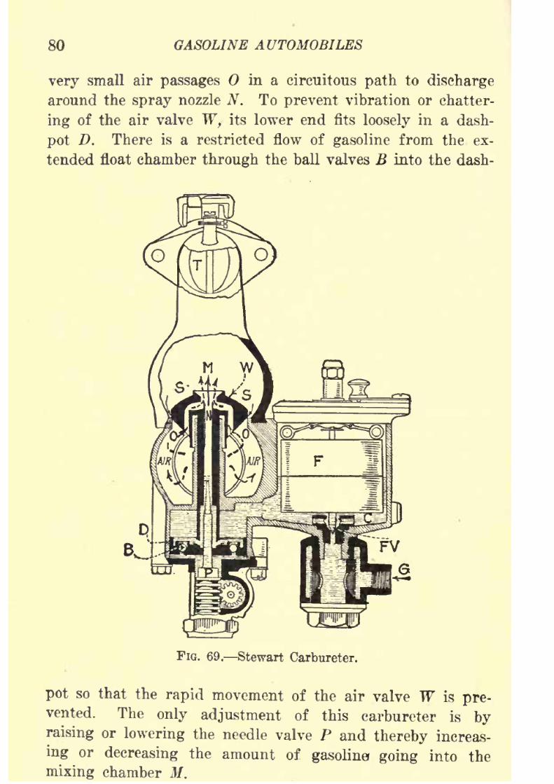
8/9/2019 (1921) Gasoline Automobiles
http://slidepdf.com/reader/full/1921-gasoline-automobiles 92/280
80 GASOLINE AUTOMOBILES
very small air passages in a circuitous path to discharge
around the spray nozzle N. To prevent vibration or chatter-
ing of the air valve W,- its lower end fits loosely in a dash-
pot D. There is a restricted flow of gasoline from the ex-
tended float chamber through the ball valves B into the dash-
FIG. 69. Stewart Carbureter.
pot so that the rapid movement of the air valve W is pre-vented. The only adjustment of this carbureter is by
raising or lowering the needle valve P and thereby increas-
ing or decreasing the amount of gasoline going into the
mixing chamber M.
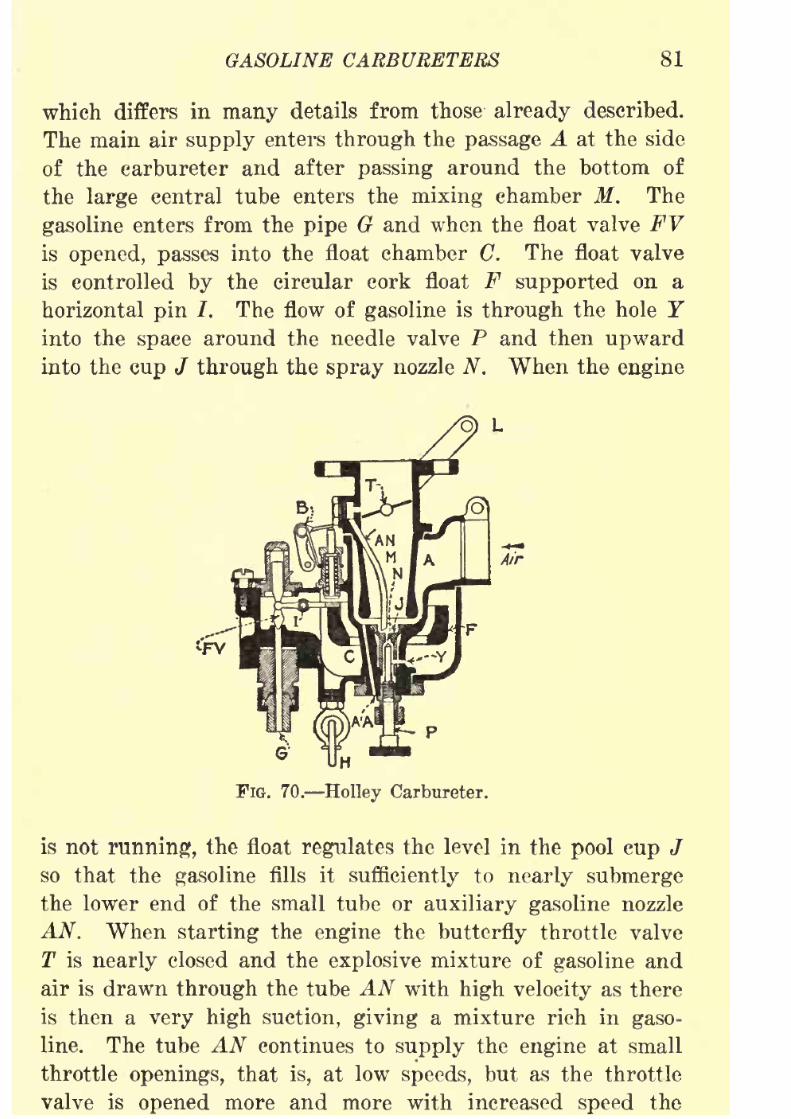
8/9/2019 (1921) Gasoline Automobiles
http://slidepdf.com/reader/full/1921-gasoline-automobiles 93/280
GASOLINE CARBURETERS 81
which differs in many details from those already described.
The main air supply enters through the passage A at the side
of the carbureter and after passing around the bottom ofthe large central tube enters the mixing chamber M. The
gasoline enters from the pipe G and when the float valve FVis opened, passes into the float chamber C. The float valve
is controlled by the circular cork float F supported on a
horizontal pin /. The flow of gasoline is through the hole Yinto the space around the needle valve P and then upward
into the cup J through the spray nozzle N. When the engine
G
FIG. 70. Holley Carbureter.
is not running, the float regulates the level in the pool cup J
so that the gasoline fills it sufficiently to nearly submerge
the lower end of the small tube or auxiliary gasoline nozzle
AN. When starting the engine the butterfly throttle valve
T is nearly closed and the explosive mixture of gasoline and
air is drawn through the tube AN with high velocity as there
is then a very high suction, giving a mixture rich in gaso-
line. The tube AN continues to supply the engine at small
throttle openings, that is, at low speeds, but as the throttle
valve is opened more and more with increased speed the

8/9/2019 (1921) Gasoline Automobiles
http://slidepdf.com/reader/full/1921-gasoline-automobiles 94/280
82 GASOLINE AUTOMOBILES
ate and high speeds all the mixture is supplied through the
main mixing tube M. A slight modification is shown in
Fig. 71 which is intended for attachment to a horizontalintake pipe of an engine. In this case the auxiliary tube
AN is bent so as to be horizontal and discharges close to the
throttle valve T. Some carbureters of this type have an
auxiliary air passage AA (Fig. 70) which is always open.
It gives a very direct flow of air for starting.
The Schebler Model L Carbureter as shown in Fig. 72
has a device for regulating the nozzle opening by means of
the needle valve or metering pin P which is operated auto-
Air
FIG. 71. Holley Carbureter for Horizontal Intake Pipe.
matically with the movement of the butterfly throttle valve T.
The flow of gasoline through the nozzle can be adjusted in
this type of carbureter for an intermediate speed in addition
to the usual low and high speed adjustments as in most other
types. Each of these three adjustments is independent of
the others. The opening of the butterfly throttle valve Tfor high speed or a heavy pull raises the metering pin (needle
valve) P and increases the supply of gasoline. The auxiliary
air valve AV is shown at the left-hand side of the figure.
A priming pin and lever are shown just above the cork float
F. By pressing on this pin the level of gasoline in the float
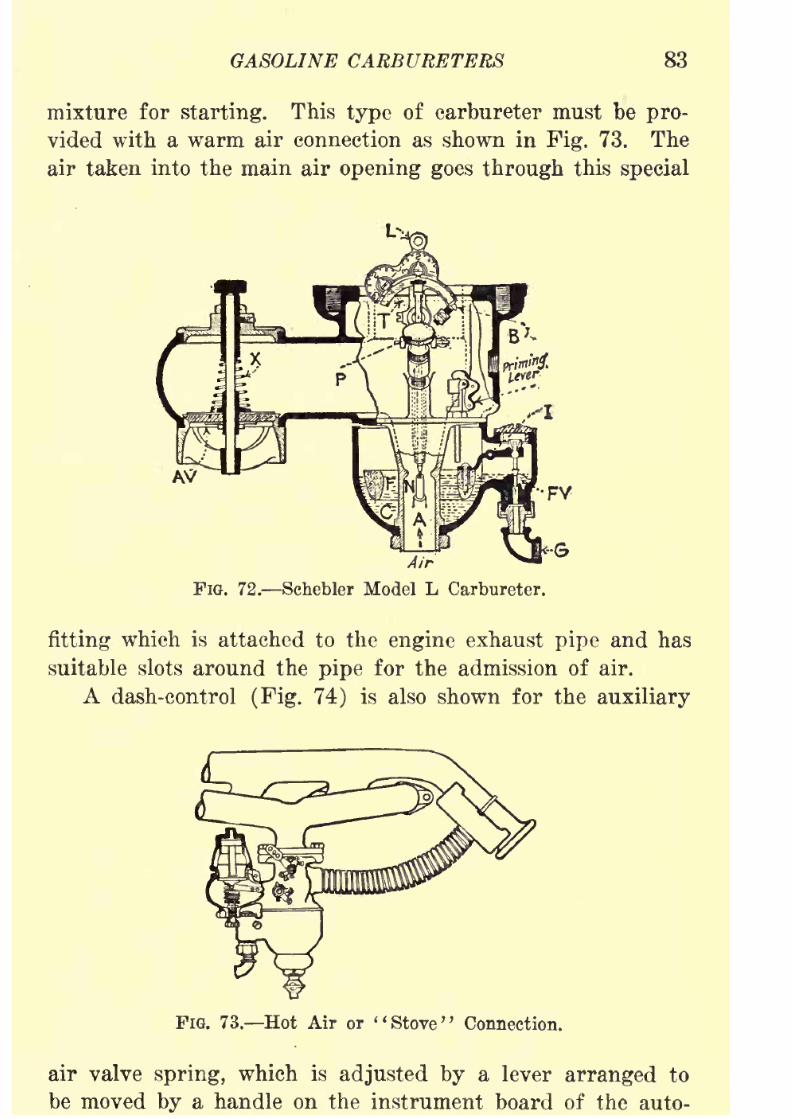
8/9/2019 (1921) Gasoline Automobiles
http://slidepdf.com/reader/full/1921-gasoline-automobiles 95/280
GASOLINE CARBURETERS 83
mixture for starting. This type of carbureter must be pro-
vided with a warm air connection as shown in Fig. 73. The
air taken into the main air opening goes through this special
Air
FIG. 72. Schebler Model L Carbureter.
fitting which is attached to the engine exhaust pipe and has
suitable slots around the pipe for the admission of air.
A dash-control (Fig. 74) is also shown for the auxiliary
FiG. 73. Hot Air or "Stove" Connection.
air valve spring, which is adjusted by a lever arranged to
be moved by a handle on the instrument board of the auto-
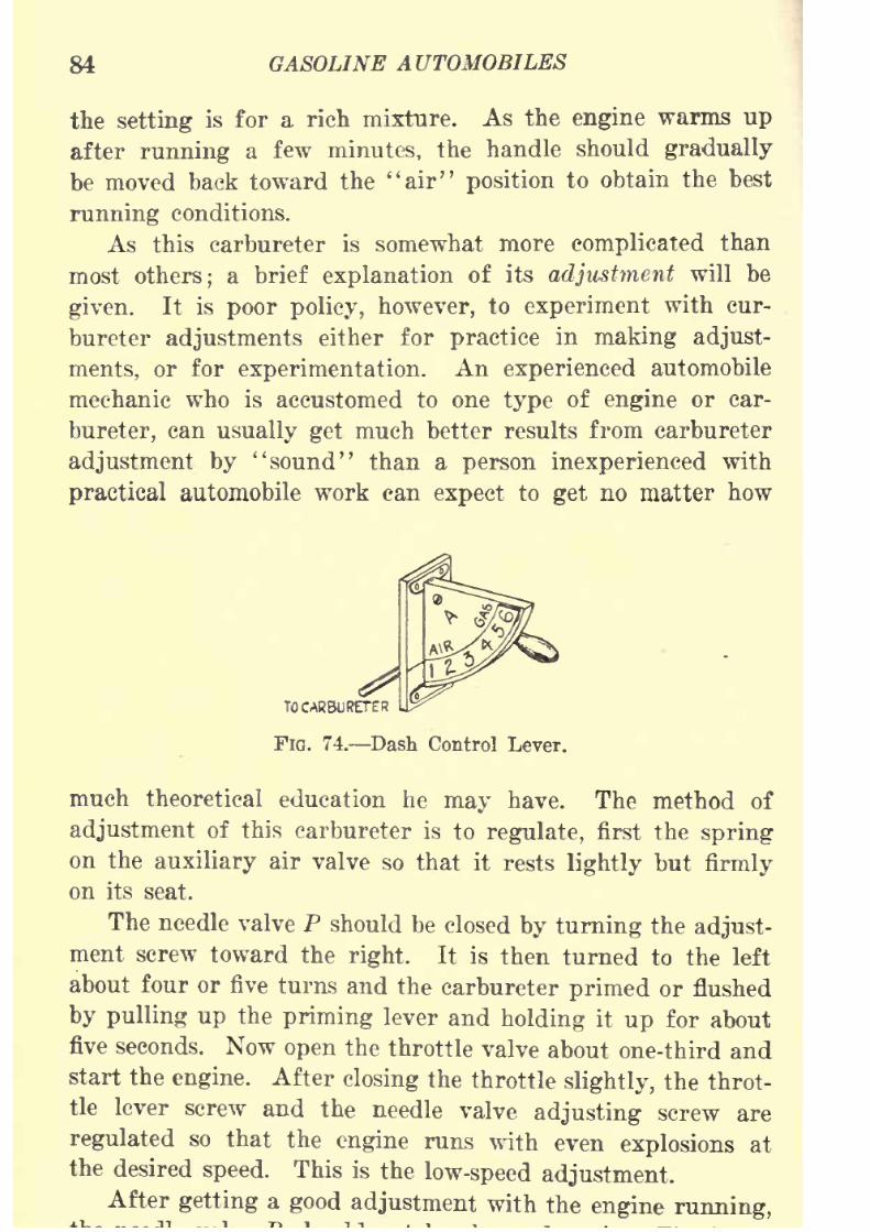
8/9/2019 (1921) Gasoline Automobiles
http://slidepdf.com/reader/full/1921-gasoline-automobiles 96/280
84 GASOLINE AUTOMOBILES
the setting is for a rich mixture. As the engine warms up
after running a few minutes, the handle should gradually
bemoved
back toward the "air"position
to obtain the best
running conditions.
As this carbureter is somewhat more complicated than
most others; a brief explanation of its adjustment will be
given. It is poor policy, however, to experiment with cur-
bureter adjustments either for practice in making adjust-
ments, or for experimentation. An experienced automobile
mechanic who is accustomed to one type of engine or car-
bureter, can usually get much better results from carbureter
adjustment by "sound" than a person inexperienced with
practical automobile work can expect to get no matter how
TO CARBURETER
FIG. 74. Dash Control Lever.
much theoretical education he may have. The method of
adjustment of this carbureter is to regulate, first the spring
on the auxiliary air valve so that it rests lightly but firmly
on its seat.
The needle valve P should be closed by turning the adjust-
ment screw toward the right. It is then turned to the left
about four or five turns and the carbureter primed or flushed
by pulling up the priming lever and holding it up for about
five seconds. Now open the throttle valve about one-third and
start the engine. After closing the throttle slightly, the throt-
tle lever screw and the needle valve adjusting screw are
regulated so that the engine runs with even explosions at
the desiredspeed.
This is thelow-speed adjustment.
After getting a good adjustment with the engine running,

8/9/2019 (1921) Gasoline Automobiles
http://slidepdf.com/reader/full/1921-gasoline-automobiles 97/280
GASOLINE CARBURETERS 85
mediate and high-speed adjustments are made on the dials.
The pointer on the right or intermediate speed dial should
be set halfway between figures 1 and 3. The spark ignition
should be set for moderate speed and the throttle opened so
that the roller on the track running below the dials is in
line with the first dial. If the engine back-fires, with the
throttle in this position, the indicator or pointer should be
turned a little more toward figure 3;
if the mixture is too
rich,the indicator should be turned back, or toward figure 1,
until the engine is running properly with the throttle in
intermediate speed position. For high-speed adjustment the
throttle is opened wide and the adjustment made for high
speed on the second dial in the same manner as the adjust-
ment for intermediate speed on the first dial.
Rayfield Model G Carbureter. A somewhat complicated
carbureter illustrated in Fig. 75 has two gasoline nozzles
and two air inlets, both of which are used for the admission
of auxiliary air. There are no air valve adjustments but two
gasoline adjustments, one for low speed and the other for
high speed. For low-speed operation air is taken into the
mixing chamber through the main or "constant" opening
A. In the mixing chamber M this air mixes with the gaso-
line vapor which the engine suction draws from the nozzle
below the valve Pj. When the speed increases, the engine suc-
tion opens the upper automatic (auxiliary) air valve AVand increases the amount of air. In the automatic movement
of this air valve it presses down on the metering pin P 2 just
below so that at the same time additional"gasoline
comes
through this auxiliary nozzle. A second auxiliary air valve
at the bottom of the carbureter opens and closes with the
main or upper automatic air valve AV as they are con-
nected together by levers and links. The effect of the
lower auxiliary air valve is to give a still greater volume
of air at high engine speeds. The upper automatic air valve
is controlled by the tension of a spiral spring shown directly
it in A

8/9/2019 (1921) Gasoline Automobiles
http://slidepdf.com/reader/full/1921-gasoline-automobiles 98/280
86 GASOLINE AUTOMOBILES
dashpot is provided for the purpose of preventing vibration
of the valve and has also the effect of forcing out the gasoline
from the auxiliary valve P2 when
the throttle valve is sud-
denly opened, and a quick response of the engine is desired
in the amount of power to be delivered.
This carbureter is heated by the circulation through its
jacket of ~kot water which is taken from a pipe attached
to the upper part of the water jacket on the engine where
the temperature of the engine cooling water is highest. This
water is discharged from the carbureter jacket through a pipe
AV
-M/r
FIG. 75. Eayfield Carbureter.
connected usually to the suction side of the cooling water
pump. These pipe connections provide a constant circulation
of hot water through the jackets of the carbureter. The main
or ''constant" air opening A is connected by a piece of
flexible tubing to the usual attachment (Fig. 73) on the ex-
haust pipe for heating the air. A dash-control wire is con-
nected to the valve Plin such a way that its movement opens
or closes the main gasoline nozzle.
The vertical tube at the left of the mixing chamber Mdischarges a rich mixture of gasoline vapor and air above

8/9/2019 (1921) Gasoline Automobiles
http://slidepdf.com/reader/full/1921-gasoline-automobiles 99/280
GASOLINE CARBURETERS 87
Compound Nozzle Carbureter. In another type of car-
bureter the gasoline is supplied from a Compound nozzle
which has actually two nozzles, one inside the other as
illustrated in Figs. 76 and 77. It will be noted that when
the throttle valve is closed (Fig. 76) the outside nozzle is
supplied by a gravity flow by the constant level maintained
in the auxiliary fuel well W. This compound nozzle is satis-
factory for giving a uniform explosive mixture of gasoline
and air for varying suction in the engine cylinders. Other
carbureters have been made to use practically the same prin-
ciple by combining the two nozzles of this compound type
in a single one, and have provision for suitable air bleeds
FIG. 76.
CompoundNozzle
(Throttle Valve Closed).
FIG. 77.
Compound Nozzle(Throttle Valve Open).
(Fig. 67) so that the amount of gasoline will be more and
more weakened by excess air as the suction increases.
Zenith Carbureter. The carbureter shown in Fig. 78
differs from most of the carbureters which ^have been ex-
plained in that it has no auxiliary air valve. It has a com-
pound nozzle (Figs. 77 and 78) consisting of an inner nozzle
for which the gasoline is supplied direct from the float chamber
C, and an outer nozzle for the purpose of reducing the strength
of the mixture at high speeds. This provision as to the
gasoline supply is possible because the amount of gasoline
passing throughthe outside or
compensatingnozzle is constant
at all speeds. When the speed of the engine increases the
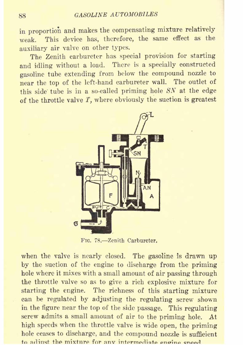
8/9/2019 (1921) Gasoline Automobiles
http://slidepdf.com/reader/full/1921-gasoline-automobiles 100/280
88 GASOLINE AUTOMOBILES
in proportion and makes the compensating mixture relatively
weak. This device has, therefore, the same effect as the
auxiliary air valve on other types.
The Zenith carbureter has special provision for starting
and idling without a load. There is a specially constructed
gasoline tube extending from below the compound nozzle to
near the top of the left-hand carbureter wall. The outlet of
this side' tube is in a so-called priming hole SN at the edge
of the throttle valve T, where obviously the suction is greatest
FIG. 78. Zenith Carbureter.
when the valve is nearly closed. The gasoline is drawn up
by the suction of the engine to discharge from the priming
hole where it mixes with a small amount of air passing throughthe throttle valve so as to give a rich explosive mixture for
starting the engine. The richness of this starting mixture
can be regulated by adjusting the regulating screw shown
in the figure near the top of the side passage. This regulating
screw admits a small amount of air to the priming hole. At
high speeds when the throttle valve is wide open, the priming
hole ceases to discharge, and the compound nozzle is sufficient
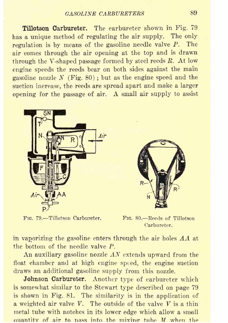
8/9/2019 (1921) Gasoline Automobiles
http://slidepdf.com/reader/full/1921-gasoline-automobiles 101/280
GASOLINE CARBURETERS 89
Tillotson Carbureter. The carbureter shown in Fig. 79
has a unique method of regulating the air supply. The only
regulation is by means of the gasoline needle valve P. The
air comes through the air opening at the top and is drawn
through the V-shaped passage formed by steel reeds R. At low
engine speeds the reeds bear on both sides against the main
gasoline nozzle N (Fig. 80) ;but as the engine speed and the
suction increase, the reeds are spread apart and make a larger
opening for the passage of air. A small air supply to assist
. Tillotson Carbureter. FIG. 80. Eeeds of Tillotson
Carbureter.
in vaporizing the gasoline enters through the air holes AA at
the bottom of the needle valve P.
Anauxiliary gasoline
nozzle AN extends
upwardfrom the
float chamber and at high engine speed, the engine suction
draws an additional gasoline supply from this nozzle.
Johnson Carbureter. Another type of carbureter which
is somewhat similar to the Stewart type described on page 79
is shown in Fig. 81. The similarity is in the application of
a weighted air valve V. The outside of the valve V is a thin
metal tube with notches in its lower edge which allow a smell
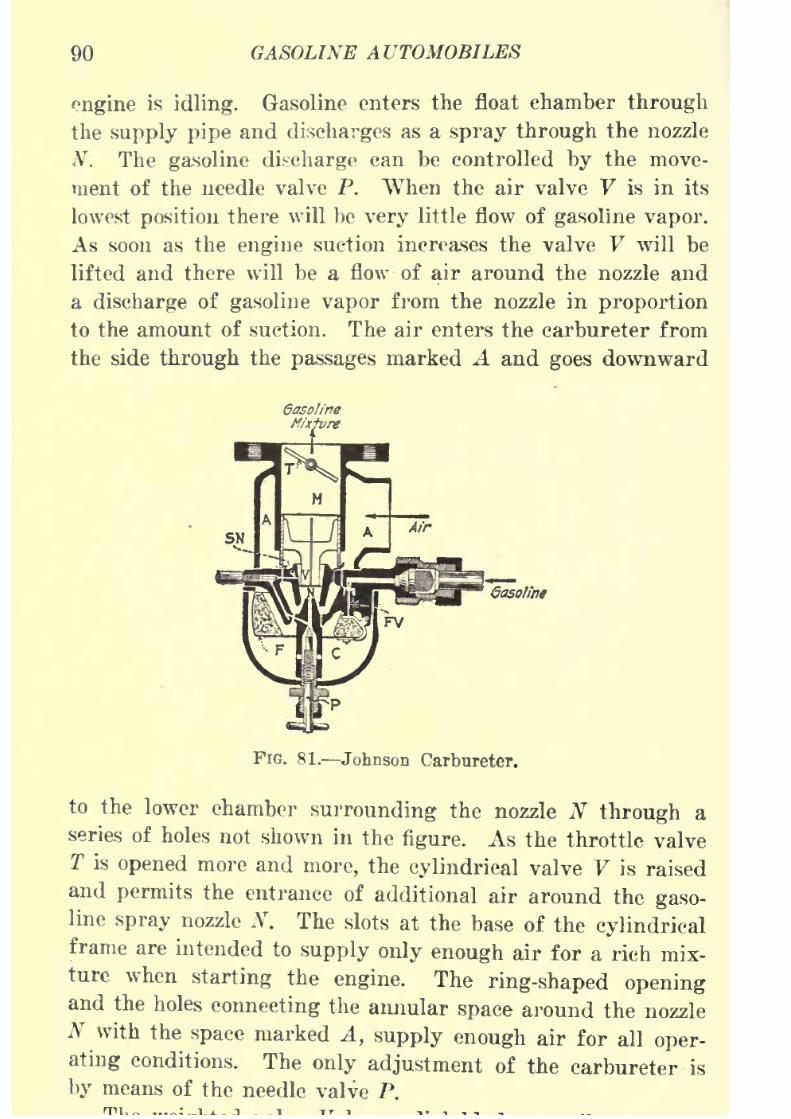
8/9/2019 (1921) Gasoline Automobiles
http://slidepdf.com/reader/full/1921-gasoline-automobiles 102/280
90 GASOLINE AUTOMOBILES
engine is idling. Gasoline enters the float chamber through
the supply pipe and discharges as a spray through the nozzle
N. The gasoline discharge can be controlled by the move-
ment of the needle valve P. When the air valve V is in its
lowest position there will be very little flow of gasoline vapor.
As soon as the engine suction increases the valve V will be
lifted and there will be a flow -of air around the nozzle and
a discharge of gasoline vapor from the nozzle in proportion
to the amount of suction. The air enters the carbureter from
the side through the passages marked A and goes downward
6aso!ine
FIG. 81. Johnson Carbureter.
to the lower chamber surrounding the nozzle N through a
series of holes not shown in the figure. As the throttle valve
T is opened more and more, the cylindrical valve V is raised
and permits the entrance of additional air around the gaso-line spray nozzle N. The slots at the base of the cylindrical
frame are intended to supply only enough air for a rich mix-
ture when starting the engine. The ring-shaped openingand the holes connecting the annular space around the nozzle
N with the space marked A, supply enough air for all oper-
ating conditions. Theonly adjustment of the carbureter is
by means of the needle valve P.
8/9/2019 (1921) Gasoline Automobiles
http://slidepdf.com/reader/full/1921-gasoline-automobiles 103/280
GASOLINE CARBURETERS 91
at one end of its central shaft and at the other to the cylin-
drical frame of the valve. The explosive mixture discharging
againstthe blades of valve V is
givena
rotarymotion
byprojections (not shown in the figure) on the expanding tube
(Venturi) surrounding the lower end of the valve V. This
rotary motion of the mixture, gives also a rotary motion to
the valve. This mixture and the additional air entering
through the ring-shaped opening are mixed by this motion,
with the result that an unusually good mixture is delivered
to the engine. It is difficult to test the rotary operation of
a valve of this kind so as to know whether it is actually
operating as intended. Generally, the operation of such de-
vices is good when new; but usually, after a little time, they
fail to operate.
Schebler Carbureter Model A. Fig. 82 shows a some-
what complicated carbureter of the plain tube type. The air
enters through the main air passage A and passes upward
through a slightly expanding or Venturi tube around a com-
pound spray nozzle 12. The gasoline supply enters at G
through the float valve FV. From the float chamber there
are two paths for the gasoline to discharge. One path is
around the "idling" needle valve 9 and through the pas-sage 7. The other path is around the main gasoline needle
valve 10. When starting the engine, especially in cold weather,
if the choke valve V is closed the air supply will be very much
restricted and there will be a strong suction to draw gasoline
through the irregular passage 7 to discharge through the
auxiliary gasoline nozzle AN, just above the partly closed posi-
tion of the throttle valve T. With the throttle valve in this
position, some gasoline will also be drawn from three holes
marked 13 and the "lip" marked 6. This gives a rich mix-
ture which makes starting easy.
When the engine is running idle and the throttle valve T
is nearly closed there will be only a small amount of air
passing through the expanding tube into the mixing chamberM and its velocity will not be sufficient to draw gasoline
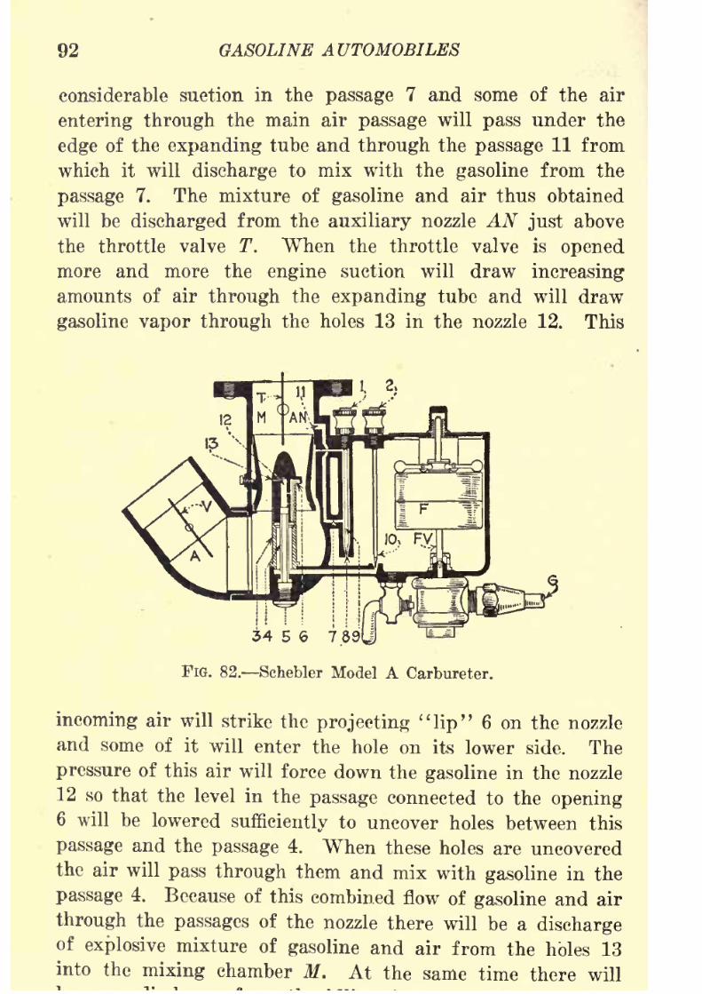
8/9/2019 (1921) Gasoline Automobiles
http://slidepdf.com/reader/full/1921-gasoline-automobiles 104/280
92 GASOLINE AUTOMOBILES
considerable suction in the passage 7 and some of the air
entering through the main air passage will pass under the
edgeof the
expandingtube and
throughthe
passage11 from
which it will discharge to mix with the gasoline from the
passage 7. The mixture of gasoline and air thus obtained
will be discharged from the auxiliary nozzle AN just above
the throttle valve T. When the throttle valve is opened
more and more the engine suction will draw increasing
amounts of air through the expanding tube and will draw
gasoline vapor through the holes 13 in the nozzle 12. This
1.2,
34 5 6 78J
FIG. 82. Schebler Model A Carbureter.
incoming air will strike the projecting "lip" 6 on the nozzle
and some of it will enter the hole on its lower side. The
pressure of this air will force down the gasoline in the nozzle
12 so that the level in the passage connected to the opening6 will be lowered sufficiently to uncover holes between this
passage and the passage 4. When these holes are uncovered
the air will pass through them and mix with gasoline in the
passage 4. Because of this combined flow of gasoline and air
through the passages of the nozzle there will be a dischargeof
explosive mixture of gasoline and air from the holes 13into the mixing chamber M. At the same time there will
8/9/2019 (1921) Gasoline Automobiles
http://slidepdf.com/reader/full/1921-gasoline-automobiles 105/280
GASOLINE CARBURETERS 93
nozzle AN until the throttle valve is about half way opened ;
but when wide open the flow through AN ceases. When the
throttle valve T is wideopen,
as it would be forhigh engine
speed, there is unrestricted flow of air through the expanding
tube and also a maximum amount of suction at the holes 13
in the nozzle. This large flow of air exerts increased pressure
on the "lip" 6 causing the air to enter still farther into the
passage connected to the opening under the "lip" and lowers
the gasoline level by the same amount that the air enters.
This permits more air to be drawn through the connecting
holes between this passage and the passage 4. Thus the
proportion of air and gasoline delivered to the mixing cham-
ber M is kept constant because of the varying amount of gaso-
line discharged from the holes 13.
After starting and warming up the engine, it is neces-
sary to close the choke air valve V until the parts of the
engine are sufficiently heated to give good air temperature.
An engine equipped with this carbureter will start readily
with the choke air valve closed one-half to three-quarters of
the way. When the weather is very cold it is sometimes
necessary to close this valve entirely, but this should be done
onlyfor
an instant asit
cutsoff
practicallyall the
air anddelivers a mixture much too rich in gasoline for operating
the engine.
Cadillac Carbureter. Several novel features are found
on the Cadillac carbureter, Fig. 83. The gasoline supply is
through a nozzle N placed at the throat of an expanding or
so-called Venturi tube Z. The main or primary air supply
is taken in through an opening on the side of the carbureter
as shown. The auxiliary air valve AV is a shutter type which
has a counter weight. This valve is controlled by a coil
spring X.
A throttle pump shown in the figure is regulated by
the movement of the throttle valve T. Its purpose is to
force gasoline through the spray nozzle N when the throttle
is opened suddenly and the engine speed is to be increased

8/9/2019 (1921) Gasoline Automobiles
http://slidepdf.com/reader/full/1921-gasoline-automobiles 106/280
94 GASOLINE AUTOMOBILES
pump has little or no effect upon the flow of the gasoline
through the spray nozzle.
Packard Carbureter. This carbureter as shown at theleft-hand side of Fig. 85, page 99, is of the usual auxiliary
air valve type. The main air supply at the left of the *arbu-
reter furnishes all the air at low speeds. This air current
picks up the gasoline from the stand pipe nozzle N. "When
the engine speed and the suction are increased, the auxiliary
air valve opens and supplies the additional air needed. The
opening and closing of this valve are regulated by the ten-
CaM.BffSi'n,
DrainPfpe]
FIG. 83. Cadillac Carbureter.
sion on its two springs, one inside the other. This tension
is adjusted by two cams under the springs. Connections to
these cams are made to the control board on the dash so
that the adjustment can be made from the driver's seat.
This is the only adjustment to be made. It will be noticed
that the carbureters used on the Packard and Cadillac auto-
mobiles are relatively simple in the arrangements for adjust-
ment.
Intake Manifolds. The best practice is to place the car-bureter close to the engine cylinders so that the heat from
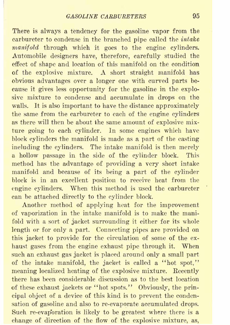
8/9/2019 (1921) Gasoline Automobiles
http://slidepdf.com/reader/full/1921-gasoline-automobiles 107/280
GASOLINE CARBURETERS 95
There is always a tendency for the gasoline vapor from the
carbureter to condense in the branched pipe called the intake
manifold throughwhich it
goesto the
engine cylinders.Automobile designers have, therefore, carefully studied the
effect of shape and location of this manifold on the condition
of the explosive mixture. A short straight manifold has
obvious advantages over a longer one with curved parts be-
cause it gives less opportunity for the gasoline in the explo-
sive mixture to condense and accumulate in drops on the
walls. It is also important to have the distance approximately
the same from the carbureter to each of the engine cylinders
as there will then be about the same amount of explosive mix-
ture going to each cylinder. In some engines which have
block cylinders the manifold is made as a part of the casting
including the cylinders. The intake manifold is then merely
a hollow passage in the side of the cylinder block. This
method has the advantage of providing a very short intake
manifold and because of its being a part of the cylinder
block is in an excellent position to receive heat from the
engine cylinders. When this method is used the carbureter
can be attached directly to the cylinder block.
Another method of applying heat for the improvementof vaporization in the intake manifold is to make the mani-
fold with a sort of jacket surrounding it either for its whole
length or for only a part. Connecting pipes are provided on
this jacket to provide for the circulation of some of the ex-
haust gases from the engine exhaust pipe through it. When
such an exhaust gas jacket is placed around only a small part
of the intake manifold, the jacket is called a ''hot spot,"
meaning localized heating of the explosive mixture. Recently
there has been considerable discussion as to the best location
of these exhaust jackets or "hot spots." Obviously, the prin-
cipal object of a device of this kind is to prevent the conden-
sation of gasoline and also to re-evaporate accumulated drops.
Such re-evap*oration is likely to be greatest where there is a
change of direction of the flow of the explosive mixture, as,
8/9/2019 (1921) Gasoline Automobiles
http://slidepdf.com/reader/full/1921-gasoline-automobiles 108/280
96 GASOLINE AUTOMOBILES
manifold and the stream divides to flow to the branches.
Fig. 84 shows one method of applying an exhaust jacket
where the carbureter pipe enters the manifold. In some other
designs, the exhaust jacket is made large enough to surround
the pipe from the carbureter and also the manifold itself
for a short distance from the place where it branches. It is
claimed, however, that practically all the condensation, at
least of that part which accumulates in drops, is on the wall
of the manifold directly opposite the opening of the pipe
from the carbureter into the intake manifold. It is for this
reason that it is claimed the device shown in Fig. 84 is more
Exhaust Manifofcl
ThroWe
FIG. 84. Hot-spot Manifold.
effective in general service than devices covering a greaterportion of the manifold with an exhaust jacket. For verygood reasons, the best method of preventing gasoline accu-
mulation in drops in the intake manifold is by heating it onits bottom side by the exhaust pipe placed closely ~below theintake manifold. There is, of course, always the disadvantagethat if there is too much heated surface without regula-tion, the temperature of the explosive mixture may be-
come much too high in warm weather for efficient engine
operation.Hot-air Attachment. Except in very hot weather the
8/9/2019 (1921) Gasoline Automobiles
http://slidepdf.com/reader/full/1921-gasoline-automobiles 109/280
GASOLINE CARBURETERS 97
air as it improves vaporization of gasoline. A great many
carbureters are provided with an attachment for heat-
ingthe air which
goesinto the air intake of the car-
bureter. This is usually done by taking it through a
pipe attachment which takes to the carbureter, air which
has been heated by contact with the hot exhaust pipe
of the engine. Fig. 73 shows an attachment of this
kind.
Hot-water Attachment. For the same reason that hot-
air attachments are used on carbureters, some carbureters
are provided with a water jacket as shown on the Rayfield
carbureter in Fig. 75. Hot water from the supply used to
cool the cylinders of the engine is passed through this jacket
which warms the air before and as it passes the carbureter
nozzle.
Disadvantages of Hot-air and Hot-water CarbureterAttachments. In order to avoid the difficulties arising from
the presence of unburned gasoline in the cylinder, provision
must be made for supplying it to the engine cylinders in 'a
dry or completely vaporized condition. The simplest method
of obtaining complete vaporization is by making provision
forheating
the carbureter either
by usingthe hot water
from the engine water jacket or hot gases from the engine
exhaust pipe. Neither of these methods is, however, alto-
gether satisfactory because there is difficulty in regulating
the amount of heat to the requirements. When the engine
is operating with a wide open throttle valve for the condi-
tions of either high speed or heavy load, either of these
methods will give a great deal too much heat to the car-
bureter if the amount is adjusted to give the right amount
for light load operation. There are two objectionable fea-
tures of this kind of carbureter heating when the throttle
valve is more than half way open: (1) the added heat
increases the volume of the explosive mixture and conse-
quently reduces the weight of explosive mixture used to
such an extent that the speed of the engine is appreciably
8/9/2019 (1921) Gasoline Automobiles
http://slidepdf.com/reader/full/1921-gasoline-automobiles 110/280
98 GASOLINE AUTOMOBILES
ture of the explosive mixture so high that with the further
addition of heat during the compression stroke in the en-
gine,and
duringthe
explosion
that follows, the lighter
petroleum fuels like gasoline will be broken up or "dis-
sociated" into gases having hydrogen as the important con-
stituent. This hydrogen when undergoing rapid combustion
because of its high heat content develops a great amount
of energy which is suddenly applied to the top of the engine
piston and produces in the engine what we call "knocking."
There is another reason why the adding of heat to the
carbureter is objectionable when the throttle valve is more
than half-way open, and more especially when wide open.
Wide open throttle valve permits the maximum amount of
explosive mixture to enter the engine cylinders while a
partially opened throttle reduces the amount of mixture
going to the cylinder. It is obvious, therefore, that withwide open throttle with its large amount of explosion mix-
ture, the compression in the cylinders will be carried to a
higher pressure, and consequently the temperature will be
higher than for a partly opened throttle valve. The ideal
arrangement is, obviously, to supply only enough heat to a
carbureter when the throttle valve is partlyopened
to
pro-duce a thoroughly vaporized explosive mixture with arrange-
ments for reducing the amount of heat supplied to the car-
bureter when the throttle valve is wide open.
Packard Fuelizer. Fig. 85 shows in considerable detail
the type of apparatus called the Packard fuelizer whichhas been developed to produce complete vaporization of the
explosive mixture before it gets to the engine cylinder andhas a device for cutting off the supply of heat in proportionto the amount of opening of the engine throttle valve. The
principle of this device is to take advantage of the different
pressures on the two sides of the butterfly throttle valvein the carbureter and cause a small amount of explosivemixture to
go through an auxiliary passage which is parallelto the main intake passage. The amount of mixture going
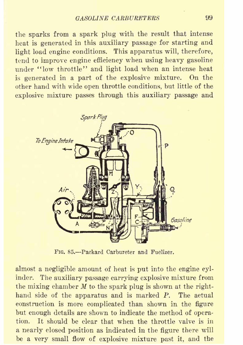
8/9/2019 (1921) Gasoline Automobiles
http://slidepdf.com/reader/full/1921-gasoline-automobiles 111/280
GASOLINE CARBURETERS 99
the sparks from a spark plug with the result that intense
heat is generated in this auxiliary passage for starting and
light load engine conditions. This apparatus will, therefore,tend to improve engine efficiency when using heavy gasoline
under ''low throttle" and light load when an intense heat
is generated in a part of the explosive mixture. On the
other hand with wide open throttle conditions, but little of the
explosive mixture passes through this auxiliary passage and
SparkPlug
ToEngineIrrhke
Gasoline
FIG. 85. Packard Carbureter and Fuelizer.
almost a negligible amount of heat is put into the engine cyl-
inder. The auxiliary passage carrying explosive mixture from
the mixing chamber M to the spark plug is shown at the right-
hand side of the apparatus and is marked P. The actual
construction is more complicated than shown in the figure
but enough details are shown to indicate the method of opera-
tion. It should be clear that when the throttle valve is in
a nearly closed position as indicated in the figure there will
be a very small flow of explosive mixture past it, and the
8/9/2019 (1921) Gasoline Automobiles
http://slidepdf.com/reader/full/1921-gasoline-automobiles 112/280
100 GASOLINE AUTOMOBILES
the auxiliary passage P supplying mixture for combustion
at the spark plug. Opposite the spark plug is the observation
window of heat-resisting glass, which permitsthe action
of the burner to be observed at all times. Instead of actually
taking the explosive mixture into the auxiliary passage P
from the mixing chamber immediately below the throttle valve
the combustible mixture supplied to the auxiliary passage is
made by taking gasoline directly from the carbureter through
the small capillary tube Q and mixing it with air taken
through the pipe Y from the main air passage A. In actual
operation, when the engine is idling, combustion takes place
in the burner silently and continuously and a bluish-green
flame completely fills the combustion chamber. This flame
diminishes in intensity as the throttle is opened, with the
general result that for ordinary driving conditions up to
about twenty-five miles per hour, a mixture temperature
of 150 to 180 degrees Fahrenheit is maintained, giving per-
fect distribution, excellent acceleration, absence of spark-plug
fouling and elimination of dilution of the lubricant in the
crankcase. At higher speeds and wider throttle opening the
influence of the fuelizer gradually decreases until at wide-open
throttle it is
practically out of action, whichis
exactly thecondition desired. This combination has permitted the run-
ning of a twelve-cylinder engine on kerosene at moderate
driving speeds with practically the same results as when
using gasoline, but when using kerosene there are critical tem-
peratures below which we cannot go without considerable
knocking.
Suggestions for Successful Carbureter Operation. It is
obviously impossible to give detailed instructions which will
answer for all types of carbureters, but there are certain
fundamental principles which apply to the adjustment of all
types.
There are numerous troubles coming from an engine
itself or its auxiliaries which must be remedied before anyadjustment on the carbureter can be satisfactorily made.

8/9/2019 (1921) Gasoline Automobiles
http://slidepdf.com/reader/full/1921-gasoline-automobiles 113/280
GASOLINE CARBURETERS 101
the cylinder at the proper time; (2) whether each cylinder
has the proper compression; (3) whether the intake mani-
fold and its connections to the carbureter are free from
air leaks; (4) whether gasoline is being furnished to the
carbureter in sufficient amounts; (5) whether the carbureter
is free from water and dirt in the bottom of the float
chamber.
The engine must be warmed to normal running conditions
before any adjustments are attempted. The engine should
be run idle with the spark retarded and the throttle open only
enough for moderate engine speed. The low-speed adjust-
ment, usually on the gasoline, is made so that the engine
explosions are regular, after which the spark ignition should
be set for high speed and the engine speedd up. Th high-
speed adjustment, usually on the auxiliary air valve, is then
made. When this adjustment is correctly made, the engine
should be first operated slowly and then the throttle valve
should be opened quickly to test the engine for uniformity of
explosions with rapid acceleration. If upon opening the throttle,
the engine back-fires or "spits back," the mixture is weak
and the gasoline adjustment should be made to provide more
fuel. If theengine
is tobe
run atpractically constant
speed there is little need of quick acceleration;the most
economical adjustment will be one which back-fires occa-
sionally on rapid acceleration. "Choking" in the car-
bureter with rapid acceleration indicates too rich a
mixture.
A rich mixture is indicated by the (1) overheating of
the cylinders, (2) waste of fuel, (3) "choking" of the engine,
(4) misfiring at low speeds, (5) heavy black exhaust smoke
with a very disagreeable odor.
A weak mixture manifests itself by (1) back-firing
through the carbureter and (2) by loss of power. Back-
firing or "popping back" through the carbureter is caused
when a fresh charge of explosive mixture enters the cylinder
and comes into contact with a slow-burning charge left in
8/9/2019 (1921) Gasoline Automobiles
http://slidepdf.com/reader/full/1921-gasoline-automobiles 114/280
102 GASOLINE AUTOMOBILES
conditions, since the intake valve is open, the force of the
explosion comes back through the carbureter. A weak mix-
ture bums slowly and is likely to be incompletely burned
when the fresh charge of explosive mixture enters the
cylinder on the next suction stroke. Back-firing may be
caused also by leaky intake valves in the engine cylinder.
Color of Exhaust. A proper mixture will give little or
no smoke at the exhaust. Blue smoke is caused by the
burning of excess lubricating oil and has no relation to the
quality of the mixture. Black smoke is due to the car-
bureter being set for too rich a mixture. White exhaust
in cold weather is due to a small amount of steam in the
exhaust gases and is not objectionable. It is not "smoke."
An easy test to see whether the carbureter is working
right is to run several blocks with the throttle practically
closed, then, when the road is clear, press sharply uponthe accelerator pedal, which opens the throttle wide and
should make the engine speed up and the automobile "jump"forward. If it is sluggish there is too rich a mixture, and if
it sputters and perhaps backfires, it is too weak.
When the engine is running slowly, air passes through
the carbureter so slowly that the gasoline is not broken upinto very fine particles, consequently it does not fully vaporize
and is very easily condensed. It forms liquid gasoline in the
intake pipe or cylinder. This is called "loading up" and is
responsible for black smoke when the automobile is started.
If the owner will make sure that he is not exhausting
black smoke he need not worry about the price of gasoline,
and a little judgment and care will eliminate many of the items
of upkeep expense.
Wherever there is a leak between the carbureter and the
cylinder it lets in air and thins the mixture so that it is
necessary to feed in more gasoline to get a mixture that will
fire and that is wasteful, for a mixture made anywhere else
than in the carbureter is less efficient.
It takes two hundred cubic feet of air to a pint of gasoline
8/9/2019 (1921) Gasoline Automobiles
http://slidepdf.com/reader/full/1921-gasoline-automobiles 115/280
GASOLINE CARBURETERS 103
is usually much more than this to insure carrying off the
unburned nitrogen from the air. For starting and speeding
up, more gasoline is admitted to the vaporizing chamber as
the rich mixture ignites more quickly, but for running, a
leaner mixture produces better results.
The adjustment of the carbureter should not be changed
unless one is certain that it is wrong. If the automobile has
been running with the carbureter working properly and no
one has changed the adjustment, it may safely be assumed, in
most cases, that the carbureter adjustment is correct.
On a dry, warm day the gasoline vaporizes easily and
the maximum charge is readily exploded in the cylinder,
giving maximum power. On a wet cold day one must slightly
decrease the supply of gasoline, or the cylinders will "choke"
and the engine will knock.
When the heavier grades of gasoline as now sold are usedin an automobile engine under normal operating conditions,
when about ninety per cent of the time the engine is
running under a light load, the temperature in the engine
cylinders is not high enough for complete vaporization so
that some of the unburned part is being deposited con-
tinuouslyon the
spark plugsand on the inside of the
cylinderin the form of soot. Soot deposited on the spark plugs
has the effect of short circuiting the parts of the. spark
plugs which should be electrically insulated from each other
and makes them useless for ignition. These soot deposits are
called "carbon."
Some of this unburned portion of the fuel will pass the
piston in the liquid condition into the engine crankcase
where it mixes with the lubricating oil. It is not unusual
to hear of automobile engines which after traveling a few
hundred miles will have in their crankcases a mixture of
gasoline and lubricating oil which gives extremely poor
lubrication, 'so that continued running without its removal
will result in burned out bearings, scored cylinders, andother automobile difficulties arising from improper lubrica-
8/9/2019 (1921) Gasoline Automobiles
http://slidepdf.com/reader/full/1921-gasoline-automobiles 116/280
CHAPTER V
AUTOMOBILE IGNITION
When the explosive mixture of gasoline vapor and air
enters the cylinder of the engine, it must be ignited ; and,
in automobile engines, the usual method of ignition is by
means of an electric spark. Most of the devices for making
and timing the electric spark are complicated. It is neces-
sary, therefore, to know the basic principles because most
of the serious troubles with a modern automobile, excluding
the tires, are with the electrical equipment.If the
"spark"does not come right or does not come at all, there is real
trouble.
Electricity. Very little is known regarding the "sub-
stance" of electricity. In this respect it is almost as much
of a mystery today as when Benjamin Franklin took a spark
from the clouds with his silk kite and string. On the
other hand, the laws of the behavior of electricity under
almost any conditions are well established.
Electrical Pressure or Voltage. Like air, or water, elec-
tricity flows from a position of high pressure to one of low
pressure. There must be pressure for electricity to be car-
ried on wires the same as it is necessary to have pressure
to force water through pipes. Electrical pressure is measuredin units called volts. Thus, if at one point the electrical
pressure is ten volts and at another point it is six volts, the
pressure difference between the two points is four volts. Now,if a metal wire is stretched between the two points an electric
current will flow from the point of high to the point of low
voltage. Electricity flows
throughsome
metals, especiallycopper, with very little resistance; while substances like rub-
8/9/2019 (1921) Gasoline Automobiles
http://slidepdf.com/reader/full/1921-gasoline-automobiles 117/280
AUTOMOBILE IGNITION 105
air) offer very high resistance and are called electric
insulators. Most metals offer little resistance to the flow of
electricity. Cotton, silk, or rubber coverings on wiresare
to insulate them from each other and from other electric
conducting materials. Insulating materials are used as cover-
ings for electric wires which are close together to prevent
the current from flowing from one wire to the other, or to
prevent short-circuiting the wires. The insulation on wires
should not rub on other wires or on metal parts of an auto-
mobile, as continued rubbing may wear through the insulation
and cause short-circuiting.
The quantity of electricity passing over a wire is called
the current, and the unit of measurement of this current
is an ampere. In the flow of water the quantity is expressed
in gallons per hour, while in the flow of electricity the
quantity is expressed in amperes per hour or, for short,
ampere-hours. Flowing electric current must always have a
circuit either through wires or through metal parts of an
engine. If the circuit is interrupted or "broken" by a broken
wire or by an open switch, the current cannot go through.
Electric Batteries for automobile ignition are of two
distinct kinds: (1) drycells
or batteries; and (2) storage,batteries.
Dry Cells are sometimes used, especially on small auto-
mobiles, as a source of electric current for ignition.
Although soon worn out in the usual ignition service, they
are relatively cheap and are easily replaced. Fig. 86 shows
a typical dry cell as it appears when cut open through the
middle (in cross section). The outside cylindrical casing
is made of zinc. Inside of this casing is fitted a piece of
absorbent paper saturated with zinc chemicals and plaster
of Paris. In the middle of the cell is a stick of pure carbon.
The space between the absorbent paper and the carbon stick
is filled with powdered carbon and manganese oxide. To
prevent drying out of the saturated paper, the top of the
cell is sealed air-tight with a tar compound. The electric

8/9/2019 (1921) Gasoline Automobiles
http://slidepdf.com/reader/full/1921-gasoline-automobiles 118/280
106 GASOLINE AUTOMOBILES
The maximum possible current on short circuit (as a dealer
tests it) is from twenty to thirty-fire amperes, depending
somewhat on the size of thecell.
Thecarbon terminal is
often marked with the symbol +. The zinc casing must
have on the outside a covering (side and bottom) of in-
sulating material. Heavy paper is a satisfactory material,
if kept dry.
When a dry cell is nearly exhausted its useful service
can usually be extended by making a small hole in the
Zinc Terminal\ Carbon Tertnfna/
Carbon
Powdered
Carbonone/
Manganese
Pasteboard
Casing
FIG. 86. Dry Cell.
top and pouring in a little water. If a dry cell gives out
suddenly on the road, this is a convenient makeshift. When
running an automobile with any kind of ignition system,
it is generally a convenience to have a few good dry cells
stored away for emergency service. The length of time a
dry cell can be used depends largely on the kind of service.
For intermittent service, for which it is intended, a dry
cell will usually last several months. For diagrams showing
different connections of dry cells, see Figs. 92 and 93.
Storage Batteries. Storage batteries differ from dry

8/9/2019 (1921) Gasoline Automobiles
http://slidepdf.com/reader/full/1921-gasoline-automobiles 119/280
AUTOMOBILE IGNITION 107
as shown in Fig. 87 consists of two sets of lead plates made
like gridirons placed in a container filled with a solution
ofweak sulphuric
acidand
water.One
set ofplates
has the
spaces in the grids filled with lead peroxide (brown color).
The other .set of plates has the spaces filled with' '
sponge' '
lead (ordinary lead color). These plates are placed in
the container so that the two kinds of plates alternate
and are separated from each other by perforated pieces of
hard rubber or of wood treated to withstand the acid. All
the lead peroxide plates are connected together at the top
Hare/rubber CoyerBattery
Terminals--^
PlasticSeaIing
Trecrhed'Hare/wood
Case w+h Dovetviljoiirk
^"'Gridiron Plates
SupportsofHard
Rubber
MudSpace to Hold
Sedimentfrom P/a+es
FIG. 87. Storage Cell or "Battery."
by a metallic lead yoke marked the (positive) terminal.
The "sponge" lead plates are similarly connected by a
yoke marked the (negative) terminal. The terminals of
most storage batteries are marked so that if the battery
is disconnected from the wiring system of an automobile
and is taken out, there will be no mistake in getting the
right connections when putting it back. If it is put back
the wrong way, it will be discharging instead of charging
when the automobile engine is running.
Charging and Discharging Storage Batteries. If the

8/9/2019 (1921) Gasoline Automobiles
http://slidepdf.com/reader/full/1921-gasoline-automobiles 120/280
108 GASOLINE AUTOMOBILES
minal of a source of electric current, and the terminal of the
battery to the terminal of the source, the electric current
passing through the plates and throughthe acid solution
will make a chemical change in the lead peroxide and will
deposit it on the "sponge" lead plate. When the charging
current is stopped and the storage battery is connected up
for supplying electric current, as for example, for starting
an automobile engine, it is said to be discharging, and the
chemical change in the battery is reversed; that is, the
"sponge" lead is changed chemically and deposited again
on the lead peroxide plate.
All the plates connected with a set of yokes, together
with their container, are called a storage cell. Technically,
a group of cells is called a storage battery. The container
or jar must be of some good insulating material like hard
rubber or glass.
Charging Test. A single storage cell when fully charged
by electric current gives an electric "pressure" of about two
volts. Most storage batteries consist of three cells and give,
therefore, six volts. The usual method of testing for com-
pleteness of electric charging is to determine the specific
gravityof the acid solution in the container. "When satis-
factorily charged, the specific gravity (see page 111) should
be between 1.27 and 1.30, ordinarily read "1270" and "1300."
The discharge of electric current from a storage cell reduces
the specific gravity of the acid solution and should be stopped
if the specific gravity gets as low as 1.15. If the storage
cells are used for electric lights as well as for ignition, at
this stage of discharge the lights will not have their usual
brilliancy.
Refilling Battery Solution. The acid solution should
always cover at least the "gridded" part of the lead plates,
and it is a good rule to inspect and refill each storage cell
every two weeks. There is always some loss from the solution
by evaporation and spilling if roughly handled. After refill-
ing, the level of the solution in the container should be about
8/9/2019 (1921) Gasoline Automobiles
http://slidepdf.com/reader/full/1921-gasoline-automobiles 121/280
AUTOMOBILE IGNITION 109
Use only distilled water such as can be obtained at a drug
store or at an artificial ice plant. Persons of ordinary experi-
ence should never add any acid for refilling. In emergenciesmelted artificial ice or fresh rain water caught in a glass or
crockery receptacle may be safely used. Ordinarily only
a few spoonfuls of water are needed for refilling. If one
of the cells always requires very much more distilled water
for refilling than the others, it is likely there is a leak in
the container or
jar
of the cell, and it is best to purchase a
new container. The rubber plugs of the filling tubes should be
screwed carefully in place after refilling.
A supply of distilled water for refilling should be kept
in a large glass bottle and not in a metal bucket or can.
Extreme care should be observed to keep all traces of metal
out of the storage cells. Water from wells, springs, or city
supplies is likely to contain traces of metal ores and other
substances which will rapidly impair storage cells. All
automobile storage batteries have more than one cell, so
that refilling at one filling tube provides for only one cell.
Each cell should be inspected regularly and refilled as
necessary.
Transferring the lead plates from one container to an-
other is not an easy matter, as the lead peroxide plates are
fragile. Such work should be done by a person experienced
in battery -repairing.
Instruction books furnished by the manufacturers of
storage batteries should be consulted in the unusual emer-
gencies of making up new acid solution in case of a broken
container, or of "overcharging" a cell when it is to be
stored and is not to be used for several months. Storage
cells will give their most satisfactory service when in
moderate, continuous use, so as to be kept well charged.
Most people are too careless in the use of storage batteries
to get the best service. The vibration caused by fast driving
over rough roads is injurious to storage batteries.
of Plates. If the lead of a
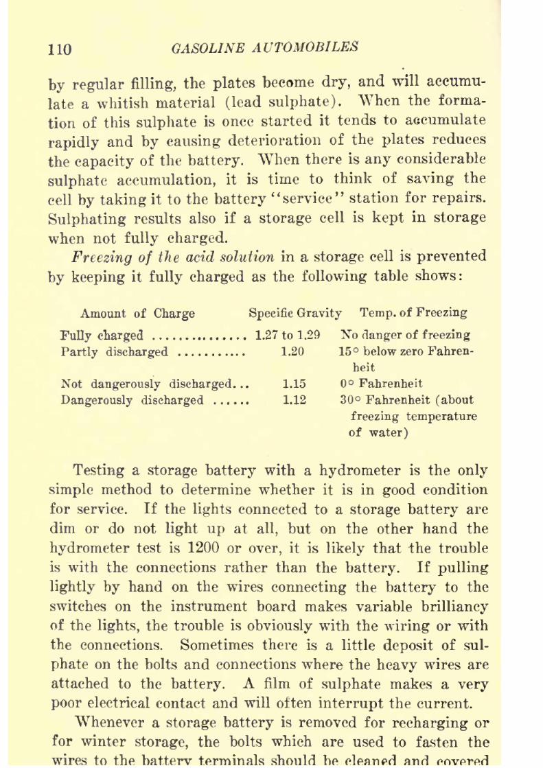
8/9/2019 (1921) Gasoline Automobiles
http://slidepdf.com/reader/full/1921-gasoline-automobiles 122/280
110 GASOLINE AUTOMOBILES
by regular filling, the plates become dry, and will accumu-
late a whitish material (lead sulphate). When the forma-
tion of this sulphate is once started it tends to accumulate
rapidly and by causing deterioration of the plates reduces
the capacity of the battery. When there is any considerable
sulphate accumulation, it is time to think of saving the
cell by taking it to the battery "service" station for repairs.
Sulphating results also if a storage cell is kept in storage
when not fully charged.Freezing of the acid solution in a storage cell is prevented
by keeping it fully charged as the following table shows:
Amount of Charge Specific Gravity Temp, of Freezing
Fully charged 1.27 to 1.29 No danger of freezing
Partly discharged 1.20 15 below zero Fahren-
heit
Not dangerously discharged... 1.15 Fahrenheit
Dangerously discharged 1.12 30 Fahrenheit (about
freezing temperature
of water)
Testing a storage battery with a hydrometer is the only
simple method to determine whether it is in good condition
for service. If the lights connected to a storage battery are
dim or do not light up at all, but on the other hand the
hydrometer test is 1200 or over, it is likely that the trouble
is with the connections rather than the battery. If pulling
lightly by hand on the wires connecting the battery to the
switches on the instrument board makes variablebrilliancy
of the lights, the trouble is obviously with the wiring or with
the connections. Sometimes there is a little deposit of sul-
phate on the bolts and connections where the heavy wires are
attached to the battery. A film of sulphate makes a very
poor electrical contact and will often interrupt the current.
Whenever a storage battery is removed for recharging or
for winter storage, the bolts which are used to fasten the
wires to
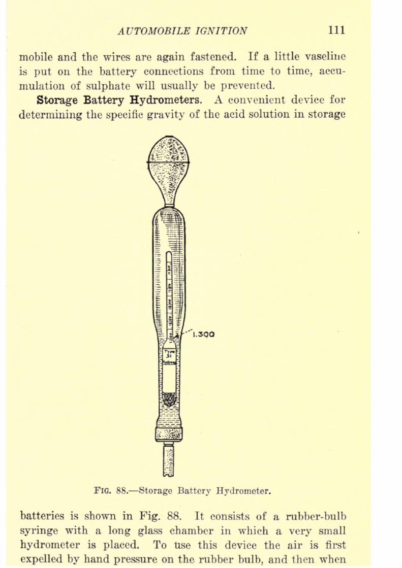
8/9/2019 (1921) Gasoline Automobiles
http://slidepdf.com/reader/full/1921-gasoline-automobiles 123/280
AUTOMOBILE IGNITION 111
mobile and the wires are again fastened. If a little vaseline
is put on the battery connections from time to time, accu-
mulation of sulphate will usually be prevented.
Storage Battery Hydrometers. A convenient device for
determining the specific gravity of the acid solution in storage
"1.300
FIG. 88. Storage Battery Hydrometer.
batteries is shown in Fig. 88. It consists of a rubber-bulb
syringe with a long glass chamber in which a very small
hydrometer is placed. To Use this device the air is first
expelled by hand pressure on the rubber bulb, and then when

8/9/2019 (1921) Gasoline Automobiles
http://slidepdf.com/reader/full/1921-gasoline-automobiles 124/280
112 GASOLINE AUTOMOBILES
be tested, the hand pressure on the bulb is released. By
this operation some of the acid solution from the cell will
be drawn by suction into the glass chamber. The hydrometer
inside the glass chamber will float in the solution, and the
reading on its scale at the surface of the liquid denotes the
specific gravity. The sample of the solution should be care-
fully put back into the same cell from which it was taken.
This is easily done by again putting the narrow stem of the
syringe into the filling tube of the cell and pressing on the
rubber bulb till all the solution is forced out.
Direct and Alternating Current. There are two kinds
of current obtainable for electrical services: (1) direct cur-
rent, and (2) alternating current. Direct current always
flows continuously in one direction through its conductor,
which is commonly a wire. Every kind of electric battery
generates direct current. In charging and recharging storage
batteries only direct current is used. Alternating current,
on the other hand, is constantly reversing its direction, flow-
ing first in one direction and then in the other. The changes
in direction are very rapid, running into hundreds per minute.
Rectifier for Alternating Current. Before alternating
current may be used in charging storage batteries it is changed
to direct current by a device called a rectifier. A rectifier
made by the General Electric Company for connection to
an electric lamp socket is shown in Fig. 89. Such rectifiers
are usually designed to give a charging current of about four
amperesfor the three
tosix
cells in an automobile storagebattery. A small apparatus of this kind suitable for use
in a small garage can be purchased for about fifteen dollars.
Charging Storage Batteries with Lighting Current.
Where direct current is furnished by local light and power
plants* a rectifier is unnecessary in charging storage bat-
teries. The voltage of the local lighting system (usually 110
volts) is ordinarily too high for charging purposes, for if
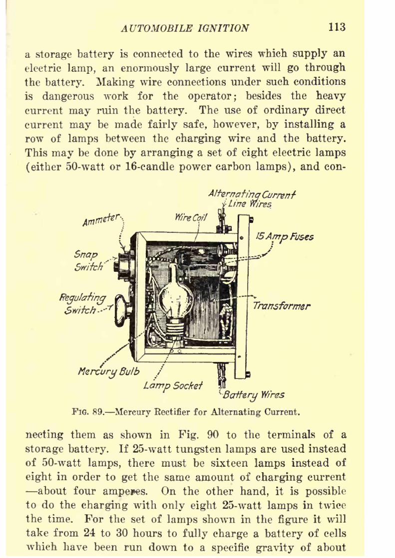
8/9/2019 (1921) Gasoline Automobiles
http://slidepdf.com/reader/full/1921-gasoline-automobiles 125/280
AUTOMOBILE IGNITION 113
a storage battery is connected to the wires which supply an
electric lamp, an enormously large current will go through
thebattery. Making
wire connections under such conditions
is dangerous work for the operator; besides the heavy
current may ruin the battery. The use of ordinary direct
current may be made fairly safe, however, by installing a
row of lamps between the charging wire and the battery.
This may be done by arranging a set of eight electric lamps
(either 50-watt or 16-candle power carbon lamps), and con-
A!ferr?at/'r?q Current'Line Wires
Regulating
Switch-"'1'
Mercury Bulb
Lamp Socket^
Wires
FIG. 89. Mercury Rectifier for Alternating Current.
necting them as shown in Fig. 90 to the terminals of a
storage battery. If 25-watt tungsten lamps are used instead
of 50-watt lamps, there must be sixteen lamps instead of
eight in order to get the same amount of charging current
about four ampejes. On the other hand, it is possible
to do the charging with only eight 25-watt lamps in twice
the time. For the set of lamps shown in the figure it will
take from 24 to 30 hours to fully charge a battery of cells
which have been run down to a specific gravity of about
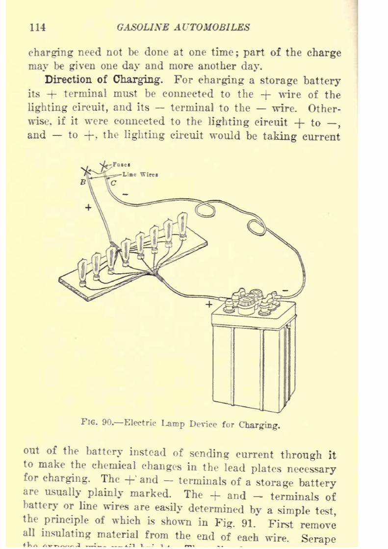
8/9/2019 (1921) Gasoline Automobiles
http://slidepdf.com/reader/full/1921-gasoline-automobiles 126/280
114 GASOLINE AUTOMOBILES
charging need not be done at one time; part of the charge
may be given one day and more another day.
Direction of
Charging.For
charginga
storage batteryits + terminal must be connected to the -}- wire of the
lighting circuit, and its terminal to the wire. Other-
wise, if it were connected to the lighting circuit + to,
and to -J-, the lighting circuit would be taking current
FIG. 90. Electric Lamp Device for Charging.
out of the battery instead of sending current through it
to make the chemical changes in the lead plates necessaryfor charging. The +' and - terminals of a storage batteryare usually plainly marked. The + and - terminals of
battery or line wires are easily determined by a simple testthe principle of which is
shown in Fig. 91. First removeall insulating material from the end of each wire. Scrape

8/9/2019 (1921) Gasoline Automobiles
http://slidepdf.com/reader/full/1921-gasoline-automobiles 127/280
AUTOMOBILE IGNITION 115
cup of water to which a tablespoonful of common salt has been
added. If the ends are held about one-quarter inch apart
inthis salt
water solution, small bubbles willrise
fromthe
wire which is the (negative) terminal. This is the wire
to be attached to the terminal of the battery for charging.
The other wire is -j- (positive) and should be connected to
the -j- terminal of the battery. When making this test if
HydGaa Bubblee\
FIG. 91. Testing Electric Wires.
the bubbles do not appear, the wiring may be defective andan expert should be consulted.
Series and Parallel Connections. As a single storage or
dry cell gives too little voltage for practical purposes in auto-
mobile operation, several cells must be connected together to
get the necessary voltage for ignition, lighting and start-
FIG. 92. Cells in Series.
ing; that is, to get from six to eight volts. The way
four dry cells of one and a half volts each can be connected
to get a total of six volts is shown diagrammatically in
Fig. 92. By this arrangement the carbon terminal (-)-)
of one cell is connected to the zinc terminal ( ) of thenext. This is called connecting the cells in series. By this

8/9/2019 (1921) Gasoline Automobiles
http://slidepdf.com/reader/full/1921-gasoline-automobiles 128/280
116 GASOLINE AUTOMOBILES
total voltage is equal to the number of cells multiplied by
the volts of each cell. A dry ceU is tested for amperes,
by connecting its two terminals together by an instrument
(ammeter). It is safe to do this with a dry cell but should
never be attempted with a storage cell because the latter
can give an enormous and dangerous current when short cir-
cuited.
If all the carbon positive (+ ) terminals are connected
together and similarly all the zinc negative ( ) terminals,
as in Fig. 93, the four cells are connected in parallel. Inthis way the amount of current is increased and the total
amperes of the set is equal to the amperes of one cell multi-
X^fc/ Xu/ \W^ N*^ N **.-..
FIG. 93. Cells in Parallel.
plied by the number of cells. The volts are the same as of
one cell.
The following brief rule is easily remembered. To increase
the volts or voltage, connect the cells together in a series
arrangement, as in Pig. 92. To increase the amperes or
amount of current, connect the cells in parallel, as in Fig. 93.
Magnetismand
Electricity.In order to have a clear
understanding of the electrical apparatus used in auto-
mobiles, one should know the relation between magnet-
ism and electricity. Magnetism suggests the attraction
of pieces of iron or steel to a magnet. The field of
influence, called the magnetic field, of a magnet is strongest
at its ends. The close relation of electricity to magnetism
is easily shown by winding a wire carrying an electric current
around a bar of iron and the of the
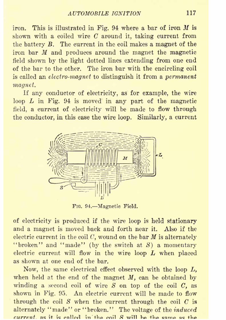
8/9/2019 (1921) Gasoline Automobiles
http://slidepdf.com/reader/full/1921-gasoline-automobiles 129/280
AUTOMOBILE IGNITION 117
iron. This is illustrated in Fig. 94 where a bar of iron M is
shown with a coiled wire C around it, taking current from
the battery B. The current in the coil makes a magnet of the
iron bar M and produces around the magnet the magnetic
field shown by the light dotted lines extending from one end
of the bar to the other. The iron bar with the encircling coil
is called an electro-magnet to distinguish it from a permanent
magnet.
If any conductor of electricity, as for example, the wire
loop L in Fig. 94 is moved in any part of the magnetic
field, a current of electricity will be made to flow through
the conductor, in this case the wire loop. Similarly, a current
FIG. 94. Magnetic Field.
of electricity is produced if the wire loop is held stationary
and a magnet is moved back and forth near it. Also if the
electric current in the coil C, wound on the bar M is alternately
"broken" and "made" (by the switch at S) a momentary
electriccurrent will flow in the wire loop L when placed
as shown at one end of the bar.
Now, the same electrical effect observed with the loop L,
when held at the end of the magnet M, can be obtained by
winding a second coil of wire 8 on top of the coil C, as
shown in Fig. 95. An electric current will be made to flow
through the coil 8 when the current through the coil C is
alternately' '
made' '
or' '
broken.' '
The voltage of the induced

8/9/2019 (1921) Gasoline Automobiles
http://slidepdf.com/reader/full/1921-gasoline-automobiles 130/280
118 GASOLINE AUTOMOBILES
voltage in the coil C if the number of turns or rings is the
same in each coil. If, however, the numbers of turns in the
coil S is ten thousand times as large as the number of turns
in the coil C, then the voltage in S is ten thousand times as
large as that in C. A large quantity of current (aniperes)
FIG. 95. Simple Induction Coil.
at the high, voltage produced by such a coil would be danger-
ous, but there is only a small current in any device of this
kind likely to be used on an automobile, so that a shock from
it will give only an uncomfortable feeling. But do not ever
connect together (short circuit) the terminals of a storage
FIG. 96. Winding of Wires for Inducing High-
Voltage Current.
battery. Fig. 96 shows very clearly the arrangement of wires
inducing a high voltage current.
The necessary electric spark for practically all kinds of
automobile is

8/9/2019 (1921) Gasoline Automobiles
http://slidepdf.com/reader/full/1921-gasoline-automobiles 131/280
AUTOMOBILE IGNITION 119
the points of two electric wires of an ignition device called
a spark plug. In order to make electricity jump across the
air gap in a spark plug a high electric pressure of at least
nine thousand volts is needed. Most ignition systems using
batteries have three storage cells or six dry cells. Six dry
cells, for example, can give when new only about nine volts,
and this low voltage, therefore, must be raised to nine thou-
sand volts to force an electric spark with certainty across a
one thirty-second inch air gap of a spark plug. In practically
all appliances using electric current from batteries for engine
ignition by means of spark plugs, the necessary increase in
voltage is obtained by the use of a coil like S in Fig. 95,
having a large number of turns. By this method, the required
nine thousand volts can be obtained from six dry cells (nine
volts) bythe use of a device similar to the one
shown, havingone thousand times as many turns on the coil S as on the
coil C* For practical reasons the low voltage coil C is made
of coarse wire and the high voltage coil 8 of fine wire.
Spark Plugs. A spark plug has for its essential parts two
wires which are thoroughly insulated electrically from each
other and are close enough together at their ends to make a
short air gap. Except for minor details, the construction
of all kinds of spark plugs is about the same. The one shown
in Fig. 97 is an example of standard construction. The
wire which brings the high voltage electric current from the
fine-wire winding of the induction coil S (Fig. 95) to the spark
plug, is fastened to the top T, so as to make electrical contact
with a wire W, made of special heat-resisting nickel steel
alloy. This wire W extends down through the central por-
tion or core, which is made of porcelain or mica. Outside
the central core is a steel ring or "body" B with a screw thread
to which is attached a curved wire V which projects inward
* The electrical principles involved are general in application ;that
is, the voltage in the coil -S (called the secondary) is to the voltage in
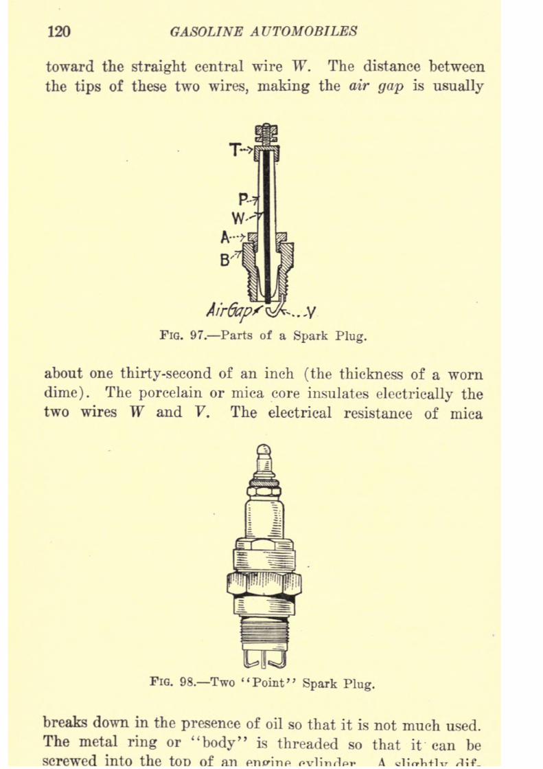
8/9/2019 (1921) Gasoline Automobiles
http://slidepdf.com/reader/full/1921-gasoline-automobiles 132/280
120 GASOLINE AUTOMOBILES
toward the straight central wire W. The distance between
the tips of these two wires, making the air gap is usually
FIG. 97. Parts of a Spark Plug.
about one thirty-second of an inch (the thickness of a worn
dime). The porcelain or mica core insulates electrically the
two wires W and V. The electrical resistance of mica
FIG. 98. Two "Point" Spark Plug.
breaks down in the presence of oil so that it is not much used.
The metal ring or "body" is threaded so that it can be
screwed into the

8/9/2019 (1921) Gasoline Automobiles
http://slidepdf.com/reader/full/1921-gasoline-automobiles 133/280
AUTOMOBILE IGNITION 121
ferent spark plug with two"points" or air gaps is shown in
Fig. 98. A more commonly used type is shown in Fig. 99.
Afr&ap..
FIG. 99. Single "Point' Spark Plug.
Battery Ignition Systems. The outline drawing shown
in Fig. 95 shows the essential parts of all modern battery
ignition systems. It includes a battery, an induction coil
with windings of coarse and fine wire, a circuit breaker or
switch with movable contact points, and a spark plug with
the wires for connecting these parts as they might be applied
to a single cylinder engine. Practically all automobile engines,
however, have four or more cylinders, and each cylinder
requires a separate device for the ignition of the explosive
mixture. Figs. 100 and 101 show a diagram of a typical
battery ignition system for a four cylinder engine. The top
view of this diagram (Fig. 100) shows the arrangement of
wires carrying the high-voltage current from the device
called the distributor to the individual spark plugs. The
order of numbers on the distributor is not the same as the
consecutive numbers on the spark plugs. There is this differ-
encein
numbering becausethe distributor
determines thefir-
ing order of the cylinders. (See page 45.) Below this draw-
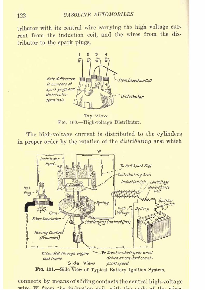
8/9/2019 (1921) Gasoline Automobiles
http://slidepdf.com/reader/full/1921-gasoline-automobiles 134/280
122 GASOLINE AUTOMOBILES
tributor with its central wire carrying the high voltage cur-
rent from the induction coil, and the wires from the dis-
tributorto the
spark plugs.
Note difference
in numbers of
sparkplugs
and
distributor
terminals
Top View
FIG. 100. High-voltage Distributor.
The high-voltage current is distributed to the cylinders
in proper order by the rotation of the distributing arm which
w
To No.4Spark Plug
DistributingArm
Induction Coil ,-Lorf
Vb/ftye/ Res&isfance
Groundedthrough engine
^--'Br Breakershaftgear wheel
and frame driven at one-haIferank-
Side View shaftspeed
FlG. 101. Side^View of Typical Battery Ignition System.
connects by means of sliding contacts the central high-voltage
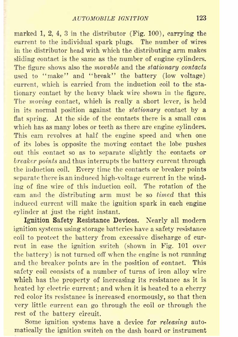
8/9/2019 (1921) Gasoline Automobiles
http://slidepdf.com/reader/full/1921-gasoline-automobiles 135/280
AUTOMOBILE IGNITION 123
marked 1, 2, 4, 3 in the distributor (Fig. 100), carrying the
current to the individual spark plugs. The number of wires
in the distributor head with which the distributing arm makessliding contact is the same as the number of engine cylinders.
The figure shows also the movable and the stationary contacts
used to "make" and "break" the battery (low voltage)
current, which is carried from the induction coil to the sta-
tionary contact by the heavy black wire shown in the figure.
The moving contact, which is really a short lever, is held
in its normal position against the stationary contact by a
flat spring. At the side of the contacts there is a small cam
which has as many lobes or teeth as there are engine cylinders.
This cam revolves at half the engine speed and when one
of its lobes is opposite the moving contact the lobe pushes
out this contact so as to separate slightly the contacts or
breaker points and thus interrupts the battery current through
the induction coil. Every time the contacts or breaker points
separate there is an induced high-voltage current in the wind-
ing of fine wire of this induction coil. The rotation of the
cam and the distributing arm must be so timed that this
induced current will make the ignition spark in each engine
cylinderat
justthe
rightinstant.
Ignition Safety Resistance Devices. Nearly all modern
ignition systems using storage batteries have a safety resistance
coil to protect the battery from excessive discharge of cur-
rent in case the ignition switch (shown in Fig. 101 over
the battery) is not turned off when the engine is not running
and the breaker points are in the position of contact. This
safety coil consists of a number of turns of iron alloy wire
which has the property of increasing its resistance as it is
heated by electric current;and when it is heated to a cherry
red color its resistance is increased enormously, so that then
very little current can go through the coil or through the
rest of the battery circuit.
Some ignition systems have a device for releasing auto-
matically the ignition switch on the dash board or instrument
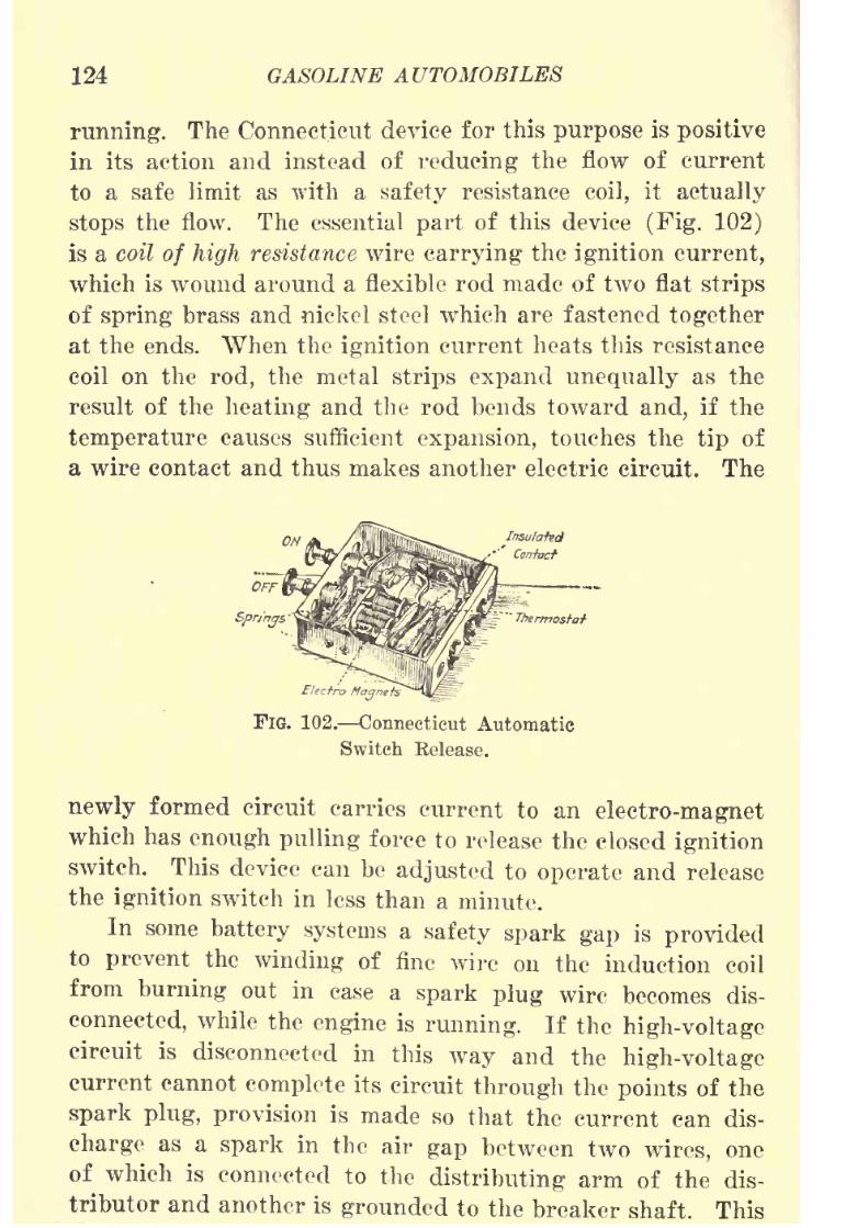
8/9/2019 (1921) Gasoline Automobiles
http://slidepdf.com/reader/full/1921-gasoline-automobiles 136/280
124 GASOLINE AUTOMOBILES
running. The Connecticut device for this purpose is positive
in its action and instead of reducing the flow of current
to a safe limit as with a safety resistance coil, it actually
stops the flow. The essential part of this device (Fig. 102)
is a coil of high resistance wire carrying the ignition current,
which is wound around a flexible rod made of two flat strips
of spring brass and nickel steel which are fastened together
at the ends. When the ignition current heats this resistance
coil on therod,
the metalstrips expand unequally
as the
result of the heating and the rod bends toward and, if the
temperature causes sufficient expansion, touches the tip of
a wire contact and thus makes another electric circuit. The
Insulated
Confacf
ElectroMagnets
FlG. 102. Connecticut Automatic
Switch Release.
newly formed circuit carries current to an electro-magnetwhich has enough pulling force to release the closed ignition
switch. This device can be adjusted to operate and release
the ignition switch in less than a minute.
In some battery systems a safety spark gap is providedto prevent the winding of fine wire on the induction coil
from burning out in case a spark plug wire becomes dis-
connected, while the engine is running. If the high-voltagecircuit is disconnected in this way and the high-voltagecurrent cannot complete its circuit through the points of the
spark plug, provision is made so that the current can dis-
charge as a spark in the air gap between two wires, one
of which is connected to the distributing arm of the dis-
tributor and another is grounded to the breaker shaft. This

8/9/2019 (1921) Gasoline Automobiles
http://slidepdf.com/reader/full/1921-gasoline-automobiles 137/280
AUTOMOBILE IGNITION 125
its points than eleven thirty-seconds of an inch. Otherwise
the high-voltage current may jump across the safety spark
gap rather than across the air gaps of the spark plugs in
the cylinders. If this occurs, imperfect ignition will result.
Automatic Spark Advance. In a battery ignition system
the amount of current (amperes) that can go through the
various resistances does not depend on the speed of the
engine. The amount of current is practically the same
whether the
enginespeed is
highor low. At low engine
speeds there are few ignitions with a relatively long time
between. For each ignition at low speed, therefore, a strong,
high-voltage current is generated in the coil to make a
"fat" spark at the spark plugs and this system gives excep-
tionally good ignition sparks for starting the engine. AVith
these good conditions at low speeds, ignition in the engine
cylinders is almost instantaneous. At high engine speeds,
however, battery systems can have little time for generating
the high-voltage current for ignition, and the sparks at the
spark plugs are. weak and produce slower combustion. In
order, therefore, to have ignition of the explosive mixture
in the cylinders practically complete at the beginning of
each explosion stroke, it is desirable, when battery systems are
used, to advance the spark automatically by some mechanical
means; that is, to make the spark come earlier at high than
at low speeds. Otherwise the engine will waste gasoline and
oil and will be easily overheated.
The position of the spark as to advance or retard can
be controlled by shifting by hand the spark lever on the
steering wheel, but this requires the constant attention of
the driver. Provision is therefore made in nearly all battery
ignition systems for the automatic advance and retard of
the ignition spark by the use of revolving governor weights
mounted on the same shaft with the breaker points and the
distributing arm. A commonly used method is to fasten
the governor weights to a short hollow shaft (Fig. 103) whichcarries also the distributing arm and the cam for moving
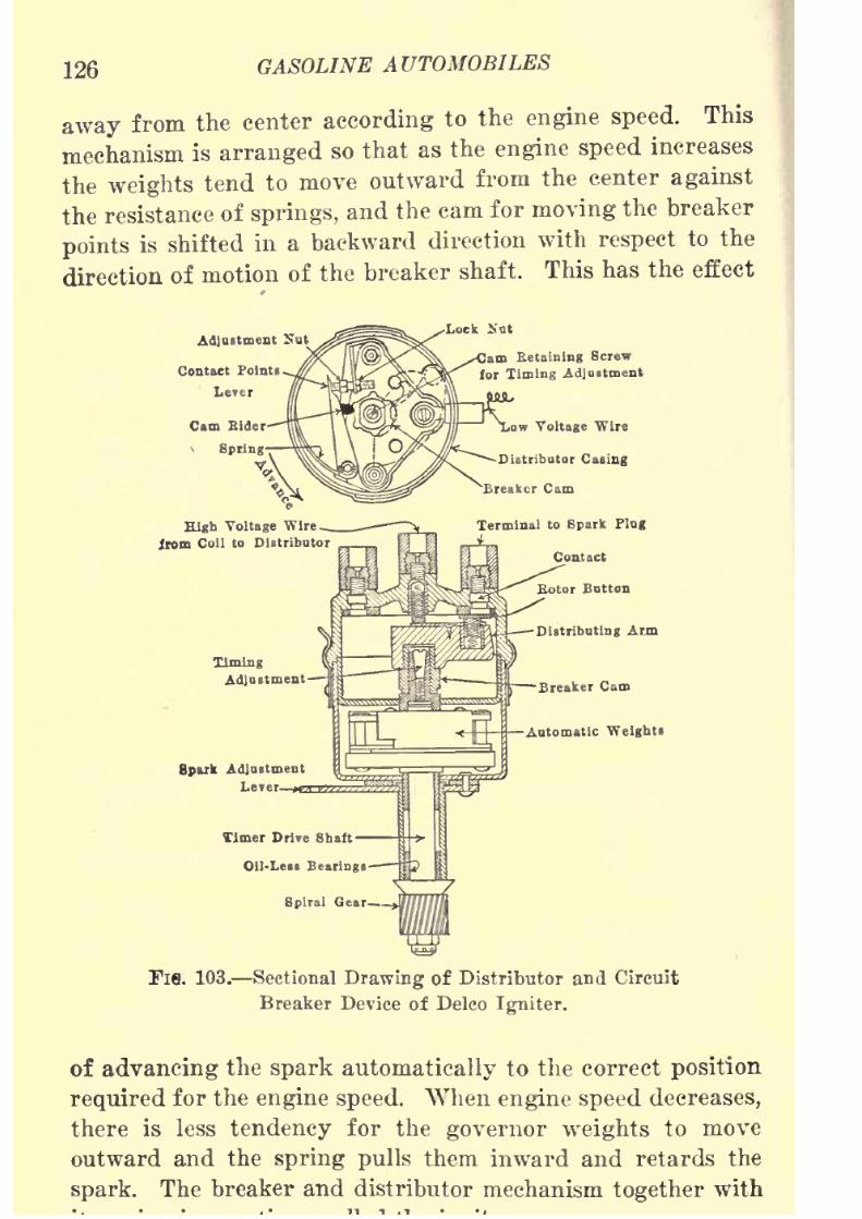
8/9/2019 (1921) Gasoline Automobiles
http://slidepdf.com/reader/full/1921-gasoline-automobiles 138/280
126 GASOLINE AUTOMOBILES
away from the center according to the engine speed. This
mechanism is arranged so that as the engine speed increases
the weights tend to move outwardfrom the center
againstthe resistance of springs, and the cam for moving the breaker
points is shifted in a backward direction with respect to the
direction of motion of the breaker shaft. This has the effect
Contact Points
Lever
High Voltage Wirom Coll to Distributor
m Retaining Screw
for Timing Adjustment
SparkAdjust
L
Timer Drive Shaft
Oil-Le.B Bearings
Spiral Gear
Fl6. 103. Sectional Drawing of Distributor and Circuit
Breaker Device of Delco Igniter.
of advancing the spark automatically to the correct position
required for the engine speed. When engine speed decreases,
there is less tendency for the governor weights to move
outward andthe
spring pulls them inward andretards the
spark. The breaker and distributor mechanism together with

8/9/2019 (1921) Gasoline Automobiles
http://slidepdf.com/reader/full/1921-gasoline-automobiles 139/280
AUTOMOBILE IGNITION 127
Vibrating Induction Coil. Fig. 104 shows diagrammat-
ically an induction coil of the vibrating type and an engine
cylinder, withits
spark plug. This typeof coil is
used onFord automobiles. The iron magnet in the coil is marked
M. The winding of heavy wire C receives the low-voltage
electric current from the battery B, which produces in the
winding of fine wire 8 the high voltage current needed for
the spark plug P. In the operation of this apparatus the
current from one end of the battery B goes through the wire
C to the left-hand end of the device. From the other end
High Voltage Circuit
Fie. 104. Vibrating Ignition Coil.
of the battery a wire goes to the circuit breaker T, and from
there through the coil to the base of vibrator V. To complete
the circuit the current goes from the left-hand end of battery
to the screwholder H, through the screw 0, down the flexible
blade of the vibrator V, and then to the right-hand end of
the low voltage winding C. At the upper end of the flexible
vibrator V is a small piece of soft iron. Now in the operation
of this device, when the electric current goes through the
winding (7, the iron bar M is magnetized and causes this small
piece of iron on the vibrator V to be attracted toward it.
This magnetic attraction bends the flexible blade of thevibrator and pulls it away from the end of the screw O. As

8/9/2019 (1921) Gasoline Automobiles
http://slidepdf.com/reader/full/1921-gasoline-automobiles 140/280
128 GASOLINE AUTOMOBILES
between O and T, the iron bar M loses its magnetism and
its attraction for the small piece of iron, so that the flexible
vibrator Vreturns to a vertical
position.
When the vibrator
is vertical, it again brings together the contact points between
O and V, and electric current once more flows through the
winding C to magnetize the iron bar M, which by its magnetic
attraction breaks the electric circuit as before. The sequence
is repeated with great rapidity when the circuit breaker T
is in the position so that the cam A touches the metal contact
D on the wire connected to the right-hand end of the coil.
The battery current does not go to the spark plugs at all.
The operating principle of this coil and its vibrator is exactly
the same as that of an ordinary electric door bell.
The result of rapidly opening and closing the contact
points between the screw and the vibrator V is to make
a high-voltage induced current in the high-voltage winding8. To accomplish this, there must always be some kind of
circuit breaker in the battery circuit. The instant the points
of the circuit breaker connect, there is a momentary induced
current in the winding 8, and if there is a spark plug con-
nected by wires to this winding, the induced current produces
a spark at the "points" of the spark plug. The instant the
circuit breaker starts the battery current through the winding
of coarse wire C, the magnetism due to this current goes
through the winding of fine wire 8, and induces the high
voltage current. The ends of the winding 8 are connected
to the binding posts at the top. Either of these posts maybe connected by a wire to the screw cap of the spark plug P
in the engine cylinder. As applied to an automobile engine,
the wire from the other post is usually attached securely to
the engine casting or frame or to some part of the automobile
in metallic contact with the engine cylinders. A wire attached
to the metal of the engine in this way is grounded. The high-
voltage electric current going through this grounded wire
will pass through the metal of the
engineto the
body of thespark plug in the top of the engine cylinder. Every time
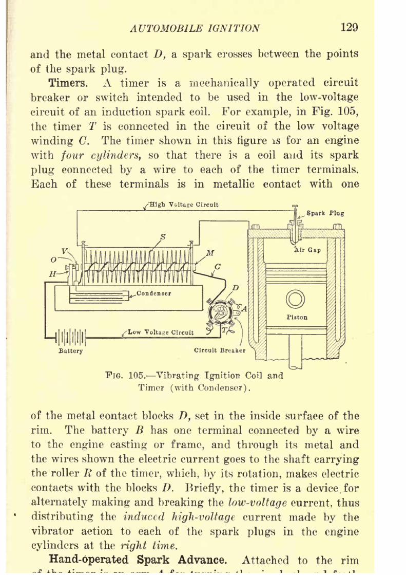
8/9/2019 (1921) Gasoline Automobiles
http://slidepdf.com/reader/full/1921-gasoline-automobiles 141/280
AUTOMOBILE IGNITION 129
and the metal contact D, a spark crosses between the points
of the spark plug.
Timers. A timer is a mechanically operated circuit
breaker or switch intended to be used in the low-voltage
circuit of an induction spark coil. For example, in Fig. 105,
the timer T is connected in the circuit of the low voltage
winding C. The timer shown in this figure is for an engine
with four cylinders, so that there is a coil and its spark
plug connected by a wire to each of the timer terminals.
Each of these terminals is in metallic contact with one
FlG. 105. Vibrating Ignition Coil and
Timor (with Condenser).
of the metal contact blocks Z), set in the inside surface of the
rim. The battery B has one terminal connected by a wire
to the engine casting or frame, and through its metal and
the wires shown the electric current goes to the shaft carrying
the roller R of the timer, which, by its rotation, makes electric
contacts with the blocks D. Briefly, the timer is a device. for
alternately making and breaking the low-voltage current, thus
distributing the induced high-voltage current made by the
vibrator action to each of the spark plugs in the engine
cylindersat the
righttime.
Hand-operated Spark Advance. Attached to the rim

8/9/2019 (1921) Gasoline Automobiles
http://slidepdf.com/reader/full/1921-gasoline-automobiles 142/280
130 GASOLINE AUTOMOBILES
on its shaft. If the rim of the tinier is turned in the direc-
tion its central shaft is moving, the spark will occur later in
the stroke of each of the engine cylinders, while if moved
in the opposite direction the spark will occur earlier. In
the former case the spark is retarded and in the latter it is
advanced. On practically all automobiles this arm A on the
rim is connected by a rod to a lever on the steering wheel,
so that advancing or retarding the spark is under the control
of the person operating the automobile.
Distributors or timers for six-, eight-, or twelve-cylinder
engines are similar to those explained except that they have
six, eight, or twelve terminals in the rim instead of four.
Condensers. In the operation of the vibrator V of a
vibrating induction coil (Fig. 105), there is a tendency to draw
out a long"fat
"spark at the contact points betwene and V
every time the currentis
stopped. This drawing outof the
spark, if not prevented, would have the effect of wasting
much current, weakening the spark at the spark plug points,
and burning off the contact points of the vibrator. To reduce
these ill effects a condenser shown at the bottom of the figure
is provided as part of a complete induction or spark coil. It is
connected by small wires "across" the air gap made at the
contact points as shown. In other words, one terminal of the
condenser is connected to the low-voltage wiring on one side
of the contact points, and the other terminal to the other side.
The condenser in its action is somewhat like a shock absorber
on the body of an automobile.
Condenser Construction. A condenser consists of a
number of sheets of tinfoil separated from each other bysheets of oiled paper. Every alternate tinfoil sheet is con-
nected to the bottom of the screw-holder H (Fig. 105), the
ends of the other tinfoil sheets are connected to the bottom
of the vibrator V. If a condenser is attached to an induction
coil of any kind as described and the battery current goingto the coil is stopped, the battery current, instead of following
the vibrator points and making a long spark, spreads over

8/9/2019 (1921) Gasoline Automobiles
http://slidepdf.com/reader/full/1921-gasoline-automobiles 143/280
AUTOMOBILE IGNITION 131
is "stored "'to be given back to the circuit when these contact
points again come together. By this quick and clean break-
ingof the
low-voltage current,an induced current of
highervoltage is obtained than would otherwise be the case. Acondenser increases the size of the spark about twenty-five
times. Condensers are often made by winding together two
long strips of tinfoil separated by paraffine paper.
The condenser on an induction coil may be injured if the
"points" of the air gap of a spark plug are too far apart.
In that case there is excessive electric stress in the condenser
which causes it to break down. If the condenser is defective
and there are large sparks at the vibrator, there will be weak
sparks at the spark plugs, but weak sparks may be also caused
by a partial breaking down of the condenser, or by a loose
wire at the condenser.
Three-terminal Induction Spark Coil. Most of the
vibrating induction coils used on automobiles have only three
terminals instead of the four terminals in Figs. 104 and 105.
It might have been stated in the description of the coil in
Fig. 105 that one wire from the high-voltage winding and
one wire from the low-voltage winding are grounded to the
engine casting. These two wires
mighthave been connected
together at the induction coil and their junction connected
through the timer (grounded) to the engine casting by a
single wire as shown in Fig. 106. In a three-terminal coil as
made for commercial use one end of the low-voltage winding
is joined to one end of the high-voltage winding and the
joining place of these two windings is connected directly to
one of the binding posts marked "common ground to timer"
as shown in Fig. 107. The other end of the low-voltage wind-
ing is connected to the binding post marked "battery," and
the other end of the high-voltage winding is connected to the
binding post marked "plug" (for spark plug). Fig. 108
shows four vibrating spark coils similar to Fig. 107 as they
would be connected to the timer and to the spark plugs ofthe cylinders of a Ford engine. The four separate coils for
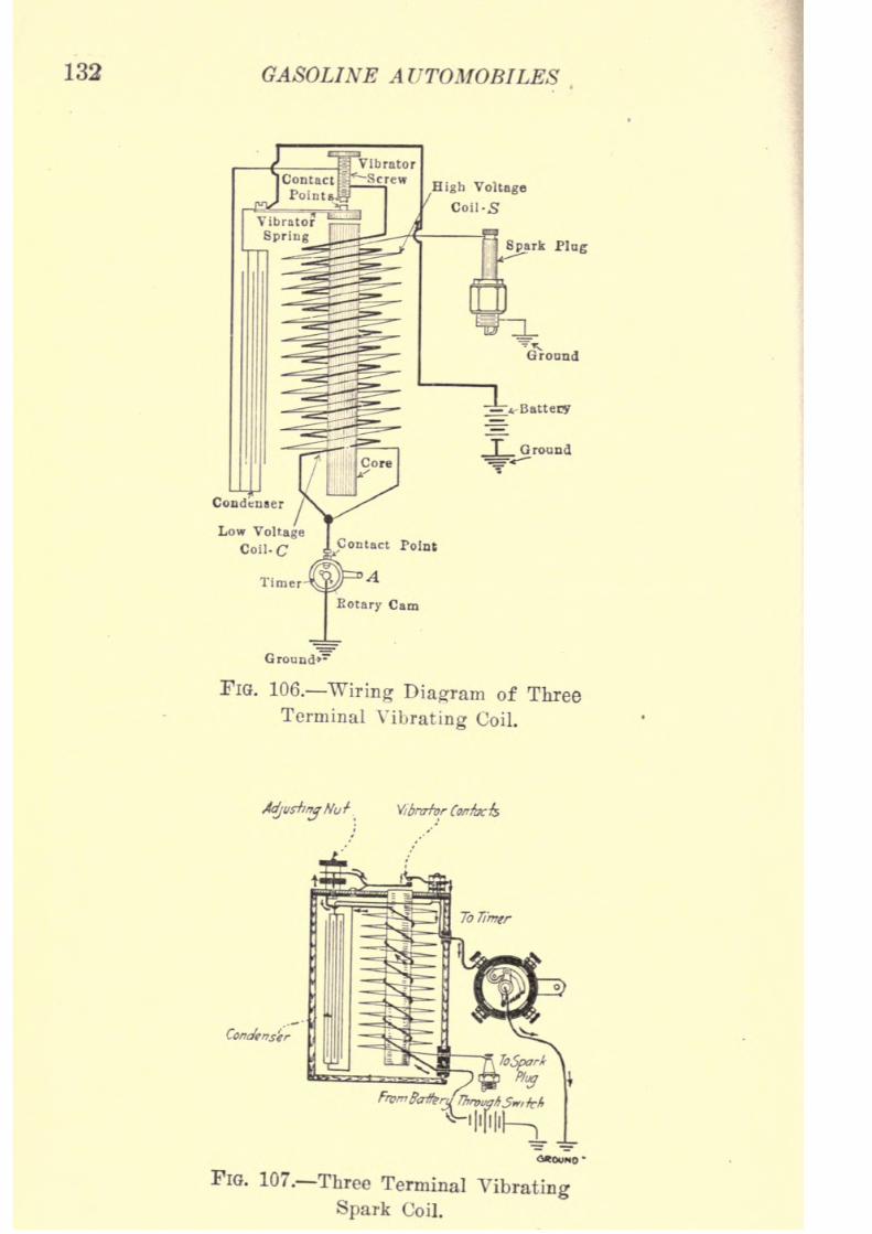
8/9/2019 (1921) Gasoline Automobiles
http://slidepdf.com/reader/full/1921-gasoline-automobiles 144/280
132 GASOLINE AUTOMOBILES
Ground*1
FlG. 106. Wiring Diagram of Three
Terminal Vibrating Coil.
AdjustingNut Vibnrtvr Corrfack
Condenser
FIG. 107. Three Terminal Vibrating
Spark Coil.
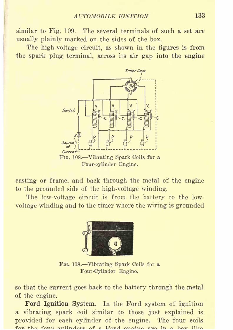
8/9/2019 (1921) Gasoline Automobiles
http://slidepdf.com/reader/full/1921-gasoline-automobiles 145/280
AUTOMOBILE IGNITION 133
similar to Fig. 109. The several terminals of such a set are
usually plainly marked on the sides of the box.
The high-voltage circuit, as shown in the figures is from
the spark plug terminal, across its air gap into the engine
FlG. 108. Vibrating Spark Coils for a
Four-cylinder Engine.
casting or frame, and back through the metal of the engine
to the grounded side of the high-voltage winding.
The low-voltage circuit is from the battery to the low-
voltage winding and to the timer where the wiring is grounded
FIG. 108. Vibrating Spark Coils for a
Four-Cylinder Engine.
so that the current goes back to the battery through the metal
of the engine.
Ford Ignition System. In the Ford system of ignition
a vibrating spark coil similar to those just explained is
provided for each cylinder of the engine. The four coils
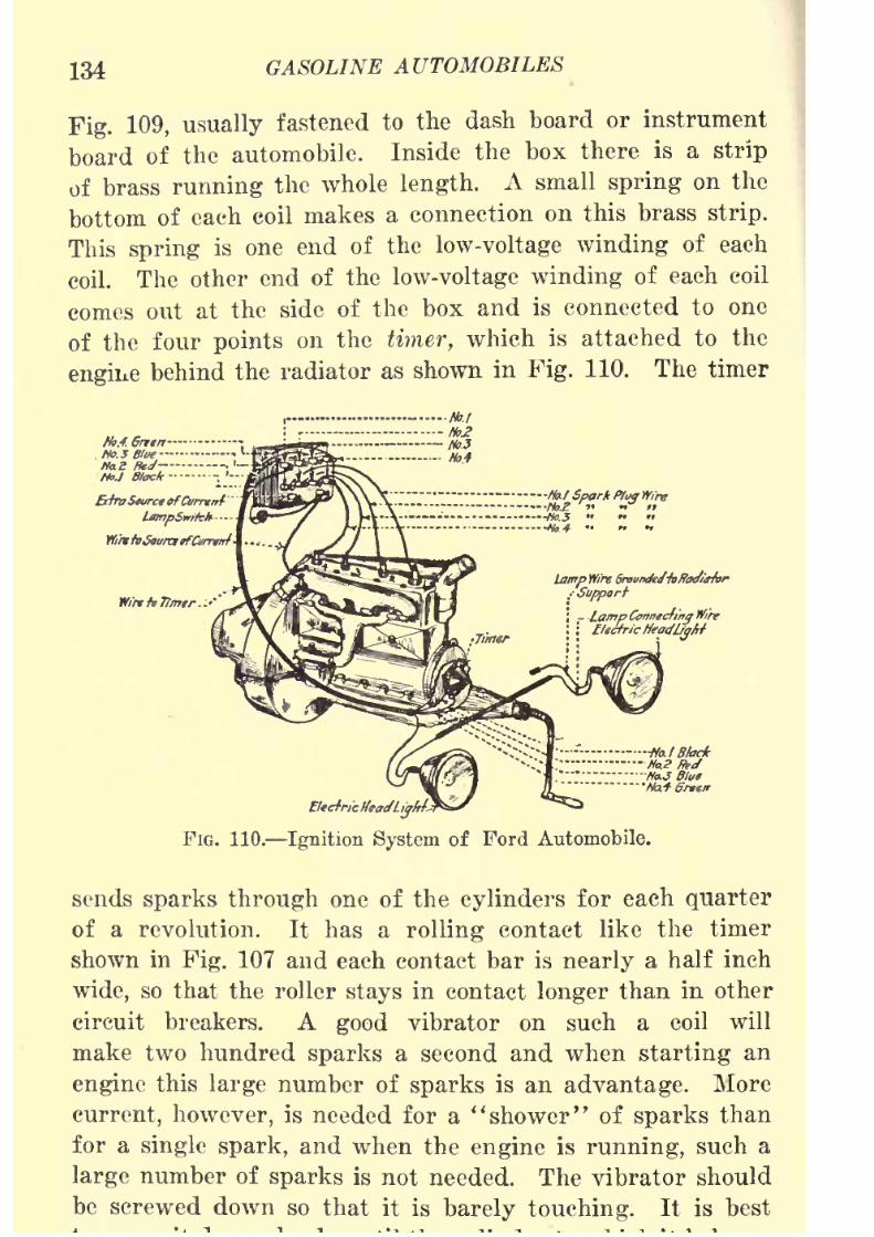
8/9/2019 (1921) Gasoline Automobiles
http://slidepdf.com/reader/full/1921-gasoline-automobiles 146/280
134 GASOLINE AUTOMOBILES
Fig. 109, usually fastened to the dash board or instrument
board of the automobile. Inside the box there is a strip
of brass running the whole length. Asmall
springon the
bottom of each coil makes a connection on this brass strip.
This spring is one end of the low-voltage winding of each
coil. The other end of the low-voltage winding of each coil
comes out at the side of the box and is connected to one
of the four points on the timer, which is attached to the
engine behind the radiator as shown in Fig. 110. The timer
No.l.Grttn -
tlo.3 giuel-
Ha Hid -,
HoJ Black -
BffraSturctofCurnnt
Lamp Wire SraunJeJ-hffaJiirhr
Wire
FIG. 110. Ignition System of Ford Automobile.
sends sparks through one of the cylinders for each quarter
of a revolution. It has a rolling contact like the timer
shown in Fig. 107 and each contact bar is nearly a half inch
wide, so that the roller stays in contact longer than in other
circuit breakers. A good vibrator on such a coil will
make two hundred sparks a second and when starting an
engine this large number of sparks is an advantage. More
current, however, is needed for a "shower" of sparks than
for a single spark, and when the engine is running, such a
large numberof
sparks is not needed. The vibrator shouldbe screwed down so that it is barely touching. It is best

8/9/2019 (1921) Gasoline Automobiles
http://slidepdf.com/reader/full/1921-gasoline-automobiles 147/280
AUTOMOBILE IGNITION 135
begins to have explosions. Sometimes the points on the
vibrator must be smoothed or scraped with sand paper. If
anengine
misses explosions regularly in one of the cylinders
it is likely one of the spark plugs is defective. If, however,
the engine runs irregularly and misses an explosion only
occasionally with sometimes a loud noise from an explosion
in the muffler, the difficulty can often be remedied by adjust-
ing the vibrator points.
Master Vibrators. In the sets of vibrating induction
coils described in the preceding Paragraphs there is a
FlG. 111. Diagram of Wiring ofMaster Vibrator Coil.
separate coil for each engine cylinder so that when the
vibrators on the coils are not operating properly, each coil
must be separately adjusted. In order to avoid the vibrator
adjustments on a number of coils and to eliminate the pos-
sibility of getting sparks of different intensity in the engine
cylinders a master vibrator is sometimes used. The adjust-
ment of this single vibrator serves for all the cylinders of
an engine and when it is installed the vibrators on the
individual coils can be screwed down so that they will not
operate. When a master vibrator is once adjusted all
cylinderswill
get ignition sparksof
practicallythe
sameintensity. It is placed in a spark coil system between the
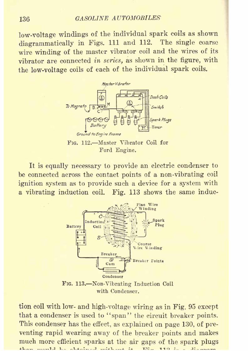
8/9/2019 (1921) Gasoline Automobiles
http://slidepdf.com/reader/full/1921-gasoline-automobiles 148/280
136 GASOLINE AUTOMOBILES
low-voltage windings of the individual spark coils as shown
diagrammatically in Figs. Ill and 112. The single coarse
wire winding of themaster vibrator coil and the wires of its
vibrator are connected in series, as shown in the figure, with
the low-voltage coils of each of the individual spark coils.
Ba-ffvry
Ground +oFngi'ne
Fn
FIG. 112. Master Vibrator Coil for
Ford Engine.
It is equally necessary to provide an electric condenser to
be connected across the contact points of a non-vibrating coil
ignition system as to provide such a device for a system with
a vibrating induction coil. Fig. 113 shows the same induc-
Plug
Condenser
FlG. 113. Non-Vibrating Induction Coil
with Condenser.
tion coil with low- and high-voltage wiring as in Fig. 95 except
that a condenser is used to "span" the circuit breaker points.
This condenser has the effect, as explained on page 130, of pre-
venting rapid wearing awayof the breaker
pointsand makes
much more efficient sparks at the air gaps of the spark plugs
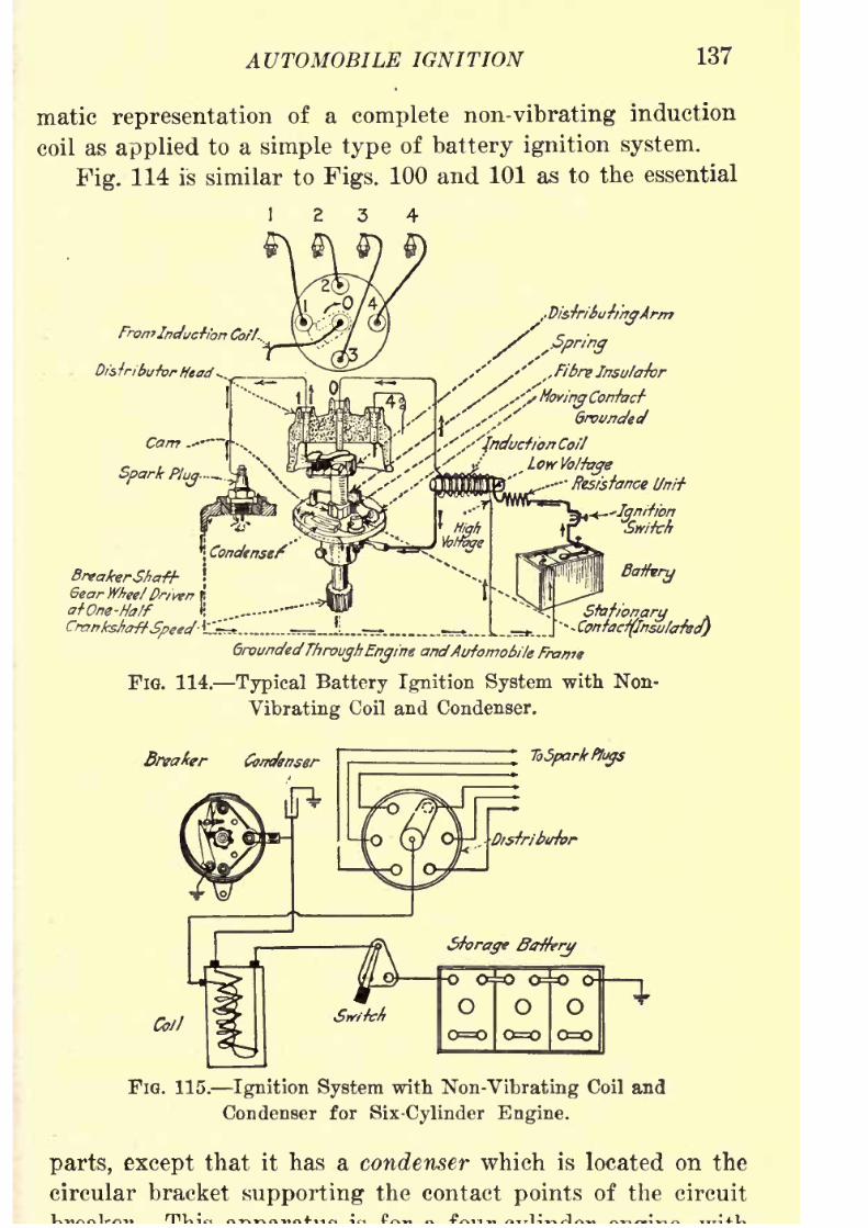
8/9/2019 (1921) Gasoline Automobiles
http://slidepdf.com/reader/full/1921-gasoline-automobiles 149/280
AUTOMOBILE IGNITION 137
matic representation of a complete non-vibrating induction
coil as applied to a simple type of battery ignition system.
Fig.114 is similar to Figs. 100 and 101 as to the essential
1234
FromInduction Co//.
Distributor Head-.
Stationary*.
Contactflrtsu/crreJ)
GroundedThroughEngine
andAutomobile Frame
FIG. 114. Typical Battery Ignition System with Non-
Vibrating Coil and Condenser.
Breaker Condenser ToSparlrfliys
FIG. 115. Ignition System with Non-Vibrating Coil and
Condenser for Six-Cylinder Engine.
parts, except that it has a condenser which is located on the
circular bracket supporting the contact points of the circuit
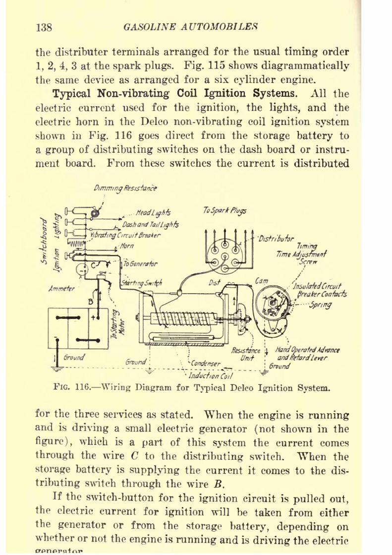
8/9/2019 (1921) Gasoline Automobiles
http://slidepdf.com/reader/full/1921-gasoline-automobiles 150/280
138 GASOLINE AUTOMOBILES
the distributer terminals arranged for the usual timing order
1, 2, 4, 3 at the spark plugs. Fig. 115 shows diagrammatically
the same device as arranged for a six cylinder engine.
Typical Non-vibrating Coil Ignition Systems. All the
electric current used for the ignition, the lights, and the
electric horn in the Delco non-vibrating coil ignition system
shown in Fig. 116 goes direct from the storage battery to
a group of distributing switches on the dash board or instru-
ment board. From these switches the current is distributed
DimmingResistance
ToSpark Plugs
Ground
InsulatedCircuit
greater Contacts
-Spring
Ground ',
'
Induction Coil
FIG. 116. Wiring Diagram for Typical Delco Ignition System.
for the three services as stated. When the engine is runningand is driving a small electric generator (not shown in the
figure), which is a part of this system the current comes
through the wire C to the distributing switch. When the
storage battery is supplying the current it comes to the dis-
tributing switch through the wire B.
If the switch-button for the ignition circuit is pulled out,
the electric current for ignition will be taken from either
the generator or from the
storage battery, dependingon
whether or not the engine is running and is driving the electric
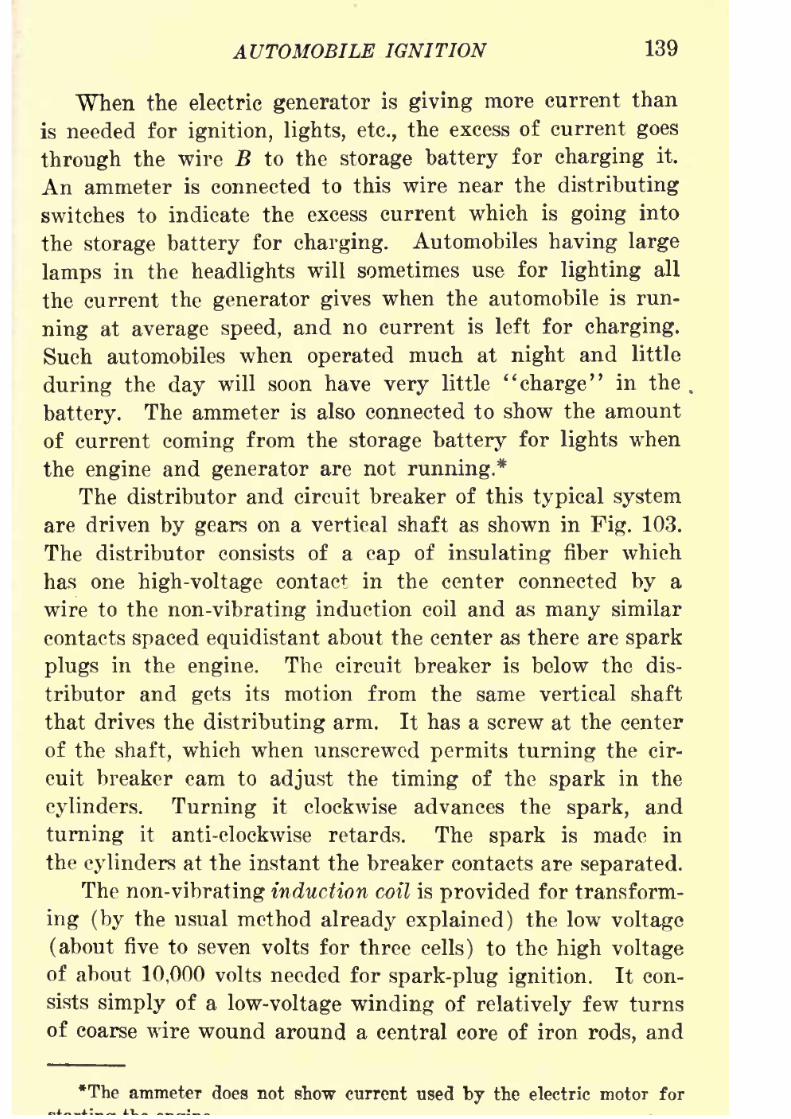
8/9/2019 (1921) Gasoline Automobiles
http://slidepdf.com/reader/full/1921-gasoline-automobiles 151/280
AUTOMOBILE IGNITION 139
When the electric generator is giving more current than
is needed for ignition, lights, etc., the excess of current goes
through the wire B to the storage battery for charging it.
An ammeter is connected to this wire near the distributing
switches to indicate the excess current which is going into
the storage battery for charging. Automobiles having large
lamps in the headlights will sometimes use for lighting all
the current the generator gives when the automobile is run-
ning at average speed, and no current is left for charging.
Such automobiles when operated much at night and little
during the day will soon have very little ''charge" in the,
battery. The ammeter is also connected to show the amount
of current coming from the storage battery for lights when
the engine and generator are not running.*
The distributor and circuit breaker of this typical system
are driven by gears on avertical
shaftas
shownin
Fig. 103.The distributor consists of a cap of insulating fiber which
has one high-voltage contact in the center connected by a
wire to the non-vibrating induction coil and as many similar
contacts spaced equidistant about the center as there are spark
plugs in the engine. The circuit breaker is below the dis-
tributor and gets its motion from the same vertical shaft
that drives the distributing arm. It has a screw at the center
of the shaft, which when unscrewed permits turning the cir-
cuit breaker cam to adjust the timing of the spark in the
cylinders. Turning it clockwise advances the spark, and
turning it anti-clockwise retards. The spark is made in
the cylinders at the instant the breaker contacts are separated.
The non-vibrating induction coil is provided for transform-
ing (by the usual method already explained) the low voltage
(about five to seven volts for three cells) to the high voltage
of about 10,000 volts needed for spark-plug ignition. It con-
sists simply of a low-voltage winding of relatively few turns
of coarse wire wound around a central core of iron rods, and
*The ammeter does not show current used by the electric motor for
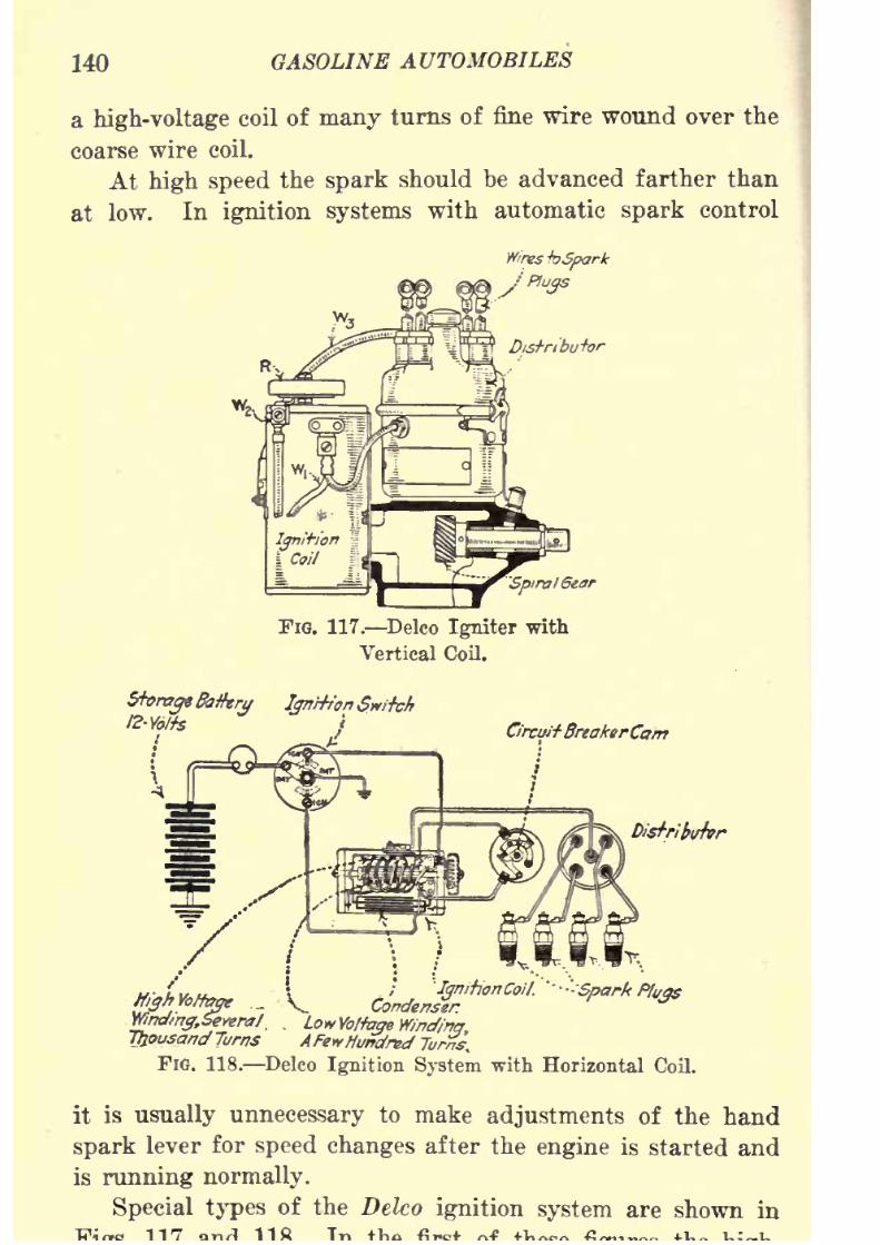
8/9/2019 (1921) Gasoline Automobiles
http://slidepdf.com/reader/full/1921-gasoline-automobiles 152/280
140 GASOLINE AUTOMOBILES
a high-voltage coil of many turns of fine wire wound over the
coarse wire coil.
Athigh speed
the
sparkshould be advanced farther than
at low. In ignition systems with automatic spark control
FIG. 117. Delco Igniter with
Vertical Coil.
Storage&#ery Imrht'on Snitch
12-Wfs}
*.%r .. V cL^*""1'- '*"***
Wndm&Seyeral. . LowVoltage Winding,Thousand Turns AFewHundred Tirme.
FIG. 118. Delco Ignition System with Horizontal Coil.
it is usually unnecessary to make adjustments of the hand
spark lever for speed changes after the engine is started and
is running normally.
Special types of the Delco ignition system are shown in

8/9/2019 (1921) Gasoline Automobiles
http://slidepdf.com/reader/full/1921-gasoline-automobiles 153/280
AUTOMOBILE IGNITION 141
voltage wire going from the induction or ''ignition" coil to
the distributor is marked W3 . The connections to the ter-
Ignifionand
LightingSnitch
I Ground
Safety SparkGap
FIG. 119. North East Battery Ignition System.
minals of the low-voltage winding on the coil are marked
W\ and W2 .
Distributor Brush\
DistributorArm \
Circuit Breaker^
Arm
LowYolfage
Coil
Terminals
v Wires toSpark Plugs
DistributorHead
Cocrpfmj
High VoltageCoil Terminal v /_ , Spiral Gears
--Automatic Spark
Advance Weights
FIG. 120. Igniter of North East Ignition System.
North East Battery Ignition Systemis
used on manyDodge Automobiles. One of the differences when compared
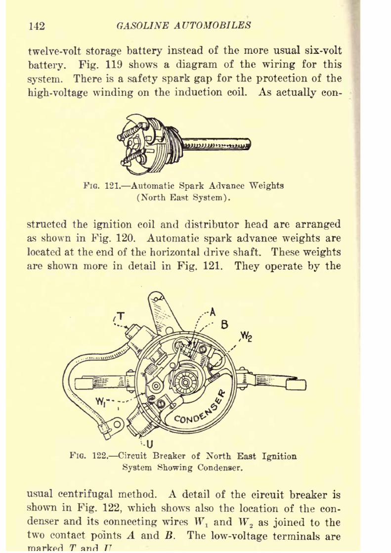
8/9/2019 (1921) Gasoline Automobiles
http://slidepdf.com/reader/full/1921-gasoline-automobiles 154/280
142 GASOLINE AUTOMOBILES
twelve-volt storage battery instead of the more usual six-volt
battery. Fig. 119 shows a diagram of the wiring for this
system. There is a safety spark gap for the protection of the
high-voltage winding on the induction coil. As actually con-
FIG. 121. Automatic Spark Advance Weights
(North East System).
structed the ignition coil and distributor head are arranged
as shown in Fig. 120. Automatic spark advance weights are
located at the end of the horizontal drive shaft. These weights
are shown more in detail in Fig. 121. They operate by the
FIG. 122. Circuit Breaker of North East Ignition
System Showing Condenser.
usual centrifugal method. A detail of the circuit breaker is
shown in Fig. 122, which shows also the location of the con-
denser and its connecting wires W\ and W2 as joined to the
two contact points A and B. The low-voltage terminals are
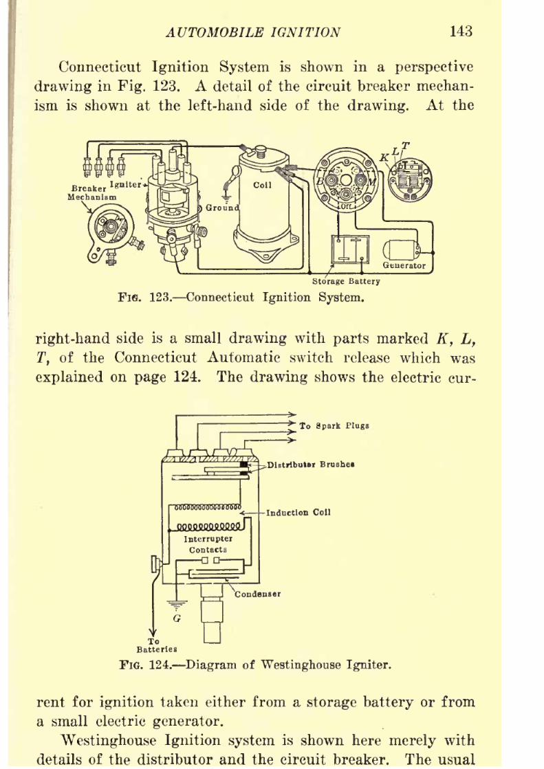
8/9/2019 (1921) Gasoline Automobiles
http://slidepdf.com/reader/full/1921-gasoline-automobiles 155/280
AUTOMOBILE IGNITION 143
Connecticut Ignition System is shown in a perspective
drawing in Fig. 123. A detail of the circuit breaker mechan-
ism is shown at the left-hand side of the drawing. At the
Storage Battery
FIG. 123. Connecticut Ignition System.
right-hand side is a small drawing with parts marked K, L,
T, of the Connecticut Automatic switch release which was
explained on page 124. The drawing shows the electric cur-
* To Spark Plugs
^Distributor Brushes
FIG. 124. Diagram of Westinghouse Igniter.
rent for ignition taken either from a storage battery or from
a small electric generator.
Westinghouse Ignition system is shown here merely with
details of the distributor and the circuit breaker. The usual
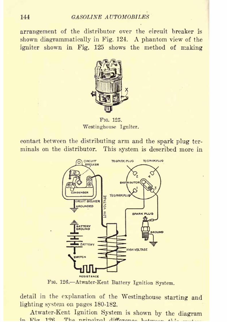
8/9/2019 (1921) Gasoline Automobiles
http://slidepdf.com/reader/full/1921-gasoline-automobiles 156/280
144 GASOLINE AUTOMOBILES
arrangement of the distributor over the circuit breaker is
shown diagrammatically in Fig. 124. A phantom view of the
igniter shownin
Fig.125 shows the
methodof
making
FIG. 125.
Westinghouse Igniter.
contact between the distributing arm and the spark plug ter-
minals on the distributor. This system is described more in
FIG. 126. Atwater-Kent Battery Ignition System.
detail in the explanation of the Westinghouse starting and
lighting system on pages 180-182.
Atwater-Kent Ignition System is shown by the diagram

8/9/2019 (1921) Gasoline Automobiles
http://slidepdf.com/reader/full/1921-gasoline-automobiles 157/280
AUTOMOBILE IGNITION 145
and most others is that the contact points of the circuit
breaker are together and touching only for an instant just
Fie. 127. Detail of Distributer Arm of
Atwater-Kent System.
FIG. 128. Detail of Attachment of High Voltage
Wires to Distributer Head.
Mechanism DryCt
FiQ. 129. Kemy Ignition System.
preceding the moment when the spark is to be made in one
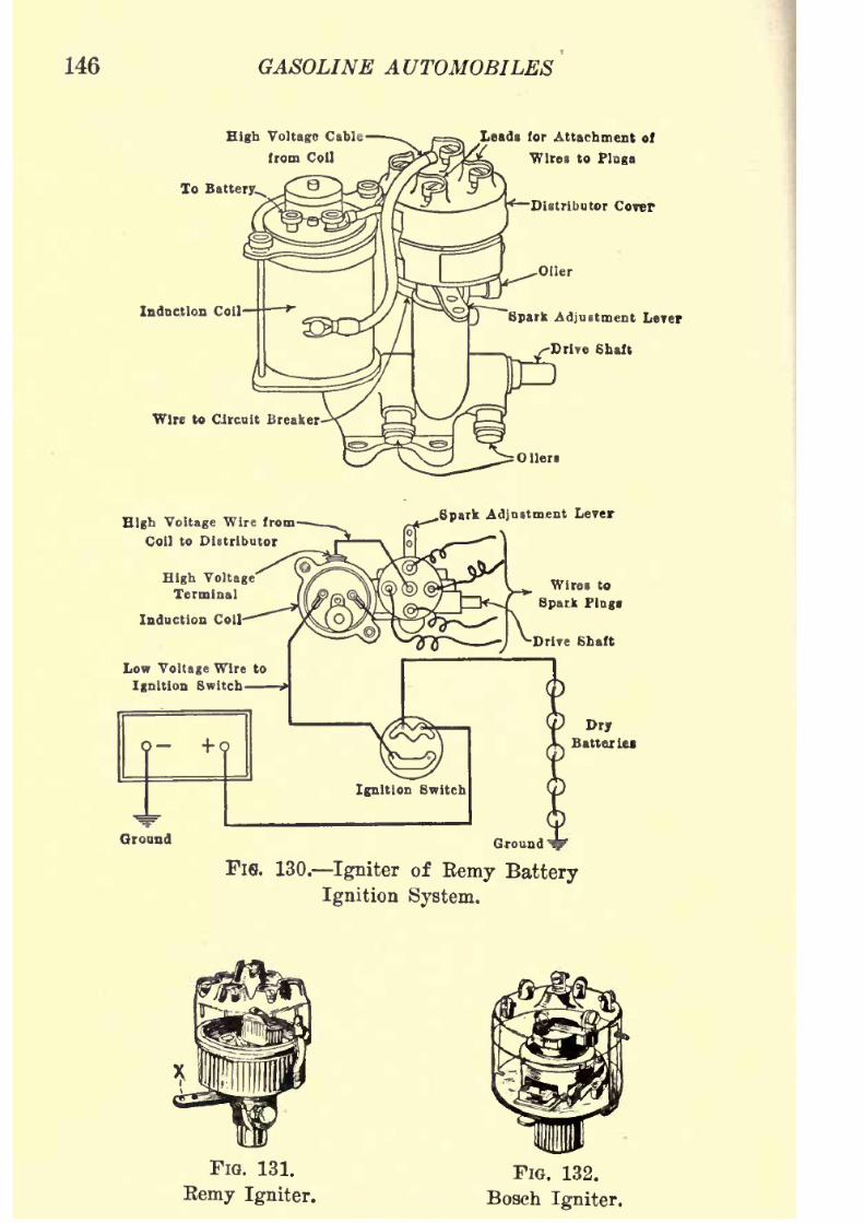
8/9/2019 (1921) Gasoline Automobiles
http://slidepdf.com/reader/full/1921-gasoline-automobiles 158/280
146 GASOLINE AUTOMOBILES
High Voltage Cable
from Coll
Leads for Attachment of
'Wires to Plugs
Distributor Cover
Spark Adjustment Lerer
Drive Shaft
Ground Ground 1
FlS. 130. Igniter of Kemy Battery
Ignition System.
FIG. 131.
Eemy Igniter.
FIG. 132.
Bosch Igniter.

8/9/2019 (1921) Gasoline Automobiles
http://slidepdf.com/reader/full/1921-gasoline-automobiles 159/280
AUTOMOBILE IGNITION 147
unnecessary to have a protective device to guard against over-
heating in case the ignition switch should be left closed when
the engine is not
running.
Details of the distributing arm
and method of attachment of the high-voltage wires to the
distributor terminals are shown in Figs. 127 and 128.
Remy Ignition System is shown clearly in Figs. 129 and
130. As shown in the latter figure the igniter (distributor
and circuit breaker) is mounted on a bracket which also sup-
ports the induction coil. Another view is shown in Fig. 131.
The igniter used in the new Bosch battery system is shown
in Fig. 132.
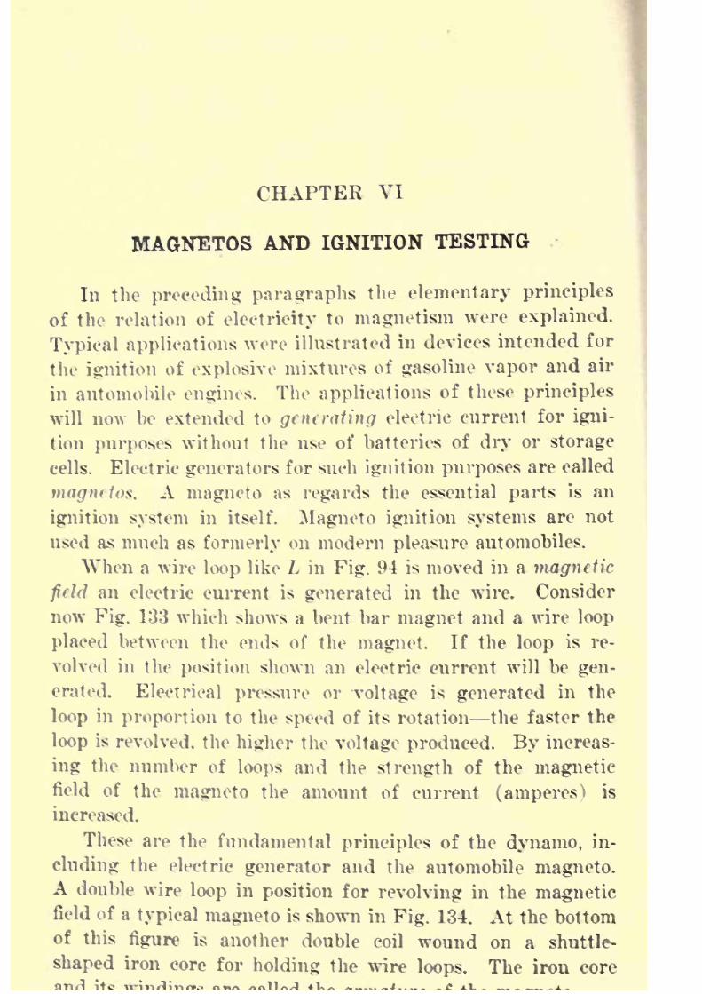
8/9/2019 (1921) Gasoline Automobiles
http://slidepdf.com/reader/full/1921-gasoline-automobiles 160/280
CHAPTER VI
MAGNETOS AND IGNITION TESTING
In the preceding paragraphs the elementary principles
of the relation of electricity to magnetism were explained.
Typical applications were illustrated in devices intended for
the ignition of explosive mixtures of gasoline vapor and air
in automobile engines. The applications of these principles
will now be extended to generating electric current for igni-
tion purposes without the use of batteries of dry or storage
cells. Electric generators for such ignition purposes arecalled
magnetos. A magneto as regards the essential parts is an
ignition system in itself. Magneto ignition systems are not
used as much as formerly on modern pleasure automobiles.
When a wire loop like L in Fig. 94 is moved in a magnetic
field an electric current is generated in the wire. Consider
now Fig. 133 which shows a bent bar magnet and a wire loop
placed between the ends of the magnet. If the loop is re-
volved in the position shown an electric current will be gen-
erated. Electrical pressure or voltage is generated in the
loop in proportion to the speed of its rotation the faster the
loop is revolved, the higher the voltage produced. By increas-
ing the number of loops and the strength of the magnetic
field of the magneto the amount of current (amperes) is
increased.
These are the fundamental principles of the dynamo, in-
cluding the electric generator and the automobile magneto.A double wire loop in position for revolving in the magneticfield of a typical magneto is shown in Fig. 134. At the bottom
of this figure is another double coil wound on a shuttle-
shaped iron core for holding the wire loops. The iron core
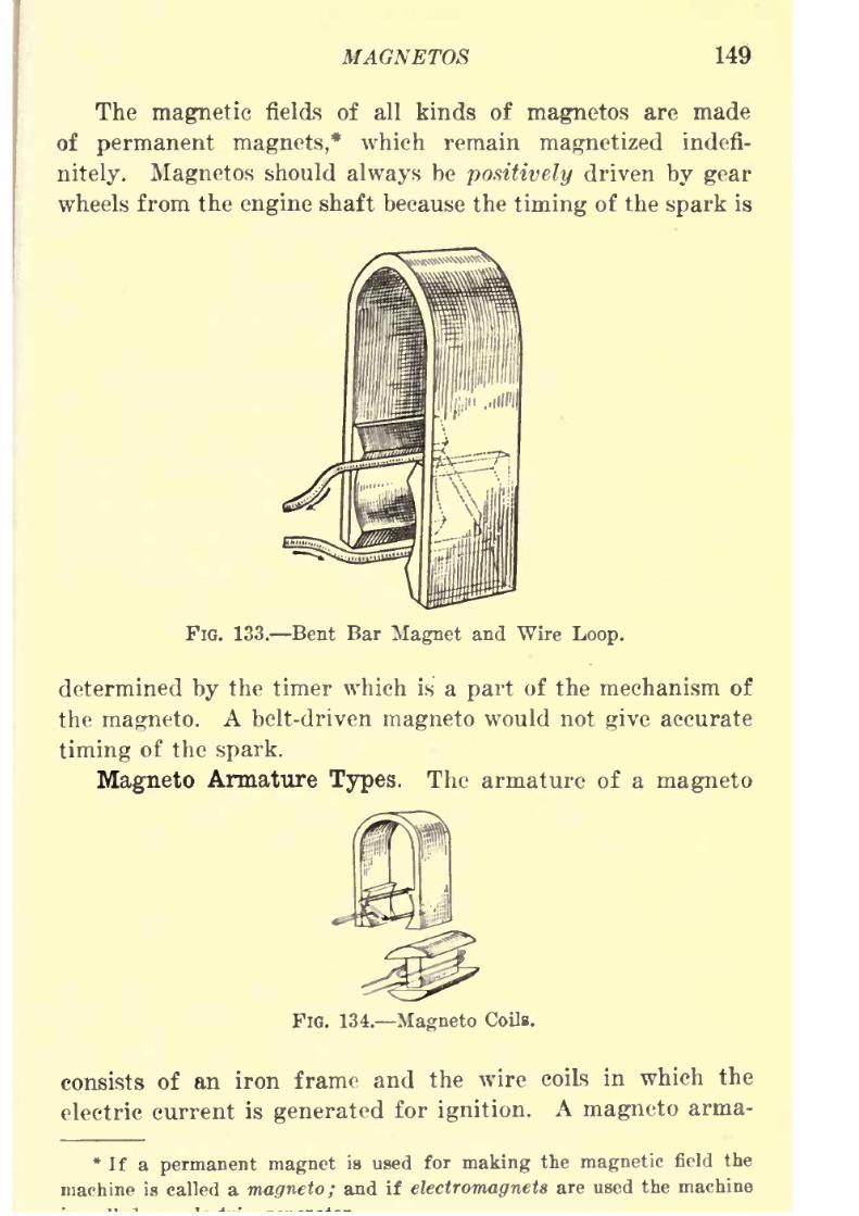
8/9/2019 (1921) Gasoline Automobiles
http://slidepdf.com/reader/full/1921-gasoline-automobiles 161/280
MAGNETOS 149
The magnetic fields of all kinds of magnetos are made
of permanent magnets,* which remain magnetized indefi-
nitely. Magnetos should always be positively driven by gear
wheels from the engine shaft because the timing of the spark is
FIG. 133. Bent Bar Magnet and Wire Loop.
determined by the timer which is a part of the mechanism of
the magneto. A belt-driven magneto would not give accurate
timing of the spark.
Magneto Armature Types. The armature of a magneto
FIG. 134. Magneto Coils.
consists of an iron frame and the wire coils in which the
electric current is generated for ignition. A magneto arma-
*If a permanent magnet is used for making the magnetic field the
machine is called a magneto; and if electromagnets are used the machine
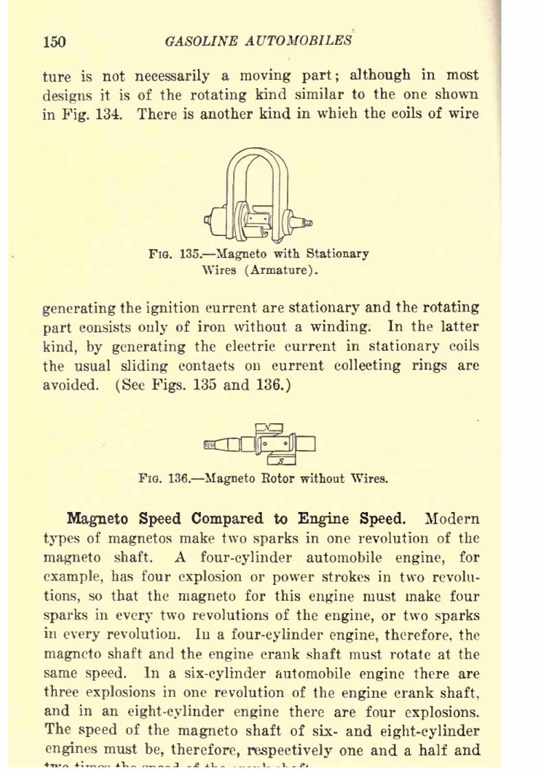
8/9/2019 (1921) Gasoline Automobiles
http://slidepdf.com/reader/full/1921-gasoline-automobiles 162/280
150 GASOLINE AUTOMOBILES
ture is not necessarily a moving part; although in most
designs it is of the rotating kind similar to the one shown
in Fig. 134. Thereis
another kindin which the coils of wire
FIG. 135. Magneto with Stationary
Wires (Armature).
generating the ignition current are stationary and the rotating
part consists only of iron without a winding. In the latter
kind, by generating the electric current in stationary coils
the usual sliding contacts on current collecting rings are
avoided. (See Figs. 135 and 136.)
FIG. 136. Magneto Rotor without Wires.
Magneto Speed Compared to Engine Speed. Modern
types of magnetos make two sparks in one revolution of the
magneto shaft. A four-cylinder automobile engine, for
example, has four explosion or power strokes in two revolu-
tions, so that the magneto for this engine must make four
sparks in every two revolutions of the engine, or two sparks
in every revolution. In a four-cylinder engine, therefore, the
magneto shaft and the engine crank shaft must rotate at the
same speed. In a six-cylinder automobile engine there are
three explosions in one revolution of the engine crank shaft,
and in an eight-cylinder engine there are four explosions.
Thespeed
of the
magnetoshaft of six- and
eight-cylinderengines must be, therefore, respectively one and a half and
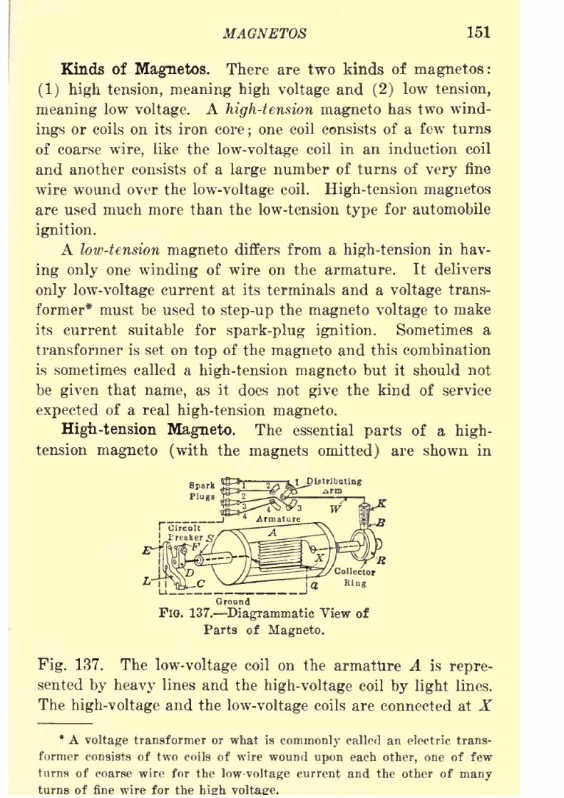
8/9/2019 (1921) Gasoline Automobiles
http://slidepdf.com/reader/full/1921-gasoline-automobiles 163/280
MAGNETOS 151
Kinds of Magnetos. There are two kinds of magnetos:
(1) high tension, meaning high voltage and (2) low tension,
meaning low voltage. A high-tension magneto has two wind-
ings or coils on its iron core;one coil consists of a few turns
of coarse wire, like the low-voltage coil in an induction coil
and another consists of a large number of turns of very fine
wire wound over the low-voltage coil. High-tension magnetos
are used much more than the low-tension type for automobile
ignition.
A low-tension magneto differs from a high-tension in hav-
ing only one winding of wire on the armature. It delivers
only low-voltage current at its terminals and a voltage trans-
former* must be used to step-up the magneto voltage to make
its current suitable for spark-plug ignition. Sometimes a
transformer is set on top of the magneto and this combination
is sometimes called a high-tension magneto but it should not
be given that name, as it does not give the kind of service
expected of a real high-tension magneto.
High-tension Magneto. The essential parts of a high-
tension magneto (with the magnets omitted) are shown in
Spark
Plugs
Ground
FIG. 137. Diagrammatic View of
Parts ofMagneto.
Fig. 137. The low-voltage coil on the armature A is repre-
sented by heavy lines and the high-voltage coil by light lines.
The high-voltage and the low-voltage coils are connected at X
* A voltage transformer or what is commonly called an electric trans-
former consists of two coils of wire woundupon
each other, one of few
turns of coarse wire for the low-voltage current and the other of manyturns of fine wire for the
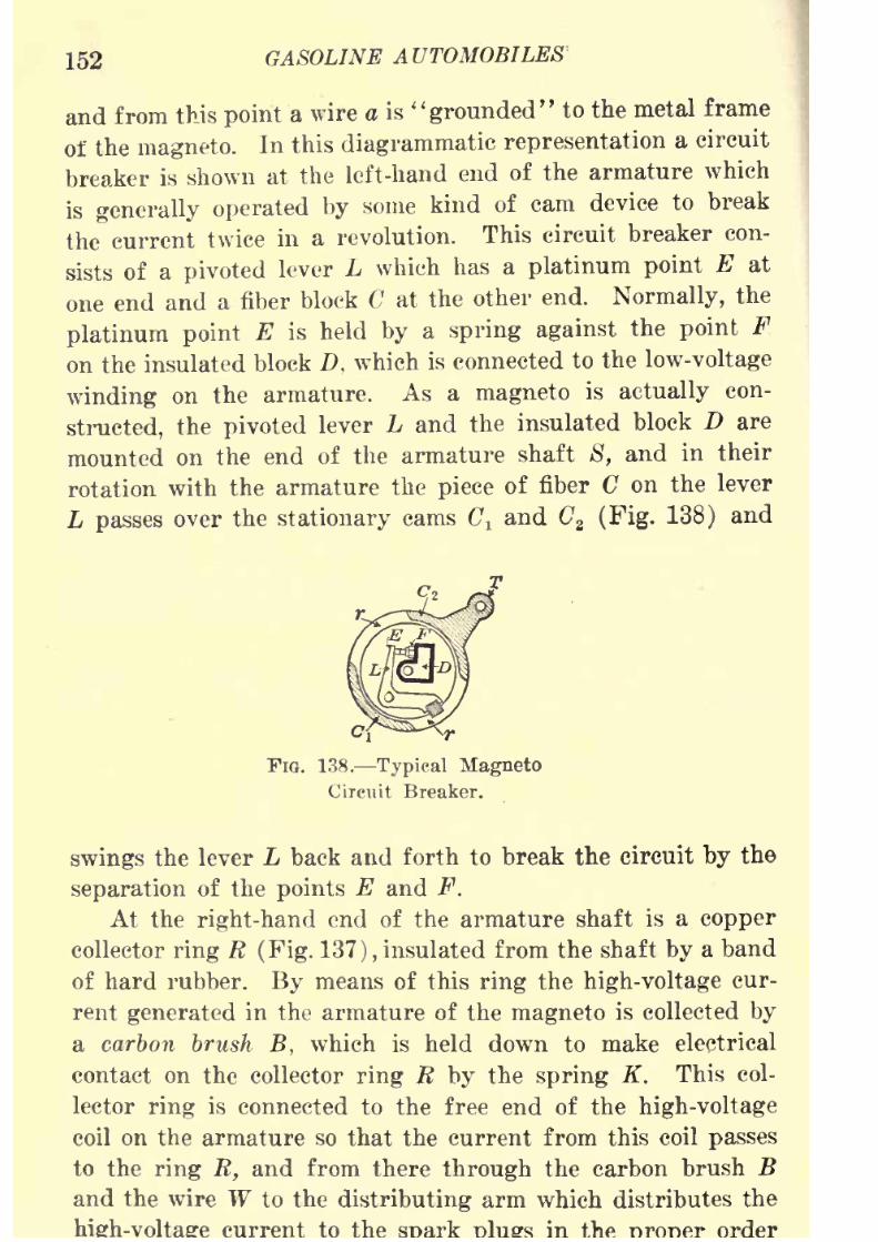
8/9/2019 (1921) Gasoline Automobiles
http://slidepdf.com/reader/full/1921-gasoline-automobiles 164/280
152 GASOLINE AUTOMOBILES
and from this point a wire a is "grounded" to the metal frame
of the magneto. In this diagrammatic representation a circuit
breaker is shown at the left-hand end of the armature which
is generally operated by some kind of cam device to break
the current twice in a revolution. This circuit breaker con-
sists of a pivoted lever L which has a platinum point E at
one end and a fiber block C at the other end. Normally, the
platinum point E is held by a spring against the point F
on the insulated block D, which is connected to the low-voltage
winding on the armature. As a magneto is actually con-
structed, the pivoted lever L and the insulated block D are
mounted on the end of the armature shaft 8, and in their
rotation with the armature the piece of fiber C on the lever
L passes over the stationary cams C t and Cz (Fig. 138) and
FIG. 138. Typical Magneto
Circuit Breaker.
swings the lever L back and forth to break the circuit by the
separation of the points E and F.
At the right-hand end of the armature shaft is a copper
collector ring R (Fig. 137), insulated from the shaft by a band
ofhard rubber. By means of
thisring the high-voltage
cur-
rent generated in the armature of the magneto is collected by
a carbon brush B, which is held down to make electrical
contact on the collector ring R by the spring K. This col-
lector ring is connected to the free end of the high-voltage
coil on the armature so that the current from this coil passes
to the ring R, and from there through the carbon brush B
and the wire W to the distributing arm which distributes the
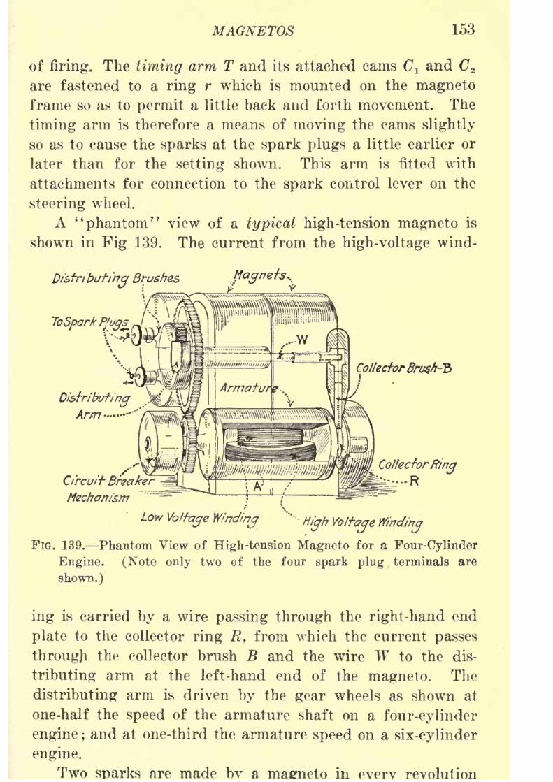
8/9/2019 (1921) Gasoline Automobiles
http://slidepdf.com/reader/full/1921-gasoline-automobiles 165/280
MAGNETOS 153
of firing. The timing arm T and its attached cams C^ and C 2
are fastened to a ring r which is mounted on the magneto
frame so as to permit a little back and forth movement. The
timing arm is therefore a means of moving the cams slightly
so as to cause the sparks at the spark plugs a little earlier or
later than for the setting shown. This arm is fitted with
attachments for connection to the spark control lever on the
steering wheel.
A "phantom" view of a typical high-tension magneto is
shown in Fig 139. The current from the high-voltage wind-
flagnets..
Co/lector Brush-"?)
CollectorRing
Rircuit Breaker
Mechanism
LowVoltage Winding
'"
High Voltage Winding
FIG. 139. Phantom View of High-tension Magneto for a Four-Cylinder
Engine. (Note only two of the four spark plug terminals are
shown.)
ingis carried
bya wire
passing throughthe
right-handend
plate to the collector ring R, from which the current passes
througji the collector brush B and the wire W to the dis-
tributing arm at the left-hand end of the magneto. The
distributing arm is driven by the gear wheels as shown at
one-half the speed of the armature shaft on a four-cylinder
engine ;and at one-third the armature speed on a six-cylinder
engine.
Two are made a in revolution

8/9/2019 (1921) Gasoline Automobiles
http://slidepdf.com/reader/full/1921-gasoline-automobiles 166/280
154 GASOLINE AUTOMOBILES
of this armature so that the armature of a magneto for a
four-cylinder engine must make two revolutions, causing four
sparks, in the same time that the distributor brush makes one
revolution. The gears are so arranged that when each of
the sparks is produced the distributing arm is resting on the
bar or segment connected to the proper spark plug.
A condenser for shortening the duration of the spark at
the contact points E and F (Fig. 137) in the low-voltage
circuit is mounted at the end of the armature shaft. As the
diagram in Fig. 137 is laid out, one terminal of the con-
denser would be connected at X and the other to the wire
Cotrfnct-Bngoker
FIG. 140. Magneto with Condenser on Armature Shaft.
shown dotted through the hollow shaft 8. Figs. 140 and 141
show the condenser as located in a magneto of a well-known
make.
A diagram of a high-tension magneto of the Bosch make for
a four-cylinder engine is shown in Fig. 142, with the impor-
tant parts marked with numbers which areexplained
in the
table below the figure. A somewhat simpler design is shown
in Fig. 143.
Safety Spark Gap. If by accident the wire connectingthe high-voltage coil of the armature to the collector ring R(Fig. 137) is broken or detached, the high-voltage current
will have no return path and may produce a voltage which
will damage the insulation of the high voltage coil on the
armature. Similar result from the excessive
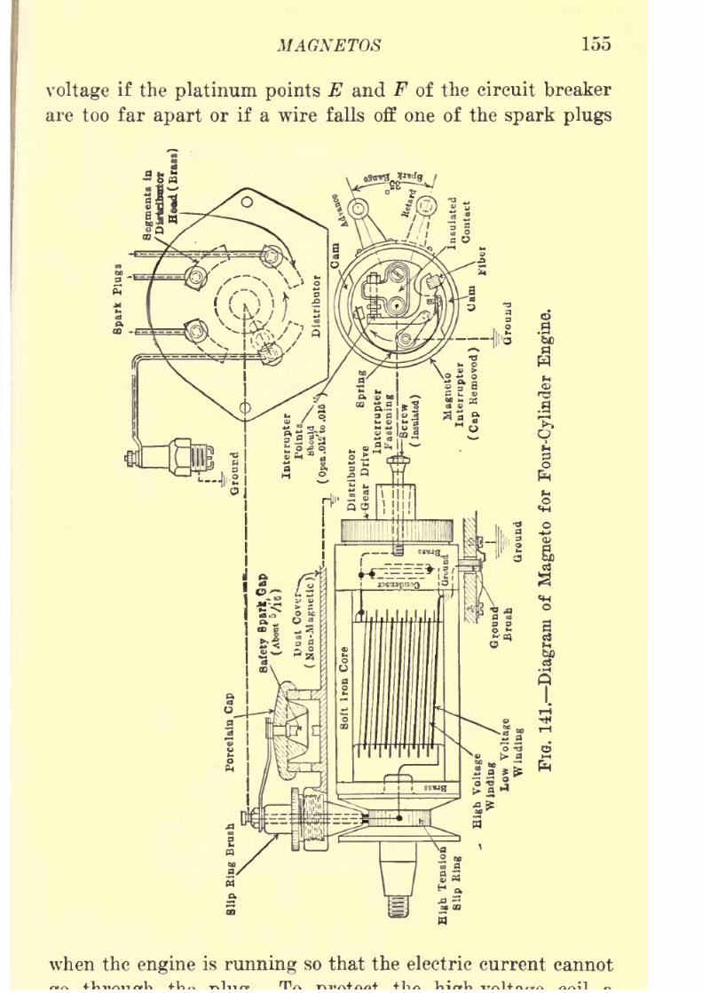
8/9/2019 (1921) Gasoline Automobiles
http://slidepdf.com/reader/full/1921-gasoline-automobiles 167/280
MAGNETOS 155
voltage if the platinum points E and F of the circuit breaker
are too far apart or if a wire falls off one of the spark plugs
when the engine is running so that the electric current cannot
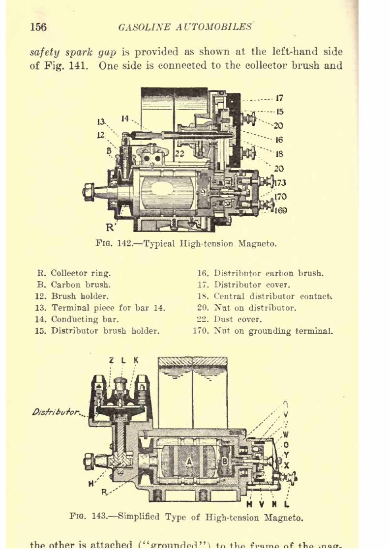
8/9/2019 (1921) Gasoline Automobiles
http://slidepdf.com/reader/full/1921-gasoline-automobiles 168/280
156 GASOLINE A UTOMOBILES
safety spark gap is provided as shown at the left-hand side
of Fig. 141. One side is connected to the collector brush and
FlG. 142. Typical High-tension Magneto.
E. Collector ring.
B. Carbon brush.
12. Brush holder.
13. Terminal piece for bar 14.
14. Conducting bar.
15. Distributor brush holder.
Z L K
16. Distributor carbon brush.
17. Distributor cover.
18. Central distributor contact-.
20. Nut on distributor.
22. Dust cover.
170. Nut on grounding terminal.
H V N L
FiO. 143. Simplified Type of High-tension Magneto,
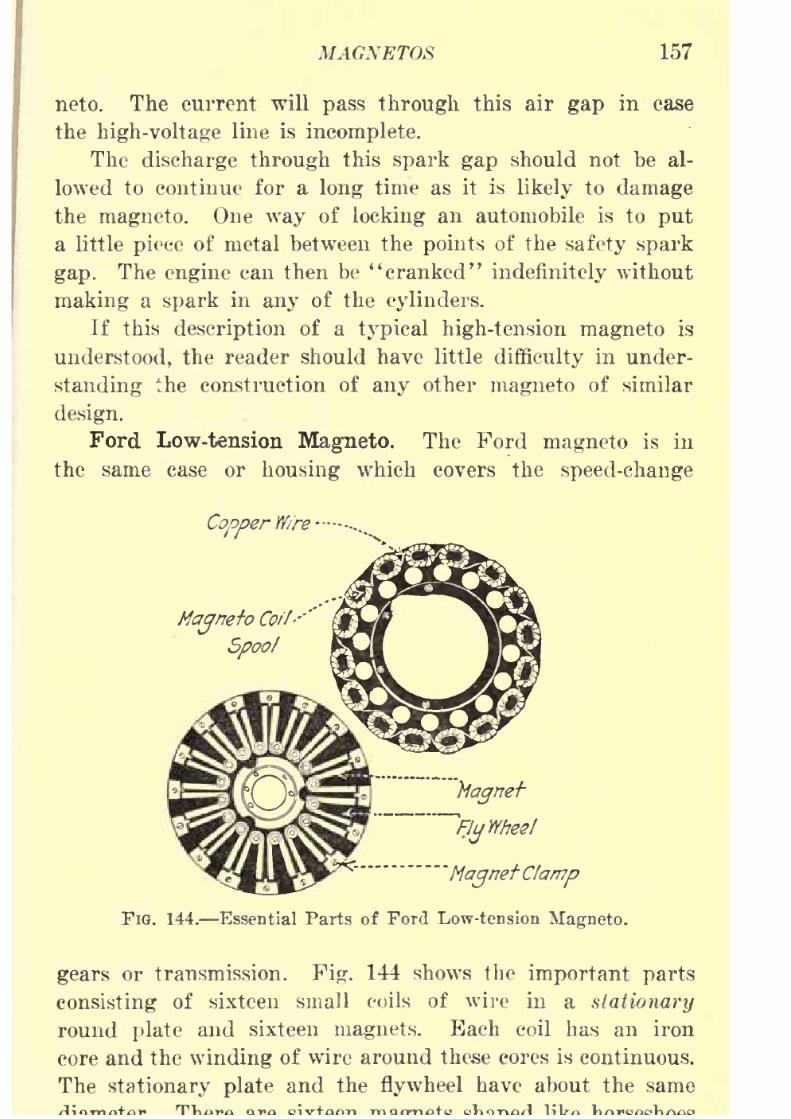
8/9/2019 (1921) Gasoline Automobiles
http://slidepdf.com/reader/full/1921-gasoline-automobiles 169/280
MAGNETOS 157
neto. The current will pass through this air gap in case
the high-voltage line is incomplete.
The discharge through this spark gap should not be al-
lowed to continue for a long time as it is likely to damage
the magneto. One way of locking an automobile is to put
a little piece of metal between the points of the safety spark
gap. The engine can then be "cranked" indefinitely without
making a spark in any of the cylinders.
If this description of a typical high-tension magneto is
understood, the reader should have little difficulty in under-
standing the construction of any other magneto of similar
design.
Ford Low-tension Magneto. The Ford magneto is in
the same case or housing which covers the speed-change
CopperWire-
MagnetoCoil--''
Spool
'MagnetClamp
FIG. 144. Essential Parts of Ford Low-tension Magneto.
gears or transmission. Fig. 144 shows the important parts
consisting of sixteen small coils of wire in a stationary
round plate and sixteen magnets. Each coil has an iron
core and the winding of wire around these cores is continuous.
The stationary plate and the flywheel have about the same

8/9/2019 (1921) Gasoline Automobiles
http://slidepdf.com/reader/full/1921-gasoline-automobiles 170/280
158 GASOLINE AUTOMOBILES
on the flywheel and the space between these magnets and the
coils on the stationary plate is only about a thirty-second
of an inch.The magnets on the flywheel set up a magnetic field
which when rotating in front of the coils on the stationary
'Flywheel Miynefc
FIG. 145. Ford Flywheel Magneto and
Vibrating Induction Coils.
plate generate an electric current in these coils. The magneto,
timer, and vibrator spark coils are shown diagrammatically
in Fig. 145. Fig. 146 is a drawing of a Ford engine showing
the flywheel magneto.
Graphiteshould not be
putin the oil used in a Ford
engine as it is likely to injure the coils. Sometimes the
magnets become demagnetized, causing weak ignition sparks.
In that case the magnets should be replaced with new ones.
A Ford magneto has only one winding which generates a
low-voltage current of about 18 volts, when the engine is
running at normal speed.
Dual and Double Ignition Systems. Since the amount
of current and voltage generated by a magneto depends
on its speed, it is obvious that at the low speed of starting,
especially of hand cranking, it is often difficult to get good
electric sparks in the engine cylinders for ignition. For this
reason some automobiles are provided with some other source
ofcurrent for start-ing. The auxiliary source is a battery
of dry cells or of storage cells. In the dual system of igni-'
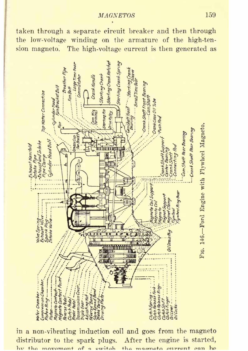
8/9/2019 (1921) Gasoline Automobiles
http://slidepdf.com/reader/full/1921-gasoline-automobiles 171/280
MAGNETOS 159
taken through a separate circuit breaker and then through
the low-voltage winding on the armature of the high-ten-
sion magneto. The high-voltage current is then generated as
in a non-vibrating induction coil and goes from the magneto
distributor to the spark plugs. After the engine is started,
8/9/2019 (1921) Gasoline Automobiles
http://slidepdf.com/reader/full/1921-gasoline-automobiles 172/280
160 GASOLINE AUTOMOBILES
used for engine ignition in the ordinary way. Some induction
coils are provided with a ratchet device on the dash board
which makes a "shower" of sparks for starting by rapidly
making and breaking the ignition circuit.
In the double system of ignition the engine has two spark
plugs in each cylinder, one of which gets current from a
battery and induction coils and the other from the magneto.
In this system there are really two separate ignition outfits,
and the engine can be operated on either one or both at any
time.
Care of Magnetos. If any moisture gets on the high-
voltage coil of a magneto it may cause a short circuit so
that the high-voltage current will not go to the spark plugs
but will go through the insulation of the coil and conse-
quently the engine will be stopped.
The bearings on each end of the magneto shaft should
occasionally have a few drops of oil. But this is one part
of an automobile that should not be oiled too much. As
regards any other part of an automobile it is best to give
too much oil rather than too little. A magneto should be
kept clean and dry. Repairing a magneto is work for an
expert electrical mechanic and should not be attempted by
amateurs.
Magneto Adjustments. Timing. If a magneto is out of
adjustment, the engine should be cranked until "No. 1"
cylinder (the one nearest the radiator) is in the position
of firing the explosive mixture. This is usually just a little
past the dead center (top of stroke) if the spark is set
for the usual starting position (not advanced). Nextdetermine which one of the distributor points is wired to
"No. 1" cylinder. Then rotate the armature of the magnetountil the distributing arm comes into contact with the
distributing points for "No. 1" cylinder,, and adjust these
relative positions so that the contact points are released from
each other when the
distributing ringis
in the position ofa fully retarded spark. In this position the magneto should

8/9/2019 (1921) Gasoline Automobiles
http://slidepdf.com/reader/full/1921-gasoline-automobiles 173/280
MAGNETOS 161
trol rod going to the steering wheel should then be con-
nected and adjusted so that the contact points just open
when the spark lever on the steering wheel is fully retarded.
This position of the lever permits advancing the ignition
spark the maximum amount. The circuit breaker points
of a magneto are opened about one-sixty-fourth of an inch,
while on a battery system they are usually opened about twice
as much. A gage is usually furnished for setting the circuit
breaker points of a magneto. The carbon brushes of the
distributor will collect dust and should be occasionally cleaned
with a piece of clean cloth.
Demagnetized Magnets. If the magnets are weak the
sparks will be weak. The spark depends not only on the
strength of the magnets but also on the speed of the engine.
Increased engine speed gives better ignition current from
a
magnetowith weak
magnets.If an engine stalls easily when driving through crowded
city streets and seems to have little power at slow speeds
it is likely that the magnets are weak and the ignition
current is of very low voltage. The magnets can be remag-
netized in a very short time and without much expense.
Magneto vs. Battery. A magneto gives a very hot spark
at high speed. Magnetos are used more on trucks than on
automobiles. Most modern automobiles have an electric self-
starter and a storage battery system, so arranged that one can
get into the seat and start without cranking the engine. A
battery ignition system gives a hotter spark at low speed than
a magneto system. But when running at high speed a mag-
neto may give a hotter spark than a battery.
There is much advertising of the merits of one of these
systems of ignition over the other. The double system of
ignition shows both methods under the same conditions.
Careful experiments show that there is practically no differ-
ence as to the effectiveness of the two methods of ignition.
Testing Spark Plugs. When a spark plug has been taken
out for cleaning, it should be screwed back again into the

8/9/2019 (1921) Gasoline Automobiles
http://slidepdf.com/reader/full/1921-gasoline-automobiles 174/280
162 GASOLINE AUTOMOBILES
pressure by leakage and it should be put back carefully
to avoid changing of the air gap distance or breaking the
porcelain. It is a good precaution to take out the spark
plugs and clean them before going on a long trip. If, after
cleaning a spark plug, the ignition in the cylinder in which
it belongs is still not as it should be, the spark plug should
be put into another cylinder and if there is then difficulty
with the ignition in that cylinder, it may be assumed the
spark plugis defective.
The easiest way to tell whether any of the cylinders
of an engine are not working is to test each of the spark
plugs by putting the end of a screw-driver with a wooden
handle on the casting or frame of the engine and touching
the side of its steel blade on the metal top of the spark
plug. The current will then go from the top of the spark
plug through the screw-driver to the metal of the engine
cylinder, instead of going down through the spark plug and
across its air gap. While the screw-driver is in this position
there is no spark at the spark plug. If the engine changes
its speed, when each spark plug is tested, the ignition is
satisfactory. On the other hand, if the speed of the engine
does not change when the screw-driver is put on one ofthe spark plugs,, there is a good indication that the ignition
is defective. It is very difficult, however, to test six-, eight-,
or twelve-cylinder engines by this method, as it is difficult
to hear a momentary change of speed in an engine with a
large number of cylinders.
The same voltage that will make an ignition spark jumpone thirty-second of an inch across the air gap of a spark
plug inside an automobile engine cylinder will make the
spark jump at least a quarter of an inch outside the cylinder.
The difference is due to the greater resistance of the air
gap of the spark plug to the passage of the spark when it
must go through a compressed explosive mixture. If, there-
fore, the spark jumps across one-quarter of an inch outside
the engine cylinders, it is likely the ignition current is giving

8/9/2019 (1921) Gasoline Automobiles
http://slidepdf.com/reader/full/1921-gasoline-automobiles 175/280
MAGNETOS 163
rent is going through a crack in the porcelain of the spark
plug.
One of the best tests of a spark plug is to take off the
wire carrying the ignition current and hold it a quarter
inch away from the top of the spark plug. If there is a
spark jumping across this air gap at the top of the plug
it is not likely the trouble is with the spark plug. In making
this test care should be taken that the current is not stopped
fromgoing through
thespark plug,
as
stoppingthe
highvoltage current may burn out the fine wire winding of the
induction coil. Moreover, if the tester gets his fingers on
bare connections or on uninsulated wires when making this
test, he is likely to have an unpleasant "shock."
If the engine misses explosions on a hill, and runs satis-
factorily on the level, there is probably some trouble with
the ignition in the spark plug. Sometimes it is difficult to
find the troublesome cylinder especially if it stops missing
explosions at the top of the hill. If the missing occurs with
regularity it is likely the air gap of one of the spark plugs
is larger than it should be. If one of the air gaps is too
wide, the points should be pressed together to the proper
distance.
Correct Length of Spark Plugs. It is not advisable to
buy all kinds of spark plugs recommended by stores. Some
spark plugs picked up at random will project too far into
the cylinders of some engines so that the wires or "points"
at the air gap of the spark plug get red hot and may ignite
the explosive mixture too soon. There is often the same
difficulty with spark plugs which have very thin wires or
"points" at the air gap. On the other hand, if a spark
plug is too short the air gap wires cannot enter the com-
bustion space and are in "dead gas." It is best to use the
kind of spark plug that goes with the engine. Cheap spark
plugs are dear at any price, as the high-voltage current is
likely to go through the porcelain.
Care of Distributor. If an is after
8/9/2019 (1921) Gasoline Automobiles
http://slidepdf.com/reader/full/1921-gasoline-automobiles 176/280
164 GASOLINE AUTOMOBILES
the distributor should be examined. The cover can be taken
off and held up so that it can be wiped off inside. Some-
times there is a thin coating of dirt or of oxide on the
contact or other parts and the ignition current does not
go through them at all or does not go to the right points.
Because of such a coating on the distributor points, the
current, in taking the easier path, may jump five or six
times as far, rather than go to the right points. Under these
unfavorable conditions thecylinder
which is
skippingex-
plosions will be the one which is on its compression stroke at
the moment so that its spark plug is in highly compressed
explosive mixture, and the spark goes over the coating of
dirt to the distributor point of the spark plug of a cylinder
which is not on the compression stroke. For cleaning the
distributor, it is not necessary to remove the wires.
Nearly all automobiles except the Ford make have a
distributor, and in this automobile the timer must be in-
spected and cleaned in very much the same way for the
same reasons.
Preignition. When any small piece of metal or a bit
of carbon deposit in an engine cylinder becomes red hot,
it will ignite the explosive mixture at the moment of contactwithout an ignition spark. Such "automatic" ignition
generally takes place long before the spark is made by the
ignition device, and thus causes a considerable loss of power.
This early ignition of the mixture is called preignition.
Recent investigations show that overheated valves and bits
of carbon scarcely ever cause preignition but that it is fre-
quently caused by' overheated "points" at the air gap of
spark plugs. Preignition is simply tested by cutting off the
ignition current at the switch and observing whether the
engine continues to ignite the charge for a moment in one
or more cylinders. If the engine has a cut-out on the muffler,
its use will assist in this test.
Knocking and Related Trouble. It will be noticed some-
times that an engine makes unpleasant noises called knock-
8/9/2019 (1921) Gasoline Automobiles
http://slidepdf.com/reader/full/1921-gasoline-automobiles 177/280
MAGNETOS 165
example, the throttle valve of the carbureter is opened wider
than in ordinary operation so that the engine takes an un-
usually large amount of explosive mixture. As a result
there is higher compression in all the cylinders, which causes
exceedingly rapid combustion. In other words, because of
the higher compression, there is quicker combustion of the
explosive mixture in the cylinders. This unpleasant noise
can be avoided if the spark lever is set back a little (retarded
spark) so that the ignition will be started a little later in the
cylinders.
Number of Spark Plugs. Two spark plugs in each engine
cylinder insure more rapid ignition and increase the power
of the engine for the same amount of gasoline used. Obvi-
ously, the advantage of two spark plugs is greatest in
cylinders of large diameter. In a test of an engine with
cylinderswhich were five and one-half inches in
diameter,four per cent more power was developed with two spark
plugs than with a single spark plug. Engines of smaller
diameter would similarly give more power with two spark
plugs but the percentage increase would be less. Using four
spark plugs instead of one in a single large engine cylinder
will increase the power more than ten per cent without increas-
ing the amount of gasoline used.
Reasons for Spark Advance. It takes some time for the
combustible mixture to be completely ignited, and obviously
ignition should be complete, when the piston in an automobile
engine cylinder begins its explosion or power stroke.* When
starting an engine, even with a self-starter, the piston moves so
slowly that if the explosive mixture is ignited before the
piston gets to the top of its stroke the engine may start
backward. If an engine is being started by hand cranking,
it is not unusual for the quick, reverse movement of the
* The result is that during all the time required for ignition, the
pressure is building up rapidly in the cylinder and is causing a back-
ward pressure on the piston which is not useful as "compression"pressure. Journal of Society of Automotive Engineers, November, 1920,
8/9/2019 (1921) Gasoline Automobiles
http://slidepdf.com/reader/full/1921-gasoline-automobiles 178/280
166 GASOLINE AUTOMOBILES
starting crank to break an arm or a collar bone of the person
using it. It takes a fraction of a second after the mixture
is ignited before there is an explosion. The ignition sparkmust, therefore, be set to occur at a different piston position
for starting than for regular operation. When an engine
is at normal speed and the piston is moving rapidly it is
necessary to start the combustion of the explosive mixture
earlier than when the engine is being started. This early
ignition is called the spark advance.
After the engine has been started and is gaining speed
the spark control lever on the steering wheel should be
gradually advanced till it is in the position for usual running
conditions. It should not be advanced so far that the pistons
make a thumping or "pounding" noise in the cylinders.
The amount of the advance of ignition depends on the three
following conditions in the engine cylinders:
(1) If the combustible mixture is ignited on all sides
and in the center simultaneously it will cause
the charge to burn more rapidly just as when,
in burning a pile of brush, it burns faster if the
torch is applied on all sides instead of at one
point only.One
wayto
accomplishthis is to use
more than one spark-plug per cylinder.
(2) If the combustible mixture were agitated within the
cylinder or rotated fast enough so that most of
it passed the spark while the crank moved only
a little, the effect would be the same as if the
spark-plug ran around the edge of the cylinder
igniting the gas on all sides almost simultane-
ously.
(3) If higher compression pressures were used, the
flame would travel through the charge muchfaster and would at the same time, make possible
the use of smaller combustion-chambers. This
means that the flame would not be required totravel so far. The objection to using high com-

8/9/2019 (1921) Gasoline Automobiles
http://slidepdf.com/reader/full/1921-gasoline-automobiles 179/280
CHAPTER VII
ELECTRIC STARTERS
Starters in General. Although a modern gasoline engine
for automobile or aeroplane services is a marvel of
mechanical ingenuity furnishing power with less weight
than any other kind of engine, it cannot, with all its wonder-
ful improvements, start on its own power like other kinds
of engines and motors. This is because there is only one
power stroke to three idle strokes. Once it is started, how-
ever,the
powerfor these three "waste" strokes is
suppliedby a rapidly rotating flywheel. For starting, external power
is needed, which may be human power as applied in "wind-
ing" the engine crank or "stored" power as used in a start-
ing motor.
As automobiles are now equipped, nearly all the starting
motors (called "self-starters") are of the electrical kind.
Few mechanical starters are now used.
Electric Starters. The three essential parts of an electric
starter are (1) an electric motor, attached either directly to
the flywheel or by intermediate gears to the crank shaft of
the engine, to give the "cranking power"; (2) an electric
storage battery of sufficient current capacity to drive the elec-
tric motor for starting; (3) an electric generator connected
by gearing or otherwise to the crank shaft of the engine
to generate the electric current for charging the storage bat-
tery. For simplicity of statement, it will be assumed that
the current for electric lights and for cylinder ignition
is also always taken from the storage battery. In some elec-
tric starting systems, the electric motor and the generator are
combined as will be explained later. This combination is

8/9/2019 (1921) Gasoline Automobiles
http://slidepdf.com/reader/full/1921-gasoline-automobiles 180/280
168 GASOLINE AUTOMOBILES
The electric storage battery and the electric generator
are not very different in construction from the usual com-
mercial types.The
principles underlying
the operation of
storage batteries have been explained (see page 107), and the
general principles of electrical design of electric generators
have been explained in the Chapter 011 Magnetos (see page
148). A generator differs in essential parts from a magneto
only in having electro-magnets instead of permanent magnets.
Permanent magnets are made of specially hardened steel and
on being magnetized retain their magnetism without much
diminution for many year's. A generator resembling a mag-
neto would not be satisfactory for charging a storage
battery as the amount of current it could give would be too
small for practical use. Electro-magnets which are much
stronger than permanent magnets can be made by passing a
current of electricity through a coil of wire surrounding the
magnet. By the use of electro-magnets, electric generators of
any desired capacity can be made. A coil of wire on an iron
spool, if rotated by connection to the shaft of an automobile
engine in a magnetic field, will have electric current gen-
erated in it just as in a magneto. The current developed in
a magneto or any electric generator is, however, an alternating
current, which cannot be used for charging a storage battery.
In order to use electric current for storage battery service it
must come from an electric machine as direct current. The
device or attachment of a generator for changing the alter-
nating to direct current is called a commutator. It consists
of short copper bars which are insulated from each other, and
each two bars diametrically opposite, are connected by a wire
loop wound over the armature. As actually constructed, the
commutator and armature coils are attached to the shaft and
firmly bound together. Carbon brushes bear on the curved
surface of the commutator to "gather" the electric current
in the armature and carry it to the terminals of the storage
battery, the lights, the induction coils, etc. Connected to themain wires, carrying the electric current from the armature,
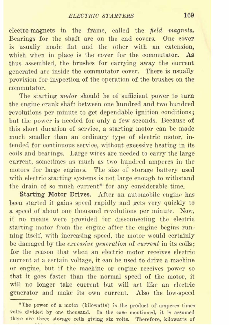
8/9/2019 (1921) Gasoline Automobiles
http://slidepdf.com/reader/full/1921-gasoline-automobiles 181/280
ELECTRIC STARTERS 169
electro-magnets in the frame, called the field magnets.
Bearings for the shaft are on the end covers. One cover
is
usually
made flat and the other with an extension,
which when in place is the cover for the commutator. As
thus assembled, the brushes for carrying away the current
generated are inside the commutator cover. There is usually
provision for inspection of the operation of the brushes on the
commutator.
The starting motor should be of sufficient power to turn
the engine crank shaft between one hundred and two hundred
revolutions per minute to get dependable ignition conditions;
but the power is needed for only a few seconds. Because of
this short duration of service, a starting motor can be made
much smaller than an ordinary type of electric motor, in-
tended for continuous service, without excessive heating in its
coils and bearings. Large wires are needed to carry the large
current, sometimes as much as two hundred amperes in the
motors for large engines. The size of storage battery used
with electric starting systems is not large enough to withstand
the drain of so much current* for any considerable time.
Starting1 Motor Drives. After an automobile engine has
been started it gains speed rapidly and gets very quickly to
a speed of about one thousand revolutions per minute. Now,
if no means were provided for disconnecting the electric
starting motor from the engine after the engine begins run-
ning itself, with increasing speed, the motor would certainly
be damaged by the excessive generation of current in its coils;
for the reason that when an electric motor receives electric
current at a certain voltage, it can be used to drive a machine
or engine, but if the machine or engine receives power so
that it goes faster than the normal speed of the motor, it
will no longer take current but will act like an electric
generator and make its own current. Also the low-speed
*The power of a motor (kilowatts) is the product of amperes times
volts divided by one thousand. In the case mentioned, it is assumedthere are three storage cells giving six volts. Therefore, kilowatts of
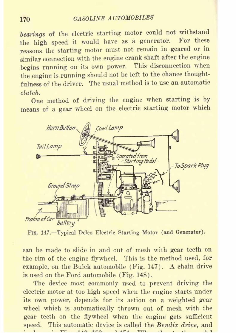
8/9/2019 (1921) Gasoline Automobiles
http://slidepdf.com/reader/full/1921-gasoline-automobiles 182/280
170 GASOLINE AUTOMOBILES
bearings of the electric starting motor could not withstand
the high speed it would have as a generator. For these
reasons the starting motor must not remainin
gearedor in
similar connection with the engine crank shaft after the engine
begins running on its own power. This disconnection when
the engine is running should not be left to the chance thought-
fulness of the driver. The usual method is to use an automatic
clutch.
One method of driving the engine when starting is by
means of a gear wheel on the electric starting motor which
Fie. 147. Typical Delco Electric Starting Motor (and Generator).
can be made to slide in and out of mesh with gear teeth on
the rim of the engine flywheel. This is the method used, for
example, on the Buick automobile (Fig. 147). A chain drive
is used on the Ford automobile (Fig. 148).
The device most commonly used to prevent driving the
electric motor at too high speed when the engine starts under
its own power, depends for its action on a weighted gear
wheel which is automatically thrown out of mesh with the
gear teeth on the flywheel when the engine getssufficient
speed. This automatic device is called the Bendix drive, and
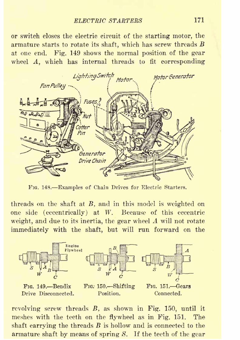
8/9/2019 (1921) Gasoline Automobiles
http://slidepdf.com/reader/full/1921-gasoline-automobiles 183/280
ELECTRIC STARTERS 171
or switch closes the electric circuit of the starting motor, the
armature starts to rotate its shaft, which has screw threads B
at one end. Fig. 149 shows the normal position of the gear
wheel A, which has internal threads to fit corresponding
MotorGenerator
FIG. 148. Examples of Chain Drives for Electric Starters.
threads on the shaft at B, and in this model is weighted on
one side (eccentrically) at W. Because of this eccentric
weight, and due to its inertia, the gear wheel A will not rotate
immediately with the shaft, but will run forward on the
FIG. 149. Bendix
Drive Disconnected.
FIG.- 150 Shifting
Position.
FIG. 151. Gears
Connected.
revolving screw threads B, as shown in Fig. 150, until it
meshes with the teeth on the flywheel as in Fig. 151. The
shaft carrying the threads B is hollow and is connected to the
armature shaft by means of spring S. If the teeth of the gear

8/9/2019 (1921) Gasoline Automobiles
http://slidepdf.com/reader/full/1921-gasoline-automobiles 184/280
172 GASOLINE AUTOMOBILES
come together, the spring S will allow the gear wheel to
revolve until the teeth do mesh. When the gear wheel is
meshed with the flywheel as in Fig. 151 the spring Swill
betightly compressed and the power of the electric motor
becomes effective for turning the engine.
The spring S acts like a cushion when turning the engine
over against compression, or if the engine backfires. As soon
as the speed of the engine is higher than that of the starting
motor the flywheel will drive the gear wheel A at a higher
speed than that of the armature shaft of the starting motor,
so that the gear wheel will be turned in the opposite direction
on its screw thread and be automatically released from the
teeth on the flywheel. The starting switch must be released
as soon as the engine starts on its own power. If this is not
done the starting motor shaft will increase in speed also and
the gear A will not disengage. This device thus prevents the
engine from driving the starting motor.
"When the starting motor drives the engine by means of a
silent chain or similar method (see Fig. 148) as used on
Ford, Dodge, and Franklin automobiles, for example, the
engine is prevented from driving the motor by the use of an
over-running clutch, which slips when the engine tends todrive the motor.
A typical construction of an over-running clutch, shown
in Fig. 152, consists of a star-shaped inner member, which is
FIG. 152. Overrunning Clutch.
keyed to the shaft, free to rotate inside the intermediate gear.
Four rollers R are inserted between these two members in such
a way that they will bind in the angles of the star when theshaft is turned in one direction, but will rest free from tho
8/9/2019 (1921) Gasoline Automobiles
http://slidepdf.com/reader/full/1921-gasoline-automobiles 185/280
ELECTRIC STARTERS 173
There is also another type of starting . motor drive which
depends for its action on the magnetic pull of the strong
electromagnets attached to the motor to draw the entire
armature and the gear wheel at the end of its shaft into a
position where the gear wheel meshes with teeth on the fly-
wheel. In this device the armature is mounted on a hollow
shaft which has a slot in the middle into which is fitted a
projection on the inside of the hub of a small gear wheel. A
shifting rod inside the hollow shaft and fastened to the
projection on the hub of the gear wheel, is attached at one
end to a large piece of soft iron which fits inside a coil of
wire. When the current from the storage battery goes
through the coil the piece of soft iron is pulled into the coil
and draws with it the shifting rod and the attached gear
wheel, so that it is brought into mesh with the teeth on the
flywheel. All starting motors require a large current at the
moment they start to revolve; and since this large current
flows also through the coil of the shifting magnet, it gives
sufficient magnetic pull to overcome the tension of a spiral
spring on the shaft intended to oppose this motion. As soon
as the teeth 011 the gear wheel mesh with the teeth on the
flywheel the current required to turn the engine is large
enough in the electromagnet to hold the gear wheel in mesh
against the tension of the spring. But as soon as the engine
runs on its own power, the current needed for the starting
motor is very small and the coil of the electromagnet is
weakened, so that the spring is stronger than the magnetic
pull and the gear wheel is drawn out of contact with the fly-
wheel.
Starting Motor Switch. The Delco starting motor switch
is shown by Fig. 153. It is installed on the floor boards of
the automobile and is operated by the driver's foot. By
pressing the foot button a connection is made between the
battery lead and the starting motor lead. The leads are heavycopper cables, usually No. or No. 00 size, made of stranded
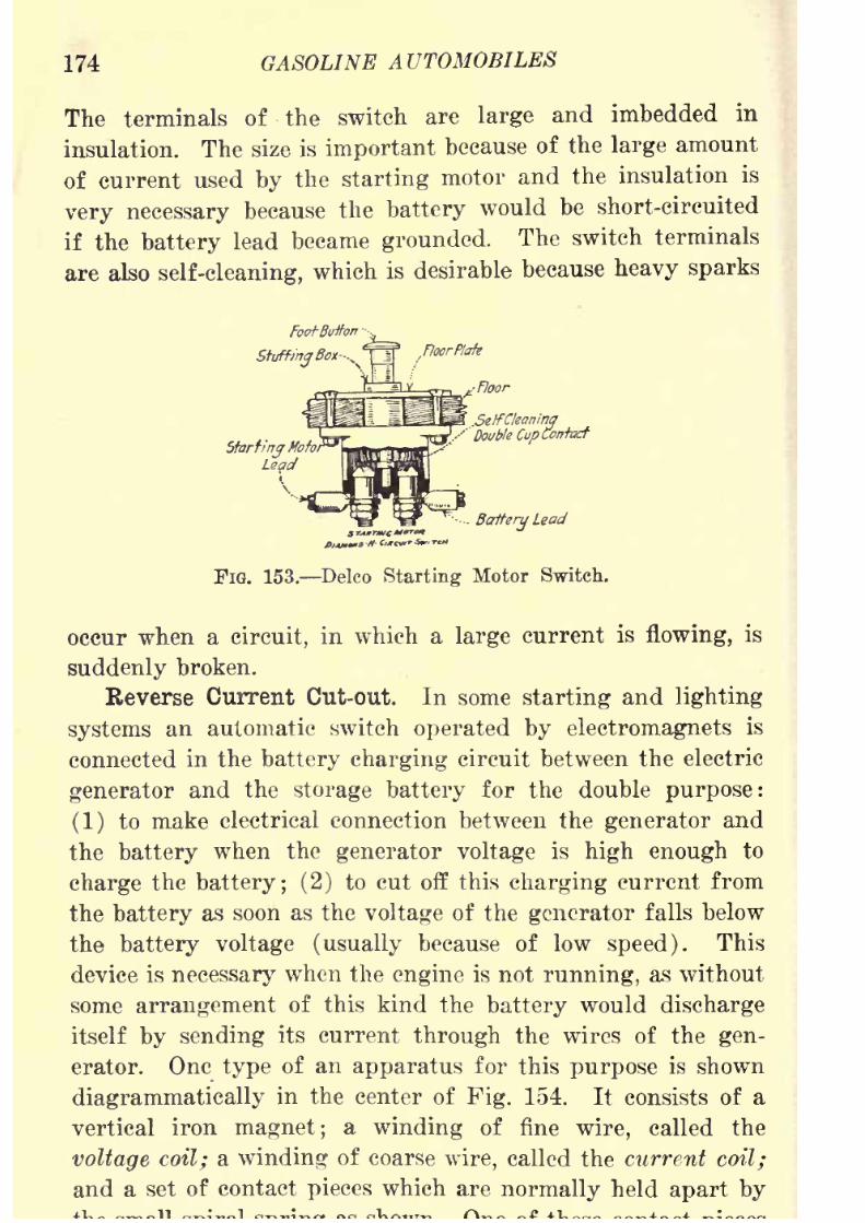
8/9/2019 (1921) Gasoline Automobiles
http://slidepdf.com/reader/full/1921-gasoline-automobiles 186/280
174 GASOLINE AUTOMOBILES
The terminals of the switch are large and imbedded in
insulation. The size is important because of the large amount
ofcurrent
usedby
thestarting
motor and the insulation is
very necessary because the battery would be short-circuited
if the battery lead became grounded. The switch terminals
are also self-cleaning, which is desirable because heavy sparks
SetfCkam'ngDouble Cup Contact
BatteryLead
FIG. 153. Delco Starting Motor Switch.
occur when a circuit, in which a large current is flowing, is
suddenly broken.
Reverse Current Cut-out. In some starting and lighting
systems an automatic switch operated by electromagnets is
connected in the battery charging circuit between the electric
generator and the storage battery for the double purpose:
(1) to make electrical connection between the generator and
the battery when the generator voltage is high enough to
charge the battery; (2) to cut off this charging current from
the battery as soon as the voltage of the generator falls below
the battery voltage (usually because of low speed). This
device is necessary when the engine is not running, as without
some arrangement of this kind the battery would discharge
itself by sending its current through the wires of the gen-
erator. One type of an apparatus for this purpose is shown
diagrammatically in the center of Fig. 154. It consists of a
vertical iron magnet; a winding of fine wire, called the
voltagecoil; a winding of coarse wire, called the current coil;
and a set of contact pieces which are normally held apart by

8/9/2019 (1921) Gasoline Automobiles
http://slidepdf.com/reader/full/1921-gasoline-automobiles 187/280
ELECTRIC STARTERS 175
is over the top of the iron magnet. This magnet, by its pull,
draws the contact pieces together when the voltage of the
generator becomes six and a half or seven volts (if the storage
battery has three cells) or between thirteen and fourteen
volts (if six cells in the battery). These voltages usually
correspond to an automobile speed on direct drive (without
gearing) of about ten miles per hour.
Fuse
Series FieidWinding
Main Brushes -
..Shunt Field Wmding
Jhirc/Brush
JoHorn
To Lightingand
IgnitionSwitch
FIG. 154. Diagram Showing Reverse Current Cut-out.
When the direction of the current is such as to charge the
storage battery, the voltage coil and the current coil exert
their magnetic pull in the same direction;that is, to keep the
points of the contact pieces together, so that the current from
the generator goes through the battery to charge it. When,
however, the voltage of the generator falls below that of the
battery and the battery begins to discharge through the
8/9/2019 (1921) Gasoline Automobiles
http://slidepdf.com/reader/full/1921-gasoline-automobiles 188/280
176 GASOLINE AUTOMOBILES
of the voltage coil* and the current coil are opposite, so that
the contact pieces are released and theflow
of current fromthe battery is stopped.
The operation of the cut-out can be tested by observing the
light produced by the headlights when the speed of the engine
is varied. The test can best be made when the automobile is
not running. If the engine speed is gradually increased to
that corresponding to about ten miles per hour of the auto-
mobile, the lights will become suddenly brighter. At the
moment of this change in brilliancy the current comes from
the generator instead of from the battery; and the generator
voltage for charging is about one and a half volts higher than
the battery voltage (when the battery has three cells).
Starting systems, like the Delco (Fig. 147), which do not
have a current cut-out device of this kind, avoid most of the
difficulty by designing the generator to give .the required
voltage for charging the storage battery when the speed of the
automobile is only about seven miles per hour. At very low
engine speeds when the voltage of the generator is not high
enough to charge the battery there will be a small amount of
currentdischarged
from thebattery through
thegenerator
wires. In systems of this kind the ignition switch cuts off
the battery current from the generator. This switch, there-
fore, should never be left closed when the engine is not run-
ning, because in several hours this loss of current would
practically discharge the battery.
Third Brush Regulation. In all well designed electric
starting systems there is a means by which damage to the
storage battery by overcharging may be prevented. A suit-
able device for this purpose should give increasing current
for charging as the speed is increased up to about twenty
miles per hour, but at higher speed the electric current should
be constant or should be reduced.
*The current of the coil is shunted to a

8/9/2019 (1921) Gasoline Automobiles
http://slidepdf.com/reader/full/1921-gasoline-automobiles 189/280
ELECTRIC STARTERS 177
When the speed is about forty to fifty miles per hour, the
generator current, as a rule, will be only about a third of the
maximum value. There is a distinct advantage in this methodof regulation in that the -maximum current or charging rate
for the battery is obtained at the normal driving speeds.
The method most used is called third brush regulation
and is difficult to explain without a full discussion of the
theory of electric generators.* Briefly stated, however, this
method is
usually appliedto electric
generatorswith
onlytwo
electromagnets, which normally would have only two brushes
for collecting the current on opposite sides of the commutator,
but in this method a third brush is put on the commutator
between the other two. It is a well-known fact that as the
speed and amount of current of such a generator increase
the magnetic field due to the electromagnets (field magnets)
becomes distorted and unequally distributed. By taking the
current, used for the magnetization of the field magnets, from
two brushes.that are not diametrically opposite a variable
current is obtained, which tends to get weaker as the speed
of the generator is increased. The position also of the third
brush may be changed so as to alter the maximum charging
current.
Adjustment of Third Brush Device. The amount of cur-
rent permissible for charging depends on the construction and
size of the battery plates. In the Delco and Westinghouse
systems, for example, the maximum charging rate is about
fifteen amperes, and on the North East system it is only about
six
amperes.If the ammeter on the instrument board indi-
cates a higher current than the maximum charging rate,
adjustment can be made, if the third brush method is used,
by shifting the third brush slightly in the opposite direction
to the rotation of the armature. Shifting the third brush in
the direction of rotation of the armature increases the charg-
ing current. Whenever the third brush is moved in either
8/9/2019 (1921) Gasoline Automobiles
http://slidepdf.com/reader/full/1921-gasoline-automobiles 190/280
178 GASOLINE AUTOMOBILES
direction, care should be taken that it makes good contact
with the commutator. If the contact is not good, the brush
will seat imperfectly and the charging current will increase
only when the brush seats properly after wearing into place.
Eecent practice in automobile engineering tends to the
simplification of starting and lighting systems and for this
reason the third brush method of regulating charging current
is superseding most other, more complicated methods.
In case the battery is disconnected, as for example, when
taken out for recharging, and the automobile is operated withanother source of current, precaution must be taken that the
generator does not "build up" voltage which would damage
the winding of the armature. One way to accomplish this is
to "ground" the main generator terminal by attaching it
firmly to a clean surface on the automobile frame. Another
way is to remove the shunt field fuse (Fig. 154).
Since one terminal of a storage-battery is always grounded,
a dangerously large current would be taken from the battery
if by accident or deterioration of materials the insulation
should be removed from wires which are near enough to the
engine or to the automobile frame to touch either of them.
For protection from this danger in the Delco system there is
a vibrating circuit breaker in the main wiring system next to
the ammeter. This circuit breaker prevents excessive current
in the same way as when fuses are used;but with the advan-
tage that after the cause of the excessive current has been
removed, the apparatus goes automatically into normal
operation again. It is not needed for the wiring of the
ignition systemas
the safety resistance coil or similar deviceon the induction coil prevents excessive ignition current, but
the wires for the lights and horn have no protective device
except this main circuit breaker. Whenever an excessive cur-
rent flows through . the circuit breaker, it opens the circuit
intermittently, causing a clicking sound. This circuit breaker
can be operated by hand by pressing on a small flat disk on
the back of the switchboard between the ammeter and the
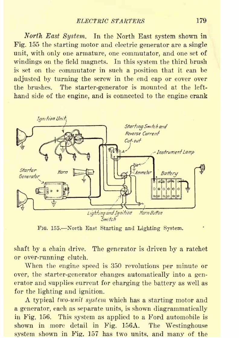
8/9/2019 (1921) Gasoline Automobiles
http://slidepdf.com/reader/full/1921-gasoline-automobiles 191/280
ELECTRIC STARTERS 179
North East System. In the North East system shown in
Fig. 155 the starting motor and electric generator are a single
unit, with only one armature, one commutator, and one set of
windings on the field magnets. In this system the third brush
is set on the commutator in such a position that it can be
adjusted by turning the screw in the end cap or cover over
the brushes. The starter-generator is mounted at the left-
hand side of the engine, and is connected to the engine crank
Igm
Starting'Snitch ancf
Reverse Current
Cuf- out
J
Lightingand
IgnitionHorn Button
Switch
FIG. 155. North East Starting and Lighting System.
shaft by a chain drive. The generator is driven by a ratchet
or over-running clutch.
When the enginespeed
is 350 revolutions
perminute or
over, the starter-generator changes automatically into a gen-
erator and supplies current for charging the battery as well as
for the lighting and ignition.
A typical two-unit system which has a starting motor and
a generator, each as separate units, is shown diagrammatically
in Fig. 156. This system as applied to a Ford automobile is
shown in more detail in Fig. 156A. The Westinghouse
shown in 157 has two and of the
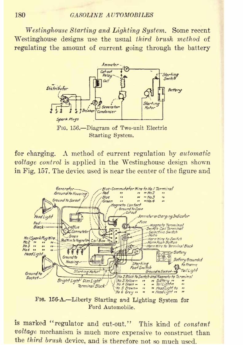
8/9/2019 (1921) Gasoline Automobiles
http://slidepdf.com/reader/full/1921-gasoline-automobiles 192/280
180 GASOLINE AUTOMOBILES
Westinghouse Starting and Lighting System. Some recent
Westinghouse designs use the usual third brush method of
regulating the amount of current going through the battery
FIG. 156. Diagram of Two-unit Electric
Starting System.
for charging. A method of current regulation by automatic
voltage control is applied in the Westinghouse design shownin Fig. 157. The device used is near the center of the figure and
Generator...... .-- Blue-Commut/rfarW/ra -to No. I Terminal
Ground-toHousfnq-' / .- ted " " "M>.2 "
l/f;' .-Hue "NbJ -
:
'
sGrttntn " " "Mo.4
-Magneto Contact
..Ammetar or
Otarginglndicator
Coil Terminal...Stltcfive Snitch..-Horn
'Ho. 6Grey
> >Headlight
Fie. 156-A. Liberty Starting and Lighting System for
Ford Automobile.
is marked "regulator and cut-out." This kind of constant
voltage mechanism is much more expensive to construct than
the third brush and is therefore not so much
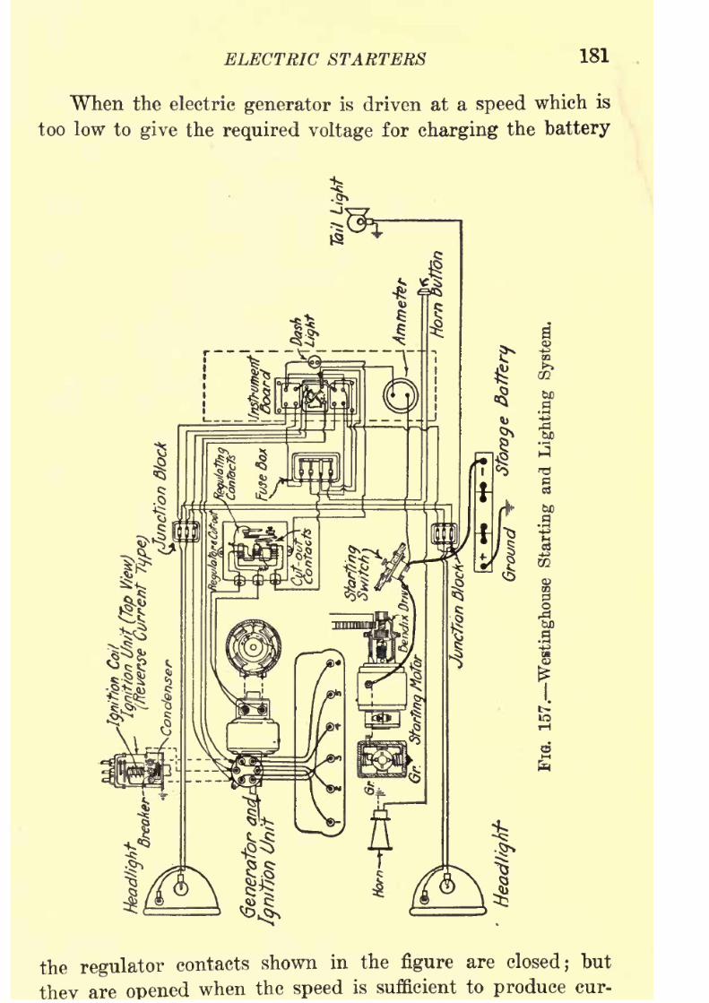
8/9/2019 (1921) Gasoline Automobiles
http://slidepdf.com/reader/full/1921-gasoline-automobiles 193/280
ELECTRIC STARTERS 181
When the electric generator is driven at a speed which is
too low to give the required voltage for charging the battery
the regulator contacts shown in the figure are closed; but
are when the speed is sufficient to produce cur-

8/9/2019 (1921) Gasoline Automobiles
http://slidepdf.com/reader/full/1921-gasoline-automobiles 194/280
182 GASOLINE AUTOMOBILES
the voltage and current tend to exceed the established rate the
magnetic pull of the electromagnets under the contact arm is
increased and pulls open the contact points. The effect of
this opening of the contacts is to put additional resistance
into the circuit supplying current to the electromagnets (field
magnets) 011 the generator, with a resulting drop in voltage
and current so that the magnetic pull of the electromagnets
under the contact arm is immediately decreased so that the
contacts close again. This opening and closing of the contacts
is so rapid that the voltage and current are held constant.
The maximum charging current can be increased by turning
the regulating adjusting screw on top of the contact arm so as
to increase the tension of the spring on the contact points.
The charging current in the apparatus should not exceed
twelve amperes.
TheWestinghouse system
shown in
Fig.157 has a Bendix
drive on the starting motor;but this system is sometimes made
with an electromagnetic gear shift on the starting motor (see
page 173).
Large electric head lights require a great deal of current.
Unless the storage battery is fully charged the requirements
of lighted head lights for electric current will reduce the
battery capacity so that there will be little reserve power for
running an electric starter, especially in cold weather when the
starter requires a large amount of current. It is a good idea,
therefore, to turn off the head lights if there is likelihood of
difficulty in starting the engine.
On many automobiles there is a device for "dimming"
the electric head lights which reduces the amount of light bypassing the electric current through a high-resistance coil. As
this device is used there are two electric switches controlling
the lights. One of these is for the circuit including the
"dimming" resistance; the other for the "undimmed" lights.
The dim lights are intended for use when the automobile is
standing or when passing other automobiles if the bright
lights are objectionable because of glare. The best way to

8/9/2019 (1921) Gasoline Automobiles
http://slidepdf.com/reader/full/1921-gasoline-automobiles 195/280
ELECTRIC STARTERS 183
whenever the switch on the circuit for bright lights is closed.
It is then a very simple matter in passing other automobiles
to open quickly the switch for bright lights and the electric
current will continue to go through the lights of the"dim-
ming" circuit. The other way of using these switches is
very ojectionable : that is, by opening the switch for bright
lights and then closing the switch for "dimming." This
method leaves a short interval when the head lights give no
light at all. There is a further advantage of having the
"dimming" switch closed whenever the head lights are used,
as it is not very likely that one will then leave an automobile
standing without lighted head lights. There is a small elec-
trical loss in the use of a high-resistance "dimming" device
of this kind; but practically all this loss is eliminated when
the two switches are used together as explained, because then
very little electric current goes through the "dimming"resistance.
It is a good idea for owners of automobiles to study the
wiring diagrams of their automobiles and to trace from time
to time the current from the battery through each light,
through the ignition system, through the horn, and through
every other electrical device used on the automobile, includingthe generator and starting motor. It is also a good practice
for the owner to carry the wiring diagram of his automobile
when touring so as to give information and assistance to
inexperienced garage men.
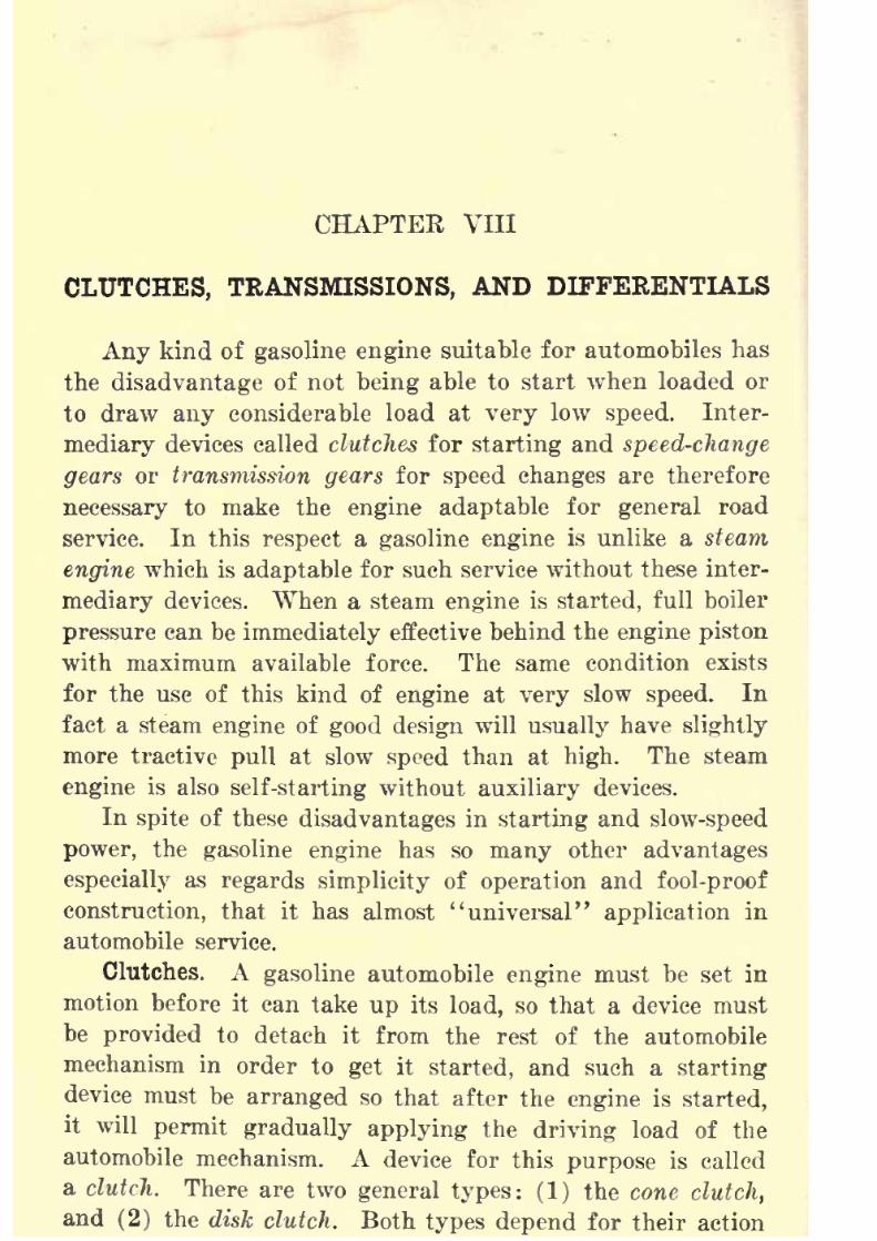
8/9/2019 (1921) Gasoline Automobiles
http://slidepdf.com/reader/full/1921-gasoline-automobiles 196/280
CHAPTER VIII
CLUTCHES, TRANSMISSIONS, AND DIFFERENTIALS
Any kind of gasoline engine suitable for automobiles has
the disadvantageof not
beingable to start when loaded or
to draw any considerable load at very low speed. Inter-
mediary devices called clutches for starting and speed-change
gears or transmission gears for speed changes are therefore
necessary to make the engine adaptable for general road
service. In this respect a gasoline engine is unlike a steam
engine which is adaptable for such service without these inter-
mediary devices. When a steam engine is started, full boiler
pressure can be immediately effective behind the engine piston
with maximum available force. The same condition exists
for the use of this kind of engine at very slow speed. In
fact a steam engine of good design will usually have slightly
more tractive pull at slow speed than at high. The steam
engine is also self-starting without auxiliary devices.
In spite of these disadvantages in starting and slow-speed
power, the gasoline engine has so many other advantages
especially as regards simplicity of operation and fool-proof
construction, that it has almost "universal" application in
automobile service.
Clutches. A gasoline automobile engine must be set in
motion before it can take up its load, so that a device must
be provided to detach it from the rest of the automobile
mechanism in order to get it started, and such a starting
device must be arranged so that after the engine is started,
it will permit gradually applying the driving load of the
automobile mechanism. A device for this purpose is called
a clutch. There are two general types: (1) the cone clutch,
and (2) the disk clutch. Both types depend for their action
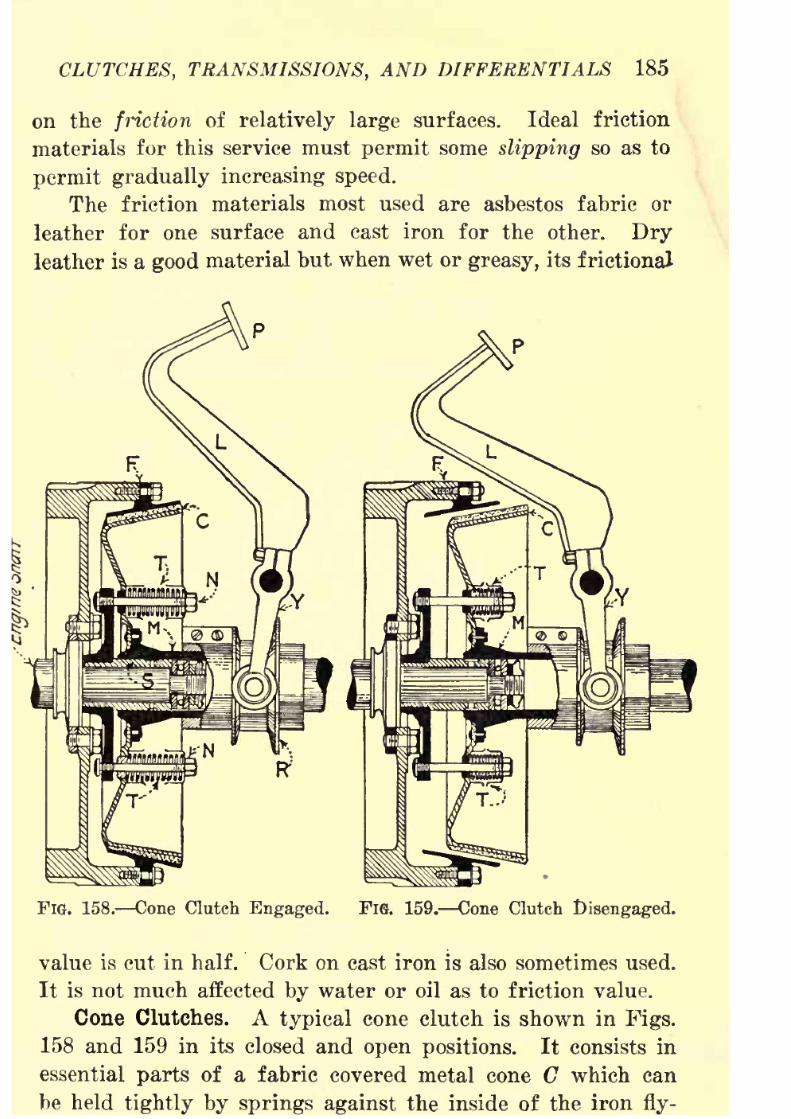
8/9/2019 (1921) Gasoline Automobiles
http://slidepdf.com/reader/full/1921-gasoline-automobiles 197/280
CLUTCHES, TRANSMISSIONS, AND DIFFERENTIALS 185
on the friction of relatively large surfaces. Ideal friction
materials for this service must permit some slipping so as to
permit gradually increasing speed.
The friction materials most used are asbestos fabric or
leather for one surface and cast iron for the other. Dry
leather is a good material but when wet or greasy, its frictional
FIG. 158. Cone Clutch Engaged. Fie. 159. Cone Clutch Disengaged.
value is cut in half. Cork on cast iron is also sometimes used.
It is not much affected by water or oil as to friction value.
Cone Clutches. A typical cone clutch is shown in Figs.
158 and 159 in its closed and open positions. It consists in
essential parts of a fabric covered metal cone C which can
be held tightly by springs against the inside of the iron fly-
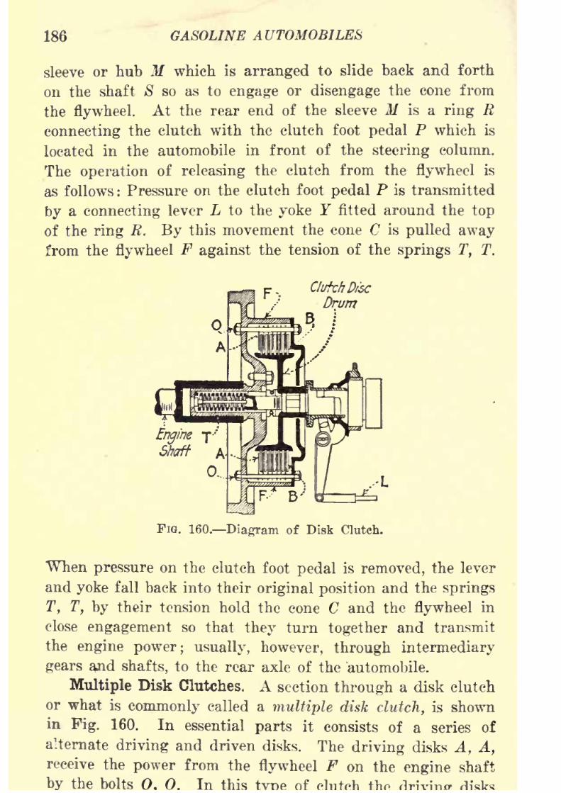
8/9/2019 (1921) Gasoline Automobiles
http://slidepdf.com/reader/full/1921-gasoline-automobiles 198/280
186 GASOLINE AUTOMOBILES
sleeve or hub M which is arranged to slide back and forth
on the shaft S so as to engage or disengage the cone from
the flywheel. At the rear end of the sleeve M is a ring R
connecting the clutch with the clutch foot pedal P which is
located in the automobile in front of the steering column.
The operation of releasing the clutch from the flywheel is
as follows : Pressure on the clutch foot pedal P is transmitted
by a connecting lever L to the yoke T fitted around the top
of the ring R. By this movement the cone C is pulled away
from the flywheel F against the tension of the springs T, T.
Clutch Disc
Drum
FIG. 160. Diagram of Disk Clutch.
When pressure on the clutch foot pedal is removed, the lever
and yoke fall back into their original position and the springs
T, T, by their tension hold the cone C and the flywheel in
close
engagement so that they turn together and transmitthe engine power; usually, however, through intermediary
gears a^id shafts, to the rear axle of the 'automobile.
Multiple Disk Clutches. A section through a disk clutch
or what is commonly called a multiple disk clutch, is shown
in Pig. 160. In essential parts it consists of a series of
alternate driving and driven disks. The driving disks A, A,
receive the power from the flywheel F on the engine shaft
the bolts 0. In this

8/9/2019 (1921) Gasoline Automobiles
http://slidepdf.com/reader/full/1921-gasoline-automobiles 199/280
CLUTCHES, TRANSMISSIONS, AND DIFFERENTIALS 187
are thin steel plates, fastened together by bolts. The driven
disks, B, B, consist of plates sometimes with holes in them
into which pieces of cork are pressed. In the position for
transmitting power the tension of the clutch spring T holds
the driving disks A, A, and driven disks B, B, in close contact.
Pressure on the clutch foot pedal compresses the clutch spring
T so that the two sets of disks separate, and the driving disks
gradually come to rest and stop the automobile.
Thedriving
plates of disk clutches, also, are often thin
disks faced with molded asbestos fabric, which has been
/^ / ^x^^ -\ >:
RRK
FIG. 161. Multiple Disk Cluteh.
treated with linseed oil and baked, and the driven disks are
plain steel plates.
A modification of this diagrammatic arrangement is shown
in Fig. 161 in which the driving disks are connected to the
drum D on the flywheel by sliding projections P, P, P, fitting
loosely into grooves or slots G, G, G.
The holding power of a disk type of clutch is the sum
of the holding powers of the several disks. Therefore, by
increasing the number of disks, the holding power of the
clutch is increased. The advantage of this type over the cone
clutch is that a very large total frictional surface can be
obtained with the use of comparatively small diameters of

8/9/2019 (1921) Gasoline Automobiles
http://slidepdf.com/reader/full/1921-gasoline-automobiles 200/280
188 GASOLINE AUTOMOBILES
The type of disk clutch described is intended for dry fric-
tional surfaces. Some clutches of this type are made to
operate in a bath of oil, so that in their disengaged position
the surfaces of the disks are partly covered with oil. Whenthe clutch foot-pedal is released and the springs pull the disks
together, the coating of oil on the frictional surfaces is gradu-
ally squeezed out. The oil bath makes possible a very gradual
engagement of one set of disks on the other so as to avoid
jerky clutch operation.
Speed-change Gear Sets. Transmissions. When an auto-
mobile engine has just been started and the clutch has been
released, the engine must be run relatively fast and the auto-
FIG. 162. Leverage of Gearing.
mobile slowly to avoid4
'stalling." Gradually the speed of
the automobile should be increased to get efficient, quiet
operation. Such speed changes suggest the use of gears.
Some may have difficulty in understanding the underlying
principle ofgearing,
so that apractical
illustration in
simplestterms will be explained. Fig. 162 shows two gear wheels
A and B meshed so that the teeth of one are between the teeth
of the other. Obviously in this position they must turn
together. Every time a tooth on the driving gear B advances
by rotation on its shaft the width of one tooth, the driven
gear A in contact with it will also advance one tooth. If
both gears have the same number of teeth they will turn at
the same speed. On the other if the

8/9/2019 (1921) Gasoline Automobiles
http://slidepdf.com/reader/full/1921-gasoline-automobiles 201/280
CLUTCHES, TRANSMISSIONS, AND DIFFERENTIALS 180
gear has ten teeth and the driven gear has sixty teeth, the
driving gear will make six (60-^-10) times as many revolu-
tions as the driven (larger) gear.
The above explanation applies only to the principle of
speed changes, but force or "power" changes with gears in
automobile operation are equally important. A portion of
each of the gears in Fig. 162 is drawn with shading to explain
the force changes occurring with speed changes. When driving
an automobile, one changes to the slowly moving gears ("lowgear") to get larger forces at the wheel for heavy pulling.
In this "gear change" the engine continues to give the same
horsepower as before, but the forces are different. These
forces and speed changes may be explained by comparison
with a lever as in Fig. 163. The ratio of the lengths of the
FIG. 163. Example of Leverage.
lever arms on each side of the point of support F is six;
(6-^1) so that with a load of ten pounds at the right-hand
end, the smallest amount of load in excess of sixty pounds
will overbalance the right-hand end and in the resulting move-
ment this end will move six times as far as the left-hand
end. The ratio of movement (or speed) is therefore, the
exact opposite (inverse) of the ratio of weights. Similarly,
a gear rotating one-sixth as fast as its driver has six times
as much turning force at its shaft. In other words, if the
gear in Fig. 162 with radius R^^ is six times as large as the
one with radius R2 ,
it turns only one-sixth as fast, but has
six times as much turning, pulling or pushing force at its
shaft.*
*
This idea of increased tractive pulling power at low speed overthat at high must not be confused with the previous statement that

8/9/2019 (1921) Gasoline Automobiles
http://slidepdf.com/reader/full/1921-gasoline-automobiles 202/280
190 GASOLINE AUTOMOBILES
There are three general types of speed-change gear sets:
(1) Selective sliding gears, which are arranged so that any
of the speeds can be selected at will. (2) Progressive sliding
gears, which do not permit selection of speeds at random, but
the speed changes must be in a definite order or in succession,
that is, one cannot for a three-speed gear move the gear
shifting lever out of the position for high speed, put it into
"neutral" position, and then immediately into the low-speed
position. When using this kind of speed-change gears, it is
necessary to actually put in contact the gears of the inter-
mediate speed before low-speed gears can be put together.
(3) Planetary gears, which are a combination of a clutch
and a simplified sliding gear set. The first and third arrange-
ments are most used.
Selective Sliding Gear Type. Fig. 164 shows, somewhat
simplified
as todetails,
aspeed-change gear
set of the selective
FIG. 164. Direct Drive on
Selective Sliding Gears.
FiQ. 165. Low-speed Gearing.
kind arranged for sliding operation. Two shafts 8 and T are
shown in this figure. The left-hand end of the shaft 8 is
rigidly connected to the clutch and therefore rotates normally
at engine speed. This shaft as shown here is not continuous
but is really two separate shafts which meet end to end and
are coupled together. The two shafts can be separated as
shown by dotted lines in Fig. 165. When the shaft 8Z
is
coupled to Sj, as in Fig. 164, both shafts will rotate at engine
that the powerstrokes, although powerful,
are so farapart
that there
is not sufficient carrying power from one power stroke to the next, and
as a result the
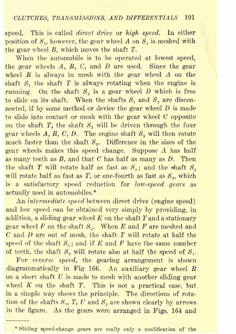
8/9/2019 (1921) Gasoline Automobiles
http://slidepdf.com/reader/full/1921-gasoline-automobiles 203/280
CLUTCHES, TRANSMISSIONS, AND DIFFERENTIALS 191
speed. This is called direct drive or high speed. In either
position of S2 , however, the gear wheel A on ^x is meshed with
the gear wheel B, which moves the shaft T.When the automobile is to be operated at lowest speed,
the gear wheels A, B, C, and D are used. Since the gear
wheel B is always in mesh with the gear wheel A on the
shaft $! the shaft T is always rotating when the engine is
running. On the shaft S2
is a gear wheel D which is free
to slide on its shaft. When the shafts Si and 82 are discon-
nected, if by some method or device the gear wheel D is made
to slide into contact or mesh with the gear wheel C opposite
on the shaft T, the shaft S2will be driven through the four
gear wheels A, B, C, D. The engine shaft S^ will then rotate
much faster than the shaft S2
. Difference in the sizes of the
gear wheels makes this speed change. Suppose A has half
as many teeth as B, and that C has half as many as D. Thenthe shaft T will rotate half as fast as 8
t ;and the shaft S
2
will rotate half as fast as T, or one-fourth as fast as S ltwhich
is a satisfactory speed reduction for low-speed gears as
actually used in automobiles.*
An intermediate speed between direct drive (engine speed)
and lowspeed
can be obtainedvery simply by providing,
in
addition, a sliding gear wheel E on the shaft T and a stationary
gear wheel F on the shaft S2
. When E and F are meshed and
C and D are out of mesh, the shaft T will rotate at half the
speed of the shaft Sl ;
and if E and F have the same number
of teeth, the shaft 82will rotate also at half the speed of 8^
For reverse speed, the gearing arrangement is shown
diagrammatically in Fig 166. An auxiliary gear wheel Ron a short shaft U is made to mesh with another sliding gear
wheel K on the shaft T. This is not a practical case, but
in a simple way shows the principle. The directions of rota-
tion of the shafts 8 lf T, U and S2 are shown clearly by arrows
in the figure. As the gears were arranged in Figs. 164 and
*Sliding speed -change gears are really only a modification of the
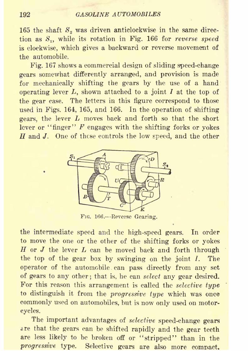
8/9/2019 (1921) Gasoline Automobiles
http://slidepdf.com/reader/full/1921-gasoline-automobiles 204/280
192 GASOLINE AUTOMOBILES
165 the shaft S2was driven anticlockwise in the same direc-
tion as $!, while its rotation in Fig. 166 for reverse speed
is clockwise, which gives a backward or reverse movement of
the automobile.
Fig. 167 shows a commercial design of sliding speed-change
gears somewhat differently arranged, and provision is made
for mechanically shifting the gears by the use of a hand
operating lever L, shown attached to a joint / at the top of
the gear case. The letters in this figure correspond to those
used in Figs. 164, 165, and 166. In the operation of shifting
gears, the lever L moves back and forth so that the short
lever or "finger" F engages with the shifting forks or yokes
H and J. One of these controls the low speed, and the other
K.
FIG. 166. Reverse Gearing.
the intermediate speed and the high-speed gears. In order
to move the one or the other of the shifting forks or yokes
H or J the lever L can be moved back and forth through
the top of the gear box by swinging on the joint /. The
operator of the automobile . can pass directly from any set
of gears to
anyother
;that is, he can select
any geardesired.
For this reason this arrangement is called the selective type
to distinguish it from the progressive type which was once
commonly used on automobiles, but is now only used on motor-
cycles.
The important advantages of selective speed-change gears
ire that the gears can be shifted rapidly and the gear teeth
are less likely to be broken off or "stripped" than in the
progressive type. Selective are also more

8/9/2019 (1921) Gasoline Automobiles
http://slidepdf.com/reader/full/1921-gasoline-automobiles 205/280
CLUTCHES, TRANSMISSIONS, AND DIFFERENTIALS 193
making possible shorter and therefore, stiffer shafts in the
gear box.
These descriptions of sliding gear sets have referred to
_.....Main Shaft--5Z
JoAxle Drive Shaft-
'-Drive End
^!:;* Lai/Shaft-
^ForLowSpeed
'Forlni-ermedicrhe Speed
FIG. 167. Typical Speed-Change Gears or Transmission.
three speeds ahead and one reverse. Some sets, however,
particularly those intended for very high speed automobiles
Neutral Gear Position
Fig. 168. Gear Wheels A and B connected.
are supplied with gears giving four speeds ahead. The fourth
speed is sometimes arranged to drive the axle drive shaft
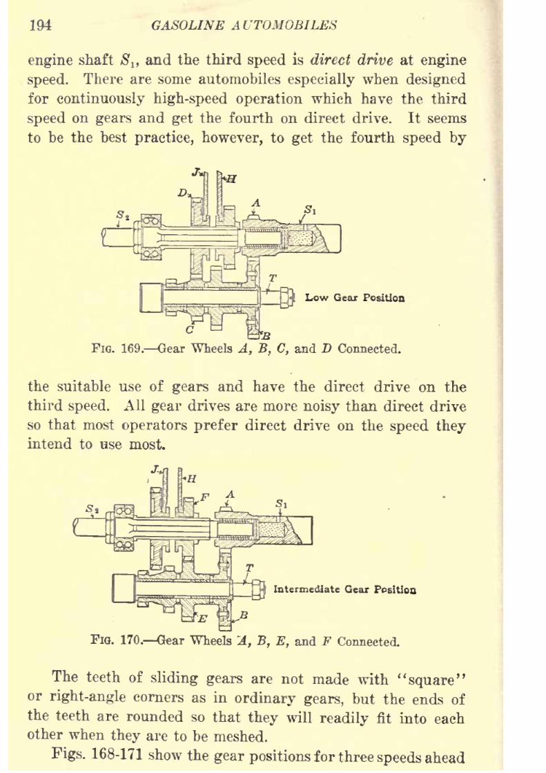
8/9/2019 (1921) Gasoline Automobiles
http://slidepdf.com/reader/full/1921-gasoline-automobiles 206/280
194 GASOLINE A UTOMOBILES
engine shaft 8lfand the third speed is direct drive at engine
speed. There are some automobiles especially when designed
for continuously high-speed operation which have the third
speed on gears and get the fourth on direct drive. It seemsto be the best practice, however, to get the fourth speed by
Low Gear Position
FIG. 169. Gear Wheels A, B, C, and D Connected.
the suitable use of gears and have the direct drive on the
third speed. All gear drives are more noisy than direct drive
so that most operators prefer direct drive on the speed they
intend to use most.
Intermediate Gear Position
FIG. 170. Gear Wheels 'A, B, E, and F Connected.
The teeth of sliding gears are not made with "square"or right-angle corners as in ordinary gears, but the ends of
the teeth are rounded so that they will readily fit into each
other
when they are to be meshed.Figs. 168-171 show the gear positions for three speeds ahead

8/9/2019 (1921) Gasoline Automobiles
http://slidepdf.com/reader/full/1921-gasoline-automobiles 207/280
CLUTCHES, TRANSMISSIONS, AND DIFFERENTIALS 195
and neutral in a typical selective sliding gear set. In the
neutral position shown in the first of the figures, the gears
A and B are the only ones meshed and the axle drive shaft$
2 or the "main drive shaft" is idle.
High Gear Position
Fie. 171. Shafts 8t and 8, Connected.
Shifting1
Lever for Speed-change Gears. Fig. 172 shows
the positions of the shifting lever on the speed-change gears
or the transmission as operated on automobiles with the
Revetermediate
FIG. 172. Usual Type of Gear Shifting Lever.
usual type of selective sliding gears as shown in Figs. 167
and 168. The usual position of the shifting lever and speed-
change gears with respect to the engine is shown in Fig. 173.
Dodge Automobile Speed-change Gears. In the speed-
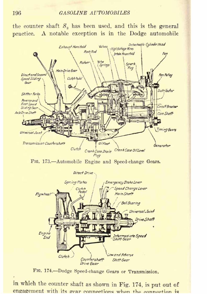
8/9/2019 (1921) Gasoline Automobiles
http://slidepdf.com/reader/full/1921-gasoline-automobiles 208/280
196 GASOLINE AUTOMOBILES
the counter shaft S2has been used, and this is the general
practice. A notable exception is in the Dodge automobile
Detachable CylimkrHeadExhaustHanifold
UnivtrsalJoint .-
Transmission Countershaft
Ctu**
FIG. 173. Automobile Engine and Speed-change Gears.
Direct Drive -.
Flywheel"
Spring Plates i
EmergencyBrakeLevtr
'
' - tr+ -SpeedChange Layer
MainShaft-
UniYtrsatJoi'rrf
DriveSftaft
Countershaft StirftGear
Drive 6ear
FIG. 174. Dodge Speed-change Gears or Transmission.
in which the counter shaft as shown in Fig. 174, is put out of
with
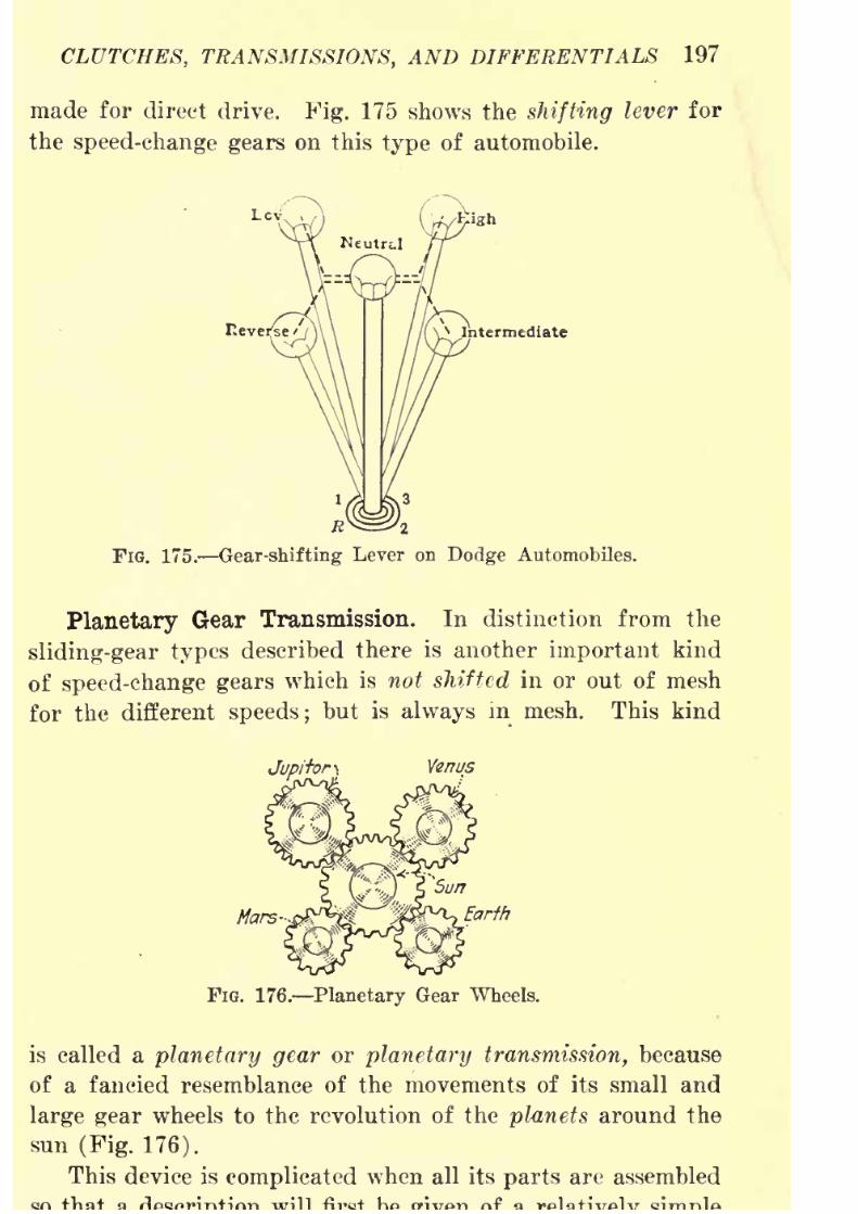
8/9/2019 (1921) Gasoline Automobiles
http://slidepdf.com/reader/full/1921-gasoline-automobiles 209/280
CLUTCHES, TRANSMISSIONS, AND DIFFERENTIALS 197
made for direct drive. Fig. 175 shows the shifting lever for
the speed-change gears on this type of automobile.
VVIntermediate
R
FIG. 175. Gear-shifting Lever on Dodge Automobiles.
Planetary Gear Transmission. In distinction from the
sliding-gear types described there is another important kind
of speed-change gears which is not shifted in or out of mesh
for the different speeds ;but is always in mesh. This kind
Jup/f'or Venus
Mars- Earth
FIG. 176. Planetary Gear Wheels.
is called a planetary gear or planetary transmission, because
of a fancied resemblance of the movements of its small and
large gear wheels to the revolution of the planets around the
sun (Fig. 176).
This device is complicated when all its parts are assembled
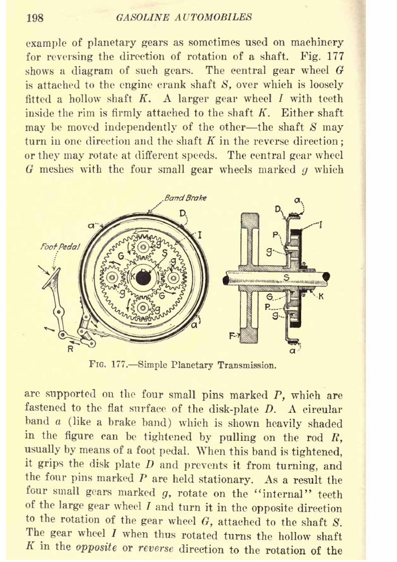
8/9/2019 (1921) Gasoline Automobiles
http://slidepdf.com/reader/full/1921-gasoline-automobiles 210/280
198 GASOLINE AUTOMOBILES
example of planetary gears as sometimes used on machinery
for reversing the direction of rotation of a shaft. Fig. 177
shows a diagram of such gears. The central gear wheel G
is attached to the engine crank shaft S, over which is loosely
fitted a hollow shaft K. A larger gear wheel / with teeth
inside the rim is firmly attached to the shaft K. Either shaft
may be moved independently of the other the shaft 8 mayturn in one direction and the shaft K in the reverse direction
;
or they may rotate at different speeds. The central gear wheel
G meshes with the four small gear wheels marked y which
BandBrake
a
FIG. 177. Simple Planetary Transmission.
are supported on the four small pins marked P, which are
fastened to the flat surface of the disk-plate D. A circular
band a (like a brake band) which is shown heavily shaded
in the figure can be tightened by pulling on the rod R,
usually by means of a foot pedal. When this band is tightened,
it grips the disk plate D and prevents it from turning, andthe four pins marked P are held stationary. As a result the
four small gears marked g, rotate on the ''internal" teeth
of the large gear wheel / and turn it in the opposite direction
to the rotation of the gear wheel G, attached to the shaft 8.
Thegear
wheel 7
when thus rotated turns the hollow shaftK in the opposite or reverse direction to the rotation of the

8/9/2019 (1921) Gasoline Automobiles
http://slidepdf.com/reader/full/1921-gasoline-automobiles 211/280
CLUTCHES, TRANSMISSIONS, AND DIFFERENTIALS 199
shaft 8. If the diameter of the gear wheel G is one-half the
diameter of the gear wheel / the shaft K will rotate at half
the speed of 8. Thus it will be seen this set of planetary
gears not only gives reversed direction but also speed
reduction.
Ford Planetary Speed-change Gears. An assembled view
of the speed-change gears of the planetary transmission used
in Ford automobiles is shown in Fig. 178, and the respective
Flywheel-...
Triple.Gear'"
Triple6eaf
Pin-D
Driven Gear
SlowSpeedGear
Reverse Gear--
Reverse Drum
fClutch Discs
I(Clutch DiscDrum
,..-ClutchDiscPush
ffing
fIufc/7Springs
-Clutch Shift
._Dr/ver Gear
Transmission
\Shaft
'
Brake Drum
FIG. 178. Ford Planetary Transmission.
parts are shown disconnected in Fig. 179. The engine fly-
wheel Fis
rigidly attachedto
the engine crank shaft C. Threesteel pins D are fastened to the flywheel. A gear wheel with
three sets of teeth E, F, G is fitted loosely so that it can
turn on each of these pins. Another gear wheel K fits over
the crank shaft C and meshes with the "E" teeth of each
of the gears on the pins D. The number of teeth on K is
the same as on E. There is, therefore, no speed change
through these gears, as, all move with the same number of
revolutions. The K is
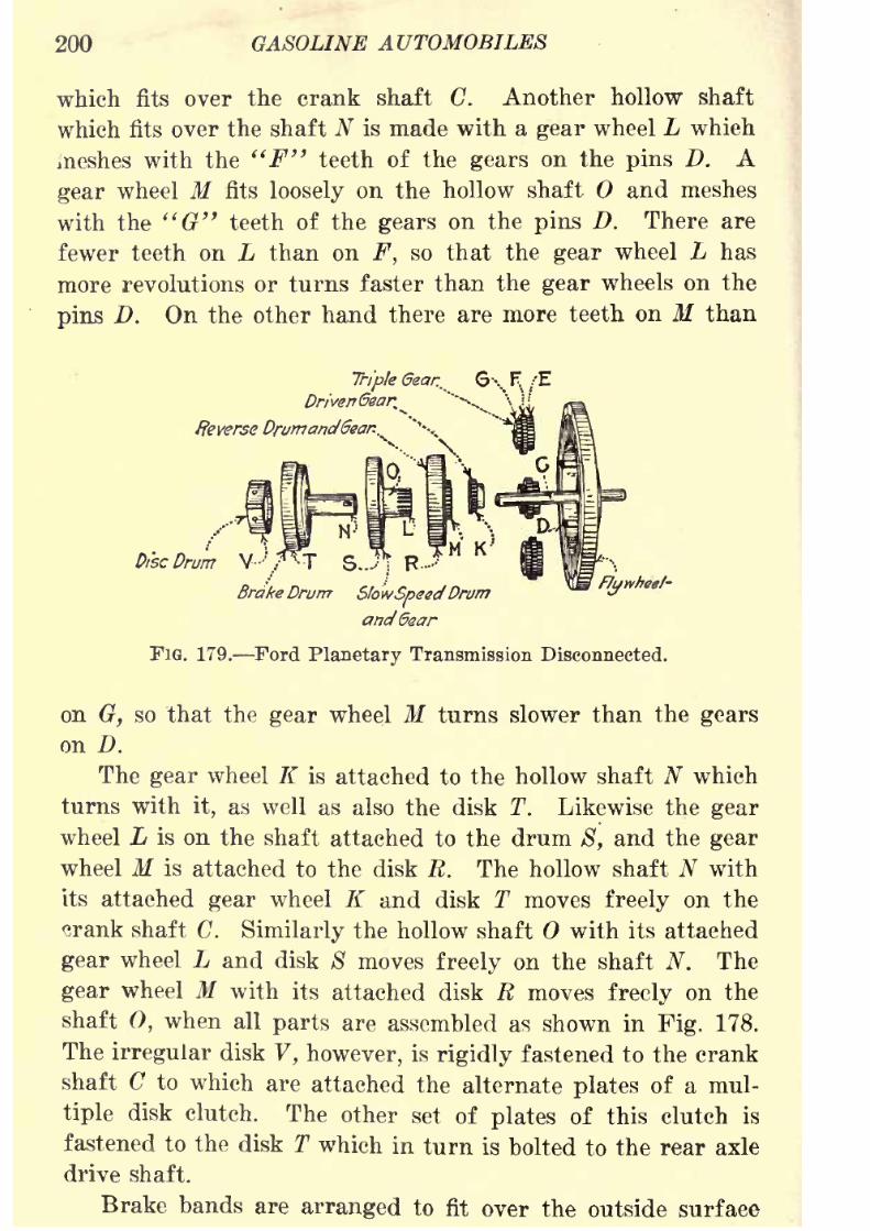
8/9/2019 (1921) Gasoline Automobiles
http://slidepdf.com/reader/full/1921-gasoline-automobiles 212/280
200 GASOLINE AUTOMOBILES
which fits over the crank shaft C. Another hollow shaft
which fits over the shaft N is made with a gear wheel L which
meshes with the "F" teeth of the gears on the pins D. A
gear wheel Mfits loosely on the hollow shaft and meshes
with the "G" teeth of the gears on the pins D. There are
fewer teeth on L than on F, so that the gear wheel L has
more revolutions or turns faster than the gear wheels on the
pins D. On the other hand there are more teeth on M than
TripleGear.
Driven'Gear^
Reverse Drumanddear..
F/ytvheef-
FiG. 179. Ford Planetary Transmission Disconnected.
*rakeDrurrr ShwSpsedDrum
and6ear
on G, so that the gear wheel M turns slower than the gears
on D.
The gear wheel K is attached to the hollow shaft N whichturns with it, as well as also the disk T. Likewise the gear
wheel L is on the shaft attached to the drum 8, and the gear
wheel M is attached to the disk R. The hollow shaft N with
its attached gear wheel K and disk T moves freely on the
crank shaft C. Similarly the hollow shaft with its attached
gear wheel L and disk 8 moves freely on the shaft N. The
gear wheel M with its attached disk R moves freely on the
shaft 0, when all parts are assembled as shown in Fig. 178.
The irregular disk V, however, is rigidly fastened to the crank
shaft C to which are attached the alternate plates of a mul-
tiple disk clutch. The other set of plates of this clutch is
fastened to the disk T which in turn is bolted to the rear axle
drive shaft.
Brake bands are arranged to fit over the outside surface
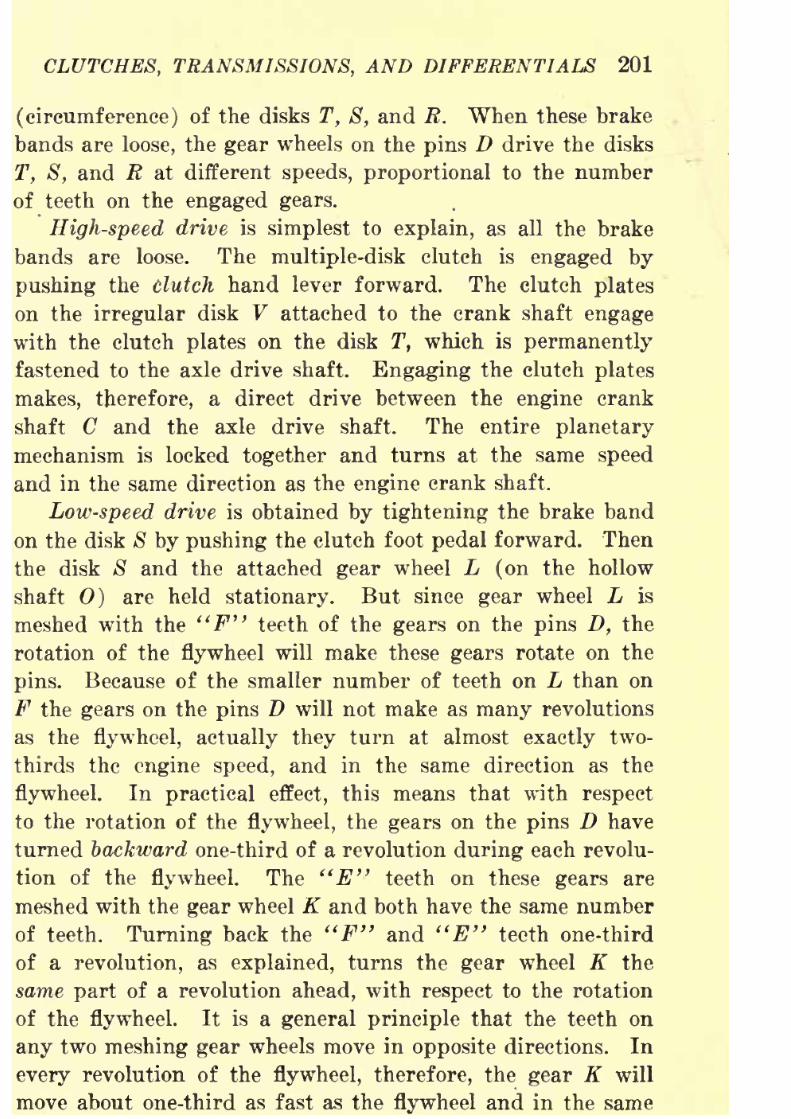
8/9/2019 (1921) Gasoline Automobiles
http://slidepdf.com/reader/full/1921-gasoline-automobiles 213/280
CLUTCHES, TRANSMISSIONS, AND DIFFERENTIALS 201
(circumference) of the disks T, S, and R. When these brake
bands are loose, the gear wheels on the pins D drive the disks
T, S, and R at different speeds, proportional to the numberof teeth on the engaged gears.
High-speed drive is simplest to explain, as all the brake
bands are loose. The multiple-disk clutch is engaged by
pushing the clutch hand lever forward. The clutch plates
on the irregular disk V attached to the crank shaft engage
with the clutchplates
on the disk T, which is
permanentlyfastened to the axle drive shaft. Engaging the clutch plates
makes, therefore, a direct drive between the engine crank
shaft C and the axle drive shaft. The entire planetary
mechanism is locked together and turns at the same speed
and in the same direction as the engine crank shaft.
Low-speed drive is obtained by tightening the brake band
on the disk S by pushing the clutch foot pedal forward. Then
the disk 8 and the attached gear wheel L (on the hollow
shaft 0) are held stationary. But since gear wheel L is
meshed with the "F" teeth of the gears on the pins D, the
rotation of the flywheel will make these gears rotate on the
pins. Because of the smaller number of teeth on L than on
F the gears on the pins D will not make as many revolutions
as the flywheel, actually they turn at almost exactly two-
thirds the engine speed, and in the same direction as the
flywheel. In practical effect, this means that with respect
to the rotation of the flywheel, the gears on the pins D have
turned backward one-third of a revolution during each revolu-
tion of the flywheel. The "E" teeth on these gears are
meshed with the gear wheel K and both have the same number
of teeth. Turning back the "F" and "E" teeth one-third
of a revolution, as explained, turns the gear wheel K the
same part of a revolution ahead, with respect to the rotation
of the flywheel. It is a general principle that the teeth on
any two meshing gear wheels move in opposite directions. In
every revolution of the flywheel, therefore, the gear K will
move about one-third as fast as the flywheel and in the same
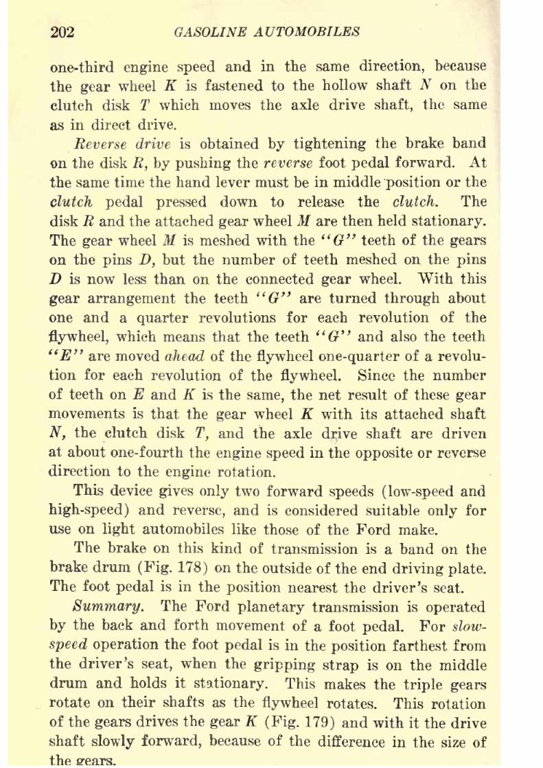
8/9/2019 (1921) Gasoline Automobiles
http://slidepdf.com/reader/full/1921-gasoline-automobiles 214/280
202 GASOLINE AUTOMOBILES
one-third engine speed and in the same direction, because
the gear wheel K is fastened to the hollow shaft N on the
clutch disk T which moves the axle drive shaft, the same
as in direct drive.
Reverse drive is obtained by tightening the brake band
on the disk R, by pushing the reverse foot pedal forward. At
the same time the hand lever must be in middle position or the
clutch pedal pressed down to release the clutch. The
disk R and the attached gear wheel M are then held stationary.
The gear wheel M is meshed with the "G" teeth of the gears
on the pins D, but the number of teeth meshed on the pins
D is now less than on the connected gear wheel. With this
gear arrangement the teeth "G" are turned through about
one and a quarter revolutions for each revolution of the
flywheel, which means that the teeth "G" and also the teeth
"E" are moved ahead of the flywheel one-quarter of a revolu-
tion for each revolution of the flywheel. Since the number
of teeth on E and K is the same, the net result of these gear
movements is that the gear wheel K with its attached shaft
N, the clutch disk T, and the axle drive shaft are driven
at about one-fourth the engine speed in the opposite or reverse
direction to the engine rotation.
This device gives only two forward speeds (low-speed and
high-speed) and reverse, and is considered suitable only for
use on light automobiles like those of the Ford make.
The brake on this kind of transmission is a band on the
brake drum (Fig. 178) on the outside of the end driving plate.
The foot pedal is in the position nearest the driver's seat.
Summary.The
Ford planetary transmissionis
operatedby the back and forth movement of a foot pedal. For slow-
speed operation the foot pedal is in the position farthest from
the driver's seat, when the gripping strap is on the middle
drum and holds it stationary. This makes the triple gears
rotate on their shafts as the flywheel rotates. This rotation
of the gears drives the gear K (Fig. 179) and with it the drive
shaft slowly forward, because of the difference in the size of
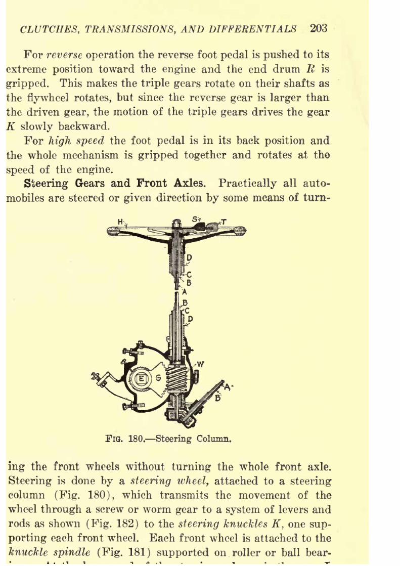
8/9/2019 (1921) Gasoline Automobiles
http://slidepdf.com/reader/full/1921-gasoline-automobiles 215/280
CLUTCHES, TRANSMISSIONS, AND DIFFERENTIALS 203
For reverse operation the reverse foot pedal is pushed to its
extreme position toward the engine and the end drum R is
gripped.This makes the
triple gearsrotate
ontheir shafts as
the flywheel rotates, but since the reverse gear is larger than
the driven gear, the motion of the triple gears drives the gear
K slowly backward.
For high speed the foot pedal is in its back position and
the whole mechanism is gripped together and rotates at the
speed of the engine.
Steering Gears and Front Axles. Practically all auto-
mobiles are steered or given direction by some means of turn-
FlQ. 180. Steering Column.
ing the front wheels without turning the whole front axle.
Steering is done by a steering wheel, attached to a steering
column (Fig. 180), which transmits the movement of the
wheel through a screw or worm gear to a system of levers and
rods as shown (Fig. 182) to the steering knuckles K, one sup-
porting eachfront
wheel. Each front wheelis
attached to theknuckle spindle (Fig. 181) supported on roller or ball bear-

8/9/2019 (1921) Gasoline Automobiles
http://slidepdf.com/reader/full/1921-gasoline-automobiles 216/280
204 GASOLINE AUTOMOBILES
(Fig. 182)'. From this arm, motion is transmitted to the short
arm K on the steering knuckle by means of the drag link D
which moves directly the front wheel of the automobile on
w
FIG. 181. Steering Knuckle.
the driver's side. The other wheel is moved by the tie rod R
(sometimes called transverse drag link). The steering
knuckles are fastened to the front axle by hinged connections
FlG. 182. Steering Gear and Front Axle.
on king bolts, so that the front wheels are free to swing
through nearly a quarter circle about the king bolt as a center.
This gives the wheels the necessary turning movement in
steering.

8/9/2019 (1921) Gasoline Automobiles
http://slidepdf.com/reader/full/1921-gasoline-automobiles 217/280
CLUTCHES, TRANSMISSIONS, AND DIFFERENTIALS 205
Fig. 180 shows the essential parts of a typical well-made
steering gear. Inside the steering column is the steering tube;
the upper end is connected to the steering wheel H and thelower end to a worm gear W. When the steering wheel is
turned it moves the steering tube and the worm gear at its end
in the same direction. The gear segment G meshing with the
worm gear turns the attached arm L (Fig. 182) or steering
lever so that it pulls or pushes on the drag link D, and
indirectly on the tie-rod R. The drag link and the tie-rod
move the steering knuckles on the front wheels.
A worm gear is an ideal device for steering gears as it is
non-reversible. While the slightest movement of the steering
wheel is readily transmitted by this device to the front wheels,
the up and down movement and jarring of the front wheels
on rough roads cannot appreciably jar or turn the steering
wheel. Inside the steering tube are (1) the tnrottle rod B,
going to the carbureter and (2) the spark control rod A con-
nected to the ''timer" which is the device for regulating the
time of ignition in the engine cylinders. These two rods
within the rim of the steering wheel are turned by the levers
T and 8. The spark lever S is attached to the rod A at the
center of the column and operates the small short rod A atthe lower end. The throttle lever T is attached to the tube B
and operates the short tube B. A foot lever, called an accel-
erator, is connected in most automobiles to the rods between the
short tube B on the steering column and the short lever on the
throttle valve of the carbureter.
The front axle of an automobile, unlike in an ordinary
wagon, is fastened by means of the springs to the frame of
the automobile and does not turn. The front wheels are not
parallel, but foregather slightly so that if the lines of the
wheels are projected forward far enough, they would meet
and make a pointed effect, like the bow of a boat. The effect
of this foregathering is to bring a slight but constant pressure
upon both wheels and makes them less likely to swerve through
contact with road unevenness. Also the wheels undergather,

8/9/2019 (1921) Gasoline Automobiles
http://slidepdf.com/reader/full/1921-gasoline-automobiles 218/280
206 GASOLINE AUTOMOBILES
of support of each knuckle so as to minimize the bending
stresses, as shown in Fig. 181. This deviation of the wheels
produces a slight wear on the tires, but is more than com-
pensated by the advantages. If the tie rod or the front axle
should be accidentally bent so that the foregather is increased,
there would be excessive wear of tires.
Bear Axles. The front and rear axles together support
the weight of the automobile. The front axle with its steer-
ing gear and links serves for steering, and the rear axle
with its gears transmit the power of the engine to the wheels.When the axle is stationary and is held firmly in place like
in a horse-drawn wagon, an automobile trailer, or some
kinds of trucks with chain drives, there is no special
mechanism necessary on the rear axles as the wheels are
free to turn on the ends of the axles. Such axles are called
"dead" axles. With this kind of wheel equipment there is
no difficulty in going around turns as each wheel is adjustable
to its own speed. In modern automobiles, however, the two
rear wheels are rigidly fastened to the rear axle which is
set in bearings so that it can rotate with the wheels. Such
a wheel and axle arrangement is called a "live" axle. If this
axle were made continuous, in one piece, the wheels could
only move together and with the axle, so that in going arounda sharp curve, if the wheel on the outside of the curve moved
normally, the one on the inside would have to move at the
same speed on account of their connection together and must
therefore slip on the ground.
At every turn in the road there would be some slipping,
and at
every sharpturn there would be
very much slippingwith excessive wear on tires. Besides the automobile would
not steer easily when making turns. It would be somethinglike running an automobile with a brake set on only one wheel.
On account of these difficulties it is obvious that some device
must be used to make possible separate and independentmovement of the two rear wheels and still permit the rigid
fastening of the wheels to the axle so that it can be used
to transmit the driving of the to wheels.
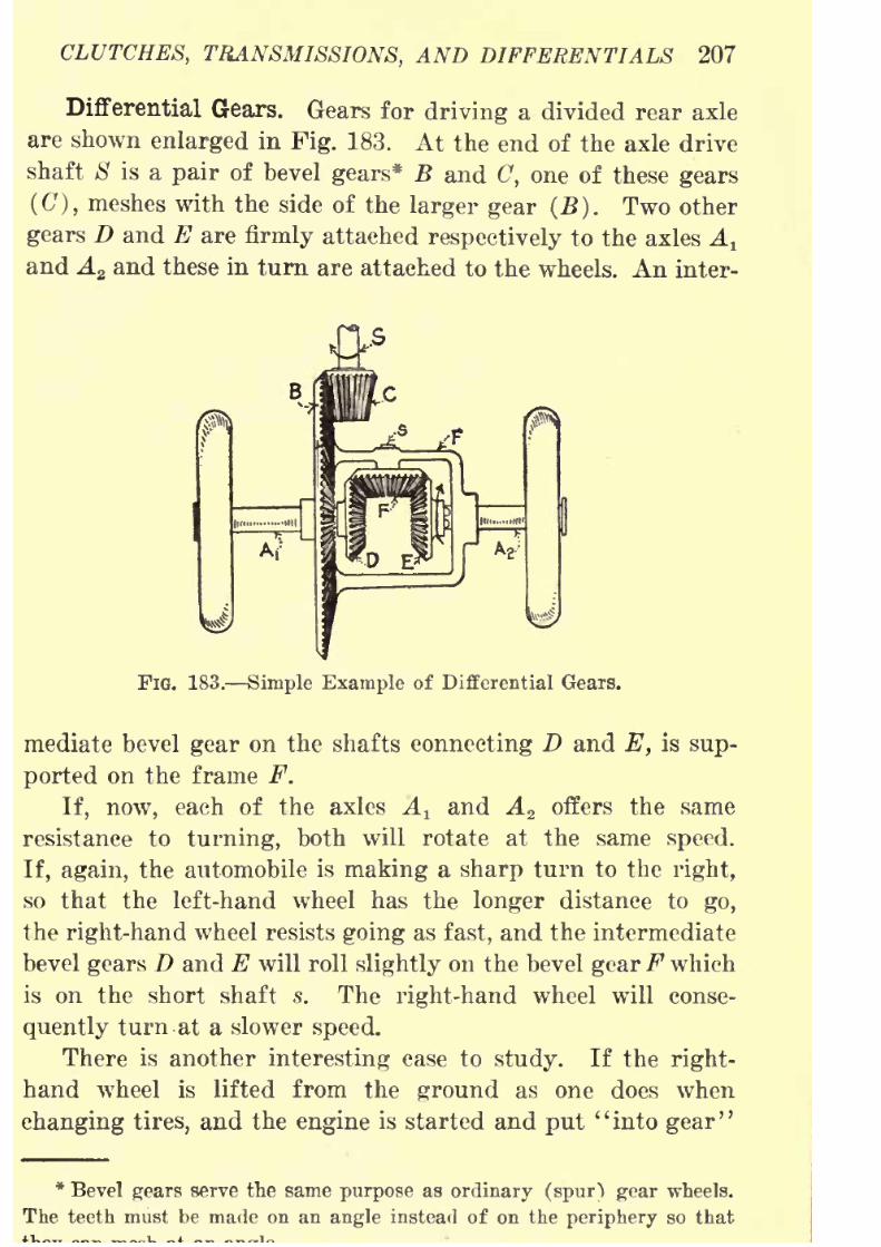
8/9/2019 (1921) Gasoline Automobiles
http://slidepdf.com/reader/full/1921-gasoline-automobiles 219/280
CLUTCHES, TRANSMISSIONS, AND DIFFERENTIALS 207
Differential Gears. Gears for driving a divided rear axle
are shown enlarged in Fig. 183. At the end of the axle drive
shaft 8 is a pair of bevel gears* B and C, one of these gears
(<7), meshes with the side of the larger gear (B). Two other
gears D and E are firmly attached respectively to the axles A t
and A2 and these in turn are attached to the wheels. An inter-
FiG. 183. Simple Example of Differential Gears.
mediate bevel gear on the shafts connecting D and E, is sup-
ported on the frame F.
If, now, each of the axles A land A 2 offers the same
resistance to turning, both will rotate at the same speed.
If, again, the automobile is making a sharp turn to the right,
so that the left-hand wheel has the longer distance to go,
the right-hand wheel resists going as fast, and the intermediate
bevel gears D and E will roll slightly on the bevel gearF which
is on the short shaft s. The right-hand wheel will conse-
quently turn at a slower speed.
There is another interesting case to study. If the right-
hand wheel is lifted from the ground as one does when
changing tires, and the engine is started and put "into gear"
*
Bevel gears serve the same purpose as ordinary (spur) gear wheels.The teeth must be made on an angle instead of on the periphery so that
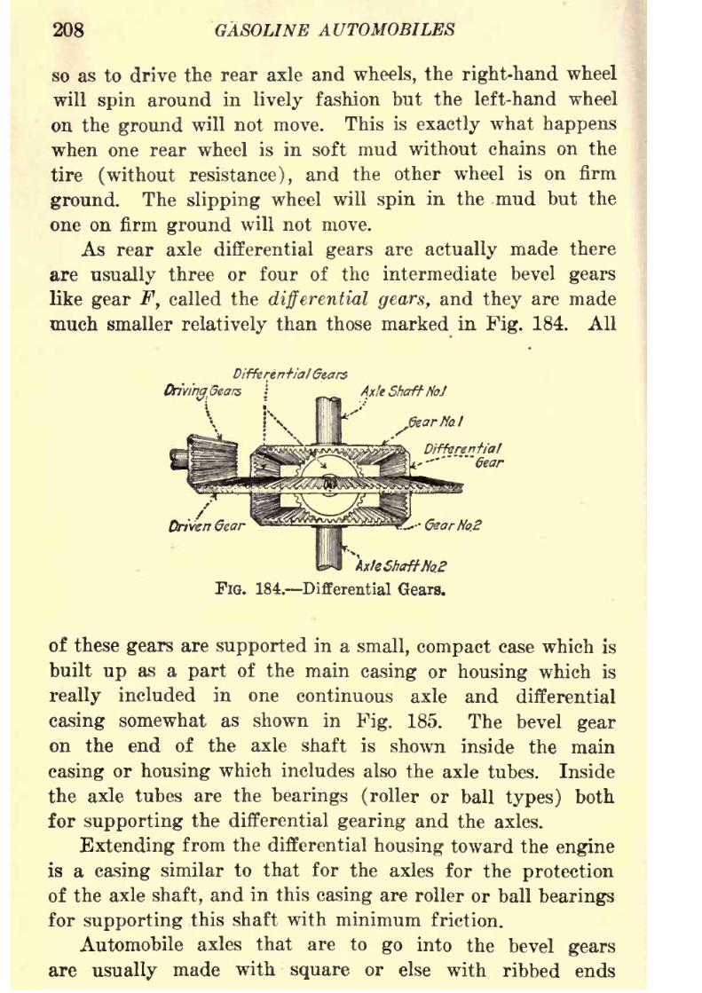
8/9/2019 (1921) Gasoline Automobiles
http://slidepdf.com/reader/full/1921-gasoline-automobiles 220/280
208 GASOLINE AUTOMOBILES
so as to drive the rear axle and wheels, the right-hand wheel
will spin around in lively fashion but the left-hand wheel
on the ground will not move. This is exactly what happens
when one rear wheel is in soft mud without chains on thetire (without resistance), and the other wheel is on firm
ground. The slipping wheel will spin in the mud but the
one on firm ground will not move.
As rear axle differential gears are actually made there
are usually three or four of the intermediate bevel gears
like gear F, called the differential gears, and they are made
much smaller relatively than those marked in Fig. 184. All
DifferentialGears
Driving.Gears \ ^^ Axle Shaft No>J
jSearffal
Driven Gear^
s^S^p^m^i... QearNo.2
\le ShaftHo.
FIG. 184. Differential Gears.
of these gears are supported in a small, compact case which is
built up as a part of the main casing or housing which is
really included in one continuous axle and differential
casing somewhat as shown in Fig. 185. The bevel gear
on the end of the axle shaft is shown inside the main
casing or housing which includes also the axle tubes. Inside
the axle tubes are the bearings (roller or ball types) both
for supporting the differential gearing and the axles.
Extending from the differential housing toward the engine
is a casing similar to that for the axles for the protection
of the axle shaft, and in this casing are roller or ball bearings
for supporting this shaft with minimum friction.
Automobile axles that are to go into the bevel gearsare usually made with square or else with ribbed ends

8/9/2019 (1921) Gasoline Automobiles
http://slidepdf.com/reader/full/1921-gasoline-automobiles 221/280
CLUTCHES, TRANSMISSIONS, AND DIFFERENTIALS 209
to slip into similarly shaped openings in the hubs of
these gears. The method of attaching the wheel ends of the
axles determines the type of axle construction.
FlG. 185. Casing or Housing of Differential Gears,
Kear Axle, and Roller Bearings.
Fig. 186 shows very clearly the differential gears, differ-
ential axle, axle shaft casings, roller bearings and wheel con-
Fio. 186. Parts of Standard Type of Rear Axle
Differential Gears.
struction of a Ford rear axle. The small differential gears
!,s2 ,
s3 ,
are very clearly shown.
Types of Differential Drives. There are several approved
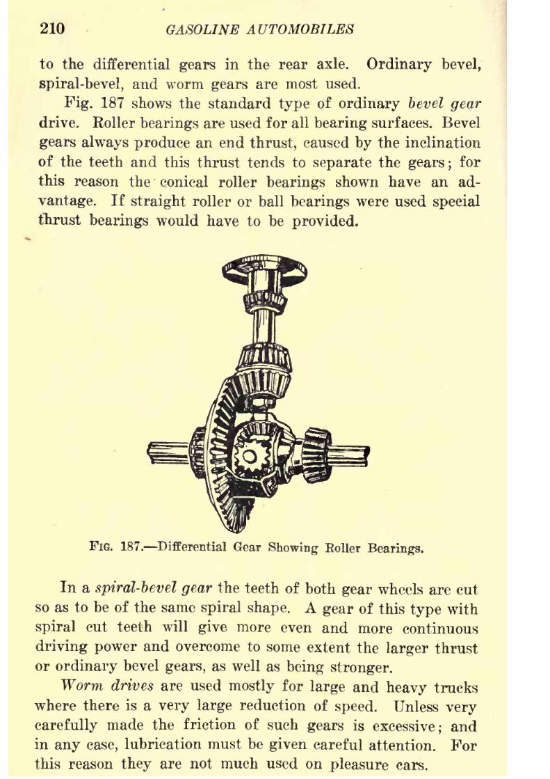
8/9/2019 (1921) Gasoline Automobiles
http://slidepdf.com/reader/full/1921-gasoline-automobiles 222/280
210 GASOLINE AUTOMOBILES
to the differential gears in the rear axle. Ordinary bevel,
spiral-bevel, and worm gears are most used.
Fig. 187 shows the standard type of ordinary bevel gear
drive. Roller bearings are used for all bearing surfaces. Bevel
gears always produce an end thrust, caused by the inclination
of the teeth and this thrust tends to separate the gears; for
this reason the conical roller bearings shown have an ad-
vantage. If straight roller or ball bearings were used special
thrust bearings would have to be provided.
FIG. 187. Differential Gear Showing Boiler Bearings.
In a spiral-bevel gear the teeth of both gear wheels are cut
so as to be of the same spiral shape. A gear of this type with
spiral cut teeth will give more even and more continuous
driving power and overcome to some extent the larger thrust
or ordinary bevel gears, as well as being stronger.
Worm drives are used mostly for large and heavy trucks
where there is a very large reduction of speed. Unless very
carefully made the friction of such gears is excessive; and
in any case, lubrication must be given careful attention. Forthis reason they are not much used on pleasure cars.
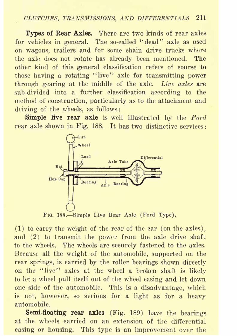
8/9/2019 (1921) Gasoline Automobiles
http://slidepdf.com/reader/full/1921-gasoline-automobiles 223/280
CLUTCHES, TRANSMISSIONS, AND DIFFERENTIALS 211
Types of Rear Axles. There are two kinds of rear axles
for vehicles in general. The so-called "dead" axle as used
on wagons, trailers and for some chain drive trucks wherethe axle does not rotate has already been mentioned. The
other kind of this general classification refers of course to
those having a rotating "live" axle for transmitting power
through gearing at the middle of the axle. Live axles are
sub-divided into a further classification according to the
method of construction, particularly as to the attachment and
driving of the wheels, as follows:
Simple live rear axle is well illustrated by the Ford
rear axle shown in Fig. 188. It has two distinctive services :
Q-T1"
FIG. 188. Simple Live Bear Axle (Ford Type).
(1) to carry the weight of the rear of the car (on the axles),
and (2) to transmit the power from the axle drive shaft
to the wheels. The wheels are securely fastened to the axles.
Because all the weight of the automobile, supported on the
rear springs, is carried by the roller bearings shown directly
on the "live" axles at the wheel a broken shaft is likely
to let a wheel pull itself out of the wheel casing and let down
one side of the automobile. This is a disadvantage, which
is not, however, so serious for a light as for a heavy
automobile.
Semi-floating rear axles (Fig. 189) have the bearings
at the wheels carried on an extension of the differential
casing or housing. This type is an improvement over the
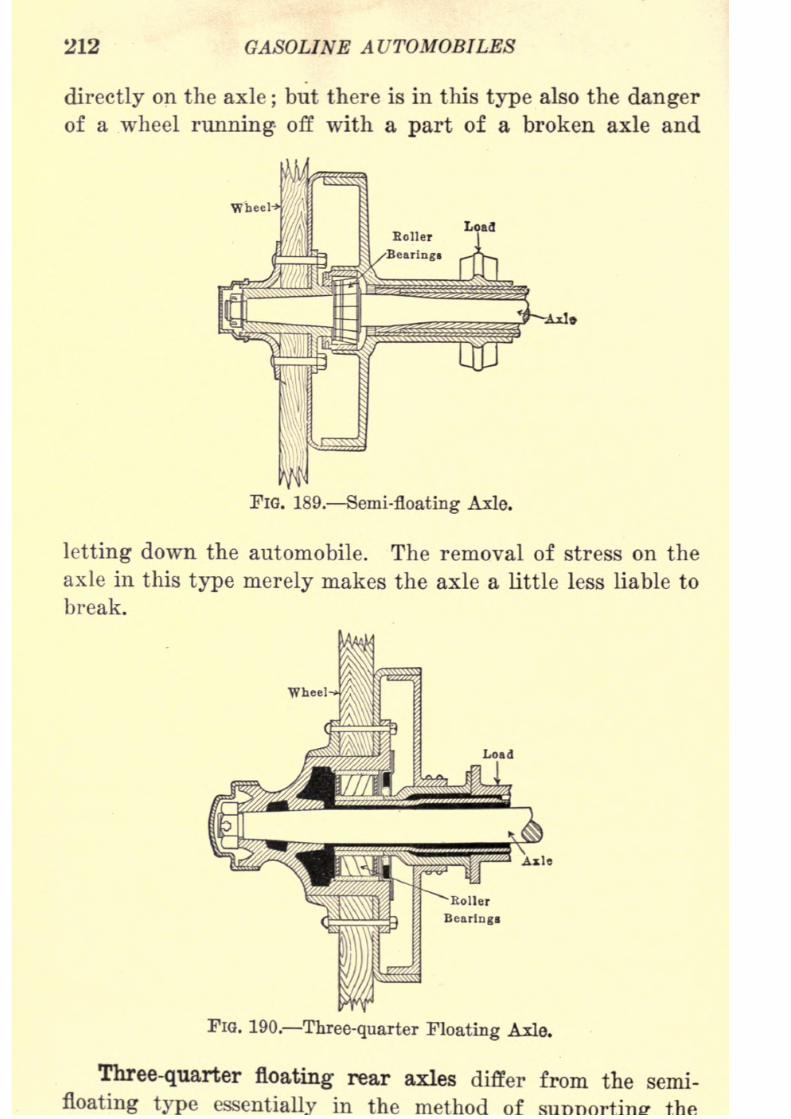
8/9/2019 (1921) Gasoline Automobiles
http://slidepdf.com/reader/full/1921-gasoline-automobiles 224/280
212 GASOLINE AUTOMOBILES
directly on the axle;but there is in this type also the danger
of a wheel running- off with a part of a broken axle and
FIG. 189. Semi-floating Axle.
letting down the automobile. The removal of stress on the
axle in this type merely makes the axle a little less liable to
break.
FIG. 190. Three-quarter Floating Axle.
Three-quarter floating rear axles differ from the semi-
floating type in the method of
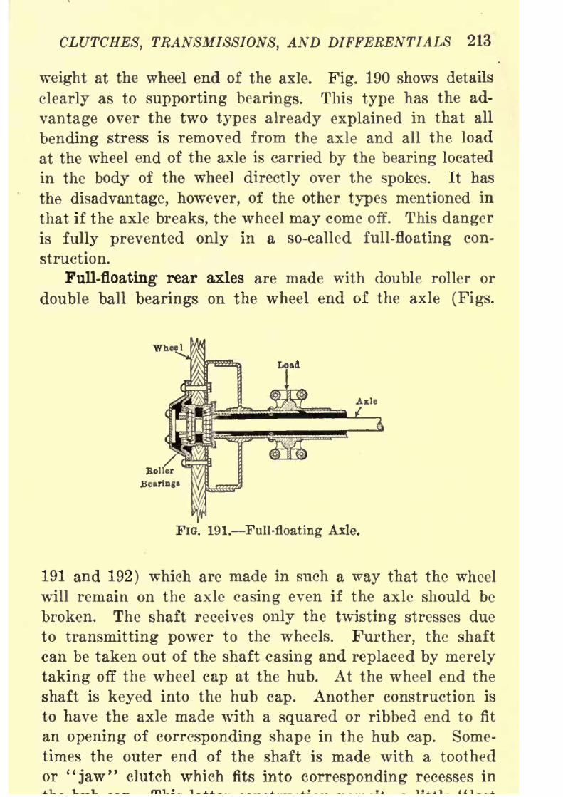
8/9/2019 (1921) Gasoline Automobiles
http://slidepdf.com/reader/full/1921-gasoline-automobiles 225/280
CLUTCHES, TRANSMISSIONS, AND DIFFERENTIALS 213
weight at the wheel end of the axle. Fig. 190 shows details
clearly as to supporting bearings. This type has the ad-
vantage over the two types already explained in thatall
bending stress is removed from the axle and all the load
at the wheel end of the axle is carried by the bearing located
in the body of the wheel directly over the spokes. It has
the disadvantage, however, of the other types mentioned in
that if the axle breaks, the wheel may come off. This danger
is fully prevented only in a so-called full-floating con-
struction.
Full-floating rear axles are made with double roller or
double ball bearings on the wheel end of the axle (Figs.
FIG. 191. Full-floating Axle.
191 and 192) which are made in such a way that the wheel
will remain on the axle casing even if the axle should be
broken. The shaft receives only the twisting stresses due
to transmitting power to the wheels. Further, the shaft
can be taken out of the shaft casing and replaced by merely
taking off the wheel cap at the hub. At the wheel end the
shaft is keyed into the hub cap. Another construction is
to have the axle made with a squared or ribbed end to fit
an opening of corresponding shape in the hub cap. Some-
times the outer end of the shaft is made with a toothed
or "jaw" clutch which fits into corresponding recesses in
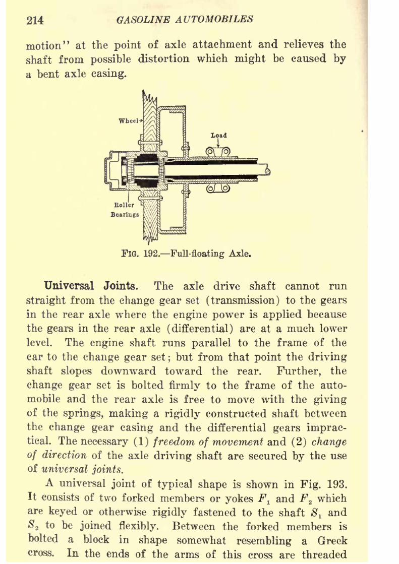
8/9/2019 (1921) Gasoline Automobiles
http://slidepdf.com/reader/full/1921-gasoline-automobiles 226/280
214 GASOLINE AUTOMOBILES
motion" at the point of axle attachment and relieves the
shaft from possible distortion which might be caused by
a bent axle casing.
FIG. 192. Full-floating Axle.
Universal Joints. The axle drive shaft cannot run
straight from the change gear set (transmission) to the gears
in the rear axle where the engine power is applied because
the gears in the rear axle (differential) are at a much lower
level. The engine shaft runs parallel to the frame of the
car to the change gear set ; but from that point the drivingshaft slopes downward toward the rear. Further, the
change gear set is bolted firmly to the frame of the auto-
mobile and the rear axle is free to move with the giving
of the springs, making a rigidly constructed shaft between
the change gear casing and the differential gears imprac-
tical. The necessary (1) freedom of movement and (2) change
of direction of the axle driving shaft are secured by the use
of universal joints.
A universal joint of typical shape is shown in Fig. 193.
It consists of two forked members or yokes F^ and F2which
are keyed or otherwise rigidly fastened to the shaft 8 tand
S2 to be joined flexibly. Between the forked members is
bolted a block in shape somewhat resembling a Greekcross. In the ends of the arms of this cross are threaded
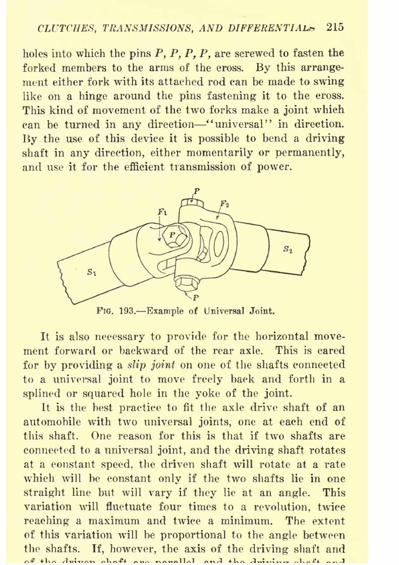
8/9/2019 (1921) Gasoline Automobiles
http://slidepdf.com/reader/full/1921-gasoline-automobiles 227/280
CLUTCHES, TRANSMISSIONS, AND DIFFERENTIAL* 215
holes into which the pins P, P, P, P, are screwed to fasten the
forked members to the arms of the cross. By this arrange-
ment either fork with its attached rod can be made to swing
like on a hinge around the pins fastening it to the cross.
This kind of movement of the two forks make a joint which
can be turned in any direction "universal" in direction.
By the use of this device it is possible to bend a driving
shaft in any direction, either momentarily or permanently,
and use it for the efficient transmission of power.
FIG. 193. Example of Universal Joint.
It is also necessary to provide for the horizontal move-
ment forward or backward of the rear axle. This is cared
for by providing a slip joint on one of the shafts connected
to a universal joint to move freely back and forth in a
splined or squared hole in the yoke of the joint.
It is the best practice to fit the axle drive shaft of an
automobile with two universal joints, one at each end of
this shaft. One reason for this is that if two shafts are
connected to a universal joint, and the driving shaft rotates
at a constant speed, the driven shaft will rotate at a rate
which will be constant only if the two shafts lie in one
straight line but will vary if they lie at an angle. This
variation will fluctuate four times to a revolution, twice
reaching a maximum and twice a minimum. The extent
of this variation will be proportional to the
anglebetween
the shafts. If, however, the axis of the driving shaft and
8/9/2019 (1921) Gasoline Automobiles
http://slidepdf.com/reader/full/1921-gasoline-automobiles 228/280
216 GASOLINE AUTOMOBILES
J;he driven shaft are connected by an intermediate shaft
fitted with a universal joint at each end, and if these joints
be arranged with their adjacent yokes in the same plane,
then the variations in speed of the first joint will be exactly
neutralized by the similar variation of the second joint, and
the axle drive shaft will rotate at a uniform speed.
It is obvious that the tendency of a single universal
joint is to give a jerky motion to the automobile, this jerky
motion increasing with the angle through which the
universal joint acts. Therefore, if properly installed, anaxle driven shaft with two universal joints is always better
than one with only one universal joint.
Another reason for the use of two universal joints is
that much greater range of action is permitted between the
rear axle and the frame which carries the power plant and
body. This allows the necessary freedom of movement of
the rear axle when passing over uneven road surfaces, with-
out producing excessive stresses which are unavoidable when
only a single universal joint is used. This explains whythe single-joint construction is not much used except in light-
weight automobiles.
Some automobiles of recent design have the engine set so
that the shaft tilts downward towards the back. The axle
drive shaft runs straight from the transmission to the normal
position of the differential. This is said to be a straight-line
drive.
Fabric universal joints which have been adopted by several
manufacturers are made by joining the ends of two shafts bymeans of circular fabric
(cottonand
rubber)disks.
A forgedsteel spider having three arms is welded or otherwise fastened
to the end of each shaft. The circular disks, usually three in
number, are placed between the spiders. Each spider is
independently bolted to the disks so that the arms of one come
between the arms of the other, necessitating six holes in the
disks. The arms are said to be "staggered." The "give and
take" of the disks is said to be sufficient to supply the neces-

8/9/2019 (1921) Gasoline Automobiles
http://slidepdf.com/reader/full/1921-gasoline-automobiles 229/280
CLUTCHES, TRANSMISSIONS, AND DIFFERENTIALS 217
sary end motion. Advantages claimed for this type of joint
are that it does not require lubrication and will not rattle.
Torque members. Torque means twisting effort. A simple
illustration of twisting effort and reaction is as follows: A
person stands in a boat on water and twists a pole held on
shore. The boat tips in the direction opposite to the twisting
force. To produce the same twist on the shore end of the
pole and keep the boat from tipping it can be supported to
the shore or lake bottom. The condition is similar to the
turning force of the drive shaft on the rear axle. The engine and
body are supported on the frame which rests at the rear end on
springs attached to the rear axle. The engine twists the drive
shaft. The axle and wheels rest on the ground and the frame tips
on the springs just as the boat tipped. For best results the frame
and axle should be fastened together so that the frame cannot
twist but can work up and down as the springs bend.It
maybe said that the springs will accomplish this and so they do to
a certain extent. The sole use of springs to take up this twist
is very common and will be spoken of later. The springs
have their own particular work to do and may be made smaller
if they are relieved of this additional strain by use of torque
members, rods, or tubes, which prevent this twisting reaction.
Radius Rods. In addition to the twisting stress there is
another stress developed between the rear axle and frame
due to the power transmitted to the rear wheels. This
is the reaction of the axle to the driving force. This stress
may be resisted by the springs or to relieve them, radius rods
may be used. If the rear wheels of an automobile rested on
rollers, free to turn, there would be no forward movement.If the wheels rest on something solid something that can
"push back" the car is pushed ahead and the push comes
through the axle to the frame of the car. One cannot row a
boat unless the oar locks are fastened down. The oars push
the row locks and the row locks push the boat. Just so the
wheelspush
the axle and the axlepushes
the car ahead or
back. Rods transmitting the driving force and fastened to

8/9/2019 (1921) Gasoline Automobiles
http://slidepdf.com/reader/full/1921-gasoline-automobiles 230/280
218 GASOLINE AUTOMOBILES
the frame, which pivot and allow the axle to move up and
down on a radius are called radius rods.
If the car has no torque members or radius rods it is said
to employ the Hotclikiss metTiod of driving. This method has
come into wide use. The springs and bolts connecting the
automobile frame to the rear axle are necessarily stronger
than when torque and radius rods are used. The entire stress
of driving the car comes through the front ends of the rear
springs.
Brakes. Both the foot brake (service brake] and handbrake (emergency brake] usually act on brake drums attached
to the rear wheels. Many cars are, however, now equipped
with the hand brake acting on a drum on the drive shaft
directly back of the transmission. This is called a trans-
mission brake. The emergency brake is mainly used to hold
the automobile at a standstill after it has been stopped. It
should always be set when the car is not moving.
Brake Drums. A rear axle is usually equipped with
service and emergency brakes. Brake drums are made out of
pressed steel and shaped like large round box covers from ten
to fifteen inches in diameter and two or three inches deep.
They are fastened rigidly to each rear wheel. Inside and
outside of the edges of these drums are circular bands of steel
faced or lined with asbestos fabric which has been treated
with a compound and baked. These bands are arranged so they
may be expanded or contracted to bind on the brake drum.
They are operated by levers, and rods or wire cables which
are moved by the foot pedal or hand lever.
Equalizers. When either the brakepedal
is
depressedor
the hand lever is pulled back, the corresponding band on the
brake drum of each rear wheel is tightened. If, as is often
the ease, a device is used to make each brake band grip the
same as the other, that device is called the brake equalizer,
sometimes brake differential. It may be only a simple lever
like the whipple-tree of a wagon or it may consist of bevel
gears.
8/9/2019 (1921) Gasoline Automobiles
http://slidepdf.com/reader/full/1921-gasoline-automobiles 231/280
CLUTCHES, TRANSMISSIONS, AND DIFFERENTIALS 219
Adjustment of Brakes. A type of shaft or transmission
brake operated by the hand lever has replaced one of the
two sets of rear wheel brakes on many cars. Springs arecombined with the brake band, as they are also in the case of
rear wheel brakes, so that when the lever or pedal is released
the band will separate itself from the brake drum an
appreciable distance. Additional springs are supplied to hold
the brake pedal and the hand lever in a non-engaged position.
A ratchet is provided to hold the hand lever in an engaged
position unless it is desired to release it. On all brakes there
are provided means for tightening or adjusting the rods and
bands.
It is needless to emphasize that brakes should be kept in
adjustment. In a released position it should be possible to
insert a small saw blade or case knife blade between the brake
band and drum all around. Too much opening interferes with
the quick action of the brake. If the brake band rubs it will
overheat and burn the asbestos facing.
Brake adjusting screws should be kept oiled as well as all
parts of the brake levers. Road water and water used in
washing the car rusts the brake parts quickly and adjusting
screws give considerable bother if they become rusty.
Several foreign cars have adopted front wheel brakes which
supplement the action of the rear wheel brakes, permitting a
quicker stop.
Operation of Brakes. Brakes should never be applied
quickly when the car is moving at more than fifteen or twenty
miles on a slippery road,level or
down grade.If
theyare
the car will skid or slide and cannot be steered. Accidents
are continually happening due to this cause. Anti-skid tire
chains offset the liability to danger from skidding, but are not
an absolute preventive.
The engine is a very effective brake when thrown into
low or intermediate speed. If other brakes fail, or to help
them out, shift the gears into low speed and let the clutch

8/9/2019 (1921) Gasoline Automobiles
http://slidepdf.com/reader/full/1921-gasoline-automobiles 232/280
220 GASOLINE AUTOMOBILES
back, so that the engine is in gear. If more braking action is
needed cut off the ignition.
On a long hill do not use the foot brake continually. Long
grades should be descended at a comparatively slow speed and
the hand or emergency brake used alternately with the foot
brake so that neither brake will become overheated. If one
brake is used continually in going down a mountain road or a
very long steep hill, or if the hill is descended at a high speed
the brake will get so hot that the brake lining will be injured.
Perhaps one of the greatest causes of brake failure is oil.
The oil which gets on the brakes usually works through the
rear axle housing from the differential gears. The owner may
put too much oil in the differential and it travels along the
inside of the axle tube. The oil works over the wheel bearing
and into the brake drum. It will often be noticed that the
oil collects mostly on the right-hand brake. This is because the
crown on the road, and the ditch alongside which are used in
passing other automobiles, tilt the automobile so that the
right-hand wheel is lower than the left-hand wheel.
Shock Absorbers. Shock absorbers slow up the movement
of the springs. They operate on either one of two general
principles ; (1
) the springs are made stiffer by the addition of
supplementary springs or (2) the movement of the springs is
dampened by some friction or compressed air device. Anautomobile often rides smoothly on roads with good surfaces,
yet when driven over rough roads at moderately high or high
speeds it jounces the occupants around badly. If the shock
absorbers only stiffen the springs the car will ride smoother
on the
roughroads
butwill
ride harder on good roads.The simplest form of shock absorber is a small rubber
bumper which is placed so as to come between the frame and
the axle when the spring has been considerably compressed.A common type is a supplementary coil spring which onlystiffens the car springs. This makes it possible to carryheavier loads and ride more comfortably over rough roads,
yet the car will not have the same slow spring action on boule-
vards.
8/9/2019 (1921) Gasoline Automobiles
http://slidepdf.com/reader/full/1921-gasoline-automobiles 233/280
CLUTCHES, TRANSMISSIONS, AND DIFFERENTIALS 221
More efficient types are made to connect the axle and
frame of the car with some friction or compressed-air device.
With the compressed-air shock absorber an air-cylinder shockabsorber and piston are connected, one with the frame and
the other to the axle of the car. By regulating the escape of
the compressed air the movement of the spring is slowed up as
is necessary. A variation of this principle is the employment
of oil instead of air.
Another type employs the principle of two levers, one
connected to the axle and the other to the frame of the car,
turning on a friction pad. The friction between these levers
may be varied. Still another type permits the axle to deflect
towards the frame but in so doing winds up a strap which
has to unwind before the spring comes back to normal. This
last type is called a "snubber" shock absorber.
Automatic Gear Shifts. Attempts have been made to
eliminate the gear-shifting lever in order to simplify the
driving of a car. One method, used on the Owen Magnetic
automobile, only partially accomplishes this but is very dis-
tinctive. On this car there are only two change-speed gears,
one forward and one reverse. When the gear lever is placed
in
' '
forward
' '
the different speed changes are made by simplymoving a selector lever on the steering wheel. The changes
in engine and car speed are not obtained by gears. All the
power of the engine is converted into electric power and the
car is driven by an electric motor mounted directly behind the
engine and dynamo. This dynamo is what converts the engine
power into electricity. Shifting the speed lever on the steer-
ing wheel controls the speed of the driving motor by changing
the brushes which supply current to it.
The Sauer, a German automobile which has been imported
into this country, has done away with the gear-shift lever.
On this car there is a set of gears and the desired speed or
combination of gears is chosen by a selecting mechanism in
conjunction with the clutch pedal. The driver may set the
selector lever at any time. Then when the clutch pedal is
8/9/2019 (1921) Gasoline Automobiles
http://slidepdf.com/reader/full/1921-gasoline-automobiles 234/280
222 GASOLINE AUTOMOBILES
selected. There is also a magnetic gear shift which American
automobile engineers have used experimentally and have
adopted on some automobiles. The gear set or transmission is
retained, as with the Sauer, and the desired combination of
gears is obtained by a selector lever on the steering wheel.

8/9/2019 (1921) Gasoline Automobiles
http://slidepdf.com/reader/full/1921-gasoline-automobiles 235/280
CHAPTER IX
LUBRICATION AND COOLING SYSTEMS
Friction. There is always friction between any two sur-faces which rub or "bear" on each other. Of two sets of
rubbing surfaces each of the same materials, the smoother
set will obviously have the less friction. But even what
we may call a smooth surface will appear, when looked at
through a microscope, to be not at all smooth as it appears
to the naked eye. Fig. 194 shows the relative roughness
as seen through the microscope of two carefully polished
plates of brass and of steel. There are a greater number
PIG. 194. Surfaces of Brass and FIG. 195. Surfaces of Brass and
Steel. Steel with Lubrication.
of rough places in the steel than in the brass, yet some
of the rough places will fit into each other, and the surfaces,
especially if pressed together as they would be when
weighted, will offer resistance to any sliding movement,
tending to increase the roughness.
Practically all the resistance to sliding can be removed,
however, if such moving parts are separated by a film of
engine oil as illustrated in Fig. 195. The oil acts as a sort
of cushion and to a large extent prevents the fitting together
of the rough places in the two surfaces. This figure givesan exaggerated idea of the fundamental principle of all

8/9/2019 (1921) Gasoline Automobiles
http://slidepdf.com/reader/full/1921-gasoline-automobiles 236/280
224 GASOLINE AUTOMOBILES
so long as a film of lubricating liquid is maintained between
the polished surfaces bearing on each other. The oil film
maybe
destroyedeither
(1)because no more oil can be
supplied to the bearing surfaces; or (2) because the bearing
surfaces are loaded too heavily and are pushed together
with so much force that the oil film is broken and the
conditions shown in Fig. 194 results. In either Case the
removal of the oil film will make the surfaces wear away
rapidly.
Surfaces Requiring Friction. It is essential that the fric-
tion of the various bearings in the engine, speed-change
gears, axles, etc., be made small so as to waste as little
as possible of the driving power. On the other hand there
are parts of an automobile such as the brakes which should
have no lubrication, or the friction clutch which in most
types should also have none. The brakes, friction clutch,
and the tires depend for their efficient action on large
frictional resistance over relatively small areas.
Oil in the Cylinders. Primarily, the tightly fitting
cast-iron rings on the engine pistons are to prevent the
explosive mixture admitted to the cylinders above the pistons
from escaping downward past the pistons into the crank
case. Inside the engine crank case of modern type engine
oil is splashed and sprayed continuously so that on the
up-stroke of each of the pistons the inside of the cylinder
is wetted completely by the oil. On the down-stroke of
the piston, practically all this oil should be swept down
by the piston rings, leaving only a thin film on the cylinder
walls for lubrication. If the engine oil used is too thinor the piston rings do not fit tightly enough, too much oil
will accumulate on the cylinder walls and some of it will
get into the explosion space at the top of the cylinder.
This excessive oil will be only partly burned as it is not
so combustible as gasoline and will make a black depositof carbon on the inside of the cylinder, on the
sparkplugs,
and on the valves. If this leakage of oil is in sufficient

8/9/2019 (1921) Gasoline Automobiles
http://slidepdf.com/reader/full/1921-gasoline-automobiles 237/280
LUBRICATION AND COOLING SYSTEMS 225
system is used for lubrication, one must be cautious to avoid
getting too much oil past the piston rings to the top of the
engine cylinder.If there is continual trouble with carbon deposits in
engine cylinders, a little kerosene poured in through the
priming cocks or through the holes for the spark plugs will
loosen the carbon so that it will be discharged with the
exhaust gases. Kerosene will not, however, prevent the
formation of carbon and the treatment must be repeated
once or twice a week.
When the engine is running with the throttle valve of
the carbureter nearly closed, there will be only a small
amount of explosive mixture entering the cylinders and in
consequence there is a decided vacuum on each intake stroke
of the piston. This vacuum has a tendency to draw oil past
the piston into the combustion chamber, where it burns andforms smoke. This is why, when an automobile is left
standing with the engine running for any length of time,
it will often be found to start away with clouds of smoke
issuing from the exhaust.
Kinds of Lubricants. Commonly used lubricants are
either liquids, called oils; or semi-solids, called greases and
semi-fluid oils. Oils are ordinarily used for the lubrication
of all parts of the engine and its auxiliary parts included
in the engine casing. Greases and semi-fluid oils are used
for the speed-change gears, differential gears, axles, wheels,
steering gear and springs. Some of the latter are lubricated
in many of the latest designs with oil, especially for such
parts like springs where only small amounts of oil or grease
are needed. One reason for the more extended use of oil
instead of grease is that grease is difficult to handle and
the filling of grease cups or containers is "messy" work.
Some dealers now sell grease in tablets to fit the standard
sizes of grease cups. This method eliminates much of the
objectionto the use of
greasefor small
bearings.Only mineral oils should be used for the oil supply of
8/9/2019 (1921) Gasoline Automobiles
http://slidepdf.com/reader/full/1921-gasoline-automobiles 238/280
226 GASOLINE AUTOMOBILES
generally used for the engines of racing automobiles and for
aeroplane engines because of the very high temperature which
it will
withstand;but is unsuitable for ordinary automobile
engines which operate at much lower cylinder temperatures,
because it tends to produce an excessive amount of carbon
in the cylinders and is besides expensive. Steam engine
cylinder oil is not suitable, first, because it is as a rule
too thick (too heavy "body") and if of ordinary power
plant grade will not withstand the heat in the cylinders of
gasoline automobile engines. It has its proper place for
engine lubrication in steam automobiles.
The ideal oil for gasoline engine cylinders would have
either of the two following qualities: (1) burning up com-
pletely if it got up past the piston rings, so that there would
be no carbon deposit, or (2) not burning at all and would
remain as oil no matter how high the temperature in enginecylinders. No oil can be made to meet such a requirement.
To determine quality, oils are tested (1) for flash point; that
is, the temperature at which a film of it will break down
by vaporization, and (2) for viscosity, showing at what tem-
perature it becomes so thin as to be worthless as a lubricant.
A good oil should have enough "body" to maintain an oil
film between the piston and the cylinder at the usual tem-
peratures in automobile engines and still it should not be
so thick as to interfere with the easy movement of the piston
rings in the cylinder.
A good quality of engine oil should be free from acids,
which have a tendency to make the working surfaces of both
the cylinder and pistons rough.
Flash-point Test. If oil is heated slowly in a cup in
which the bulb of a thermometer is immersed and the flame
of a taper or lighted match is held over the surface, it is
not difficult to observe the temperature at which there is
sufficient vapor escaping from the oil to be ignited. This
temperature at which the oil vapor ignites is called theflash
point of the oil. A good automobile engine oil should have
8/9/2019 (1921) Gasoline Automobiles
http://slidepdf.com/reader/full/1921-gasoline-automobiles 239/280
LUBRICATION AND COOLING SYSTEMS 227
Fire Test. If the procedure as outlined above for the
flash test is continued so that instead of having momentary
ignition flashes near the surface of the oil, the whole surface
of the oil takes fire and continues to burn, the observed tem-
perature is called the fire test.
Acid Test. A simple method to test for acid in oil is
to dissolve a small amount of the oil in warm alcohol and
dip a piece of blue litmus paper in the solution. If there
is acid in the oil it will turn the
paperred. Litmus
papercan be purchased at drug stores.
Oils and Greases for Automobiles. Most dealers in auto-
mobile engine oils have three grades according to thinness:
(1) light, (2) medium, and (3) heavy. Only the light and
medium grades should be used in engines having reasonably
tight or close-fitting piston rings. Heavy-grade oil may
be used for engines with piston rings which are not as tight
as they should be, and is invariably used for all kinds of
air-cooled automobile, and motor cycle engines. Sometimes
because of faulty ignition or other causes an engine becomes
so much heated that light and medium oil give little lubrica-
tion and are used up too rapidly. The only remedy then
is to use a temporarily heavier grade.The very thick oil (semi-fluid) of the kind used for the
lubrication of speed-change gears or transmissions as well
as also for the differential gears in the rear axle should
be of a kind that will adhere to the gear teeth for cushion-
ing effect, thus reducing both wear and noise. The speed-
change gears should be well provided with oil, so that the
lower teeth of the smallest gears will be in oil for their
full length. The differential gears should be filled with
heavy semi-fluid oil up to the level of the filling hole, making
the gear casing in the rear axle about one-third full. The
rear axle is not fluid-tight so that if relatively thin oil is
used in the differential casing it may leak from the ends
of the axles and splash over the brake bands, wheels, andrear axle. This leakage oil may interfere with the proper
8/9/2019 (1921) Gasoline Automobiles
http://slidepdf.com/reader/full/1921-gasoline-automobiles 240/280
228 GASOLINE AUTOMOBILES
removal is difficult without spoiling the paint. In case oil
in the differential works out at the ends of the axles, either
a heavier grade of transmission oil should be used or closer
fitting washers should be put at the ends of the axles. Wheel
bearings are packed in thin cup grease which need not be
replaced often if the wheels are not removed. Heavy grease
will not cling to roller or ball bearings such as are used
in the wheels of automobiles.
The lubrication of the steering gear is important as its
failure may cause a serious accident. Its parts should be
inspected when oiling an automobile to make sure there
is no undue wear. Grease and oil cups on the steering gear,
including the rods and levers connecting it to the front
wheels should always be kept well filled and should be tested
to see that the lubrication gets to the joints for which it
is intended. It is a good practice, especially where grease
is used to screw down the thread on the grease cups till
just a little grease can be seen oozing out from the bearing.
Insufficient lubrication in the engine is often the cause
of very large repair bills, and in the steering gear, of dis-
astrous accidents. It pays to look carefully after the lubri-
cation of an automobile. Lubrication is
cheaperthan
bearings.When an expert looks into the condition of an automobile,
one of the first places he inspects for wear is at the steering
knuckles. A constant supply of good grease or oil is needed
to prevent excessive wear at the knuckles. It is worth while
to screw down on the grease cups on the steering knuckles
every time oil is put in the engine. When a grease cup
is screwed down so that it cannot be turned further, it
should be filled immediately. There should be enough greasein the cups to keep forcing it out, so that grit cannot get
into the bearings.
The spring shackle bolts are sometimes equipped with
grease cups, and often the passages for the grease become
clogged so that one
mayscrew
down on the cup and onlyforce the grease out of the thread of the cup, instead of
8/9/2019 (1921) Gasoline Automobiles
http://slidepdf.com/reader/full/1921-gasoline-automobiles 241/280
LUBRICATION AND COOLING SYSTEMS 229
thread. In that case the grease cup should be taken off and
the passages cleaned.
There are fewer grease cups used on automobiles now
than formerly. Oil cups are being used instead, largely
because they are more conveniently filled.
At least once a year a small amount of grease should
be put between the leaves of automobile springs to keep
them in good operating condition without squeaking. This
can be done by raising the frame with an automobile jack
which has been blocked up high enough for the purpose.
When the weight on the frame is supported by the jack
it is not difficult to insert between the leaves of the spring
a wedge-shaped clamping device made for the purpose, or
even the ends of a screw-driver will do. After the leaves
have been separated, the very small amount of grease needed
can be easily putin.
Oil in a sense wears out in any lubricating system and
should be replaced with new oil occasionally. Some of it
will work up past the piston and be burned, but most of it
will remain in the sump longer than it should be used. All
of the gasoline that is taken into the cylinder is not burned.
Some of k is forced past the piston on the compression
stroke into the crank case, where it condenses and mixes
with the oil. This thins the oil sometimes to a point where
it has little or no lubricating value.
Most automobile instruction books advise draining all
the oil from the engine, from the speed-change gears, and
from the differential case at the end of every 1,000 or 2,000
miles, depending somewhat on whether the driving has been
heavy or light. After removing the old oil or semi-fluid
grease from these parts, they should be flushed with kerosene
in order to remove all sediment and metallic dust that mayhave accumulated. Heavy continuous service requires more
attention to lubrication than light service. Both before and
after a long touring trip over rough roads an automobile
should be given careful inspection for loose parts, excessive
8/9/2019 (1921) Gasoline Automobiles
http://slidepdf.com/reader/full/1921-gasoline-automobiles 242/280
230 GASOLINE AUTOMOBILES
If the oil supply should be exhausted while the auto-
mobile is in use, the engine will get stiff, lose its power,
and the friction of the unlubrieated parts will generate
sufficient heat to melt out the lining of the bearings. If
the engine runs for any length of time in this condition,
it may be wrecked beyond repair.
An automobile owner should not rely entirely on his
chauffeur for the care of parts of the automobile requiring
lubrication, unless he has found out that the man knows
the importance of lubrication. Nor should it be taken for
granted that the garage man is attending to the lubrication
of an automobile when he charges for that service. "Make
sure yourself" is the best rule.
Methods of Engine Lubrication. Lubricating systems for
automobile gasoline engines are usually of one of the three
following: (1) simple splaslisystem,
which is
entirelyauto-
matic, no pump being used; (2) splash system with an oil
pump, as an auxiliary; (3) fully forced feed (pump]
system.
Simple Splash System. In many medium and low-price
models of automobile engines, engine oil is poured into the
crank case to a level where the engine crank shaft dips
into it at each revolution. The rapid rotation of the cranks
through the oil in the bottom of the crank case splashes
it in all directions and produces a sort of oil foam that
covers the entire inside surface of the crank case and of
the cylinders below the pistons Each bearing has a hole
drilled at a place where the "splashed" oil can reach and then
rundown into the bearing.The difficulty with this system is that if the oil level
is a little too high there will be over-lubrication, that is
too much oil will be splashed, especially into the cylinders,and if the crank shaft does not dip deeply enough there
will be too little splashed oil to lubricate the bearings
properly. Frequent filling is therefore necessary to maintain
the proper oil level. This system is shown diagrammaticallyin 196.
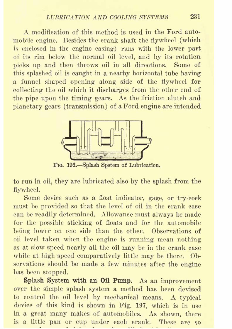
8/9/2019 (1921) Gasoline Automobiles
http://slidepdf.com/reader/full/1921-gasoline-automobiles 243/280
LUBRICATION AND COOLING SYSTEMS 231
A modification of this method is used in the Ford auto-
mobile engine. Besides the crank shaft the flywheel (which
is
enclosedin the
engine casing) runs with thelower
partof its rim below the normal oil level, and by its rotation
picks up and then throws oil in all directions. Some of
this splashed oil is caught in a nearby horizontal tube having
a funnel shaped opening along side of the flywheel for
collecting the oil which it discharges from the other end of
the pipe upon the timing gears. As the friction clutch and
planetary gears (transmission) of a Ford engine are intended
FlG. 196. Splash Spstem of Lubrication.
to run in oil, they are lubricated also by the splash from the
flywheel.
Some device such as a float indicator, gage, or try-cock
must beprovided
so that the level of oil in the crank case
can be readily determined. Allowance must always be made
for the possible sticking of floats and for the automobile
being lower on one side than the other. Observations of
oil level taken when the engine is running mean nothing
as at slow speed nearly all the oil may be in the crank case
while at high speed comparatively little may be there. Ob-
servations should be made a few minutes after the engine
has been stopped.
Splash System with an Oil Pump. As an improvementover the simple splash system a method has been devised
to control the oil level by mechanical means. A typical
device of this kind is shown in Fig. 197, which is in use
in a great many makes of automobiles. As shown, thereis a little pan or cup under each crank. These are so

8/9/2019 (1921) Gasoline Automobiles
http://slidepdf.com/reader/full/1921-gasoline-automobiles 244/280
232 GASOLINE AUTOMOBILES
"spoon" at the lower end of the connecting rod touches the
surface of the oil at its low point in each revolution and
splashes oil in all directions over the inside of the crank
case, and over practically all the working parts of the
engine. This splashing and agitation of the oil makes a
fog of oil in the crank case so that a film of oil is deposited
even on those parts which the splash does not reach. At the
right-hand side of the figure an engine-driven pump is shown
also diagrammatically which, when the engine is running,
pumps oil from the reservoir or "sump" in the bottom of
FlG. 197. Splash and Pump System of Lubrication.
the crank case to a horizontal distributing pipe, P. There
are holes in the side of this pipe from which oil discharges
into the pans to keep them constantly over-flowing and,
therefore, also at a constant level. The oil is constantlydrained back into the reservoir to be pumped back again
into the pans. This system maintains constant conditions
of lubrication irrespective of the amount of oil in the reser-
voir, consequently this reservoir can be made large to hold
a large amount of oil and makes frequent refilling unneces-
sary. This method is also sometimes called the constant-level
splash, but although left out of this name, the pump is an
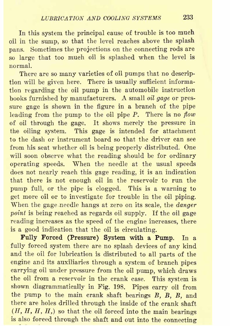
8/9/2019 (1921) Gasoline Automobiles
http://slidepdf.com/reader/full/1921-gasoline-automobiles 245/280
LUBRICATION AND COOLING SYSTEMS 233
In this system the principal cause of trouble is too much
oil in the sump, so that the level reaches above the splash
pans. Sometimes the projections on the connecting rods areso large that too much oil is splashed when the level is
normal.
There are so many varieties of oil pumps that no descrip-
tion will be given here. There is usually sufficient informa-
tion regarding the oil pump in the automobile instruction
books furnished by manufacturers. A small oil gage or pres-
sure gage is shown in the figure in a branch of the pipe
leading from the pump to the oil pipe P. There is no flow
of oil through the gage. It shows merely the pressure in
the oiling system. This gage is intended for attachment
to the dash or instrument board so that the driver can see
from his seat whether oil is being properly distributed. One
will soon observe what the reading should be for ordinary
operating speeds. When the needle at the usual speeds
does not nearly reach this gage reading, it is an indication
that there is not enough oil in the reservoir to run the
pump full, or the pipe is clogged. This is a warning to
get more oil or to investigate for trouble in the oil piping.
When thegage
.needle
hangsat zero on its
scale,the
dangerpoint is being reached as regards oil supply. If the oil gage
reading increases as the speed of the engine increases, there
is a good indication that the oil is circulating.
Fully Forced (Pressure) System with a Pump. In a
fully forced system there are no splash devices of any kind
and the oil for lubrication is distributed to all parts of the
engine and its auxiliaries through a system of branch pipes
carrying oil under pressure from the oil pump, which draws
the oil from a reservoir in the crank case. This system is
shown diagrammatically in Fig. 198. Pipes carry oil from
the pump to the main crank shaft bearings B, B, B, and
there are holes drilled through the inside of the crank shaft
(H, H, H, H,) so that the oil forced into the main bearingsis also forced through the shaft and out into the connecting

8/9/2019 (1921) Gasoline Automobiles
http://slidepdf.com/reader/full/1921-gasoline-automobiles 246/280
234 GASOLINE AUTOMOBILES
under pressure in all the main bearings it insures positive
lubrication in distinction from "hit and miss." Bearings
oiled by this method are likelyto last a
very longtime. The
Fie. 198. Fully Forced (Pressure) System of Lubrication.
oil escapes from the forced system at the edges of the con-
necting rod bearings and is discharged with so much pres-
sure that it is distributed as a fine
spray penetratingto
Pressure Oacje -.,
AdjustablePressure
Ya/ve-
Connecting
RodBearings^
CamshaftBearings
__Reservoir
Oil Pump
FIG. 199. Lubrication System for Eight-cylinder
("Twin Four") Engine.
every part including the pistons, cylinders, and cam shaft
bearings.
This
systemis used in
nearlyall
eight- and twelve-cylinderengines, as well as also in many six-cylinder engines. A
8/9/2019 (1921) Gasoline Automobiles
http://slidepdf.com/reader/full/1921-gasoline-automobiles 247/280
LUBRICATION AND COOLING SYSTEMS 235
Lubrication of Knight Slide Valves. One method of
lubricating the sliding sleeve valves of Knight engines is a
modification of thefully
forcedsystem described, except
that instead of all the oil going through the crank shaft
being sprayed from the ends of the connecting rods, some
of it passes up through a tube inside the connecting rod
to hollow piston pins and from the two open ends of their
pins it flows by gravity over the sleeves and is distributed
through holes and oil grooves over their cylindrical surfaces.
ENGINE COOLING SYSTEMS
Very high temperatures result at the tops of both the
cylinders and the pistons of gasoline engines every time
there is an explosion stroke. At these times the temperature
rises to about 2800 degrees Fahrenheit, a sufficiently high
temperature to make the iron of the cylinder red hot, andall the oil provided for lubrication would be burned up,
if no special means of cooling are provided. The first prin-
ciple of engine cooling is to get the most economical opera-
tion, and this means that the engine should be kept just
cool enough to prevent the cylinder lubricating oil from
burning off the curved surface of the piston. The most
commonly used method of reducing the temperature of gaso-
line engine cylinders is by the circulation of water in an
enclosed space, called the water jacket, which is made a part
of the outside of the cylinder casting, and surrounds also
the valve chambers. By keeping a supply of water passing
through this jacket the engine cylinder can be kept cool
enough to prevent distortion of the metal surfaces as might
result from overheating and to prevent also the burning up
of oil provided for lubrication.
In some engines the water is self-circulating through the
water jackets of the engine cylinders, but in others the
water is pumped so that there is a positive circulation at
alltimes when the engine is runnirig.Air-cooled engines have arrangements to provide un-
8/9/2019 (1921) Gasoline Automobiles
http://slidepdf.com/reader/full/1921-gasoline-automobiles 248/280
236 GASOLINE AUTOMOBILES
the hottest parts of the engine cylinders, which are provided
with ribs or flanges of metal on the outside surface of the
cylinder which are in most cases made as a part of the
cylinder casting. These ribs perform a service similar to
that of the water jacket on other engines. The method
of air cooling circulates air in large volume for cooling the
engine cylinders and the other method circulates water. The
ribs are surrounded by a circular aluminum sheet. The air
spaces between the ribs and this sheet are the only openings
between the top and bottom compartments separated by a
plate. There are fan blades on the flywheel so that it is
used for a suction fan. The cool air enters at the front of
the engine hood into the top compartment, goes down be-
tween the ribs on the engine cylinders and passes out under
the frame of the automobile. The amount of air for each
cylinder is thus mechanically controlled and each gets about
the same amount and with most efficient contact with the
cylinder walls. A good air-cooled automobile uses no more
oil than one that is water-cooled. Air-cooled engines are
usually made of light construction so that they are not
intended for large engine power.
A few makes of automobiles use this method of air cool-
ing, and it is used almost exclusively on all kinds of motor
cycles. The method of air cooling is so simple in principle
that no further explanation is needed.
Pump System of Jacket Water Circulation. Water for
cylinder cooling is circulated through the water jackets of
an automobile engine and its radiator as shown in Fig. 200
by means of a small pump C. The direction of flow of the
water is shown by arrows. The pipes, made usually of flexible
rubber hose, are connected to a cooling vessel, R, called a
radiator. The top hose is connected to a pipe connection at
the top of the radiator, and the lower hose to the bottom of the
radiator. Most water pumps used for this kind of service
are like this one of the centrifugal type, and are operatedby gear wheels driven by the engine crank shaft. They

8/9/2019 (1921) Gasoline Automobiles
http://slidepdf.com/reader/full/1921-gasoline-automobiles 249/280
LUBRICATION AND COOLING SYSTEMS 237
extending out from a central shaft like the spokes of
a wheel. A pump of this kind depends, as its name indi-
cates on centrifugal force and must therefore be operated
at a high speed to be effective. Water enters the pumparound the shaft and is driven outward by the centrifugal
force of the rapid rotation of the blades and discharges from
FIG. 200. Pump System.
a pipe connected to the outside circumference of the pump
casing. The faster the engine runs, the faster the water
circulates.
Another type of circulating water pump is also used. It
consists simply of two small gear wheels which are placed side
Thermostatlc
Valve
FIG. 201. Pump System with Thermostatic Valve.
by side with meshing teeth. These gear wheels are supported
on horizontal bearings in a casing closely fitting the teeth all
around, except at the places at the top and bottom of the
casing where the teeth are in mesh. The water is taken into
the pump at the bottom of the casing and the rotation of the
gear teeth forces it from a discharge opening at the top of
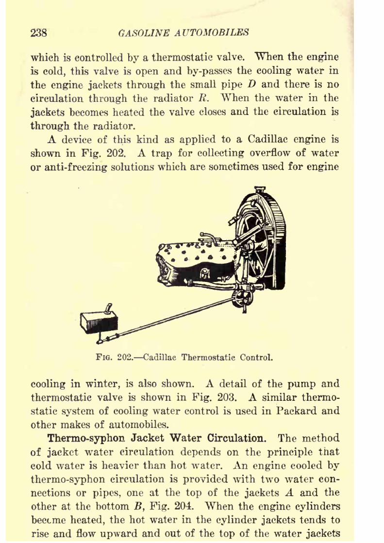
8/9/2019 (1921) Gasoline Automobiles
http://slidepdf.com/reader/full/1921-gasoline-automobiles 250/280
238 GASOLINE AUTOMOBILES
which is controlled by a thermostatic valve. When the engine
is cold, this valve is open and by-passes the cooling water in
the engine jackets through the small pipe D and there is nocirculation through the radiator R. When the water in the
jackets becomes heated the valve closes and the circulation is
through the radiator.
A device of this kind as applied to a Cadillac engine is
shown in Fig. 202. A trap for collecting overflow of water
oranti-freezing
solutions which are sometimes used forengine
FIG. 202. Cadillac Thermostatic Control.
cooling in winter, is also shown. A detail of the pump and
thermostatic valve is shown in Fig. 203. A similar thermo-
static system of cooling water control is used in Packard and
other makes of automobiles.
Thermo-syphon Jacket Water Circulation. The method
of jacket water circulation depends on the principle that
cold water is heavier than hot water. An engine cooled by
thermo-syphon circulation is provided with two water con-
nections or pipes, one at the top of the jackets A and the
other at the bottom B, Fig. 204. When the engine cylinders
become heated, the hot water in the cylinder jackets tends to
rise and flow upward and out of the top of the water jackets

8/9/2019 (1921) Gasoline Automobiles
http://slidepdf.com/reader/full/1921-gasoline-automobiles 251/280
LUBRICATION AND COOLING SYSTEMS 239
is being taken out of the water jackets at the top, cool water
flows in through the bottom hose from the radiator, and this
circulation is automatically maintained as long as the engine
FIG. 203. Cadillac Water Pump and Thermostatic Valve.
cylinders are hot and there is enough water in the radiator
so that the hot water hose from the water jackets to the
radiator contains water. This means that the radiator must
FIG. 204. Thermo-Syphon System.
be kept practically full all the time. If the hot water hose
becomes empty, there will be no circulation, the water in the
water jackets will boil away, and increasing temperatures in
the engine cylinders will interfere with operation. The cir-
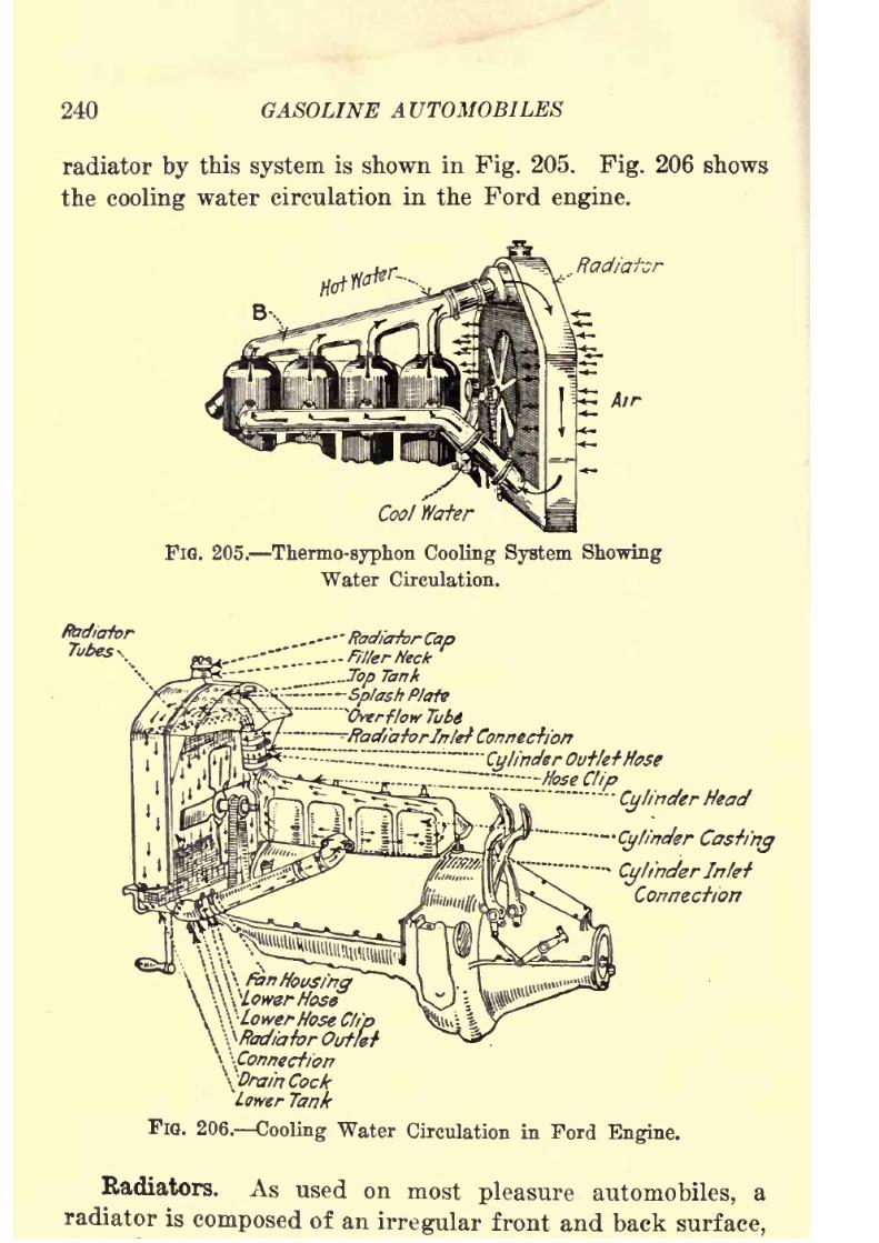
8/9/2019 (1921) Gasoline Automobiles
http://slidepdf.com/reader/full/1921-gasoline-automobiles 252/280
240 GASOLINE AUTOMOBILES
radiator by this system is shown in Fig. 205. Fig. 206 shows
the cooling water circulation in the Ford engine.
Radiator
Air
Cool Wafer
FIG. 205. Thermo-syphon Cooling System Showing
Water Circulation.
______ RadiaforCap
--;.". ..... Filter Neck
_____Top Tank--".-.~
Splash Plate* "Overflow Tube-----
-RadiatorJnlefConnection
-~""~"^\~~"_~~"~~^CylinderOutletHose
-7^-a ..... ,-?!
"...........
Hose Clip
^^5 a-'"'"
-"- .......
r-Qflinekr Head
\'\-Lowerffose Cfip\-Radiator Outlet
.......
Cylinder Casting.
BlinderInle-f'
Connection
\ \Connecfion
\DrainCockLower Tank
FIG. 206. Cooling Water Circulation in Ford Engine.
Radiators. As used on most pleasure automobiles, aradiator is composed of an irregular front and back surface,

8/9/2019 (1921) Gasoline Automobiles
http://slidepdf.com/reader/full/1921-gasoline-automobiles 253/280
LUBRICATION AND COOLING SYSTEMS 241
four inches long which are "flared" or spread out at the
ends E, E, are shown in Figs. 207 and 208. When a number of
these flared tubes areheld
together closely with their ends
\ /'-- Wafer
AirPassages
FIG. 207. Honeycomb Kadiator.
touching and are dipped into a bath B of tinsmiths' solder
as shown in Fig. 209, a bundle of tubes will be made with
square openings, 0, 0, 0. Between the openings there will
FIG. 208. Honeycomb Kadiator with Crimped Tubes.
be very narrow spaces, all communicating with each other.
A large number of these flaring tubes when soldered together
in this way make a typical automobile radiator. As radiators
are set up the flared openings are toward the front of the
automobile for the purpose of having air pass through their
openings to cool the hot water entering the top of the radiator

8/9/2019 (1921) Gasoline Automobiles
http://slidepdf.com/reader/full/1921-gasoline-automobiles 254/280
242 GASOLINE AUTOMOBILES
air circulation is increased by a chain or belt driven fan
placed behind the radiator as shown in Fig. 205 which by its
suctionthrough
theopenings
of the radiatorincreases the
FlQ. 209. Simple Method of MakingEadiator Tubes.
& 'AirSpace
FIG. 210. Zig-Zag Radiator Construction.
amount of cooling air
going through. The narrow communi-cating spaces, 8 (Fig. 209) comprise the principal storage space
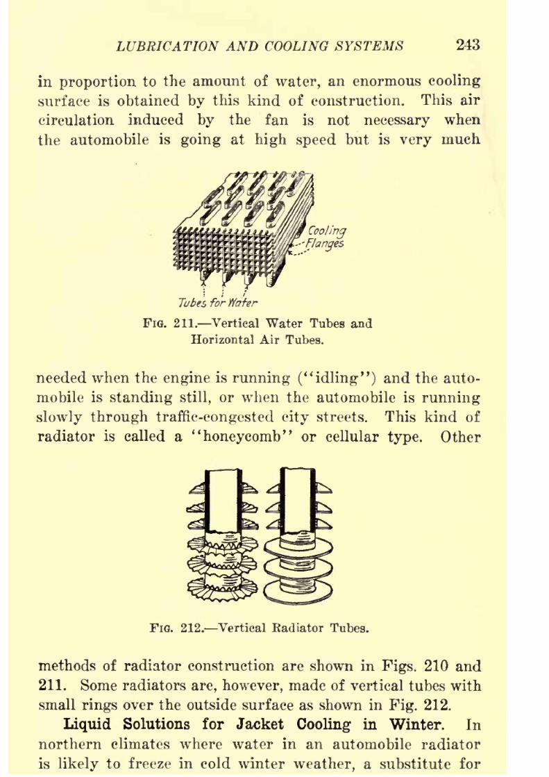
8/9/2019 (1921) Gasoline Automobiles
http://slidepdf.com/reader/full/1921-gasoline-automobiles 255/280
LUBRICATION AND COOLING SYSTEMS 243
in proportion to the amount of water, an enormous cooling
surface is obtained by this kind of construction. This air
circulation induced by the fan is not necessary whenthe automobile is going at high speed but is very much
Cooling
Flanges
Tubes for Wafer
FIG. 211. Vertical Water Tubes and
Horizontal Air Tubes.
needed when the engine is running ("idling") and the auto-
mobile is standing still, or when the automobile is running
slowly through traffic-congested city streets. This kind of
radiator is called a "honeycomb" or cellular type. Other
FIG. 212. Vertical Eadiator Tubes.
methods of radiator construction are shown in Figs. 210 and
211. Some radiators are, however, made of vertical tubes with
small rings over the outside surface as shown in Fig. 212.
Liquid Solutions for Jacket Cooling in Winter. In
northern climates where water in an automobile radiator
is likely to freeze in cold winter weather, a substitute for

8/9/2019 (1921) Gasoline Automobiles
http://slidepdf.com/reader/full/1921-gasoline-automobiles 256/280
244 GASOLINE AUTOMOBILES
ing solutions. The solutions most commonly used are the
following: Denatured alcohol, kerosene, glycerine, and cal-
cium chloride.Denatured Alcohol is in most respects very satisfactory
for mixing with water to make a mixture or solution of
low-freezing properties. The following table gives for
various percentages by volume of alcohol mixed with water,
the corresponding freezing points and specific gravities:
FREEZING POINTS OF COOLING LIQUIDS FOB WINTER USE
Denatured Grain Alcohol Mixed with Water
Per cent by volume Specific gravity Freezing
of alcohol of solution point
10 0.99 24 F.
25 0.97 7 F.
50 0.93 -32 F.70 0.90 -57 F.
Denatured Grain Alcohol and Glycerine (equal parts) Mixed with Water
Alcohol and Freezing
glycerine Water point15 per cent of mixture 85 per cent 20 F.
25 per cent of mixture 75 per cent 8 F.50 per cent of mixture 50 per cent -33 F.
An alcohol and water solution has no destructive effect
on rubber tubing or on any kind of metal. The only dis-
advantage is that it evaporates more rapidly than water,so that in refilling a radiator, it is necessary to add more
alcohol than water in order to keep the solution of a standard
strength. For this replacement mixture the values of specific
gravity given in the above table are convenient.
Kerosene mixed with water makes a very cheap anti-
freezing solution and it does not vaporize readily. In sucha solution the wastage may be safely assured to be all waterunless the kerosene is allowed to
leave the radiator throughthe overflow pipe or through a leak. Kerosene has the great
8/9/2019 (1921) Gasoline Automobiles
http://slidepdf.com/reader/full/1921-gasoline-automobiles 257/280
LUBRICATION AND COOLING SYSTEMS 245
connections and if it is used, the only safe way is to use
radiator connections of some other material than rubber.
Aflexible brass
tubingis
made which has no rubberinser-
tion packing in the flexible folds which can be used. Kero-
sene has the further disadvantage that it does not mix well
with water.
Glycerine has the same disadvantage as kerosene as
regards deteriorating effect on rubber hose connections. It
is, however, very expensive, and sometimes contains acids
which are likely to attack the brass in the radiator. Test
is explained for oils on page 227.
A mixture of twenty per cent by volume of glycerine,
twenty per cent of denatured alcohol, and sixty per cent of
water, gives more satisfactory results than glycerine alone,
as the alcohol has apparently a tendency to reduce the
deteriorating effects of the glycerine on rubber and on the
other hand the presence of the glycerine reduces the vaporiza-
tion loss of alcohol. In the proportions given, this solution
will be safe from freezing at twenty degrees Fahrenheit
below zero.
There are numerous commercially prepared anti-freezing
solutions sold at
highprices. Most of them are made
upof
the liquids mentioned here, although calcium chloride is
favorite material for such solutions. If used at all in radiator
solutions it should be chemically pure. The greatest dis-
advantage from its use is that as the result of evaporation,
a whitish crust will be formed in the water jackets, pipes,
and top of the radiator which has a tendency to clog up
and interfere with good water circulation. This crust is,
however, soluble and can be dissolved when fresh clean
water is put into the radiator and jackets and then heated
by "idling" the engine with retarded "spark." Calcium
chloride solutions should be te'sted for acidity as suggested
for glycerine. Commercial calcium chloride (not chemically
pure)is
almost certain to set up electrolytic action whentwo kinds of metals are joined together, as for example,
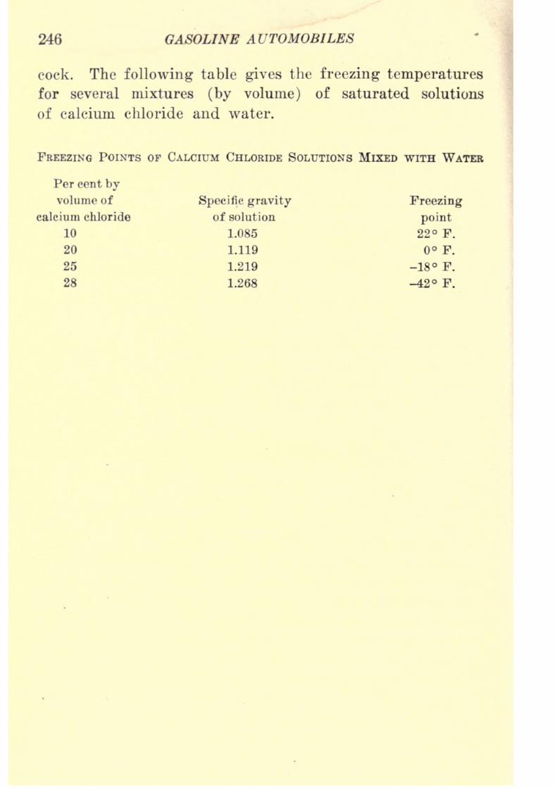
8/9/2019 (1921) Gasoline Automobiles
http://slidepdf.com/reader/full/1921-gasoline-automobiles 258/280
246 GASOLINE AUTOMOBILES
cock. The following table gives the freezing temperatures
for several mixtures (by volume) of saturated solutions
of calcium chloride and water.
FREEZING POINTS OF CALCIUM CHLORIDE SOLUTIONS MIXED WITH WATER
Per cent by
volume of Specific gravity Freezing
calcium chloride of solution point
10 1.085 22 F.
20 1.119 F.
25 1.219 -18 F.
28 1.268 -42 F.
8/9/2019 (1921) Gasoline Automobiles
http://slidepdf.com/reader/full/1921-gasoline-automobiles 259/280
CHAPTER X
AUTOMOBILE TROUBLES AND NOISES
Modern automobiles have been perfected to such a degree
by high engineering skill in both mechanical and electrical
work that the troubles and noises now occurring are indeed
few in number compared with the automobiles made several
years ago. In this connection it is worth while noting that
dealers in second-hand cars, who decide their buying points
for an automobile by the amount of noise it makes when
running make their prices on more than a little basis of
fact. The noise an automobile makes is a fairly good indexto its condition as to wear, repair, care in operation, lubrica-
tion, etc. Many automobiles that are four or five years
old but have been carefully used and kept in good repair
are as free from noises as some cars that have been operated
only a few months, and their serviceableness for future use
is correspondingly large.
Carbon Deposit in the Cylinders is probably the most
common cause of trouble in automobile operation. It is
always the result of the imperfect combustion (1) of engine
oil which gets to the top of the cylinders, past the piston
rings or (2) of gasoline which has not mixed in the right
proportions with the air supply or (3) the mixture of gaso-
line vapor and air has not been completely ignited on every
power stroke because of imperfect spark plugs or other
defects in the ignition apparatus. The remedy is to clean
out the carbon. The easiest way to get an idea as to the
condition of an engine cylinder as to carbon deposits is to
take out a spark plug. If there is enough carbon deposit
in one or more of thecylinders,
there will be apeculiar
"pounding" of the pistons due to particles of red hot carbon
8/9/2019 (1921) Gasoline Automobiles
http://slidepdf.com/reader/full/1921-gasoline-automobiles 260/280
248 GASOLINE AUTOMOBILES
The "pounding" therefore is the same kind of noise heard
when the spark is advanced too far or with a heavy load
going upa grade, the spark is not retarded. If the
plughas been in that particular cylinder for some time and has
a considerable coating of carbon on the porcelain or mica
center piece, it is to be assumed that the walls and exhaust
valve are also coated and need cleansing. The best way
to remove carbon deposits is to have it burned out at a
repair shop with oxygen-acetylene flame apparatus. Another
method is by scraping off the carbon deposits by the use
of tools of slightly different shapes which are bent so that they
will reach into and scrape over the end of the piston and
the walls of the cylinder. The usual method is to scrape
all the loose carbon to the exhaust valve and when the work
of scraping is finished, turn the engine by hand till the
exhaust valve is opened wide when the carbon refuse canbe pushed into the exhaust pipe, and when the engine is
started it will be discharged with the engine exhaust. It
is recommended that after finishing with the scraping tools,
that a small brush be used to remove all loose particles and
that finally a little kerosene be poured into the cylinders
to serve as a "wash." When through, examine the exhaust
valve and its seat carefully to be certain no particles of
carbon remain attached which would interfere with proper
closing. It is a good idea to make a paste of flake graphite,
finely powdered, and "cup" grease for use on the threads
of the cylinder plugs over the valves. When replacing the
plugs, be sure the copper gaskets or "washers" are put
in under the plugs, as putting these, together with usingthe graphite paste on the threads is good insurance for tight
joints. The same precautions as to tightness of joints should
be observed whenever replacing spark plugs. Whenever
greasy spots are observed around valve plugs, it is an indica-
tion of loose joints, which are always wasteful of power and
prevent getting the natural pressure on the
compressionstroke necessary for best efficiency. The use of copper gas-
8/9/2019 (1921) Gasoline Automobiles
http://slidepdf.com/reader/full/1921-gasoline-automobiles 261/280
AUTOMOBILE TROUBLES AND NOISES 249
When examining spark plugs to test for the presence of
carbon deposits, it may be observed that in some cases the
depositis
veryblack
stickysubstance which adheres firmly
to knives and tools. This kind of deposit is an indication
always of an excessive amount of engine oil getting past
the piston rings and finding its way into the cylinder. It
may be that most of the carbon in such case is deposited
because of improper mixtures from the carbureter of gaso-
line and air, but in any event the excess of oil is the cause
of part of the deposit. On the other hand, if the carbon
deposit is dry and brittle it is likely to be due almost entirely
to improper mixtures of gasoline and air, to the same cause
as that producing thick black smoke in the discharge from
the engine exhaust pipe.
Kerosene put into the engine cylinders in small quan-
tities, about two or three tablespoonfuls at a time, will, inmost cases, remove small carbon deposits, and if used
regularly, say once a week, may prevent further trouble
from this cause. It can be put into the cylinders most easily
by fitting the little cups on the priming cocks or by squirting
into the main air valve of the carbureter from small (com-
pression bottom) oil can, just before the engine is stopped.
When kerosene is put into the cylinders by either method,
the engine should not be run again for several hours, and
when it is started there should be thick black clouds of
smoke coming from the exhaust, indicating that carbon has
been removed. Another method sometimes used is to run
the engine for about fifteen minutes once a week, with
the spark well retarded as for starting, and inject kerosene at
the air inlet of the carbureter, with the float valve of the
carbureter held down and closed.
Grinding the Valves. It is a good plan to grind the
exhaust* valves of the engine at the same time that the valve
*
The intake valves make less trouble than the exhaust valves because
through them passes cool, fresh, unburned mixtures, while through the
8/9/2019 (1921) Gasoline Automobiles
http://slidepdf.com/reader/full/1921-gasoline-automobiles 262/280
250 GASOLINE AUTOMOBILES
plugs are removed for the removing of carbon either by
burning or by scraping. When the pressure on the com-
pression stroke is less than it should be, it is most often
the result of leaky exhaust valves, which do not close tightly
on the compression stroke, because of the lodgment of
particles of carbon and therefore permit leakage through
them.
Valve grinding begins with the removal of the valve
plugs on the cylinders requiring valve grinding. Next the
spring (see Fig. 173) on the valves must be removed so
that the valves can be turned. Then lift the valves for
grinding and put a thin coating of grinding paste on the
bevel (conical) part of the valve. A satisfactory paste can
be made of powdered emery mixed with enough kerosene
to make a thick paste and then add a few drops of oil in
theproportion
of about onedrop
toeach tablespoonful
of
kerosene used. Exact proportions are, of course, not essen-
tial. It is best to make two kinds of this paste, one with
rather coarse emery for rough cutting and another with
very fine emery to give a smooth, clean surface for finishing.
Valve grinding pastes, mixed for use, can be purchased at
most automobile supply stores.
After these preliminary operations, a special valve grind-
ing tool, a carpenter's brace with attached screw-driver or
a plain hand screw-driver may be used for the grinding.
The tool or screw-driver fits into a notch like the head of
a screw in the top of the valve. The grinding is done by
rotating (oscillating) the valve back and forth until the
entire bearing surfaces of both the valve and its seat aremade clean and smooth. The valve should not be turned
all the way round, as one would bore a hole with a brace,
but should be rotated only about a quarter turn with light
pressure. Now and then the valve should be lifted, turned
half way round while the grinding is continued. This turn-
ing is for the purpose of getting good seating of the valve
in all positions, as without the turning it might fit well
in one

8/9/2019 (1921) Gasoline Automobiles
http://slidepdf.com/reader/full/1921-gasoline-automobiles 263/280
AUTOMOBILE TROUBLES AND NOISES 251
After the valve grinding is finished, the valve, its seat,
and its guide-rod should be well washed in gasoline,
so that none of the emery paste remains to scratch the
surface of the valve as it operates. To test the work to
see that it is well done, put a narrow lead pencil line all
the way round the bevel edge of the valve and turn the
valve all the way around several times. If the line is rubbed
out over the whole circumference the valve is likely to be
satisfactorily tight.
"Knocking" or "pounding" in the engine cylinders may,
in addition to the causes already mentioned, such as red-hot
particles of carbon deposit, or an excessively hot engine
igniting the explosive mixture before the spark is made, spark
being too far advanced for the speed and kind of load, also
be caused by loose connecting-rod bearings, loose piston
wrist-pins, and loose crank shaft bearings, all of which
are in most cases due to overheated bearing surfaces caused
by insufficient lubrication. Infrequently, however, it is also
caused by the engine getting too hot on a warm day, when
heavily loaded, or because of a loose piston or broken piston
ring. Trouble with bearings such as are listed here are best
remedied by a skilled mechanic. Amateurs who are not
well experienced are likely to make bearings much too
tight after having them apart for repairs and there is unend-
ing trouble until the bearings get either "worn in" or
"burned out."
A rhythmic "knocking" is also caused by "missing"
cylinders, meaningthat the
engine cylinderor
cylindersmaking the noise are not firing the explosive mixture they
are receiving. This is a different sound from the knocking,
due to loose bearings or to too early ignition, and further,
if only one cylinder is missing the sound will be heard only
once in a revolution. It is less observable in engines of
eight or twelve cylinders than in those or four or six
cylinders. It is usually due to a sooted, defective, or broken
be caused a broken electric

8/9/2019 (1921) Gasoline Automobiles
http://slidepdf.com/reader/full/1921-gasoline-automobiles 264/280
252 GASOLINE AUTOMOBILES
"Tapping" valve rods are another source of trouble. The
"tapping" of valve rods does not indicate that there is any-
thing seriously wrong with the engine. It will continue
to give approximately its full power at about the usual
gasoline consumption. It is merely an annoying noise com-
parable with squeaking of springs or the rattle of doors.
The "tapping" noise is caused by gradual wearing away of
the bevel faces of valves or of their seats. When the
valve stems are properly adjusted with respect to the pushrod on the side shafts carrying the cams for opening the
valves, there is a little space, clearance, between the bottom
of the valve stem in the closed position and the top of the
adjusting screw on the push rod. When properly adjusted,
the space between the bottom of the valve stem and the
top of the adjusting screw is not much more than the
thickness of a sheet of good letter paper. It should
be noted that there is much more likelihood of getting poor
engine results if the clearance is made too large when adjust-
ing than there is likely to be from any wear in the direction
producing valve tapping. Adjust carefully therefore to see
that the clearance is not made too large, because if it is
too large, the push rod does not lift the valve the full
amount, cutting down both the height the valve is lifted
and also the time it is open. Of course one could imagine
the condition where the valve stem and the top of the push
rod would wedge each other so closely (no clearance) that
the valve could not in any position get down on its seat.
This would beespecially
bad in thecompression stroke,when the explosive mixture in the cylinder must be put
under pressure by the upward stroke of the piston. If
either the exhaust valve or the inlet valve does not close
properly, the necessary pressure for efficient combustion
cannot be obtained.
Some authorities claim that a weak spring on the exhaust
valve can be a cause of poor engine economy. The effect
produced is that the exhaust valve because of the
8/9/2019 (1921) Gasoline Automobiles
http://slidepdf.com/reader/full/1921-gasoline-automobiles 265/280
AUTOMOBILE TROUBLES AND NOISES 253
for sucking in the explosive mixture from the carbureter,
and that some of the burned gases from the previous power
stroke will be sucked into the cylinder from the exhaust
pipe. Recent experiments, however, show that the efficiency
of combustion is actually improved by the mixing of a small
amount of the burned gases with the fresh charge.
Valve Timing and Setting are properly the work for only
good experienced mechanics. Instruction books prepared
for andgoing
with the different kinds of
automobiles,ex-
plain the method for each kind of engine in detail, with
the help of marks of various kinds on the flywheel, on
pointers, and on timing gears. The principles have been
explained in the various preceding chapters.
Wrong Explosive Mixtures are the result of incorrect
proportions of gasoline vapor and air in mixture sucked into
the engine cylinders from the carbureter.
Flooded Cylinder. The most troublesome condition is
when the mixture in the cylinder is much too rich in gaso-
line, so that it will not explode. Most often this is caused
when the engine is turned over a number of times, either
by hand or with a starter, and because of temporarily defec-
tive ignition there are no explosions. As a result, thereis an accumulation of drops of gasoline, on the inside of the
cold cylinders, which have separated from the mixture, most
of which, of course, goes out through the exhaust pipe. This
accumulation of drops of gasoline is rapid, because for start-
ing, especially in cold weather, mixtures very rich in gaso-
line are used. In this way it is easy to get a mixture so
largely gasoline that it cannot explode even when the tem-
porary difficulty with the ignition is corrected. The simplest
remedy is to open the priming cocks on all the cylinders
and continue to turn the engine over a number of times, so
that on the compression strokes the mixture, excessively
saturated with gasoline will be driven out through the open-
ings in the cocks. If this condition in the cylinder is very
bad, the gasoline vapor may be seen at the discharge open-
8/9/2019 (1921) Gasoline Automobiles
http://slidepdf.com/reader/full/1921-gasoline-automobiles 266/280
254 GASOLINE AUTOMOBILES
are again closed, the engine will usually start after a few
turns of cranking.
Flooded Carbureter. Somewhat similar results to those
explained above result from getting the carbureter thor-
oughly wetted inside with liquid gasoline. Some people
are in the habit of always manipulating the float valve on
the carbureter by hand to make starting easier. This is
called "priming the carbureter" with the object of getting
an excessively rich mixture. Not infrequently this car-
bureter manipulating is done a few times too often when
there is some temporary trouble with ignition, so that by
the time ignition trouble has been corrected the mixture
going into the cylinders from the carbureter has too much
gasoline to be exploded. There are two simple remedies:
(1) by cranking with priming cocks open as for flooded
cylinder; or (2) by not doing any more cranking for about
ten or fifteen minutes, after which time the excess of gaso-
line in the carbureter passages will probably be evaporated,
so that cranking will then start the engine without difficulty.
Test for condition of carbureter flooding by putting a finger
into the air inlet tube.
Sometimesit
happens that a bit of rubber or of woodgets under the float valve of the carbureter. At one time
this was a common carbureter trouble but does not occur
so frequently now since so much gasoline is purchased from
reliable dealers who know enough to avoid the use of hose
connections on gasoline filling machines which contain rub-
ber or rubber compounds. A particle of rubber or other
foreign material when stuck in the float valve may cause
continued cylinder and carbureter flooding. The obvious
remedy is to remove the cause. Sometimes it can be removed
by shaking the float valve, but usually it is necessary to
take the carbureter apart. Now, a word of caution ! Unless
circumstances are unusually urgent, do not spoil the adjust-
ments of a good carbureter by taking it apart unless besides
knowing all about the theory of the carbureter, you have
8/9/2019 (1921) Gasoline Automobiles
http://slidepdf.com/reader/full/1921-gasoline-automobiles 267/280
AUTOMOBILE TROUBLES AND NOISES 255
carbureter used. The level at which the float must be set
is always determined by experiment and inexperienced per-
sons will usually do a great deal of experimenting before
they get even reasonably satisfactory adjustments.
Carbureter flooding results also sometimes from the float
losing its buoyancy by filling with gasoline. If a cork float
is used in the carbureter, partial loss of buoyancy is not
unusual. The effect is to make the float heavier than it was
when originally adjusted with respect to the float valveand will permit the gasoline to stand higher in the gasoline
or float chamber than was intended. High gasoline level maymake gasoline stand in the orifice tube so high that it might
be overflowing continually, whether or not the engine is
running. The remedy is to take out the cork float and after
drying, paint it with shellac. Baking in a shellac baking
oven is desirable if equipment of this kind is available.
If the float is of the hollow metal kind, the loss of
buoyancy is due to holes in its surfaces. The remedy is to
empty and dry the float and then close the hole or holes
with solder. Floats should always be carefully tested for
buoyancy for several hours before they are put into place
in the carbureter.
Color of Flame from Priming Cocks. In this connection,
it is interesting to observe that the color of the flame from
open priming cocks is a good indication of the correctness
of the proportions of the explosive mixture in the engine
cylinders. If the mixture is of satisfactory proportions to
givemost effective
explosions,the flame has a bluish color.
When the flame is tinged strongly with red, the mixture is
too rich in gasoline ;and when it has a whitish color it is
much too weak in gasoline.
Back-firing into the Carbureter. Most modern automobile
engines are designed so carefully that there is little trouble
with back-firing into the carbureter (see page 101) except
when the mixture going into the cylinders is too weak. Weakmixtures be due to incorrect of the

8/9/2019 (1921) Gasoline Automobiles
http://slidepdf.com/reader/full/1921-gasoline-automobiles 268/280
256 GASOLINE AUTOMOBILES
so that there is not enough to maintain the proper level in
the carbureter for a sufficiently strong mixture.
A weak mixture from the carbureter at low engine speeds
is usually due to too little gasoline in the mixture (float
valve set too low) ;and when the mixture is too weak only
at high speeds it is due to too much air through the auxiliary
air valve (auxiliary air spring too weak).

8/9/2019 (1921) Gasoline Automobiles
http://slidepdf.com/reader/full/1921-gasoline-automobiles 269/280
INDEX
Advance of spark, 125, 129, 165
Air cooling, 235
Alcohol for fuel, 50, 51
in radiator, 244
Alternating current, 112, 168
rectifier, 112, 113
Ampere, 105
Aniline, 53
Armature, 149
Atwater-Kent ignition, 144
Automatic gear shifts, 221
Automatic spark advance, 125, 142
, Delco, 125
,North East, 142
Automobiles, electric, 3
, gasoline, 4
, steam, 2
, types of, 2, 4
Axle drive shaft, 9, 208, 211
Axles, front, 13, 14, 203
,live, 211
, rear, 9, 11, 206, 211
Back-firing, 255
Batteries, dry, 105
, storage, 106
Battery charging, 107, 177
connections, 115
ignition, 12x
troubles,110
Baume hydrometer, 54
Benzol, 51
Bevel gear drive, 207, 210
Block cylinders, 44
Bodies, types of, 4, 5, 8
Bore, cylinder, 45
Bosch magneto, 156
battery ignition system, 147
Brakes, 10, 218
, adjustment of, 219
, equalizers, 218
, failures, 220
Braking with engine, 219
Burton process, 49
Cabriolet, 5Cadillac cooling system, 238
Calcium chloride, 246
Camber of front wheels, 205
Cam shafts, 26
Carbon deposits, 103, 247
Carbureter adjustments, 101, 103
, auxiliary air valve, 67
troubles, 100-103
priming, 69
Carbureters, 63-103
, Cadillac, 93-94
, Holley, 80-81
, Johnson, 89-90
, Kingston, 73-75
, Marvel,75-76
, Packard, 94, 98-100

8/9/2019 (1921) Gasoline Automobiles
http://slidepdf.com/reader/full/1921-gasoline-automobiles 270/280
258 INDEX
Carbureters, regulated nozzle, 70
, Schebler, 82-83, 91-92
, Stewart, 79-80
, Stromberg, 77-78
, Tillotson, 89
, Zenith, 87-88
Cars, (See Automobiles)
Cells, (See Batteries)
Chain drives, 170
Change gears, 9, 12, 188
Chargingbatteries, 107, 177
Chassis, 8
Clearance, 48
Clutches, 9, 11, 28, 184
Coils, vibrating, 127, 131
, non-vibrating, 136, 138
Color of exhaust, 102, 255
Compression, 25, 50
Condensers, 130, 136, 142Cone clutches, 185
Connecticut ignition system, 124,
143
Connecting rod, 23
Cooling systems, 235
solutions, 243
Coupe, 4-6
Cracking gasoline, 49
Crank case, 23
Crank shafts, 9, 34, 46, 47
Cycles, 23
, four, 23-28
,two, 23
Cylinder arrangements, 28, 36
cooling,235
oils, 226, 227
Cylinders, engine, 9, 28, 44
Dash control, 83
Delco ignition, 126, 140
starter, 170, 173
Detachable cylinder head, 45
Differential gear, 10, 207
Dimming resistance, 138, 182
Direction of current, 114, 115
Disk clutch, 186
Displacement, piston, 48
Distributor, 122, 163
Distributing arm, 122
Doped gasoline, 51
Double ignition, 158
Drag link, 204
Drive, Hotchkiss, 218
shaft, 9, 208
Dry cells, 105
Dual ignition, 158
Electric automobiles, 3
starters, 167-183
Engine, 9, 19, 21-48
as brake, 219
, Cadillac, 41
-- cycles, 23
cylinders, 44, 45
, Dodge, 44
, Ford, 159
, four-stroke, 23-28
horse power of, 47
, Knight, 30
, Packard, 42
speeds, 36
, two-stroke, 23
Exhaust gases, 22
Explosive mixture, 21, 22
force, 22, 25
Feed systems, gasoline, 56
Fire (gasoline), 70
Fire test foroils,
227
Firing order, 45
Flash point of oils, 226
Flow of power, 7, 38, 39
Flywheels, 8, 28
Forced feed oiling, 233
Ford axle, 211
cooling system, 240
engine, 159
ignition system, 133

8/9/2019 (1921) Gasoline Automobiles
http://slidepdf.com/reader/full/1921-gasoline-automobiles 271/280
INDEX 259
Ford planetary gears, 199
rear axle, 209
timer, 134
transmission, 199-203
Four-stroke engine, 24
Frames, 9, 14, 15
Franklin, air cooling, 235
Friction, 223
clutch, 9, 11, 28, 184
Front axle, 13, 14, 203, 205
Fuelizer, Packard, 98-100Full floating rear axle, 213
Gasoline, 49-51
and benzol, 51
carbureters, 63-103
, doped, 51
, heating value of, 55
mixtures,
50
substitutes, 49-51
tanks, 56
Gears, differential, 10, 207
, planetary, 190, 197
t progressive sliding, 190
,selective sliding, 190
, speed-change, 9, 12, 188
Glycerine for cooling, 245
Gravity feed system, 61
Greases, 227
Grinding valves, 249
Head, detachable cylinder, 45
Head lights, 182
Heating value of gasoline, 55
High-tension magneto, 151
Holley carbureters, 80
Honeycomb radiator, 241
Horse power formulas, 47, 48
Hot air connection, 83, 96
Hot spot on manifold, 95, 96
Hot water connection, 86, 97
Hotchkiss drive, 218
Hydrometer, battery, 111
, Baume, 54
Idling, 86, 88
Ignition, 104-147
systems, 121, 138-147
troubles, 161-166
Insulators, electrical, 105
Intake manifold, 42, 94
valve, 25
Kerosene, 244, 249
King bolts, 204
Kingston carbureter, 73
Knight engine, 30-31
, oiling, 235
slide valves, 30-31
Knocking in cylinder, 52, 251
Leaves of springs, 15
L-head cylinder, 28
Limousine, 5
Low-tension magneto, 151
Lubricants, 225
Magnetism and electricity, 116
Magneto adjustments, 160
armatures, 149
,
Bosch,
156
,care of, 160
, Dixie, 150
,Ford, 157
timing, 160
troubles, 161-164
Magnetos, 148-161
, high- and low-tension, 151
Magnets, demagnetized, 161
Manifolds, intake, 42, 94
Marvel carbureter, 75-76
Master vibrator, 135
Mixtures, explosive, 21, 22
,rich, 101, 102
,weak or lean, 101
Motors, (See Engines)
, starting, (See Starters)
Mufflers, 10
8/9/2019 (1921) Gasoline Automobiles
http://slidepdf.com/reader/full/1921-gasoline-automobiles 272/280
260 INDEX
Non-vibrating induction coil', 136,
138
North East ignition, 141
starter, 177, 179
Oiling, (See Lubrication)
Oil pumps, 231
Oils, cylinder, 226, 227
Over-running clutch, 172
Packard fuelizer, 98
Parallel battery connections, 116
Peened piston rings, 33
Pistons, 22, 32, 41, 42
Piston displacement, 48
rings, 32
Planetary gears, 190, 197
Plugs, spark, 24, 25, 119, 161, 165
Powerdiagrams,
39
Power, horse, 47, 48
plant suspension, 43
Pressure feed systems, 61
Primary coil, 119
Priming carbureters, 69
Progressive sliding gears, 190, 192
Eadiators, 9, 240
Eadius rods, 217
Kayfield carbureter, 85
Bear axles, 9, 11, 206, 211
Rectifier alternating current, 112,
113
Kemy ignition, 145, 147
Resistance, electrical, 104
Eeverse current cut-out, 174
speed-change gears, 191
Eittman process, 49
Eoadster, 5
S. A. E. horse power formula, 47,
48
Safety resistance, 123spark gap, 155
Secondary coil, 119
Sedan, 5, 6
Selective sliding gears, 190, 192
Semi-floating rear axle, 211Series battery connections, 115
Shafts, cam, 26
, crank, 9, 34
, drive, 9, 208
Shifting gears, 13
lever, 195, 197
Shock absorbers, 220
Short circuit, 105
Slide valves, 29-31
Smoke from exhaust, 102
Spark advance, 125, 129, 165
coil, 132, 133
plugs, 24, 25, 119, 161, 163, 165
Specific gravity, 55
Speed-change gears, 9, 12,188
Speeds, engine, 36
Spiral bevel gears, 210
Splash oiling system, 230
Springs, 14-19
Starter-generator, 167
Starters, 167-183
,Delco, 170, 173, 177, 179
, electric, 167-183
, Liberty (for Ford), 180
,North East, 177, 179
, Westinghouse, 177, 179, 180,
181
Starting in cold weather, 182
motor drives, 169
motor troubles, 182
Steam automobiles, 2
Steering gear, 13, 203
knuckle, 203, 228
Stewart carbureter, 79
vacuum feed system, 56-60
Stopping, 12
Storage battery, 106, 107
, charging, 107, 112, 114hydrometer, 111

8/9/2019 (1921) Gasoline Automobiles
http://slidepdf.com/reader/full/1921-gasoline-automobiles 273/280
INDEX 261
Storage battery, refilling with aeid,
108
, sulphating, 109
Stromberg carbureter, 77-78
Testing electric wires, 114, 115
T-head cylinder, 28.
Thermostatie cooling system, 237
Thermo-syphon cooling, 238
Three point motor support, 43
Third brush regulation, 176
Tillotson carbureter, 89
Timers, 129
Timing, magneto, 160
Tires, 10, 206, 208
Torque members, 217
Transmission gears, 13, 188
(See also Speed-change gears)
, planetary, 190, 197
Two-cycle engines, 23
Two-stroke engines, 23
Two unit starting system, 179
Universal joints, 13, 214
Vacuum gasoline feed, 56-60
Valve stems, 26
-in-the-head, 29
Valves, adjustment of, 253
, arrangement of, 28
, grinding, 249
, Knight sliding, 30
, needle, 71
, timing, 253
Vibrating induction coil, 127, 131
Vibrator, 127, 135
Volt, definition of, 104
Voltage, constant, 180
Voltage of dry cell, 105
of spark, 119
storage cell, 175
Water-cooling systems, 236
Westinghouse ignition system, 143
starters, 177, 179, 180, 182
Wheel alignment, 205
Winter cooling solutions, 243
Worm differential gear, 210
Worm steering gear, 203, 205
Zenith carbureter, 87.

8/9/2019 (1921) Gasoline Automobiles
http://slidepdf.com/reader/full/1921-gasoline-automobiles 274/280

8/9/2019 (1921) Gasoline Automobiles
http://slidepdf.com/reader/full/1921-gasoline-automobiles 275/280

8/9/2019 (1921) Gasoline Automobiles
http://slidepdf.com/reader/full/1921-gasoline-automobiles 276/280

8/9/2019 (1921) Gasoline Automobiles
http://slidepdf.com/reader/full/1921-gasoline-automobiles 277/280

8/9/2019 (1921) Gasoline Automobiles
http://slidepdf.com/reader/full/1921-gasoline-automobiles 278/280
18
University of California
SOUTHERN REGIONAL LIBRARY FACILITY
305 De Neve Drive -Parking Lot 17 Box 951388
LOS ANGELES, CALIFORNIA 90095-1388
Return this material to the library from which it was borrowed.

8/9/2019 (1921) Gasoline Automobiles
http://slidepdf.com/reader/full/1921-gasoline-automobiles 279/280
UC SOUTHERN REGIONAL LIBRARY FACILITY
Illllllll Hill Illll Illl
A 001415273 o

8/9/2019 (1921) Gasoline Automobiles
http://slidepdf.com/reader/full/1921-gasoline-automobiles 280/280