332 the design of shallow habitat sewer … · 2014-03-07 · the design of shallow sewer systems...
TRANSCRIPT

332
HABITAT
THE DESIGN OF SHALLOWSEWER SYSTEMS
‘t •)•)- -s-./332—39642
1 •

THE DESIGN OF SHALLOWSEWERSYSTEMS
United Nations Centre for Human Settlements (Habitat)
UBRARY, INTERNATIONAL REFERENCECENTRE FOR GOMMU~JTYWATER SUPPLYAND SAN~r~CN~1RC)RO. Bo~93~O, 2~O1)AD The Hagu.Tel. (070) 8~4911 cxt. 141/142
3~L1
~32-Z
(2rd~~)
Nairobi 1986

HS/100/86/E
ISBN 92—1—131019—9

FOREWORD
The importance of providing safe and adequate water supply andsanitation has gained increasing international attention over the lasttwo decades. The concern of national and international organizationswith the gross shortfall in the delivery of basic services, especiallyto the low—income urban and rural poor, was expressed at Habitat:United Nations Conference on Human Settlements, held at Vancouver,Canada, in 1976. Subsequently, the United Nations Water Conference,held at Mar del Plata, Argentina, in 1977, recommended that the period1981-1990 be designated International Drinking Water Supply andSanitation Decade. The Decade was launched by the General Assembly on10 November 1980 at a one-day special meeting during its thirty -fifthsession. In its resolution 35/18 of 10 November 1980, the GeneralAssembly stated that during the Decade, Member States would assume acommitment to bring about a substantial improvement in the standardsand levels of services in drinking water supply and sanitation by theyear 1990. The United Nations Centre for Human Settlements (Habitat)is actively collaborating with other United Nations agencies inassisting national governments to achieve the objectives of thedecade. UNCHS (Habitat) was directed by the Commission on HumanSettlements, in its resolution 4/16 of 6 May 1986, to embark on a workprogramme to assist developing countrieè in the provision of adequateinfrastructure in low-income communities. The work programme definesa role for UNCHS (Habitat) which would comple-ment the activities ofother United Nations agencies and take advantage of the particularstrengths of UNCHS (Habitat) in information transfer, training anddemonstration projects.
The effects and initiatives of many international agencies, inparticular the World Bank, has led to the identification of a numberof technologies for sanitation which are less costly than waterbornesewerage, yet able to provide the same health benefits and be bothsocially and environmentally acceptable to the users. A majority ofthese technologies rely on the on—site disposal of human wastes.Space for such disposal facilities is usually available in rural andlow-density to middie-density urban areas. Their use in high-densityurban areas, which are being increasingly supplied with water—distribution services, is limited. Unfortunately, the bulk of slumand squatter-settlement housing in the cities of developing countriesis high-density and very few options are available for providing low-cost waste disposal facilities to these communities. Recently,however, the shallow sewer system of sanitation has emerged as aresult of adapting design standards to Buit the physical conditions ofa majority of these low—income settlements and taking advantage ofadvances in knowledge on the mode of operation of sewer systems.
This technical manual sets out criteria, standards and proceduresfor designing and constructing shallow sewer systems. They are oom-pared with other sanitation technologies, and the conditions underwhich they are considered to be particularly advantageous to low—income communities are established. Strategies for implementingshallow sewer systems, so as to promote the technology and provide abasis for comparing the cost of different sanitation technologies, arepresented, together with methods of determining communityaffordability. Case studies of successfully implemented shallow sewersystems, including one executed by UNCHS (Habitat), are alsoconsidered. Finally, the manual presents a shallow sewer designexample.

The manual is specifically designed to demonstrate technologythat lends itself to application in low-income settlements andpresents some novel approaches and institutional changes which haveyielded positive resuits in the continued bid to narrow the deficit inthe provision of urban services to poor communities. For thesereasons, the manual has a special significance for the efforts of theInternational Year of Shelter for the Homeless (IYSH) which, amongstits various objectives, seeks to provide basic services to deprivedcommunities. The programme, scheduled for 1987, recognizes theimportance of the role that basic infrastructure can play in assistingthe millions of poor all over the world to build and improve theirshelter and neighbourhoods and, by go doing, to integrate them in theprocess of economie development.
Dr. Arcot RamachandranUnder—Secretary-General
Executive Director

CONTENTS
Page
FOREWORD
INTRODUCTION 1
A. Background 1
II. The problem of sanitation as it relates to
human settlements in developing regions 1C. Purpose and scope of the manual 3
D. Acknowledgements 4
1. CHARACTERISTICS OF SHALLOW SEWERAGE 5
A. System description 5
B. Mode of operation 5
C. System advantages 7
D. Component parts 9
E. Applicability in developing countries 13
II. SHALLOW SEWER DESIGN CRITERIA AND SPECIFICATIONS .. .18
A. Design considerations 18
B. House connections 18
C. Common block and street collector sewer 19
D. Appurtenances 26
III. SHALLOW SEWER PLANNING AND IMPLEMENTATION STRATEGIES 36
A. Project area and drainage basin 6
B. Physical surveys 36
C. Sample socio—economic survey 37
D. Institutional requirements 37
E. Community involvement in construction ofshallow sewers 38
F. Worker requirements 40
G. Project drawings 41
IV. CONSTRUCTION AND MAINTENANCE OF SHALLOW SEWERS 42
A. Block and street sewer installation 42
—1—
8. Inspection chamber installation 47
C. As-constructeddrawings 48
D. Maintenance of shallow sewers 48
V. PROJECT COSTS, APPRAISAL AND AFFORDABILITY 50
A. Project costs 50
B. Project appraisal 52
C. Affordability 55
VI. CASE STUDIES 60
A. Rocas and Santos Reis, Natal, Brazil(two spontaneous squatter settlements) 60
B. Planned low—income housing schemesin the State of Rio Grande do Norte, Brazil .. . .63
C. Orangi, Karachi, Pakistan(spontaneous squatter development) 64
NOTES 70
Annexes
1. Shallow sewer design example 73
II. Tables for the hydraulic design of pipes 82
List of tables
1. Descriptive comparison of sanitation
technologies 14
2. Inspection chamber dimensions 35
3. Nature of skills required to executevarious activities related to shallow sewerplanning and construction 40
4. Approxjmate trench widths for different pipedepths and diameters 45
5. Construction work associated with houseconnections 51
6. Construction work associated with blockand street sewers 51
7. Total annual- (economic) costs per householdof different sanitation technelogies 54
— ii —

8. Percentage investment and recurrent costof community sanitation systems 55
9. Financial costs per househoids ofdifferent sanitation technologies 58
List of figures
1. Shallow sewer layout for unplanned andplanned human settlements 6
2.~ Schematic layout of conventional andshallow sewer schemes 8
3. Illustration of shallow sewer system showingprincipal system components 10
4. Shallow block sewer and house connectionlayout for planned and unplanned humansettlements 11
5. Variation in costs of conventional and shallowsewerage and on—site sanitation withpopulation density in Natal, north-eastBrazil 15
6. Pour and cistern flush units for shallows ewerage 27
7. Examples of grit/grease traps for shallow
sewerage 28
8. Shallow sewerage pipe bedding and protection. . .32
9. Shallow sewerage inspection chambers 34
10. Barometric level 44
11. Shallow sewerage layout for the spontaneoussettlements of Rocas and Santos Reis, Natal,Brazil 62
12. Shallow sewerage layout for a plannedlow—income housing scheme in Macau, Stateof Rio Grande do Norte, Brazil 65
13. Shallow sewerage layout for the spontaneoussettlements of Chisty Nagar, Orangi, Karachi,Pakistan 68
—iii —


INTEODUCTION
A.Background
The Commission on Human Settlements at its fourth session in 1981requested the United Nations Centre for Human Settlements (Habitat) toimplement the following activities for the provision of infrastructurein slums and squatter—settlement areas and in rural settlements:
(a) To continue the Centre’s work on research and developmentin the field of human settlements infrastructure;
(b) To co-operate with other United Nations agencies and therebymake a significant contribution to the International Drinking WaterSupply and Sanitation Decade;
(c) To execute demonstration, projects integrating the provisionof infrasturcture with othe-r aspects of community development;
(d) To promote the development, and the evaluation ofappropriate materials, equipment, techniques, standards and trainingmanuals related to the provision of infrastructure affordable for low—income groups, with special emphasis on alternative sanitationsolutions;
(e) To communicate the experience acquired to developingcountries and to make use of the Centre’s considerable expertise inthe collection and transfer of information and in the provision oftraining assistance.
UNCHS (Habitat) has, since 1981, been engaged in executing theabove mandate. Through reports, such as the present document, itcommunicatés the experience gained through these activities. Thisdocument preserrts an example of its work in identifying and promotingan innovative sanitation technology especially suited to therequirements of high-density, low-income settlements in developingcountries.
B. The problem of sanitation as it relates to humansettlements in developing regions
In 1983, the World Health Organization 1/ estimated that, of the2,552 million people who live in the four developing regions ofAfrica, Asia and the Pacific (excluding China), Latin America andWestern Asia, less than a third had access to adequate sanitation.Urban areas are usually better endowed with sanitation than ruralareas. An estimated 59 per cent of the total urban population indeveloping countries has adequate sanitation services while only 12per cent of the rural people are so served. Where deficiencies haveoccurred in urban areas, these have traditionally been in low-incomecommunities. Approximately 60 per cent of the population of LatinAmerica is now urbanized, yet urban growth rates are expected toremain high until the end of the century. Slums and squattersettlements which house a majority of low—income urban people, form 30per cent of Rio de Janeiro, 50 per cent of Recife, 60 per cent ofBogota, 72 per cent of Santo Domingo and 46 per cent of Mexico City.Sanitation coverage in these deprived urban areas is often no betterthan in the rural areas.
1

With only about a quarter of Africa’s population ljving in urbanareas, the continent is now experiencing the highest urban growth ratein the world — some 5 per cent per annum. Slums and squattersettlements accommodate 90 per cent of the population of Addis Ababa,61 per cent of Accra, 33 per cent of Nairobi and 50 per cent ofMonrovia.
East Asia, now nearly 30 per cent urbanized, can expect an urbangrowth rate of 3.7 per cent per annum in the present decade. SouthAsia, with more than three quarters of its population still in ruralareas, has’ yet to’ experience the peak of its urbp.n growth which isexpected to be around 4.3 per cent annually during the next 15 years.Slums and squatter settlements account for 29 per cent of Seoul, 31per cent o,f Pusan, 67 per cent of Calcutta, 45 per cent of Bombay, 40per cent of Karachi and 60 per cent of Ankara. 2/
Within each of these regions, there are countries thatexperience annual urban growth rates of more than 6 per cent. 1f suchgrowth continues a doubling of urban populations every 12 years orsooner will be experienced. Although urban areas are growing veryquickly in nearly all developing countries, the slums and squattersettlements, which will accommodate the greatest proportion of theadditional population are growing even faster. Estimates range from 6to 12 per cent annually. Effective and affordable means of providingsanitation to these areas require urgent consideration.
In most developing regions of the world, rural peopletraditionally use the field or the bush for defecation. Ruralsettlements especially scattered communities, do not have theaesthetic incentive to demand sanitation and rely instead on thenatural assimilative capacity of the surrounding countryside to servetheir needs. While this practice is not recommended from theviewpoint of public health, it has less serious implications in theserural areas than in urban areas where large numbers of people aresettled in a small space. Inadequate disposal of excreta is perhapsthe single most important factor in the transmission of seriousdiseases causing both disability and death in these areas. It is inurban slums and squatter settlements that the lack of sanitationcoupled with very high population densities, poses the severestproblems of intra—community contamination and disease.
Urban slums are usually old, well established areas located nearthe centres of large cities, although recently, slum areas can alsobe found on the urban periphery where settlements have been developedfor low—income workers. Slums are characterized by very highpopulation densities: for example, in Delhi the average density ofpopulation for the old sections of the city is between 988 and 1480persons per hectare; and in Casablanca, Morocco, the average densityof slum areas is 770 persons per hectare as opposed to 70 persons perhectare in high—income residential areas. Over 20 developingcountries have urban areas where the population density exceeds 700persons per hectare. Slum properties are usually served by municipalutility networks. However, because of the age of many slums and theproblem of overcrowding, these services are usually totally inadequateand deteriorating rapidly.
Squatter settlements, usually grow on sites unsuitable forconventional development, as a result of the great pressure to houselow—income groups. Unlike slums, they are not legitimate settlements,and the occupants do not have title to the land on which they have
2‘t
built their houses. Population densities in these settlements showwide variations between sparsely built peripheral settlements, withdensities around 20 persons per hectare, to urban types ofshantytowns exceeding 2,000 persons per hectare. The standard ofsquatter-settlement housing is much lower than that of slums, servicesare rarely available and opportunities for connecting into municipalutility networks are poor. Sanitation in squatter settlements, whereit exists at all, is generally very primitive.
One of the fundamental problems in increasing sanitation coveragein urban areas is the high cost of conventional sanitation services.General estimates based on 1978 prices indicate that $300 billion to$600 billion would be needed to provide sewerage in a conventionalmanner to all urban settlements. Even assuming that sewerage is onlyprovided to an average of 60 per cent of the urban population and thatmedium—cost and low—cost sanitation systems are provided to theremaining populations in equal proportions, an estimated totalinvestment cost of $218 billion would still be necessary to achieveblanket coverage in urban sanitation by the year 2000. Since theannual level of investment required to achieve such coverage in mostdeveloping countries is somewhere between 3 and 6 per cent of thegross domestic product of those countries, governments wishing toaddress the problem of sanitation would have to forgo opportunities toinvest in other unsatisfied basic needs, such as food, housing, healthand education, and in the industrial, energy and transport sectors.Few countries are likely to make this priority decision. One of themost effective means of overcoming this problem is to reduce the costof providing sanitation, while maintaining, if possible, theconvenience offered by conventional sewerage.
In a bid to address the problem, a study undertaken by the WorldBank 3/ identified oveij 20 different sanitation technologies.Unfortunately, however, most of the technologies, while having thecapacity to provide a conprehensive solution to sanitation in bothrural and low—density to medium—density urban areas, are inappropriatein areas where the density of settlement is high, incomes are low andthe need for wastewater disposal is most urgent. The principal reasonfor this is that a majority of low-cost technologies are on-sitesystems, such as the ventilated improved pit latrine and pour-flushtoilet, which dispose of excreta but cannot cope with wastewater.Unfortunately, the soil has limited capacity to absorb this wastewateras population densities increase, crowded housing conditions worsen,
~‘ and water use rises. Therefore, the problem of excess wastewaterintensifies. Past efforts to build open drains for wastewaterdrainage have mainly béen unsuccessful because, besides beingexpensive, they rapidly become clogged with sand and blocked withrefuse. Moreover, because a majority of the slum and squatter areasdemonstrate little intentional planning, even the implementation ofhigh—cost waterborne systems, such as conventional sewerage, presentproblems. Few, if any, sanitation techri~ologies are currentlyavailable which can be considered well suited to the physicalpeculiarities of these deprived areas.
C. Purpose and scope of the manual
The specific objective of this publication is to introduce aninnovative low—cost sanitation technology, known as shallow sewerage,and to present a methodology and criteria for its planning, design andimplementation. The technology has emerged through research conductedover- the -past five years, and it has been successfully applied inBrazil and Pakistan. Shallow sewerage eliminates the public health
3

risks usually associated with inadequate excreta and wastewaterdisposal in areas of high population densities and inadequate watersupply, and it achieves this at only a fraction of the cost ofconventional sewerage. The technology is eminently suited to therequirements of a majority of urban slums and squatter settlements ofdeveloping countries. This manual has been prepared as a design toolfor national planners and engineers engaged in the provision of infra-structural services to these settlements.
Shallow sewerage offers the same level of user convenience asconventional sewerage. Relaxations in technical standards adopted inits planning and design achieve considerable reductions in cost, andthe methods employed in implementing shallow sewerage systems, whichpromote the active participation of the community at all stages,guarantee that a very high level of service is provided to thecommunity in the short term. These and other characteristics ofshallow sewerage which make it a cheap and effective means ofsanitation are discussed in chapter 1. The factors which distinguishshallow sewerage from other sanitation technologies, the prerequisitesfor the satisfactory functioning of this system and the conditionsunder which it is particularly effective are also discussed in detailin chapter 1. Criteria for the design of shallow sewers andspecifications for their construction are presented in chapter II.Project implementation strategies, which will ensure the successfulintroduction of the technology in low—income settlements, arediscussed in chapter III. Details of construction and maintenanceprocedures are presented in chapter IV, and economic and financialaspects are considered in chapter V. Finally, studies of exampleswhere the technology has been successfully introduced and observed toperform satisfactorily are presented in chapter VI.
D. Acknowledgements
This publication draws heavily upon the work and experience ofthe Rio Grande do Norte State Water and Sanitation Company (CAERN) innortheast Brazil, in identifying and developing the concept of shallowsewerage. A special word of thanks is due to CAERN’s Low-CostSanitation Technical Unit and to its principal technical consultant,Mr. Jose Carlos de Melo, whose ideas inspired much of the initialconception of the system. Thanks are also due to the Bank of Creditand Commerce International (BCCI) Foundation with whose collaborationUNCHS (Habitat) has also successfully demonstrated the use of thetechnology in Orangi, a large squatter settlement on the periphery ofKarachi, Pakistan.
4
1. CHARACTERISTICS OF SHALLOWSEWERAGE
A. System description
Shallow sewers are designed to accept all household wastewaters -
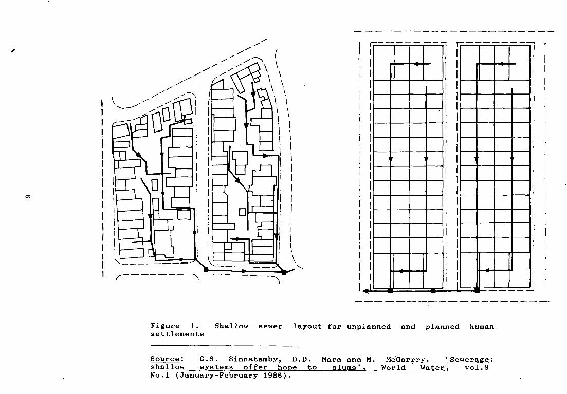
excreta, toilet flushwater, and sullage — in their fresh state foroff—site treatment and disposal. They consist of a network of small—diameter pipes laid at flat gradients in locations away from heavyimposed loads, such as vehicular loads, usually in the backyards andnarrow back alleys of both planned and unplanned settlements. Thisallows short overall lengths of pipework to bé laid in shallowtrenches (hence the name) witki small inspection chambers providedalong their lengths to facilitate access for maintenance. Most highdensity low—income housing areas have few motor—accessible roadswithin them and, hence, a majority of the sewers may be laid atshallow depths throughout most of their length. Typical layouts ofshallow sewer systems are presented in figure 1.
Shallow sewers are designed to be flushed frequently:essentially, all houieholds within a block are connected to the sewerthat passes through it. This is required not only to ensure trouble-f ree operation but, more important, to interrupt intra—communitycontamination. Several houses are connected to the same sewer which,when it emerges from the block, has several options: (a) to beconnected to a conventional street sewer; (b) to be discharged into acommunal septic tank and, thence, by a small—bore sewer to waste—stabilization ponds or other treatment process; or (c) to bedischarged straight into ponds. The choice is site-specific. Theshallow depths of the emerging sewers can often be maintained bylocating them in streets in places not subject to vehicular loadings,such as along footpaths immediately adjacent to property boundaries.Where it is unavoidable to cross streets subject to such loadings,suitably designed concrete collars are provided around the pipe toserve as protection.
B. Mode of operation
Shallow sewers do not rely on large quantities of flushwater fortrouble-free operation; instead, they rely on the high frequency withwhich wastewaters pass through the system. Densely populated areasoffer ample opportunities for such operation. At the head of thesewer network, wastewater solids are flushed along by successive wavesof wastewater, and, 1f any solids settle out in the sewer invert,wastewater builds up behind the deposit until the pressure is greatenough to set it moving again. Such back pressures are easilyestablished when the diameter of the pipe is small, since leakagespast the deposited solids are minimized and an effective backpressure can be built up. Solids progress along the top end of thesewer line in a sequence of deposition — transport — deposition —
transport, and this continues until the sewer has drained asufficiently large area for the flow to cease being intermittent.Shallow sewers are also laid out in such a manner that they arelocated adjacent to the wastewater generating points withinhouseholds. Hence, peak discharges created during flushing assistsolid tranport even when water consumption and, hence, wastewatergeneration are limited.
5
—
1”
Figure 1.settlements
Shallow sewer layout for unplanned and planned human
Source: G.S. Sinnatamby, D.D. Mara and M. McGarrry.shallow systems offer hope to slums”, World Water,No.1 (January-February 1986).
“Sewerage:vol .9
(

C. System advantages
Collecting all wastewaters from a settlement in the mannerdescribed above has seven principal advantages:
(a) Reduced water reciuirement. Since the sewers are designed forfrequent flushing, in a manner that all wastewater generated byupstream households assists solid transport down—stream, largequantities of water are not needed for solid transport. Thus, unlikeconventional sewers, shallow sewers can be employed without fear ofblockage in areas where domestic water consumption is low and wherewater-saving plumbing fixtures and appliances are widely used. Theyhave been successfully applied in areas where domestic waterconsumption does not exceed an average of 27 lcd. £/
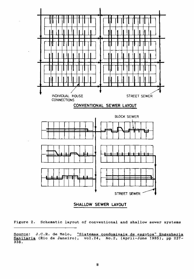
(b) Reduced length of pipework. Since short house connections arerequired and collector sewers are only necessary along some streets, aconsiderable reduction in the overall length of pipe network isachieved. This reduction may reach as much as 50 per cent in anefficient layout. Figure 2 illustrates the reduced length of pipeworkin shallow sewers when compared with conventional sewers.
(c) Reduced excavation costs. Since shallow depths are adoptedfor the bulk of the pipe network and sfnce the overall length of thenetwork is reduced, excavation costs are minimized. The reduced depthto which shallow sewers are laid also permits their implementation inhigh—density, unplanned areas where deep excavations could poseproblems, especially in settlements containing precarious housingstructures.
(ci) Reduced material costs. Small-diameter pipes are used in theshallow sewer system in order to promote good solid tranport. Inaddition, expensive, deep manholes, used to provide access for themaintenance of conventional sewers, can be replaced with much lesscostly shallow inspection chambers. This also obviates the need formechanical cleaning equipment which is not readily available indeveloping countries.
(e) Reduced maintenance reguirements. The increased frequency ofsewer flushing, ensured through connecting large numbers of houses toa single sewer at the initial stage of commissioning the system,reduces the possibilities of blockages during the early life of thesystem. The reduced length of pipework and the shallow depths alsofacilitate maintenance and offer potential for community participationin maintaining the lengths of pipework passing through individualpremises.
(f) High user connections. Because of the layout and mode ofoperation of shallow sewer systems, both the common house connections(sewers laid within the block) and street sewers are constructedconcurrently. Hence, most, if not all, househoids are servedimmediately upon completion of construction: for example, in asquatter settlement in north-east Brazil, a connection rate of 97 percent was obtained during the first year of construction. Such highrates of connectiori ensure that maximum benefits from the sanitationintervention are guaranteed from the outset. lJrban communityaspirations to have waterborne sanitation act to motivate communityparticipation and acceptance.
7
—
BLOCK SEWER
+ ‘ E~iIIE E E E E
— —
—
STREET SEWER
SHALLOW SEWER LAVOUT
Figure 2. Schematic layout of conventional and shallow sewer systems
Source: J.C.R. de Melo, “Sistemas condominais de esgotos” EngenhariaSanitaria (Rio de Janeiro), vol.24, No.2, (April-June 1985), pp 237-338.
INDIVIDUAL HOUSE STREET SEWER
CON NECTIONS
CONVENTIONAL SEWER LAYOUT
8

(g) Potential for reduced treatment reguirement. Where communalseptic tanks are located at the points where the sewers emerge fromblocks of houses and discharge their effluents to off-site treatmentvia small bore pipes, then screening, grit removal and primarysedimentation or treatment in anaerobic ponds are not needed at thetreatment works, because these processes are performed in the septictank. Clearly, the decision to incorporate communal septic tanks inthe system needs careful evaluation, to assèss cost trade—offs andlocal capacity to maintain the tanks.
Thus, relaxations in technical standards, brought about bydiligent. location of sewers and careful incorporation of recentresearch findings in the design and operation of sewers, have resultedin the development of an acceptable means of providing sanitationfacilities at a level of service comparable with conventional seweragebut at a much lower cost. Because of their low costs of constructionand maintenance and their ability to function with little water,shallow sewers can be used where conventional sewerage would beinappropriate. Shailow sewers, therefore, offer an opportunity ofimproving sanitation in a majority of low—income urban settlements indeveloping countries. The principal disadvantages of the shallowsewer system are that it requires extensive promotion of communityawareness, together with house-to—house and physical surveys, at theplanning stage, and good quality control during construction.However, the efforts devoted to promoting the system amongst low—income communities will enable them to identify themselves with thesystem, which, in turn, will result in its improved operation andmaintenance in the long run.
D. Component parts
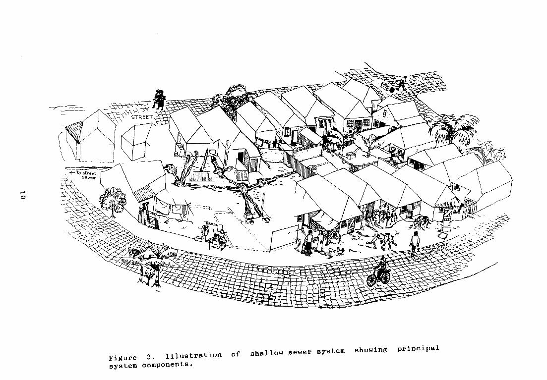
Shallow sewer systems consist of the following components: (a)house connections; (b) inspection chambers; (c) common block sewerlines; (d) street collector sewers; (e) pumping stations (onoccasions); and (f) a sewage treatment plant (see figure 3). Pumpingstations are only necessary if the collected sewage cannot be treatedand disposed of within the same drainage basin. They may, also, berequired in the sewer system itself in extremely flat areas, but thisis very rare.
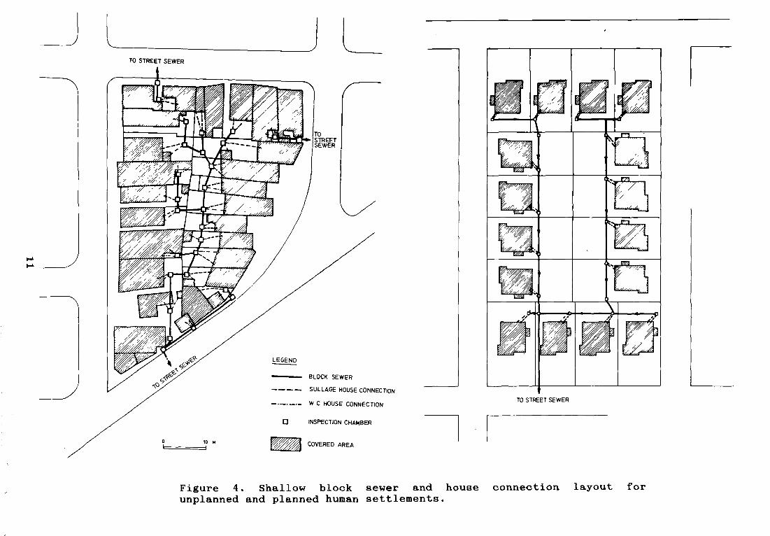
(a) House connection. All household wastewaters are connected tothe common block sewer line at an inspection chamber along its length(see figure 4). Low—volume pour-flush or cistern-flush watersealtoilets (either pedestal seat or squat pan units) are connected to theinspection chamber via a 75 mm diameter, PVC or asbestos cement pipe.A vertical ventilation column of the same diameter is providedsomewhere along the length of the house ,connection. (Conventionalflush toilets may also be connected, but because the system does notrequire large quantities of water for its operation, their use is notprudent. A variety of low-volume waterseal pedestal seat and squatpans are available, and these are more than adequate.) All sullagegenerated on the premises is also connected to the inspection chamberby a suitable pipe, usually a 50 mm diameter PVC pipe. Where waterconsumption is large (greater than 75 lcd), the sullage may beconnected directly to the inspection chamber. However, whereconsumption is low (25-30 lcd), it is advisable to pass the sullagethrough a grit/grease trap which acts as a sullage collector and alsoserves as a preventive maintenance device. Low levels of waterconsumption are usually associated with settlements served with acommunal—standpipe level of water supply.
9
t—
0
Figure 3. Illustration of shallow sewer system showing principalsystem components.
1V-’
BLaCK SEWER
SULLAGE HOUSE CONNECrION
W C HOUSE CONNECTION
COVERED AREA
Figure 4. Shallow block sewer and house connection layout forunplanned and planned human settlements.
LTO STREET SEWER
7
ISEWER
LEGEND
0 10 M1 i
0 INSPECTION CHAMBER
TO ST~ETSEWER

(b) Inspection chamber. Inspection chambers are provided atfrequent intervals along the length of the common block sewer line.They serve both to provide access to the sewer line for the houseconnections and to facilitate sewer maintenance. Usually oneinspection chamber is provided for each house, although, depending onthe sewer layout, two or more houses may share a single inspectionchamber. The dimensions of the chambers vary with depth. A tightlyfitting reinforced concrete cover is provided to the chamber.
(c) Common block sewer line. The block sewers are small—diameter (minimum of 100 mm) day or concrete pipes which are trenchedinto the ground at a depth sufficient to collect wastewatersdischarged from the house connections by gravity and laid at a uniformgradient between adjacent inspection chambers along their length.Usually, a minimum depth to pipe invert of 0.4 m is provided to avoidaccidental damage, although this may be reduced in specialcircumstances. The block sewers, while following a straight alignmentbetween inspection chambers, rarely follow an overall linear alignmentin unplanned settlements and are usually contoured around existingbuildings. The objective in such a layout is to ensure that the blocksewers are laid adjacent to all wastewater-generating points withinthe block: some straightening out of the sewer line will, however, bedesirable. The sewer line will inevitably be required to pass underproperty boundary walls and, possibly, under future building extensionareas: however, this does not usually pose any serious problem. Stoneor brick arching of the wall or foundation will assist in avoiding thetransmission of dead loads directly on to the pipe. The inspectionchamber must, however, always be located in an open area.
(d) Street collector sewers. Street collector sewers are usuallyprovided to a minimum diameter of 150 mm, although it is possible,where hydraulic capacities permit, to adopt 100 mm diameter pipes.They are ,laid at a depth compatible with their location. Whereverpossible, they are laid under sidewalks away from vehicular traffic,at a depth which ensures the continuation or the flow within them andwhich is also adequate to receive the discharge from the block sewers.Where the depth to pipe invert exceeds 0.8 m, the sewers may belocated, without protection, in streets subject to vehicular loadings.Where pipes are laid at depths less than 0.8 m, a concrete surroundis provided at selected locations, for example where they pass undervehicular traffic, in order to protect the pipe. Inspection chambersare provided along the street collector sewers at intervals notexceeding 40 m, although, where meôhanical sewer cleaning devices areavailable, this distance may be increased. Where communal septictanks are provided at the point of emergence of the block sewers, thestreet sewers should be designed in accordance with the principles ofsmall—bore sewers .5/
(e) Pumping stations. Pumping stations may be necessary wherethe sewers become very deep or when it is required to transport thecollected sewage to a different drainage basin for treatment anddisposal. The use of pumping stations should, however, be eliminated,as far as possible, through careful sewer depth minimization and bytreatment of all wastewaters within the same drainage basin.
(f) Treatment plants. In certain circumstances, it may bepossible to discharge the wastewater into an existing conventionalsewer system and, thus, be able to treat it at the works receiving theunsettled sewage. Where this is not possible, waste stabilizationponds are generally the wastewater treatment option of choice in
12
developing countries. 1f the number of houses served is small,treatment may also be provided by means of a communal septic tank andeffluent infiltration trench.
Detailed criteria for the hydraulic design of shallow sewers andtheir appurtenances are discussed in chapter II. A design example isincluded in annex 1.
E.Applicability in developing countries
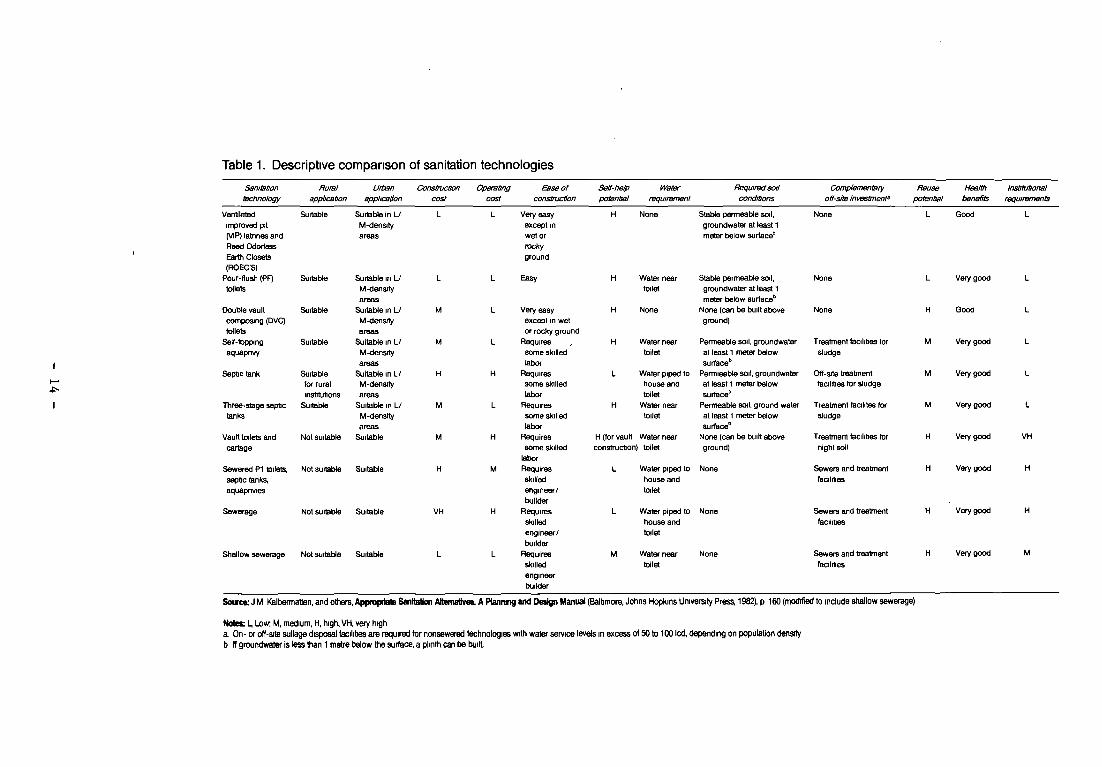
A recent study undertaken by the World Bank 3/ identified avariety of on—site and ofî—site excreta and sullage disposal systems(a descriptive comparison of a variety of relevant sanitationtechnologies is presented in table 1). On-site excreta and sullagedisposal systems were found to be much less expensive in developingcountries’ than off—site systems. However, shallow sewerage, which wasdeveloped after this study, is probably the only off-site systemwhich, in certain conditions, is cheaper than on-site systems. Thereare also situations where on—site systems are technically unfeasible,and in such circumstances some form of off—site disposal is required.Shallow sewers are usually the most economical of all off-sitedisposal technologies and are therefore an obvious choice forconsideration. Fortunately, it is precisely the same conditions whichrender on—site systems unfeasible or too expensive that make theshallow sewer system attractive in both technical and economic terms.These conditions include:
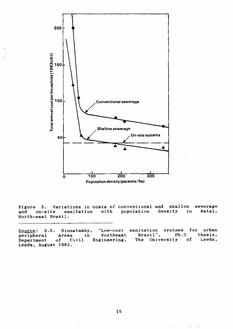
(a) High population densities. All on-site waste disposaloptions require adequate space within the lot for their installation.Such space is usually available in rural and low-density to medium-density urban areas. However, as the density of settlement increases,such space is not readily available, and, even when it is available,on-site systems are likely to meet with community oppositionespecially because they need desludging at some stage during theiroperation. All forms of pipe networks demonstrate marked reductionsin unit household costs as the density of settlement increases,because the same length of pipework serves an increased number ofhouses. On—site systems, however, maintain a constant unit householdcost irrespective of the density of settlement. At a given density ofsettlement, piped networks become more economical than on-sitesystems. Unfortunately, in the case of conventional sewerage thistransition only takes place at extremely high population densities.Shallow sewers, being much cheaper than conventional sewers, becomecost-effective at much lower densities. The population density atwhich this transition takes place varies with the physical conditionsof the settlement (such as soil permeability, topography etc.), but inNatal, Brazil, this transition point occurred at a density of 160persons per hectare (see figure 5). In areas with shallow rock,shallow sewers have even proved more cost—effective than on—sitesystems at population densities as low as 110 persons per hectare. ~j
(b) Adverse ground conditions. All on—site excreta and sullagedisposal systems rely on the ability of the soil to absorb allwastewaters generated on the premises. They also require some form ofexcavation for excreta storage. linder adverse ground conditions, suchas shallow rock, high groundwater table and low soil permeability, on—site systems may become unfeasible. The shallow sewer system is oneof the off—site options which may be adopted in such circumstances.
(c) High water consumption. Most low—cost, on—site wastedisposal systems, such as pit latrines and pour—flush latrines, only
13
1-’
Table 1. Descriptive compansonof sanitationtechnologies
tiotet L bw~f.1, medium, H, high, VH, very higha. 0fl- or otf-sde sullagedisposal ~ihtteswe required for nonsewered technologies wall water service laoS in excess of 50 to 100 lcd, depertding on population dens’fyb ffgmunwSrlclessthan1metebalowÛieaurtac~apiinthcanbebuiIt
Serswba’mtactrnotogy
Rumiappilcaûon
Lijban~ep/icatlon
C~mnobo,ctoncoat
4~,eraÖngcoat
Ene ofconstnicffon
Seff-fla’ppotenlia/
Wrntor Requir~so./requiremenl cond,aons
Con~Smenbiyoff-s/te /nweijnent~
Heusepolwtks/
Heaf~lbenefiet
/nsüaiaona/raquuwr.ents
Ventilated Suitetee Surtable in L/ L L Very easy H Norie Slstae penneeble set, None L Good Limproved p1 M-densrty escept in groundwater at leest 1(tiP) letnneaend erees wat or meter below surtaca~Reed Ddorteas rockyEarlh Closets ground
(ROEC’S)Pour-kust, (PF) Suiteble Suitable in L/ L L Easy H Water near Stable permeable soil, None L Veiy good L
tellers M-dens.tyareas
toilet groundwater al leasl 1meter below aurta&
Douteevault Suitable SurtableinL/ M L Veryeaay H None None(canbebuiltabove None H Goed Lcornpos.ng )DVC) M-dertsrty eecept in wet ground)tellers wees orrockyground
Selt-toppirig Suiteble Suiteble in Lf M L Requirea H Water neer Perrneeble sod, groundwater Treatmnent taolittee lor M Very goed L
aquapnvy M-densrty
weessome alelled
labortoilet al leest 1 meter betow
surtecebakidge
Septrc tank Suitable Suitatee in Lf H H Requires L Water pipedto Permieeble soil, groundwater Dit-arIa treaterent M Very goed Ltot rural M-denarty seine slelied houseend eI leest 1 meter betow tacilaee lor sludgeinatrtutioris areas labor toilet surtace~
Three-stage septic Surteble Suitable in LJ M L Requiree H Water neer Permeatse aod, groundwater Treate,ent tecilitea Ier M Very goed Ltenka M-derislty
weesseine slelledtebor
toilet al leest 1 meter belowsurtacei)
akidge
Vsult toilete and Not suiteble Surteble M H Requires H )tor sauS Water neer Norie )cen be buik ebeve Treatrneet tecilitree ter H Very goed VHcartege seine akilled conalruclron) toilet ground) night aoil
boerSewered Pl tede~ Not aurtabte Surtable H M Requires L Water piped to None Sewera and trealmeet H Very goed H
aepac tenk~ elrilled houaeand teciteeeaquspnviea
Sewerage Nol sulteble Suitebte VN H
engineerlbunder
Requimaslelledengineerlbuitder
L
toilet
Water piped to Netteheuse andtoilet
Sewers and freelmenttacilstes
H Very goed H
Shailow sewemage Not surteble Sudable L L Requlreealrilled
M Water neer Nonetoilet
Sewers and freateianttacilrbee
H Very goed M
engineerbullder
Sooict J M Kalbermattan, and other~AppeopflateSailIaxn Aitemativea. A Ptannaag and Dealgn ManuS )Bsiltmore,Johns HopkinsUniversdy Prea 1982), p 160 )modtfied to indude stisilow sewerage)
200
(1)
ci)DmT0)
~00
.c0(S,
0.c1-
0100
0(.3
0
cc0St.01-
Figure 5. Variations in costs of conventional and shallow sewerageand on-site sanitation with population density in Natal,North-east Brazil.
Source: G.S. Sinnatamby,peripheral areas inDepartment of CivilLeeds, August 1983.
“Low—costNortheast
Engineering,
sanitation systems for urbanBrazil”, Ph.D thesis,
The University of Leeds,
100 200Population density (persons/ha)
15

handle the disposal of excreta. Sullage is usually left to infiltrateinto the ground at the surface or via some form of on—site sullagesoakaway. As water consumption increases, the need for such soakawaysincreases. In areas of adverse soil conditions and high densities ofpopulation, the space for soakaways may not be readily available.Further, because low—income communities do not see the need forinvesting in soakaways for the disposal of sullage, it is not uncommonto see large quantities of sullage flowing in the streets. Suchuncontrolled disposal of sullage can give rise to diseases such asfilariasis, as well as erode the usually unsurfaced alleyways found inthese settlements. Shallow sewers, because they dispose of bothexcreta and sullage, can be adopted in settlemênts where averagelevels of water consumption are high. A minimum average water con—sumption of at least 25 lcd is required, however, to be available forshallow sewers to operate without blockages.
(d) Varied. socio—cultural settings. Shallow sewer systems maybe applied under most socio-cultural settings. It is especiallysuited to cultures where anal cleaning by water or soft materials isused. No experience is available on which to assess their suitabilityin areas where bulky anal cleaning inaterials are used.
When on—site disposal technologies prove unfeasible or whendensity of settlement suggests that off-site systems may prove cost—effective, the full range of off-site disposal technologies has to beevaluated in technical, financial and economic terms. The availableoff-site disposal technologies are the following:
(a) Vault toilets and cartage systems. These require a highdegree of organizational capability within the institution (usually amunicipality) responsible for operating the system: the vault-emptyingequipment (commonly a vacuum tanker) has to arrive at each vault veryclose to the chosen emptying frequency (two to four weeks), otherwisethe system fails, and the emptying equipment must be properlymaintained. In many developing countries, such a level ofinstitutional competence is lacking, and very often the system cannotbe considered feasible for this reason. Narrow access roads to mostlow-income settlements in developing countries would also suggest thatthe system may not always be appropriate.
(b) Conventional sewerage systems. These are so expensive thatthey are economically inappropriate in low—income communities. Forexample, studies undertaken by the World Bank 3/ showed thatinvestment costs for conventional sewerage in eight capital cities indeveloping countries ranged from $600 to $4000 (at 1978 prices) perhousehold, with corresponding annual costs 7/ between $150 and $650per household. Such costs are clearly unaffordable when it isremembered that total annual household incomes are frequently lessthan $500 and are often below $200. Further, the unfeasibility ofconstructing deep sewers in high—density areas with precarious housingstock also precludes the use of conventional sewerage in low—incomesettlements.
(c) Small—bore sewers. These offer a feasible means of upgradingon—site systems, such as pour-flush toilet and septic tank systems,when improvements in the water-supply distribution system or increasedhousing densities have occurred. In new schemes, however, smali—boresewerage offers little advantage over conventional sewerage in termsof overall cost. Small—bore sewerage, as with the vault system, alsonecessitates frequent desludging. The equipment and organizational
16

capability for this task may not be readily available in developingcountries, and access for purposes of desludging individual householdseptic tanks may not be adequate in mogt low-income, high-density set-tlements. In these circumstances, small-bore sewerage not only willprove to be only slightly cheaper than conventional sewerage but, moreoften than not, may prove technically inappropriate.
(d) Shallow sewer systems. These become increasingly economicalas the density of settlement increases. In high density slums andsquatter settlements, they are often cheaper than on-site systems:typical investment costs are in the range of $125 to $325, withcorresponding annual economic costs 7/ between $15 and $35 perhousehold. The very high rates of user connection, usually achievedthrough community involvement at the planning and implementationstages, ensure that a comprehensive sanitation solution is providedfor the whole community and that maximum health impact is achievedimmediately upon completion of the scheme. Besides being considerablycheaper than conventional sewerage, shallow sewers do not requireexcessive quantities of flush water for trouble-free operation.
17

II. SHALLOWSEWERDESIGN CRITERIA AND SPECIFICATIONS
A. Design considerations
A shallow sewer system is a separate sewer system which utilizesgravity for conveying raw sewage from all households to an outletdownstream. It must be set deep enough to receive flows from eachuser but must be located so that this depth is kept to a minimum. Itmust have sufficient size and gradient to carry these flows. Inaddition, maintenance operations, public safety and convenience mustbe evaluated in the light of water availability and the potential foruser participation.
Suitable preventive maintenance devices, such as grit/greasetraps, must be provided where water consumption is low and where sandand other inert materials are used, instead of detergents, forcleaning utensils. Shallow depths must be maintained not only forecdnomy in construction but also for facilitation of user maintenance.Frequent sewer flushing, achieved through the connection to a singlesewer line of a number of houses, must be ensured for good operation.Pipes with sufficient structural strength must be used, and suitablebedding materials must be selected to withstand backfilling, andimpact and live loads where these are likely to occur. The type andnumber of appurtenances used must facilitate cleaning of the sewerswith the kinds of cleaning equipment likely to be used. Publicconvenience and safety during construction are additional importantfactors.
B. House connections
All household wastewaters are drained to an inspection chamberlocated along the length of a common block sewer line, usually throughtwo or more pipe connections. One of these is for the water closetconnection and, depending on the distribution and number of sullagegenerating areas within each house, one or more sullage connectionsare also provided. Where a grit/grease trap is provided, it is usualto connect all the sullage to it and provide a single connecting pipeto the inspection chamber.
1. Water closet house connection
This connection is the short length of pipe that drains the watercloset to the inspection chamber. A vertical ventilation column isusually provided somewhere along the length of the connection, oftenadjacent to the exterior wall of the house. The followingspecifications are recommended for the water closet house connection:
Pipe materials for house connection
and ventilatjon column: PVC or asbestos cement
Pipe diameter for house connection
and ventilation column: Minimum, 75 mm
- Pipe gradient of house connection: Minimum, 1 in 50
Manually flushed squat pans, using 3 litres of water per flush,have been shown to be capable of transporting simul-ated wastematerials an average distance of over 5 metres along 75 mm diameter
18

pipes laid at a gradient of 1 in 100. 8/ 9/ Since the layouts ofshallow sewers are such that the common block sewer line is adjacentto the toilets, the water closet connections are usually short inlength and rarely exceed 5 metres. Even so, a minimum gradient of 1in 50 is recommended to take account of variations in site and sewerlayout. Clearly, the shallowest gradienta may be adopted wherepedestal seats using large flush volumes are adopted. In any event, agradient not flatter than 1 in 100 is recommended.
2. Sullage house connection
Where water consumption is low (25-30 lcd) and where sand, brick-bats and other abrasive materials are customarily used for cleansingutensils, all sullage house connections must be preceded by some formof grit/grease trap, especially for kitchen wastewaters. Even wherewater consumption is high and detergents are used for cleaningutensils, it is advisable to provide this preventive maintenancedevice. When the overflow pipe from these devices, i.e., the sullagehouse connection, is free from gross accumulation of solids, it may belaid at a very flat gradient. Direct connections to the common blocksewer inspection chamber may also be made from laundry and bathingareas, including also kitchen wastewaters, in areas where the averagewater consumption is over 75 lcd. The following specifications arerecommended for sullage house connections:
Pipe material: PVC
Pipe diameter Minimum, 38 mm but usually 50 mm
Pipe gradient Minimum, 1 in 200
C. Common block and street collector sewer
Within a block, all water closet and sullage house connectionpipes are connected to a single pipe known as the common block sewer.Where the natural drainage path within the block is unidirectional,only a single block sewer is necessary. Where this is not the case,in order to minimize excavation and follow the natural fall of theland, it may prove necessary to adopt more than one common blocksewer.
The common block sewers are designed to be flushed frequently,and therefore as many houses as possible should be connected to them.They should be located adjacent to the toilets they serve and are,hence, usually located at the backs of houses. In certain housinglayouts where the toilets are located at the front, block sewers arealso provided at the fronts. When the block sewer emerges from theblock, it is connected to a street collector sewer. Since blocksewers and street collector sewers operate in a similar manner,criteria for their design are discussed together below.
Traditionally, the design of sewers has been based on theconcept of ensuring that peak daily flows carry away any solidedeposited during periods of low flow. These self-cleansing velocitiesoccur at least once a day in the large downstream sewers but notusually in the small—diameter house connections and street collectorsewers in the upper reaches of the network where the flow isintermittent. Recently, however, the concept of self—cleansingveloci.ties in sewers as a basis for their design has been questionedby many researchers. It has been found that, although solids aredeposited in pipes, they become re—suspended and transported on
19

subsequent flushing, as the pressure force caused by the difference indepth of water across the solide increases. 10/ 11/ Solide aretherefore shifted along the pipes by the flushing action of sequentialwaves of wastewater, and, as solide deposit in the pipe invert,wastewater backe up until the pressure is sufficient to move thesolide forward. Based on these findings, it has been suggested thatthere is no reason to attempt to design a totally deposit free houseconnection or sewer. 10/
A comprehensive study of the causes of blockage in houseconnections, conducted in the United Kingdom, 12/ concluded that mostsewers experienced intermittent stoppages during normal operation andthat these were removed by wave action rather than by the maintenanceof a minimum scour velocity. Blockages were observed to be removedefficiently as the depth of flow increased and were primarily theresult of poor workmanship and infrequent use of the system, ratherthan of limitations in pipe diameter or gradient. It would appear,therefore, that recent studies undertaken on the operation of sewersdo not suppôrt the current design practice of restricting the use offlat gradients by working to a minimum mean velocity.
Unable to model the true mode of operation of sewers, especiallyat the upper reaches of a network, engineers have resorted to rules ofthumb which have become increasingly conservative over the years, thusadding unneceesarily to the cost of eewerage. Current knowledge etilloffers no alternative to using the self-cleansing velocity designconcept. It is on this principle that procedures have been developedfor the design of shallow sewers, although recent research findingshave enabled substantial changes to be made in design standards andcriteria to promote cost reductions. These are discussed below.
1. Minimum and maximum velocities of flow
Minimum peak daily velocities in pipee have been said to liebetween 0.76 m/sec fl/ and 1.0 m/sec. 14/ However, laboratorystudies haye shown that solide do not decelerate until they reach athreshold velocity below which no further motion is possible; thisvelocity, depending on solid shape, pipe size and slope, relative piperoughnese etc., was found to be between 0.2 and 0.4m/sec. 9/ 15/Inert material will, however, be deposited at velocities below0.3m/sec. Accepting these findings and assuming that sewers do notoperate on the principle of self-cleansing velocities and that, whensolide are deposited they become re-suspended and transported bysubsequent flushes, a minimum flow velocity of 0.5m/sec is consideredadequate. In Brazil, sewers have been designed for this value ofself-cleansing velocity for over two decades. 16/ Maximum velocitiesof flow have, in the past, been specified, in order to reduce thepossibility of pipe erosion. Such effects were said to occur at flowvelocities in excess of 4.Om/sec, but studies have shown that erosioneffecte observed at velocities greater than this threshold value areonly minimal, 17/ and hence no upper limit of flow velocity isrecommended. Thus, the minimum and maximum sewage design velocitiescan be stated as follows.
Minimum (self-cleansing) velocity: 0.5 m/sec
Maximum velocity: No limit required
20t
2. Minimum and maximum depth of flow
Minimum and maximum proportional depthe of flow, at peak flow,are usually epecified for pipes conveying sewage, in order to ensurethat a sufficient sewage flow for solid transport and an adequatesurplus capacity are provided in the pipe. A minimum proportionaldepth of 0.2 is generally considered neceeeary for eolid transport,and a maximum proportional depth of 0.8 ie usually recommended inorder that approximately 8 per cent surplus capacity is available toprovide a smal~l margin of safety againet underestimation of the sewageflow. Since it is now known that solide are deposited in sewers andtransported on subsequent fluehes, epecifying a minimum depth of flowwould appear to be unnecessary. However, in the absence of exactdesign methode, the maintenance of a minimum and a maximumproportional depth ie recommended as followe:
Minimum depth of flow in pipe: 0.2 timee pipe diameter.
Maximum depth of flow in pipe: 0.8 timee pipe diameter.
3. Minimum eewer diameter
A minimum eewer diameter of lOOmm ie usually recommended. j~JÂffiJAlthough 75mm diameter pipee have been succeesfully utilized inScandinavia 19/ it is unlikely, in moet developing countriee, thatpipee made of suitable material are obtainable at a diameter of 75 mmand, even if available, that they are cheaper than a 100 mmdiameterpipe made of commonly available materials, such as day and concrete.Further, it is also difficult to ensure good workmanship in pipe-jointing at reduced pipe diameters. Hence, a minimum pipe diameter of100 mm is recommended. Since small—diameter pipee have been shown tohave better eolid—transport properties than large-diameter pipes,becauee of their ability to build greater depthe of water behindeolids, 10/ 11/ there is no juetification for using pipe diameters inexcese of 100 mm, except when required by the magnitude of the flow.In fact, it ie definitley not advieable to increaee the pipe diameterunder the reduced falle propoeed for ehallow eewers, eince thisdecreases the depth of flow, and solide will thue tend to be depoeitedfrequently in the pipeline. The following recommendation ie,therefore, made regarding the minimum sewer diameter:
Minimum sewer diameter: 100 mm
4. Minimum sewer gradient
A wide range of minimum gradiente has been recommended in thepast. The study of the cauees of eewer blockages in the UnitedKingdom 12/ found that sewer gradiente, as with pipe diametere, werenot determining factors in caueing eewer blockages. House connectionslaid at gradients as flat as 1 in 1200 were found to operatesatiefactorily for many years. In fact, the investigation diecoveredmoet blockages on the commonly recommended gradiente of between 1 in30 and 1 in 70. British practice 18/- recommends that a 100 mmdiameter pipe be laid at a gradient not flatter than 1 in 70, providedit eerves the equivalent of at leaet one water closet, and 1 in 80,when serving up to five housee. As pipe diametere increaee, it ieoften common to see recommendatione to adopt ehallower sewergradiente: a minimum gradient of 1 in 150 ie often recommended for150 mmdiameter sewer pipes. 20/. Minimum pipe gradiente are, however,independent of pipe diametere. Ueing Manning’s equation, it can beehown that the gradient required for a pipe ie given by the following
21

equation:—2/3 8/3 - 2 —2/3 4/3
1 z Q V 1.59n (e-Sine) 9
where 1 : gradient, m/m
Q = flow rate, 1/eec
V = velocity of flow, m/sec
8 = angle eubtended at the centre of the pipe
by the wetted perimeter, radiane
- n = roughnese coefficient
Taking the limiting conditions (in the upper reaches of a sewernetwork) of a minimum depth of flow of 0.2 times the diameter(0:1.85459) and a velocity of flow of 0.5 m/eec, and aseumingManning’s roughnees coefficient n 0.013, the minimum pipe gradientie given by:
—2/3= 0.O1Q
It follows that, for a given diecharge the minimum permiesiblegradient is independent of the pipe diameter.
The above equation may be ueed to obtain minimum gradiente for arange of flows. Brazilian practice recommends that the flow from asingle cistern—flush unit of 2.2 1/eec be used to represent theminimum discharge at the head of any sewer system.jj/ Clearly, suchdiecharges are rapidly attenuated in the house connection as thesolide move away from the water closet, and they are never obtained inpractice in the sewers, but no probleme have resulted fromfollowing this aeeumption. It is interesting to note that over 200households with an average of five pereons per household and anaverage flow of 100 lcd would be required to generate a flowequivalent to 2.2 1/sec. The minimum gradient corresponding to adischarge of 2.2 1/eec is 1 in 167 (0.6 per cent), and this attains amaximum self—cleansing velocity of 0.5 m/s. The recent euccess withminimum gradients of 1 in 167 in shallow eewer systems in Pakistan, insettlements where water consumption averaged only 27 lcd and wheremanually flushed squat pans were utilized for excreta deposition, 21/22/ 23/ coupled with the fact that sewers do experience intermittentformations -of blockages, would suggest that very flat gradients maybe safely adopted in areas of medium and high water consumption.However, in the absence of additional field data, a minimum sewergradient of 1 in 167 is recommended.
Minimum sewer gradient = 1 in 167
5. Maximum number of houses to beconnected to a single sewer line
British practice recommends that a maximum number of only 20 and150 houses be connected to a single 100 mm and 150 mm diameter pipe,reepectively. 18/ Yet, the same code suggeste that, for waterconsumption levele lees than 140 lcd, peak flows of 0.01 1/eec perperson should be considered. On this basis, as many as 74 houses with
22
an average of five persons per house may be connected to a 100 mmdiameter pipe laid at a gradient of 1 in 167. Although this number ofhouses and the corresponding gradients are both well in excess of thecode recommendations, they are, in fact, almost exactly the same asrecommended by the Institute of Plumbing, United Kingdom. 24/ On asimilar basis, 219 houses may be connected to a 150 mm diameter pipelaid at the same gradient. Placing an arbitrary limit on the numberof houses which may be connected to a pipe of a given diameter, eventhough it possesses sufficient hydraulic capacity to drain many morehouses, is clearly irrational, especially in the light of recentfindings that sewer blockages are often the result of infrequentusage. 12/
Conventional British practice also recommends that each house beseparately connected to the street lateral, and this sometimesnecessitates very long house connections. Recently, up to four houseshave been allowed to use a common connection, but private developershave emphasized that savings of up to a third could be achieved byconnecting 20 houses by means of a common connection. 25/ In Brazil,up to 60 houses have been connected to a 100 mm diameter pipe laid ata gradient of 1 in 167, although hydraulically over 200 houses may be50 connected. 26/ Given the possible economic and operationaladvantages of connecting a large number of houses to a single sewerline, there is little justification for limiting the number of housesthat may be connected to a sewer, provided sufficient pipe capacity isavailable. Since water consumption and wastewater generationpatterns are often different from country to country, the maximumnumber of houses to be connected to a sewer should be computed orj thebasis of the peak flow and the maximum flow capacity corresponding tothe minimum gradient (see hydraulic design below). The flow-carryingcapacities of downstream street sewers should be established todetermine the number of houses that may be connected to these pipes.
6. Minimum depth of sewer
One of the moet important features of shallow sewers, that has amarked influence both in reducing the overall cost of sewerage and infacilitating maintenance, is that the sewers are laid at a shallowdepth. Usually, the minimum depth of block sewers is determined bythe depth to invert of water closet and sullage house connections.Because the length of these connections is usually short, it ispossible to lay pipes at a minimum depth to soffit of pipe of only0.2m. However, in order that accidental damage to pipework may beavoided, it is prudent to adopt a minimum soffit cover of 0.3 m. Thisimplies that a 100 mm diameter block sewer will be laid at a minimumtrench depth only marginally greater than 0.4 m. While such depthsare acceptable in areas not subject to vehicular loadings,continuation of the use of such depths, once the block sewer emergesinto the street, necessitates careful location. Where it isinevitable that vehicular traffic pass over the line, pipes must belaid with a minimum cover to soffit of 0.8 m or, alternatively, thepipe must be protected with a concrete collar (see section D).
7. Peak sewage flow estimation
The peak flow at various stages of the pipe network may becalculated from the following equation:
Q = C.K1.K2.P.ci + Q1 + Q286400
23
where Q = peak sewage flow at a point along the sewer in 1/sec
C = fraction of consumed water which returns as sewage*
Xl = coefficient of flow variation above the average dailywater consumption on the day of maximum waterconsumption* *
K2 = co-efficient of flow variation above the average dailywater consumption during the hour of maximumconsumption* * *
P = total population along the stretch of sewer underconsideration;
q = average water consumption in lcd
Ql = groundwater infiltration in 1/sec +
Q2 = point discharges to the stretch of sewer underconsideration including upstream discharges in l/sec and
86400 = number of seconds per daS’.
(the percentage of water supplied to a house which doee notreturn as eewage) is water used for such purposes as wateringgardens and washing floors, cars and the like. However, suchlosses are likely to be minimal in low—income settlements.In the absence of more reliable field data, approximately 15to 20 per cent of the total volume of water supplied to thesesettlements may be assumed not to return to the sewers.Thus, a value between 0.80 and 0.85 is recommended for thecoefficient C.
** Xl (the ratio of the average daily flow on the day of maximumconsumption to the weekly average daily flow) is usually ofthe order of 1.2.
K2 (the ratio of the average daily flow during the hour ofmaximum consumption to the weekly average daily flow) isusually within the range 1.5 to 2.0 . 16/
+Q1 Where sewers are laid below the groundwater level someingress of groundwater into the pipe may be expected.Ideally, the addition of such water should be zero, but, inpractice, some imperfectly sealed pipe joints will result ininfiltration. 1f the prevention of groundwater ingresscannot be ensured, some allowance must be made forinfiltration. This allowance is often quoted either as avolume of infiltration water per hectare per day (a typicalconservative figure may be of the order of 20 m3/ha/day) oras a flow per kilometre length of sewer (a typical range ofrange of values may be 0.2 to 0.3 l/sec/km).
24
Although several equatione are available in the literature forrelating peak eewage flows to average sewage flows and contributingpopulations, 27/ moet of these were derived from experience inindustrialized countries. The above equation was, however, obtainedfrom Brazilian practice, and it has been succeesfully applied in thedesign of a number of shallow sewerage schemes. Unless detailedlocal information is available, its use for shallow sewer design isrecommended. In conventional sewer design, it is necessary toconsider the initial and final populations to be served and theiraverage rates of water consumption, because these are likely to changewith time. However, the sewer design method presented here obviatesthe need for considering the initial sewage flow and requires thatonly the final peak flows be considered in order to establish thenecessary pipe capacities. The fact that a minimum gradient isprovided in the sewer designs, based on a minimum flow associated withthe flushing of a water closet from a single household, ensures thatthe need to coneider initial populations and water consumptions iseliminated. The minimum gradient recommended above has beeneetablished through successful practical application in areas of lowwater consumption where manually—flushed squat pans were provided forexcreta deposition.
8. Hydraulic design
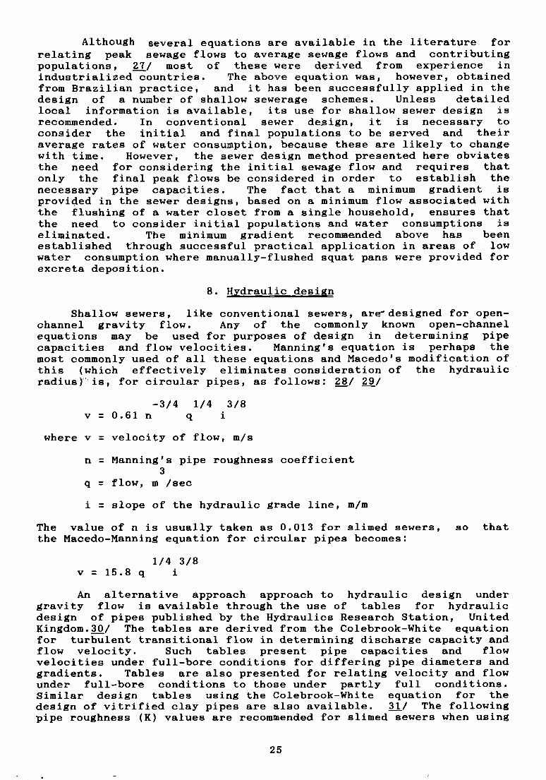
Shallow sewers, like conventional sewers, aredesigned for open—channel gravity flow. Any of the commonly known open-channelequations may be used for purposes of design in determining pipecapacities and flow velocities. Manning’s equation is perhaps themost commonly ueed of all these equations and Macedo’s modification ofthis (which effectively eliminates consideration of the hydraulicradius) is, for circular pipes, as follows: 28/ 29/
—3/4 1/4 3/8
v=0.61n q i
where v = velocity of flow, m/s
n = Manning’s pipe roughness coefficient3
q = flow, m /sec
i = slope of the hydraulic grade line, m/m
The value of n is usually taken as 0.013 for slimed sewers, so that
the Macedo-Manning equation for circular pipes becomes:
1/4 3/8
v=15.8q i
An alternative approach approach to hydraulic design undergravity flow is available through the use of tables for hydraulicdesign of pipes published by the Hydraulics Research Station, UnitedKingdom.30/ The tables are derived from the Colebrook-White equationfor turbulent transitional flow in determining discharge capacity andflow velocity. Such tables present pipe capacities and flowvelocities under full-bore conditions for differing pipe diametere andgradients. Tables are also presented for relating velocity and flowunder full—bore conditions to those under partly full conditions.Similar design tables using the Colebrook-White equation for thedesign of vitrified day pipes are also available. 31/ The followingpipe roughness (K) values are recommended for slimed sewere when using
25

either of the two Colebrook-White equations.
Concrete: 6.0 mm
Asbestos cement: 6.0 mm
Clayware: 1.5 mm
PVC: 1.5 mm
Having computed the flow of sewage along a pipe length, the sewerie designed to ensure that the following conditions are satisfied:
(a) Minimum self—cleansing velocities are attained. Ensuringthat minimum gradients are provided automatically ensures that minimumself-cleansing velocities are attained.
(b) Depths to which pipes are laid are minimized withinpermissible limits.
(c) Adequate pipe flow capacity is available to carry themaximum peak future design flow.
(d) The depth of flow at peak flow is within the recommendedlimits. Once again, ensuring that minimum gradient requirement issatisfied will automatically ensure that the minimum depth of flow isprovided. Since the maximum permissible depth of flow occurs at aflow equal to the full-bore flow (i.e, when d/D = 0.8, q/Q = 1) duringfull-bore condition, there is no need to verify that this condition issatisfied as long as condition (c) above is satisfied, i.e., providedthat the sewer does not become surcharged.
(e) Minimum sewer diameters are provided.
An example of shallow sewer design using the above criteriais presented in annex 1.
D. Apnurtenances
1. Pour-flush water-seal units
All forms of conventional pedestal toilet seats may be used inconjunction with the shallow sewer system. However, these useunnecessarily large quantities of water (9-19 litres ~er flush).
‘Because shallow sewers do not need large quantities of flush water,manually flushed squat pans and pedestal seats which use approximately3 litres of water per flush may also be utilized in conjunction withshallow sewers (see figure 6). Recently, low—volume cistern—flushunits have been produced which use between 1.5 and 5 litres of waterper flush. 32/33//
2. Grit/grease traps
A variety of grit/grease traps is commercially available in moetcountries, and some examples of these are shown in figure 7. Thedevice is provided to prevent the entrance to the block and streetsewers of excessive quantities of grease and inert materials.Although it is advisable that they should be provided in the kitchenand wash areas of all shallow sewerage schemes, they are essential inareas where inert materials are used for cleaning utensils and wherewater consumption is low, otherwise grease could solidify in the
26

h~ ~--~ 18O~j
t’- -~
PLAN OF WATER SEAL LJNIT t TRAP 1
~15
1- 2mm al cement raar tol
1 121 108
SECTION 8-8
DETAILS OF MANUALLY FLUSHED SQUATTING PLATE ( PAN
Source: Kalbermatten, J.M., and others, Appropriate SanitationAlternatives - A Planning and Design Manual (Baltimore, JohnsHopkins University Prees, 1982).
Figure 6. Pour and cistern flush units for shallow sewerage.
PLAN OP SOIJATTING PLATE 1 PAN 1
‘95~4538
1rt
13 H 7Q~13
SECTION A- A
Trap
JUNC1TON OP PAN TRAP
LOW VOLUME FLUSH CERAMIC PEDESTAL UNIT
(Reproduced by courtesy CIDAMAR, Sao Paulo, Brazil)
LPGRADEDSQUS11NGPLATE wmiWW-~LUMECISTERN FLU5HuNrr
27

Concrete lid
Out let
Brick wall
Concrete t loor
Perforated tray forgreose rerTtcwat
PLAN
Model 1
SECTIONModel 3
Figure 7. Examples of grit/grease traps for shallow sewerage
Source: (1) W.M. Malan, A Guide to the Use of Septic Tank Systemsin South Africa, CSIR Research Report No.219,(Pretoria, CSIR, 1964).
(2) Brasilit Inc., Nova ‘Caixa Sifonada Brasilit, SaoPaulo - SP, Brazil, 1985
(3) L. Woolley, Drainage Details in 81 Metric, (London,Northwood Publications, 1978).
eic
SECTION SECTION
000000000000
0 0 0 0 0 00 0 0 0 0 0000000000000
PLAN
Model 2
PLAN
28

sewers and become the basic cause of a blockage. In low—incomesettlements, all washing and bathing activities are usually performedin a single room, and the provision of a grit/grease trap with agrated surface located at the lowest point in the room will ensure thesurface drainage of all sullage generated in the room.
The design and construction of grit/grease traps should providefor conditions which are quiescent enough to allow the grease to neeand the grit to settle. In the past, grit/grease traps were made ofglazed clayware, but plastic is commonly used today. An interestingdesign of grit/grease trap , shown as model 2 in figure 7, is aplastic one which has a number of multi—directional inflow connectionears. These ears are sealed initially but may be perforated to effectconnections to the trap. This is especially useful in low-incomehousing areas, because the grit/grease trap may be used as the focusfor sullage collection, and it facilitates future connections as usersupgrade plumbing equipment by providing washing sinks etc., at somefuture date. Long connections to the block sewer inspection chamber,required each time a new plumbing installation is introduced, are thuseliminated.
The proper functioning of a grit/grease trap is very muchdependent on the regularity with which it is cleaned. The frequencyof cleansing will depend on local conditions, but a weekly inspectionshould be carried out. The grit/grease trap should be located asclose as possible to the point of discharge from the kitchen.
3. Sewer ventilation
Ventilation to a shallow sewer network is provided throughventilation columns installed along individual water closet houseconnections. No ventilation columns are usually required along blockand street sewers: only in cases of very long street sewer lengths(usually in excess of 5 km) , without any block sewer connections alongthe length, would the provision of suitable ventilation columns becomenecessary in order to prevent the sewage sewer from becoming septic.Such situations rarely occur in shallow sewer layouts and the factthat a majority of the sewers are laid at very shallow depths initself ensures facilitated ventilation.
4. Sewer pipes
Sanitary sewer pipe materials derive a substantial part of theirbasic load—carrying capacity from the structural strength inherent inthe rigid circular pipe wall. Since individual water closet andsullage house connections are often laid within the premises theyserve, they remain protected from heavy loads and, therefore,materials of lower quality and strength than those used for streetsewers may be used for these and for the ventilation columns.Polyvinyl chloride (PVC), asbestos—cement and clayware pipes arecommonly. used for this purpose. Low—income squatter settlements andslums in many Asian and Latin American countries and some Africancountries have basic facilities for producing these pipes, oftenutilizing recycled materials and labour—intensive productionprocesses.. With some guidance provided to entrepreneurs oncontrolling the quality of the product, it is possible to usematerials which, being locally available, will present little problemfor subsequent replacement and maintenance work. In some countries,75 mm diameter vitrified day pipes are also available and may be usedfor water closet house connections.
29
In order to reduce to a minimum the need for maintenance, allblock and street sewers should be made of pipes of good quality andstrength which are generally available in the formal markets.Although asbestos—cement pipes may be used for this purpose, their lowresistance to acid attack, reduced beam strength and, often, highcosts eliminate their consideration for use as block and streetsewers. Vitrified day pipes and reinforced and unreinforced concretepipes are used for gravity sanitary sewers and are commonly adoptedfor block and street sewers. A number of mechanical processes,including centrifugation, vibration packing and tamping forconsolidating concrete, enable non-reinforced concrete pipes to bemanufactured up to diameters of 900 mm. Concrete pipes are, however,also subject to acid corrosion, and vitrified day pipes, whenavailable, are, perhaps, the most suitable for use in shallow sewersystems. Their extremely long service life and resistance to abrasionand chemical attack make them an ideal material for sewers.
Contemporary clay—firing techniques obviate the need to usevitrifying agents to ensure a high-density, strong and impervious pipebody. In some countries, where suitable day materials are readilyavailable, it is common to find a clay-pipe manufacturing capacity inthe informal sector. Many of these establishments are located in andrun by low—income communities, and it may, in certain circumstances,prove feasible to upgrade the dapacity of these establishments toproduce pipes of adequate quality and strength for use even for streetsewers. Clearly, the availability of local materials, skills andproduction capacities and the overall scale of the sanitationprogramme envisaged will, to a large extent, determine the sewer-pipematerial to be used. The income—generating potential for low—incomecommunities in producing pipes and other appurtenances must be givendue consideration in determining the nature of materials and productsto be utilized in the implementation of ehallow sewer systems.
While the ~trength and quality requirements of pipes used forhouse connections and block sewers may be relaxed somewhat, all streetsewers should satisfy the following quality requirements:
Minimum crushing strength: 20 KN/mMaximum moisture absorption: 9 per cent of original
dry weight of pipesample after soakingin water for 48 hours
5. Pipe joints
A common requirement which must be imposed on the design of allsanitary sewer systems, regardless of the type of sewer pipespecified, is the use of reliable, watertight, root—resistant anddurable pipe joints. The requirement for the control of groundwaterinfiltration and wastewater exfiltration in sanitary sewer systemsrenders the specification of pipe joint design essential to properblock and street sewer design. A substantial variety of pipe jointsis available for different pipe materials used in sanitary sewerconstruction.
Although ther is a variety of gasket (elastomeric seal) pipejoints, which provide a desirable degree of flexibility and arereadily fitted by unskilled labour, their uee in moet developingcountries is very limited, especially for sewers in low—incomecommunities. Rigid cement—mortar joints for dry—trench conditions
30
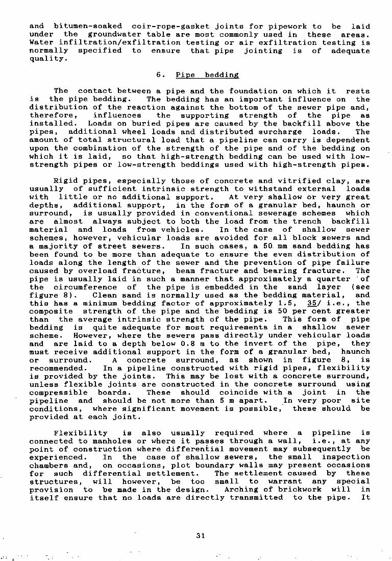
and bitumen-soaked coir-rope-gasket joints for pipework to be laidunder the groundwater table are most commonly used in these areas.Water infiltration/exfiltration testing or air exfiltration testing isnormally specified to ensure that pipe jointing is of adequatequality.
6. Pipe bedding
The contact between a pipe and the foundation on which it restsis the pipe bedding. The bedding has an important influende on thedistribution of the reaction against the bottom of the sewer pipe and,therefore, influences the supporting strength of the pipe asinstalled. Loads on buried pipes are caused by the backfill above thepipes, additional wheel loads and distributed surcharge loads. Theamount of total structural bad that a pipeline can carry is dependentupon the combination of the strength of the pipe and of the bedding onwhich it is laid, so that high-strength bedding can be used with bow-strength pipes or bow-strength beddings used with high-strength pipes.
Rigid pipes, especially those of concrete and vitrified day, areusually of sufficient intrinsic strength to withstand external boadswith little or no additional support. At very shalbow or very greatdepths, additional support, in the form of a granular bed, haunch orsurround, is usually provided in donventional sewerage schemes whichare almost always subject to both the bad from the trench backfillmaterial and boads from vehicles. In the case of shalbow sewerschemes, however, vehidular boads are avoided for all bbock sewers anda majority of street sewers. In such dases, a 50 mm sand bedding hasbeen found to be more than adequate to ensure the even distribution ofboads abong the length of the sewer and the prevention of pipe failurecaused by overload fraèture, beam fracture and bearing fracture. Thepipe is usually laid in sudh a manner that approximately a quarter ofthe dirdumference of the pipe is embedded in the sand bayer (seefigure 8). Clean sand is normally used as the bedding material, andthis has a minimum bedding factor of approximately 1.5, 35/ i.e., thedomposite strength of the pipe and the bedding is 50 per cent greaterthan the average intrinsic strength of the pipe. This form of pipebedding is quite adequate for moet requirements in a shalbow sewerscheme. However, where the sewers pass directly under vehicubar boadsand are laid to a depth bebow 0.8 m to the invert of the pipe, theymust receive additional support in the form of a granular bed, haunchor surround. A dondrete surround, as shown in figure 8, isrecommended. In a pipebine constructed with rigid pipes, flexibilityie provided by the joints. This may be lost with a concrete eurround,unless flexible joints are constructed in the concrete surround usingcompressible boards. These should doindide with a joint in thepipeline and should be not more than 5 m apart. In very poor sitedonditions, where signifidant movement is possible, these should beprovided at eadh joint.
Flexibility is also usually required where a pipeline isconnected to manholes or where it passes through a wall, i.e., at anypoirit of construction where differential movement may subsequently beexperienced. In the case of shalbow sewers, the small inspectionchambers and, on occasions, plot boundary walls may present occasionsfor such differential settlement. The settlement caused by thesestructures, will however, be too small to warrant any specialprovision to be made in the design. Arching of brickwork will initself ensure that no boads are directly transmitted to the pipe. It
31
1 2
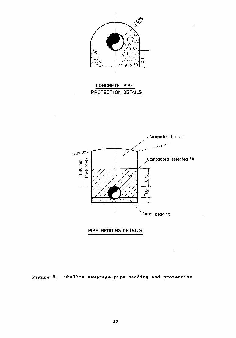
CONCRETE PIPEPROTECTION DETAILS
PIPE BEDDING DETAILS
selected t jil
Figure 8. Shallow sewerage pipe bedding and protection
Cornpocted back fili
Q
bedding
32
is, however, possible that, at some future date, an extension to anexisting building may be required to pass over a shallow sewer line.In such a case and in all similar cases where load—bearing walis arerequired to pass above existing pipelines, special precautions indesign are necessary. A joint should be provided in the pipelinewithin approximately 150 mm of the face of the structure, and, wherethe differential movement is likely to be appreciable, the length ofthe next pipe should be restricted to 600 mm and the structure aroundthe pipe suitably arched to reduce the direct bad on the pipe. It ishowever interesting to note that, in north—east Brazil, even where nosuch special provisions were made to protect the pipes as they passedunder load—bearing walls, no adverse effects such as pipe fracture andfailure were noted even after five years. Clearly, the nature of thewill, to a large extent, determine the need for the provision of pipeflexibility.
7. Inspection chambers
In shallow sewer systems, inspection chambers are provided alongblock and street sewers for the folbowing purposes:
(a) Connecting water closet and sullage house connections to thebbock sewer;
(b) Connecting block sewers to main street collector sewers;
(c) Providing access for purposes of cleaning and maintenance;
(d) Accommodating changes in direction in both bbock and streetsewers.
The depth to invert of a sewer at the point where an inspectionchamber is required will determine the dimensions of the chamber.Where the depths are shallow, usually up to 0.75 m, there is nonecessity for the physical entry to the chamber for purposes ofmaintenance. ilowever at, greater depths than this the chamberdimensions have to be such that the maintenance crew can physicallyenter the chamber. Since shalbow sewer schemes rarely exceed 2.0 m indepth, three types of inspection chambers have been designed,depending on the depth of the sewer they serve. The dimensions ofthese chambers are presented in table 2 and are also illustrated infigure 9. In the rare event that the depth of sewer exceeds 2.5 m, amanhole of the type commonly used for conventional sewers, may beprovided. A square form is usually adopted for the design ofinspection chambers for shalbow sewer systems; however, since, in mostdeveboping countries, split bamboo is the most common implement usedto remove bbockages, the use of a rectangular—shaped chamber (with thelarge dimension of the chamber being constructed abong the length ofthe sewer line) will facilitate rodding through the formation of agentle curvature on the rodding implement.
33

—~——
ff1
SECTION B-B
INSPECTION CHAMBER 1 C 2
IC 3
PLAN A-A 1 0 15 1
81 ~
n
PLAN A-A
-~-A
1 1020[ L J020[
Weok cementmortor seal
INSPECTION CHAMBER 1 C 2
PLAN D-D
2Omm mild steelstep ron
SECTION B-B
steel
1 1~~ lC 1
lC 2iC 3
DEPTH 10 SEW~RINVERT )m)
INSPECTION
SOUARE B e L
O4xOLmIO7XO7m
-
CHAMBER DIMENSIONS
1 RECTANGLE B x L 111]
UPTO 075 O4x06m075-135 1 O6xOBm
135-250 08 e12m
T--- T
SECTION C.-C
NSPECTION CHAMBER
Figure 9. Shalbow sewerage inspection chambers
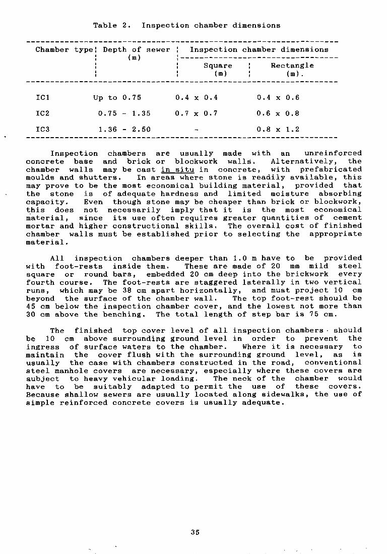
Tabbe 2. Inspedtion dhamber dimensions
Chamber type: Depth of sewer Inspection dhamber dimerisions(m) :
Square : Rectangle(m) (m).
IC1 Up to 0.75 0.4 x 0.4 0.4 x 0.6
1C2 0.75 — 1.35 0.7 x 0.7 0.6 x 0.8
1C3 1.36 — 2.50 0.8 x 1.2
Inspection chambers are usually made with an unreinforcedconcrete base and bridk or bbockwork walbs. Abternativeby, thedhamber wabbs may be cast in situ in condrete, with prefabridatedmoulds and shutters. In areas where stone is readiby avaibabbe, thismay prove to be the most economical buibding materiab, provided thatthe stone is of adequate hardness and bimited moisture absorbingcapacity. Even though stone may be cheaper than bridk or bbockwork,this does not nedessarily impby that it is the most edonomidabmaterial, sinde its use often requires greater quantities of cementmortar and higher donstrudtionab skills. The overall doet of finishedchamber walls must be established prior to sebecting the appropriatemateriab.
All inspection chambers deeper than 1.0 m have to be providedwith foot-rests inside them. These are made of 20 mm mild steelsquare or round bars, embedded 20 cm deep into the brickwork everyfourth course. The foot-rests are staggered baterabby in two verticabruns, which may be 38 cm apart horizontally, and must project 10 cmbeyond the surface of the chamber wall. The top foot-rest should be45 dm bebow the inspedtion chamber cover, and the bowest not more than30 cm above the bendhing. The total bength of step bar is 75 cm.
The finished top cover bevel of all inspedtion chambers shouldbe 10 cm above surrounding ground level in order to prevent theingress of surfade waters to the chamber. Where it is necessary tomaintain the cover flush with the surrounding ground level, as isu~ualby the case with chambers constructed in the road, conventionalsteel manhole covers are necessary, especially where these covers areaubjedt to heavy vehicubar boading. The neck of the dhamber wouldhave to be suitably adapted to permit the use of these covers.Bedause shabbow sewers are usually bocated abong sidewalks, the use ofsimple reinforced condrete covers is usuably adequate.
35

III. SHALLOWSEWERPLANNING AND IMPLEMENTATION STRATEGIES
The strategies to be adopted in planning and impbementing shabbowsewer systems will, to a large extent, depend on the nature and age ofthe settbement. Existing, unplanned, often illegal, bow-indomesettbements necessitate far more effort at both the pbanning andimplementation stages than newly-pbanned sites—and-services or bow-income housing schemes, where shalbow sewers may be introduded as oneof the servides provided. In both cases, however, the success of thesanitation system relies on invobving and informing the benefidiarydommunities of the various aspects of the design and operation of thesystem.
A. Projedt area and drainage basin
The first step in pbanning a shabbow sewer system is theestablishment of the project area and assodiated natural drainagebasins to whieh it conforms. This is usuably done by delineating theboundaries on a 1:10,000 map with contours every 5 m. All planning ofshallow sewer systems is undertaken according to natural drainagebasins. Frequentby, the entire settiement or project area conforms tothe bourids of a single natural drainage basin, but where this is notthe case parts of the projedt area conforming to different drainagebasins can be considered in isolation for purposes of estabbishingsewer layouts and for organizing the community to partidipate in theprogramme.
Even for subsequent treatment of dobbedted sewage, it is oftenadvantageous to donsider the use of separate treatment units fordifferënt drainage basins. However, the economics of adopting asingle treatment unit, with suitably designed pumping stations todeliver the sewage from the different basins to a common point, mustbe assessed. Pumping may become inevitabbe in congested urban areas,in order to deliver sewage to a selected area for treatment, unlessaccess to a nearby sewer exists. Although the project area may formonly part of the total area of a natural drainage basin, perennial ornon—perennial tributary water courses draining the basin may be usedto dispose of treated effbuents.
B. Physicab surveys
In order to prepare detaibed street sewer layouts, maps of thearea to be served are required at a scabe of 1:2000. The map shouldshow ebevations (by means of dontours every metre), roads, buildings,property boundaries and other pertinent information. Informationregarding the geology and hydrogeobogy of the area may also berequired, in order to .sebect suitable treatment sites and makeaddurate estimates of the dost of the schenre. While these preliminarysurveys can be conducted without the assistande or do—operation of thecommunity, a sedond survey which relies on sudh participation willhave to be undertaken, in order to establish the layout of the blocksewers. Because the bbock sewers invariabby pass through individuabproperties, usually at the back of the house, community donsent andco-operation are essential, initially to establish the bocation of theblQck sewers and inspection chambers and subsequentby to obtain theelevations abong the seledted route.
Pbans must be prepared for every blodk at a- sdale of 1:500,indicating each house, building and property boundary. When eachhouse has been visited, and the householders’ preferred bodation for
36

the inspection chamber within each plot has been established, atopographical survey is conducted to establish the elevations ofinspection—chamber locations. The block sewer layouts can then bemade on the bbock map. In highly congested unplanned areas, spotlevels of the proposed inspection chamber locations can only beobtained by utilizing stilte to support the surveying equipment, inorder to obtain the necessary line of vision above boundary walis forlevel readings.
C. Sample socio—edonomic survey
It is often the case in low—income housing settlements that verylittie information will be available regarding the types of servicesprovided, plumbing equipment used, water availability and usagepatterne, and household payment capacities — all essential informationfor planning and designing block sewers. In such cases, it isnecessary to conduct a sample domestic survey to elicit suchinformation and also provide some indication of the beneficiaries’preferences and priorities. Commonly, a minimum sample size of 7 percent of the project population is used to obtain statistically validinformation.
The nature and structure of the questionnaire will vary from oneproject site to the next, but basic information, usually crbtained fromformal questionnaires, includes the following:
(a) Type of occupation of the house (rented, owned etc.);
(b) Type of housing and its bocation within the compound;
(c) Origin and size of family;
(d) Income and occupation;
(e) Levels of services and corresponding payments;
(f) Nature of facilities, including plumbing and sanitary
fixtures, and water usage patterns;
(g) Present modes of excreta and sullage disposal;
(h) Preferences for sanitation systems;
(i) Deficiencies - in the provision of services in the area and
order of priority for resolving them.
The information obtained is usually structured in the form of aquestionnaire that conforms with the general prinQiples of “heuristicelicitation”, i.e., each -question isbased on the answer of theprevious question so that they are respondent-generated rather thaninvestigator—generated and are, thus, minimally affected byinterviewer bias. Additional information on the design andapplication of suitable socio—economic survey questionnaires togetherwith sample formats are presented elsewhere. ~j~j~3j
D. Institutional reciuirements
The nature of shallow sewerage demands that some local authority,usually the municipality or the water authority, be entrusted with theresponsibility for designing and implementing the scheme. However,very few of these institutions have had any practical experience in
37

working with the communities they serve by involving them at thestages of technobogy seledtion design, construdtion and operation, asis required for shallow sewer schemes. It may prove necessary todreate a spedial technical unit within existing institutions, in orderthat adequate training can be provided to the staff to ensure thesuddessful delivery of this community—based sanitation system.
An alternative approadh, whidh has had some success, is toentrust the tasks of mobilizing local communitities and of executingthe blodk sewers to non—governmental organizations (NGOs), while co—
ordinating the overall scheme under the lodal authority which alsoremains responsible for executing the main collector sewers to whichthe individuab block sewers drain. It is often possible to make adistinction between the blodk sewers and the street collector sewers,because the members of the community of ten prefer to maintain thebloek sewers themselves. Thus, only the external sewer needs to bemaintained by the authorities.
The involvement of NGOs is particularly useful when the entirecapital oost of the scheme needs to be raised prior to initiatingconstruction. However, given the scale at which most shallow sewersdhemes are implemented, the capital cost of the system is usually metby some form of government ban which, together with the cost ofoperation and maintenance, is recovered through a monthly tariff,often represented as a perdentage of the water tariff. All liftstations and sewage treatment plants will naturally come under thejurisdidtion of the local authority.
E. Community involvement in construction of shalbow sewers
Whatever the organizational pattern of the agendy entrusted withthe programme, planning, construction and operation of shallow sewersrequire extensive dommunity involvement, acceptance and participation.Based on the findings of the sample survey and when funds have beenalbocated for the scheme, promotional activities must be undertaken,with the objective of introducing the sanitation programme to thecommunity. Community leaders should be initially identified andinformed of the benefits of the programme, and the need to stimulatethe partidipation of all community members emphasized.
With the consent and involvement of the leaders, generalcommunity meetings can be donvened, to explain the programme andobtain the agreement of the householders to conduct door—to—doorsurveys. These will establish the location of existing plumbinginstallations and the householders’ preferred locations for theiflspedtion chambers to be constructed within their premises and thedorresponding elevations. A brief description of the shalbow sewerconcept is presented to the community at the meetings, together withits advantages and disadvantages. Small—sdale physical models aresometimes used to help dommunities understand the system.
At the end of the first meeting, the project staff agrees withthe community to undertake the following:
(a) Arrange individual meetings for each block to present aproposed blodk sewer layout based on the physical, topographical anddoor—to~-door surveys condudted. (The layout is usually presented on a1:500 map showing all buildings, boundary wabls and bbodk sewers andinspection dhambers.)
38
(b) Obtain cont~nt on the proposed layout for the block sewers.
(c) Obtain agreement as to the delineation of responsibilitybetween the dommunity and the authorities. (Community responsibilityfor operation and maintenance of the block sewers keeps down costs andensures that the system is not abused. Each houeehold is usually maderesponsibbe for that length of sewer passing through its property. Afeeling of obligation to one’s neighboure is usually instilbed throughdiscussions at these meetings. Street dolledtOr sewers are usualbymaintained by the local authority.)
(d) Present estimates of the cost of the system and obtainagreement on the amount and mode of repayments, usually in the form ofa monthly tariff.
Agreement is also obtained from the community to provide freeaccess to its properties to projedt staff and to survey and donstruc—tion teams.
Even if majority consent is given on all the above issues, it ispossible that some community—group pressure and persuasion will berequired to ensure that all househoids participate, in order that theoverall dosts may be minimized and the health impadt of theintervention maximized. It ie also possible that some doubts mayarise in the minds of dommunity members as to the tedhnidal and socialfeasibility of the system, especially with regard to blockages whichcould lead to gross nuisance within their premises. The construdtionof a single bbodk sewer serving an entire bbock may be implemented asa pilot scheme to demonstrate both the technical and sodialfeasibibity of the shalbow sewer system. (The sewage drained from thepilot blodk may be treated in a dommunal septic tank and disposed ofthrough infiltration trendhes.) Onde the pilot sdheme has been shownto operate without problems, and other members of the projectdommunity are able to discuss the benefits and problems of the systemwith those served by the scheme, the pilot sdheme itself acts as the -main motivating force in creating adceptance of and a demand forshallow sewers.
Since the blodks are seen as the basic units of socialorganization, all sewer layouts within the block are established inconsultation with the community. The blodk layouts subsequentlydetermine the final layout of the street sewers. When the invertlevels of all bbock sewers emerging from the various blocks in theproject area are known the street colledtor sewer layout may beestablished with its corresponding elevations.
Construdtion is first initiated with the implementation of thestreet collector sewers and treatment works. Bbodk sewers aresubsequently connected, according to priorities established by thecommunity. All house connections are then made to the respective bbocksewers. The entire system is thoroughly tested before dommissioning.The involvement of the community at all stages ensures a very highpercentage of house donnections and a level of sanitation servicewhich is in no way inferior to that of conventional sewerage.
The implementation of the block sewer usually nedessitates a dayor two in each house for purposes of donstrudting the sewer,inspection dhamber and associated house connections. This work isoften conducted by small subcontradtors and supervised by localauthority technicians trained spedifidally for this purpose as part ofa special unit created for the execution of shalbow sewer systems.
39
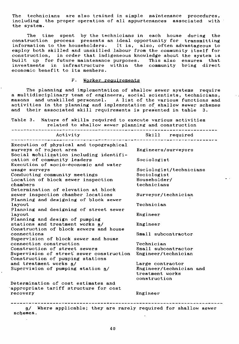
The technicians are also trained in simple maintenance prodedures,indluding the proper operation of all appurtenandes assodiated withthe system.
The time spent by the technicians in each house during thedonstrudtion process presents an ideal opportunity for transmittinginformation to the householders. It is, also, often advantageous toempboy both skibbed and unskibled labour from the community itsebf forconstruction, in order that indigeneous knowledge about the system isbuilt up for future maintenance purposes. This also ensures thatinvestments in infrastructure within the community bring diredteconomic benefit to its members.
F. Worker reguirements
The planning and implementation of shalbow sewer systems requirea multidisciplinary team of engineers, social scientists, tedhnicians,masons and unskilled personneb. A list of the various functions andactivities in the planning and implementation of shalbow sewer sdhemesand their associated skill requireinents is presented in table 3.
Table 3. Nature of skills required to execute various adtivities
related to shalbow sewer planning and construction
Activity Skill required
Execution of physical and topographicalsurveys of roject areaSodial mobilization including identifi-cation of community leadersExecution of socio—economic and waterusage surveysConducting community meetingsLocation of block sewer inspectiondhambersDetermination of elevation at blocksewer inspection chamber bocationsPlanning and designing of block sewerlayoutPlanning and designing of street sewerlayoutPlanning and design of pumpingstations and treatment works a/Construction of bbock sewers and houseconnectionsSupervision of bbock sewer and houseconnedtion constructionConstruction of street sewersSupervision of stree� sewer donstructionConstruction of pumping stationsand treatment works a/Supervision of pumping station a/
D~termination of cost estimates andappropriate tariff strudture for costrecovery Engineer
a/ Where applicable; they are rarely required for shalbow sewerscbemes.
Engineers/ surveyors
Sodiobogist
Sociologist/techniciansSociobogistHouseholderjtechnicians
Surveyor/ tedhnician
Tedhnidian
Engineer
Engineer
Small subcontradtor
TedhnidianSmall subcontractorEngineer/technician
Large contractorEngineer/technidian andtreatment worksconstruct ion
40
A majority of the duties associated with the design of shalbow sewerschemes requires only a bow-level cadre of technicians: overallsupervision by qualified engineers and sociologists will, however, benecessary. The simple nature of moet of the construction associatedwith shalbow sewers means that small (local) subcontractors may beengaged for implementing the system, instead of large constractors asis usual with conventional sewerage. The reduced overheads associatedwith small contracting companies reduces the overall cost of thescheme considerably and offers potential for engaging local communitymembers in the construction process. Attempts by many authorities toemploy direct labour for construction have proved to be inefficient,and this is therefore not usually recominended.
G. Project drawings
Simple engineering drawings are produced to facilitate theconstruction of shalbow sewer systems. They include:
(a) A map of the project •area, showing elevations by means ofcontours distributed every metre, existing roads, buildings, propertyboundaries etc., upon which is superimposed the location of streetsewers, suitably referenced, and all road inspection chambers alongits length. (A scale of 1:2000 is usually adopted for this purposealthough, in congested areas, a scale of 1:1000 may be moreappropr;iate - see figure 14.)
(b) A second layout plan showing the street sewers with theircorresponding reference numbers, lengths, pipe diameter, gradients andbedding details, and the ground and pipe invert level information ateach inspection chamber (see figure 14). (Usually house and streetlayout lines are omitted from the second drawing, eliminating the needto produce bongitudinal cross sections of the sewers, since all theinformation can be readiby abstracted from this second plan.)
(c) A plan of ~ach block of houses, usually to a scale of 1:500,showing the layout of each bbock sewer and inspection chamber abongits length in relation to the position of each house and propertyboundary. (In the case of a planned low-income housing scheme atypical layout plan would be adequate, but, in unplanned settlements,It is necessary to prepare a specific plan for each block — see figure15.)
(d) A typical plan and appropriate sections depicting houseconnections and plumbing installations to an acceptable scale,usually 1:50.
(e) Plans and eections of inspection chambers and sectionsshowing pipe bedding and trench exoavation to suitable scales (seefigures 8 and 9).
(f) Plans and sections of sewage pumping and treating facilities.
41

IV. CONSTRUCTIONAND MAINTENANCEOF SHALLOWSEWERS
The techniques used for the construction of shalbow sewers arethe same as those used in conventionab sewerage, except that, owing totheir shabbow depth and the use of small subcontractors for theirconstruction, simple methods of maintaining horizontab and vèrticalcontrobs and ensuring quabity in construction have been deveboped tominimize costs whibe stibi achieving acceptabbe standards. These andother measures necessary for maintaining construction quality controland preparing construction cost estimates are presented in thischapter. Requirements and procedures for maintaining shalbow sewersystems are also incbuded.
Usuabby, construction begins at the treatment and disposabfacibities, with the street sewers being laid next, in the upstreamdirection, before finabby construction of the bbock sewers and houseconnections. The construction of the bbock sewers, generably throughprivate property boundaries, presents certain problems of a sociabnature that can onby be overcome by active community participation andunquabified community acceptance of the system. Constructionprocedures shoubd, therefore, be designed so as to create the beastinconvenience to househobders.
A. Bbock and street sewer instalbation
1. Prebiminary layouts
The construction of bbock sewers for a new housing schemepresents fewer probbems than their construction in existing unplannedsettlements. In the batter oase, the community must be kept informedand must participate at every stage of planning and construction, andits agreement on all proposabs, incbuding sewer layouts and mode ofconstruction, must be obtained and respected. During the initialplanning stage, when house calls are made to establish thehousehobders’ preferred bocations for the inspection chambers, woodenstakes or pegs are used to mark the exact bocations. The sewersfobbow a binear abignment between the pegs or inspection chambers.The street sewers require some consultation with the community toestabbish layouts and construction methods, but they are, generalby,determined in relation to the emerging bbock sewers. Pegs aregeneralby used to mark the bocation of inspection chambers abongstreet sewers.
2. Setting line and grade
The line of the sewer shoubd fobbow, as far as possible, thatwhich was estabbished during the design and agreed with the community.The centre line of the trench must usuably coincide with the centre.bine of the sewers between adjacent inspection chamber pegs.Benchmar1~s estabbished within the bbock and abong streets are usedfor sewer line and grade control.
It has proved adequate to control bevebs by the use of a simplemason’s barometric bevel. The barometric level is composed of asimple transparent plastic tube (usuabby 5 mm in internab diameter)open at both ends and filled with water in such a way that, when heldin the form of a U-tube (the normab position of use), it has asufficient column of air above the water surfaces in each beg of thetube. The two begs of the tube are held against metre rubes pbaced atthe two points whose difference in bevel is required. Since the water
42
levels in each leg of the tube are at a constant elevation, becausethey are both subject to atmospheric pressure, the difference in theheights of water dolumns in each, as read from the metre rules,represents the difference in level between the two points upon whichthe metre rules were placed. An iblustration of this simple beveldevide is presented in figure 10. This form of level instrument isespecialby useful in controlbing and establishing sewer grades inexisting unplanned settlements where the construction of the bbpcksewer often requires the partial demolition of boundary walis duringconstruction. The level can be passed through the portion of walldemobished for trench excavation to obtain the bevel differencebetween adjacent inspection chambers, and where more conventionalsurvey instruments could not be used due to the obstrudtion of theinstrument’s line of sight by the intervening wall. Conventionallevel instruments have, however, been adapted for this purpose byplacing them on stilte and using a step ladder to obtain instrumentreadings.
When the required difference in leveb between adjacent inspectionchambers has been estabbished, the constant sewer grade requiredbetween them is ensured by placing a taut piece of string between thetwo points at a height above the pipe bedding equivalent to theexternal diameter of the pipe socket, in such a manner that the topsurfaces of all laid pipe sockets would be just in contact with thestring. In determining the required trench Invert depth for pipelaying and inspection chamber construction, ablowances must be madefor pipe wall thickness and depth of bedding, and for inspectiondhamber base and benching. Where automatic or other bevel instrumentsare used to obtain the depth and sbope of the bottom of the trenchesand the levels of the inverts of pipes, the usual method of sightrails and boning rods (or travellers) is empboyed. Street sewers areusualby set out and graded by this method.
3. Excavation
Extreme care is necessary to bodate and protect existingutilities and foundations of structures. Care must also be taken toensure that boundary walls, when partby demobished to facibitate sewerconstruction, are broken in an arched form, straddbing the trench, inorder to avoid dradking and doblapse. All demolitions must be madegood upon dompletion of sewer baying. Sides of excavation wabbs maybe vertidab, in favourabbe ground conditions, or inclined at asuitable angle of repose, when excavated deep in unfavourabbe ground.The width of the trench must permit the laying of pipes with ease andadcurady, and, abthough the width of the trench wibb vary with thetype of soil and ground condition, the values presented in tabbe 4serve as a useful guide for both cost estimation and control to avoidover—excavation.
Excavation is usually performed manually, - but, where rock isencountered, some mechanicab assistance may prove useful. The shalbowdepths to which excavation is usualby performed for shabbow sewersystems impby that there is little need for trench support apparatus,but, when the depth of excavation is such that the soil type does notprovide sufficient safety against trench cobbapse through caving in,the sides of the trench should be supported by timbering. Timberingconsists of vertical poling boards supported by wabing boards, placedhorizontabby and at right angles and securely held in place withhorizontal struts, fixed across the trench about 2 m apart. Thedistance apart of poling boards and waling boards depends upon the
43

d
Metre Rule
h1
h2
Transparent plastictube
~1~
Gradienth -h
L~ 2 1d
Figure 10. Barometrjc level

booseness of the soib to be supported: the bottom set of pobingboards shoubd be driven at beast 230 mmbebow the trench-bed bevel.The trench shoubd be sufficiently wide to abbow space for timbering:a space of 150 mm tp 230 mm on either side of the body of the sewer isconsidered sufficient. Steéb (or wooden) interbocking sheet pibes areused where water or running sand is encountered.
Tabbe 4. Approximate trench widths for different pipedepths and diameters
Pipediameter Depth to pipe invert (m)
(mm)
Up to 0.6 0.6—1.0 1.1—1.5 1.6—2.0 2.1—2.5
100 0.40 0.50 0.65 0. 70 0.75
150 0.45 0.60 0.70 0. 75 0.80
200 0.50 0.70 0.75 0. 80 0.85
4. Pipe beddint and backfibbing
Depending on the depth of pipe laying and expected superimposedboads on the pipe, one of the types of pipe bedding suggested inchapter II is required. Where rock is encountered, the sand cushionusuabby provided throughout the bength of shabbow sewers normabbyproves to be adequate bedding. In some grounds, where the finishedsurface of the formation becomes soft after bevebbing, a firm bottommay be obtained by spreading and compacting a 75 mm bayer of graveb orbroken stone over thè trench bottom which shoubd be further excavatedto receive this. Excess excavations shoubd also be simibarby fibbed,and the trench bottom levebbed to the appropriate grade. Extraexcavation is required under sockets, to albow hands to pass formaking joints and to ensure that the body of the pipe is suitabbysupported on the bedding. Backfibling materials shoubd be free fromstones, hard materiabs, waste, objectionabbe organic matter, rubbishand boggy or other unsuitabbe materials. Such sebected materiab mustextend to 300 mm above the top of the pipe and across the full widthof the trench. Backfibbing must be done in 230 mm bayers thoroughbyrammed, and excessive watering should be avoided. Excess backfibbingto form a dome shaped surface above the trench is desirabbe to takeaccount of future settbement.
5. Laying and jointing pipes
Each pipe should be carefubby examined for soundness beforebaying: concrete and clayware pipes should be rung with a lighthammer, and those that do not ring true and dear shoubd be rejected.All sewer pipes are baid with the socket at the higher end, and,consequentby, it is necessary to begin at the bow end of a drain andto work upwards. Bad pipe jointing is the cause of a majority of pipe
45
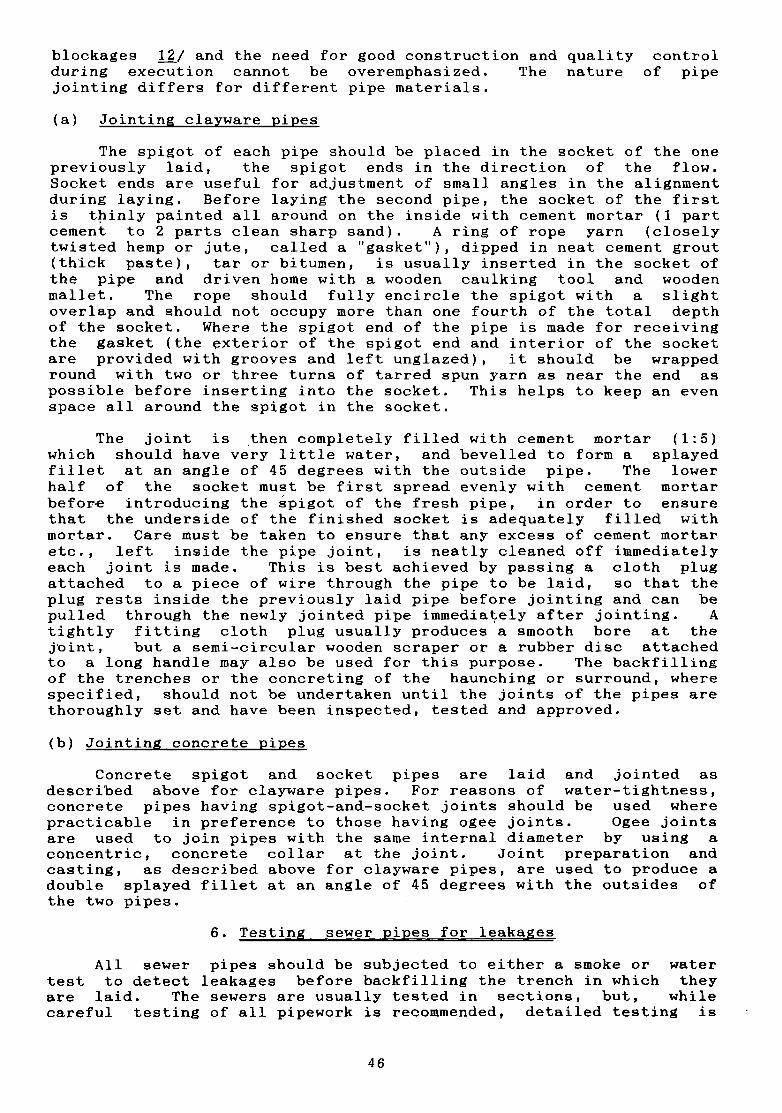
blockages 12/ and the need for good construction and quality dontrolduring exedution cannot be overemphasized. The nature of pipejointing differs for different pipe materials.
(a) Jointing clayware pipes
The spigot of each pipe should be placed in the socket of the onepreviously laid, the spigot ends in the diredtion of the fbow.Socket ends are useful for adjustment of small angles in the alignmentduring baying. Before laying the second pipe, the socket of the firstis thinly painted all around on the inside with cement mortar (1 partdement to 2 parts clean sharp sand). A ring of rope yarn (dboselytwisted hemp or jute, called a “gasket”), dipped in neat cement grout(thick paste), tar or bitumen, is usually inserted in the socket ofthe pipe and driven home with a wooden caulking tool and woodenmalbet. The rope should fulby encircbe the spigot with a slightoverlap and should not occupy more than one fourth of the total depthof the socket. Where the spigot end of the pipe is made for receivingthe gasket (the exterior of the spigot end and interior of the socketare provided with grooves and left unglazed), it should be wrappedround with two or three turns of tarred spun yarn as near the end aspossible before inserting into the socket. This helps to keep an evenspace abl around the spigot in the socket.
The joint is •then dompletely filbed with dement mortar (1:5)which should have very bittbe water, and bevelled to form a splayedfiblet at an angbe of 45 degrees with the outside pipe. The lowerhalf of the socket must be first spread evenly with cement mortarbefore introducing the spigot of the fresh pipe, in order to ensurethat the underside of the finished socket is adequately filled withmortar. Care must be taken to ensure that any excess of cement mortaretc., left inside the pipe joint, is neatly cleaned off immediatelyeach joint is made. This is best achieved by passing a cboth plugattached to a piece of wire through the pipe to be baid, so that theplug rests inside the previously laid pipe before jointing and can bepulled through the newly jointed pipe immediately after jointing. Atightly fitting cloth plug usualby produces a smooth bore at thejoint, but a semi-circular wooden scraper or a rubber disc attachedto a long handbe may also be used for this purpose. The backfillingof the trendhes or the concreting of the haunching or surround, wherespecified, should not be undertaken until the joints of the pipes arethoroughly set and have been inspected, tested and approved.
(b) Jointing condrete pipes
Condrete spigot and socket pipes are baid and jointed asdescribed above for clayware pipes. For reasons of water-tightness,concrete pipes having spigot-and-socket joints should be used wherepradtidable in preference to those having ogee joints. Ogee jointsare used to join pipes with the same internab diameter by using aconcentric, concrete coblar at the joint. Joint preparation andcasting, as described above for dlayware pipes, are used to produce adouble splayed fillet at an angle of 45 degrees with the outsides ofthe two pipes. -
6. Testing sewer pipes for leakages
All sewer pipes should be subjected to either a smoke or watertest to detect leakages before badkfilbing the trendh in which theyare laid. The sewers are usually tested in sedtions, but, whiledareful testing of all pipework is recommended, detailed testing is
46
usually only performed for street sewers. Many shalbow sewer systemslaid with simple cement mortar pipe joints, without gaskets andwithout any detailed testing procedures, have operated verysatisfactoriby for over five years.
(a) Smoke test
Smoke is made by firing oily waste (brown paper or cotton wastesoaked in creosote), and the smoke is pumped into the pipework at thebower end with the aid of a smoke—testing machine. Smoke rockets mayalso be used for this purpose. Inadequateby seabed joints wibb beseen to issue smoke when the opposite end of the pipework is plugged.The defedtive joints must then be repaired until they stop issuingsmoke.
(b) Water’ test
After the joints have properly dried (usually after 48 bours butidealby after seven days) and before backfilbing of trenches, thepipes may be tested for watertightness by fibling the pipes with waterto a level 1.5 m above the top of the highest pipe in the length to betested by dlosing the opposite end and maintaining this water bevelfor one hour. Water is introduced through a funnel fixed to a rightangle bend at the top end of the pipework by means of a rubber tube.When air bubbbes have escaped after the initial filbing and absorptionhas deased, water is again added to fill the pipe. A sbight amount ofsweating, which is uniform, may be overbooked, and a small amount ofsubsidende should not be taken as implying bad workmanship or defects.
A toberance figure of two litres per cm diameter per kibometremay be abbowed during a water-fibled period of 10 minutes.Alternatively, if the water level does not fali more than about 14 mmin a length of 100 m, this may be considered satisfadtory. The waterput in the pipes for testing should not be drained out until thetrenches have been filled in completely (for shalbow trendhes) or toabout 90 ~m (in deep trenches), to detect if any joints have given wayduring backfilling.
B. Inspection dhamber instablation
Depending on the invert level of the sewer at the point where aninspection dhamber is required, one of the three types of inspectionchambers specified in table 2 will be provided. Unreinforced concrete(1:3:6 mix) is usually provided for the base of the chamber, whilereinforced concrete is used for the cover. Depending on whether thecover is for a dhamber to be pladed in private or publid property, thepredast reinforced doncrete covers are made of 1:3:6 and 1:2:4 mixrespectiveby. Walbs of the inspection chambers are of differentthickness for different types of dhambers, and must be maintainedplumb vertical. The walls are usually of brickwork or dementbbockwork, made with dement mortar (1:8) and plastered smoothly on theinside with cement mortar (1:5). Where saturated soib is encountered,the plaster should be also applied on the outside up to a height of 30cm above the highest subsoil water bevel. Excavations for inspedtionchambers should have 30 cm cbearance on all sides.
The bottom of inspedtion chambers should be adequately “benched”,to have a fabl towards the invert of about 1 in 6. The benchingshoubd be at beast as high as three quarters of the diameter of theoutgoing pipe, and should be floated to a smooth surface with cementplaster (1:2). In the case of branch drains, the benching should be
47

so shaped round the channel branches as to guide the flow of sewage inthe desired direction. Channebs of at least half the diameter of theoutgoing pipe shoubd be provided at the base to which all benchingmust fall. Channels must also be suitably plastered with cementmortar (1:2) and finished smooth, and the ends of channels should fitsewer ends accurateby. Branch sewers and house connections may beconnected at the level of the chamber channel or benching, or, wherenecessary, at some point in the chamber wall. The shabbow depths towhich sewers are usualby lald in shalbow sewer systems impby that dropconnections are not required. In deep inspection chambers, all pipesexceeding 150 mmdiameter passing through the chamber walls shouldhave an arched form over them in order to relieve the pipe of theweight of the wall above. All foreign materials, such as excesscement mortar and sand, should be removed from the chamber base-before commissioning.
C. As—constructed drawings
At the end of all construction work, the complete system must beillustrated on detaibed as-constructed plans, similar to thoseproduced originalby for construction. The actual depths and locationsof sewers and the location of each inspection chamber must bespecified on these plans.
D. Maintenance of shalbow sewers
Shalbow sewers requlre very little maintenance: the only routinemaintenance which must be performed is the removal of grit and greasefrom individual household grit/grease chambers. Routine flushing ofthe sewer bines, both block and street sewers, has not been necessaryin any of the systems currently in use, and periodic flushing has notbeen necessary even in areas where water consumption is bow. Goodquality control during construction, especially in the execution ofpipe jointing, and the prevention of extraneous matter gaining accessto the pipes are two important measures for reducing to a minimum themaintenance required on shalbow sewer systems.
The responsibility for operating and maintaining shallow sewersystems is usualby divided between the community and the localauthority (e.g. , municipality or local water and sewerageorganization). The community is usually entrusted with responsibilityfor maintaining the house connections and bbock sewers, while thelocal authority remains responsibbe for the external street sewers,sewage disposal facilities and ancillary works. The benefits ofcommunity participation in sewer operation and maintenance is oftenreflected in terms of reduced sewerage tariffs. Agreement from eachhouseholder to operate and maintain all house connections to thesystem, the inspection chamber and that length of bbock sewer bocatedwithin his premises is obtained during the block community meetings.Where possible, such agreement is obtained and maintained in goodfaith between the community and the authority, but the legalramificatlons of the agreement may also be spelt out on an officialagreement form to be signed by each household member requesting aconnection to the system. Where the latter approach is adopted, theconstruction of the bbock sewers may be initiated only when anadequate number of signed requests have been obtained. In cultureswhere the community members cannot, for religous or other reasons,perform such simple maintenance tasks as unblocking of the sewerpassing through their premises, this work is usually entrusted to aspecialized group of persons who can undertake such work and whoshould be trained in the appropriate maintenance procedures by the
48

local authority. In any event, sufficient information should betransferred to the community, during the construction process, toensure that its members are fully informed on the proper operatlon andmaintenance of the bbock sewers.
Blockages in properly constructed shalbow sewer systems are veryrare. When they do occur, however, they are readily removed by usinglong lengths of split bamboo or any other commercially availablerodding device. Location of the blockage, however, may require somecommunity co-operation. The bbockage may be bocated by opening allinspection chambers along the bbock sewer line until two adjacentchambers are found where the upstream chamber is fibled with sewagewhile the dowmstream chamber is dry. Rodding may be performed fromeither end, although rodding from the downstream end usuably resubtsin creating splash spillage at the chamber, as the sewage underpressure is abbowed to fbow through It. Some form of simple screenlngdevlce, e.g., chicken mesh wire, is used to cover the downstreamoutlet In order to trap the object which created the bbockage.Besldes simple rodding devices, any of the modern mechanized devicesmay be used for cleanlng sewer bbockages. Where bbockages have beencaused by sewer failure, the length of failed pipe must be replacedand, depending on the cause of failure, provided with suitable pipeprotection to avold future faibure.
49

V. PROJECT COSTS, APPRAISAL AND AFFORDABILITY
Compared with conventional sewerage, shalbow sewer systems areslgnifican-tby lees costly to construct and operate, and yet provide asimilar level of service. Depending on the density of settbement,shalbow sewer systems can also be less costly than on—site sanitationsystems, whibe providing a means of disposing of household sublage.The various material and construction costs which comprise the overallcost of sha].bow sewer schemes are considered in this chapter, togetherwith methods of project appraisal which permit the domparison ofshablow sewer schemes with other forms of sanitation. Methode ofdetermining affordabibity through financiab costings are alsoreviewed.
A. Project costs
Shallow sewer project costs are composed essentially of the
folbowing:
(a) Cost of planning and supervision;
(b) Cost of house connections, bbock and street sewers andappurtenances;
(c) Cost of pumping stations (where necessary), sewage treatmentfacibities etc.
1. Planning, design and supervision
These coets vary wIdely from project to project, since the costof planning, designing and supervising the construction of shalbowsewer systems for new bow—income housing and sites—and—servicessc~hemes is far lees than the corresponding oost of instalbing thesesystems in existing unpbanned settlements. However, the oost ofundertaking surveys and investigations, preparing the design,mobilizing the community and supervising construction is usually foundto lie within the range of 2 to 8 per cent of the oost ofcons-truction, including the bbock and street sewers and sewagetreatment facibities.
2. House connections, bbock and street sewers and appurtenances
The oost of house connections is composed of the cost of layingthe pipes connecting the water cboset, the grlt/grease trap and anyother direct sulbage connections to the inspection chamber. Wherewater cboset pans or seats are not already available, the coet ofsuppbying and instabling these and the grit/grease traps may also beincluded in the doet of house connections. The items of work to beconsidered in preparlng bilbs of quantities and estimating the overalloost of house connections are presented in table 5. Similarly, itemsof work to be considered for bbock and street sewers are presented intable 6. To the costs derived from tabbes 5 and 6 are added thefolbowing:
(a) Initial cost of setting up construction slte office;
(b) Final cleaning-up of eite after construction;
(o) Preparation of as—oonstructed drawings;
(d) Other misoellaneous oosts.
50
Tabbe 5. Construotion work associated with house oonneotione
Item Unit
Supply and f ix WC pan or seat NumberPipe trenoh exoavation:— in soil (class 1). m3- In soft rook (olass 2). m3- in hard rook (olass 3). m3
Supplying and laying PVC or AC pipework:- ‘75 mm diameter m- 50 mm diameter m- 38 mm diameter m
Suppbying and fixing grit/grease trap NumberSupplying and fixing ventilation column(75 mm diameter) and associatedT-oonneotion Number
Table 6. Construotion work assooiated with blook and
street sewers
Item Unit
Purohase and suppby day or concrete pipes:100 mm diameter m150 mmdiameter m200 mm diameter meto..
Pipe trenoh exoavation:In soil (olass 1) m3In soft rook (olass 2) m3In hard rook (olass 3) m3
Removing and making good existlng surfaoes:Roads m2Footpaths m2Concrete surfaoes m2
Demolishing and making good partition walls m2Pipe laying and jointing mPIpe beddIng and surround:
Sand m3Concrete (1:3:6) m3
Baokfibling of pipe trenohes m3Construotion of Inspeotion chambers:
Type IC1 NumberType 1C2 NumberType IC3 Number
51

Pumping stations are rareby required for shabbow sewer systems,but, where they are required, thelr oost must be established andinoluded in the overall oost of the soheme. The oost of sewagetreatment faoilities will depend on the form of treatment to beprovided. Where waste-stabilization ponds are used, Brazibianexperlenoe suggests that the oost of this form of treatment variesfrom 30 to 40 per cent of the total oost of the scheme. Detaibedbibls of quantitles will, however, be required to determine the oostof treatment which must then be inoluded as part of the overall oost.
8. Project appraisal
Having identified teohnioally feasible options for sanltation, ItIs necessary to make an objeotlve oomparisorî whioh resubts in theseleotion of the moet cost-effective one. Whlbe the final seleotionof the most appropriate sanltatlon teohnology should be left to theoommunity or its representatives, the basis for sebeotion is oftenthat of oost oomparisons refbeoting both the positlve and negativeoonsequenoes of choosing eaoh sanitation option. -
There is no completely satisfaotory method by whloh this may beachieved. Eoonomio benefit—oost anabysis is often used for thispurpose and aims to quantify the soolal advantages and disadvantagesof eaoh ohoice In terms of a common monetary unit. Whibe benefits mayeither be positive or negatlve (an exampbe of negative benefit is theinorease in water use ~or flushing that results from the provision ofsewerage systems), It is however Impossible to quantify many of thepositlve benefits, suoh as improved health, greater welb-being, higherproductivlty eto., resulting from improved sanitation. Eaohalternative oonsidered could give different benefits and, since inmany oases the benefits remain unquantifiable, inooneistenoies oouldarise wlth-the result that the approach may give rise to the seleotionof an abternatlve that Is not neoessarily the least oostly solution.Despite its apparent defiolencies benefit oost-analysis, 1f appliedproperby, will provlde a reasonable objeotive basis for oomparisonthat refbeots the oost trade-offs oorresponding to different bevels ofservice. 14/ Detaibed procedures for undertaking eoonomlo oost-benefit analyses for sanitation programmes and adjusting market prioesso that they refbeot the opportunity oosts of oapitab (the prooess ofoonverting market prioes to refbeot opportunity oosts is often termed“shadow prioing”) is disoussed in detaIl ebsewhere. 14/ ~4/
In brief, the method entails a rationab assessment of the long—term marginal oost of eaoh option, so that it refleots demand fordifferent bevels of oapitab outbays at dlfferent times, resubting fromdiffering capacity-utibization rates. The average inoremental oost(AIC) method is generally utilized for this purpose and is given by:
t Tt-’
(C + 0 )/(1 + r)t t
t t 1
t t Tt-1
N /(1+r)t
t = 1
52

where t t time In years
T = design bifetlme In years (measured from start
of project at t t 0)
C = oonstructlon costs inourred in year t
t
O t inoremental operation and maintenance costs
t inourred In year t over previous year
N = additionab peopbe or households served In yeart
t over prevlous year
r = opportunity oost of capital In percentage times 10
Four shadow factors need to be Inoorporated in the economiooostlng of sanitatlon technobogies. These are:
(a) The opportunlty oost of oapltab;
(b) The unsklbled labour wage shadow factor;
(c) The foreign exohange shadow factor;
(d) The shadow prloe of water, band and other resource Inputs.
Appropriate vabues for the first three faotors are usualby readllyobtained from eoonomists working in the country, but the shadow prioeof water is perhaps the most signiflcant of all scarce resource Inputsto sanItatlon programmes in deveboplng countries. The oost ofadditlonal water consumptlon resulting from improved sanltation Isprioed at its marglnal or future rate rather than at Its currentproduction oost.
Conventlonal sewerage, because It uses large quantltles of waterfor flushing and Is capital-intensive, with only a smabl proportion ofthe potentiab beneficlaries belng served during the early years of Itsbife, has a very high average inoremental oost. This, however, is notthe oase with shalbow sewer systems, sinoe they require no more than 3bitres per fbush, make a bimlted demand on capltal and serve a largeprdportIon of, 1f not all, the households immediately upon oompletionof the system. WIth regard to the use of water for flushing, shalbowsewer systems require no more water than on—site sanitation systemssuoh as pour—flush waterseab latrlnes. In shalbow sewer networks,sulbage provides the main means of flushlng and, henoe, whileebiminating the negatlve beneflts of Inoreased water use, this form ofsanitatlon also has the positive benefit of disposing of sulbage inthe same system, whloh most on—site sanitatlon systems oannot offer(often a separate unit, usualby a sublage soakaway or Infiltrationfleld, Is required).
The average Inoremental oost Is often represented as the totalannuab oosts per househobd (TACH) for purposes of comparing the oostof one sanitatlon option with another, slnce the life-span and oapitaboperating and malntenanoe oosts dlffer from one teohnobogy to another.A summary of TACH for varlous sanitatlon technobogles is presented Intabbe 7. From this tabbe, It Is evIdent that shalbow sewerage Isindeed a bow—oost sanitation teohnobogy.
53

The TACH of shalbow sewerage decreases markedly as the density ofsettiement increases: this phenomenon Is well illustrated in the oaseof Natal, Brazil, and Is clearly depicted in figure 4. Above adensity of settlement of 160 persons per hectare, the TACH of shalbow
Table 7. Total annual (economic) costa per household of different sanitatlon technologles ($US at 1978 values)
Technology Observations Mean Medlan Highest Lowest(number)
Low-cost
Pour-flush toilet 3 18.7 22.9 23.3 10.1Pit latrine 7 28.5 26.0 562 7.6Communalseptic tanka, 3 34.0 39.0 48.0 15.0Vacuum-truck cartage 5 37.5 32.2 53.8 25.7Low-cost septic tank 3 51.6 45.0 74.5 35.4Composting toilet 3 55.0 56.2 74.6 34.3Bucket cartagea/ 5 64.9 50.3 116.5 23.1Shallow sewerage b/ 20 35.8 13.8
Medium-coat
Sewered aquaprivy a/ 3 159.2 161.4 191.3 124.8Aquaprivy 2 168.0 168.0 2482 87.7Japanesevacuum-truck cartage 4 187.7 193.4 210.4 171.8
High-coat ,
Individual Septic tank 4 369.2 370.0 390.3 306.0Conventional Sewerage 8 400.3 362.1 641.3 142.2
Source: J.M. Kalbermatten and others, Appropr/ateTechno/ogy for Water Supp/y and San/tation in Technical and EconomicOption~(WashingtonD.C., Word Bank, 1981) (modified to inciude shailow sewerage costs.)
Notes: a, Per capita costs were used and scaled up by the cross-country average of 6 personsper household to account forlarge differences in the number of users.
b/ Computedfrom sources~/.2.~I,~ ~/. ~I, 41/. 42/. 4~/.44/, 4~/, g~i
sewer systems was found to be bower than the oheapest on—site wastedisposal system. The capital oost and, hence, TACH of shalbow sewersystems are usually higher for existing settlements than for newhousing and site—and--services schemes of . oomparable settlementdensity, the maln reason for this being the need to transport sewagelong distanoes to treatment works and, occasionally, also to lift it.
Mean and median values of TACH have not been specified forshalbow sewer systems, because, unbike a majority of other sanitationsystems listed in the table, the TACH of shalbow sewers are extremely
54

sensitive to the type of settiement and, particularly, to its densityof occupation. Computing mean and median vallues will, therefore, havelittie meaning. The total recurrent cost of operation and maintenancecomprise approximately 18 per cent of the total cost of shaUow sewersystems, including capital, operating and maintenance costs.Percentage investment and recurrent costs of various sanitationsystems are shown in table 8.
Table 8. Percentage investment and recurrent cost ofcommunity sanitation systems
Percentage of total
Investment RecurrentTechnology cost cost
Sewerage 81 19
Sewered aquaprivy 84 16
Japanese vacuum-truck cartage 68 32
Other vacuum—truck cartage 48 52
Bucket cartage 57 43
Communal toilets 88 12
Shallow; sewerage 82 18
Source: J.M. Kalbermatten and others Appropriate Technology forWater Supply and Sanitatj.on in Technical and Economic options,
(Washington D.C., World Bank 1981) (modified to include sewer costs).Note: Percentages are calculated excluding costs of water in
flushing.
C. Affordability
Economic costing offers a basis for deriving least-costcomparisons of sanitation technologies and thus is extremely useful toplanners and policymakers in identifying suitable sanitation options:they reflect the true cost of each sanitation programme to the naturalresource endowment of the country. The beneficiary,however, is mostinterested in financial costs, that is, how much he will be expectedto pay and over what period of time. Financial appraisal is a meansof assessing the. costs and revenues associated with sanitationinvestments and it is concerned with forecasting the effect ofinvestment proposals in financial terms and with establishing theirimpact on the consumers’ pockets. The financial cost of a project tothe consumer is greatly influenced by governmental policies, unlikeeconomic costing where distortions in market prices introduced bygovernmental policies are ironed out by shadow pricing. Althoughfinancial analysis cannot be used in determining least—costalternatives, it is the fundamental basis for measuring consumeraffordability of the economically viable solutions.
Financial appraisal differs fundamentally from economic appraisal
55

In that the prloes used for quantifying the beneflt-oost streams aremarket prioes. Whereas eoonomlo oosts are based on the physloaloonditions of the oommunity (for example, Its abundanoe or soarolty oflabour, water and so forth) and, therefore, are quite objeotlve,flrianolal oosts are entlreby subjeot to Interest-rate polloy, ban-maturity term, oentral—government subsidIes and the lIke.14/ Forexample, the flnanolal oosts of a sanitation system for a oommunityoan be zero, 1f the oentral government has a polloy of paylng for themout of general tax funds. It Is for this reason that flnanoiaboostlngs oannot be used as a basis for least-oost oomparisons.
The Ideal requirement for finanolal oosting in establishingaffordability is one in whioh the benefioiaries pay for the entireservIoe without reoourse to government subsidies. Urban oommunltles,irrespeotive of their levels of inoome, often demand a sophistioatedsanitation teohnobogy, such as some form of waterborne sanitationsystem, especialby when the proposed interventlon is to be executed bygovernment agenoles. Shallow sewer systems, being waterborne, arereadily aooepted by urban oommunities, and, where thelr oosts oan befully reoovered through monthby repayments, they have provedexoeptionalby aooeptabbe and affordabbe to even the poorest ofoommunities, without the need for any government subsidy.
The methodology adopted for finanoial oosting oonsists ofdiscountin~ the net values of the benefit and oost streams at anappropriate disoount rate whioh would generally be the implementingorganization’s borrowing rate. Beoause of the great seourity oroollateral that the public seotor possesses, together with the factthat It does not pay inoome tax, public sector borrowing rates areusually well bebow those of the private seotor. The annual financialoost per household may be obtained from the engineering estimate ofconstruotion oost (In market prioes), as presented at the start ofthis ohapter, and simply apportioned annually over the life of thefaollity at the prevaillng interest rate. 1f self-help labour is usedfor part of the oonstruotion, this oost must be subtraoted from thetotal before annuitizing annual apportionment.
Beoause the total investment oosts of shalbow sewers are inourredduring the year of oonstruotion and most (1f not all) households areoonneoted to the system during the same year, the finanoial oost of ashallow sewerage soheme may be given by the folbowing simplifiedequation, assuming a constant value for annual operation andmaintenanoe oosts.
(CRF x Investment oost) + annual operationand maintenanoe oost
Annual finanoialoost per household Number of houses served
Nr( 1+r)
where CRF = oapital reoovery faotoN
(1+r) — 1r = interest rate -
14 = ban maturity period
Where investment Is staggered and different oapaoity utilizatlonrates are lIkely to be enoountered, the annual finanoial oost perhousehold shoubd be determined using the average inoremental methoddisoussed above, using market oosts and Interest rates.
56

Affordability is then determined by oomparing household inoomes to thefinanoial oost of the service. The general polioy of internationalbending agenoies, suoh as the World Bank, is that, 1f the oost of theservice faoility is more than a small part of the household inoome,usually between 5 and 10 per cent, some form of government subsidy iscalled for. 14/ The Brazilian Government, for exampbe, hasestablished, through begislation, a minimum oonsumption tariff whioh,for water and sanitation, should eaoh not exoeed 5 per cent of theminimum wage (approximately $55 per month) and should not exoeed 7per cent for the oombined charge for both services. Even so, it hasproved possibbe to deliver shabbow sewer systems to many bow-inoomeoommunities in Brazil without reoourse to subsidies of any kind. 26/
A oompetent and effioient institution is, however, required toraise the initial funds to exeoute the system and impbement anadequate meohanism to reoover all expenditure through a suitabletariff charge. Although it is oonoeivable that the oommunity couldraise the entire investment oost itsebf, efforts to undertake suoh anexeroise in Pakistan have not proved entirely suooessful. 21/ Monthlyrepayments pose fewer hardships for the urban poor, and henoe promotetheir desire to partiolpate in the programme.
The financial oosts per household and their implioations foraffordability of a variety of sanitation options, is presented intable 9. Cost information gathered from over 20 projeots executed intwo oountries was used to indioate the range of oosts inoluded in thetable for shalbow sewer systems.
57

Tabie 9. Financial costs per householdof different sanitation technotogies ($US at 1978 values)
Total Monlhiy Monlhly Hypothetical Percentage of income of
Technology investment recurrent water total monthly average low-income
- coat cost coat cost!/ household~/
Low-cost
PF toilet 71 0.2 0.3 2.0 2
Pit iatHne - 123 — — 2.6 3
Communal toiiet.E/ 355 0.3 0.6 8.3 9
Vaccum-truck cartage 107 1.6 — 3.8 4
Low-cost septictanks 204 0.4 0.5 5.2 6
Composting toilet 398 0.4 8.7 10
Bucket cartage.~/ 192 2.3 — ~0 6
Shaliow sewerage 85-325g/ 0.2 0.3 1.2-3.3 2-6
Medium-coat
Sewered aquaprivy 570 2.0 0.9 10.0 11
Aquaprivy 1,100 0.3 0.2 14.2 16
Japanese vaccum-truck cartage 710 5.0 13.8 15
High-coat
individual septic 1,645 5.9 5.9 46.2 51
tank
Conventional 1,479 5.1 5.7 41.7 46
sewerage
Source: J.M. Kaibermatten and others, Appropriate Technology for Water Supp/y and Sanitation in Technical Options(WashingtonD.C., World Bank 1981) modified to inciude shailow sewerage costa.Notes:.~/Assumes that investment cost isfinanced by ioans at 8 per-cent for 5 years for the low-cost systems (except shallow
sewerage), 10 years for the medium-cost systems, and 20 years for the high-cost systems and shaiiow sewerage.
b/ Assumes that average annuai income is $180 per capita with six persons in a household.
_c/ Based on percapitacosta scaled up to household costa to account for muitipie househoid use in some of the case studies.
_d/ Depending on type and density of settiement Sources:6/, 21/, 26/, 38/, 39/, 48/, 41/, 42/, 4~I,g.~i,4~/,~/, and £71.
58

The fact that the cost of providing, installing, operating andmaintaining these systems demands no more than 2 to 6 per cent of theincome of average low—income households would indicate that they areaffordable to these communities and should not require subsidies ofany kind. The fact that a sanitation system is affordable to acommunity does not, however, imply that the community will be willingto pay for the system, and this is especially true in low-incomecommunities. The community’s priorities and its perceptions of theneed for a given sanitation technology will, to a large extent,determine the level of acceptance of that technology and itswillingness to pay for it. The fact that shallow sewer systems arewaterborne and dispose of both excreta and sullage makes themespecially attractive to urban communities served with some form ofpiped water-distribution system. A successful shallow sewer programmewill, however, require adequate institutional capacity to implementand administer it.
59
VI. CASE STUDIES
This ohapter desoribes the implementation of shablow sewernetworks in human settlements under three different sets of physloaland sooial oonditions. All three oase studies, however, relate tobow—inoome settlements. The first two oase studies are derived fromexperienoe in the implementation of the system in spontaneous andplanned bow—inoome houslng areas in the north—east of Brazil. Thethlrd oase study Is derived from the extenslon of the shallow sewerteohnology to a low—inoome squatter settlement in Karaohi, Pakistan.Water availability and usage patterns and the sooial and oubturalpatterns observed in the Brazilian and Pakistani oase studies differoonsiderably, and the suooessful utilization of the teohnobogy underthese oontrastlng oondltions appears to endorse its a]most universalappiloability. The teohnobogy has, however, still to be tried out inoultures where the use of bulky anal oleansing materials is oommon.
A. Rooas and Santos Reis, Natal~ Brazil(Two spontaneous sguatter settlements)
~î/, ~ 4Z/, 41/
Shallow sewerage was first developed in the oity of Natal, theoapital of the north-eastern Brazilian State of Rio Grande do Norte,by the Sanitation Researoh Unit of the State Water and SewerageCom~pany (CAERN). Rooas and Santos Reis are two nelghbouring squattersettlements situated in Natal, and approxImately 15,000 people weresettled In these areas whioh had an overall population density of 350persons per heotare. The settlements resulted from spontaneousdevebopntent ~otivities and, henoe, possess only vestiges ofintentional planning.
The 3100 houses and buildings In the area were distributed over86 blooks. Over half the houses were booated on plot sizes less than80 mZ and had oonstruoted areas less than 60 mZ; they were thereforeoontiguous on at least one side with neighbourlng properties withlittle or no lateral spaoe. Some spaoe was usually available at thebaok of the house for a small garden. Levels of Inoome were noted tobe exoeptionally bow with two thlrds of the population earningsubsistenoe wages below the oountry’s poverty line.
Although levels of inoome were exoeptlonally bow,. the issuanoe ofland titles to the dwellers had, over the years, enoouraged the use ofgood quality materlal in oonstruotion throughout most of the twoareas. A yard tap level of water supply was available in the area,and a minimum water tariff was applied to a majorlty of the premisesby virtue of their small plot slzes. A quarter of the houses were notoonneoted to any waterrsupply servloe, and these shared supplies withtheir neighbours. Host houses had a oonventional but manually-flushedoeramio toilet bowl whioh was oonneoted to leaohpits oonstruotedwlthin the plot area; sullage was disoharged into the street in front.The high density of the settlement and the need for frequent leaohpltdesludging oreated a sense of dissatisfaotion with the system in theoommunity.
Although CAERN had a plan to serve the area wIth oonventionalsewers, It was evident that suoh a proposal would prove neitherteohnioally nor eoonomioally feasibbe under the oonditions in whioh Itwas intended to be applied, and henoe would only yield a smallproportion of house oonneotions. The teohnioal feasIbility of
60

oonventional sewerage was impaired by the need for deep exoavatlon inan area of preoarious, dense housing, and the oost of a oonventionalsewerage service was far beyond the oommunity’s means to pay. TheCAERN researoh unit developed the oonoept of shallow sewerage as beingthe only way in whioh sewers oould be finanolally feasible and oouldserve a large proportion of the oommunity. A high rate of houseoonneotions was neoessary In order to ensure that the sanitaryintervention would have the maximum Impaot on the health of theoommunity and that the oost of the Intervention would be minimlzed.
Meetings were held with the oommunity to disouss the problem ofsanitatlon in the area and the advantages and disadvantages of varioussanitation systems, inoluding oonventional and shallow sewerage. Itwas evident that the oominunlty held oertain reservations about thetrouble-free operation of the shallow sewer system, the feasibility ofpassing sewers through private properties and the maintenanoeimplioations. One pilot blook, oonsisting of 28 houses, wasmobillzed, and plans for laying blook sewers were prepared. Eaohhouseholder oonsented to the oonstruotion of a oommon house oonneotion- the blook sewer - In his/her baokyard and agreed to be responsiblefor the maintenanoe of the length of sewer laid within the property; asimple inspeotion ohamber was built at eaoh oonneotion for thispurpose. The sewage was treated in a oommunab septio tank andinfiltrated Into trenohes designed for this purpose in a nearby openfield.
The pilot blook sewer was oonstruoted and operated for over ayear while planning of other blook and street sewers prooeeded. Thenblook meetlngs were arranged for the remalning 85 bbooks, andresidents In these blooks were enoouraged to visit the pilot blook andto talk to the people living there to obtain their views on thesystem. This led to spontaneous aooeptanoe of the system and a greatdemand to extend it to the rernalning blooks. The oommunityoollaborated wlth the research unit by providing aooess to theirhouses for purposes of exeouting the necessary surveys and,subsequently, for the oonstruotion of the blook sewers and houseoonneotions. The oominunity assumed responsibillty for maintainingthe blook sewers, as In the oase of the pilot blook sewer, whlle CAERNIs responsible for maintaining the street sewers. The lengths of boththe house oonneotlons -and street sewers were reduoed oonsiderably byvlrtue of the faot that oommon blook sewers were installed. A bayoutof the shallow sewer network adopted for Rooas and Santos Reis isshown in figure 11.
An unprecedented oonneotion rate of 97 per oent was aohieved inthe year of oonstruotion. Small suboontraotors were used to oonstruotthe bbook sewers, while the street sewers were oonstruoted by largeoontraotors. Efforts were made to employ looal labour inoonstruotion. Water oloset and sullage house oonneotions (inoluding agrit/grease ohamber), bbook and street sewers and one pumping stationand rlsing maln were provided.
The total oapltab oost of the systems In Rooas and Santos Reiswas $325 per household, and full oost reoovery is being aohieved by asuroharge on the water bill of only 40 per oent. The suroharge foroonventionab sewerage is 100 per oent on a much higher water bill and,even then, it often entails some form of subsidy. Host of thehouseholds In Rocas and Santos Reis are unmetered and pay only theminimum tarlff. The system has operated satisfaotoriby for over flveyears, and a study of the total annual oost per household of varioussanitatlon options for settlements of dlfferent population denslties
61
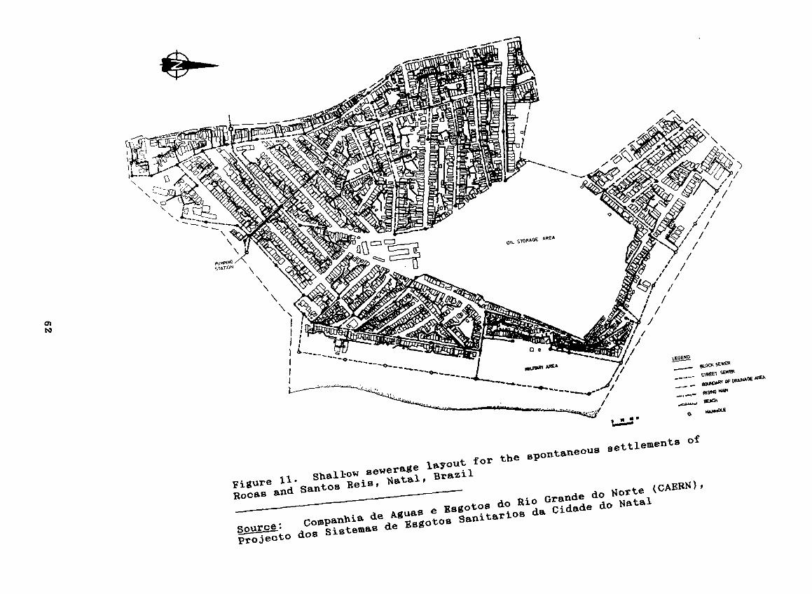
forpjgure 11. Shal1~°”8~~erftge
ReiS,Rocas and SantOS
LEGEN°etfl SE~
- si~1 SEWS~
—
:—- ~—~
~~ggot00 do Rio Grande do ~ (CAERN)’compahh1~ta de~ ~5got0ø SanitattOB da Cidade do Hataldos
Ptoie0tO
\
0)
/
0
QL STORA~âREA
//
//
//
/
//
thesettlem~~t8 of

found that shallow sewers were oheaper than even on—site sanitationsystems at densities In exoess of 160 persons per heotare (see figure5. . Changes in oonventional approaohes in exeouting the system toaooommodate oommunity partioipatlon In planning and maintenanoe work,and in adjusting tariffs to take aooount of the low investment oosts,were suooessfulby introduoed by CAERN. The Sanitatlon Research Unitestablished by CAERN developed the methodology used and justifled theohanges In tarlff struoture introduoed for the new system.Evaluations of the system undertaken at frequent intervals durlng thepast five years have deteoted a gradual prooess of upgradlng ofpbumbing instablations through the provislon of kitohen slnks, laundrysinks, showers eto. No problems have been observed, and informationtransferred durlng oonstruotlon to the oommunity in rebation tomaintaining the blook sewers has proved adequate to ensure a highlevel of self—help maintenanoe. Blookages in blook sewers have provedto be rare and, whenever these have ooourred, they have beeneffeotively removed by members of the oommunlty themselves.
Within fIve years, the shallow sewer system had spread to varloustowns within Rio Grande do Norte and was being implemented in all low-Inoome houslng sohemes in Rio Grande do Norte without exoeption.During this period, It also spread to other states suoh as Pernambuoo,Rio de Janeiro, Minas Gerais and Sergipe. 47/48/ The oonoept of aoommon house oonneotion through the use of shallow blook sewers is nowbeing extended to the supply of water in order that the same basiounit of sooial mobilization - the blook - oan be used to supply waterthrough a single meter for subsequent assessment of water and sewagetariffs amongst the householders oonneoted to a oommon water meter andsewage house oonneotion. Supplylng, maintaining and reading watermeters have been problem in developIng oountries, and the reduoednumber of meters aohleved by adoptlng blook meters, as opposed toindlvidual household meters, oreates oonsiderable savlngs.
B. Planned low—ineome housing sehemes in theState of RIo Grande do Norte, Brazil.~/,~/,fl/,4i/,i~/ ,4i/,i~/,4~/
Conoomitant with the development of the shallow sewer system inthe unplanned, spontaneous squatter settlements of Rooas and SantosReis in 1981, the oonoept was also extended to a low—inoome houslngsoheme In Santa Cruz, a oIty in the interior of the State of RIoGrande do Norte.6/ Eight hundred low-oost houses were built with anaverage gross population density of 110 persons per heotare, thehouses intended for one of the poorest groups In Santa Cruz’soommunlty who had been made homeless during a flood earlier In theyear. The houses were oonstruoted to standard designs and wereprovlded with in—house water oonneotlons and a pour—flush oeramlotoilet bowl, a bathing area, and kltohen and olothes washing sinks.The kitohen and olothes—washing sinks were oonneoted to a grit/greasetrap and disoharged to shallow sewers. Shallow sewers were laldthrough the baok gardens and oonneoted to a sparsely distributedstreet—oolleotor sewer network whloh was lald in sidewaiks to enableit to maintain its shallow depth. The topography of the projeot areawas suoh that It oovered parts of three separate drainage basins, andthe sewage drained from eaoh basin was oonneoted to a differenttreatment works, oonsisting of a oomblnation of anaerobio andfaoultative pond, a oommunal septio tank and a faoultative pond, andalso direot disoharge to a faoultative pond. The treated effluentswere used for irrigating fodder crops.
63
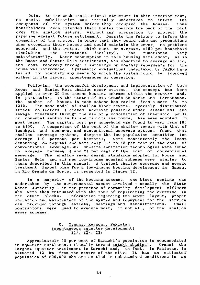
Owing to the weak institutlonal struoture in this interior town,no sooiab mobilization was initially undertaken to inform theoooupants of the system before they oooupied the houses. Somehouseholders even extended thelr houses towards the baok of the plotover the shalbow sewers, without any preoaution to proteot thepipeline agalnst future settlement. Despite the failure to inform theoommunlty of the system, in order that they could take due preoautlonswhen extending their houses and could malntain the sewer, no problemsooourred, and the system, whioh oost, on average, $150 per househobd(Inoludlng the treatment facility), has funotloned verysatisfactorily. Water oonsumptlon In this housing settlement, as Inthe Rooas and Santos Reis settlements, was observed to average 45 lod,and oost reoovery through a suroharge on monthly repayments for thehouse was introduoed. Systematio evaluatlons undertaken by CAERN havefaibed to identify any means by which the system oould be Improvedeither in Its bayout, appurtenanoes or operation.
Following the suooessful development and Implementation of bothRooas and Santos Reis shallow sewer systems, the oonoept has beenapplied to over 20 low—inoome housing sohemes wlthin the country and,in partioubar, in the states of Rio Grande do Norte and Pernambuoo.The number of houses in eaoh soheme has varIed from a mere 56 to1312. The same model of shallow block sewers, sparsely distributedstreet oolleotors (looated wherever possible under sidewaiks) andsewage treatment through the use of a oombination of anaeroblo pondsor oommunal septio tanks and faoultative ponds, has been adopted inmost oases. The oapital oost per household was found to vary from $85to $150. A oomparison of the oost of the shallow sewers wlth that ofbeaohpit and soakaway and oonventional sewerage options found thatshallow sewerage systems, despite the low population densities (onaverage 110 persons per heotare), were oonsistently the leastdemanding on oapltal and were only 9.5 to 15 per oent of the oost ofoonventional sewerage.38/ On-site sanitation teohnologies were foundto average between 14 and 21 per cent of the oost of oonventionalsewerage. The shallow sewer design standards adopted for Rooas andSantos Reis and all new bow—inoome housing sohemes were similar tothose desoribed in this manual. A typioal shalbow sewerage and sewagetreatment bayout plan for a bow—income housing development in Maoau,in Rio Grande do Norte, is presented in figure 12.
In a majority of the housing sohemes, one bbook meeting wasundertaken by the governmental agenoy Involved - usually the StateWater Authority - In the presenoe of oommunity devebopment offioerswho were then entrusted with the task of replioating the exerolse inthe other blooks. Information regarding the sewer layout, properoperation and maintenanoe of the system and repayment for the servicewas provided through beafbets, meetings and demonstrations. Smalloontraotors were used to exeoute most, 1f not all, of the shalbowsewer sohemes.
C. Orangl, Karaohi, Pakistan(spontaneous sguatter devebopment)
fl/, &?./~~Ji/
Approxlmately 40 per oent of Karachi’s populatlon Is aooommodatedin squatter settlements (looally termed katohi abadies). Orangi, thelargest squatter settlement in Karachi and, in faot, in Pakistan, issltuated 12 km from the oentre of the oity. It has an estimatedpopulatlon of 800,000 who are settled in substandard oonditlons in an
64
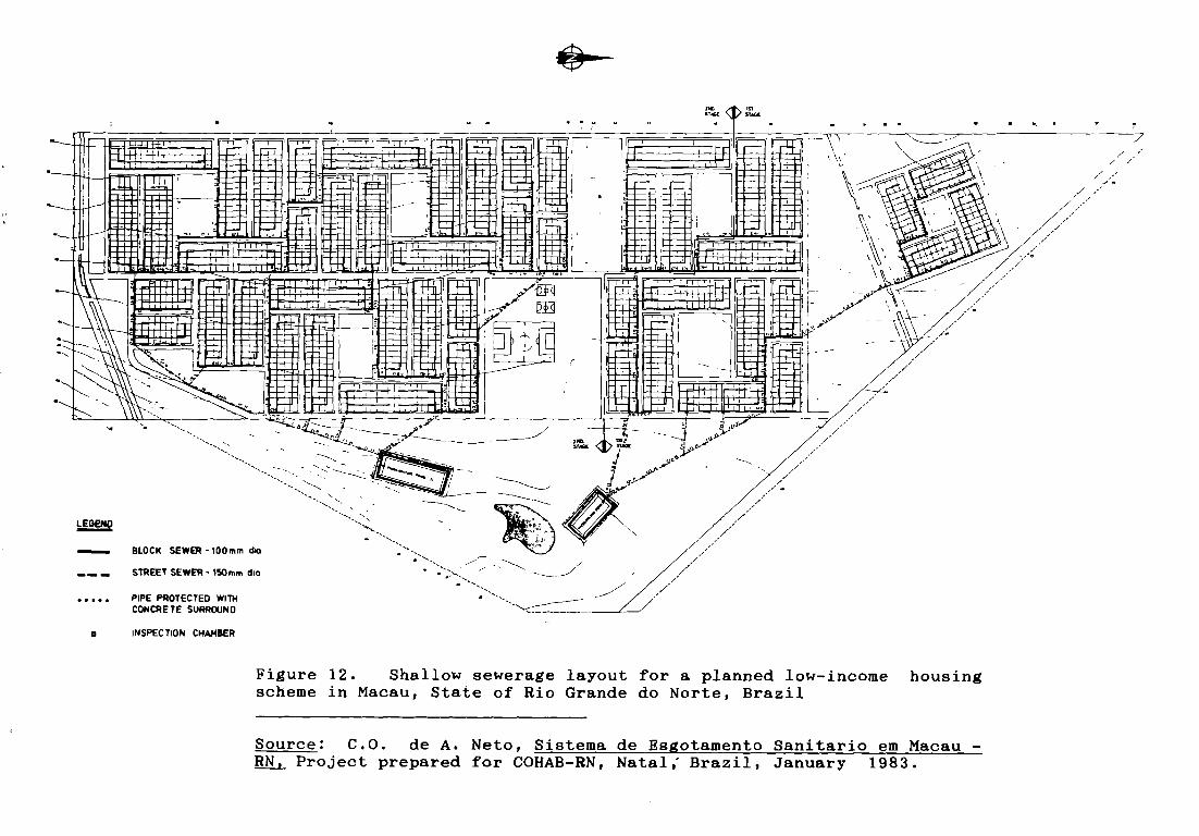
_____ J -~ ~r ~
_ _
Figure 12. Shallow sewerage layout for a planned low-income housingscheme in Macau, State of Rio Grande do Norte, Brazil
Source: C.O. de A. Neto, Sistema de Esgotamento Sanitario em Macau —
B±L Project prepared for COHAB-RN, Natal; Brazil, January 1983.
t 1S
.~
—7//
/ /
/ /
~ 4~~- ~—~-~—----— ~ ~J- - :~--.-~,~ 5TA~
-- ~- - 1-- / --
— —“ / II ~- ~-- t —~--—--
~fOENQ
BLOCK SEW~-100 mm dia
—— — STREET SEWER - 150 mm dia
PIPE PROTECTED WITHC0N~RETESURROUND
0 INSPECTION CHAI4BER

area oovering approximateby 2000 heotares. Average househobd inoomeswere at subsistenoe levebs, and Infa~t mortallty and the inoidenoe ofexoreta—related infeotions were both high.
The settlement resulted from the migration from the former EastPakistan whioh ocoured during the period immediately before and afterthe oreation of Bangladesh. Abthough the largest of the katohiabadies, Orangi laoked the minimum of basio infrastruoture andessential amenitles. In Maroh 1983, the Bank of Credit and CommeroeInternational Foundation, in oollaboration with UNCHS (Habitat),initiated a three-year oommunity devebopment projeot, aimed atamebIorating the living oonditions of the people of Orangi.
One of the aotlvities of the project was the promotion andimpbementatIon of low—oost Infrastruoture interventions, amongst whiohsanitation was given high priority, owing to the urgent need for It inthe projeot area. The bulk water supply to Orangl was throughunevenly distrlbuted oommunab standpoats whioh operated four hours aday in the afternoon. Water was stored in oompound tanks in amajority of the houses, and, on average, 20 to 30 bitres were used byeaoh household member eaoh day. Only rudimentary plumbing fixtureswere present In the area, and most washing was oonfined to a specialwet room used for both bathing and washing obothes and utensils.Buoket latrines were predominantly used in the area, together withvault toilets. Exoept in the oase of buoket latrines, standardoistern—flush oeramic and mosaio squat pans, operated in the manualpour—fbush mode, were the norm. The sooio—religious oustom of usingwater for anab oleansing necessitated the carrying of water to thetoilet. Soavengers, who undertook the removal of exoreta from thebuoket latrines, oharged $1.00 per month for thç service, but noprovision existed for the disposal of sullage.
In 1984, Chisty Nagar, a Bihar cominunity within Orangi, wasidentified to initiate the sanitation programme. The projeot areaoontained 555 plots, of whioh 408 had houses built on them, and had anaverage gross population density of 193 persons/heotare. A remarkablefeature of the area was its regular urbanization, wlth average plotsizes of 100 ritZ of which, on average, 50 per cent was oonstruotedarea. Even more remarkable was the existence of a service bane,designed to provide aooess to soavengers for removing nightsoil fromthe houses.
General oommunlty meetings were held after mldday prayers at themosque on Frldays. Local oommunity leaders were identified, and theprogramme was desoribed. Disoussions held with the oommunity revealeda preference for some form of waterborne sanitation, but oonventionalwisdom diotated that the unrebiable intermittent water supply and thebow bevels of water oonsumption in the area would rule out the use ofany form of waterborne sanitation system (average oonsumption wasmeasured to be 27 bod).
Onby shalbow sewers, beoause of their mode of operation, offeredany chance of success. Although shallow sewers had not beenpreviously installed under similar oonditions of bimited water use andmanuably flushed oeramic toilet squat~pans, their mode of operationsuggested that, even under such conditions, they should funotionsatisfaotorily. An analysis of the oost of various sanitatlonoptIons also indicated shallow sewers to be one of the oheapestoptlons. It was, therefore, decided that it should be implemented inChisty Nagar.
66

Meetings were held with the community to present the designs andestablish a procedure for raising the required capital whioh had to beraised in full by the communlty. A trusted member of the communitywas nominated by It to be the custodian of all funds ralsed. It wasalso envisaged that maintenance committees~i4ould be establIshed associal mobilization advanced, in order to maintaln the completedsewerage system.
Shallow sewers, laid in the service lanes (until then only usedby soavengers for emptyIng nightsoil buckets), were designed accordingto criteria similar to those deveboped in Brazil, and they receivedthe wastewater from manually flushed squat pans and all householdsullage. A grit/grease trap, made of cement mortar Including flneaggregates was provided in each house, to act as a focus for sullageoollection and, also, serve as a preventive maintenance devioe. Oneinspection ohamber was provided to serve two plots, and each watercboset connection was appropriately ventllated. Besides the servicelane sewers, an interoeptor channel was provided to drain the lanesewers to a common communal septic tank, and the effluent from thetank was discharged to the nearby dry water course. The shallow sewerbayout adopted in Chisty Nagar is shown in figure 13.
The internal plumbing and lane sewers comprised 30 and 31 percent respeotively of the total oost, which amounted to approximately$45 per plot. Beoause only 408 of the 555 plots had houses on them,the oost per household was just over $61. A twin pit pour-flushtoilet, which diposes of exoreta only, oost approximately $51. Theprojeot endeavoured to reduce oosts through local manufacture ofspecifio oomponents, suoh as the grit/grease trap and pipes. The oostof inspeotion ohambers was also reduced by using bocabby availablestone ihstead of brioks or cement blooks.
Despite the bow fbows, the system has functioned perfeotly wellfor over a year: no blookages have occurred, showing that properlydesigned and constructed sewers do not require large quantities ofwater for troubbe-free operation. This first attempt by an NGO tointroduce shallow sewers to low—income settlements was, however, notwithout problems. A recent evaluation of the Chisty Nagar sanitatlonprogramme has attempted to identify some of these problems. fl/
The prinoipal objeotive of community motivation was to generate afinancial contrlbution to the soheme. Little effort was devoted tooreating a oommunity organization oapable of taklng on otherdevelopment projects on oompletion of construction and alsomaintaining the newly Introduced system. Efforts to raise the entIreoapItal oost prior to construotion proved somewhat difficult, not gomuoh as a resubt of financial bimitations but rather as a result ofweak oommunity organization.
A oontractor approach to the provision of sanitation rather thana oommunity development kpproach, an initial construction failure whenattempting to construct a septic tank in a service lane and theinablbity of the project to stick to a single price withoutintroducing additions at a later stage raised doubts. Technically,however, the evaluation proved extremely positive, except for notingsome build-up in the sewers of sand that Is thought to have enteredthe system at the inspection chambers during the execution of thehouse oonnections and, perhaps, during the oonstruotion of the sewersthemselves. Some spillover from the grit/grease trap may also havebeen responsible, although this could be eliminated by informinghouseholders of the need to clean out the trap frequently.
67
H
0,L~GEND
o Channel Inspection Chamber
6 Dia R C C Pipe
Concrete Protection
• lnspection Chamber
/~~~
Figure 13. Shallow sewerage layout for the spontaneous settiement ofChisty Nagar, Orangi, Karachi, Pakistan.
Source: J. Shah, and A.Q. Alvi, Technical Report, BCCI CommunityDevelopment Project, Orangi, Pakistan, report of the United NationsCentre for Human Settlements (Habitat), Nairobi, August 1985

One of the chief constraints to expanding tl%e scheme to otherareas at a very fast pace is the need to raise the total capital costprior to construction. This impediment is best removed by creating arevolving fund and a suitably efficient institution to apply andrecover funds for the provisionof shallow sewerage schemes. AsKarachi launches its ambitious programme to develop the katchiabadies, it is expected that the technology introduced through thepresent programme will serve as a model for adoption in other low—income areas.
69

NOTES
1. Official Records of the General Assembly, fortieth session,Progresa in the attainment of the goals of the InternationalDrinking Water Suppiy and Sanitation Decade, Report of theSecretary-General (A/40/108) (New York, 1985.)
2. World Housing Survey, 1974 (United Nations Publication, Sales No.E 75.IV.8) table 48.
3. Kalbermatten, J.M., and others, Appropriate SanitationAlternatives - A Technical and Economie Appraisai (Baitimore,Johns Hopkins University Preas, 1982).
4. lcd - litres per capita per day.
5. Otis, R.J., and Mara, D.D., The Design of Small Bore SewerSystems, TAG Technical Note No. 14) (Washington, D.C. 1985).
6. Melo, J.C., Sistema Alternativo de Esgotamento Sanitario da SantaCruz (Conunto Conego Monte, project prepared for Companhia deHabitacao Popular do Rio Do Norte (COHAB - RN), Natal, Brazil,August 1981.
7. These inciude annuitized investment costs and all operation andmaintenance costs, inciuding the cost of the water used forflushing the toilet.
8. Swaffield, J,A., Demonstration Projects in Low-cost Water Suppiyand Sanitation, Report on Mission to Brazil (World BankTechnology Advisory Group, Washington, D.C., 1981.
9. Swaffield, 3.A., and Wakelin, R.H.M., Evaluation of the SolidTransport Performance of the SIBR/IFO Pour-flush Sguat PlateDesign (Brunel Industrial Services Bureau, Brunei University,England, 1983).
10. Swaffield, J.A., “A study of the effect of water conservation onW.C. discharge and drainage system transport efficiency,” ThePublic Health Engineer, vol. 8 (1980), No. 3 pp. 126—130.
11. Wakelin, R.H.M., “The effects of W.C. discharge geometry on thetransport of solids in internai drainage systems”,The PublicHealth Eng~neer, vol.7 (1979), NO.4. pp. 170—175.
12. Liilywhite, M.S.T., and Webster, C.J.D., “Investigations of drainblockage and their implications on design”,The Public HealthEngineer, vol.7 (1979), No. 4, pp. 170-175).
13. British Standards Institution (BSI), Sanitation Pipework AboveGroundL Code of Practice CP304 (London, 1968), pp. 14-22.
14. Kaibermatten, J.M., and others, Appropriate SanitationAlternatives - A Planning and Design Manual (Baltimore, JohnsHopkins University Press, 1982).
15. Swaffield, J.A. and Wakelin, R.H.M. “Observation and analysis ofthe parameters affecting the transport of waste. soiids ininternal drainage systems”, “The Public Heaith Engineer, voi.4(1976), No.6, pp. 165—170.
70

16. Assooiaoao Brasileira de Normas Teonicas (ABNT) Elaboracao deProjectos de Redes de Esgotos Sanitarios, (PNB-567) (Rio deJaneiro 1975).
17. Vickers, J.A., Francis, J.R.D. and Grant, A.W., Erosion of Sewersand Drains, Research Report No. 14 (London Construction IndustryResearch and Information Association).
18. British Standards Institution (1351), Building Drainage, Codeof Praotice CP3O1 (London, 1971), pp. 30-41.
19. Rosrud, T., “User requirement regarding draining pipework,”Proceedings of CIB W62 Symposium (Oslo, 1977).
20. Texas Water and Sewage Works Assoolation, Manual for Sewage PlantOperators, (Austin, 1955).
21. McGarry, M.G., Evaluation of the CDP Low-cost Sewerage Prq,~ectChisty Nagar, Pakistan, report to the United Nations Centre forHuman Settlements (Habitat), Nairobi, September 1985.
22. Sinnatamby, G.S., Teohnical Report: BCCI—Community DevelopmentProject, Orangi~ Pakistan, report of the United Nations Centrefor Human Settlements (Habitat), Nairobi, April 1984.
23. Shah, J., and Alvi, A.Q., Technical Report: BCCI-CommunityDevelopment Project, Orangl, Pakistan, report of the UnitedNations Centre for Human Settlements (Habitat), Nairobi, August1985.
24. InstItute of Plumbing, Data Book (Hornchuroh, England, 1973).
25. Nash, R.W., and Panter, A.E., “To sewer or not to sewer: theWater Act 1973, sections 14-16: the problems of the privatedeveloper” The Public Health Engineer, vob.7, No. 3, pp. 113-120.
26. Sinnatamby, G.S. , “Low—cost sanitation systems for urbanperipheral areas in northeast Brazil”, Ph.D. thesis, Departmentof Civil Engineering, University of Leeds, Leeds, England, August1983.
27. American Society of Civil Engineering, Gravity Sanitary sewerDesign and Construotion, (New York, 1982).
28. Macedo, E.S., “Caloubo do esooamento na rede de esgotossanitarios do sistema separador absoluto” paper presented at1 Congresso Brasileiro de Engenharia Sanitarla, Rio de Janeiro,July 1960.
29. Mara, D.D., “Macedo’s modifioation of Manning’s equation”, ThePublic Health Engineer, vol. 13, No. 4 (Oçtober, 1985, p. 124.
30. Hydraulic Research Station, Tables for the Hydraulic Design ofPipes, (London, Her Majesty’s Stationery Offioe, 1977).
31. Bland, C.E.G., Design Tables for Determining the FlowCapacityofVitrified Clay Pipellnes (London, Clay Pipe DevelopmentAssociation Limited, 1975).
32. Ifo Sanitar, Ifo Cascade - The Water Saver: 0.8 and 1.6 gal
.
Water Closets (Bromolla, Sweden, Ifo Sanitar AB, 1984).
71

33. Communioation with Technology Advisory Group, Brazil, 1985~
34. Ifo Sanitar, Low Volume Water Closet System - Sguatting Type,World Bank, development project, a summary, (Bromolla, IfoSanitar AB, 1984).
35. Bland, C.E.G., “Loads on burried rigid pipes: recent research”,The Public Health Engineer, vol.9 (1981), 3, pp. 159-166.
36. Simpson-Hebert, M., Methods for Gathering Socio—oulturab Data forWater Supply and Sanitation Projects, TAG Teohnical Note No. 1(Washington D.C., World Bank 1983).
37. Parlato, R., A Monitoring and Evaluation Manual for Low—costSanitation Programmeg in India, TAG Technical Note No. 12(Washington D.C., World Bank 1984).
38. Cavalcanti, J.C., “Redes simplicadas de esgotos sanitarios,”paper presented to the seminar on “Technologias Baixo Custo paraSaneamento Baslco Liineira, Sao Paulo, August 1984.
39. Compahnia de Aquas e Esogotos do Rio Grande do Norte (CAERN),Vilas de COHAB - Ponta de Lanca de Soluooes Raclonales, l2thBrazilian SanItary and Environmental Congress, Camborlu, SantaCatarina, 1983.
40. tlinisterio do Desenvolvimertto Urbana e do Meio-Ambiente, Manualde Saneamento: Reses de Eggotos Simplifioadas (RES) prepared bythe Council for National and Urban Development under the UNDP-funded programme INT/81/047 executed by the World Bank, Brasilia,1986.
41. Sinnatamby, G.S. Projeotos de Tratamento dos Esgotos: ConjuntoHabitacional Conego Monte - Santa Cruz, project prepared forCOHAB-RN, Natal, Brazil, February 1981.
42. Companhia de Aquas e Esgotos do Rio Grande, do Norte (CAERN).Projecto dos Sistemas de Esgotos Sanitarios da Cidade do Natal
,
Bacia 01 - Rocas e Santos Reis (Natal, 1982).
43. Neto, C.O. de A., Sistema De Esgotamento Sanitario em Macau - RNproject prepared for COHAB-RN, Natal, January 1983.
44. Sinnatamby, G.S. Sistema De Esgotamento Sanitario do ConjuntoHabitacional da COHAB em Alexandria-RN, Primeira Etapa, projectprepared for COHAB-RN, Natal, October 1982.
45. Companhia de Aquas e Esgotos do Rio Grande do Norte (CAERN),Sistema de Esgotamento Sanitario do Conjunto Habitacional DaCOHAB em Currais Novas - RN, Primeira Etapa (Natal, 1982).
46. Neto, C.O. de A., Sistema De Esgotamento Sanitario Do ConjuntoHabitacional Da COHABem Currais Novas-RN, Segunda Etapa, projectprepared for COHAB-RN, Natal, October 1982.
47. Neto, C.O. de A, “Uma solucao efficaz e de baixo custo para oesgotamento sanitario urbano, Engenharia - Sanitaria (Rio deJaneiro), vol. 24, No.2 (April/June 1985), pp. 237—238.
48. Mebo, J.C.R., “Sistemas condominiais de esgostos,” EngenhariaSanitaria, vol. 24, No. 2, pp. 237—238.
72

Annex 1
SHALLOWSEWERDESIGN EXAMPLE
A shallow sewer scheme is proposed for the new low—income housingscheme illustrated in figure 1. Each house is to be provided with apour-flush ceramic toilet bowi and a single tap located withmn thehouse in a room designated for washing clotbes and utensils and forbathing. A grit/grease trap is provided in this Wet room. Becausethe population of the settiement has already reached saturation, noprovision is required for future development, although thehouseholders are expected to upgrade their plumbing fixtures to have,in the future, a multiple-tap, in-house, water-supply service, withwash basins, kitchen sinks, showers etc. Water consumption is,therefore, expected to rise from the current 50 lcd to an estimatedfinal value of 120 lcd. Being located in a semi-and region, nosignificant infiltration to the sewer is expected, and any smallinfiltration will be controlled through good construction. Thefollowing design criteria are assumed:
Flow estimation
Maximum water consumption, q 120 lcd
Coefficient of peak daily flow variation, ki = 1.2
Coefficient of peak hour flow variation, k2 2.0
Ratio of sewage generated to water consumed, C 0.8
Average number of persons per house 5
Number of houses served N
Flow in sewers = 0.8 x 1.2 x 2.0 x P x 120 + 0 + Q286400
= 0.002667P + Q2
= 0.0133N + Q2 1/sec
Minimum peak flow in any block or street sewer z 2.2 1/sec.
Minimum and maximum depth of flow at peak flow
Minimum depth of flow 0.2 x pipe diameter
Maximum depth of flow 0.8 x pipe diameter
Minimum gradient
Minimum gradient to achieve a self—cleansing velocity of
0.5 m/sec at minimum depth of flow 0.006 (1 in 167)
Minimum pipe diameters
Block sewers lOOmm
Street sewers l5Omm
73
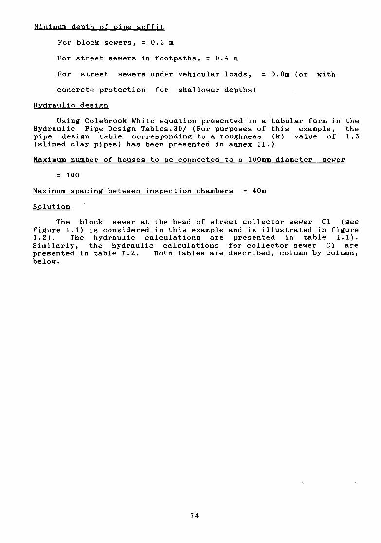
Minimum depth of pipe soffit
For block sewers, = 0.3 m
For street sewers in footpaths, = 0.4 in
For street sewers under vehicular loads, 0.8m (or with
concrete protection for shallower depths)
Hjrdraulic design
Using Colebrook-White equation presented in a tabular form in theHydraulic Pipe Design Tables.30/ (For purposes of this example, thepipe design table corresponding to a roughness (k) value of 1.5(slimed day pipes) has been presented in annex II.)
Maximum number of houses to be corinected to a lOOmm diameter sewer
= 100
Maximum spacing between inspection chambers = 40m
Solution
The block sewer at the head of street collector sewer Cl (seefigure 1.1) is considered in this example and is illustrated in figure1.2). The hydraulic calculations are presented in table 1.1).Similarly, the hydraulic calculations for collector sewer Cl arepresented in table 1.2. Both tables are described, column by column,below.
74
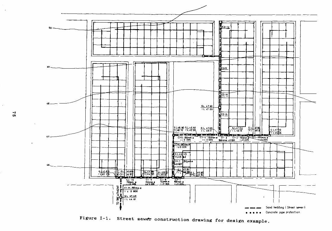
c,1
— _ _ Sond bedding ( Street sewer). . . . . Concrete pipe protect on
Figure 1-1. Street sew~r construetjon drawing for design example.
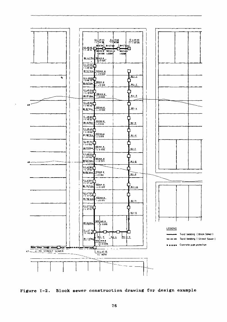
47
LEGEND
Sard beddirig Block Se~ert
— — Send bedding t Street Sewer)
• • •~. Concrete pipe potection
Figure 1—2. Block sewer construction drawing for design example
76
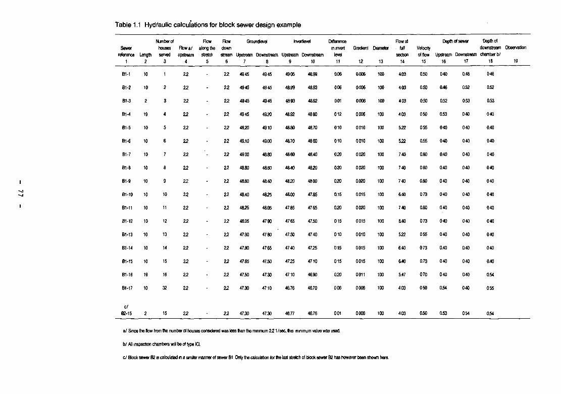
Table 1.1 Hydtaulic caicui~tionsfor block sewer design example
-4—t
a/ Since die Aow kom die number ofhousea conasderad was lees ten die minimum 221/sao, die minimum value was used
bi Alt inspecton ctianibers wil be of t)pe ta
Sewarraleraice
1Lengdi
2
Nomber ofhousesserved
3
Aowalupsfream
4
FtowSong diesfretcl,
S
Aowdown
stream6
Grotmdtevel
tipstream Downstream7 8
hiverdeM
Upsfream 0owr~eani9 10
Otiferencein inveil
teriet11
Gradient
12
Diajnedir
13
Aow al. fullseofion
14
Velocityof t bie
15
Depdi
U~reani16
om
Dowristreazfl17
Depib ofdownstrea,nchamber bi
18
Observatlon
19
B1-1 10 1 2.2 - 22 4945 4945 4905 48.99 0.06 0006 100 4.03 050 040 0.46 046
81-2 10 2 22 - 22 4945 4945 48.99 48.93 006 0006 100 403 050 0.46 0.52 0.52
81-3 2 3 22 - 22 4945 4945 4893 48.92 001 0006 100 403 050 052 0.53 0.53
B1-4 19 4 22 - 22 4945 49.20 48.92 4880 012 0006 100 400 050 053 040 040
81-S 10 5 22 - 22 4920 4910 48.80 48.70 010 0010 100 5.22 055 040 040 0.40
B1-6 10 6 22 - 22 49.10 49.00 48.70 4860 010 0010 100 5.22 0.55 040 040 040
81-7 10 7 22-
22 4900 48.80 4860 48.40 020 0020 100 740 0.80 0.40 040 040
81-8 10 8 22 - 22 48.80 49.60 48.40 4820 020 0020 100 740 080 0.40 040 040
81-9 10 9 22 - 22 48.60 48.40 48.20 4800 020 0.020 100 740 0.80 040 040 040
81-10 10 10 22 - 22 48.40 48.25 48.00 47.85 0.15 0015 100 140 073 040 040 040
81-11 10 11 22 - 22 4825 48.05 47.85 4765 020 0020 100 740 0.80 040 040 040
81-12 10 12 22 - 22 48.06 4790 4765 4750 015 0015 100 140 073 040 040 040
81-13 10 13 22 - 22 47.90 4780 47.50 4740 010 0010 100 5.22 055 040 040 040
81-14 10 14 22 - 22 47.80 4765 4740 4725 015 0015 100 8.40 073 0.40 0.40 040
81-15 10 15 22 - 22 47.65 47.50 4725 4710 015 0015 100 140 0.73 040 040 0.40
81-16 19 16 22 - 22 47.50 47.30 4710 48.90 020 0011 100 £47 070 040 0,40 054
81-17 10 32 22 - 22 47.30 4710 48.76 48.70 006 0006 100 403 050 0.54 040 055
c/82-15 2 15 22 - 22 47.30 4720 48.77 4176 001 0006 100 403 050 0.53 054 0.54
cl Rock sewer 82e calculaad na simlar manner ofsewer 81 Ontydie calcutaton fordie S stra~iof block sewer 82 bas flowever been shown twa.

Table 1.2 Hydraulic calculations for collector street sewer design example
—4
s/er 64fiousas)x1X01333+a4=4251/sac.
Sewarraference
1langdi
2
Numbar offiousasserved
3
How a/upstream
4
Aowslong die
alretcli5
Flowdoen
stream6
Groundleris
Upstresm Downslream7 8
lrrsdavel
Upalresm Downslream9 10
Dilferencein meert
level11
Grediant
12
Diarnatar
13
How alfull
secbon14
Valoodyofdow
15
Dapdi
Upslrasm16
of aan
Downslream17
‘ Dapdi ofdownslreamcliamber b/
18
Obsa,vsl,on
19
01-1 30 32 220 - 220 4710 47.00 4655 46.37 018 0006 150 1196 050 055 063 063
C1-2 30 32 220 - 220 4700 4700 46.37 46.19 018 0006 150 1196 050 063 0.81 0.81
01-3 14 32 220 - 220 4700 4700 4619 4611 008 0006 150 1196 050 021 029 089
01-4 34 319 220 2.40 425 4700 46.90 4611 45.91 020 0006 150 11.96 062 0.89 0.99 0.99
01-5 34 319 425 - 425 4190 4190 45.91 45.71 020 00% 150 1196 062 099 119 119
01-6 31 319 425 - 425 46.90 4140 4571 45.52 019 00% 150 11.96 062 .119 0.88. 0.88
01-7 31 319 425 - 425 4140 45.85 45.52 4530 027 0007 150 12.92 0.66 028 0.55 058
01-8 25 337 425 024 449 45.85 4580 4527 45.12 015 0006 150 11.96 062 058 068 068
C1-9 25 337 449 - 449 4580 4520 4512 44.97 015 01106 150 11.96 062 0.88 0.83 0.83
01-10 29 369 449 043 492 4520 45.80 44.97 44.80 017 0006 150 1126 065 023 100 1.00
01-11 32 401 492 043 525 45.80 45.40 4420 44.61 019 0006 150 1196 066 1.00 079 079
b/C2-15 40 255 2.40 - 2.40 4760 4700 4705 46.45 0.60 0015 150 1896 0.80 055 055 0.89
03-1 14 18 220 - 220 45.90 45.85 45.35 4527 006 0006 150 1196 050 055 058 058
04-1 7 32 220 - 220 4520 4580 4525 4521 004 0006 150 11.96 050 0.55 0.59 150
82-15
bi Cslculaled as in collectorsewer Cl, Only dia calculafion fordie last stretcli of collector san 02 bas however been shown hate.
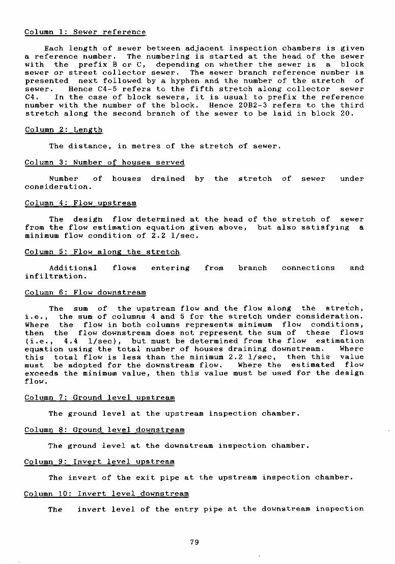
Column 1: Sewer reference
Each length of sewer between adjacent inspection chambers is givena reference number. The numbering is started at the head of the sewerwith the prefix 8 or C, depending on whether the sewer is a blocksewer or street collector sewer. The sewer branch reference number ispresented next followed by & hyphen and the number of the stretch ofsewer. Hence C4-5 refers to the fifth stretch along collector sewerC4. In the case of block sewers, it is usual to prefix the referencenumber with the number of the block. ilence 2082-3 refers to the thirdstretch along the second branch of the sewer to be laid in block 20.
Column 2: Length
The distance, in metres of the stretch of sewer.
Column 3: Number of houses served
Number of houses drained by the stretch of sewer underconsideration.
Column 4: Flow upstream
The design flow determined at the head of the stretch of sewerfrom the flow estimation equation given above, but also satisfying aminimum flow condition of 2.2 1/sec.
Column 5: Flow alon,g the stretch
Additional flows entering from branch connections and
infi1tr~tjon.
Column 6: Flow downstream
The sum of the upstream flow and the flow along the stretch,i.e., the sum of columns 4 and 5 for the stretch under consideration.Where the flow in both columns represents minimum flow conditions,then the flow downstream does not represent the sum of these flows(i.e., 4.4 l/sec), but must be determined from the flow estimationequation using the total number of houses draining downstream. Wherethis total flow is less than the minimum 2.2 l/sec, then this valuemust be adopted for the downstream flow. Where the estimated flowexceeds the minimum value, then this value must be used for the designflow.
Column 7: Ground level upstream
The ground level at the upstream inspection chamber.
Column 8: Ground level downstream
The ground level at the downstream inspection chamber.
Column 9: Invert level upstream
The invert of the exit pipe at the upstream inspection chamber.
Column 10: Invert level downstream
The invert level of the entry pipe at the downstream inspection
79
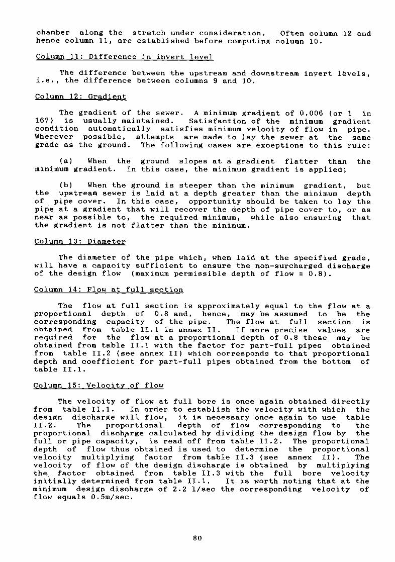
chamber along the stretch under consideration. Often column 12 and
hence column 11, are established before computing column 10.
Column 11: Difference in invert level
The difference between the upstream and downstream inyert lëvels,
i.e., the difference between columns 9 and 10.
Column 12: Gradient
The gradient of the sewer. A minimum gradient of 0.006 (or 1 in167) is usually maintained. Satisfaction of the minimum gradientcondition automatically satisfies minimum velocity of flow in pipe.Wherever possible, attempts are made to lay the sewer at the samegrade as the ground. The fotlowing cases are exceptions to this rule:
(a) When the ground slopes at a gradient flatter than theminimum gradient. In this case, the minimum gradient is applied;
(b) When the ground is steeper than the minimum gradient, butthe upstream sewer is laid at a depth greater than the minimum depthof pipe cover. In this case, opportunity should be taken to lay thepipe at a gradient that will recover the depth of pipe cover to, or asnear as possible to, the required minimum, while also ensuring thatthe gradient is not flatter than the minimum.
Column 13: Diameter
The diameter of the pipe which, when laid at the specified grade,will have a capacity sufficient to ensure the non—surcharged dischargeof the design flow (maximum permissible depth of flow 0.8).
Column 14: Flow at full section
The flow at full section is approximately equal to the flow at aproportional depth of 0.8 and, hence, may be assumed to be thecorresponding capacity of the pipe. The flow at full section isobtained from table 11.1 in annex II. 1f more preejse values arerequired for the flow at a proportional depth of 0.8 these may beobtained from table 11.1 with the factor for part-full pipes obtainedfrom table 11.2 (see annex II) which corresponds to that proportionaldepth and coefficient for part-full pipes obtained from the bottom oftable 11.1.
Column 15: Velocity of flow
The velocity of flow at full bore is once again obtained directlyfrom table 11.1. In order to establish the velocity with which thedesign discharge will flow, it is necessary once again to use table11.2. The proportional depth of flow corresponding to theproportional disch~rge calculated by dividing the design flow by thefull or pipe capacity, is read off from table 11.2. The proportionaldepth of flow thus obtained is used to determine the proportionalvelocity multiplying factor from table 11.3 (see annex II). Thevelocity of flow of the design discharge is obtained by multiplyingthe~, factor obtained from table 11.3 with the full bore velocityinitially determined from table 11.1. It is worth noting that at theminimum design discharge of 2.2 1/sec the corresponding velocity offlow equals 0.5m/sec.
80
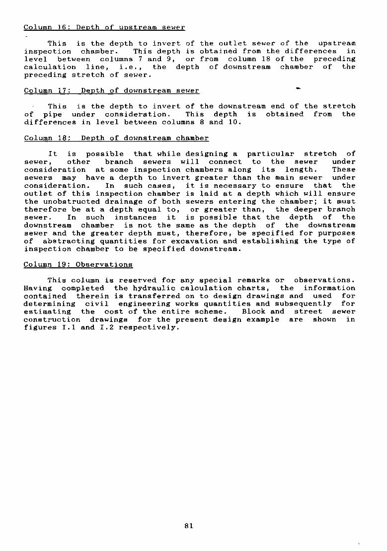
Column 16: Depth of upstream sewer
This is the depth to invert of the outlet sewer of the upstreaminspeetion chamber. This depth is obtained from the differences inlevel between columns 7 and 9, or from column 18 of the precedingcalculation line, i.e., the depth of downstream chamber of thepreceding stretch of sewer.
Column 17: Depth of downstream sewer
This is the depth to invert of the downstream end of the stretchof pipe under consideration. This depth is obtained from thedifferences in level between columns 8 and 10.
Column 18; Depth of downstream chamber
It is possible that while designing a particular stretch ofsewer, other branch sewers will conneet to the sewer undereonsideration at some inspection chambers along its length. Thesesewers may have a depth to invert greater than the main sewer underconsideration. In such cases, it is necessary to ensure that theoutlet of this inspection chamber is laid at a depth whieh will ensurethe unobstructed drainage of both sewers entering the chamber; it musttherefore be at a depth equal to, or greater than, the deeper branchsewer. In such instances it is possible that the depth of thedownstream chamber is not the same as the depth of the downstreamsewer and the greater depth must, therefore, be specified for purposesof abstracting quantities for excavation and establishing the type ofinspection chamber to be specified downstream.
Column 19: Observations
This column is reserved for any special remarks or observations.ilaving completed the hydraulic caleulation eharts, the informationcontained therein is transferred on to design drawings and used fordetermining civil engineering works quantities and subsequently forestimating the cost of the entire scheme. Block and street sewerconstruction drawings for the present design example are shown infigures 1.1 and 1.2 respectively.
81
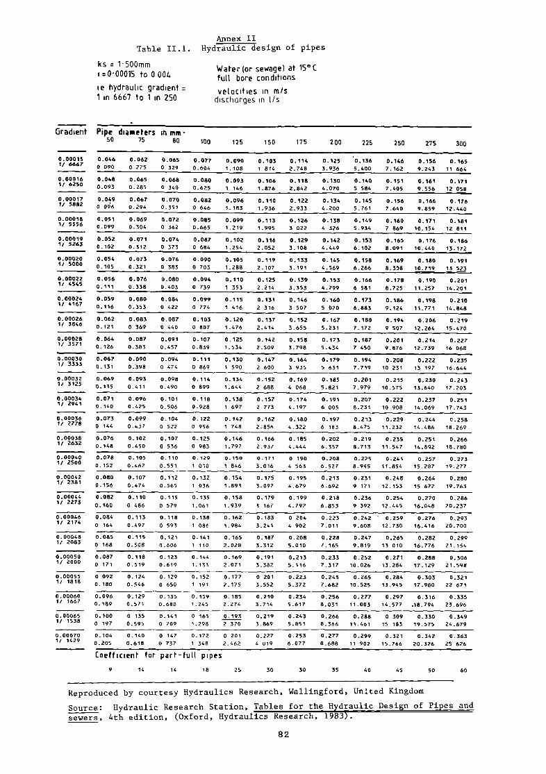
Annex IITable 11.1. Hydraulic design of pipes
ks 1500mm Water(or sewage) at 15°C1 ~O00015 to 0 004 fult bore condituons
ie hydrau(ic gradient velocities in mis1 in 6667 to un 250 dischcirges in 1/s
Coefficien~ for part-fuu pipes
9 14 14 18 25 30 30 35 40 45 50 60
Gradient Pipe diaMeters in mm50 75 80 100 125 150 175 200 225 250 275 300
0.103 0.114 0.125 0.1361 814 2.71.8 3.936
0.106 0.118 0.130
1.876 2.842
0.110
1.936
0.122
2.933
0.113
1.995
0.126
3 022
0.116
2.052
0.129
3.108
0.119
2.107
0.133
3.191
0.125
2.214
0.139
3.353
0.131 0.146
0.00015 0.0461/6667 0090
0.00016 0.0481/ 6250 0.093
0.00017 0.0491/ 5882 0 096
0.00018 0.0511/ 5556 0.099
0.00019 0.052Ii 5263 0.102
0.00020 0.0541/ 5000 0.105
0.00022 0.0561/ 4545 0.111
0.00024 0.0591/ 4167 0.116
0.00026 0.0621/ 3846 0.121
0.00028 0.0641/ 3571 0.126
0.00030 0.067
1/ 3333 0.131
0.00032 0.0691/ 3125
0.135
0.00034 0.0711/ 2941 0.140
0.00036 0.0731/ 2778 o 144
0.00038 0.0761/ 2632
0.148
0.00040 0.0781/ 2500 0.152
0.00042 0.0801/ 2381 0 - 156
0.00044 0.0821/ 2273 0.160
0.00046 0.0841/ 2174 0 164
0.00048 0.0851/ 2083 0 168
0.00050 0.0871/ 2000 0 171
0.00055 0 0921/ 1818 0.180
0.00060 0.0961/ 1667 0.189
0.00065 0.1001! 1538 0 197
0.00070 0.1041/ 1429 0 . 205
0.062 0.065
0275 0329
0.065 0.068
0.285 0 340
0.067 0.070
0.294 0.351
0.069 0.072
0.304 0 362
0.071 0.074
0.312 0 373
0.073 0.076
0.321 0 383
0.076 0.080
0.338 - 0.403
0.080 0.084
0.353 0 422
0.083 0.087
0 369 0 440
0.087 0.091
0.383 0.457
0.090 0.094
0.398 0 474
0.093 0.098
0.411 0.490
0.096 0.101
0.425 0.506
0.099 0.104
0.437 0 522
0.102 0.107
0.450 0 536
— 0.105 0.110
0.462 0.551
0.107 0.1120.474 0.565
0.110 0.115
0 486 0 579
0.113 0.1180497 0 593
0.115 0.121
0.508 0.606
0.118 0.1230.519 0619
0.124 0.129
0.546 0 650
0.129 0.135
0.571 0680
0 135 0.1410.595 0 709
0.140 0 147
0.618 0 737
0.077
0604
0.080
0.625
0.0820 646
0.085
0.665
0.087
0 684
0.090
0 703
0.094
0 739
0.099
0 774
0.103
0 807
0.1070.839
0.1110 869
0.114
0 899
0.118
0.928
0.122
0 956
0.125
0 983
0.129
1 010
0.132
1 036
0.135
1.061
0.138
1 086
0.141
1 110
0. 1441.133
0. 1521 191
01591.245
0 1651 . 298
0.1721 348
0.090
1.108
0.093
1 146
0.096
1.183
0.099
1219
0.102
1.254
0.105
1.288
0.110
1 353
0.115
1 416
0.120
1.476
0.125
‘.534
0.130
1 590
0.134
1.644
0.138
1 697
0.142
1 748
0.146
‘.797
0.1501 846
0.154
1.893
0.1581.939
0.162
1.984
0.1652.028
0.1692.071
0.177
7.175
0.1852 . 274
~0.1932 370
0 2012.462
4 .070
0.134
4 . 200
0.138
4 326
0.142
4.449
0.145
4.569
0.153
4 ?99
0.160
5 020
0.167
5.231
0.173
5.434
0.179
5 631
0.185
5 .821
0.191
6 005
0.197
6 183
0.202
6.357
0.208
6.527
0.213
6.692
0.2186.853
0.223
7.011
0.2287.165
0.233
7.317
0.245
7.682
0.2568.031
0.2668.366
0.2778.688
0.146 0.156 0.165
5.400 7.162 9.243 11 664
0.140 0.151 0.161 0.171
5 584 7.405 9.556 12 058
0.145 0.156 0.166 0.176
5.761 7.640 9.859 12.440
0.149 0.160 0.171 0.181
5.934 7 869 10.154 12 811
0.153 0.165 0.176 0.186
6.102 8.091 10.440 13.172
0.158 0.169 0.180 0.191
6.266 8.3~8 10.719 13 523
0.166 0.178 0.190 0.201
6 581 8.725 11.257 14.201
0.173 0.186 0.198 0.210
6.883 9.124 11.771 14.848
0.180 0.194 0.206 0.219
7172 9 507 12.264 15.470
0.187 0.201 0.214 0.227
7 450 9876 12.739 16 068
0.194 0.208 0.222 0.235
7.719 10 231 13 197 16644
0.201 0.215 0.230 0.243
7.979 10.575 13.640 17.203
0.207 0.222 0.237 0.251
8.231 10 908 14.069 17.743
0.213 0.229 0.244 0,258
8.475 11.232 14,486 18269
0.219 0.235 0.251 0.2668.713 11.547 14.8Q2 18.780
0.225 0.241 0.257 0.273
8.945 11.854 15.287 19,277
0.231 0.248 0.264 0.280
9 171 12.153 15 672 19.763
0.236 0.254 0.270 0.286
9 392 12.445 16.048 20.237
0.242 - 0.259 0.276 0.293
9.608 12.730 16.416 20.700
0.247 0.265 0.282 0.299
9.819 13 010 16.776 21154
0.252 0.271 0.288 0.306
10.026 13.284 17.129 21.59e
0.265 0.284 0.303 0.321
10.525 13.945 17.980 22 671
0.277 0.297 0.316 0.33511.003 14.577 .18.794 23.696
0.288 0 309 0.330 0.34911,461 15 183 19.575 24.679
0.299 0.321 0.342 0.36311 902 15.766 20.326 25 626
2 316
0.137
2.414
0.1422 . 509
0.147
2 600
0.152
2 688
0.157
2 773
0.162
2 . 856
0.1662 937
0.171
3.016
0.175
3. 092
0.1793 167
0.183
3.241
0. 1873.312
0.1913.382
0 2013.552
0.2103.714
0.2193.869
0.227
4 019
3 507
0.152
3.655
0.158
3.798
0.164
3 935
0.1694 068
0.1744197
0.1804.322
0.185
4.444
0 190
4 563
0.195
4679
0.1994 . 792
0 204
4 902
0.208
5.010
0.2135.116
0.223
5.372
0 . 234
5617
0.243
5 . 85 1
0 . 253
6,077
Reproduced by courtesy Hydraulics Research, Wallingford, United Kingdom
Source: Hydraulic Research Station, Tables for the Hydraulic Design of Pipes andsewers, 4th edition, (Oxford, Hydraulics Research, 1983).
82
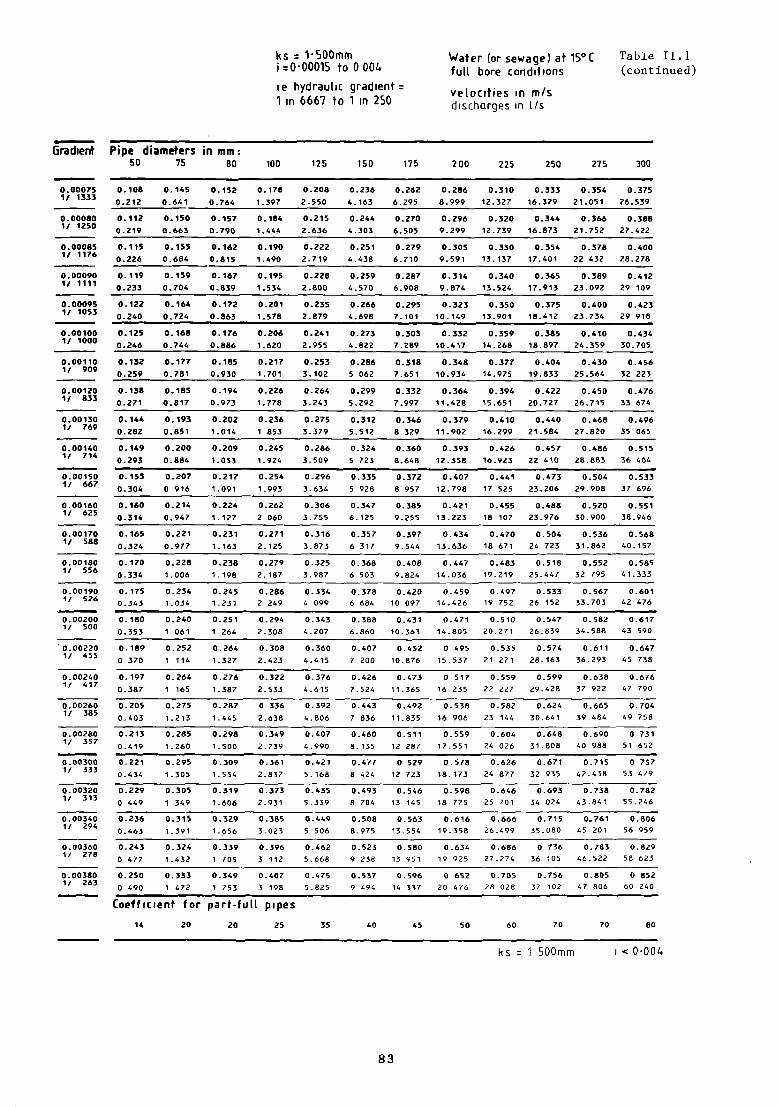
ks 1-500mm Water (or sewage) at 15°C Tabl& 11.1~000015 tO 0 006 full bore coriditions (continued)
ie hydraulic gradient ve(octties in m/s1 in 6667 to un 250 dtschcirqes in t/s
~radient Pipe diameters in mm:50 75 80 100
0.17e
1.397
0.184
1 •41.4
0. 190
1.490
0.195
1 .534
0.20 1
1.578
0.206
1.620
0.217
1.701
0.226
1.778
0.236
1 853
0.245
1.924
0.254
0.262
2 060
0.271
2.125
0.279
2.187
0.2862 249
0.294
2. 308
0.308
2.423
0.322
2.533
0 336
2 .638
0.349
2.739
0.36 1
2.837
0.373
2.931
0.385
3.023
0.396
3 112
0.407
3 198
125 150 175 200 225 250 275 300
0.208
2.550
0.215
2.636
0.222
2.719
0.228
2.800
0.235
2.879
0.24 1
2.955
0.253
3.102
0.264
3. 243
0.275
3.379
0.286
3-509
0.296
3.634
0.306
3.755
0.316
3 873
0.325
3. 987
0.334
4 099
0.343
4 . 207
0.360
4.415
0376
4.615
0.392
4 - 806
0.407
4.990
0.421
5.168
0.435
5-339
0.449
5 506
0.462
5 - 668
0475
5825
0. 000751! 1333
0. 000801/ 1250
0. 000851/ 1176
0. 000901~/ 1111
0.000951/ 1053
0.00 1001/ 1000
0.001101, 909
0. 001201/ 833
0. 00 1301/ 769
0. 001401, 714
0. 00 1501/ 667
0.00 1601/ 625
0. 00 1701/ 588
0. 00 1801/ 556
0. 00 1901/ 526
0.002001/ 500
‘0.002201/ 455
0.002401/ 417
0.002601/ 385
0.002801/ 357
0.003001/ 333
0. 003201/ 313
0.003401/ 294
0.003601/ 278
0. 003801/ 263
0.108 0.145 0.152
0.212 0.641 0.764
0.112 0.150 0.157
0.219 0.663 0.790
0.115 0.155 0.162
0.226 0.684 0.815
0.119 0.159 0.167
0.233 0.704 0.839
0.122 0.164 0.172
0.240 0.724 0.863
0.125 0.168 0.176
0.246 0.744 0.886
0.132 0.177 0.185
0.259 0.781 0.930
0.138 0.185 0.194
0.271 0.817 0.973
0.144 0.193 0.202
0.282 0.851 1.014
0.149 0.200 0.209
0.293 0.884 1.053
0.155 0.207 0.217
0.304 0 916 1.091
0.160 0.214 0.224
0.316 0.947 1.127
0.165 0.221 0.231
0.324 0.977 1.163
0.170 0.228 0.238
0.336 1.006 1.198
0.175 0.234 0.245
0.343 1.034 1.231
0.180 0.240 0.251
0.353 1 061 1 264
0.189 0.252 0.264
o 370 1 114 1.327
0.197 0.264 0.276
0.387 1 165 1.387
0.205 0.275 0.287
0.403 1.213 1.445
0.213 0.285 0.298
0.419 1.260 1.500
0.221 0.295 0.309
0.434 1.305 1.554
0.229 0.305 0.319
o 449 1 349 1.606
0.236 0.315 0.329
0.463 1.391 1.656
0.243 0.324 0.339
0 477 1.632 1 705
0.250 0.333 0.349
o 490 672 1 753
0.236 0.262 0.286 0.310 0.333 0.354 0.375
4.163 6.295 8.999 12.327 16.329 21.051 26.539
0.244 0.270 0.296 0.320 0.344 0.366 0.388
4.303 6.505 9.299 12.739 16.873 21.752 27.422
0.251 0.279 0.305 0.330 0.354 0.378 0.400
4.438 6.710 9.591 13.137 17.401 22 432 28.278
0.259 0.287 0.314 0.340 0.365 0.389 0.412
4.570 6.908 9.874 13.524 17.913 23.092 29 109
0.266 0.295 0.323 0.350 0.375 0.400 0.423
4.698 7.101 10.149 13.901 18.412 23.734 29918
0.273 0.303 0.332 0.359 0.385 0.410 0.436
4.822 7.269 10.417 14.268 18.897 24.359 30.705
0.286 0.318 0.348 0.377 0.404 0.430 0.456
5 062 7.651 10.934 14.975 19.833 25.564 32 223
0.299 0.332 0.364 0.394 0.422 0.450 0.476
5.292 7.997 11.428 15.651 20.727 26.715 33 674
0.312 0.346 0.379 0.410 0.440 0.468 0.496
5.512 8 329 11.902 16.299 21.584 27.820 35 065
0.324 0.360 0.393 0.426 0.457 0.486 0.515
5 723 8.648 12.358 16.923 22 410 28.883 36 404
0.335 0.372 0.407 0.441 0.473 0.504 0.533
5 928 8 957 12.798 17 525 23.206 29.908 37 696
0.347 0.385 0.421 0.455 0.488 0.520 0.551
6.125 9.255 13.223 18 107 23.976 30.900 36.946
0.357 0.397 0.434 0.470 0.504 0.536 0.568
6 317 9544 13.636 18 671 24 723 31.862 40.157
0.368 0.408 0.447 0.483 0.518 0.552 0.585
6 503 9.824 14.036 19.219 25.447 32 795 41.333
0.378 0.420 0459 0.497 0.533 0567 0.601
6 684 10 097 14.426 19 752 26 152 33.703 42 476
0.388 0.431 0.471 0.510 0.547 0.582 0.617
6.860 10.363 14.805 20.271 26.839 34.588 43 590
0.407 0.452 0 495 0.535 0.574 0.611 0.647
7 200 10.876 15.537 21 271 28.163 36.293 45 738
0.426 0.473 0 517 0.559 0.599 0.638 0.676
7.524 11.365 16.235 22 227 29.428 37 922 47 790
0.443 0.492 0.538 0.582 0.624 0.665 0.704
7 836 11.835 16 906 23 144 30.641 39 484 49 758
0.460 0.511 0.559 0.604 0.648 0.690 0 731
8.135 12 287 17.551 24 026 31.808 40 988 51 652
0.477 0 529 0.578 0.626 0.671 0.715 0 757
8 424 12 723 18.173 24 877 32 935 42.438 53 4P9
0.493 0.546 0.598 0.646 0.693 0.738 0.782
8 704 13 165 18 775 25 701 34 -024 43.841 55.246
0.508 0.563 0.616 0.666 0.715 0.761 0.806
6.975 13.554 19.358 26.499 35.080 45 201 56 959
0.523 0.580 0.634 0.686 0 736 0.783 0.829
9 238 13 951 19 925 27.274 36 105 46.522 58 623
0.537 0.596 0 652 0.705 0.756 0.805 0 852
9 494 14 337 20 476 28 028 37 102 47 806 60 240
Coefficient for part-full pupes
14 20 20 25 35 40 45 50 60 70 70 80
ks 1 SOOmm i < 0-004
83

Table 11.1
(continued)
ks 1-SOOmm
0-004 to 0-1ie hydrauluc graduent =
1 in 250 to 1 in 10
Water(or sewage) at 15°Cfull bore conditionsvelocitues in m/sdischarges in 1/s
Pipe diameters in mm-50 75 80 100 125 150 175 200 225 250 275 300
Gradient
0.004001/ 250
0.2560.503
0.3421.511
0.3581.799
0.4183.282
0.487
5.978
0.5519.743
0.61214.713
0.66921.013
0.72328.762
0.776
38.074
0.82649.057
0.87561.816
0.89663.353
0.004201/ 238
0.263
0.516
0.351
1.5490.36?1.844
0.4283.365
0.4996.127
0.5659.986
0.62715.080
0.68621.536
0.74129.478
0.79539.021
0.84650-.277
0.004401/ 227
0.2690.528
0.3591.586
0.3761.888
0.439
3.4450.511
6.273
0.579
10.224
0.642
15.438
0.702
22.0470.759
30.1770.614
39.9460.867
51.4680.917
64.854
0.004601/ 217
0.2750.540
0.3671.622
0.3841.931
0.4493.523
0.5236.416
0.592
10.4560.656
15.7880.718
22.5470.776
30.8600.832
40.8500.886
52.6330.938
66.320
0.004601/ 208
0.2810.552
0.3751.658
0.3931.973
0.458
3.600
0.5346.555
0.60510.683
0.671
16.1300.733
23.0350.793—
31.5290.850
41.7350.905
53.773
0.959
67.756
0.005001/ 200
0.2870.564
0.3831.692
0.4012.014
0.4683.675
0.5456.692
0.61710.905
0.68516.466
0.74823.514
0.$0932.184
0.86842.602
0.92454.889
0.97869.162
0.005501/ 182
0.301
0.5920.4021.776
0.4212.114
0.4913.857
0.5727.022
0.64611.443
0.71817.276
0.78524.671
0.84933.766
0.91144.695
0.97057.585
1.02672.558
0.006001/ 167
0.3150.618
0.4201.856
0.4402.209
0.5134.030
0.5987.337
0.67711.956
0.75018.051
0.82025.776
0.887
35.2780.951
46.6951.013
60.1611.072
75.802
0.006501/ 154
0.3280~,644
0.4381.933
0.4582.301
0.5344.197
0.6237.640
0.70412.448
0.781 -18.794
0.85426.836
0.924
36.728
0.99048.614
1.054
62.6321.116
78.915
0.007001/ 143
0.3410.669
0.454
2.007
0.475
2.3890.5554357
0.6467.931
0.73112.922
0.81119.508
0.88727.856
0.95938.123
1.02850.460
1.09565.009
1.15981.910
0.007501/ 133
0.3530.693
0.4702.078
0:492
2474
0.574
4.511
0.669
8.2120.75?
13.3790.840
20.1980.918
28.8400.993
39.4701.064
52.2411.133
67.3031.200
84.799
0.00800U 125
0.3650.716
0.4862.147
0.5082.556
0.5934 661
0.6918.484
0.78213.822
0.86720.865
0.94829.792
1.02540.772
1.09953.964
1.17069.522
1.23987.594
0.008501! 118
0.3760.738
0.5012.214
0.5242.635
0.612
4 8060.7138.747
0.80614.250
0.89421.512
0.97830.715
1.05742.034
1.13355.634
1.20v71.673
1.27890.303
0.00900
1/ 111
0.387
0.760
0.516
2.279
0.540
2.712
0.630
4.9460.7349 002
0.83014 666
0.92022.139
1.006
31 6111.088
43 2591.166
57.2551.242
73.7611.315
92 933
0.009501/ 105
0.3980.781
0.5302.342
0.5552.788
0.647
5.0830.7549 251
0.85315.071
0.94622.750
1.03432.482
1.11844.451
1.19958 832
1.276
75.792
1.351
95.491
0.010001/ 100
0.4080.802
0.5442.404
0.5692.861
0.6645.216
0.7749 493
0.87515.465
0.97123.345
1.06133 331
1.14765.612
1.23060.368
1.30977.770
1.38697.983
0.011001/ 91
0.4290.841
0.571
25220.5973.002
0.6975.473
0.8129 960
0.91816.225
1.01824.491
1.11334 967
1.20347.850
1.29063329
1.37481.583
1.454102736
0.012001/ 83
0.4480.879
0.5972.636
0.624
3 137
0.728
5.7180.848
10 4060.959
16.9511.064
25 5861.163
365301.257
49~9681.348
661581.435
852261.519
107 375
0.013001/ 77
0.4660.916
0.6212.744
0.6503.266
0.758
5.954
0.883
10 834
0.999
17.648
1.107
26.637
1.210
38.0291.309
52 0391.403
68 8711.494
88.7211.581
111 776
0.014001/ 71
0.4840.951
0.6452.849
0.6743.390
0.7876180
0.91611 246
1.03718 318
1.14927.648
1.256
39 472
1.358
54 012
1.456
71.482
1.550
92 083
1.641
116 012
0.0150011 67
0.5010.984
0.668
2 9500.6983 510
‘0.815
63990.94911.643
1.073
189641.190
28.6231.301
60.8641.406
55 9161.508
74.0011.605
95.3281.699
120099
0.016001/ 62
0.5181.017
0.6903.047
0.7213 626
0.8426 610
0.98012 027
1.10919.590
1.22929.567
1.36442.210
1.45357 75-8
1.55776.437
1.65898.466
1.755124051
0.017001/ 59
0.5341.049
0.711
3.142
0.744
3 7390.8686 815
1.01012 600
1.14320.196
1.26730 481
1.38543 515
1.49859.543
1.60578.799
1.709101507
1.809127.882
0.018001! 56
0.5501.079
0.7323.234
0.7663848
0.8937.014
1.04012 ‘61
1.17620784
1.30431 369
1.42544 782
1.54161 276
1.652
81 092
1.759
104 4601.862
131 607
0.019001/ ~
0.565 0.752 0.787 0.918 1.06913 113
1.20921.357
1.34032 232
1.46566.014
1.58462961
1.69783322
1.807107.332
1.913135220
ks 1-SOOmm
1.109 3.323 3.954 7 208
(oefficient for part—fuU pipes
18 25 30 35 45 50 60 70 80 90 100 110
1 ~ 0-1
84

ks 1-SOOmm Water lor sewage) at 15°C Table 11.1
0-004 to 01 full bore conditions (continued)
ie hydrautic gradient velocities in m/s
un 250 to un 10 discharges in 1/s
Gradient Pipe diameters in mm:50 75 80 100 125 150 175 200 225 250 275 300
0.580 0.772 0.807 0.942 1.096 1.240 1.375 1.503 1.625 1.742 1.854 1.9631.138 3.410 4.058 7.396 13.456 21.914 33.073 47.214 64.603 85.494 110.130 138.743
0.606 0.810 0.847 0.988 1.150 1.301 1.442 1.577 1.704 1.827 1.945 2.0591.195 3.578 4.257 7.759 15.116 22.989 34.695 49.528 67.768 89.682 115.523 145.536
0.636 0.846 0.885 1.032 1.202 1.359 1.507 1.647 1.780 1.908 2.032 2.1511.248 3.738 4.448 8.106 14.747 24.016 36.244 51.738 70.792 93.682 120.675 152.026
0.662 0.861 0.921 1.075 1.251 1.415 1.569 1.714 1.853 1.987 2.115 2.2391.300 3892 4.631 8.439 15.352 25.001 37.730 53.859 73.693 97.520 125.618 158.251
0.687 0.914 0.956 1.115 1.298 1.468 1.628 1.779 1.924 2.062 2.195 2.3241.349 4.040 4.807 8.760 35.934 25.949 39.159 55.899 76.483 101.212 130.373 164.241
0.711 0.947 0.990 1.155 1.344 1.520 1.685 1.842 1.991 2.134 2.272 2.4051.397 4 182 4.977 9.069 16.596 26.863 40.539 57.868 79.176 104.775 134.961 170.021
0.735 0.978 1.023 1.193 1.389 1.570 1.741 1.903 2.057 2.205 2.347 2.4641.443 4.320 5.141 9.368 17.040 27.748 41.873 59.772 81.781 108.221 139.399 175.611
0.758 1.008 1.054 1.230 1.431 1.619 1.795 1.961 2.120 2.273 2.419 2.5611.488 4.454 5.300 9.657 17.566 28.605 43.166 61 617 84.305 111.561 143.701 181.029
0.780 1.038 1.085 1.265 1.473 1.666 1.847 2.018 2.182 2.339 2.490 2.6351.531 4.584 5.455 9.939 18.078 29.437 44.422 63.409 86.756 114.804 147.87? 186 289
0.801 1.066 1.115 1.300 1.514 1.712 1.898 2.074 2.242 2.403 2.558 2.708
1.574 4.710 5.605 10.212 18.575 30.247 45.643 65.152 89.140 117.958 151.939 191.406
0.822 1.094 1.144 1.334 1.553 1.756 1.947 2.128 2.300 2.466 2.625 2.7781.615 4.833 5.751 10.479 19.059 31.035 46.832 66.849 91.462 121.030 155.895 196.389
0.843 1.121 1.173 - 1.367 1.592 1.800 1.995 2.181 2.357 2.527 2.690 2.8471.655 4.953 5.894 10.739 19.532 31.805 47.993 68.505 93.726 124.026 159.754 201.250
0.863 1.148 1.200 1.400 1.629 1.842 2.042 2.232 2.413 2.586 2.753 2.9141.694 5.071 6.033 10.993 19.993 32.555 49.125 70.121 95.938 126.951 163.522 205.996
0.882 1.174 1.227 1.431 1.666 1.884 2.088 2.282 2.467 2.644 2.815 2.9801.733 5 185 6.170 11 241 20.444 33.290 50.233 71 701 98.099 129.811 167.205 210.635
0.901 1.199 1.254 1.462 1.702 1.924 2.133 2.332 2.520 2.701 2.876 30441.770 5.297 6.303 11.484 20.886 34.008 51.316 73 247 100.214 132.610 170.809 215.174
0.920 1.224 1.280 1.492 1.737 1.964 2.178 2.380 2.573 2.757 2.935 3.1071.807 5.407 6.434 11.721 21.318 34.711 52.377 74 762 102.286 135.350 174.339 219.620
0.965 1.284 1.343 1.566 1.822 2.060 2.284 2.496 2.698 2.892 3.019 3.2591.896 5.672 6.749 12.296 22.362 36.411 54.941 78.420 107.290 161.971 182.866 230.361
1.009 1.341 1.403 1.635 1.904 2.152 2.386 2.607 2.819 3.021 3.216 3.4041.980 5.926 7.050 12.845 23.360 38.034 57.390 81.916 112.071 148 297 191.013 240.623
1.050 1.396 1.460 1.702 1.981 2.240 2.484 2.714 2.934 3.145 3.347 3.5432.062 6.169 7.340 13.371 24.316 39.592 59.740 85.268 116.657 154.365 198.827 250.466
1.090 1.449 1.516 1.767 2.057 2.325 2.578 2.817 3.045 3.264 3.474 3.6772.140 6.402 7.618 13.87e 25.237 41.090 62.000 88.494 125.070 160.203 206 346 259.937
1.128 1.500 1.569 1.829 2.129 2.407 2.668 2.916 3.152 3.378 3.596 3.8072.216 6.628 7.886 14.366 26.126 42.536 64.182 91.607 125.328 165.836 213.601 269.075
1.166 1.550 1.621 1.889 2.199 2.486 2.756 3.012 3.256 3.489 3.714 3.9322.289 6.846 8.146 14 839 26.985 43.935 66.291 94.617 129.446 171.285 220.618 277.914
1.202 1.598 1.671 1.948 2.267 2.563 2.841 3.105 3.356 3.597 3.829 4.0532.359 7.058 6.397 15 297 27.818 45.290 60.336 97 535 133.437 176.565 227.419 286.480
1.237 1.644 1.719 2.004 2.333 2.637 2.924 3.195 3.453 3.701 3.940 4.1712.428 7.263 8.642 15.742 28.626 46606 70 321 100.368 137.313 181.693 234.023 294.798
1.271 1.689 1.767 2.059 2.397 2.710 3.004 3.283 3.548 3.803 4.048 4.2852.495 7.463 8.879 16.175 29.413 47.887 72.252 103.124 141.082 186.680 240.446 302.888
1.304 1.733 1.613 2.113 2.459 2.780 3.082 3.368 3.641 5.902 4.154 4.3967.658 16.596 30 179 49.133 74.133 105 808 144.754 191.537 246.701 310 7682. 560 9.111
Coefficrent for part-full pipes20 35 35 45 50 70 80 90 100 110 120 130
ks 1-500mm < 0-1
0.020001/ 50
0. 022001/ 45
0. 024001~ 42
0. 026001/ 38
0. 028001/ 36
0.0300011 33
0. 032001/ 31
0.034001/ 29
0. 036001/ 28
0.038001/ 26
0.040001f 25
0. 042001/ 24
0.044001/ 23
0. 046001/ 22
0.048001/ 21
0. 050001/ 20
0. 055001/ 18
0.0600011 17
0.065001/ 15
0.070001/ 14
0.075001/ 13
0.080001/ 13
0.085001/ 12
0.090001/ 11
0.095001/ 11
0.100001/ 10
85
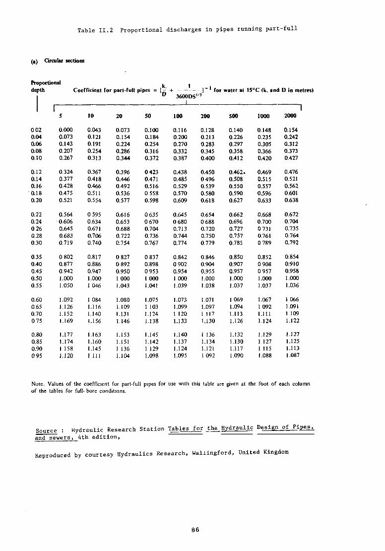
Table 11.2 Proportional discharges in pipes running part—full
(a) Grcuhr sections
Proportional k 1depth Coefîicient for pani-full pjp88 = [2 + — for waier ei 15°C(k. end 0 in melres)
0 36000S”31~
S 10 20 50 100 200 500 1000 2000
002 0.000 0.043 0.073 0.100 0.116 0.128 0.140 0.148 0.1540.04 0.073 0.121 0.154 0.184 0.200 0.213 0.226 0.235 0.2420.06 0.143 0.191 0.224 0.254 0.270 0.283 0.297 0.305 0.3120.08 0.207 0.254 0.286 0.316 0.332 0.345 0.358 0.366 0.3730.10 0.267 0.313 0.344 0.372 0.387 0.400 0.412 0.420 0.427
0.12 0.324 0.367 0.396 0423 0.438 0.450 0.462~ 0.469 0.4760.14 0.377 0.418 0446 0.471 0.485 0496 0.508 0.515 0.5210.16 0.428 0466 0.492 0.516 0.529 0.539 0.550 0.557 0.5620.18 0.475 0.511 0.536 0558 0.570 0.580 0.590 0.596 0.6010.20 0.521 0.554 0.577 0.598 0609 0618 0.627 0.633 0.638
0.22 0.564 0 595 0.616 0635 0645 0.654 0662 0.668 0.6720.24 0.606 0.634 0.653 0670 0680 0688 0.696 0700 0.7040 26 0.645 0.67 1 0.688 0.704 0.713 0.720 0.727 0 731 0.7350.28 0.683 0.706 0.722 0.736 0.744 0.750 0.757 0.761 0.7640.30 0.7 19 0740 0.754 0767 0.774 0.779 0.785 0 789 0.792
0.35 0802 0.817 0827 0837 0.842 0.846 0.850 0.852 0.8540.40 0.877 0.886 0892 0.898 0902 0.904 0.907 0908 09100.45 0.942 0.947 0.950 0953 0.954 0.955 0.957 0957 0.9580.50 1.000 1.000 1 000 1 000 1 000 1.000 1.000 L000 1.0000.55 1.050 1 046 1.043 1041 L039 L038 1.037 J~037 1.036
0.60 1.092 1 084 1.080 1.075 1.073 1.071 1 069 1.067 1 0660.65 1,126 1.116 1.109 1103 L099 1.097 1.094 1 092 1.0910.70 1.152 1.140 1131 1.124 1120 1117 L113 1.111 1109075 1.169 1.156 L146 1.138 1.133 1.130 1.126 1.124 1.122
080 1.177 1-163 1.153 1.145 1.140 1136 1.132 1.129 1.1270.85 1.174 1.160 1.151 1.142 1.137 1.134 1.130 1127 1.1250.90 1158 1145 1136 1129 1.124 1.121 1.117 1115 1.113095 1.120 1111 1.104 1.098 1.095 1092 1.090 1.088 1.087
Note. Valuesof the coefflcient for part-full pipes for use wlth this table aregiven at the foot of eachcolumnof the tablesfor full- bore condjtions.
Source Hydraulic ResearchStation Tables for the ~draulic Design of Pi2!.~
and sewers, 4th edition,
Reproduced by courtesy Hydraulics Research, Wallingford, United Kingdoin
86

Table 11,3 Proportjonal discharges in pipes running part—full
(a) Qrcular sections
Coefficieni for pan-Full pipes = + ~ for waier al 15°C(k, and 0 in metres)0 3600DS”3
10 20 50 100 200 500 1000 2000
0.000 0.000 0.0000.001 0.002 0.0020.003 0.005 0.0050.008 0.010 0.0110.014 0.016 0.018
0.022 0.02 5 0.0270.032 0.036 0.0380.044 0.048 0.05 10 058 0.063 0.0660.074 0 079 0.082
0.092 0.097 0.1000.112 0.117 0.1210.133 0139 0.1420.157 0.162 0.1650.181 0.187 0.190
0.250 0.255 0.2580.327 0.331 0.3330.411 0.413 0.4150500 0.500 0.5000592 0.589 0.588
0.684 0.679 0.6760 775 0.768 0.7630.861 0.852 0.8460.94 1 0.930 0.922
1.010 0.997 0.9891.064 1.051 1.0431 097 1.085 1.0771.099 1.090 1.084
0.000 0.001 0.001 0.0010.002 0.003 0.003 0.0030.006 0.007 0.007 0.0070.012 0.012 0013 0.0130019 0.020 0.021 0.021
0.029 0.030 0.03 1 0.03 10.040 0.041 0.042 0.0430.053 0.055 0.056 0.0570.068 0.070 0.07 1 0.0720.085 0.087 0088 0.089
0.104 0.105 0 107 0.1080.124 0.126 0.127 0.1280.145 0.147 0149 0.1500.169 0.171 0.172 0.1730.193 0 195 0 197 0.198
0.261 0263 0264 0.2650.336 0.337 0.338 0.3390.416 0.416 0417 0.4170.500 0500 0500 0.5000 587 0.586 0.585 0.585
0.673 0672 0.671 0.6690.759 0756 0755 0.7530 840 0 837 0.835 0.8320.916 0.912 0 909 0 906
0.982 0.977 0974 0.9711.035 1.030 1 027 1.023L070 1 066 1 063 1.0591.078 1.075 i072 1.069
0.001 0.0010.003 0.0030.007 0.0080.014 00140022 0.022
0.032 0.0320.044 0.0440057 0.0580.073 00740.090 0091
0.109 01100129 01300151 01520.174 0 1750199 0200
0266 02670.339 03400.418 04180500 05000584 0.584
0.669 06680351 07500.83 1 08290904 0902
0969 09671.021 10191 057 LOSS1068 1066
Note Valuesof the coefficient for part-full pipes for use with this table are given at the foot of eacli columnof the tablesfor fuil-bore conditsons.
Source: Hydraulic Research Station, Tables for the Hydraulic Design of Pipes
,
and sewers, 4th edition.
Reproduced by courtesy Hydraulico Research, Wallingford, England.
Proportionaldepth
5
0020.040.060.080.10
0.120.140.160.180.20
0.220.240.260.280.30
0.350.400.450.500.55
0.600.650700.75
0.800 850.900.95
87


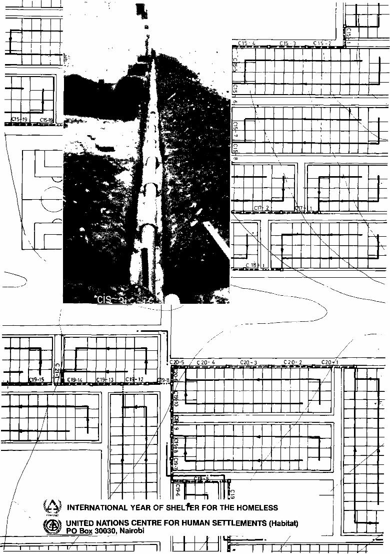
-.
b
cis~3j..,~i~
/ __
/
:20-5~‘
C20-~ C20-3 C2 0-E!
2 C20/1~ ~
~1.~
—rï—~I L~
t
— — — — — — — .,—,
- _ _
zi ---- --
2 11 1~j INTERNATIONAL YEAR OF SHELfrR FOR THE HOMELESS
(f~UNITED NATIONS CENTRE FOR HUMAN SETTLEMENTS (Habftat)
‘~ P0 Box 30030, Nairobi _________________________ //
ii 1 1 ~f1 - I ~ 1111111 ~,J-.
~—
~D4-
~1
(.5
‘.D.:~
-------c1~ ~—
/
-J~-
/7
/
.1
/— —
1 1i9-15
(-3
H/
C19—i~.
/
IQAI
;;
//
————————
/£i
14-
1
H
— ——
——~-
-~-~
~
1 111111/11 iII1~I