a measurement method using a modulated probe array …¤¾団法人 電子情報通信学会 the...
TRANSCRIPT

社団法人 電子情報通信学会
THE INSTITUTE OF ELECTRONICS,INFORMATION AND COMMUNICATION ENGINEERS
信学技報
TECHNICAL REPORT OF IEICE.
A Measurement Method Using a Modulated Probe Array for Phase of
Electromagnetic Field
Toru MIZUKAMIy, Qiang CHENy, and Kunio SAWAYAy
y Electrical and Communication Engineering, Graduate School of Engineering, Tohoku UniversityAramaki Aza Aoba 6-6-05, Aoba-ku, Sendai, 980{8579, Japan
Abstract A measurement method for phase of radiation åeld using modulated probe array is proposed. Exper-
imental investigation of phase measurement is performed to conårm the validity of the proposed method. It is
indicated that the measured phase almost agrees with theoretical data but improvement of the accuracy is required.
Key words Phase Measurement, EM Measurement, Radiation Eéciency, Modulation, Measurement Equipment
1. Introduction
Radiation pattern of antennas is usually measured by ro-
tating the antenna under test (AUT) on a turntable. This
conventional measurement requires several tens of seconds to
several minutes depending on the speed of the rotation and
the number of sampling points. Measurement of the radia-
tion eéciency of antennas by integrating the radiation power
on a closed surface [1] takes more than ten minutes when the
mechanical turntable and spherical scanner are used. How-
ever, in practical antenna design, it is strongly required to
reduce the measurement time to measure the 3-D radiation
pattern and the radiation eéciency of antennas.
In the EMC (Electromagnetic Compatibility) research, it
is required to measure the electromagnetic radiation such
as the leaked electromagnetic radiation from the electric de-
vices [2]. The radiated åeld should be measured simultane-
ously at several locations around electric devices in order
to estimate the source locations. Therefore, a method to
measure the electromagnetic radiation at several locations
simultaneously is necessary.
A measurement method using the modulated scattering
technique (MST) has been proposed to measure the electro-
magnetic åeld rapidly [3]- [7]. A simultaneous measurement
method using the parallel modulated probe array has been
also proposed by our research group [8]. Each modulated
probe element is modulated by a low-frequency modulation
signal with diãerent frequencies. The modulated signals are
combined and received by a wideband spectrum analyzer.
The measurement accuracy has been evaluated by measure-
ment of the radiation eéciency of antenna located in the
vicinity of head phantom and 3-D radiation pattern of an-
tennas.
However, the measurement system described above is ap-
plicable only for the magnitude of the radiation åeld and the
phase measurement method using modulated probe array is
required.
In this paper, a phase measurement method using the mod-
ulated probe array is proposed. Experimental investigation
is also performed with two modulated probes to conårmed
the validity of the proposed method.
Fig. 1 Conåguration of measurement system using parallel mod-
ulated probe array.
2. Measurement System Using Parallel
Modulated Probe Array
Fig. 1 shows the conåguration of the measurement sys-
tem using parallel modulated probe array. The probe array
consisting of 16 modulated probe elements is mounted on a
semicircular arch with equal angular spacing from 0 to 168.75
degrees in zenith angle. Each the modulated probe is com-
posed of a cross dipole antenna and a shielding box which
| 1 |
contains modulation circuit having a crystal generating a
local signal with individual frequency from 20 MHz to 40
MHz for modulating the received RF signal. The modulated
signals with diãerent frequencies are combined by RF com-
biners and delivered to a wideband spectrum analyzer. The
polarization of the modulated probe array can be switched
electrically. The electric circuit of each probe has also am-
pliåer and the equivalent gain of the modulated probe is 10
dBi at 1 GHz. The probe array together with an azimuth
turntable makes the system possible to measure the radia-
tion åeld on a spherical surface including the antenna under
test (AUT) located on the turntable. The measurement of a
full 3-D radiation pattern can be performed within about 16
seconds. The measurement system is located in a microwave
anechoic chamber. The manufactured measurement system
and the cross dipole antenna are shown in Fig. 2 and Fig. 3,
respectively. The speciåcations of the measurement system
are shown in Table 1. The isolation between the horizontal
antenna and the vertical antenna is greater than 30 dB.
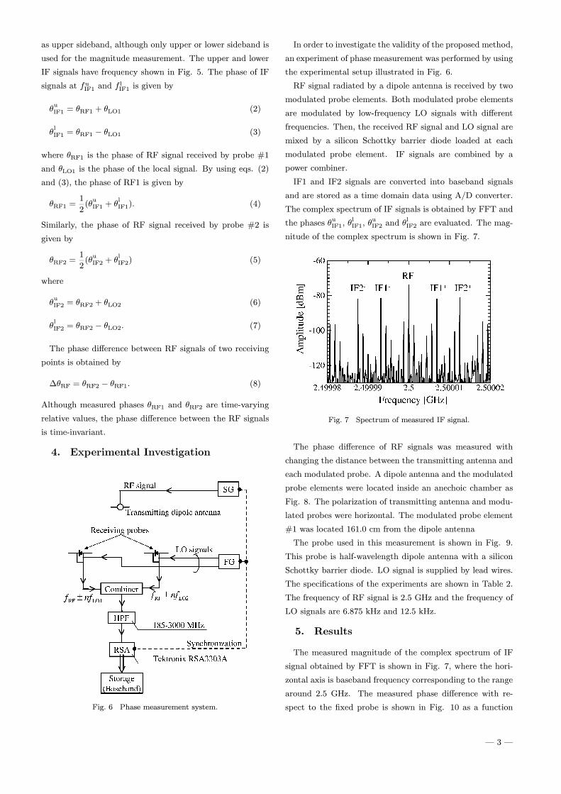
Fig. 4 shows the spectrum of IF signals measured by the
wideband spectrum analyzer, where 16 peaks of the IF sig-
nals at frequencies given by
fIF = fRF + fLO (1)
are observed. Each peak corresponds to the RF signal level
received by the 16 modulated probes when the RF frequency
is 1 GHz.
Fig. 2 Photo of measurement system using parallel modulated
probe array.
3. Phase Measurement Method
Although the system described above can be used for the
measurement of the magnitude of the radiation åeld, it can
not be used for phase measurement. In this section, a method
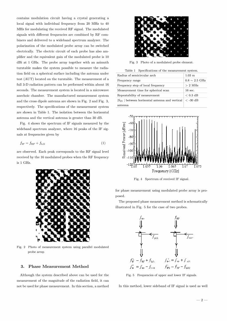
Fig. 3 Photo of a modulated probe element.
Table 1 Speciåcations of the measurement system.
Radius of semicircular arch 1.03 m
Frequency range 0.8 ò 2.5 GHzFrequency step of local frequency > 2 MHz
Measurement time for spherical scan 16 sec.
Repeatability of measurement < 0.3 dB
jS21 j between horizontal antenna and verticalantenna
< -30 dB
Fig. 4 Spectrum of received IF signal.
for phase measurement using modulated probe array is pro-
posed.
The proposed phase measurement method is schematically
illustrated in Fig. 5 for the case of two probes.
Fig. 5 Frequencies of upper and lower IF signals.
In this method, lower sideband of IF signal is used as well
| 2 |
as upper sideband, although only upper or lower sideband is
used for the magnitude measurement. The upper and lower
IF signals have frequency shown in Fig. 5. The phase of IF
signals at fuIF1 and flIF1 is given by
íuIF1 = íRF1 +íLO1 (2)
ílIF1 = íRF1 Ä íLO1 (3)
where íRF1 is the phase of RF signal received by probe #1
and íLO1 is the phase of the local signal. By using eqs. (2)
and (3), the phase of RF1 is given by
íRF1 =1
2(íuIF1 +í
lIF1): (4)
Similarly, the phase of RF signal received by probe #2 is
given by
íRF2 =1
2(íuIF2 +í
lIF2) (5)
where
íuIF2 = íRF2 +íLO2 (6)
ílIF2 = íRF2 Ä íLO2: (7)
The phase diãerence between RF signals of two receiving
points is obtained by
ÅíRF = íRF2 Ä íRF1: (8)
Although measured phases íRF1 and íRF2 are time-varying
relative values, the phase diãerence between the RF signals
is time-invariant.
4. Experimental Investigation
Fig. 6 Phase measurement system.
In order to investigate the validity of the proposed method,
an experiment of phase measurement was performed by using
the experimental setup illustrated in Fig. 6.
RF signal radiated by a dipole antenna is received by two
modulated probe elements. Both modulated probe elements
are modulated by low-frequency LO signals with diãerent
frequencies. Then, the received RF signal and LO signal are
mixed by a silicon Schottky barrier diode loaded at each
modulated probe element. IF signals are combined by a
power combiner.
IF1 and IF2 signals are converted into baseband signals
and are stored as a time domain data using A/D converter.
The complex spectrum of IF signals is obtained by FFT and
the phases íuIF1, ílIF1, í
uIF2 and í
lIF2 are evaluated. The mag-
nitude of the complex spectrum is shown in Fig. 7.
Fig. 7 Spectrum of measured IF signal.
The phase diãerence of RF signals was measured with
changing the distance between the transmitting antenna and
each modulated probe. A dipole antenna and the modulated
probe elements were located inside an anechoic chamber as
Fig. 8. The polarization of transmitting antenna and modu-
lated probes were horizontal. The modulated probe element
#1 was located 161.0 cm from the dipole antenna
The probe used in this measurement is shown in Fig. 9.
This probe is half-wavelength dipole antenna with a silicon
Schottky barrier diode. LO signal is supplied by lead wires.
The speciåcations of the experiments are shown in Table 2.
The frequency of RF signal is 2.5 GHz and the frequency of
LO signals are 6.875 kHz and 12.5 kHz.
5. Results
The measured magnitude of the complex spectrum of IF
signal obtained by FFT is shown in Fig. 7, where the hori-
zontal axis is baseband frequency corresponding to the range
around 2.5 GHz. The measured phase diãerence with re-
spect to the åxed probe is shown in Fig. 10 as a function
| 3 |
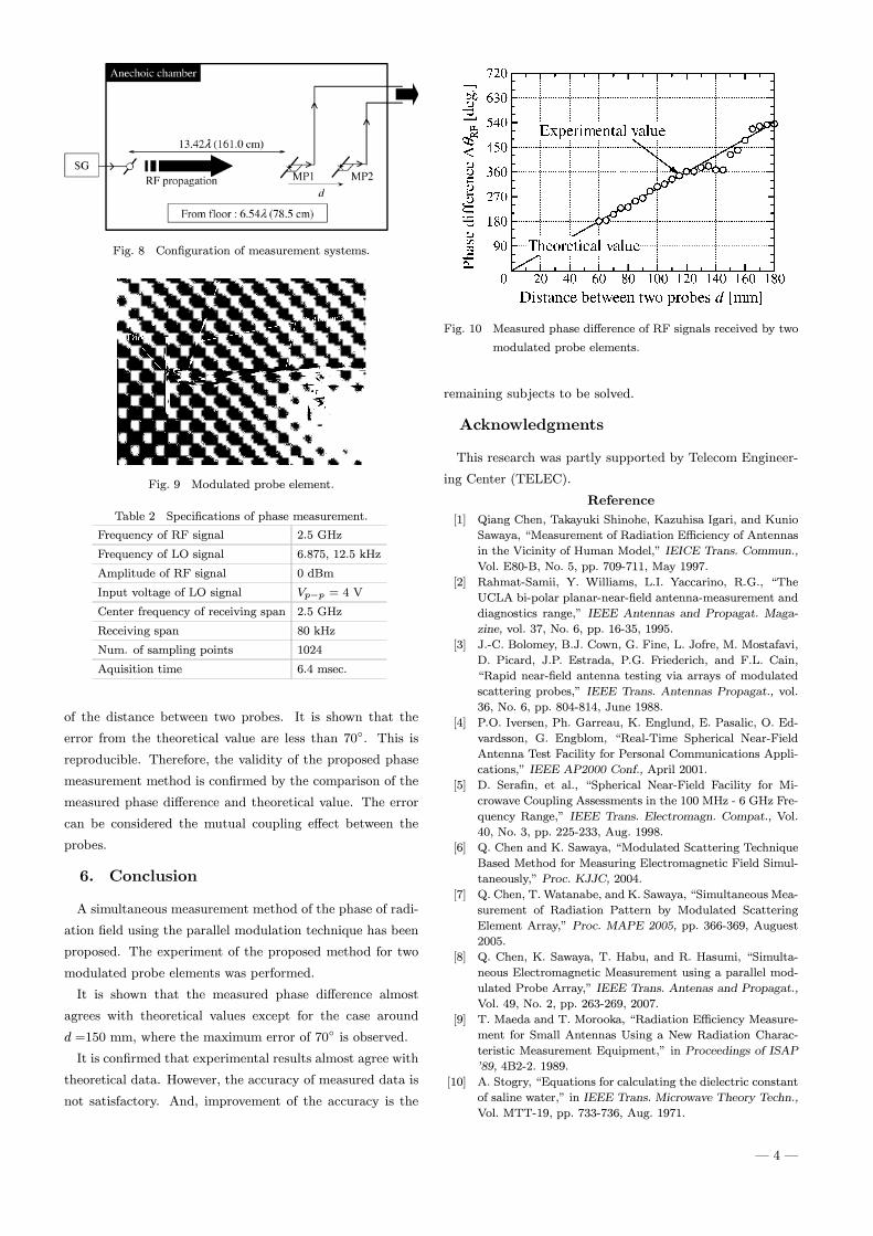
Fig. 8 Conåguration of measurement systems.
Fig. 9 Modulated probe element.
Table 2 Speciåcations of phase measurement.
Frequency of RF signal 2.5 GHz
Frequency of LO signal 6.875, 12.5 kHz
Amplitude of RF signal 0 dBm
Input voltage of LO signal VpÄp = 4 V
Center frequency of receiving span 2.5 GHz
Receiving span 80 kHz
Num. of sampling points 1024
Aquisition time 6.4 msec.
of the distance between two probes. It is shown that the
error from the theoretical value are less than 70é. This is
reproducible. Therefore, the validity of the proposed phase
measurement method is conårmed by the comparison of the
measured phase diãerence and theoretical value. The error
can be considered the mutual coupling eãect between the
probes.
6. Conclusion
A simultaneous measurement method of the phase of radi-
ation åeld using the parallel modulation technique has been
proposed. The experiment of the proposed method for two
modulated probe elements was performed.
It is shown that the measured phase diãerence almost
agrees with theoretical values except for the case around
d =150 mm, where the maximum error of 70é is observed.
It is conårmed that experimental results almost agree with
theoretical data. However, the accuracy of measured data is
not satisfactory. And, improvement of the accuracy is the
Fig. 10 Measured phase diãerence of RF signals received by two
modulated probe elements.
remaining subjects to be solved.
Acknowledgments
This research was partly supported by Telecom Engineer-
ing Center (TELEC).
Reference
[1] Qiang Chen, Takayuki Shinohe, Kazuhisa Igari, and Kunio
Sawaya, \Measurement of Radiation Eéciency of Antennas
in the Vicinity of Human Model," IEICE Trans. Commun.,
Vol. E80-B, No. 5, pp. 709-711, May 1997.
[2] Rahmat-Samii, Y. Williams, L.I. Yaccarino, R.G., \The
UCLA bi-polar planar-near-åeld antenna-measurement and
diagnostics range," IEEE Antennas and Propagat. Maga-
zine, vol. 37, No. 6, pp. 16-35, 1995.
[3] J.-C. Bolomey, B.J. Cown, G. Fine, L. Jofre, M. Mostafavi,
D. Picard, J.P. Estrada, P.G. Friederich, and F.L. Cain,
\Rapid near-åeld antenna testing via arrays of modulated
scattering probes," IEEE Trans. Antennas Propagat., vol.
36, No. 6, pp. 804-814, June 1988.
[4] P.O. Iversen, Ph. Garreau, K. Englund, E. Pasalic, O. Ed-
vardsson, G. Engblom, \Real-Time Spherical Near-Field
Antenna Test Facility for Personal Communications Appli-
cations," IEEE AP2000 Conf., April 2001.
[5] D. Seraån, et al., \Spherical Near-Field Facility for Mi-
crowave Coupling Assessments in the 100 MHz - 6 GHz Fre-
quency Range," IEEE Trans. Electromagn. Compat., Vol.
40, No. 3, pp. 225-233, Aug. 1998.
[6] Q. Chen and K. Sawaya, \Modulated Scattering Technique
Based Method for Measuring Electromagnetic Field Simul-
taneously," Proc. KJJC, 2004.
[7] Q. Chen, T. Watanabe, and K. Sawaya, \Simultaneous Mea-
surement of Radiation Pattern by Modulated Scattering
Element Array," Proc. MAPE 2005, pp. 366-369, Auguest
2005.
[8] Q. Chen, K. Sawaya, T. Habu, and R. Hasumi, \Simulta-
neous Electromagnetic Measurement using a parallel mod-
ulated Probe Array," IEEE Trans. Antenas and Propagat.,
Vol. 49, No. 2, pp. 263-269, 2007.
[9] T. Maeda and T. Morooka, \Radiation Eéciency Measure-
ment for Small Antennas Using a New Radiation Charac-
teristic Measurement Equipment," in Proceedings of ISAP
'89, 4B2-2. 1989.
[10] A. Stogry, \Equations for calculating the dielectric constant
of saline water," in IEEE Trans. Microwave Theory Techn.,
Vol. MTT-19, pp. 733-736, Aug. 1971.
| 4 |