a three pronged approach towards collaborative engineering filea three pronged approach towards ......
TRANSCRIPT

Nationaal Lucht- en Ruimtevaartlaboratorium National Aerospace Laboratory NLR
NLR-TP-2004-382
A three pronged approach towards collaborative engineering
E. Kesseler, E.H. Baalbergen and W.F. Lammen
This report has been based on a paper presented at the first Concurrent Engineering for space applications Workshop 2004, ESTEC Noordwijk, September 30th – October 1st 2004. This report may be cited on condition that full credit is given to NLR and the authors.
Customer: National Aerospace Laboratory NLR Working Plan number: AV.1.J.2 Owner: National Aerospace Laboratory NLR Division: Aerospace Vehicles Distribution: Unlimited Classification title: Unclassified September 2004 Approved by author:
Approved by project manager: Approved by project managing department:

-2-NLR-TP-2004-382
Summary
This paper describes the experiences obtained with three complementary approaches towardsthe integration of distributed engineering centres. The discussed cases involve aerospaceengineering activities. Given the similarities between this domain and the space domain, theobtained results are applicable for concurrent engineering of space applications as well. The firstexample describes the integration of black-box systems models into a single-site simulationmodel at the top system-level. The second example presents the workflow concept supportingorganisations to collaborate in the evaluation and validation of new design concepts. The lastexample discusses the integration of geographically dispersed real-time simulators of co-operating centres to arrive at a real-time synthetic environment to design and evaluate theproduct.

-3-NLR-TP-2004-382
Contents
1 Introduction 4
2 Simulation case study on co-operative level 52.1 State of the Art Description 52.2 Aircraft domain collaboration example 6
3 Workflow case study on co-ordinated level 8
4 Geographically distributed simulation case study on concerted level 124.1 State Of The Art Description 124.2 Air Transport Domain Example 15
5 Conclusions 17
Acronyms 17
References 18
(20 pages in total)
-4-NLR-TP-2004-382
1 Introduction
Collaborative engineering requires the participating parties to co-operate on the twoconceptually distinct levels:• On subject level. This level is also referred to as main business by [1] or, based on notions
from activity theory [2], as design rationale or future artefact by [3];• On organisational level, which [1] cites as meta communication or [3] cites as hypothetical
user activity.
For the organisational-level collaboration, [4] defines a five-level taxonomy for classifyingsupporting systems. The taxonomy starts with communicative collaboration up to concertedcollaboration. Each higher level extends the capabilities provided by the lower levels. On thecommunicative level, collaboration is limited to exchanging subject-level information via ashared, usually web-based repository. On collective level, also organisation-level information,like planning, resource tracking, etc, is exchanged via the shared repository. The co-operativelevel adds the sharing of common applications. However, each application is used locally onlocal copies of the information. The first case study elaborates this type of co-operation. Theco-ordinated level adds co-ordination between the distributed team members. The result is aco-ordinated flow of activities from one team member to another, where each team memberuses the result of the previous team member and in turn delivers its results to the next. This isalso referred to as workflows. The second case study presents an example of this type ofcollaboration. The concerted level extends this collaboration to support synchronous andasynchronous problem solving by a distributed team. The third case study falls in this category.
Between various distributed collaborative projects, organisational and technical situations varygreatly. To provide an overview of the variety of approaches to match these diverse challenges,the sequel elaborates three carefully chosen complementary case studies from the aerospacedomain. Each case will elicit the merits of the approach taken, concentrating on thecollaboration, to increase the relevance of the findings for the space domain.

-5-NLR-TP-2004-382
2 Simulation case study on co-operative level
This section is based on experience obtained in projects on co-operative level, which simulateintegrated systems.
2.1 State of the Art DescriptionIn system design, numerical simulation and optimisation of design objectives are commonlyused. Aerospace systems can be quite complex and are usually part of one or more "higherlevel" systems. To analyse the behaviour of the integrated system, the system model may becomposed of subsystem or component models from various suppliers. The physical behaviourof the sub-systems and components is a key determinant for the system behaviour. Therefore, itis important that this physical behaviour is adequately modelled, both with respect to thecomponent behaviour and with respect to system behaviour. Sometimes the model of thephysical behaviour of a (sub-)system or component may be too complex to be simulatedefficiently within the constraints of the integrated system model. Within such a system modelone or a few component models of extreme complexity may exist among several relativelysimple component models, resulting in an undesirable and unbalanced system model.Alternatively, in collaborative development projects, sub-system or component information maybe supplied from one company to another and therefore proprietary constraints may prevent theuse of detailed models of the physical behaviour of sub-systems or components. Somecomponent models are, for example, represented by no more than a table with measurementresults of the component behaviour. In such situations approximate representations based onsystem data sets can be used as effective and efficient alternatives.
A large variety of methods and tools is available for approximating system behaviour that isgiven by data sets. In order to collect and streamline some of the readily available functionalityfor approximation, a number of approximation methods has been integrated in a Matlab basedsoftware tool. This tool, named MultiFit and developed at NLR, provides a coherent andintuitive Graphical User Interface (GUI) to a variety of approximation methods based onpolynomial functions, splines, neural networks, radial basis functions and kriging models.Furthermore the MultiFit tool is equipped with facilities for inspection and analysis of the datasets and for automatic export of the approximate models to Modelica code. Modelica [5] is amodelling language for multi-physics applications. NLR uses Modelica as modelling platformfor the analysis of integrated system behaviour [6, 7, 8].
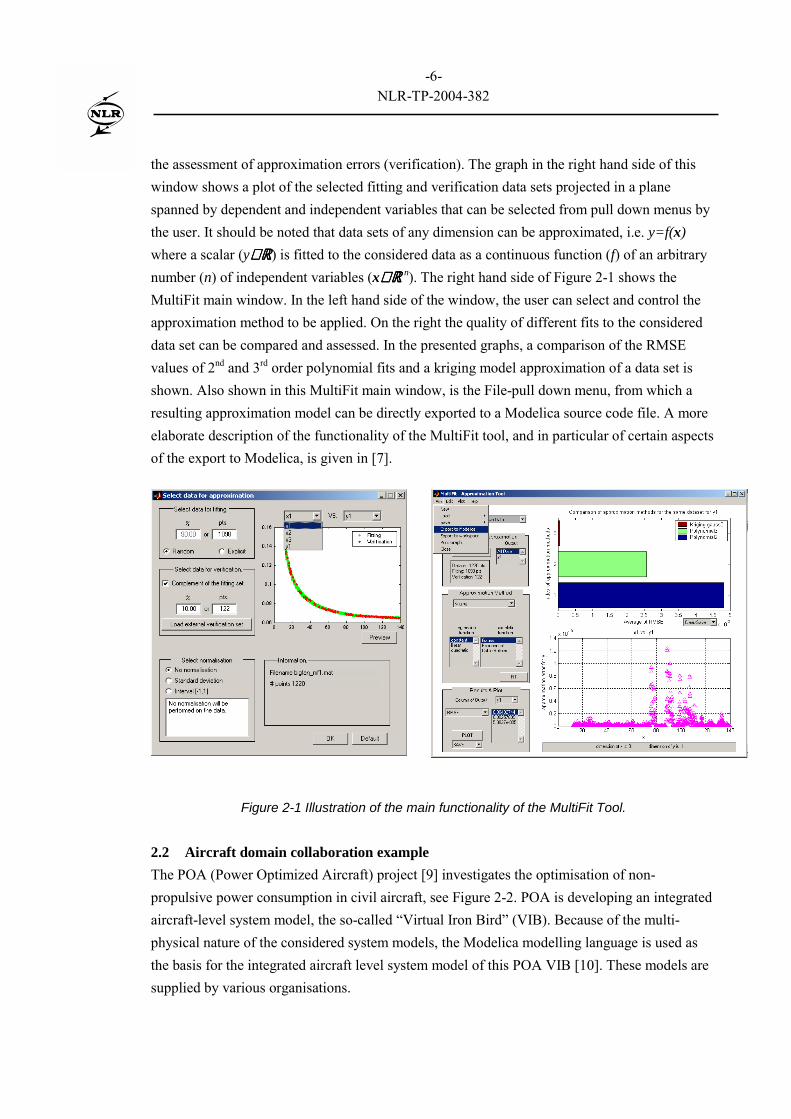
The functionality of MultiFit is illustrated in the Figure 2-1 below. On the left the MultiFit GUIwindow for data selection and inspection is shown. In the left hand side of this window the usercan divide the considered data set into separate data sets for the approximation (fitting) and for
-6-NLR-TP-2004-382
the assessment of approximation errors (verification). The graph in the right hand side of thiswindow shows a plot of the selected fitting and verification data sets projected in a planespanned by dependent and independent variables that can be selected from pull down menus bythe user. It should be noted that data sets of any dimension can be approximated, i.e. y=f(x)where a scalar (y∈∈∈∈ ℝℝℝℝ) is fitted to the considered data as a continuous function (f) of an arbitrarynumber (n) of independent variables (x∈∈∈∈ ℝℝℝℝ n). The right hand side of Figure 2-1 shows theMultiFit main window. In the left hand side of the window, the user can select and control theapproximation method to be applied. On the right the quality of different fits to the considereddata set can be compared and assessed. In the presented graphs, a comparison of the RMSEvalues of 2nd and 3rd order polynomial fits and a kriging model approximation of a data set isshown. Also shown in this MultiFit main window, is the File-pull down menu, from which aresulting approximation model can be directly exported to a Modelica source code file. A moreelaborate description of the functionality of the MultiFit tool, and in particular of certain aspectsof the export to Modelica, is given in [7].
Figure 2-1 Illustration of the main functionality of the MultiFit Tool.
2.2 Aircraft domain collaboration exampleThe POA (Power Optimized Aircraft) project [9] investigates the optimisation of non-propulsive power consumption in civil aircraft, see Figure 2-2. POA is developing an integratedaircraft-level system model, the so-called �Virtual Iron Bird� (VIB). Because of the multi-physical nature of the considered system models, the Modelica modelling language is used asthe basis for the integrated aircraft level system model of this POA VIB [10]. These models aresupplied by various organisations.

-7-NLR-TP-2004-382
Power supply and consumption aboard modern aircraft involves a large variety of systems thathave to operate in a wide range of conditions. Globally there are (groups of) systems of electric(e.g. generators, cabin equipment, avionics), mechanic (e.g. engine shafts, gearboxes),pneumatic (for example air-conditioning, which is part of the environment control system(ECS), wing ice protection system (WIPS)) and hydraulic (for example flight control system(FCS)) nature, and of combinations thereof. To investigate the operational behaviour of thesesystems under many different conditions, it is important to have integrated models incorporatingthese different systems.
Figure 2-2 Overview of the aircraft systems considered in the POA project.
Figure 2-3 illustrates an implementation of a simplified integrated aircraft model in theModelica based modelling and simulation environment Dymola [11]. In order to provide theengine power to the electric consumers, the (rotational) �mechanic� power of the engine shaft isconverted via a gearbox and a generator, which are also included in the integrated model. Toconnect the consumers to the engine, appropriate physical connector objects as provided byModelica are used. In this case the quantitative behaviour of some of the components (ECS andEngine) is based on data sets. These data sets may arise from complex system simulations (e.g.computationally expensive Computational Fluid Dynamics (CFD) simulations of the cabinairflow in the case of the ECS model) or experiments, which represent the underlying systembehaviour. A more detailed description on this case study can be found in [8].

-8-NLR-TP-2004-382
Figure 2-3 Dymola window showing the aircraft level integrated system model in Modelica.
To conclude, the combination of the NLR tool MultiFit with Modelica supports the full processfrom approximation of data sets to the integration with other multi-physics components forsystem optimisation. Specifically when models, delivered by various organisations, restrictinformation access or are computationally complex, the approximation approach promises to beuseful for integrated system design in a co-operative setting.
3 Workflow case study on co-ordinated level
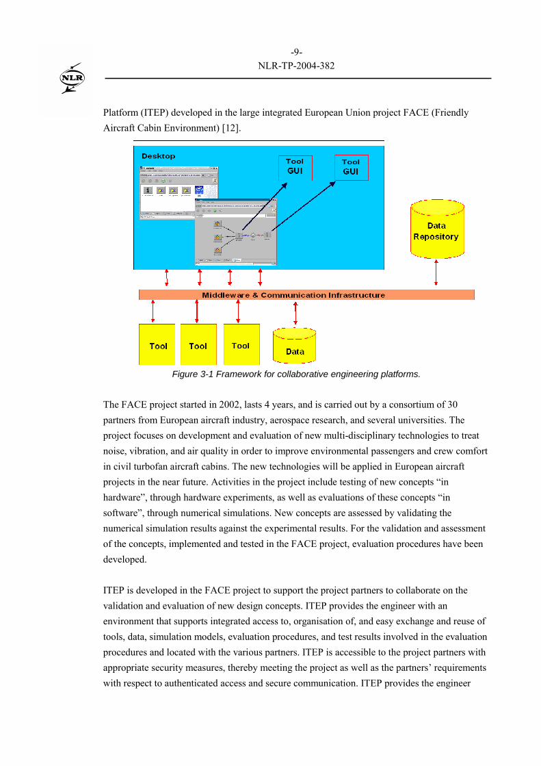
Experiences gained by NLR through the years, with multi-partner projects aimed to supportmultidisciplinary and collaborative engineering on the co-ordinated level, have been collected ina framework and supporting product suite. This framework, depicted in Figure 3-1, serves asblueprint for collaborative engineering platforms. Such platform provides the engineer withintegrated access to the resources (computers, tools, data sets) that support the engineeringactivities. A key element in the platform is the �workflow�, which allows definition andcontrolled and automated execution of a chain of tools. This concept supports the definition andapplication of engineering procedures. Realisation of a collaborative engineering platform issupported by a dedicated product suite, in which expertise in the area of constructingcollaborative engineering platforms has been translated to a set of generic tools. As an exampleof a collaborative engineering platform, we present the Integrated Technology Evaluation
-9-NLR-TP-2004-382
Platform (ITEP) developed in the large integrated European Union project FACE (FriendlyAircraft Cabin Environment) [12].
Figure 3-1 Framework for collaborative engineering platforms.
The FACE project started in 2002, lasts 4 years, and is carried out by a consortium of 30partners from European aircraft industry, aerospace research, and several universities. Theproject focuses on development and evaluation of new multi-disciplinary technologies to treatnoise, vibration, and air quality in order to improve environmental passengers and crew comfortin civil turbofan aircraft cabins. The new technologies will be applied in European aircraftprojects in the near future. Activities in the project include testing of new concepts �inhardware�, through hardware experiments, as well as evaluations of these concepts �insoftware�, through numerical simulations. New concepts are assessed by validating thenumerical simulation results against the experimental results. For the validation and assessmentof the concepts, implemented and tested in the FACE project, evaluation procedures have beendeveloped.
ITEP is developed in the FACE project to support the project partners to collaborate on thevalidation and evaluation of new design concepts. ITEP provides the engineer with anenvironment that supports integrated access to, organisation of, and easy exchange and reuse oftools, data, simulation models, evaluation procedures, and test results involved in the evaluationprocedures and located with the various partners. ITEP is accessible to the project partners withappropriate security measures, thereby meeting the project as well as the partners� requirementswith respect to authenticated access and secure communication. ITEP provides the engineer

-10-NLR-TP-2004-382
with an easy-to-operate, single computer that is tailored for the execution of evaluationprocedures.
ITEP comprises three main subsystems: Web Portal, Evaluation Data Repository, and WorkingEnvironment. The Web Portal is collection of web pages providing documentation, access to thehelp desk, and entry points to the other subsystems. The Evaluation Data Repository provides asingle repository for storing, searching, and retrieving the information (data, models, code,manuals) involved with the evaluation procedures, irrespective of the used file format. Therepository provides world-wide access via its web interface, controlled access to its contents,and automated configuration management, and hence is suited for the management of data incollaborative engineering environments. The Working Environment combines the availableresources, including computers, tools and data, into an easy-to-operate, single computer. Theengineer operates this computer using an intuitive graphical user interface, available via a webinterface. The GUI enables the user to manipulate data, to execute tools, and to define andexecute workflows, via simple point&click and drag&drop operations on icons in windows. Themajor goal of the Working Environment is to let the engineer concentrate on the actual jobinstead of struggling with computers, networking, scripts, programs, files, operating systems,and interfaces. An arbitrary tool may be integrated easily into the Working Environmentthrough tool wrapping, which allows integration of any legacy (including commercial) tool asis, without need for rebuilding the tool. The GUI of an integrated tool is that of the tool proper,but the Working Environment enables remote operation of the tool�s GUI. Integrated toolsprovide a uniform way for the engineer to start tools (thereby providing input data and tooloptions, and dealing with output data) and combine and use tools in workflows.
A workflow is a chain, or more precisely, a graph of tools. It may be composed by positioningtools and so-called data containers (representing data sets involved with the tools) on a canvas,and drawing connections among the tools and data containers; cf. Figure 3-2. In ITEP, aworkflow is used for definition and execution of evaluation procedures in terms of scenarioscomprising tools and data, which may be located with and owned by the various partners.Execution of a workflow typically involves the execution of tools running on, and exchange ofdata in a network of heterogeneous computing systems, which potentially spans parts of thepartners� networks. Mechanisms are available to co-ordinate the concurrent use of workflowsand workflow elements. As such, the workflow supports collaboration with respect toevaluation procedures, and, consequently, is an essential building stone for collaborativeengineering platforms.

-11-NLR-TP-2004-382
Figure 3-2 Example workflow in ITEP.
ITEP is implemented using the aforementioned product suite for realisation of collaborativeengineering platforms. The suite applies and combines state-of-the-art and off-the-shelftechniques (such as CORBA, JAVA and the web), middleware products, and securitytechnologies (e.g., virtual private networks, Secure Shell, Secure HTTP, signed applets) tosupport the realisation of platforms on top of existing infrastructures. The ITEP Evaluation DataRepository is realised as an instance of NLR�s Model and Simulator Repository (MSR) [13].The ITEP Working Environment is implemented using NLR�s SPINEware [14, 15]. CompleteITEP is available to the project partners as a web application. It is accessible over the Internet,via its Web Portal, faceitep.nlr.nl. The web interfaces of the subsystems collectively enable theusers to access the platform using the local desktop�s Java-enabled native browser, and hencemake the ITEP easily accessible to the engineers in the project. The web interface and theprovisions for concurrent access to and use of its contents, ensure that ITEP is a suitableplatform that serves the collaborative engineering needs of the FACE project, classified at theco-ordinated level.
-12-NLR-TP-2004-382
4 Geographically distributed simulation case study on concerted level
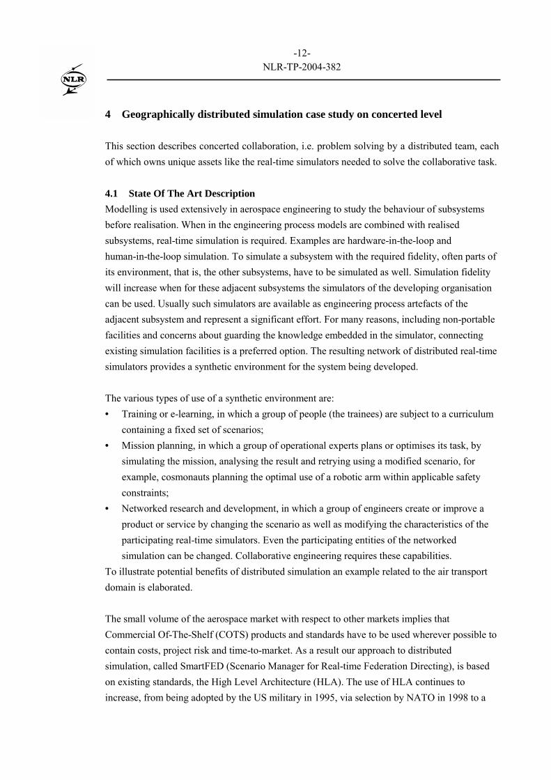
This section describes concerted collaboration, i.e. problem solving by a distributed team, eachof which owns unique assets like the real-time simulators needed to solve the collaborative task.
4.1 State Of The Art DescriptionModelling is used extensively in aerospace engineering to study the behaviour of subsystemsbefore realisation. When in the engineering process models are combined with realisedsubsystems, real-time simulation is required. Examples are hardware-in-the-loop andhuman-in-the-loop simulation. To simulate a subsystem with the required fidelity, often parts ofits environment, that is, the other subsystems, have to be simulated as well. Simulation fidelitywill increase when for these adjacent subsystems the simulators of the developing organisationcan be used. Usually such simulators are available as engineering process artefacts of theadjacent subsystem and represent a significant effort. For many reasons, including non-portablefacilities and concerns about guarding the knowledge embedded in the simulator, connectingexisting simulation facilities is a preferred option. The resulting network of distributed real-timesimulators provides a synthetic environment for the system being developed.
The various types of use of a synthetic environment are:• Training or e-learning, in which a group of people (the trainees) are subject to a curriculum
containing a fixed set of scenarios;• Mission planning, in which a group of operational experts plans or optimises its task, by
simulating the mission, analysing the result and retrying using a modified scenario, forexample, cosmonauts planning the optimal use of a robotic arm within applicable safetyconstraints;
• Networked research and development, in which a group of engineers create or improve aproduct or service by changing the scenario as well as modifying the characteristics of theparticipating real-time simulators. Even the participating entities of the networkedsimulation can be changed. Collaborative engineering requires these capabilities.
To illustrate potential benefits of distributed simulation an example related to the air transportdomain is elaborated.
The small volume of the aerospace market with respect to other markets implies thatCommercial Of-The-Shelf (COTS) products and standards have to be used wherever possible tocontain costs, project risk and time-to-market. As a result our approach to distributedsimulation, called SmartFED (Scenario Manager for Real-time Federation Directing), is basedon existing standards, the High Level Architecture (HLA). The use of HLA continues toincrease, from being adopted by the US military in 1995, via selection by NATO in 1998 to a
-13-NLR-TP-2004-382
general domain IEEE standard in 2000 [16, 17, 18]. Reflecting this HLA user base, each yearthree dedicated conferences are held [19]. Already in 2000, ESA determined that for the largeAutomated Transfer Vehicle programme, the distributed simulation approach is feasible. ESAestimated this approach would reduce costs and reduce time-to-market with 20% [20].
HLA provides an architecture to support component based simulation, with each real-timesimulator being a component. On each simulator site, the so-called Run Time Infrastructure(HLA-RTI) takes care of all communication. The COTS approach efficiently ensures that newhardware and software platforms will be supported, whenever they become available.Furthermore it facilitates provision of supporting tools, which any single application could notafford.
HLA allows each participating simulator to select the set of attributes of objects it will makeavailable to the other distributed simulators. Other objects can remain private and henceinaccessible for the other simulators amongst others to protect proprietary knowledge. TheSimulation Object Model (SOM) describes all data needed by and provided by a real-timesimulator. All data published in or subscribed to in the entire distributed simulation, orfederation in HLA parlance, is contained in the Federation Object Model (FOM). As long as theFOM vocabulary contains all data subscribed to by a simulator, that simulator can participate inthe federation. When another federate provides the same Simulation Object Model (e.g. anupdated, faster or more accurate version), it can replace the original simulator without affectingthe entire distributed simulation. This feature greatly improves the re-use of both simulators anddistributed simulations.
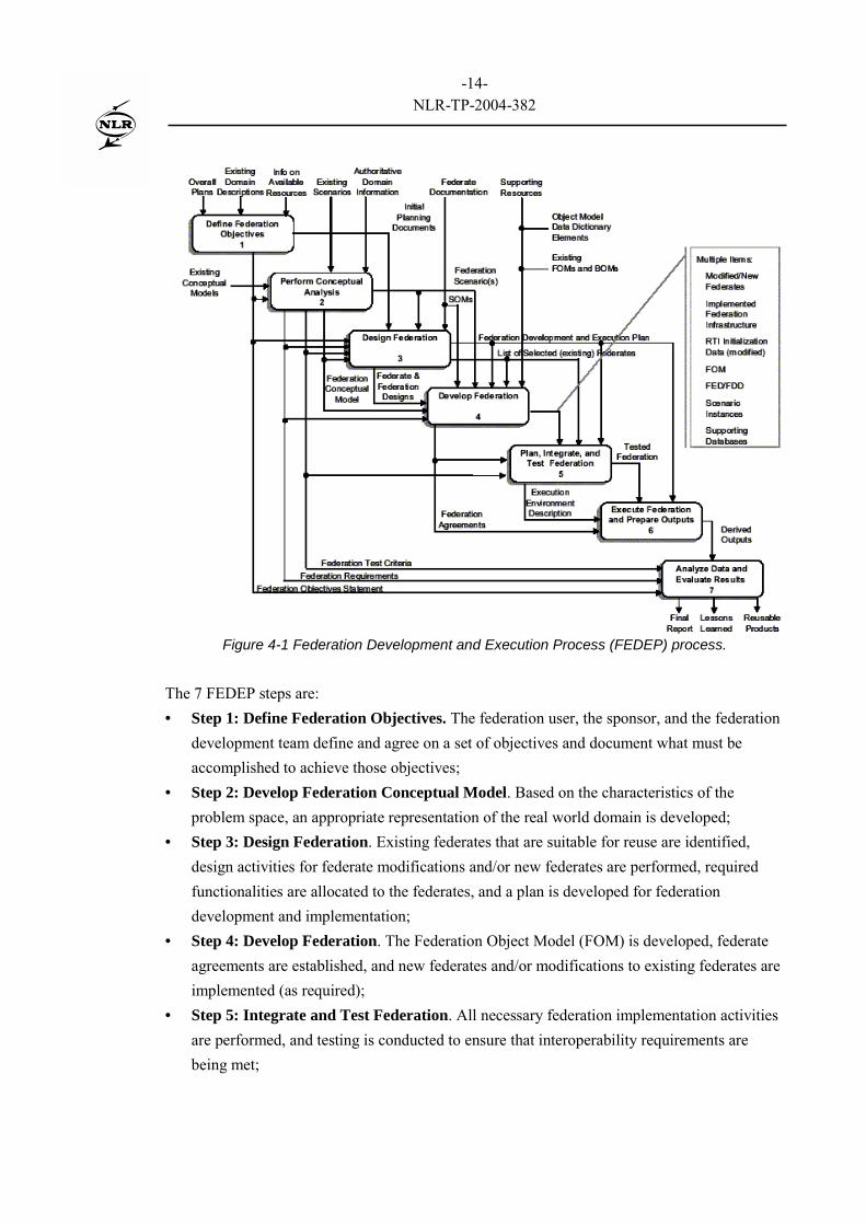
As the process of developing a distributed HLA simulation remains quite complicated, itevolved into the 7-step Federation Development and Execution Process (FEDEP) process. Toincorporate sufficient practical experience, FEDEP took an additional 3 years to mature beforebeing standardised [21]. The FEDEP is depicted in Figure 4-1.
-14-NLR-TP-2004-382
Figure 4-1 Federation Development and Execution Process (FEDEP) process.
The 7 FEDEP steps are:• Step 1: Define Federation Objectives. The federation user, the sponsor, and the federation
development team define and agree on a set of objectives and document what must beaccomplished to achieve those objectives;
• Step 2: Develop Federation Conceptual Model. Based on the characteristics of theproblem space, an appropriate representation of the real world domain is developed;
• Step 3: Design Federation. Existing federates that are suitable for reuse are identified,design activities for federate modifications and/or new federates are performed, requiredfunctionalities are allocated to the federates, and a plan is developed for federationdevelopment and implementation;
• Step 4: Develop Federation. The Federation Object Model (FOM) is developed, federateagreements are established, and new federates and/or modifications to existing federates areimplemented (as required);
• Step 5: Integrate and Test Federation. All necessary federation implementation activitiesare performed, and testing is conducted to ensure that interoperability requirements arebeing met;
-15-NLR-TP-2004-382
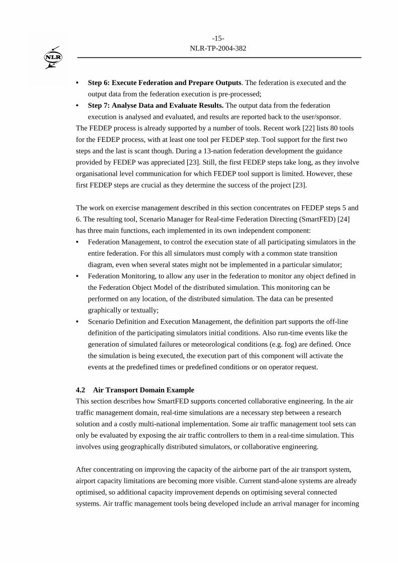
• Step 6: Execute Federation and Prepare Outputs. The federation is executed and theoutput data from the federation execution is pre-processed;
• Step 7: Analyse Data and Evaluate Results. The output data from the federationexecution is analysed and evaluated, and results are reported back to the user/sponsor.
The FEDEP process is already supported by a number of tools. Recent work [22] lists 80 toolsfor the FEDEP process, with at least one tool per FEDEP step. Tool support for the first twosteps and the last is scant though. During a 13-nation federation development the guidanceprovided by FEDEP was appreciated [23]. Still, the first FEDEP steps take long, as they involveorganisational level communication for which FEDEP tool support is limited. However, thesefirst FEDEP steps are crucial as they determine the success of the project [23].
The work on exercise management described in this section concentrates on FEDEP steps 5 and6. The resulting tool, Scenario Manager for Real-time Federation Directing (SmartFED) [24]has three main functions, each implemented in its own independent component:• Federation Management, to control the execution state of all participating simulators in the
entire federation. For this all simulators must comply with a common state transitiondiagram, even when several states might not be implemented in a particular simulator;
• Federation Monitoring, to allow any user in the federation to monitor any object defined inthe Federation Object Model of the distributed simulation. This monitoring can beperformed on any location, of the distributed simulation. The data can be presentedgraphically or textually;
• Scenario Definition and Execution Management, the definition part supports the off-linedefinition of the participating simulators initial conditions. Also run-time events like thegeneration of simulated failures or meteorological conditions (e.g. fog) are defined. Oncethe simulation is being executed, the execution part of this component will activate theevents at the predefined times or predefined conditions or on operator request.
4.2 Air Transport Domain ExampleThis section describes how SmartFED supports concerted collaborative engineering. In the airtraffic management domain, real-time simulations are a necessary step between a researchsolution and a costly multi-national implementation. Some air traffic management tool sets canonly be evaluated by exposing the air traffic controllers to them in a real-time simulation. Thisinvolves using geographically distributed simulators, or collaborative engineering.
After concentrating on improving the capacity of the airborne part of the air transport system,airport capacity limitations are becoming more visible. Current stand-alone systems are alreadyoptimised, so additional capacity improvement depends on optimising several connectedsystems. Air traffic management tools being developed include an arrival manager for incoming

-16-NLR-TP-2004-382
aircraft and a departure manager for departing traffic. To assess whether the proposed tool setco-operates as expected, a collaborative scenario is conceived in which an incoming flight isdelayed. In order for the transfer passengers to catch their connecting flight, the airline mightrequest landing priority for this flight with respect to its other incoming flights combined with arequest for a specified delay of the departing flight. Such scenario implies rescheduling ofincoming and departing aircraft. All of this has to be accomplished with minimal impact on theoverall air traffic system capacity and without compromising safety. A distributed simulationcan be made, consisting of an approach simulator containing the arrival manger, a flightsimulator for the late aircraft and an airfield simulator including the departure manager. Figure4-2 shows the resulting distributed simulation. More information on this example can be foundin [24]. In a similar case, integrating independent tools yielded the surprising finding that inspecial conditions the expected capacity gain could not be realised [25]. These conditionsoccurred sufficiently frequent to necessitate a redesign of the proposed tool set. Such resultsvindicate the need for collaborative engineering via distributed simulation prior to actual trialthat could endanger human life. Others, [23], also confirm that distributed simulation is a cost-effective and safe way to examine new concepts for systems-of-systems.
Figure 4-2 Example of collaborative engineering in air transport domain.

-17-NLR-TP-2004-382
5 Conclusions
Collaborative engineering can be beneficial in various situations. Examples are provided forcollaborative engineering on co-operative, co-ordinated and concerted levels. As the casestudies show, these different environments are best served with dedicated tools.
The combination of the NLR tool MultiFit with Modelica supports the full process fromapproximation of data sets to the integration with other multi-physics components for systemoptimisation. Specifically when models, delivered by various organisations, restrict informationaccess or are computationally complex, the approximation approach is useful for integratedsystem design in a co-operative setting.
Co-ordinated collaboration supports the flow of activities between distributed team members.Suitable supporting products such as SPINEware and MSR affordably provide significant valueto the user.
Concerted collaboration supports problem solving by a distributed team. As an example,properly deployed distributed simulations help the design of large interactingsystems-of-systems without jeopardising human life. High Level Architecture with itssupporting FEDEP processes and tools supports the creation of the synthetic environmentinvolved.
These case studies illustrate NLR�s comprehensive experience with the various types ofcollaborative engineering.
Acronyms
CFD Computational Fluid DynamicsCOTS Commercial Of-The-ShelfECS Environment Control SystemFACE Friendly Aircraft Cabin EnvironmentFCS Flight Control SystemFEDEP Federation Development and Execution ProcessFOM Federation Object Model (GUI Graphical User InterfaceHLA High Level ArchitectureITEP Integrated Technology Evaluation Platform

-18-NLR-TP-2004-382
MSR Model and Simulator RepositoryPOA Power Optimized AircraftRTI Run Time InfrastructureSmartFED Scenario Manager for Real-time Federation DirectingSOM Simulation Object ModelVIB Virtual Iron BirdWIPS Wing Ice Protection System
References
[1] Geisler C, Rogers E.R, �Technological mediation for design collaboration�, IEEEprofessional communication society international professional communication conferenceand 18th annual ACM international conference on Computer documentation, September2000.
[2] Leontjev A.N, Activity, consciousness and personality, Prentice-Hall, Englewood Cliff,NJ, USA, 1978.
[3] Tuikka T, �Remote concept design from an activity theory perspective�, 8th EuropeanConference of Computer-Supported Co-operative Work, September 2003.
[4] Romano N. C, Chen F., Nunamaker J. F, �Collaborative project management software�,35th HICSS, January 2002.
[5] Modelica Association (2002). Modelica - A Unified Object-Oriented Language forPhysical Systems Modeling - Language Specification (Version 2.0), http://modelica.org.
[6] Vankan W.J., Kos J, Lammen W.F, Approximation Models for Multi-DisciplinarySystem design - Application in a Design Study of Power Optimised Aircraft, Proc.Eurogen 2003 Conference, Spain, 2003. Also published as NLR-TP-2003-369.
[7] Lammen W.F, Vankan W.J., Maas R, Kos J, Approximation of black-box system modelsin Matlab with direct application in Modelica , Proc. 3rd International ModelicaConference, Linkőping, Sweden, http://modelica.org/Conference2003.shtml, 2003. Alsopublished as NLR-TP-2003-583.
[8] Vankan W.J, Lammen W.F, Kos J, Maas R, �Complementary Approximate modelling inMatlab and Modelica�. To be published in the proceedings of the EuroSim 2004conference, 2004
[9] POA - Power Optimised Aircraft Contract G4RD-CT-2001-00601 under the EuropeanCommunities 5th framework Programme for Research - Competitive and SustainableGrowth - Key Action, New Perspectives in Aeronautics. http://www.poa-project.com,2001.
-19-NLR-TP-2004-382
[10] [Bals J., Hofer G., Pfeiffer A, Schallert C. Object-oriented inverse modelling of multi-domain aircraft equipment systems with Modelica, Proc. 3rd International ModelicaConference, Linkőping, Sweden, http://modelica.org/Conference2003.shtml, 2003.
[11] Dynasim AB Developers of Dymola, http://www.dymola.com, 2004.[12] Paonessa A., "Friendly Aircraft Cabin Environment - FACE", 5th EURONOISE
Conference, Naples, May 19-21, 2003.[13] Moelands J.M, �Key features of the web-based Model and Simulator Repository MSR.
Version 2, NLR Technical Report NLR-TR-2004-262, June 2004.[14] Baalbergen E.H., Ven H. Van der, �SPINEware - a framework for user-oriented and
tailorable metacomputers�, Future Generation Computer Systems 15, (1999) 549-558.[15] �SPINEware more than just middleware�, http://www.spineware.com.[16] IEEE Standard for Modelling and Simulation (M&S) High Level Architecture (HLA) -
Framework and Rules, IEEE Std 1516-2000, September 2000.[17] [EEE Standard for Modelling and Simulation (M&S) High Level Architecture (HLA)
Federate Interface Specification, IEEE Std 1516.1-2000, September 2000.[18] EEE Standard for Modelling and Simulation (M&S) High Level Architecture (HLA) -
Object Model Template (OMT) Specification, IEEE Std 1516.2-2000, September 2000.[19] Simulation Interoperability Workshop, http://www.sisostds.org/.[20] Argüello L., Miró J., �Distributed Interactive Simulation for space projects�, ESA bulletin
102, May 2000.[21] IEEE Recommended Practice for High Level Architecture (HLA) Federation
Development and Execution Process (FEDEP), IEEE Std 1516.3-2003, April 2003.[22] Federation Development and Execution Process (FEDEP) tools in support of NATO
modelling and simulation (M&S) programmes, NATO TR-MSG-005, May 2004.[23] Reading R. et al, �Results and lessons learned from a multi-national HLA federation
development supporting simulation based acquisition�, EURO-SIW 2002, June 2002.[24] Kesseler E., �Deploying networked real-time simulation, putting the virtual enterprise to
work: Some aerospace experience�, 35th HICSS, January 2002. Also published as NLR-TP-2002-003.
[25] Kesseler E., Knapen E, �Designing future advanced controller displays�, InformationDesign Journal 2002/2003, p, 32-43, John Benjamins Publishing Company, ISSN: 0142-5471 E-ISSN: 1569-979X, 2003.

-20-NLR-TP-2004-382
Acknowledgement
The POA project has been partly funded under contract G4RD-CT-2001-00601 under theEuropean Communities 5th framework Programme for Research � Promoting Competitive andSustainable Growth � Key Action 4: �New Perspectives in Aeronautics�.The FACE project has been partly funded under contract G4RD-CT-2002-00764 under theEuropean Communities 5th framework Programme for Research, � Promoting Competitive andSustainable Growth � Key Action 4: �New Perspectives in Aeronautics�.