a time error correction method applied to high-precision aer asynchronous cmos image sensor...
TRANSCRIPT
A Time Error Correction Method Applied to High-Precision AER Asynchronous CMOS Image Sensor
李东盛
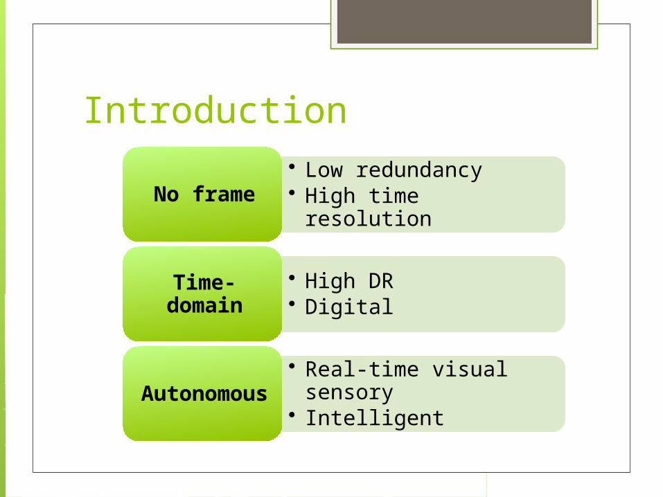
Introduction
• Low redundancy• High time resolutionNo frame
• High DR• Digital
Time-domain
• Real-time visual sensory
• Intelligent
Autonomous
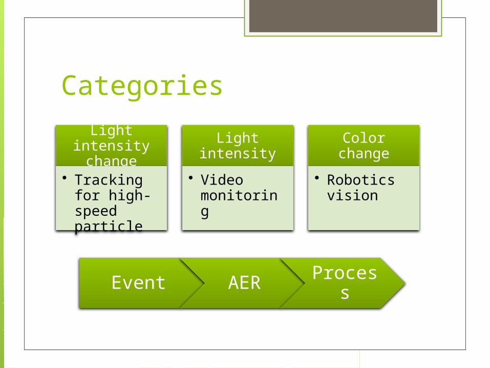
Categories
Light intensity change
• Tracking for high-speed particle
Light intensity
• Video monitoring
Color change
• Robotics vision
Event AER Process
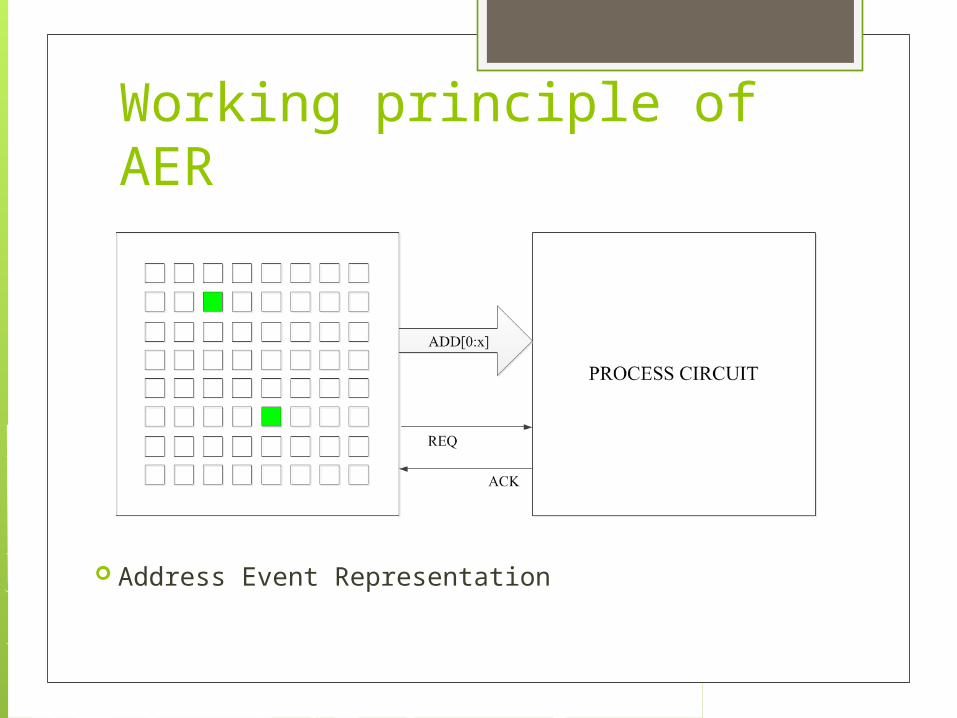
Working principle of AER
Address Event Representation
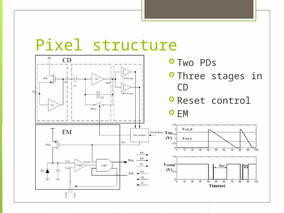
Pixel structure Two PDs Three stages in
CD Reset control EM

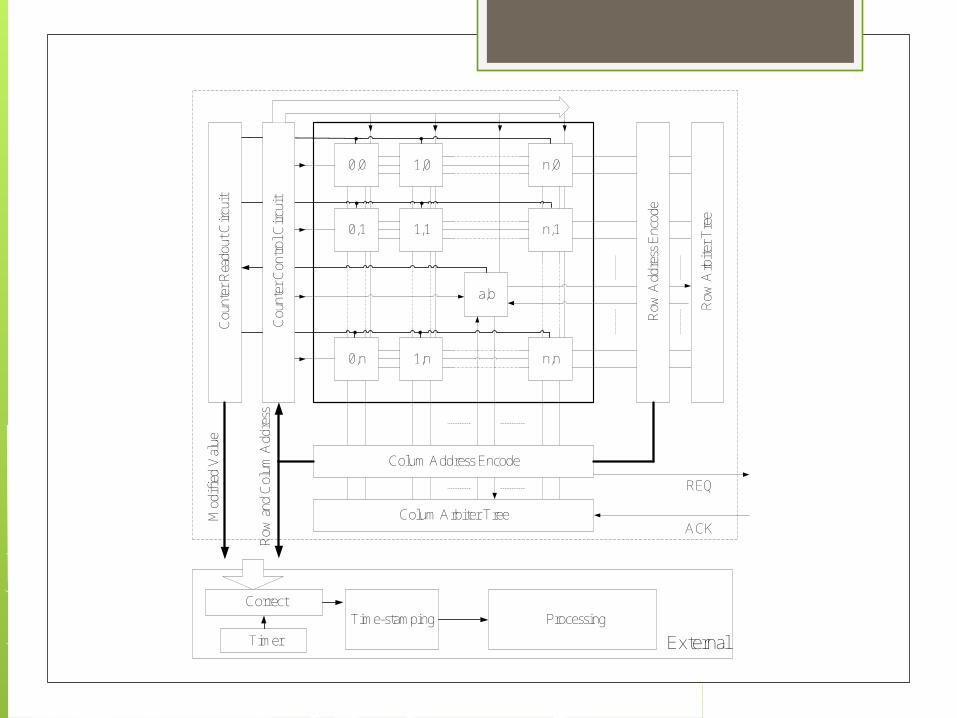
Pixel Array Pixel → Row arbiter →
Row address encoder → pixel → Column arbiter → Column address encoder → external → pixel
Because the time-stamping of the AER asynchronous image sensors is made in the external, so the time of making time-stamping is not the accurate time when the pixel generates pulse events.
0,0
0,1
0,n 1,n
1,1
1,0 n,0
n,1
n,n
a,b
Row
Add
ress
Enc
ode
Row
Arb
iter
Tre
e
Colum Address Encode
Colum Arbiter Tree
AER[0:x]
REQ
ACK

The Arbiterreq0
req1
ack0
ack1
req2
req3
ack2
ack3
req(n-1)
req(n)
ack(n-1)
ack(n)
treq
treq
tack
tack
tack-ME
tsw
treq
MEackackreqab ttitiT )1(
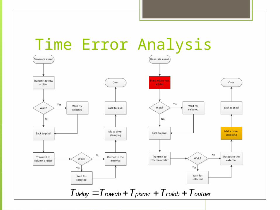
Time Error Analysis
outaercolabpixaerrowabdelay TTTTT

Time Error Analysis Single event
Two events(in an 8×8 pixel array)
Tp1 is the delay of external processing and acknowledgment(Mainly determined by the external processing speed)
Tdelay2
outaercolabpixaerrowabdelay TTTTT MEackackreqrowab ttntnT )1(
MEackackreqcolab ttntnT )1(
MEackackreqoutaerpixaerdelayerror tttTTTT 25711
2112 delaypdelayerror TTTT

(a) (b) (c)
If the two events are in the different rows
In Fig. 5 Trowab Tdelay2
(a)
(b)
(c)
acksw tt outaerpixaerMEackreqacksw TTtttt 44
ackswreq ttt 2 outaerpixaerMEackreqacksw TTtttt 55
ackswreq ttt 32 outaerpixaerMEackreqacksw TTtttt 66
(a) (b) (c) (d)
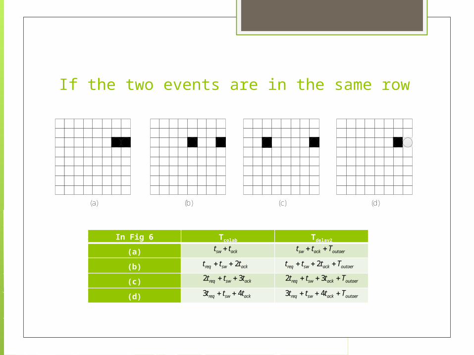
If the two events are in the same row
In Fig 6 Tcolab Tdelay2
(a)
(b)
(c)
(d)
acksw tt outaeracksw Ttt
ackswreq ttt 2 outaerackswreq Tttt 2
ackswreq ttt 32 outaerackswreq Tttt 32
ackswreq ttt 43 outaerackswreq Tttt 43
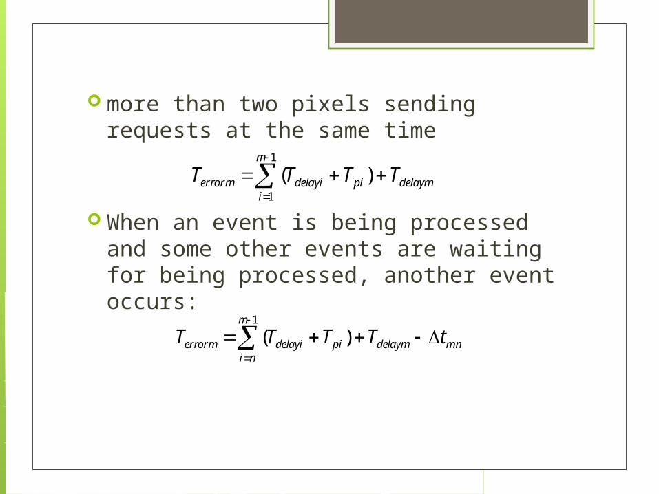
more than two pixels sending requests at the same time
When an event is being processed and some other events are waiting for being processed, another event occurs:
1
1
)(m
idelaympidelayierrorm TTTT
mn
m
nidelaympidelayierrorm tTTTT
1
)(
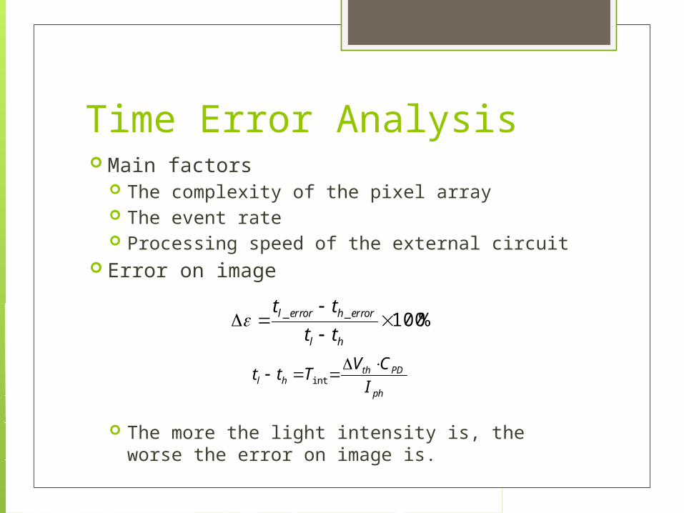
Time Error Analysis Main factors
The complexity of the pixel array The event rate Processing speed of the external circuit
Error on image
The more the light intensity is, the worse the error on image is.
%100__
hl
errorherrorl
tt
tt
ph
PDthhl I
CVTtt
int
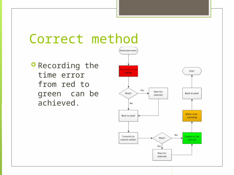
Correct method
Recording the time error from red to green can be achieved.
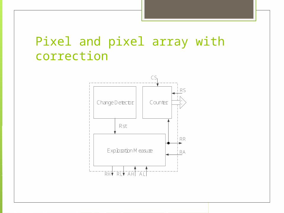
Pixel and pixel array with correction
Change Detector
Exploration Measure
Counter
Rst
RR
RA
RS
CS
RH RL AH AL
C
0,0
0,1
0,n 1,n
1,1
1,0 n,0
n,1
n,n
a,b
Row
Add
ress
Enc
ode
Row
Arb
iter
Tre
e
Colum Address Encode
Colum Arbiter Tree
REQ
ACK
Cou
nter
Rea
dout
Cir
cuit
Cou
nter
Con
trol
Cir
cuit
Mod
ifie
d V
alue
Row
and
Col
um A
ddre
ss
Timer
CorrectTime-stamping Processing
External
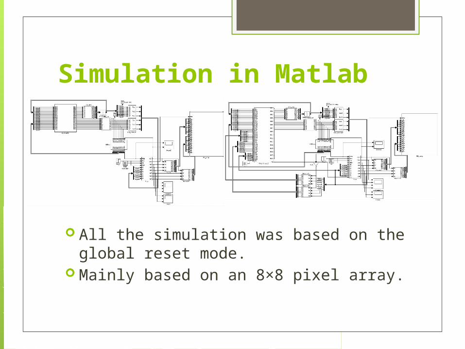
Simulation in Matlab
All the simulation was based on the global reset mode.
Mainly based on an 8×8 pixel array.
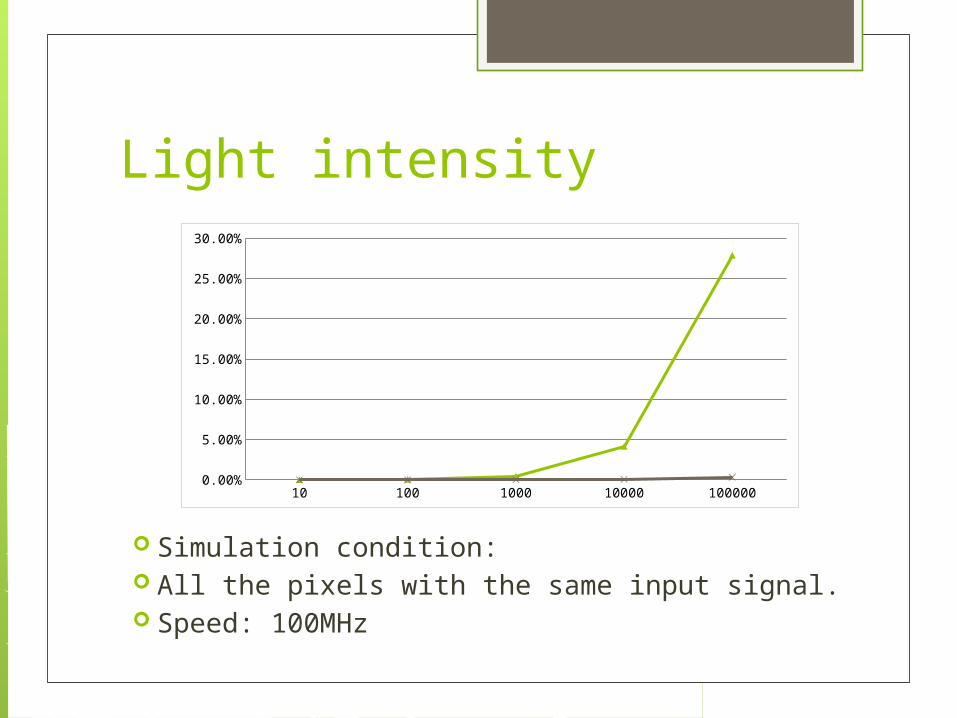
Light intensity
10 100 1000 10000 100000
line 1 0.0001 0.0006 0.0043 0.0415 0.2789
line 2 0.000001 0 0.0001 0.0005 0.0031
2.50%
7.50%
12.50%
17.50%
22.50%
27.50%
Simulation condition: All the pixels with the same input signal. Speed: 100MHz
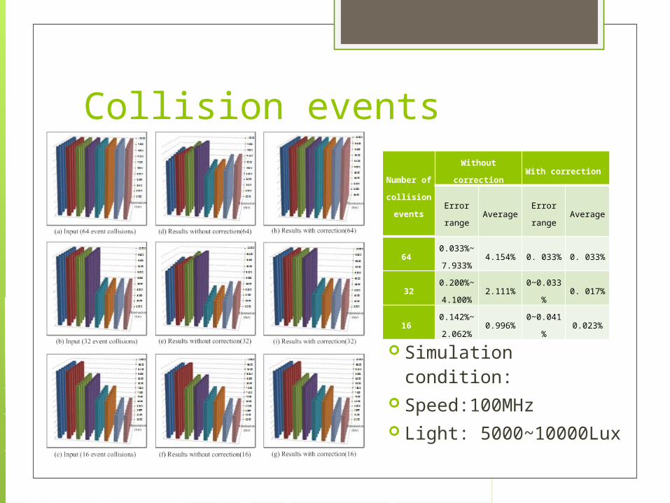
Collision events
Number
of
collision
events
Without
correctionWith correction
Error
rangeAverage
Error
rangeAverage
64
0.033%
~7.933
%
4.154% 0. 033% 0. 033%
32
0.200%
~4.100
%
2.111%0~0.033
%0. 017%
16
0.142%
~2.062
%
0.996%0~0.041
%0.023%
Simulation condition: Speed:100MHz Light:
5000~10000Lux
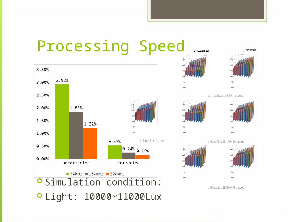
Processing Speed
9000
9500
10000
10500
11000
11500
9000
9500
10000
10500
11000
11500
9000
9500
10000
10500
11000
11500
9000
9500
10000
10500
11000
11500
(a) Input illumination
(b) Results with 50MHz speed
(c) Results with 100MHz speed
(d) Results with 200MHz speed
9000
9500
10000
10500
11000
11500
9000
9500
10000
10500
11000
11500
9000
9500
10000
10500
11000
11500
Uncorrected Corrected
uncorrected corrected0.00%
0.50%
1.00%
1.50%
2.00%
2.50%
3.00%
3.50%
2.92%
0.53%
1.85%
0.24%
1.22%
0.16%
50MHz 100MHz 200MHz
Simulation condition: Light: 10000~11000Lux
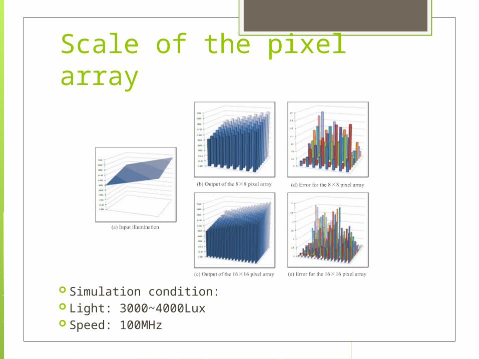
Scale of the pixel array
Simulation condition: Light: 3000~4000Lux Speed: 100MHz
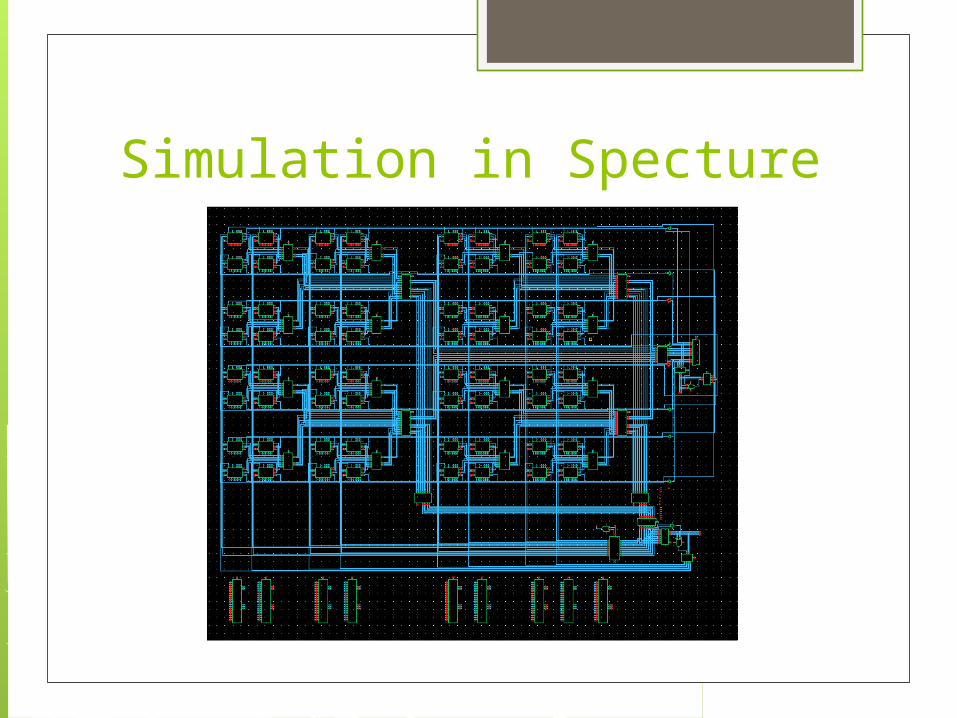
Simulation in Specture

Signals in CD unit
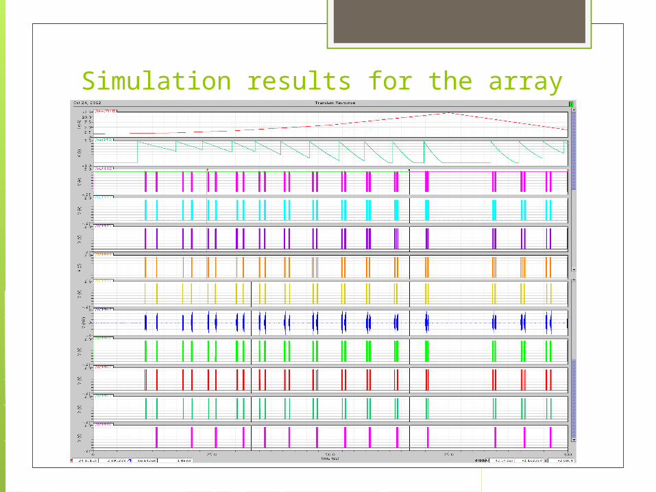
Simulation results for the array


THANK YOU~