atf2 - fermilab · 2011-12-06 · atf2 : goal - i a. achievement of 37nm beam size a1)...
TRANSCRIPT

ATF2
T. Tauchi, ILC PAC, 14 -15 November 2011, Institute of Physics, Academy of Sciences, Prague
2011年 11月 13日 日曜日

ATF2 Final GoalEnsure collisions between nanometer
beams; i.e. luminosity for ILC experiment
FACILITYconstruction,first result
ATF2/KEK; 1.3GeV2005-08-11?
FFTB/SLAC; 47GeV1991-93-94
OpticsLocal chromaticity
correction scheme; very short and longer L*
(β*y=100μm, LFF=30m)
Non-local and dedicated CCS at upstream; high symmetry in x, y ; i.e. orthogonal tuning
(β*y=100μm, LFF=185m)
Design beam size
2.3μm / 34nm, aspect=82(γεy=3 x 10⁻⁸ m)
1.92μm /52nm, aspect=37(γεy=2 x 10⁻⁶ m)
Achieved ? 70nm ( FD jitter remains !)
Reduction of Risk at ILC Optics and bean tuningStabilization
2011年 11月 13日 日曜日

Optics design choice(1) Non-local correction
A plan of KEK-ATF Final Focus Test Beam Line (ATF2)!
Shigeru Kuroda, J.Urakawa, H.Hayano, K.Kubo, T.Okugi, S.Araki, N.Toge, T.Matsuda and T.Tauchi
High Energy Accelerator Research Organization(KEK), 1-1 Oho, Tsukuba-shi, Ibaraki, Japan
Abstract
This report describes one of the possible programs which
is being investigated as the near-future extension of Ac-
celerator Test Facility (ATF) at KEK. In this program, a
36.6m long final focus test beam line, which we call ATF-
2, adopts the new final focus optics proposed by P. Rai-
mondi and A. Seryi. The goal of ATF-2 will be to test ex-
perimentally this new optics and to realize the beam size
of 50nm or less for the E = 1.5GeV beam extracted
from ATF. We present in this short report the basic design
of ATF-2, results of tracking simulation and a simulation
study of a possible beam tuning procedure.
1 INTRODUCTION
ATF [1] was built to investigate the feasibility of future Lin-
ear Collider (LC), in particular, the feasibility to provide
an extremely-flat multi-bunch beam to the LC main linac
[2]. Recently we focus on the development of beam-tuning
techniques and the stabilization of key machine compo-
nents to extract the small emittance beam from the ATF
damping ring. Table 1 summarizes the accelerator parame-
ters so far achieved at ATF.
With the successful demonstration of the production of
ultra-low emittance beams, the ATF group has initiated in-
vestigations on its next-stage research programs, which are
collectively called ATF-II. One possibility is called ATF-
1, where a bunch compressor will be added in the beam
extraction line of ATF, followed by a short X-band linac
unit. This allows ATF-II to serve as a complete test injec-
tor for an LC. Another possibility is called ATF-2, where
the issues associated with the final focus system at linear
colliders will be studied. The ATF-2 takes advantage of the
ultra-low emittance beam at ATF, which offers a unique
opportunity to experimentally study the LC final focus sys-
tem. Fig. 1 shows a proposed plan view for ATF-II.
In the following we present the basis of the LC final fo-
cus system, the new final focus optics recently proposed,
the current design of ATF-2 and finally a short summary.
2 BASIS OF LC FINAL FOCUS SYSTEM
The LC final focus system is to squeeze electron and
positron beams from the main linacs to obtain maximum
luminosity. The vertical size of the beams at the interaction
point (IP) must be a few nm. One of the critical issues in
designing the final focus optics is how to suppress the beam
size growth due to the energy deviation ! = (E "E0)/E0.
!Correponding author: J.Urakawa, email:[email protected]
ATF- II
50.4
m
L1 L2 L3 L4 L5 L6 L7 L8 L9 L10 L11 L12 Lec2 L13 L14 L15 L16Lec1
120m
X-band Section
Bunch Compressor
1.54 GeV S-band Linac
1.54 GeVDamping RingControl Room
Final Focus
ATF1 ATF2
(compress from 30ps to 3ps)
Figure 1: Layout of ATF-II
The growth is approximately expressed as;
!"! = #!"!0 (1)
where # and "!0 are the chromaticity and the linear-optics
beam size, respectively. For the standard final focus optics
the chromaticity # is in the order of 103 # 104. Thus, even
with the small energy spread ! of # 10"3, the beam size
easily grows by a factor of 10. The chromaticity can be
corrected by introducing sextupole magnets (sextupoles) in
the dispersive regions. The sextupoles, however, have non-
linear magnetic field that also causes the beam size growth.
This nonlinear effect, the geometric aberration, can be can-
celled by the magnet configuration shown in Fig. 2. Only
IIII PPPP
- I -
I
SSSS FFFF 1111
SSSS
FFFF
2222
SSSS
DDDD
1111
SSSS
DDDD
2222
QQQQ
FFFF
QQQQ
DDDD
Figure 2: Cancellation of the Geometric Aberration
sextupoles and final quadrupole magnets (quadrupoles) are
shown in the figure. Between them there are many other
quadrupoles that are not shown. The two pairs of sex-
tupoles are required for the correction of horizontal and
vertical chromaticity. The transfer matrix between the two
sextupoles of each pair is set to be "I so that the nonlinear
kick by the first sextupole may be cancelled by the sec-
ond. This scheme of the geometric aberration cancellation
(2) Local correction
Table 1: Achieved and design parameters of ATF.
Items Achieved Values Design
Maximum Beam Energy 1.28GeV 1.54GeV
Circumference 138.6 ± 0.003m 138.6mMomentum Compaction 0.00214 0.00214Single Bunch Population 1.2 ! 1010 2 ! 1010
COD(peak to peak) x 2 mm, y 1 mm 1 mmBunch Length 9 mm 5 mmEnergy Spread 0.08% 0.08%Horizontal Emittance (1.7 ± 0.3) ! 10!9 m 1.4 ! 10!9 m
Vertical Emittance (1.5 ± 0.75) ! 10!11 m 1.0 ! 10!11 m
Multibunch(M.B.) Population 12 ! 1010 m 20 ! 1010 m
M.B. Vertical Emittance (1 3) ! 10!11 m 1.0 ! 10!11 m
has been applied, with some modifications, to the JLC fi-
nal focus system [3] and also in the JLC Design Study [4].
The scheme was verified experimentally at the Final Fo-
cus Test Beam (FFTB) at SLAC, where beam was success-
fully squeezed to y 60nm [5]. A simple extrapolation
from FFTB, which takes only the physical emittance into
account, predicts the beam size of 36nm for ATF-2.
Recently P.Raimondi and A.Seryi has proposed a new
final focus optics [6]. With this optics that squeezes beam
as small as the standard optics does, the final focus beam
line for JLC or NLC can be as short as 500 m, much shorter
than those by the conventional design [7]. Therefore it is
very important to verify this new optics experimentally and
here ATF-2 will provide a unique opportunity.
3 NEW FINAL FOCUS SYSTEM
The new final focus system is shown schematically in
Fig. 3. In Fig. 3 some quadrupoles upstream of SF2 are
IIII PPPP
SSSS FFFF 1111
SSSS
DDDD
1111
SSSS
FFFF
2222
QQQQ
FFFF
SSSS
DDDD
2222
QQQQ
DDDD
PPPP
MMMM
QQQQ
NNNN
TTTT
rrrr
aaaa
nnnn
ssss
ffff
eeee
rrrr
MMMM
aaaa
tttt
rrrr
iiii
cccc
ssss
Figure 3: New Final Focus Optics
not shown. P, M, Q and N represent the transfer matri-
ces as shown in the figure. The chromaticity is corrected
by the sextupoles. Two of them are placed close to the final
quadrupoles that are major chromaticity sources because of
large beta-function there. The second order geometric aber-
ration is cancelled by other two sextupoles with the transfer
matrix given below;
M P =
!
"
"
#
F 0 0 0F21
1F 0 0
0 0 F 00 0 F43
1F
$
%
%
&
(2)
Q M =
!
"
"
#
D 0 0 0D21
1D 0 0
0 0 D 00 0 D43
1D
$
%
%
&
(3)
Here the strength of the sextupoles must be chosen as
k2SF1 = " F 3k2SF2 and k2SD1 = " D 3k2SD2. With
this conditions, however, still remains the 3rd order geo-
metric aberration that can be given by the coefficients of
polynomial expansion of the nonlinear map including the
sextupole actions. In the thin lens approximation, it is ex-
pressed as;
U3444 N 234 Q12(N33 Q34 + N34 Q44)2 (4)
U1244 = U3224 N 234 Q12 + N 2
12 Q12(N Q)234" 4N12 N34 Q34(N Q)12(N Q)34 (5)
The indices 1, 2, 3 and 4 represent x , px , y and py , respec-
tively. Thus the 3rd order geometric aberration is deter-
mined only by the two transfer matrices Q and N. With
adequate choice of the strength of the final quaduapoles,
U1244 = U3224 becomes zero and thus U3444 becomes
small.
4 DESIGN OF ATF-2
As we have discussed above, it is important to test exper-
imentally the new final focus optics at ATF-2. We here
propose a design of ATF-2. All the calculation in this sec-
tion was done by the computer program SAD developed at
KEK [8].
Before we discuss the design, we summarize in Table 2
the parameters of the extracted beam from ATF. The beam
emittance is same with that of the JLC design. The energy
geometric aberration cancellation and ξ correction at far upstream in exclusive sections
P.Raimondi and A.Seryi, Phys. Rev. Lett. 86 3779 (2001)
; Conventional and tested at FFTB/SLAC
; ILC choice and to be tested at ATF2/KEK
ξ correction at FDgeometric aberration cancellation
CompactLarge IP bandwidthSmall aberration for beam halohigher order
aberration cancellation
Problem :Large aberrations for off-momentum particles (beam halo)
Bend
Bend
2011年 11月 13日 日曜日

! !
!"#$%&%'(#)*++,*-'"*./0.1!"#$%&'(%!"#$%&'(%
!"#$%&%'(#)*2 !"#$%&%'(#)*3 4'5%(#)
/6(7&8*9:5; < 2=> ?=>
/@5%('A%&B*9/?; ?=C? ?=D< 2
E#($F%$&8*9G; ?=H? ?=<D ?=>I
)*&&+,-#./'%.#'0&/1%-('(-2#334#5'0+1+#(5#'.+%&.2#)*&&+,-#./'%.#'0&/1%-('(-2#334#5'0+1+#(5#'.+%&.2#5*6+&(/&#-/#-0+#-&%7(-(/,%.#7+5(8,9#-/#:+#(16&/;+7#5*6+&(/&#-/#-0+#-&%7(-(/,%.#7+5(8,9#-/#:+#(16&/;+7#
R.Tomas, LCWS2011, 26-30 September,20112011年 11月 13日 日曜日

ATF2 : Goal - I A. Achievement of 37nm beam size A1) Demonstration of a new compact final focus system; proposed by P.Raimondi and A.Seryi in 2000, A2) Maintenance of the small beam size (several hours at the FFTB/SLAC)
Goal - II B. Control of the beam position B1) Demonstration of beam orbit stabilization with nano-meter precision at IP. (The beam jitter at FFTB/SLAC was about 40nm.) B2) Establishment of beam jitter controlling technique at nano-meter level with ILC-like beam
2011年 11月 13日 日曜日

Parameters unit ATF2 ILC CLIC S-KEKB(LER/HER)
Beam Energy GeV 1.3 250 1500 4/7
L* m 1 3.5-4.5 3.5 0.47/1.3γεx m-rad 5x10⁻⁶ 1x10⁻⁵ 6.6x10⁻⁷ 2.5/3.3x10-5
εx nm 2 1.0 (DR) 0.1 (DR) 3.2/2.4γεy m-rad 3x10⁻⁸ 4x10⁻⁸ 2x10⁻⁸ 1.0/1.2x10-7
εy pm 12 2(DR) 1(DR) 13/8.4β*x mm 4 21 6.9 32/25β*y mm 0.1 0.4 0.07 0.27/0.41η’ rad 0.14 0.0094 0.00144σE % ~0.1 ~0.1 ~0.3 0.08/0.06Chromaticity L*/β*y ~104 ~104 ~5x10⁴ 1.7/3.2x103
σ*x μm 2.8 0.655 0.039 10.2/7.8σ*y nm 37 5.7 0.7 59/59
2011年 11月 13日 日曜日

ATF2-FF (38m)
ILC-FF (700m)
SF6
SF5
SD4
SF1
SD0
B1 B2 B5
IP DF
B1 B2 B5
SD4
SF5
SF6
SF1
SD0
electron beam
electron beam
m
mQM11
QM11
QM16
QM16
2011年 11月 13日 日曜日

ATF2 FeaturesThe same number of magnets as the ILC-FF.
The tuning knob, methods are the same,too.
Beam instrumentation has been developed with the ILC specifications; BPMs, BSMs, movers, magnet support, laserwires, HA power supplies, FONT-feedback system etc. .
International participation in the commissioning and operation
2011年 11月 13日 日曜日

IP Parameter nominalMay 2009
Dec. 2009
April 2010 May 2010 Dec 2010
Beam energy 1.3GeV1.3GeV
1.3GeV
1.3GeV 1.3GeV 1.3GeV
Emittance in x 2 nm1.7nm
1.7nm
1.7nm 1.7nm 1.8-2.7nm
Emittance in y 12 pm11pm
<10pm
<10pm <10pm 28-64pm
Beta function in x 4 mm8cm
8cm
4cm 4cm 10mm
Beta function in y 0.1mm1cm
1cm
1mm 1mm 0.1mm
beam size in x 2.8 μm~10 μ
~10 μ
~10 μm ~10 μm 7.5μm
beam size in y 35 nmnot
1.5
900 nm 300 nm 439(247) nm
Parameters at ATF2
2011年 11月 13日 日曜日
QD10A
MREF1X
QF19X
feedback
QS1X
!"#$%&
!"#$%&'()%&'
*+
,-."&/(0%&"123"&4$536
'(()*+,-*('#./01-%&%2,3#454
671,-,&81
##9:-
;<=17>=&?
5@A0
5@A0
5@A0
6::7=&?#",8=7=B=1C
#9:-#D,2E=&?#!=&?
;<%BB1-
F)((( GHH)I/G'
ATF2 Commissioning started in October 2008
MS1XMS1FFMS2FFMSPIP
First Signals Seen by 4 Screen Monitors, i.e. Beam reached to dump
KEX2
ZV6X
ZH3X
ZH4X
ZV7X
ZH5X
ZV8X
ZH6X
ZH7X
ZV9X
ZH8X
ZV10
X
ZH9X
ZV11
X
ZH10
X
MW3X
MW2X
ICT1
X
MW1X
MW0X
MW4X
ZV5X
ZV4X
ZH2X
ZV3X
ZH1X
ZV2X
ZV1X
QS1
XQF1
XBH
1X(ZX1
X)QD2
XMQD2
XQF3
X
QF4
XQD5
X
MQF3
XMQF4
XMQD5
X
BH2X
(ZX2
X)QF6
XQS2
X
BH3X
(ZX3
X)
QF7
X
QD8
X
QF9
X
MQF7
X
MQF8
X
QD1
0XQK1
X
QF1
1X
QD1
2XQK2
X
QF1
3X
QD1
4X
QF1
5XQD1
6XQK3
X
QF1
7X
QK4
X
QD1
8X
QD1
9X
QD2
0X
QD2
1X
MQF9
X
MQF1
3X
MQD1
4X
V1SF5
16
SD4
B5B2B1
QD0
QF1
H1
QM11 12 13 14 15
QD10B
QD10A
QF9B
QF9A
QD8
QF7
QD6
QF5B
QF5A
QD4B
QD4A
QF3
QD2B
QD2A
MB2
X
MB1
XBP
M20
ZH10
1R
ZH10
0R
QM7R
1
QM6R
1
KEX1
BS3X
BS2X
(ZS1
X)
BS1X
SF6
2008[42]
Su M Tu W Th F Sa Su M Tu W Th F Sa Su M Tu W Th F Sa Su M Tu W Th F Sa Su M Tu W Th F Sa Su M
January 2008 1 2 3 4 5 6 7 8 9 10 11 12 13 14 15 16 17 18 19 20 21 22 23 24 25 26 27 28 29 30 31
February 2008 1 2 3 4 5 6 7 8 9 10 11 12 13 14 15 16 17 18 19 20 21 22 23 24 25 26 27 28 29
March 2008 1 2 3 4 5 6 7 8 9 10 11 12 13 14 15 16 17 18 19 20 21 22 23 24 25 26 27 28 29 30 31
April 2008 1 2 3 4 5 6 7 8 9 10 11 12 13 14 15 16 17 18 19 20 21 22 23 24 25 26 27 28 29 30
May 2008 1 2 3 4 5 6 7 8 9 10 11 12 13 14 15 16 17 18 19 20 21 22 23 24 25 26 27 28 29 30 31
June 2008 1 2 3 4 5 6 7 8 9 10 11 12 13 14 15 16 17 18 19 20 21 22 23 24 25 26 27 28 29 30
July 2008 1 2 3 4 5 6 7 8 9 10 11 12 13 14 15 16 17 18 19 20 21 22 23 24 25 26 27 28 29 30 31
August 2008 1 2 3 4 5 6 7 8 9 10 11 12 13 14 15 16 17 18 19 20 21 22 23 24 25 26 27 28 29 30 31
September 2008 1 2 3 4 5 6 7 8 9 10 11 12 13 14 15 16 17 18 19 20 21 22 23 24 25 26 27 28 29 30
October 2008 1 2 3 4 5 6 7 8 9 10 11 12 13 14 15 16 17 18 19 20 21 22 23 24 25 26 27 28 29 30 31
November 2008 1 2 3 4 5 6 7 8 9 10 11 12 13 14 15 16 17 18 19 20 21 22 23 24 25 26 27 28 29 30 ATF Operation
ATF Operation start up
RF gun, linac, injection, DR Hardware commissioning
Radiation Inspection (RI)
commissioning for RI
December 2008 1 2 3 4 5 6 7 8 9 10 11 12 13 14 15 16 17 18 19 20 21 22 23 24 25 26 27 28 29 30 31
ATF Operation
High Beta operation
www.vertex42.com/calendars © 2008 Vertex42.com
Annual Calendar
startup from electron source to DR
commissioning for RI (Radiation Inspection)
2010年 2月 18日 木曜日
!"#$%&
!"#$%&'()%&'
*+
,-."&/(0%&"123"&4$536
'(()*+,-*('#./01-%&%2,3#454
671,-,&81
##9:-
;<=17>=&?
5@A0
5@A0
5@A0
6::7=&?#",8=7=B=1C
#9:-#D,2E=&?#!=&?
;<%BB1-
F)((( GHH)I/G'
!"#$%&
!"#$%&'()%&'
*+
,-."&/(0%&"123"&4$536
'(()*+,-*('#./01-%&%2,3#454
671,-,&81
##9:-
;<=17>=&?
5@A0
5@A0
5@A0
6::7=&?#",8=7=B=1C
#9:-#D,2E=&?#!=&?
;<%BB1-
F)((( GHH)I/G'
BSM(IPBPM)
LAPP table
ZH9X
ZV11X
ZH10X
ZV1SF5
16
SD4
SF6B5B2B1
QD0
QF1
SD0
SF1
ICT
ZH1
QF21X
QD20X
QK4X
feedback12 13 14 15
QD10B
QF9B
QF9A
QD8
QF7
QD6
QF5B
QF5A
QD4B
QD4A
QF3
QD2B
QD2A
MW0X
MW1X
MW2X
MW3X
MW4X
LW signal
BSM signal
MFB1
MFB2
(10nm)
nBPMs
ICT
IP
ML2FF
MREF2
MREF1
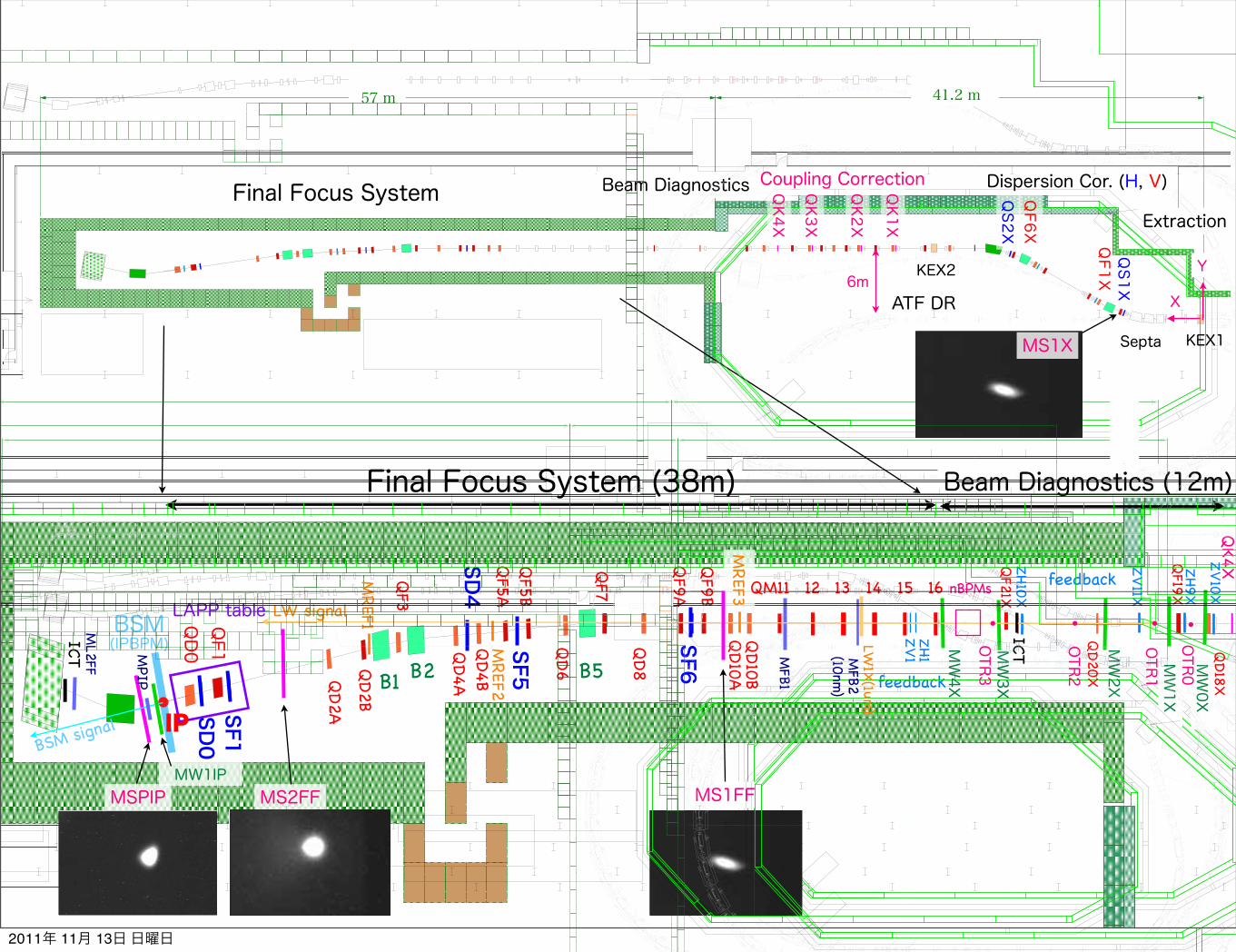
Final Focus System (38m) Beam Diagnostics (12m)
Beam DiagnosticsFinal Focus SystemExtraction
MS1FFMS2FF
!"#$%&
!"#$%&'()%&'
*+
,-."&/(0%&"123"&4$536
'(()*+,-*('#./01-%&%2,3#454
671,-,&81
##9:-
;<=17>=&?
5@A0
5@A0
5@A0
6::7=&?#",8=7=B=1C
#9:-#D,2E=&?#!=&?
;<%BB1-
F)((( GHH)I/G'
ATF2 Commissioning started in October 2008
MS1XMS1FFMS2FFMSPIP
First Signals Seen by 4 Screen Monitors, i.e. Beam reached to dump
KEX2
ZV6X
ZH3X
ZH4X
ZV7X
ZH5X
ZV8X
ZH6X
ZH7X
ZV9X
ZH8X
ZV10
X
ZH9X
ZV11
X
ZH10
X
MW3X
MW2X
ICT1
X
MW1X
MW0X
MW4X
ZV5X
ZV4X
ZH2X
ZV3X
ZH1X
ZV2X
ZV1X
QS1
XQF1
XBH
1X(ZX1
X)QD2
XMQD2
XQF3
X
QF4
XQD5
X
MQF3
XMQF4
XMQD5
X
BH2X
(ZX2
X)QF6
XQS2
X
BH3X
(ZX3
X)
QF7
X
QD8
X
QF9
X
MQF7
X
MQF8
X
QD1
0XQK1
X
QF1
1X
QD1
2XQK2
X
QF1
3X
QD1
4X
QF1
5XQD1
6XQK3
X
QF1
7X
QK4
X
QD1
8X
QD1
9X
QD2
0X
QD2
1X
MQF9
X
MQF1
3X
MQD1
4X
V1SF5
16
SD4
B5B2B1
QD0
QF1
H1
QM11 12 13 14 15
QD10B
QD10A
QF9B
QF9A
QD8
QF7
QD6
QF5B
QF5A
QD4B
QD4A
QF3
QD2B
QD2A
MB2
X
MB1
XBP
M20
ZH10
1R
ZH10
0R
QM7R
1
QM6R
1
KEX1
BS3X
BS2X
(ZS1
X)
BS1X
SF6
2008[42]
Su M Tu W Th F Sa Su M Tu W Th F Sa Su M Tu W Th F Sa Su M Tu W Th F Sa Su M Tu W Th F Sa Su M
January 2008 1 2 3 4 5 6 7 8 9 10 11 12 13 14 15 16 17 18 19 20 21 22 23 24 25 26 27 28 29 30 31
February 2008 1 2 3 4 5 6 7 8 9 10 11 12 13 14 15 16 17 18 19 20 21 22 23 24 25 26 27 28 29
March 2008 1 2 3 4 5 6 7 8 9 10 11 12 13 14 15 16 17 18 19 20 21 22 23 24 25 26 27 28 29 30 31
April 2008 1 2 3 4 5 6 7 8 9 10 11 12 13 14 15 16 17 18 19 20 21 22 23 24 25 26 27 28 29 30
May 2008 1 2 3 4 5 6 7 8 9 10 11 12 13 14 15 16 17 18 19 20 21 22 23 24 25 26 27 28 29 30 31
June 2008 1 2 3 4 5 6 7 8 9 10 11 12 13 14 15 16 17 18 19 20 21 22 23 24 25 26 27 28 29 30
July 2008 1 2 3 4 5 6 7 8 9 10 11 12 13 14 15 16 17 18 19 20 21 22 23 24 25 26 27 28 29 30 31
August 2008 1 2 3 4 5 6 7 8 9 10 11 12 13 14 15 16 17 18 19 20 21 22 23 24 25 26 27 28 29 30 31
September 2008 1 2 3 4 5 6 7 8 9 10 11 12 13 14 15 16 17 18 19 20 21 22 23 24 25 26 27 28 29 30
October 2008 1 2 3 4 5 6 7 8 9 10 11 12 13 14 15 16 17 18 19 20 21 22 23 24 25 26 27 28 29 30 31
November 2008 1 2 3 4 5 6 7 8 9 10 11 12 13 14 15 16 17 18 19 20 21 22 23 24 25 26 27 28 29 30 ATF Operation
ATF Operation start up
RF gun, linac, injection, DR Hardware commissioning
Radiation Inspection (RI)
commissioning for RI
December 2008 1 2 3 4 5 6 7 8 9 10 11 12 13 14 15 16 17 18 19 20 21 22 23 24 25 26 27 28 29 30 31
ATF Operation
High Beta operation
www.vertex42.com/calendars © 2008 Vertex42.com
Annual Calendar
startup from electron source to DR
commissioning for RI (Radiation Inspection)
2010年 2月 18日 木曜日
MS1X
!"#$%&'()%&'
*+
,-."&/(0%&"123"&4$536
ATF2 Commissioning started in October 2008
MS1XMS1FFMS2FFMSPIP
First Signals Seen by 4 Screen Monitors, i.e. Beam reached to dump
KEX2
ZV6X
ZH3X
ZH4X
ZV7X
ZH5X
ZV8X
ZH6X
ZH7X
ZV9X
ZH8X
ZV10
X
ZH9X
ZV11
X
ZH10
X
MW3X
MW2X
ICT1
X
MW1X
MW0X
MW4X
ZV5X
ZV4X
ZH2X
ZV3X
ZH1X
ZV2X
ZV1X
QS1
XQF1
XBH
1X(ZX1
X)QD2
XMQD2
XQF3
X
QF4
XQD5
X
MQF3
XMQF4
XMQD5
X
BH2X
(ZX2
X)QF6
XQS2
X
BH3X
(ZX3
X)
QF7
X
QD8
X
QF9
X
MQF7
X
MQF8
X
QD1
0XQK1
X
QF1
1X
QD1
2XQK2
X
QF1
3X
QD1
4X
QF1
5XQD1
6XQK3
X
QF1
7X
QK4
X
QD1
8X
QD1
9X
QD2
0X
QD2
1X
MQF9
X
MQF1
3X
MQD1
4X
V1SF5
16
SD4
B5B2B1
QD0
QF1
H1
QM11 12 13 14 15
QD10B
QD10A
QF9B
QF9A
QD8
QF7
QD6
QF5B
QF5A
QD4B
QD4A
QF3
QD2B
QD2A
MB2
X
MB1
XBP
M20
ZH10
1R
ZH10
0R
QM7R
1
QM6R
1
KEX1
BS3X
BS2X
(ZS1
X)
BS1X
SF6
2008[42]
Su M Tu W Th F Sa Su M Tu W Th F Sa Su M Tu W Th F Sa Su M Tu W Th F Sa Su M Tu W Th F Sa Su M
January 2008 1 2 3 4 5 6 7 8 9 10 11 12 13 14 15 16 17 18 19 20 21 22 23 24 25 26 27 28 29 30 31
February 2008 1 2 3 4 5 6 7 8 9 10 11 12 13 14 15 16 17 18 19 20 21 22 23 24 25 26 27 28 29
March 2008 1 2 3 4 5 6 7 8 9 10 11 12 13 14 15 16 17 18 19 20 21 22 23 24 25 26 27 28 29 30 31
April 2008 1 2 3 4 5 6 7 8 9 10 11 12 13 14 15 16 17 18 19 20 21 22 23 24 25 26 27 28 29 30
May 2008 1 2 3 4 5 6 7 8 9 10 11 12 13 14 15 16 17 18 19 20 21 22 23 24 25 26 27 28 29 30 31
June 2008 1 2 3 4 5 6 7 8 9 10 11 12 13 14 15 16 17 18 19 20 21 22 23 24 25 26 27 28 29 30
July 2008 1 2 3 4 5 6 7 8 9 10 11 12 13 14 15 16 17 18 19 20 21 22 23 24 25 26 27 28 29 30 31
August 2008 1 2 3 4 5 6 7 8 9 10 11 12 13 14 15 16 17 18 19 20 21 22 23 24 25 26 27 28 29 30 31
September 2008 1 2 3 4 5 6 7 8 9 10 11 12 13 14 15 16 17 18 19 20 21 22 23 24 25 26 27 28 29 30
October 2008 1 2 3 4 5 6 7 8 9 10 11 12 13 14 15 16 17 18 19 20 21 22 23 24 25 26 27 28 29 30 31
November 2008 1 2 3 4 5 6 7 8 9 10 11 12 13 14 15 16 17 18 19 20 21 22 23 24 25 26 27 28 29 30 ATF Operation
ATF Operation start up
RF gun, linac, injection, DR Hardware commissioning
Radiation Inspection (RI)
commissioning for RI
December 2008 1 2 3 4 5 6 7 8 9 10 11 12 13 14 15 16 17 18 19 20 21 22 23 24 25 26 27 28 29 30 31
ATF Operation
High Beta operation
www.vertex42.com/calendars © 2008 Vertex42.com
Annual Calendar
startup from electron source to DR
commissioning for RI (Radiation Inspection)
2010年 2月 18日 木曜日
MSPIP
!"#$%&
!"#$%&'()%&'
*+
,-."&/(0%&"123"&4$536
'(()*+,-*('#./01-%&%2,3#454
671,-,&81
##9:-
;<=17>=&?
5@A0
5@A0
5@A0
6::7=&?#",8=7=B=1C
#9:-#D,2E=&?#!=&?
;<%BB1-
F)((( GHH)I/G'
ATF2 Commissioning started in October 2008
MS1XMS1FFMS2FFMSPIP
First Signals Seen by 4 Screen Monitors, i.e. Beam reached to dump
KEX2
ZV6X
ZH3X
ZH4X
ZV7X
ZH5X
ZV8X
ZH6X
ZH7X
ZV9X
ZH8X
ZV10
X
ZH9X
ZV11
X
ZH10
X
MW3X
MW2X
ICT1
X
MW1X
MW0X
MW4X
ZV5X
ZV4X
ZH2X
ZV3X
ZH1X
ZV2X
ZV1X
QS1
XQF1
XBH
1X(ZX1
X)QD2
XMQD2
XQF3
X
QF4
XQD5
X
MQF3
XMQF4
XMQD5
X
BH2X
(ZX2
X)QF6
XQS2
X
BH3X
(ZX3
X)
QF7
X
QD8
X
QF9
X
MQF7
X
MQF8
X
QD1
0XQK1
X
QF1
1X
QD1
2XQK2
X
QF1
3X
QD1
4X
QF1
5XQD1
6XQK3
X
QF1
7X
QK4
X
QD1
8X
QD1
9X
QD2
0X
QD2
1X
MQF9
X
MQF1
3X
MQD1
4X
V1SF5
16
SD4
B5B2B1
QD0
QF1
H1
QM11 12 13 14 15
QD10B
QD10A
QF9B
QF9A
QD8
QF7
QD6
QF5B
QF5A
QD4B
QD4A
QF3
QD2B
QD2A
MB2
X
MB1
XBP
M20
ZH10
1R
ZH10
0R
QM7R
1
QM6R
1
KEX1
BS3X
BS2X
(ZS1
X)
BS1X
SF6
2008[42]
Su M Tu W Th F Sa Su M Tu W Th F Sa Su M Tu W Th F Sa Su M Tu W Th F Sa Su M Tu W Th F Sa Su M
January 2008 1 2 3 4 5 6 7 8 9 10 11 12 13 14 15 16 17 18 19 20 21 22 23 24 25 26 27 28 29 30 31
February 2008 1 2 3 4 5 6 7 8 9 10 11 12 13 14 15 16 17 18 19 20 21 22 23 24 25 26 27 28 29
March 2008 1 2 3 4 5 6 7 8 9 10 11 12 13 14 15 16 17 18 19 20 21 22 23 24 25 26 27 28 29 30 31
April 2008 1 2 3 4 5 6 7 8 9 10 11 12 13 14 15 16 17 18 19 20 21 22 23 24 25 26 27 28 29 30
May 2008 1 2 3 4 5 6 7 8 9 10 11 12 13 14 15 16 17 18 19 20 21 22 23 24 25 26 27 28 29 30 31
June 2008 1 2 3 4 5 6 7 8 9 10 11 12 13 14 15 16 17 18 19 20 21 22 23 24 25 26 27 28 29 30
July 2008 1 2 3 4 5 6 7 8 9 10 11 12 13 14 15 16 17 18 19 20 21 22 23 24 25 26 27 28 29 30 31
August 2008 1 2 3 4 5 6 7 8 9 10 11 12 13 14 15 16 17 18 19 20 21 22 23 24 25 26 27 28 29 30 31
September 2008 1 2 3 4 5 6 7 8 9 10 11 12 13 14 15 16 17 18 19 20 21 22 23 24 25 26 27 28 29 30
October 2008 1 2 3 4 5 6 7 8 9 10 11 12 13 14 15 16 17 18 19 20 21 22 23 24 25 26 27 28 29 30 31
November 2008 1 2 3 4 5 6 7 8 9 10 11 12 13 14 15 16 17 18 19 20 21 22 23 24 25 26 27 28 29 30 ATF Operation
ATF Operation start up
RF gun, linac, injection, DR Hardware commissioning
Radiation Inspection (RI)
commissioning for RI
December 2008 1 2 3 4 5 6 7 8 9 10 11 12 13 14 15 16 17 18 19 20 21 22 23 24 25 26 27 28 29 30 31
ATF Operation
High Beta operation
www.vertex42.com/calendars © 2008 Vertex42.com
Annual Calendar
startup from electron source to DR
commissioning for RI (Radiation Inspection)
2010年 2月 18日 木曜日
QK1X
QK2X
QK3X
QK4X
QS2X
Dispersion Cor. (H, V)Coupling Correction
57 m 41.2 m
KEX2
KEX1Septa
ZV10X
QD18X
MREF3 QM11
LW1X(1um
)
MW1IP
MPIP
QF6X
QF1X6m
Y
XATF DR
OTR3
OTR2
OTR1
OTR0
2011年 11月 13日 日曜日
11
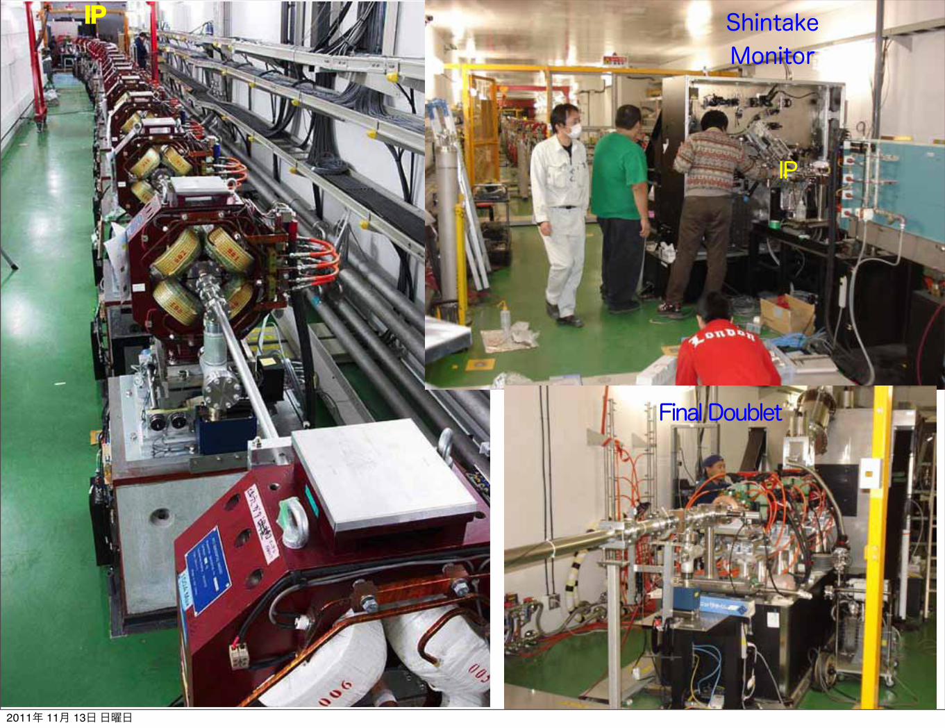
Shintake Monitor
IP
Final Doublet
IP
2011年 11月 13日 日曜日

IP region seeing from the downstream
IP carbon wires and IPBPMs in the IP chamber
2011年 11月 13日 日曜日
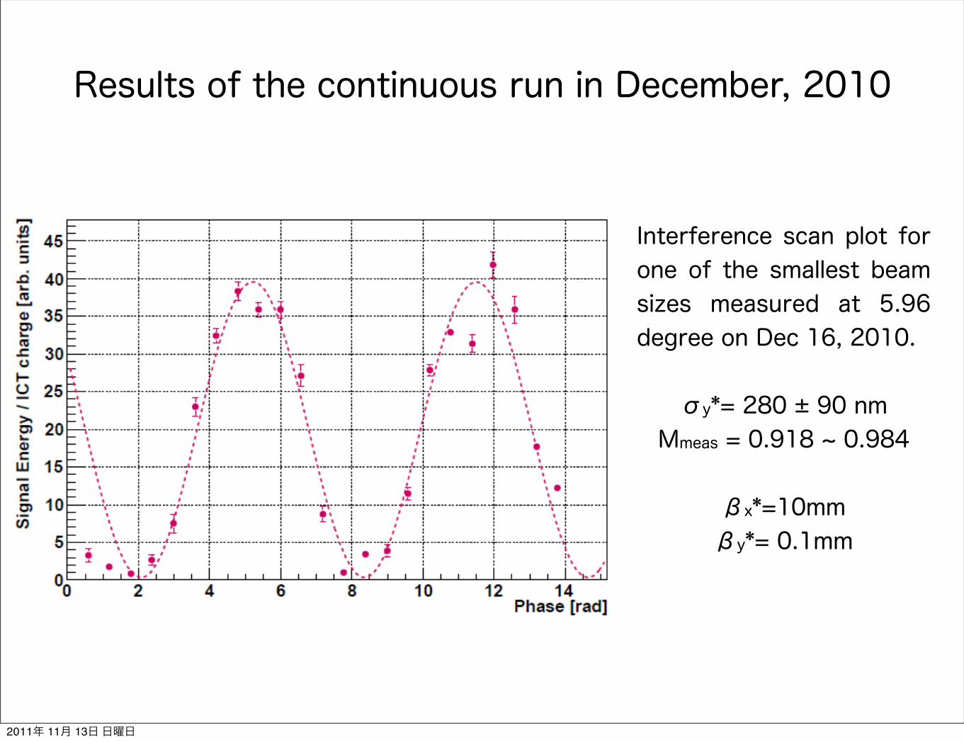
Interference scan plot for one of the smallest beam sizes measured at 5.96 degree on Dec 16, 2010.
σy*= 280 ± 90 nmMmeas = 0.918 ~ 0.984
βx*=10mmβy*= 0.1mm
Results of the continuous run in December, 2010
2011年 11月 13日 日曜日

FD/IP shield works
N. Terunuma, ATF2 weekly Meeting,11 May 20112011年 11月 13日 日曜日
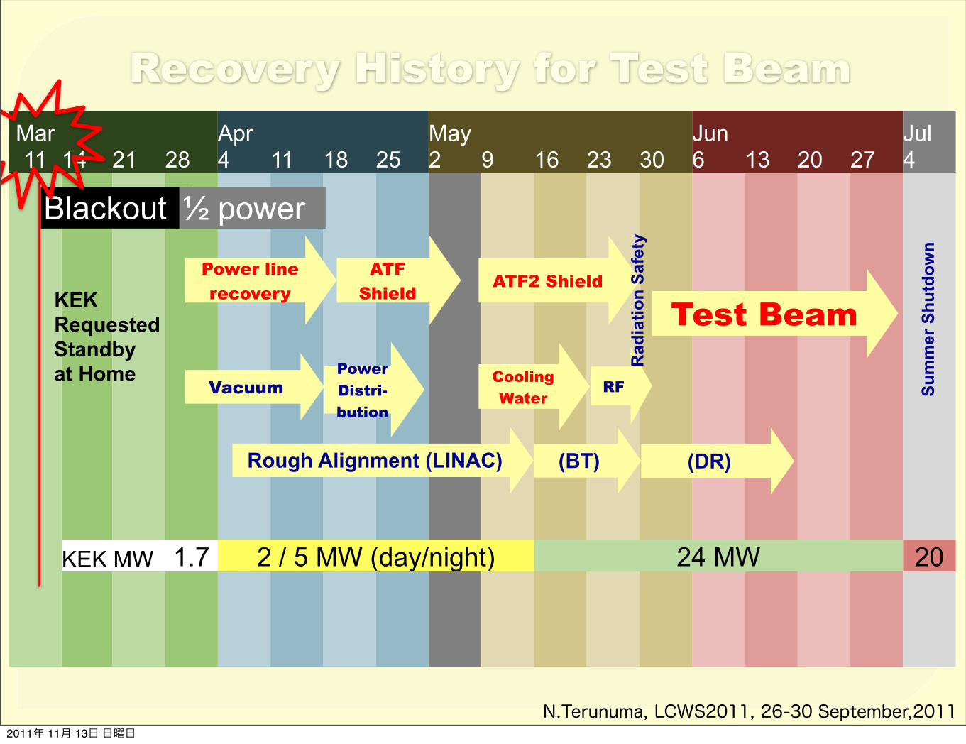
Recovery History for Test BeamMar11 14 21 28
Apr4 11 18 25
May2 9 16 23 30
Jun6 13 20 27
Jul4
KEK MWKEK MW 1.7 2 / 5 MW (day/night)2 / 5 MW (day/night)2 / 5 MW (day/night)2 / 5 MW (day/night)2 / 5 MW (day/night)2 / 5 MW (day/night) 24 MW24 MW24 MW24 MW24 MW24 MW24 MW 20
Power line recovery
Rough Alignment (LINAC)
RF
Blackout ½ power
Vacuum
ATF2 Shield
Cooling Water
(BT) (DR)
Sum
mer
Shu
tdow
n
Test BeamKEKRequested Standbyat Home Power
Distri-bution
ATF Shield
Rad
iatio
n Sa
fety
N.Terunuma, LCWS2011, 26-30 September,20112011年 11月 13日 日曜日

Stored beam in DR (x1010 e/bunch)A stored beam was delivered to the dump of ATF2.No cri'cal damage on the accelerator was found.
6/1 6/3 6/8 6/10 6/13 6/17 6/24 6/30
0.5x10¹⁰
1.0x10103 trains
XSR ready
Compton2‐mirror
FONT
3 trains
Cavity BPMsFFTB moverHAPS
Freq. Adjust
V‐emi8ance (XSR) ~30pm
DR rough alignment for checkout was con'nued in day'me.
InspecUo
n of th
e radiaU
on safety
N.Terunuma, LCWS2011, 26-30 September,20112011年 11月 13日 日曜日

Alignment: DR levelaligned in June, aligned in summer
VerUcal (mm)
‐0.5
0.0
‐1.0
0.5
North West Arc South
East Arc is under realignment.
Target: |x|< 90 um
N.Terunuma, LCWS2011, 26-30 September,20112011年 11月 13日 日曜日

WaiUng for alignment: ATF2
Floor of ATF2 sank about 1.5 mm.
Level of the EXT‐ATF2 magnets
EXT FF
VerUcal (Z, m
m)
QD0 mover is OFF
QF1 mover is ON
FFTB movers are “zero” posiUon.
Target: +‐0.1 mm
‐1.0
0.0
‐2.0
‐3.0
N.Terunuma, LCWS2011, 26-30 September,20112011年 11月 13日 日曜日

(WaiUng for) alignment: ATF2
Horizontal (Y)
EXT FF
Target: +‐0.1 mm
‐1.0
0.0
‐2.0
‐3.0
0.0
‐1.0
‐2.0
‐3.0
‐4.0
1.0(mm)(mm) Longitudinal (X)
EXT FF
Datum on floor
We are checking the definiUon of the datum on the floor used at the ATF2 construcUon. Offset?
N.Terunuma, LCWS2011, 26-30 September,20112011年 11月 13日 日曜日

OpUcal Matching RouUnes in LucreUa• New solware wrimen in LucreUa, a “Match” class for first and higher‐order beam matrix matching using tracking engine, fast 3rd‐order polynomial finng to IP beam parUcles and Matlab‐based opUmisaUon rouUnes.– ‘lsqnonlin’ for first‐order (Twiss) parameter matching
• This produces a “first‐pass” soluUon with the desired opUcal parameters but with exisUng 2nd and 3rd order geometric and chromo‐geometric aberraUons present at IP sUll.
– ‘fminsearch’ (Nelder‐Mead)• Remove higer‐order aberraUons by direct opUmisaUon of sigma_11 and sigma_33 terms
• Generate range of matched FFS lances with different IP beta funcUons.• Match constraints
– Waist at IP with given beta funcUons– Waists at MFB1FF and (MFB2FF OR LW1FF)
• Ensures correct phase advances for FFS feedbacks
• Match variables– Matching quads + final doublet for iniUal Twiss match– All FFS quadrupole and sextupole strengths plus SK1FF strength, for final beam size opUmisaUon.
G.White, LCWS2011, 26-30 September,2011
Deep understanding of the beam tuning
( IP vertical beta constrained : bcons )
2011年 11月 13日 日曜日
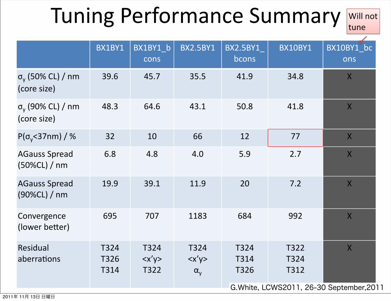
Tuning Performance SummaryBX1BY1 BX1BY1_b
consBX2.5BY1 BX2.5BY1_
bconsBX10BY1 BX10BY1_bc
ons
σy (50% CL) / nm (core size)
39.6 45.7 35.5 41.9 34.8 X
σy (90% CL) / nm (core size)
48.3 64.6 43.1 50.8 41.8 X
P(σy<37nm) / % 32 10 66 12 77 X
AGauss Spread (50%CL) / nm
6.8 4.8 4.0 5.9 2.7 X
AGauss Spread (90%CL) / nm
19.9 39.1 11.9 20 7.2 X
Convergence (lower bemer)
695 707 1183 684 992 X
Residual aberraUons
T324 T326 T314
T324<x’y>T322
T324<x’y>αy
T324T314T326
T322T324T312
X
Will nottune
G.White, LCWS2011, 26-30 September,20112011年 11月 13日 日曜日

BX10BY1 Tuning Results
G.White, LCWS2011, 26-30 September,2011
by simulation
2011年 11月 13日 日曜日

December Data
• Following ~expected curve.
• EXCEPT:–<xy>–Do not expect this aberraUon term to appear from simulaUons.
– If corrected coupling at FFS entrance, nothing in FFS to introduce this (magneUcally)
G.White, LCWS2011, 26-30 September,20112011年 11月 13日 日曜日

Coupling AberraUon Induced at IP due to FFS Magnet Rolls and Offsets
G.White, LCWS2011, 26-30 September,20112011年 11月 13日 日曜日

Why do we see beam size improvement with applicaUon of <xy> knob?
• Alignment of IPBSM fringes with respect to FFS alignment frame?
– If plane of fringes rotated by ~20 mrad (~3.5 degrees), provides a similar contribuUon to beamsize in tuning simulaUons as that seen in experiment.
• IMPORTANT:
– If waist not centred on IPBSM exactly, <x’y> generates <xy>, therefore MUST FIRST REDUCE <x’y> AND αy TERMS BEFORE USING <xy> KNOB.
– It could be that in Dec we hadn’t fully removed <x’y> term and the waist was not exactly in place, and corrected <x’y> with <xy> knob.
• Having <xy> source and <x’y> source at IP greatly complicates tuning process, we should try to find and eliminate any <xy> sources manually first.
• Using a larger βx* op'cs also makes this problem worse.
• !‐‐‐ Probably essen'al to have roll control of IPBSM fringes ‐‐‐!
– @ ~100urad level (for 10um σx)
G.White, LCWS2011, 26-30 September,20112011年 11月 13日 日曜日

Schedule (draft for discussion)Sep.26
Oct.3 10 17 24 31
Nov.7 14 21 28
Dec.5 12 19 26
BeamBeam
DR
Checkout of beam instruments
EXT-FF
Low emittance,Compton and Others
ATFR&D
ATF2R&D
Alignment
DR survey
ATF2 &TBmeeting,or Jan.2012
Recovery of 10 pm (DR)
Recovery of 300 nm Goal-1 and others
extraction
survey survey
N.Terunuma, LCWS2011, 26-30 September,20112011年 11月 13日 日曜日
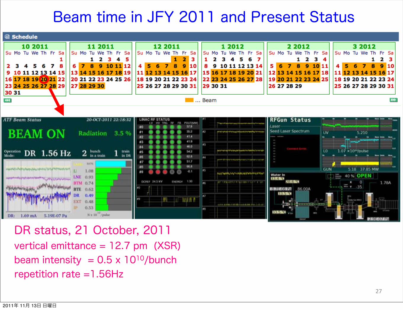
27
DR status, 21 October, 2011vertical emittance = 12.7 pm (XSR)beam intensity = 0.5 x 10¹⁰/bunchrepetition rate =1.56Hz
Beam time in JFY 2011 and Present Status
2011年 11月 13日 日曜日

27
DR status, 21 October, 2011vertical emittance = 12.7 pm (XSR)beam intensity = 0.5 x 10¹⁰/bunchrepetition rate =1.56Hz
Beam time in JFY 2011 and Present Status
> 1 x 10¹⁰/bunch12.8 pm (XSR)
vertical emittance at FF~ 20pm (OTR) w/o corrections
EXT-FF beam tuning, 8 Nov. 2011
2011年 11月 13日 日曜日

28
!"#"$%
&$'
()*+",-"./
012
()*+",-"./
012
3"4.
56789"
9:*
;<=
>?@
ABCDE
ABCCC
EFF D
DG
DDF DDC
DDF
HFH
GF ABCDF
DBDID
EAHJK
ADE
GAD
LC
ABE
6MNNOPQRMS
TURUVRMS
W51460
1398
5560
5900
IPBSM CsI
Collimator (movable)
56 x 26
4100
beam pipe
~1417
4440
2nd Collimator
QD0 QF1 Beam
IPBSM
γ-detector(IPBSM)
Last BendBeam dump
Installation of the 2nd Collimator inside of the last bend
3500
2nd collimator
background sourceat the beam pipe
2011年 11月 13日 日曜日

29
~ 4440
~ 3500
1398
Last Bend
26 15 20
γ detector of IPBSM (Cs I)
Pb Collimator
56
Background source point
3500 / 4440 x (13+10) - 10 = 8.1 mmso, aperture of 2nd collimator < 2 x 8.1 =16.2mm
Side View
56 40
2nd Collimator200 long SUS
Background source point
2011年 11月 13日 日曜日
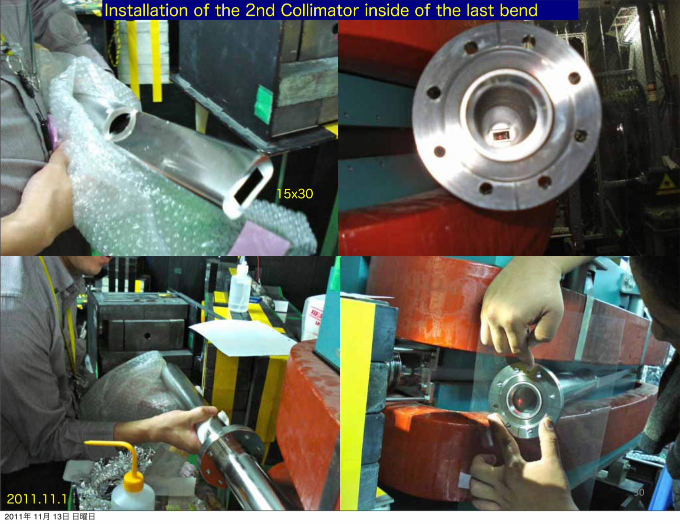
302011.11.1
Installation of the 2nd Collimator inside of the last bend
15x30
2011年 11月 13日 日曜日

LW scan in 10-11 November 2011
2 deg.
σ=13um
30 deg.
σ=15um
with “nominal” optics and S/N = 5~6
2 deg.
30 deg.
19.5mm
19.5mm
2011年 11月 13日 日曜日

Major issues1. Commissioning of the 30 degree mode at IPBSM good collaborate between beam tuning and Tokyo groups signal, i.e. laser focus is a key issue done background control is a key issue done
2. Choice of optics, i.e. β*x =1 cm and β*y =0.1 mm background in IPBSM - 2nd collimator in the chamber, installed jitters of incoming beam monitored by BPM system with IPBPMs
3. Vertical emittance growth in EXT DR to EXT ?, e.g. monitoring the orbit and re-producibility
4. Large coupling correction needed at IP rotation of IPBSM fringes ?
5. Effect of the Multipole components in the FF especially important for beam with σ*y < 100 nm mitigation by 2.5 times nominal horizontal beta function at IP
Alignment of optics system will be checked.
2011年 11月 13日 日曜日
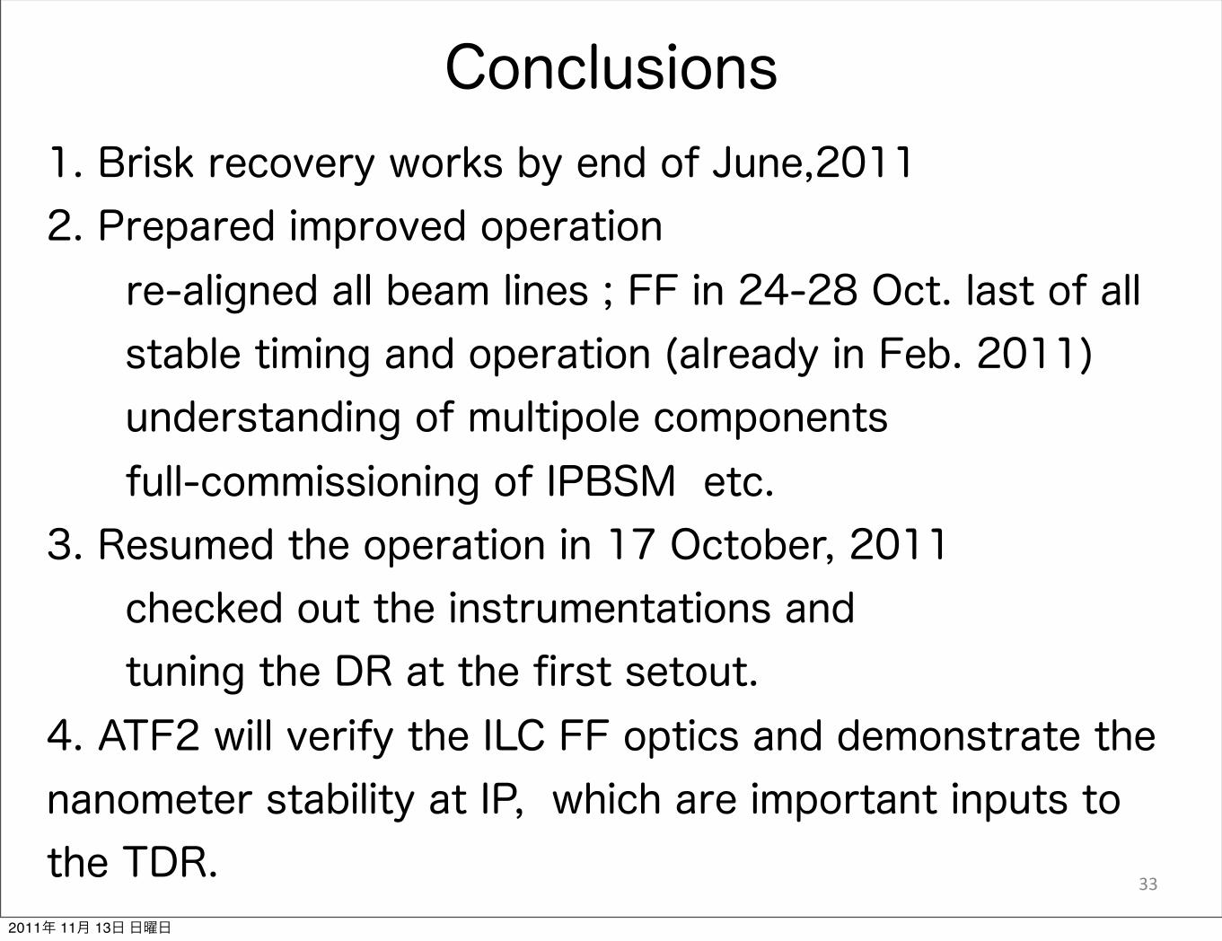
Conclusions
33
1. Brisk recovery works by end of June,20112. Prepared improved operation re-aligned all beam lines ; FF in 24-28 Oct. last of all stable timing and operation (already in Feb. 2011) understanding of multipole components full-commissioning of IPBSM etc.3. Resumed the operation in 17 October, 2011 checked out the instrumentations and tuning the DR at the first setout.4. ATF2 will verify the ILC FF optics and demonstrate the nanometer stability at IP, which are important inputs to the TDR.
2011年 11月 13日 日曜日