automatic access control and traffic management …
TRANSCRIPT

A PROJEKT AZ INTERREG CENTRAL EUROPE PROGRAMBÓL, AZ EURÓPAI REGIONÁLIS FEJLESZTÉSI ALAP
TÁMOGATÁSÁVAL, AZ EURÓPAI UNIÓ ÉS MAGYAR ÁLLAM TÁRSFINANSZÍROZÁSÁVAL VALÓSUL MEG.
ENGLISH SUMMARY -
AUTOMATIC ACCESS CONTROL AND
TRAFFIC MANAGEMENT SYSTEM PLAN
BUDAPEST FREEPORT LOGISTICS LTD.
Version 1
07 2019

A PROJEKT AZ INTERREG CENTRAL EUROPE PROGRAMBÓL, AZ EURÓPAI REGIONÁLIS FEJLESZTÉSI ALAP
TÁMOGATÁSÁVAL, AZ EURÓPAI UNIÓ ÉS MAGYAR ÁLLAM TÁRSFINANSZÍROZÁSÁVAL VALÓSUL MEG.
Table of contents
1. Introduction ....................................................................................... 1
1.1. Methodology ......................................................................................2
2. System requirements ............................................................................ 3
3. Access control ..................................................................................... 4
3.1. Operation of the access control system ......................................................4
3.1.1. Accessing BFL by using the app: .........................................................6
3.1.2. Accessing BFL by not using the app: .....................................................7
4. Traffic management ............................................................................. 9
5. Hardware.......................................................................................... 10
5.1. Barrier and camera system .................................................................. 10
5.2. WIFI .............................................................................................. 10
5.3. Kiosk ............................................................................................. 10
5.4. SMART displays ................................................................................. 12
6. Software........................................................................................... 13
6.1. Automatic license plate recognition system ............................................... 13
6.2. Database ........................................................................................ 13
6.3. Kiosk and communication .................................................................... 13
6.4. Navigation ...................................................................................... 13
6.5. Application ..................................................................................... 13
6.6. Web .............................................................................................. 14
6.7. SMART displays ................................................................................. 14
7. Pilot Action ....................................................................................... 15
8. Action plan (GANTT) ............................................................................ 16
Table of Images
1. Image - Territory of BFL and position of the gates ..............................................1 2. Image– Table of tasks related to the specification and its schedule ..........................2 3. Image– Current access control system installed at BFL by Digital Entry Sytem Control. ...4 4. Image– Input and data flow in the system ........................................................5 5. Image– App usage .....................................................................................6 6. Image– Entering to BFL without app usage .......................................................7 7. Image– Action plan of the new system development .......................................... 16

Project co-funded by the European Union.
1
1. Introduction
The Budapest Freeport Logistics Ltd. successfully applied for and won support in the Interreg CENTRAL
EUROPE CE-1278 CORCAP project.
This business specification excerpt summarizes the plan of the automatic access and traffic control
system (system) for road vehicles at Budapest Dock Freeport Logistics and Industry Park (BFL).
Environment of the system:
There are three gates in operation on the territory of BFL currently. The automatic access control
system will be implemented here.
1. Image - Territory of BFL and position of the gates
Source: https://goo.gl/maps/8LxvJR8cZGquyn3aA
• Gate North - (gate nr. 1, a new gate, which is not at its final location yet)
• Gate II. – (mainly for personal vehicles or small trucks)
• Gate South - (gate nr. 4 – 90% of all the lorries use this entrance and a scale is also located
here)
The system shell be planned for an estimated average traffic of 5000 vehicles daily in peak season.

Project co-funded by the European Union.
2
Barriers and cameras are already installed at the gates. Pictures are taken of the vehicles
automatically during entry and the images are saved. The system has a license plate recognition
feature, but its operation is instable yet. However, the recognized license plate number will be saved
as well if the recognition is successful. The barriers automatically open after a pre-set waiting time
with the support of sensors built in the road. There is no control of access in place, nor real use of
the saved license plate number information currently.
Traffic management to the tenants are not solved after the access on site. Due to lack of capacity
and space the creation of buffer area is planned.
Based on this plan, offline, online, artificial intelligence, sensors, cameras, cloud-based solutions and
mobile applications will all help to develop an automated control system that enables efficient
movement within the site of BFL. Proper vehicle management solves bottlenecks and provides a
greener, faster and more efficient service provider.
1.1. Methodology
Besides continuous discussions with BFL, on-site consultations, field visits, infrastructure surveys and
interviews with tenants took place 6 times during the nearly 60 days of preparation of the business
specification. The map data to be digitized (location, area, roads, building positions) were surveyed.
Pictures were taken and visualization made for the tasks to be carried out for the system development
and for the Pilot Action.
2. Image– Table of tasks related to the specification and its schedule
Source: RowanHill Digital Ltd.
3 10 17 24 1 8 15 22
Regular discussions (email, telefon)
Coordination
Personal meetings
Field work
Digitalisation survey
Interviews
TasksJune July

Project co-funded by the European Union.
3
2. System requirements
For the automated access of road vehicles, an automated access control system with cameras and
barriers is required. For the management of traffic on site BFL, a navigation application (app) needs
to be developed as well.
➢ The license plate numbers of road vehicles shall be automatically recognized and stored to a
central database upon arrival to gates.
o Automated recognition and storage of vehicle characteristics (truck or passenger car)
to a central database.
o Ability to identify and recognize logos, images, information placed on vehicles, and
linking its content to the tenant; to speed up the identification of the vehicles arriving
to a specific tenant.
➢ Input: Searching for and entering the tenant where the vehicle has arrived to. It should be
possible for the driver to be able to do this in a few seconds at an info point or via the app.
Assigning the input information to the license plate number(s) and store it to the central
database.
➢ The system shall notify the tenant about the arrival of a vehicle. The access rights of the
vehicle shall be validated in the system by the tenant.
➢ If a vehicle cannot gain access, the system should be able to handle it accordingly (e.g.: staff
alert, setting the vehicle aside)
➢ Based on the input, the system will plan a direct route for the vehicle to the tenant of BFL
with the application. (Navigation will happen via the app, info point - printing map with route
information)
➢ Vehicles that are identified via the access control and entered their destination, the system
shall be able to navigate them on site BFL with the support of Intelligent (SMART) displays.
➢ Directing to buffer parking. Vehicles should be directed there if waiting for loading at the
address requires this. Tenants or the system shall be able to call the waiting vehicle from the
buffer as soon as capacity has freed up.
➢ Possibility to report status of the number of vehicles on site BFL, how many are in buffer,
etc. The movement of vehicles on site should also be traceable for traffic management and
safety purposes.
➢ The system should be able to provide data to the Integrated Port Information System (KIR),
which is currently under development.
➢ The system shall be modularly scalable, especially ready for the connectivity to the electronic
enterprise resource planning systems of the tenants. (Possibility to connect via web interface)
Project co-funded by the European Union.
4
3. Access control
Informing the vehicles about the system to be used on site BFL begins well before entry. (Official
communication channels, website, information boards, etc.)
Usage of the system may begin with the app well before arriving to gates. However, the first time a
vehicle arrives to BFL, it will be informed about the possibility of using an app or an info point.
Controlled entry requires license plate number recognition and input for destination. The registration
of the license plate number is automatic, and the destination is assigned to the database by the
system, based on the input provided through either at the info point or by the app.
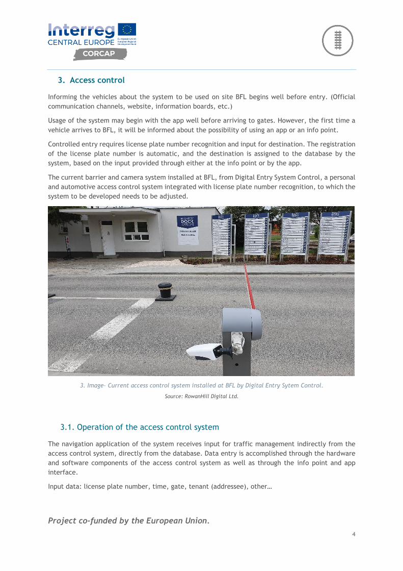
The current barrier and camera system installed at BFL, from Digital Entry System Control, a personal
and automotive access control system integrated with license plate number recognition, to which the
system to be developed needs to be adjusted.
3. Image– Current access control system installed at BFL by Digital Entry Sytem Control.
Source: RowanHill Digital Ltd.
3.1. Operation of the access control system
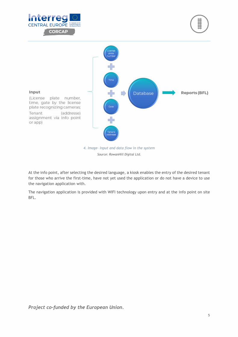
The navigation application of the system receives input for traffic management indirectly from the
access control system, directly from the database. Data entry is accomplished through the hardware
and software components of the access control system as well as through the info point and app
interface.
Input data: license plate number, time, gate, tenant (addressee), other…
Project co-funded by the European Union.
5
4. Image– Input and data flow in the system
Source: RowanHill Digital Ltd.
At the info point, after selecting the desired language, a kiosk enables the entry of the desired tenant
for those who arrive the first-time, have not yet used the application or do not have a device to use
the navigation application with.
The navigation application is provided with WIFI technology upon entry and at the info point on site
BFL.

Project co-funded by the European Union.
6
3.1.1. Accessing BFL by using the app:
5. Image– App usage
Source: RowanHill Digital Ltd.
App users can provide input to the system by entering/choosing their license plate number(s).
For returning vehicles, if the vehicle with which the user arrives changes, it is possible to enter
multiple license plates; it is always an option to select the current license plate number or enter a
new one.
By selecting the tenant, the app will navigate on the planned route.
Upon entry, the license plate recognition system updates the database with the inputs from the
application based on the license plate number and manages the SMART displays according to the route
plan.
Project co-funded by the European Union.
7
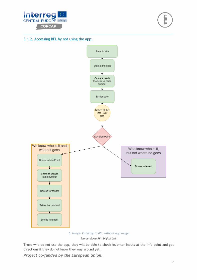
3.1.2. Accessing BFL by not using the app:
6. Image– Entering to BFL without app usage
Source: RowanHill Digital Ltd.
Those who do not use the app, they will be able to check in/enter inputs at the info point and get
directions if they do not know they way around yet.

Project co-funded by the European Union.
8
The input can be provided for the system by entering the license plate number and tenant/addressee
at the Info point.
The driver will get a printed direction from the kiosk after entering the tenant. With the planned
route, he can navigate to the desired tenant.
The system updates the inputs with the license plate number stored in the database upon entering
the site at the gate and manages the SMART displays according to the route plan.
Those who knows where to go and does not enter input either through the app or the info point, the
system will not be able to provide data about that, only the information of entry and exit of the given
license plate number.

Project co-funded by the European Union.
9
4. Traffic management
Once entered to the site, the system can navigate the vehicle to the tenant or buffer parking along a
route based on the inputs of the database, using the app, or a printed map, supported by SMART
displays and cameras.
The system assigns the address and route to the license plate number in the database, which is
supported by SMART displays and the cameras on the displays when the vehicle arrives to them,
showing the correct direction based on license plate number recognition.
For users of the app, they smart devices navigate to tenants directly.
For users of the printed map, smart displays at the junctions will help and the vehicle will be able to
follow the markings of the buildings to the tenants; with the support of building signs with road
painting.
Project co-funded by the European Union.
10
5. Hardware
Hardware requirements of the system:
5.1. Barrier and camera system
License plate recognizing cameras: PARK-IT (ARH) cameras.
The automatic barriers are Dítec QIK Barriers:
“The high performance and high flexibility of the model make it suitable for the task at BFL. QIK is
the ideal solution for monitoring safe passage in medium to high traffic environments.”
(Source: https://www.ditec.hu/automatske-rampe/)
5.2. WIFI
Free, limited, high-bandwidth Wi-Fi technology must be provided with the most appropriate devices
at the gates and info point (4 pcs) for downloading the application.
5.3. Kiosk
The basic parameters of the device that provides solution for data entry and information at the info
point:
Outdoor system
Point-Multipoint central transmitter Specification Value
Radio: Rocket PRISM AC
Antenna: Sector antenna
Transmitting mode: 5GHz TDMA PtMPt
Network mode: Bridge
Power: PoE Switch and UPS
Router device: EdgePoint R6
Point-Multipoint client receiver Specification Value
Radio: NanoBeam vagy NanoStation AC
Antenna: built in
Transmitting mode: 5GHz TDMA PtMPt
Network mode: Bridge
Power: PoE sender, optional UPS
Network tipology: direct connection with table or kiosk

Project co-funded by the European Union.
11
Screen requirements:
• Resolution at least: 768X1366(HD Ready)
• Touch: Multi capacity
• Technology: TFT LCD
• Colour set: 16 million
• Brightness at least: 200 nits
Required water and dust resistance standard:
• IP68(total water and dust resistance)
Operation system:
• Windows
Power supply:
• DC 12V 100-240V V @50/60Hz
Required accessory:
• Thermal printer with cutter
Access and information kiosk
Application Outdoor
Material Painted steel
Color Based on demand
Display 21" Multitouch touch screen
Speakers Integrated
Camera Integrated IP cameras
Keyboard Vandal-proof outdoor metal keyboard with 101 buttons
Printer Integrated outdoor industrial thermal printer
Control Integrated Kiosk
RAM 4GB
Lan 10/100 Ethernet
Operation system Windows7
Applicatoin software Ykiosk Lite Secure Browser
Size 2100x630x250mm
Project co-funded by the European Union.
12
Communication standards, optionally containing at least 1:
• LAN
• WIFI
• 3G
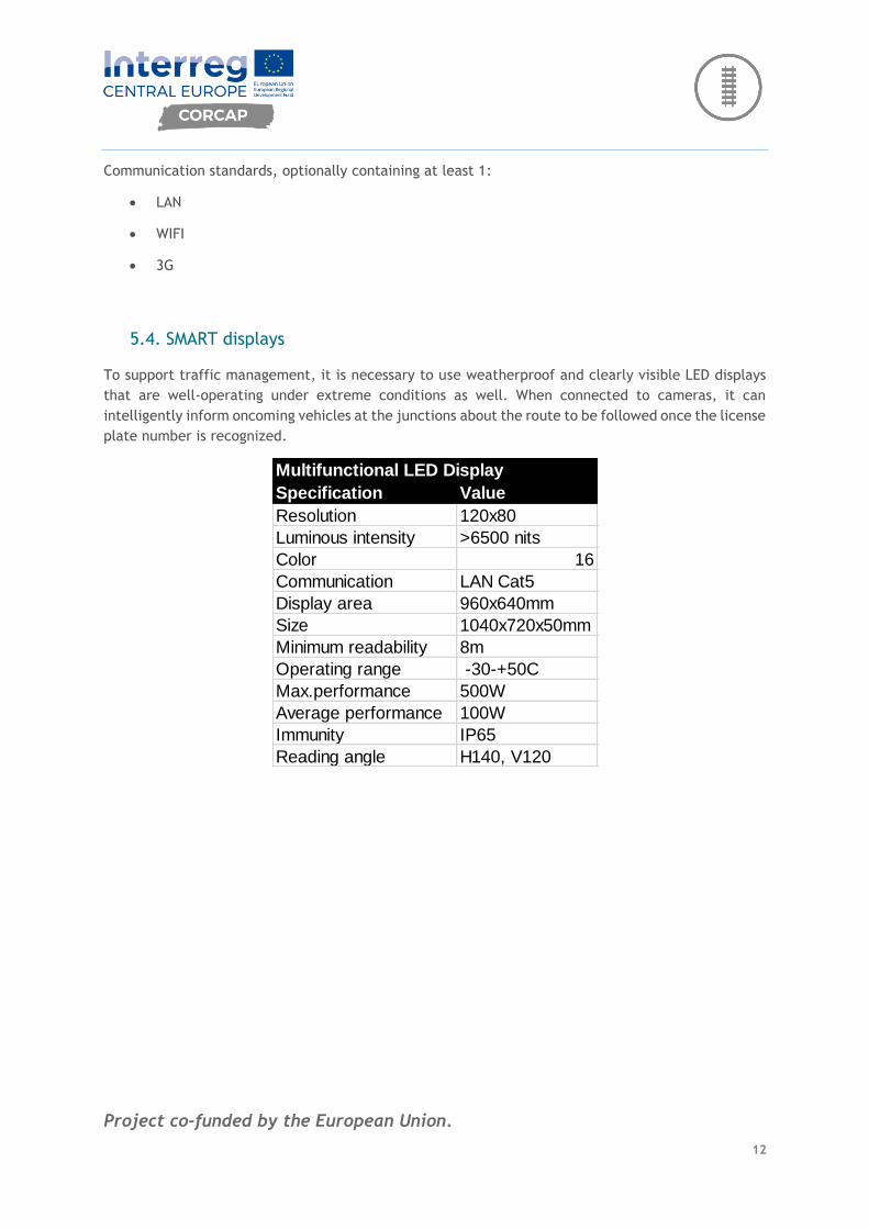
5.4. SMART displays
To support traffic management, it is necessary to use weatherproof and clearly visible LED displays
that are well-operating under extreme conditions as well. When connected to cameras, it can
intelligently inform oncoming vehicles at the junctions about the route to be followed once the license
plate number is recognized.
Specification Value
Resolution 120x80
Luminous intensity >6500 nits
Color 16
Communication LAN Cat5
Display area 960x640mm
Size 1040x720x50mm
Minimum readability 8m
Operating range -30-+50C
Max.performance 500W
Average performance 100W
Immunity IP65
Reading angle H140, V120
Multifunctional LED Display

Project co-funded by the European Union.
13
6. Software
6.1. Automatic license plate recognition system
Producer and distributor of controllers and access control software:
DigitalEye IT Ltd.
The software is developed by DigitalEye with ARH license plate recognition. (ARH is the manufacturer
of speed cameras and vignette control cameras used on public roads).
6.2. Database
Microsoft MSSQL 18
Microsoft's relational database is recommended as the basis for the database. Considering the
technologies used, the Microsoft SQL database engine is able to guarantee optimum performance
while maximizing the technical solutions required.
6.3. Kiosk and communication
.NET core
Communication between the core system and a Kiosk can take place through an API layer. The task
of this layer is to combine the data transmitted by the Kiosk with the data received from the license
plate recognition system and to write it to the database of the core system.
The API layer is recommended to be made on C# basis and .NET core base system.
6.4. Navigation
➢ Google Maps
➢ Waze
➢ Point of Interest (POI)
The navigation software is based partly on locations that can be marked on Google Maps and partly
on POIs.
The two types of solution are needed because POIs are used in traditional satellite (GPS) navigation
solutions, whereas connected smart device solutions are mostly based on points marked on Google
Maps.
The app to be developed will launch navigation directly from the application using Google Maps or
Waze. Navigation can be used by users in a familiar environment but with BFL-specific content.
6.5. Application
Microsoft Xamarin
The application may be based on the language of Microsoft Xamarin. Xamarin is a cross-platform
development solution based on Microsoft's CLI infrastructure, often known as .NET. This Microsoft

Project co-funded by the European Union.
14
solution is built on language elements of C # but split into iOS and Android. Each branch is similar to
native solutions, but with C # features.
6.6. Web
➢ HTML5
➢ Ajax
➢ Jqery
➢ CSS3
Web content development can be based on HTML5, CSS and javascript technologies. Responsiveness
must be the main consideration when choosing technologies.
6.7. SMART displays
.NET core
Communication with SMART displays can be implemented by the API layer mentioned above. The API
layer is responsible for addressing the smart table controller and passing the data to it in the proper
form.
Triggers and automations running in the database layer are also responsible for the functionality of
the layer.
The API layer can be made in .NET core framework. Semantically, it is recommended to use the
language of C#.
Project co-funded by the European Union.
15
7. Pilot Action
The automated access control and traffic management system to be implemented at the BFL, will be
developed based on this business specification, but it will be validated in a Pilot Action first.
The system and integrated tools developed during the Pilot Action, as well as the lessons learned from
the processes implemented, experiences at the gate, and the impacts of these on the life of BFL will
all be recorded.
Pilot Action will be documented, which will allow other logistics centres in the corridor to adopt and
apply well-developed solutions developed at BFL.
The specific tools and technology included in the plan are primarily a recommendation and can be
replaced by the need for improvement and the lessons learned from the Pilot Action where necessary.
The system will be evaluated according to the methodological requirements that will be developed
in WPT2. The effects of the system will be evaluated against what was planned, lessons learned during
implementation, and success factors for deliverability will be identified.
The pilot action will be documented, and experience will be shared with other target groups and
international partners.
If any error occurs during the Pilot Action (e.g. info point is in the wrong place, the confirmation
process needs to be modified) it will be corrected before it is implemented by any partner or other
logistics centre.

Project co-funded by the European Union.
16
8. Action plan (GANTT)
7. Image– Action plan of the new system development
Source: RowanHill Digital Ltd.