avr microcontrollers and ir sensors - · pdf file٢٠٠۵ m.ghadiry sample controller circuit...
TRANSCRIPT
٢٠٠۵ M.Ghadiry
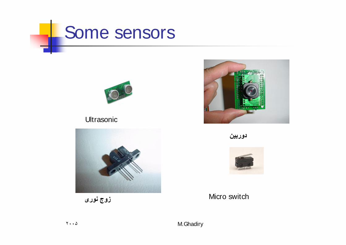
Some sensors
دوربين
Ultrasonic
زوج نوری Micro switch
٢٠٠۵ M.Ghadiry
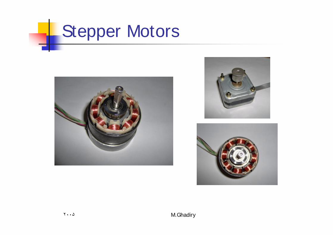
Stepper Motors
٢٠٠۵ M.Ghadiry
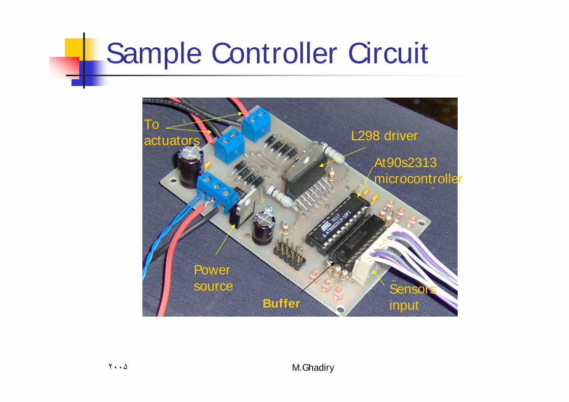
Sample Controller Circuit
BufferSensors input
Power source
At90s2313 microcontroller
L298 driverTo actuators
٢٠٠۵ M.Ghadiry
What is GND and VCC?
GND :The Base for indicating voltage Usually the negative pole of DC power source or battery .VCC ,VDD,VS : Positive pole of DC Power source or battery .Usually we indicate +5v with VCC and other voltages with VS and VDD.
٢٠٠۵ M.Ghadiry
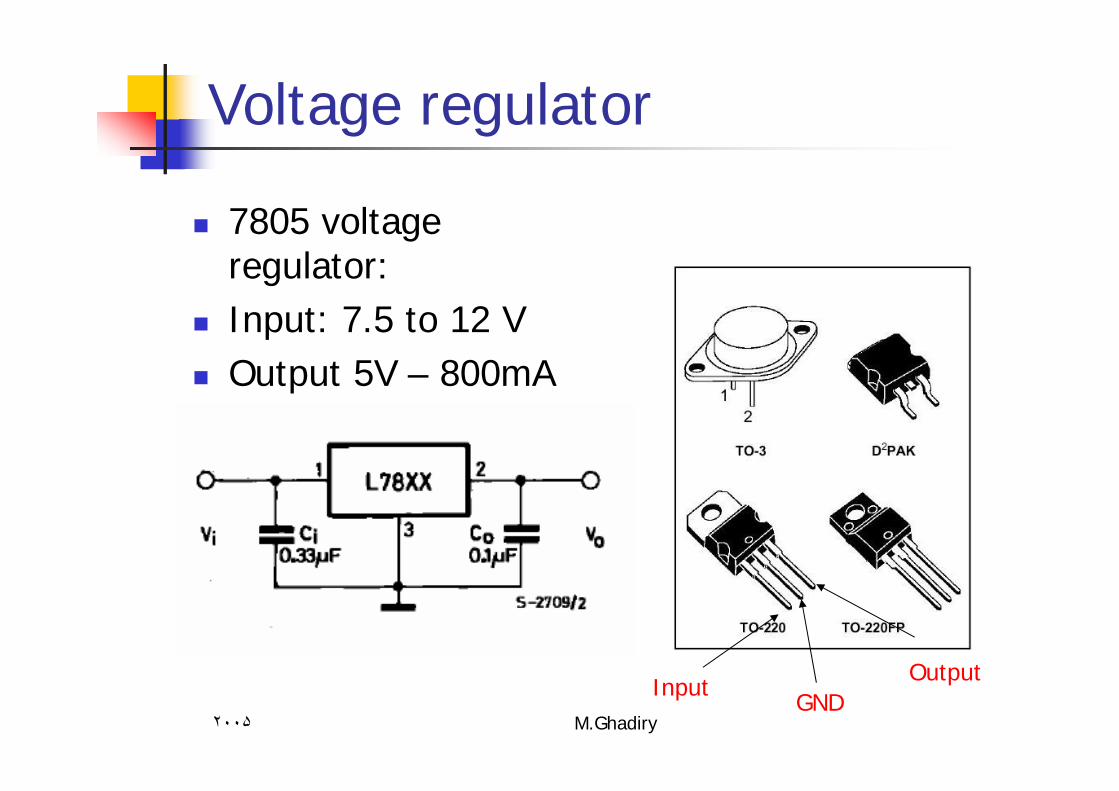
Voltage regulator
7805 voltage regulator:Input: 7.5 to 12 VOutput 5V – 800mA
InputGND
Output
٢٠٠۵ M.Ghadiry
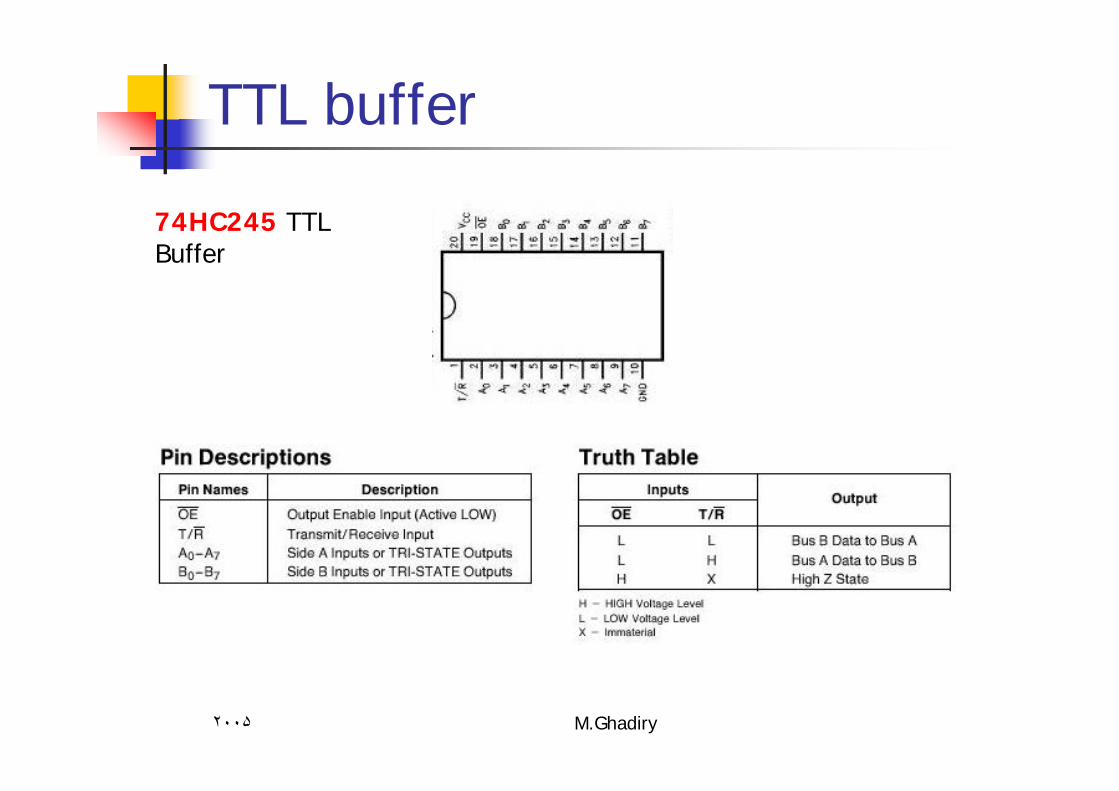
TTL buffer
74HC245 TTL Buffer

٢٠٠۵ M.Ghadiry
IR sensors
Detect black and white surfaces Sender (IR LED )Receiver ( Photo transistor)

٢٠٠۵ M.Ghadiry
How IR sensors works?
Sender issue IR signalReceiver sense the reflect of the signal

٢٠٠۵ M.Ghadiry
More detecting distance
Detecting distance : about 1 ~ 10 cm
٢٠٠۵ M.Ghadiry
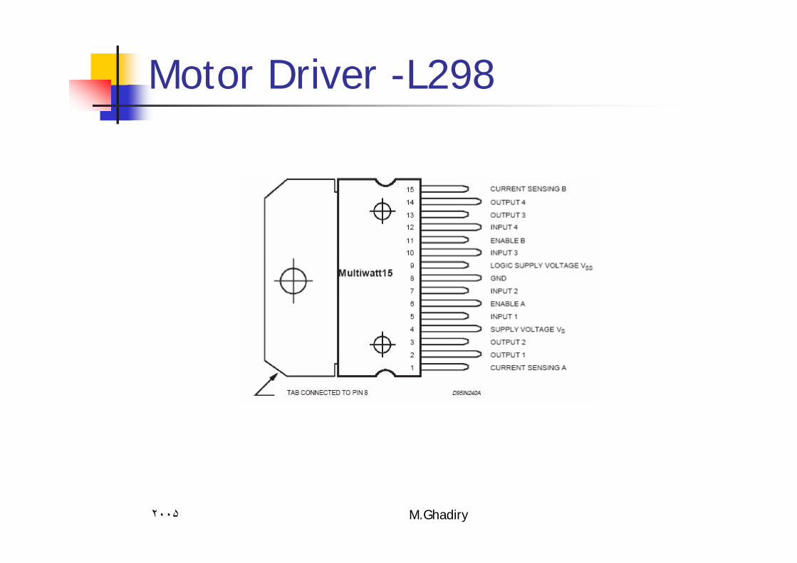
Motor Driver -L298
٢٠٠۵ M.Ghadiry
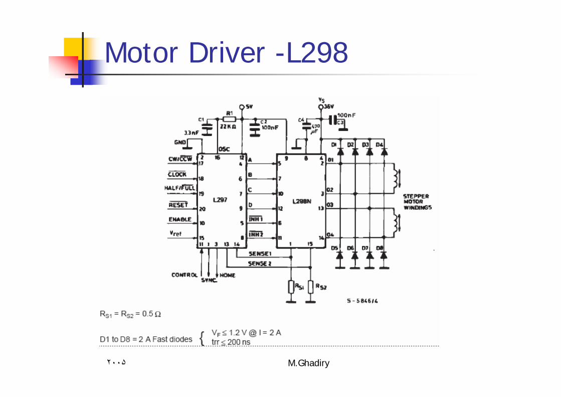
Motor Driver -L298
٢٠٠۵ M.Ghadiry
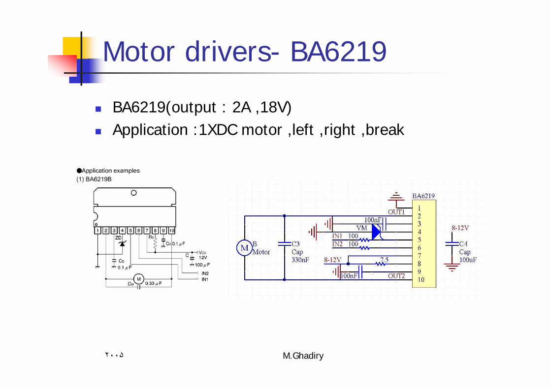
Motor drivers- BA6219
BA6219(output : 2A ,18V)Application :1XDC motor ,left ,right ,break
٢٠٠۵ M.Ghadiry
Processor & Microcontroller
Processor :Device that fetch program codes from memory and execute .A processor circuit contain ports , RAM , ROM, timer , UART,…
Microcontroller :Device contain a processor and some minimum peripherals such as few memory , timer , UART, PORT,…
٢٠٠۵ M.Ghadiry
AVR microcontrollers
AT90s2313:15 IO PINS1 UART2 TimerISP2KB flash128 B EEPROM128 KB SRAM 2 External interrupt0~12 MHZ operating frequency
٢٠٠۵ M.Ghadiry
AVR Microcontrollers
ATMEGA16:32 IO PINS (4 port)1 UART3 TimerISP16KB flash512 B EEPROM1 KB SRAM 2 External interrupt0~16 MHZ operating frequency Analog input ports
٢٠٠۵ M.Ghadiry
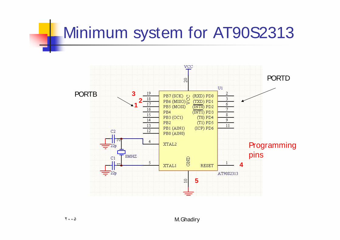
Minimum system for AT90S2313
PORTD
PORTB1
23
4
5
Programming pins
٢٠٠۵ M.Ghadiry
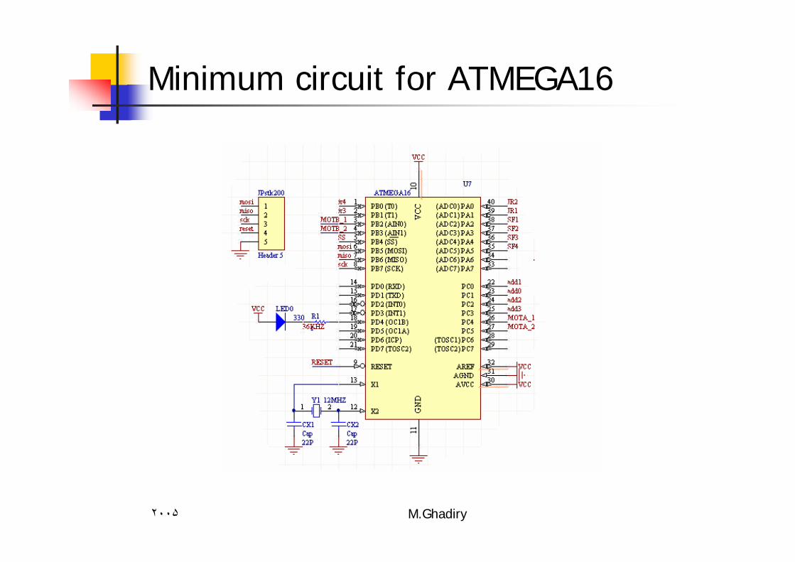
Minimum circuit for ATMEGA16

٢٠٠۵ M.Ghadiry
STK200 Programmer cable
To microcontroller
To computer
parallel
Port
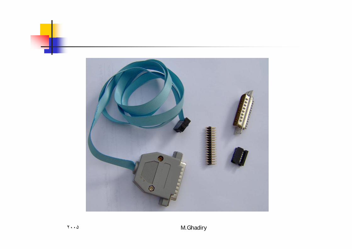
٢٠٠۵ M.Ghadiry
٢٠٠۵ M.Ghadiry
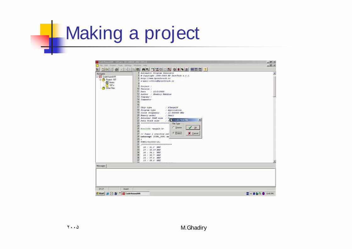
Making a project
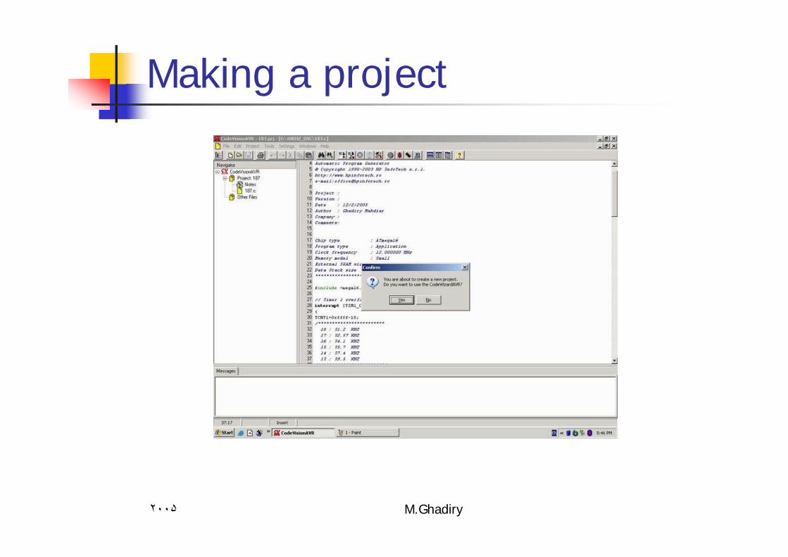
٢٠٠۵ M.Ghadiry
Making a project
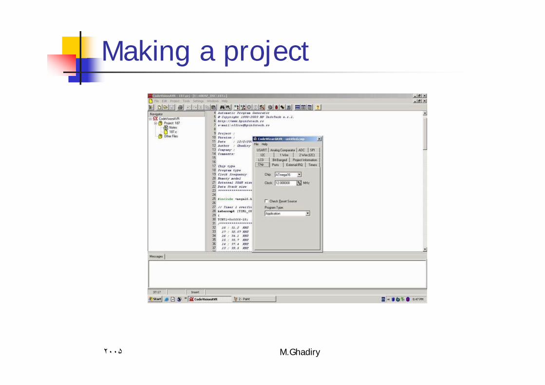
٢٠٠۵ M.Ghadiry
Making a project
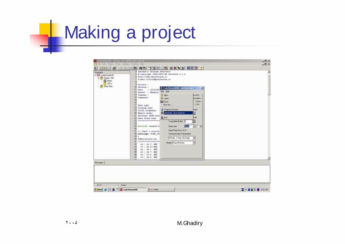
٢٠٠۵ M.Ghadiry
Making a project
٢٠٠۵ M.Ghadiry
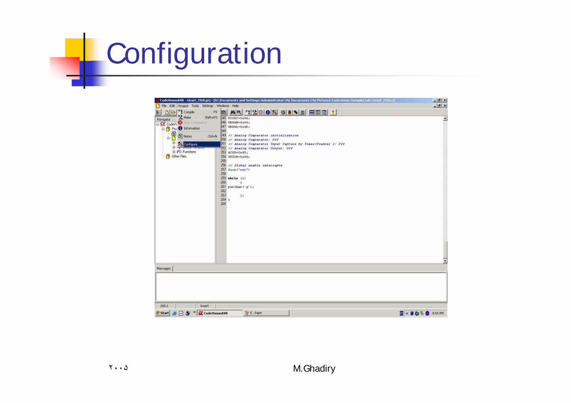
Configuration
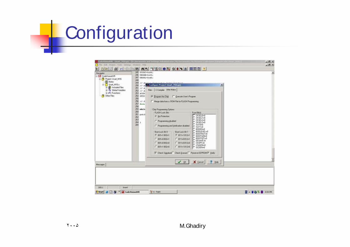
٢٠٠۵ M.Ghadiry
Configuration
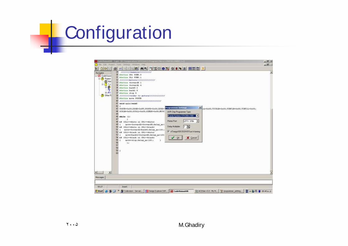
٢٠٠۵ M.Ghadiry
Configuration
٢٠٠۵ M.Ghadiry
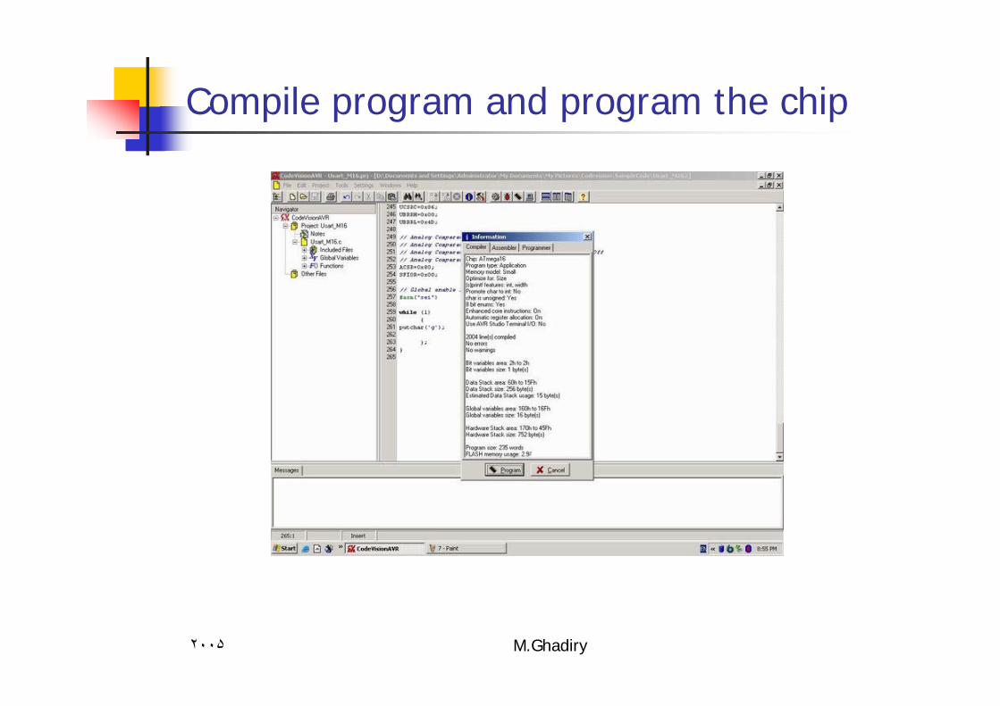
Compile program and program the chip
٢٠٠۵ M.Ghadiry
Programming with C
Each program in codevision with wizard have tree part
A : Headers :Some basic definition and function you need in your program
B: initialization part:Some basic settings for futures of device usually compiler generate them .
C: main body :Codes you generate .
٢٠٠۵ M.Ghadiry
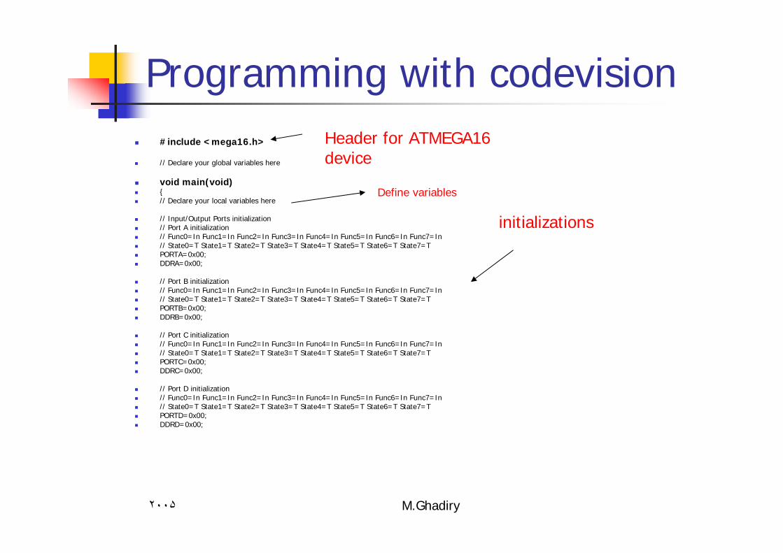
Programming with codevision#include <mega16.h>
// Declare your global variables here
void main(void){// Declare your local variables here
// Input/Output Ports initialization// Port A initialization// Func0=In Func1=In Func2=In Func3=In Func4=In Func5=In Func6=In Func7=In // State0=T State1=T State2=T State3=T State4=T State5=T State6=T State7=T PORTA=0x00;DDRA=0x00;
// Port B initialization// Func0=In Func1=In Func2=In Func3=In Func4=In Func5=In Func6=In Func7=In // State0=T State1=T State2=T State3=T State4=T State5=T State6=T State7=T PORTB=0x00;DDRB=0x00;
// Port C initialization// Func0=In Func1=In Func2=In Func3=In Func4=In Func5=In Func6=In Func7=In // State0=T State1=T State2=T State3=T State4=T State5=T State6=T State7=T PORTC=0x00;DDRC=0x00;
// Port D initialization// Func0=In Func1=In Func2=In Func3=In Func4=In Func5=In Func6=In Func7=In // State0=T State1=T State2=T State3=T State4=T State5=T State6=T State7=T PORTD=0x00;DDRD=0x00;
Header for ATMEGA16 device
initializations
Define variables

٢٠٠۵ M.Ghadiry
Programming with codevision
// Timer/Counter 0 initialization// Clock source: System Clock// Clock value: Timer 0 Stopped// Mode: Normal top=FFh// OC0 output: DisconnectedTCCR0=0x00;TCNT0=0x00;OCR0=0x00;
// Timer/Counter 1 initialization// Clock source: System Clock// Clock value: Timer 1 Stopped// Mode: Normal top=FFFFh// OC1A output: Discon.// OC1B output: Discon.// Noise Canceler: Off// Input Capture on Falling EdgeTCCR1A=0x00;TCCR1B=0x00;TCNT1H=0x00;TCNT1L=0x00;OCR1AH=0x00;OCR1AL=0x00;OCR1BH=0x00;OCR1BL=0x00;
// Timer/Counter 2 initialization// Clock source: System Clock// Clock value: Timer 2 Stopped// Mode: Normal top=FFh// OC2 output: DisconnectedASSR=0x00;TCCR2=0x00;TCNT2=0x00;OCR2=0x00;
initializations
٢٠٠۵ M.Ghadiry
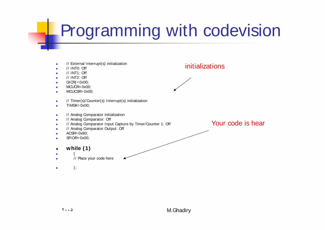
Programming with codevision
// External Interrupt(s) initialization// INT0: Off// INT1: Off// INT2: OffGICR|=0x00;MCUCR=0x00;MCUCSR=0x00;
// Timer(s)/Counter(s) Interrupt(s) initializationTIMSK=0x00;
// Analog Comparator initialization// Analog Comparator: Off// Analog Comparator Input Capture by Timer/Counter 1: Off// Analog Comparator Output: OffACSR=0x80;SFIOR=0x00;
while (1){// Place your code here
};
initializations
Your code is hear
٢٠٠۵ M.Ghadiry
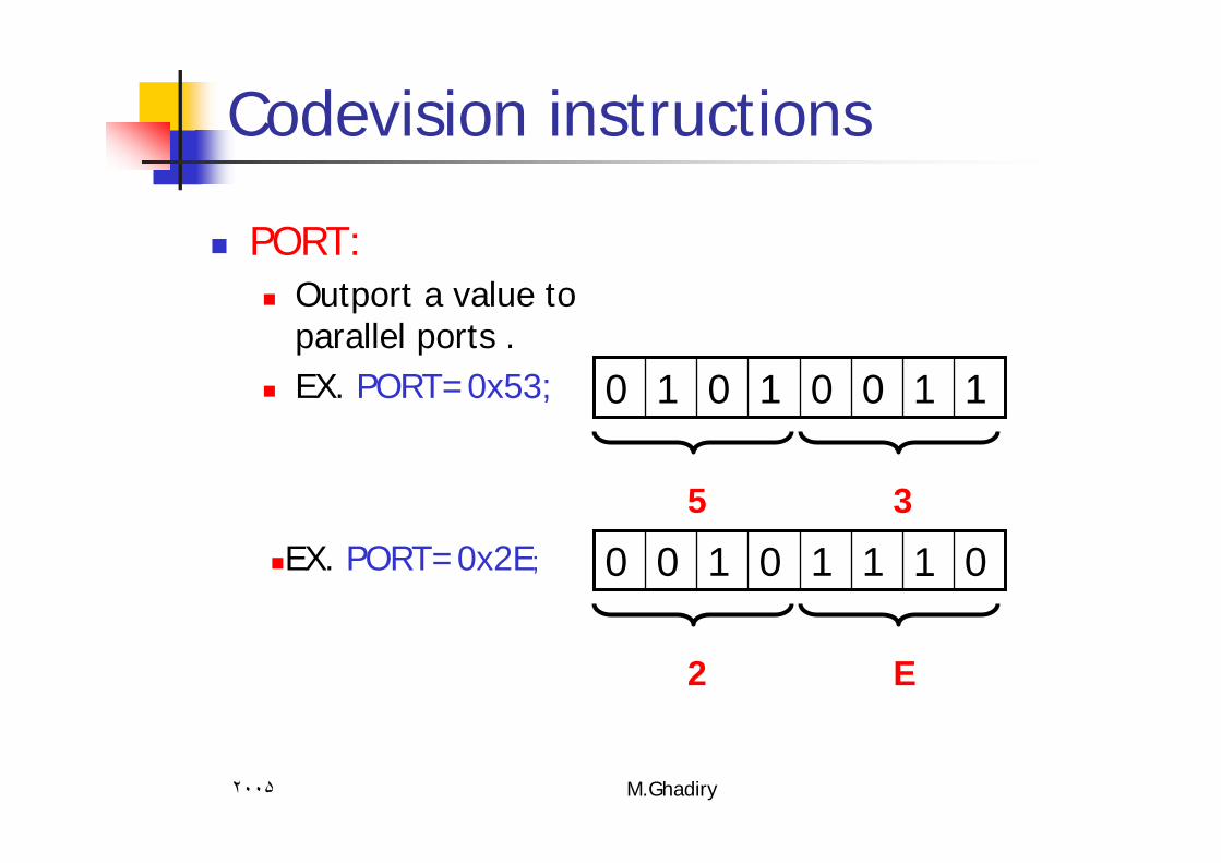
Codevision instructions
PORT:Outport a value to parallel ports .EX. PORT=0x53; 11001010
5 3
EX. PORT=0x2E; 01110100
2 E
٢٠٠۵ M.Ghadiry
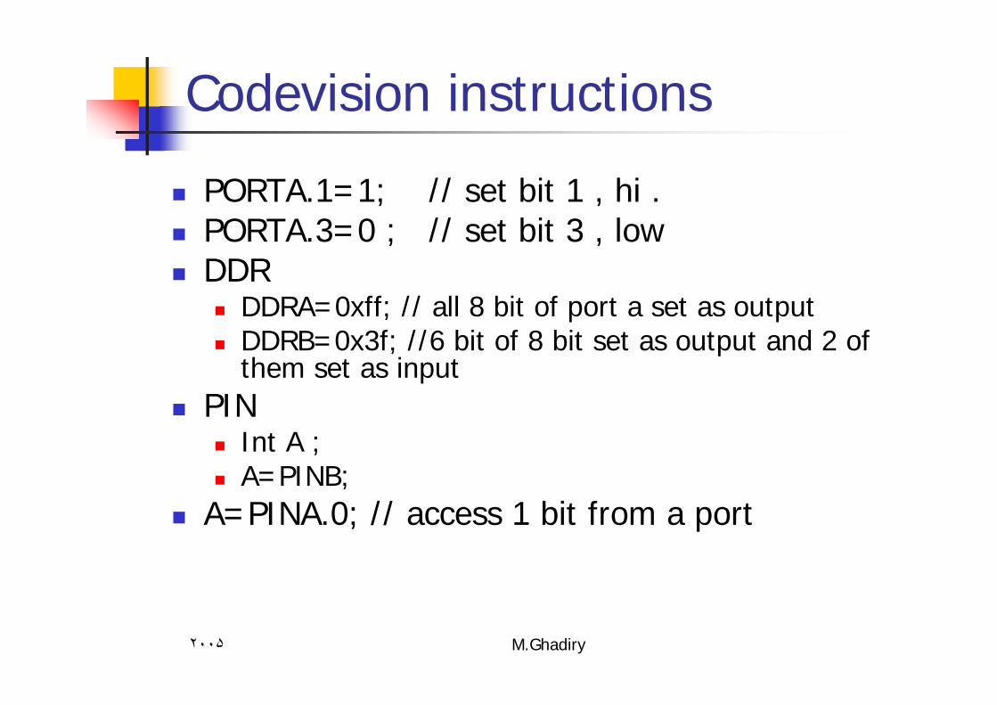
Codevision instructions
PORTA.1=1; // set bit 1 , hi .PORTA.3=0 ; // set bit 3 , low DDR
DDRA=0xff; // all 8 bit of port a set as output DDRB=0x3f; //6 bit of 8 bit set as output and 2 of them set as input
PINInt A ;A=PINB;
A=PINA.0; // access 1 bit from a port
٢٠٠۵ M.Ghadiry
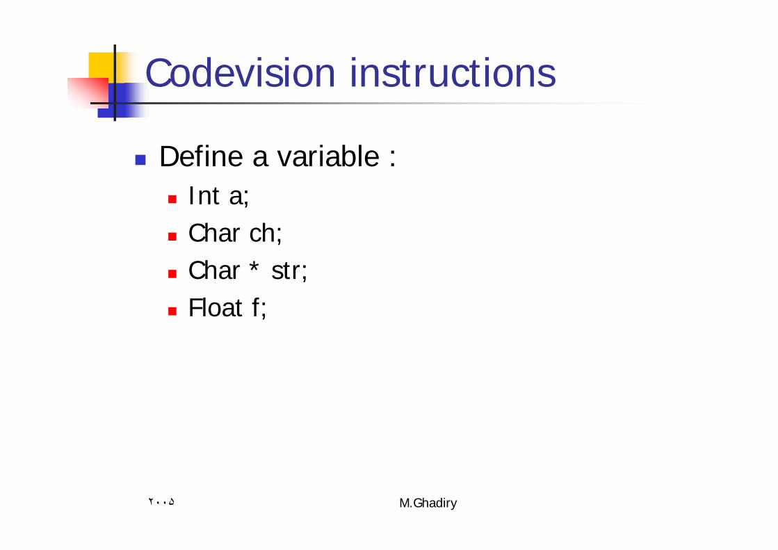
Codevision instructions
Define a variable :Int a; Char ch;Char * str;Float f;
٢٠٠۵ M.Ghadiry
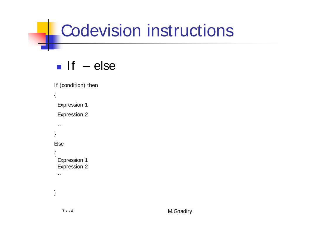
Codevision instructions
If – else If (condition) then
{
Expression 1
Expression 2
…
}
Else
{Expression 1Expression 2…
}

٢٠٠۵ M.Ghadiry
Codevision instructions
For statement
For(i=0;i<100;i++)
{
expression
}
For(i=100;i>0;i--){
expression }