beginning direct3d gameprogramming08_usingtextures_20160428_jintaeks
TRANSCRIPT
Beginning Direct3D Game Programming:
Division of Digital Contents, DongSeo University.April 2016
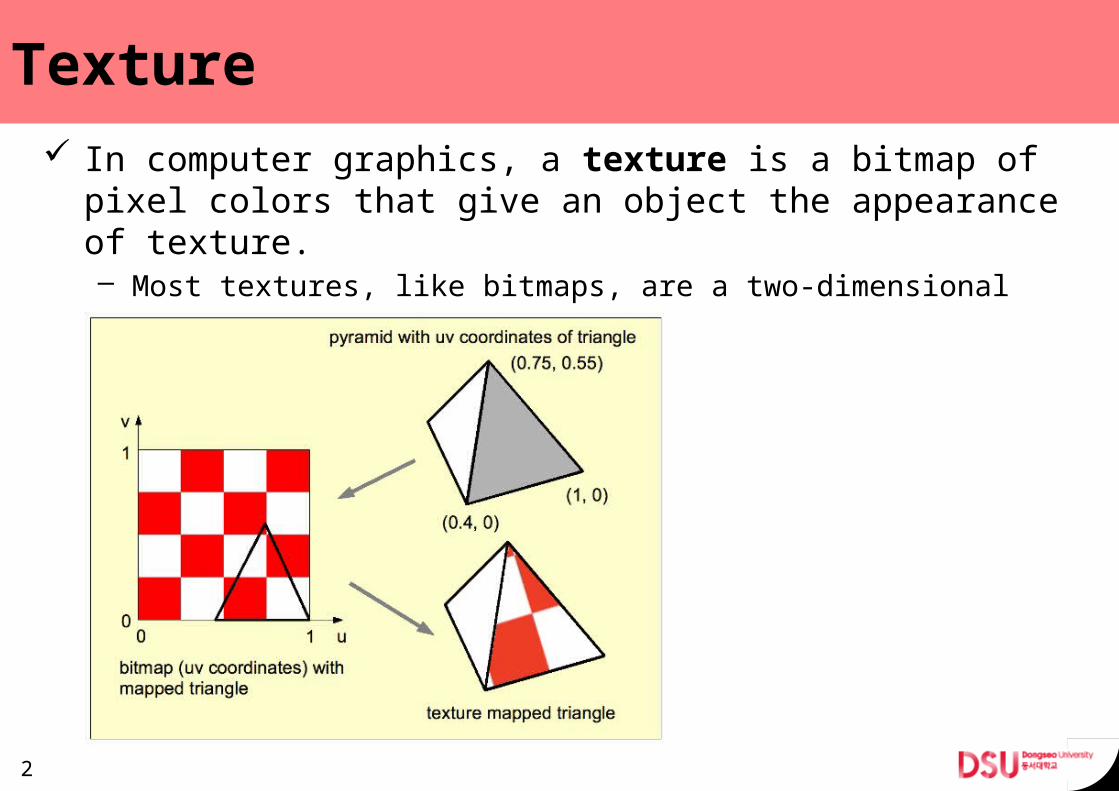
Texture In computer graphics, a texture is a bitmap of pixel col-
ors that give an object the appearance of texture.– Most textures, like bitmaps, are a two-dimensional array of color
values.
2
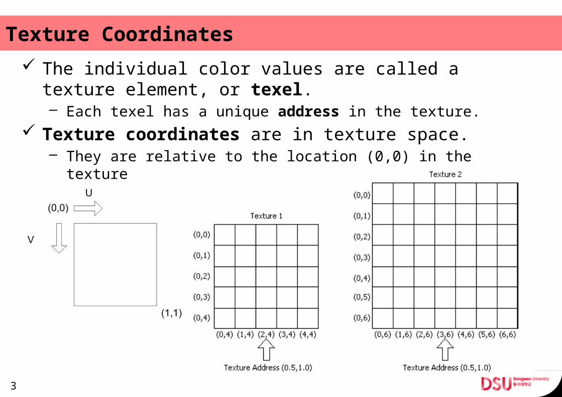
Texture Coordinates The individual color values are called a texture element,
or texel.– Each texel has a unique address in the texture.
Texture coordinates are in texture space.– They are relative to the location (0,0) in the texture
3
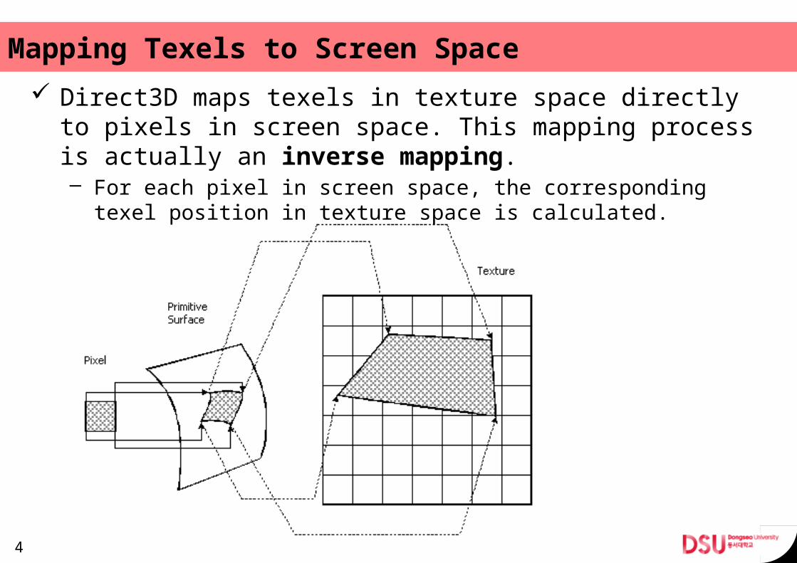
Mapping Texels to Screen Space Direct3D maps texels in texture space directly to pixels
in screen space. This mapping process is actually an in-verse mapping.– For each pixel in screen space, the corresponding texel position
in texture space is calculated.
4
Texture Coordinates and Texture Stages Texture coordinates are associated with textures by way
of texture stages. Textures get assigned to texture stages with SetTex-
ture(stageIndex, pTexture). A FVF code can define up to eight sets of texture co-
ordinates.– The data is referred to with a zero based index: 0 - 7.
5
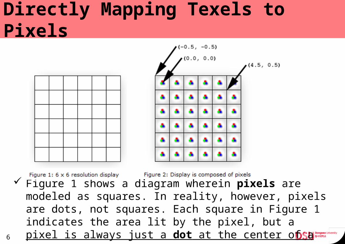
Directly Mapping Texels to Pixels
Figure 1 shows a diagram wherein pixels are modeled as squares. In reality, however, pixels are dots, not squares. Each square in Figure 1 indicates the area lit by the pixel, but a pixel is always just a dot at the center of a square.6
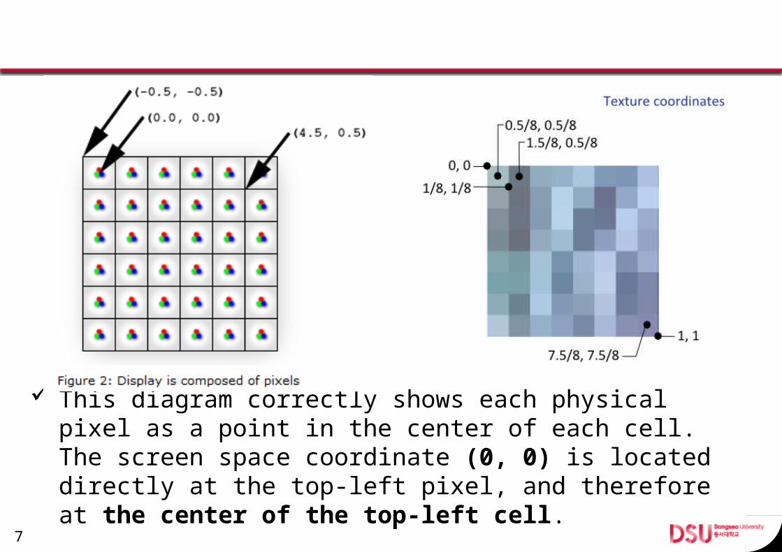
This diagram correctly shows each physical pixel as a point in the center of each cell. The screen space coor-dinate (0, 0) is located directly at the top-left pixel, and therefore at the center of the top-left cell.
7
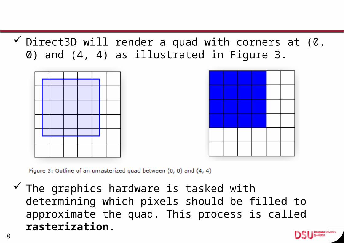
Direct3D will render a quad with corners at (0, 0) and (4, 4) as illustrated in Figure 3.
The graphics hardware is tasked with determining which pixels should be filled to approximate the quad. This process is called rasterization.
8
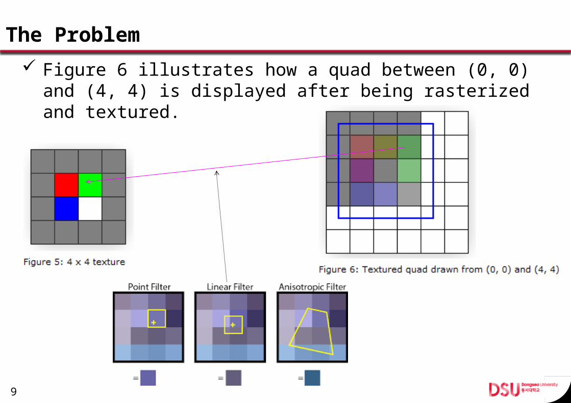
The Problem Figure 6 illustrates how a quad between (0, 0) and (4, 4)
is displayed after being rasterized and textured.
9
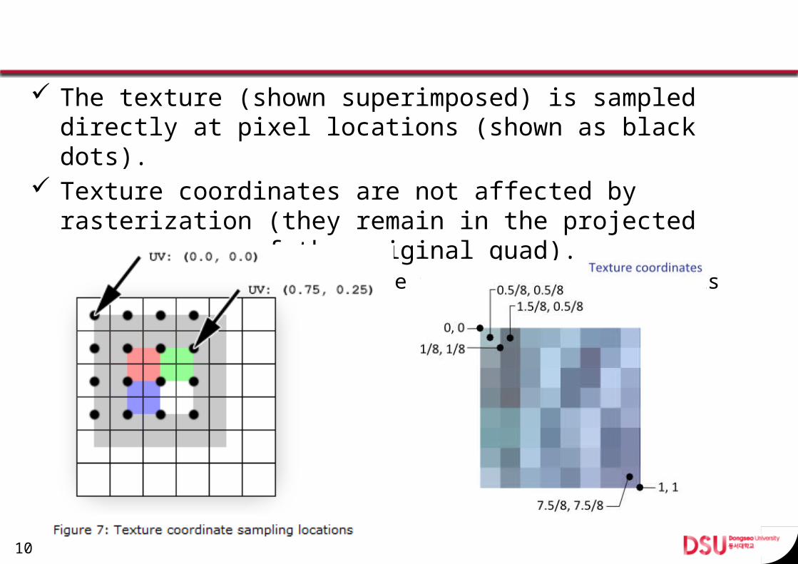
The texture (shown superimposed) is sampled directly at pixel locations (shown as black dots).
Texture coordinates are not affected by rasterization (they remain in the projected screen-space of the origi-nal quad).– The black dots show where the rasterization pixels are.
10
Solution
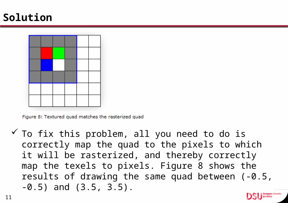
To fix this problem, all you need to do is correctly map the quad to the pixels to which it will be rasterized, and thereby correctly map the texels to pixels. Figure 8 shows the results of drawing the same quad between (-0.5, -0.5) and (3.5, 3.5).
11
Texturing Addressing Modes Typically, the u- and v-texture coordinates that you as-
sign to a vertex are in the range of 0.0 to 1.0 inclusive. By assigning texture coordinates outside that range, you
can create certain special texturing effects. You control what Direct3D does with texture coordinates
that are outside the [0.0, 1.0] range by setting the tex-ture addressing mode.– Wrap Texture Address Mode– Mirror Texture Address Mode– Clamp Texture Address Mode– Border Color Texture Address Mode
12

Setting the Addressing Mode You can set texture addressing modes for individual tex-
ture stages by calling the IDirect3DDevice9::SetSamplerState method.typedef enum D3DSAMPLERSTATETYPE{ D3DSAMP_ADDRESSU = 1, D3DSAMP_ADDRESSV = 2, D3DSAMP_ADDRESSW = 3, D3DSAMP_BORDERCOLOR = 4, D3DSAMP_MAGFILTER = 5, D3DSAMP_MINFILTER = 6, D3DSAMP_MIPFILTER = 7, D3DSAMP_MIPMAPLODBIAS = 8, D3DSAMP_MAXMIPLEVEL = 9, D3DSAMP_FORCE_DWORD = 0x7fffffff,} D3DSAMPLERSTATETYPE, *LPD3DSAMPLERSTATETYPE;
13
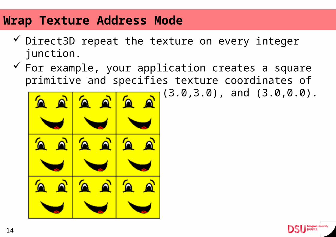
Wrap Texture Address Mode Direct3D repeat the texture on every integer junction. For example, your application creates a square primitive
and specifies texture coordinates of (0.0,0.0), (0.0,3.0), (3.0,3.0), and (3.0,0.0).
14
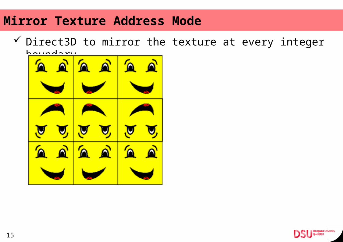
Mirror Texture Address Mode Direct3D to mirror the texture at every integer boundary.
15
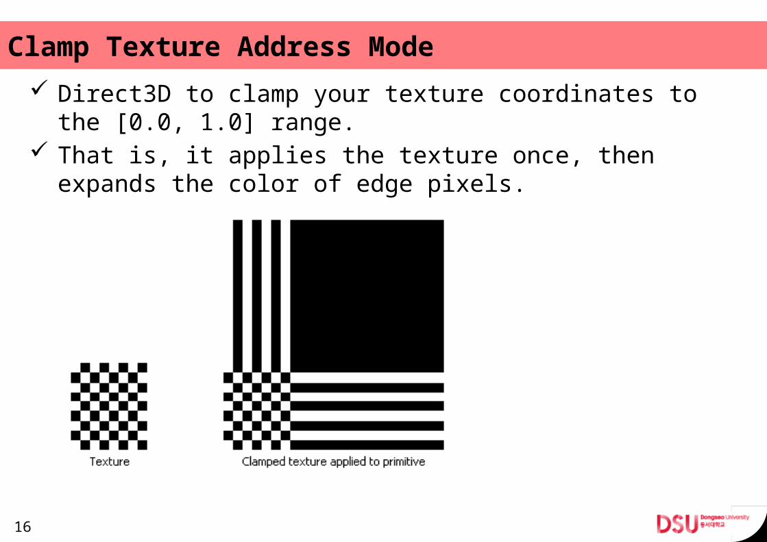
Clamp Texture Address Mode Direct3D to clamp your texture coordinates to the [0.0,
1.0] range. That is, it applies the texture once, then expands the
color of edge pixels.
16
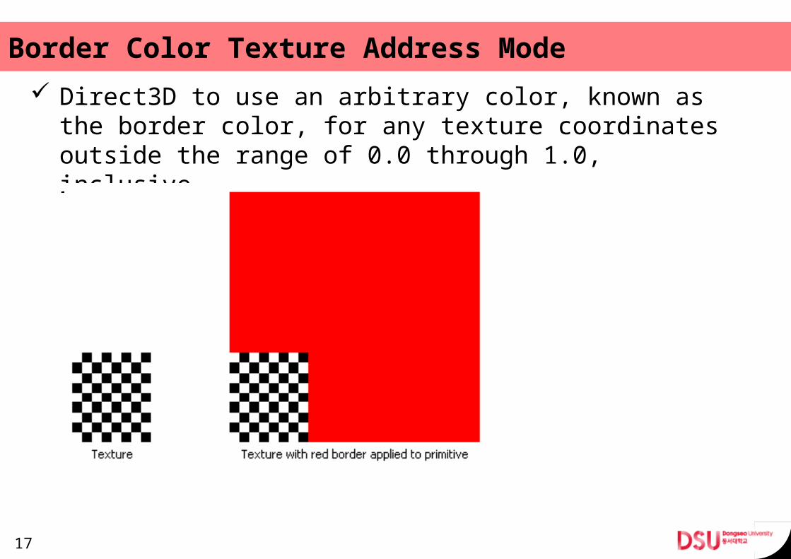
Border Color Texture Address Mode Direct3D to use an arbitrary color, known as the border
color, for any texture coordinates outside the range of 0.0 through 1.0, inclusive.
17

Texture Filtering When Direct3D renders a primitive, it maps the 3D prim-
itive onto a 2D screen. If the primitive has a texture, Di-rect3D must use that texture to produce a color for each pixel in the primitive's 2D rendered image.
For every pixel in the primitive's on-screen image, it must obtain a color value from the texture.– Nearest-Point Sampling– Bilinear Texture Filtering– Anisotropic Texture Filtering– Texture Filtering with Mipmaps
18
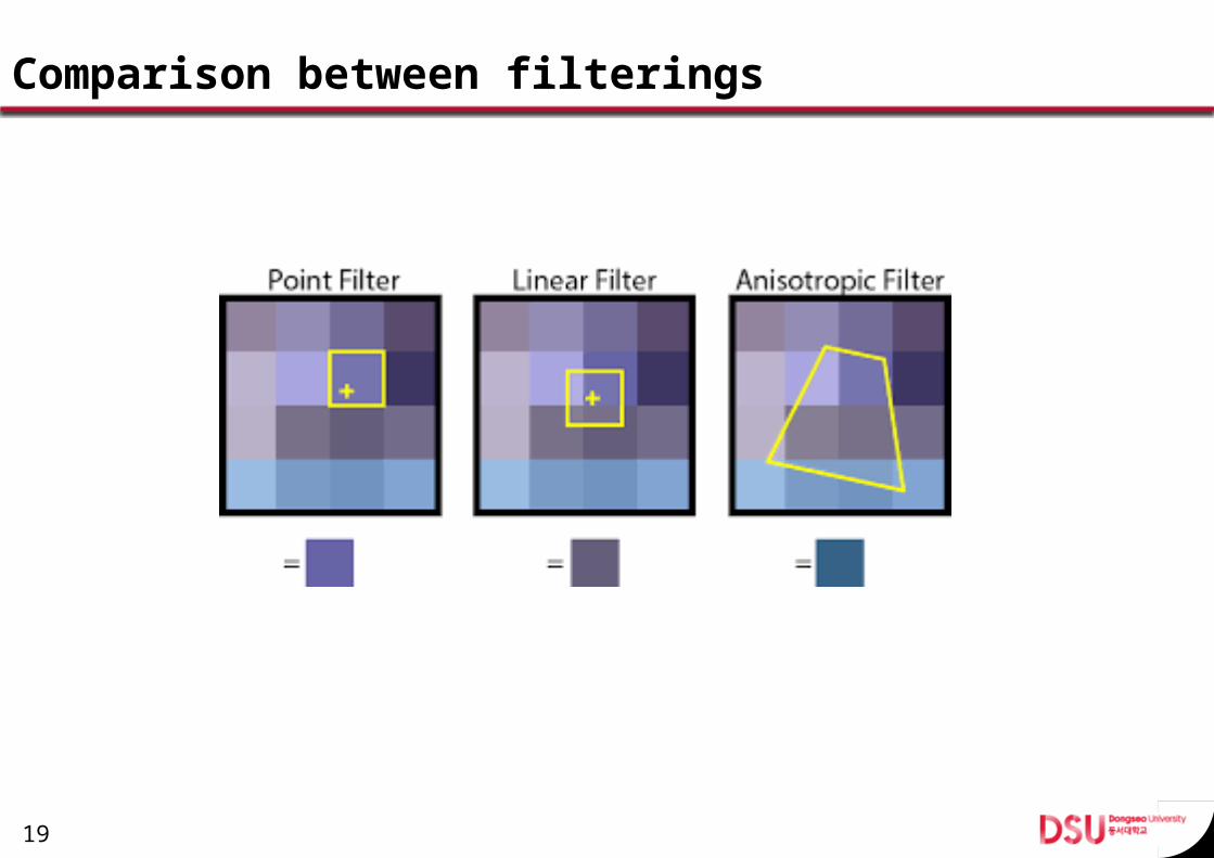
Comparison between filterings
19
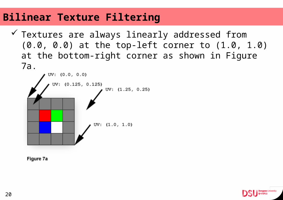
Bilinear Texture Filtering Textures are always linearly addressed from (0.0, 0.0) at
the top-left corner to (1.0, 1.0) at the bottom-right cor-ner as shown in Figure 7a.
20
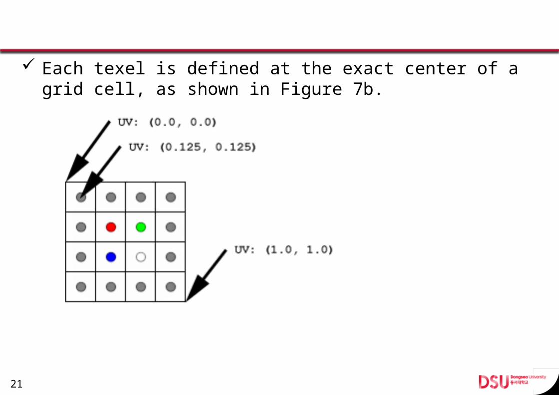
Each texel is defined at the exact center of a grid cell, as shown in Figure 7b.
21
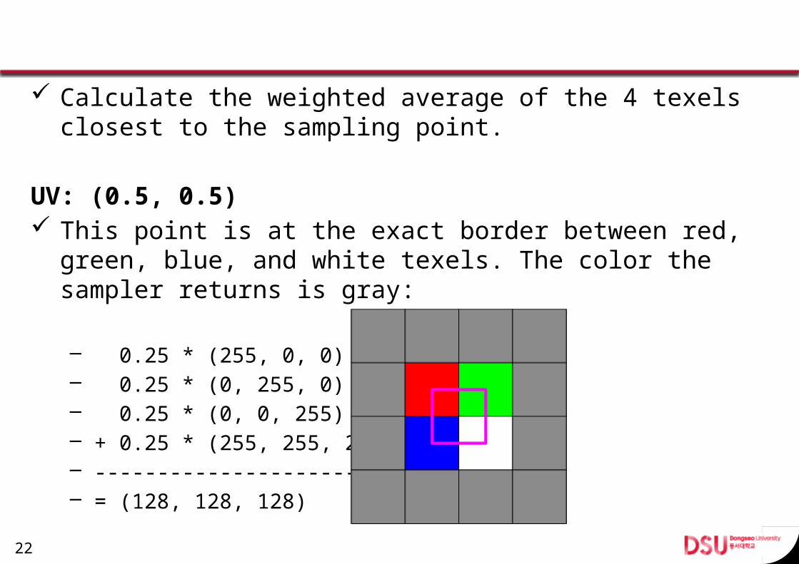
Calculate the weighted average of the 4 texels closest to the sampling point.
UV: (0.5, 0.5) This point is at the exact border between red, green,
blue, and white texels. The color the sampler returns is gray:
– 0.25 * (255, 0, 0)– 0.25 * (0, 255, 0) – 0.25 * (0, 0, 255) – + 0.25 * (255, 255, 255) – ------------------------– = (128, 128, 128)
22
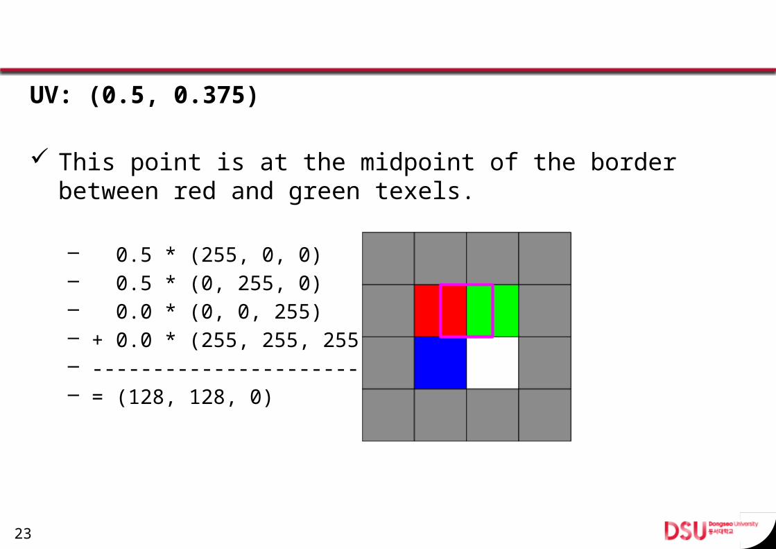
UV: (0.5, 0.375)
This point is at the midpoint of the border between red and green texels.
– 0.5 * (255, 0, 0)– 0.5 * (0, 255, 0) – 0.0 * (0, 0, 255) – + 0.0 * (255, 255, 255) – ------------------------– = (128, 128, 0)
23
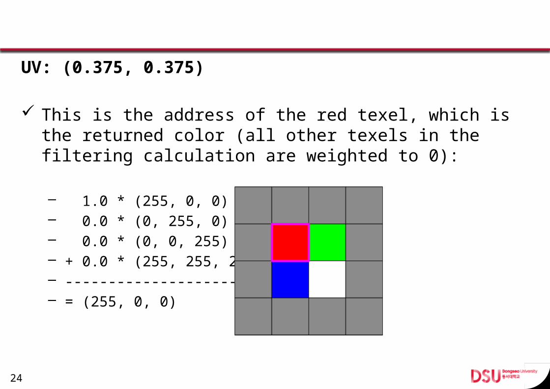
UV: (0.375, 0.375)
This is the address of the red texel, which is the returned color (all other texels in the filtering calculation are weighted to 0):
– 1.0 * (255, 0, 0)– 0.0 * (0, 255, 0) – 0.0 * (0, 0, 255) – + 0.0 * (255, 255, 255) – ------------------------– = (255, 0, 0)
24
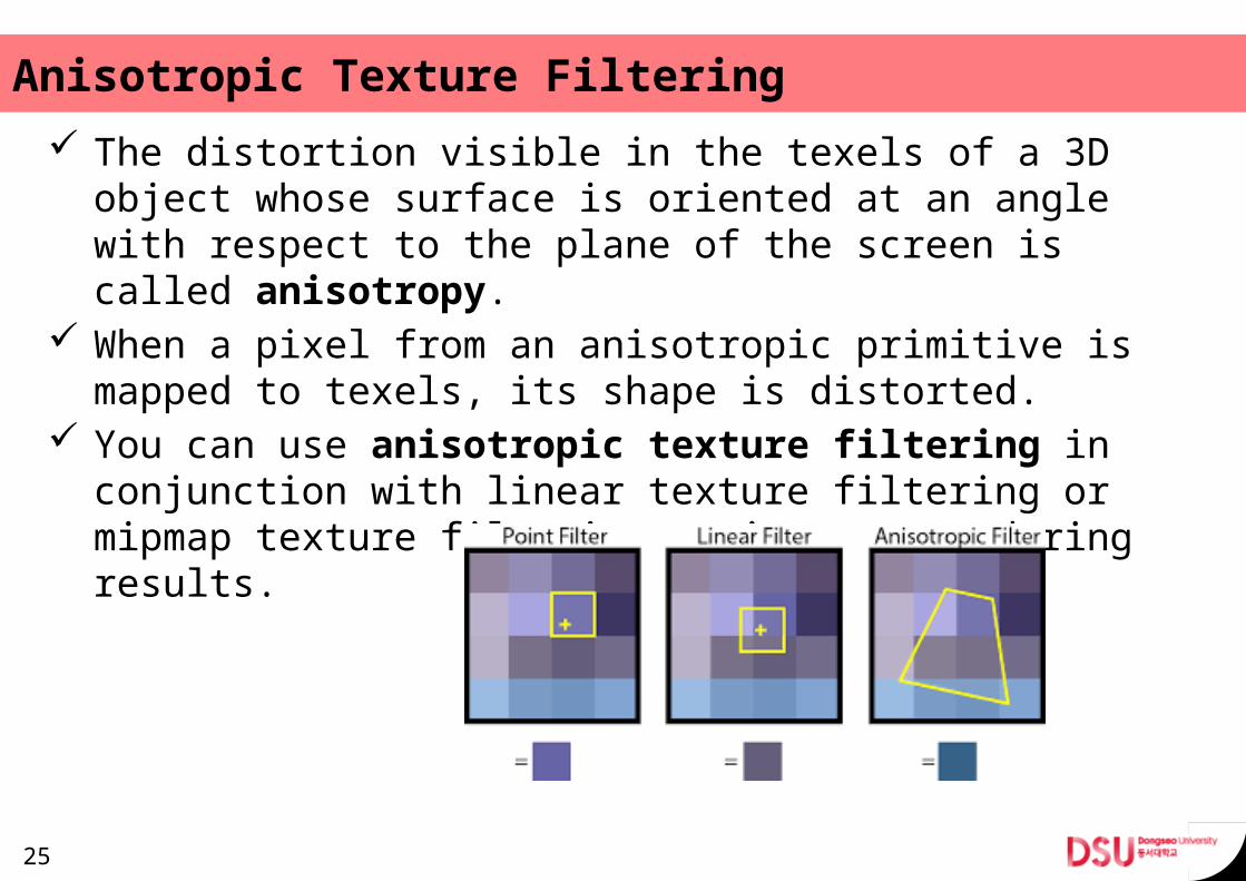
Anisotropic Texture Filtering The distortion visible in the texels of a 3D object whose
surface is oriented at an angle with respect to the plane of the screen is called anisotropy.
When a pixel from an anisotropic primitive is mapped to texels, its shape is distorted.
You can use anisotropic texture filtering in conjunc-tion with linear texture filtering or mipmap texture filter-ing to improve rendering results.
25
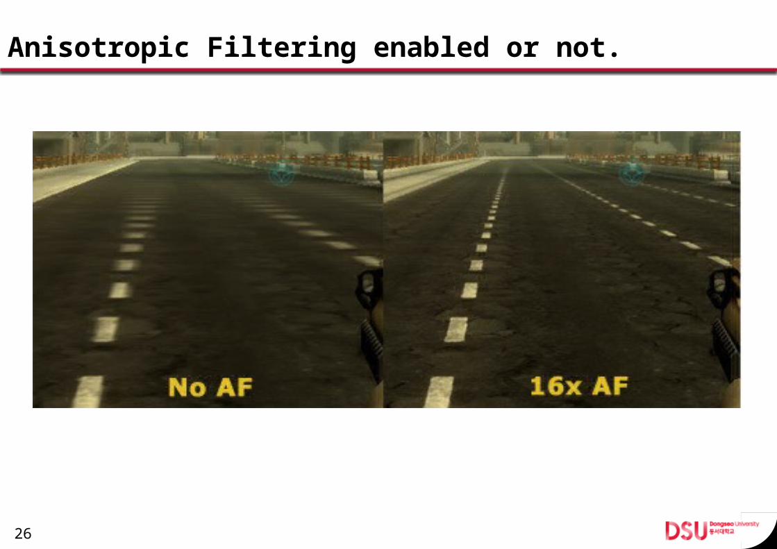
Anisotropic Filtering enabled or not.
26
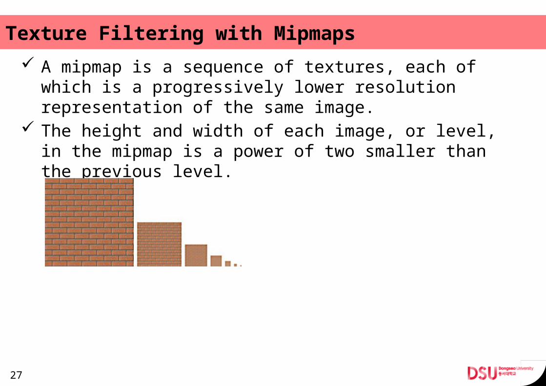
Texture Filtering with Mipmaps A mipmap is a sequence of textures, each of which is a
progressively lower resolution representation of the same image.
The height and width of each image, or level, in the mipmap is a power of two smaller than the previous level.
27
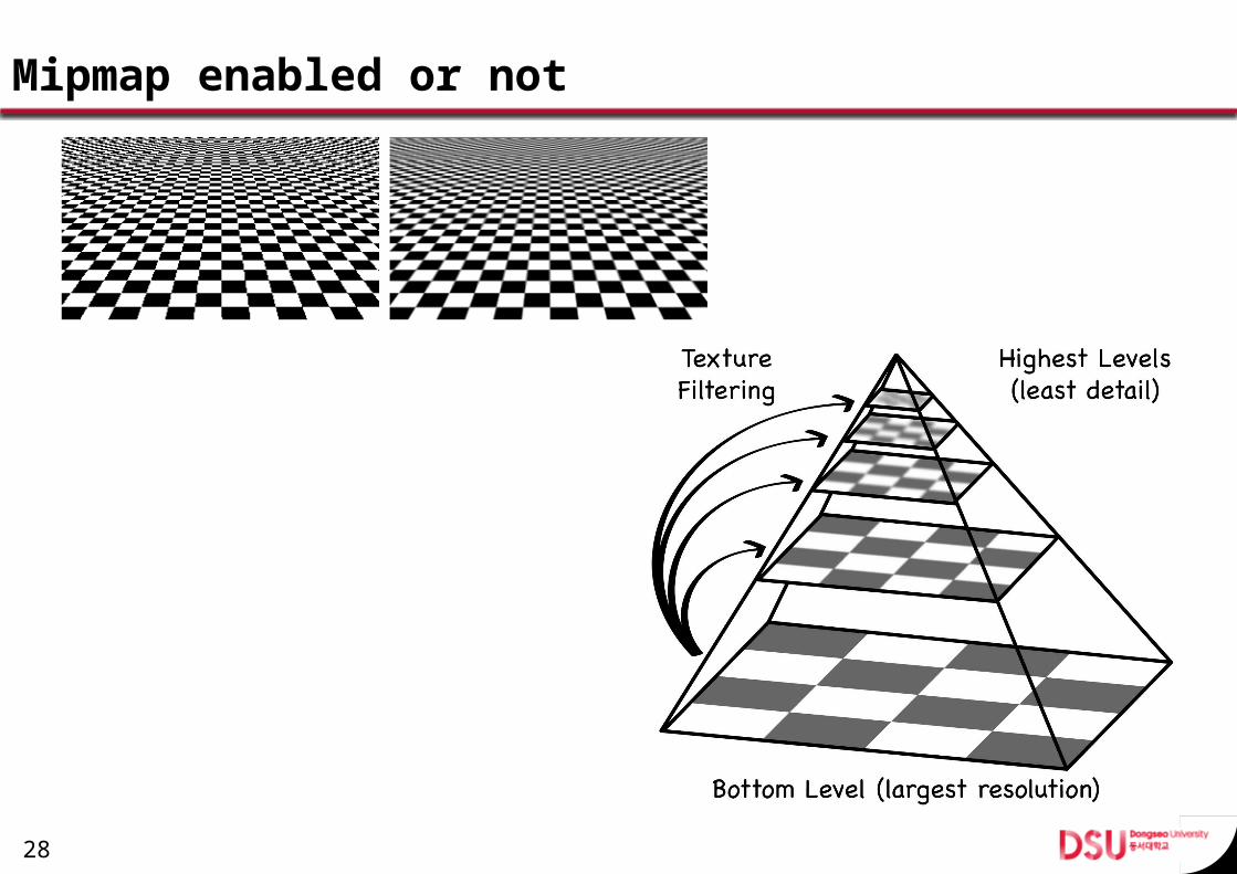
Mipmap enabled or not
28
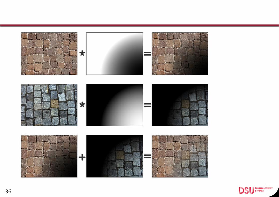
Texture Blending Direct3D can blend as many as eight textures onto prim-
itives in a single pass. An application employs multiple texture blending to ap-
ply textures, shadows, specular lighting, diffuse lighting, and other special effects in a single pass.
29
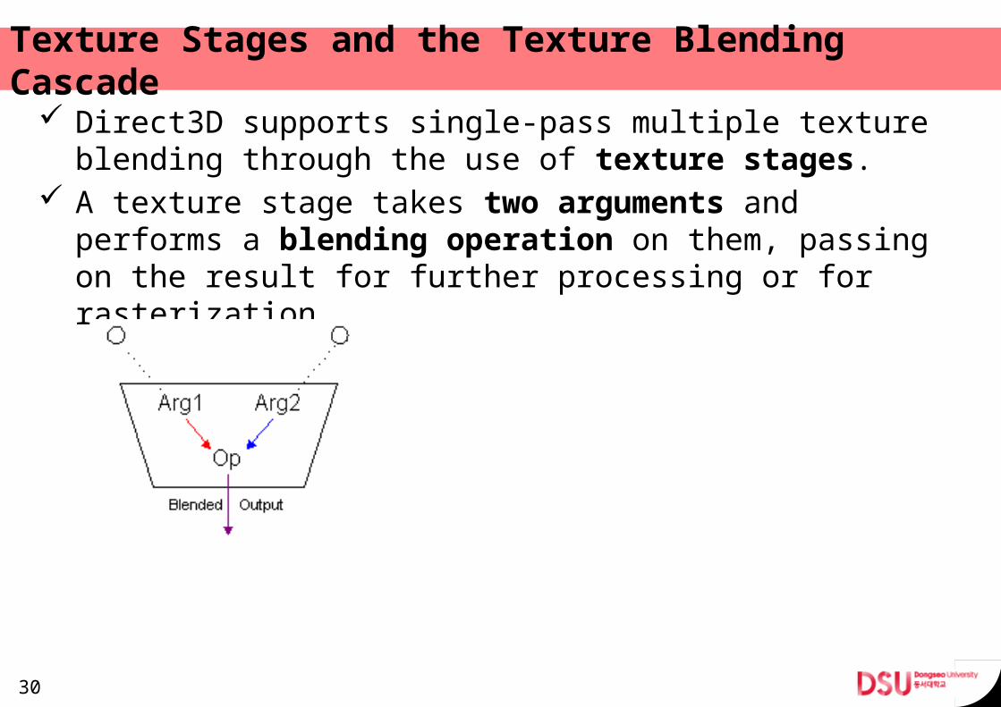
Texture Stages and the Texture Blending Cas-cade
Direct3D supports single-pass multiple texture blending through the use of texture stages.
A texture stage takes two arguments and performs a blending operation on them, passing on the result for further processing or for rasterization.
30
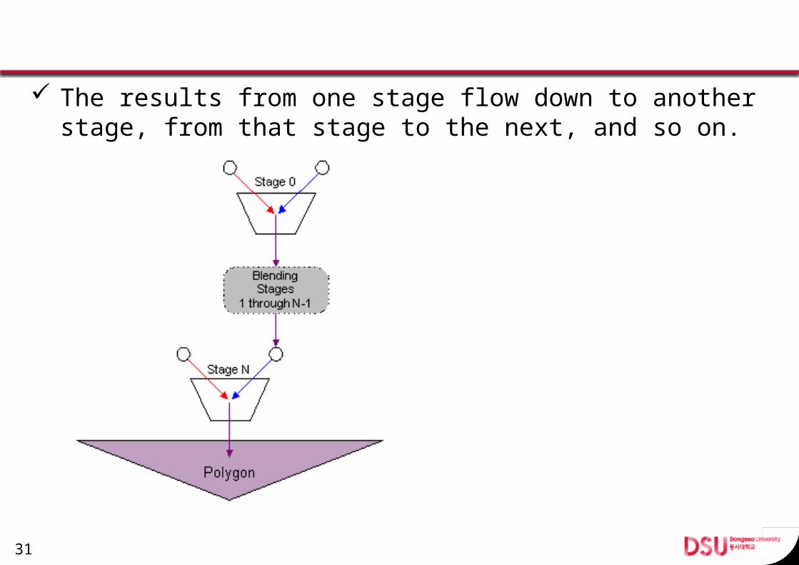
The results from one stage flow down to another stage, from that stage to the next, and so on.
31
Texture Blending Operations and Arguments Applications control what information from a texture
stage is used by calling IDirect3DDevice9::SetTextureStageState.
You can set separate operations for the color and alpha channels, and each operation uses two arguments
Texture blending arguments use the D3DTSS_COLORARG1, D3DTSS_COLORARG2, D3DTSS_ALPHARG1, and D3DTSS_ALPHARG2 members of the D3DTEXTURESTAGESTATETYPE enumerated type.
32
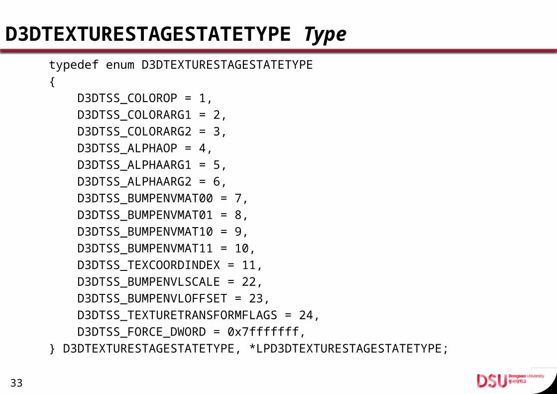
D3DTEXTURESTAGESTATETYPE Typetypedef enum D3DTEXTURESTAGESTATETYPE{ D3DTSS_COLOROP = 1, D3DTSS_COLORARG1 = 2, D3DTSS_COLORARG2 = 3, D3DTSS_ALPHAOP = 4, D3DTSS_ALPHAARG1 = 5, D3DTSS_ALPHAARG2 = 6, D3DTSS_BUMPENVMAT00 = 7, D3DTSS_BUMPENVMAT01 = 8, D3DTSS_BUMPENVMAT10 = 9, D3DTSS_BUMPENVMAT11 = 10, D3DTSS_TEXCOORDINDEX = 11, D3DTSS_BUMPENVLSCALE = 22, D3DTSS_BUMPENVLOFFSET = 23, D3DTSS_TEXTURETRANSFORMFLAGS = 24, D3DTSS_FORCE_DWORD = 0x7fffffff,} D3DTEXTURESTAGESTATETYPE, *LPD3DTEXTURESTAGESTATETYPE;
33
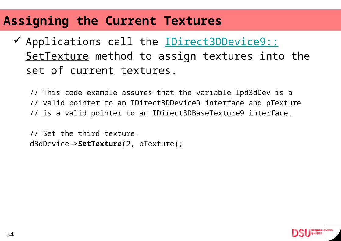
Assigning the Current Textures Applications call the IDirect3DDevice9::SetTexture
method to assign textures into the set of current tex-tures.// This code example assumes that the variable lpd3dDev is a// valid pointer to an IDirect3DDevice9 interface and pTexture// is a valid pointer to an IDirect3DBaseTexture9 interface.
// Set the third texture.d3dDevice->SetTexture(2, pTexture);
34
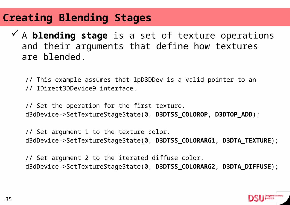
Creating Blending Stages A blending stage is a set of texture operations and
their arguments that define how textures are blended.
// This example assumes that lpD3DDev is a valid pointer to an// IDirect3DDevice9 interface.
// Set the operation for the first texture.d3dDevice->SetTextureStageState(0, D3DTSS_COLOROP, D3DTOP_ADD);
// Set argument 1 to the texture color.d3dDevice->SetTextureStageState(0, D3DTSS_COLORARG1, D3DTA_TEXTURE);
// Set argument 2 to the iterated diffuse color.d3dDevice->SetTextureStageState(0, D3DTSS_COLORARG2, D3DTA_DIFFUSE);
35
36
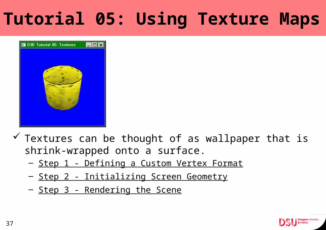
Tutorial 05: Using Texture Maps
Textures can be thought of as wallpaper that is shrink-wrapped onto a surface.– Step 1 - Defining a Custom Vertex Format – Step 2 - Initializing Screen Geometry – Step 3 - Rendering the Scene
37
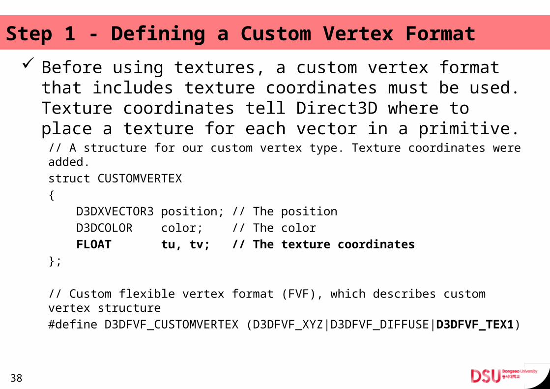
Step 1 - Defining a Custom Vertex Format Before using textures, a custom vertex format that in-
cludes texture coordinates must be used. Texture coor-dinates tell Direct3D where to place a texture for each vector in a primitive.// A structure for our custom vertex type. Texture coordinates were added.struct CUSTOMVERTEX{ D3DXVECTOR3 position; // The position D3DCOLOR color; // The color FLOAT tu, tv; // The texture coordinates};
// Custom flexible vertex format (FVF), which describes custom vertex structure#define D3DFVF_CUSTOMVERTEX (D3DFVF_XYZ|D3DFVF_DIFFUSE|D3DFVF_TEX1)
38
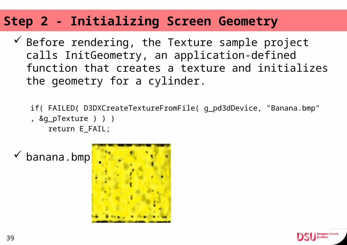
Step 2 - Initializing Screen Geometry Before rendering, the Texture sample project calls Init-
Geometry, an application-defined function that creates a texture and initializes the geometry for a cylinder.
if( FAILED( D3DXCreateTextureFromFile( g_pd3dDevice, "Banana.bmp", &g_pTexture ) ) ) return E_FAIL;
banana.bmp
39
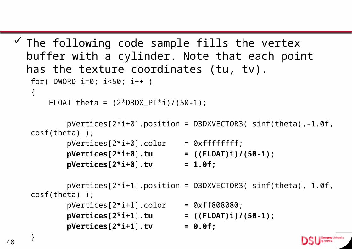
The following code sample fills the vertex buffer with a cylinder. Note that each point has the texture coordi-nates (tu, tv).for( DWORD i=0; i<50; i++ ){ FLOAT theta = (2*D3DX_PI*i)/(50-1);
pVertices[2*i+0].position = D3DXVECTOR3( sinf(theta),-1.0f, cosf(theta) ); pVertices[2*i+0].color = 0xffffffff; pVertices[2*i+0].tu = ((FLOAT)i)/(50-1); pVertices[2*i+0].tv = 1.0f;
pVertices[2*i+1].position = D3DXVECTOR3( sinf(theta), 1.0f, cosf(theta) ); pVertices[2*i+1].color = 0xff808080; pVertices[2*i+1].tu = ((FLOAT)i)/(50-1); pVertices[2*i+1].tv = 0.0f;}
40
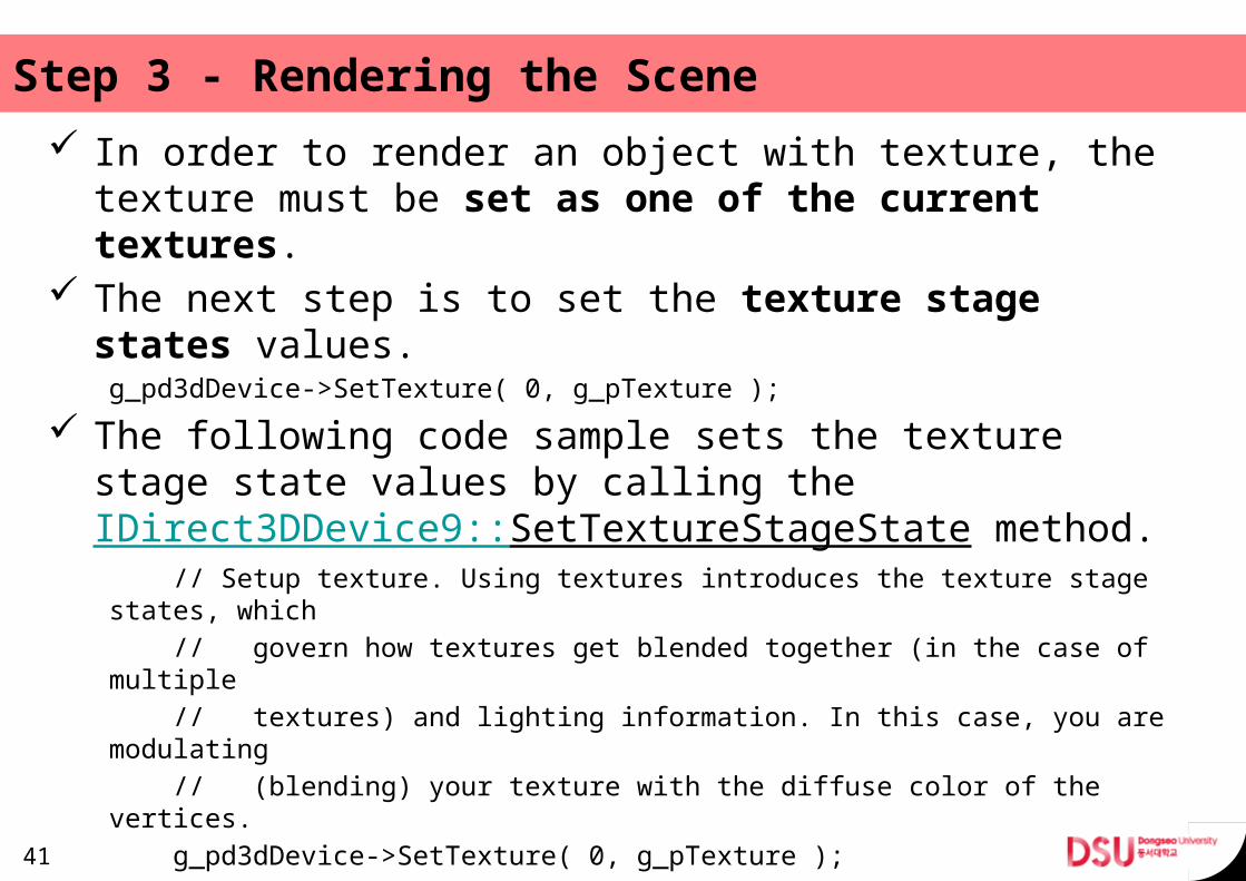
Step 3 - Rendering the Scene In order to render an object with texture, the texture
must be set as one of the current textures. The next step is to set the texture stage states val-
ues.g_pd3dDevice->SetTexture( 0, g_pTexture );
The following code sample sets the texture stage state values by calling the IDirect3DDevice9::SetTextureStageState method. // Setup texture. Using textures introduces the texture stage states, which // govern how textures get blended together (in the case of multiple // textures) and lighting information. In this case, you are modulating // (blending) your texture with the diffuse color of the vertices. g_pd3dDevice->SetTexture( 0, g_pTexture ); g_pd3dDevice->SetTextureStageState( 0, D3DTSS_COLOROP, D3DTOP_MODULATE ); g_pd3dDevice->SetTextureStageState( 0, D3DTSS_COLORARG1, D3DTA_TEXTURE ); g_pd3dDevice->SetTextureStageState( 0, D3DTSS_COLORARG2, D3DTA_DIFFUSE ); g_pd3dDevice->SetTextureStageState( 0, D3DTSS_ALPHAOP, D3DTOP_DISABLE );
41
References
42