chap3 sts till 29-nov12
TRANSCRIPT

7/29/2019 Chap3 STS Till 29-Nov12
http://slidepdf.com/reader/full/chap3-sts-till-29-nov12 1/52
Department of Mechanical EngineeringHITEC University Taxila
1
Components of Solar Thermal Systems
Components and Subsystems of Solar Thermal Installation
Collectors
Storage Plan
Heat Exchangers
Pumps and Expansion
Chambers
Controller
Other Components

7/29/2019 Chap3 STS Till 29-Nov12
http://slidepdf.com/reader/full/chap3-sts-till-29-nov12 2/52
Department of Mechanical EngineeringHITEC University Taxila
2
Typical Solar Installations With Main Components
Components of Solar Thermal Systems
Solar Collector mounted on the roofconverts the light that penetrates its glasspanes (short-wave radiation) into heat. Thecollector is therefore the link between thesun and the hot water user
Forced Circulation
Fig. 3.1
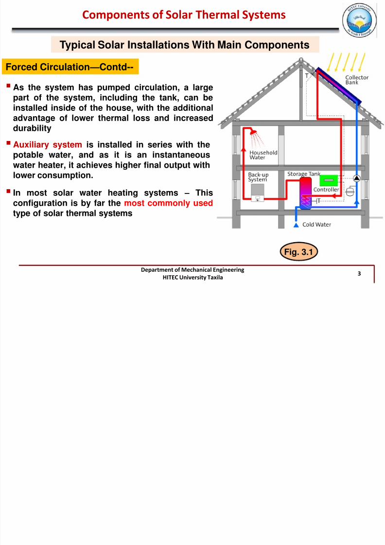
image shows a solar heating installationproviding hot water in a house
It is an indirect, closed loop, pumped system
fluid that flows through the collectors is isolatedfrom the potable water, which permits use ofantifreeze and anti-corrosive agents; thesereduce freezing and corrosion problems andtherefore increase the durability and reliability ofthe system.
7/29/2019 Chap3 STS Till 29-Nov12
http://slidepdf.com/reader/full/chap3-sts-till-29-nov12 3/52
Department of Mechanical EngineeringHITEC University Taxila
3
Typical Solar Installations With Main Components
Components of Solar Thermal Systems
Forced Circulation—Contd--
Fig. 3.1
As the system has pumped circulation, a largepart of the system, including the tank, can beinstalled inside of the house, with the additionaladvantage of lower thermal loss and increaseddurability
Auxiliary system is installed in series with thepotable water, and as it is an instantaneouswater heater, it achieves higher final output withlower consumption.
In most solar water heating systems – This
configuration is by far the most commonly usedtype of solar thermal systems

7/29/2019 Chap3 STS Till 29-Nov12
http://slidepdf.com/reader/full/chap3-sts-till-29-nov12 4/52
Department of Mechanical EngineeringHITEC University Taxila
4
Typical Solar Installations With Main Components
Components of Solar Thermal Systems
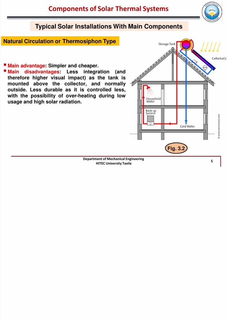
Natural Circulation or Thermosiphon Type
This solar heating installation has advantagesand disadvantages over the previous system
Fig. 3.2
It has Natural or Thermosyphon circulation. It
can be an indirect system or a direct system,which is only feasible for certain water qualities,and when no risk of freezing exists
Systems are designed based on the principlethat hot water rises. These are calledthermosyphon systems , and the storage tank isalmost always located outdoors, directly on top
of the solar collector
7/29/2019 Chap3 STS Till 29-Nov12
http://slidepdf.com/reader/full/chap3-sts-till-29-nov12 5/52
Department of Mechanical EngineeringHITEC University Taxila
5
Typical Solar Installations With Main Components
Components of Solar Thermal Systems
Natural Circulation or Thermosiphon Type
Main advantage: Simpler and cheaper.Main disadvantages: Less integration (and
therefore higher visual impact) as the tank ismounted above the collector, and normallyoutside. Less durable as it is controlled less,with the possibility of over-heating during lowusage and high solar radiation.
Fig. 3.2

7/29/2019 Chap3 STS Till 29-Nov12
http://slidepdf.com/reader/full/chap3-sts-till-29-nov12 6/52
Department of Mechanical EngineeringHITEC University Taxila
6
Components of a Solar Thermal Installation – Forced Circulation
Components of Solar Thermal Systems
components in a typical solarinstallation:
Collector area
Tank
Pump
Piping
Expansion vessel
Purge unit (air vent)
Various types of valves
Temperature and pressure
sensors
Fig. 3.3

7/29/2019 Chap3 STS Till 29-Nov12
http://slidepdf.com/reader/full/chap3-sts-till-29-nov12 7/52
Department of Mechanical EngineeringHITEC University Taxila
7
Components of a Solar Thermal Installation – Natural Circulation
Components of Solar Thermal Systems
Components in a typicalthermosiphon solar installation:
Collector area
Tank
Piping
Expansion vessel
Purge unit
Various types of valves
Temperature and pressure
sensors.
Fig. 3.4

7/29/2019 Chap3 STS Till 29-Nov12
http://slidepdf.com/reader/full/chap3-sts-till-29-nov12 8/52
Department of Mechanical EngineeringHITEC University Taxila
8
Solar Energy Collectors
Components of Solar Thermal Systems
Solar energy collectors are special kinds of heat exchangers that transform solarradiation energy to internal energy of the transport medium
There are basically two types of solar collectors: non-concentrating or stationary andconcentrating
A non-concentrating collector has the same area for intercepting and absorbing solar
radiation, whereas a sun-tracking concentrating solar collector usually has concavereflecting surfaces to intercept and focus the sun’s beam radiation to a smaller receivingarea, thereby increasing the radiation flux

7/29/2019 Chap3 STS Till 29-Nov12
http://slidepdf.com/reader/full/chap3-sts-till-29-nov12 9/52
Department of Mechanical EngineeringHITEC University Taxila
9
Concentration ratio is defined as the aperture area divided by the receiver/absorber area of the collector
Types of solarcollectors
Components of Solar Thermal Systems

7/29/2019 Chap3 STS Till 29-Nov12
http://slidepdf.com/reader/full/chap3-sts-till-29-nov12 10/52
Department of Mechanical EngineeringHITEC University Taxila
10
Solar Energy Collectors
Components of Solar Thermal Systems
Different definitions of area are used in the manufacturers’ literature to describe the
geometry of the collectorso Gross surface area (collector area) is the product of the exterior length and width of the
collector and defines for example the minimum amount of roof area required formounting.
o Aperture area corresponds to the light entry area of the collector – that is, the areathrough which the solar radiation passes to the collector itself
Fig. 3.5

7/29/2019 Chap3 STS Till 29-Nov12
http://slidepdf.com/reader/full/chap3-sts-till-29-nov12 11/52
Department of Mechanical EngineeringHITEC University Taxila
11
Solar Energy Collectors
Components of Solar Thermal Systems
o Absorber area (also called the effective collector area) corresponds to the area of the
actual absorber panelo When comparing collectors, Reference area is important – surface area from which the
collector’s characteristic values are drawn. Reference area is equal to either theaperture area or the absorber area.
Fig. 3.6
7/29/2019 Chap3 STS Till 29-Nov12
http://slidepdf.com/reader/full/chap3-sts-till-29-nov12 12/52
Department of Mechanical EngineeringHITEC University Taxila
12
Solar Energy Collectors
Components of Solar Thermal Systems
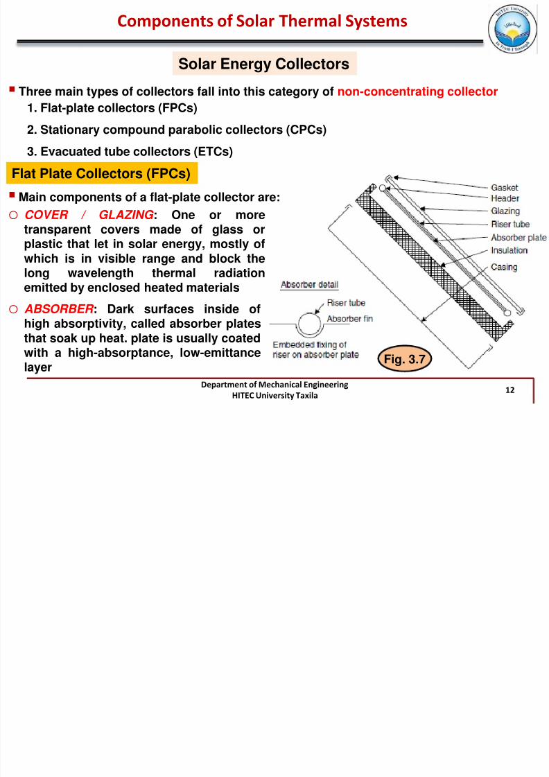
Three main types of collectors fall into this category of non-concentrating collector
1. Flat-plate collectors (FPCs)
2. Stationary compound parabolic collectors (CPCs)
3. Evacuated tube collectors (ETCs)
Flat Plate Collectors (FPCs)
Main components of a flat-plate collector are:
o COVER / GLAZING : One or moretransparent covers made of glass orplastic that let in solar energy, mostly ofwhich is in visible range and block thelong wavelength thermal radiation
emitted by enclosed heated materials
o ABSORBER : Dark surfaces inside ofhigh absorptivity, called absorber platesthat soak up heat. plate is usually coatedwith a high-absorptance, low-emittancelayer
Fig. 3.7

7/29/2019 Chap3 STS Till 29-Nov12
http://slidepdf.com/reader/full/chap3-sts-till-29-nov12 13/52
Department of Mechanical EngineeringHITEC University Taxila
13
Solar Energy Collectors
Components of Solar Thermal Systems
o
INSULATION: material at the back andsides of the collector box to preventconduction heat losses from the backand sides to the environment
o FLUID PASSAGEWAYS: Vents or pipes
connected to or integrated into theabsorber plates to carry the heatedfluid to where it can be stored or used
o CONTAINER: The casing surroundsthe aforementioned componentsand protects them from dust,
moisture, and any other material
Fig. 3.7

7/29/2019 Chap3 STS Till 29-Nov12
http://slidepdf.com/reader/full/chap3-sts-till-29-nov12 14/52
Department of Mechanical EngineeringHITEC University Taxila
14
When solar radiation passes
through a transparent cover
and impinges on the
blackened absorber surface ofhigh absorptivity, a large
portion of this energy is
absorbed by the plate and
transferred to the transportmedium in the fluid tubes, to
be carried away for storage or
use
Glazing
Casing
Back and side
Insulation Absorber Plate with
Selective Coating
Incident radiation
(visible range)
Emitted radiation by absorber (Infrared range)
Heat Loss to Ambient
Reflection
Fluid Carrying
passage
Solar Energy Collectors
Components of Solar Thermal Systems
Flat Plate Collectors (FPCs)—contd--
Fig. 3.8

7/29/2019 Chap3 STS Till 29-Nov12
http://slidepdf.com/reader/full/chap3-sts-till-29-nov12 15/52
Department of Mechanical EngineeringHITEC University Taxila
15
Solar Energy Collectors
Components of Solar Thermal Systems
Flat Plate Collectors (FPCs)—contd--
Liquid tubes can be welded to the absorbing plate or they can be an integral part of theplate
Liquid tubes are connected at both ends by large-diameter header tubes
HEADER AND RISER COLLECTOR is the typical design for flat-plate collectors
Alternative is the SERPENTINE DESIGN does not present the potential problem of unevenflow distribution in the various riser tubes of the HEADER AND RISER DESIGN
Fig. 3.9

7/29/2019 Chap3 STS Till 29-Nov12
http://slidepdf.com/reader/full/chap3-sts-till-29-nov12 16/52
Department of Mechanical EngineeringHITEC University Taxila
16
Solar Energy Collectors
Components of Solar Thermal Systems
Flat Plate Collectors (FPCs)—contd--
Absorber plate can be a single sheet on which all risers are fixed, or each riser can befixed on a separate fin
Transparent cover is used to reduce convection losses from the absorber plate throughthe restraint of the stagnant air layer between the absorber plate and the glass
Fig. 3.10
7/29/2019 Chap3 STS Till 29-Nov12
http://slidepdf.com/reader/full/chap3-sts-till-29-nov12 17/52
Department of Mechanical EngineeringHITEC University Taxila
17
Solar Energy Collectors
Components of Solar Thermal Systems
Flat Plate Collectors (FPCs) — contd--
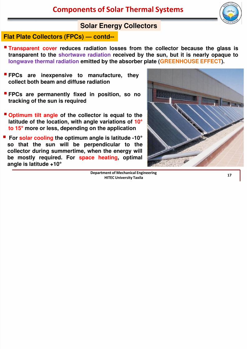
Transparent cover reduces radiation losses from the collector because the glass istransparent to the shortwave radiation received by the sun, but it is nearly opaque tolongwave thermal radiation emitted by the absorber plate (GREENHOUSE EFFECT).
FPCs are inexpensive to manufacture, theycollect both beam and diffuse radiation
FPCs are permanently fixed in position, so notracking of the sun is required
Optimum tilt angle of the collector is equal to thelatitude of the location, with angle variations of 10°
to 15° more or less, depending on the application For solar cooling the optimum angle is latitude -10°
so that the sun will be perpendicular to thecollector during summertime, when the energy willbe mostly required. For space heating, optimalangle is latitude +10°

7/29/2019 Chap3 STS Till 29-Nov12
http://slidepdf.com/reader/full/chap3-sts-till-29-nov12 18/52
Department of Mechanical EngineeringHITEC University Taxila
18
Solar Energy Collectors
Components of Solar Thermal Systems
Flat Plate Collectors (FPCs) — contd--
Collector should also have a long effective life, despite the adverse effects of the sun’s ultraviolet radiation and corrosion and clogging because of acidity, alkalinity, or hardness of the heat transfer fluid, freezing of water, or deposition of dust or moisture on theglazing and breakage of the glazing from thermal expansion, hail, vandalism, or othercauses
Glazing Materials
Requirements for the transparent cover are:
ohigh light transmittance during the whole service life of the collector
o low reflection
o protection from the cooling effects of the wind and convection
o protection from moisture
o stability with regard to mechanical loads (hailstones, broken branches etc.).

7/29/2019 Chap3 STS Till 29-Nov12
http://slidepdf.com/reader/full/chap3-sts-till-29-nov12 19/52
Department of Mechanical EngineeringHITEC University Taxila
19
Solar Energy Collectors
Components of Solar Thermal Systems
Flat Plate Collectors (FPCs) — contd--
Glazing Materials—contd--
Glass has been widely used to glaze solar collectors
Glass transmit as much as 90% of the incoming shortwave solar irradiation whiletransmitting virtually none of the longwave radiation emitted outward by the absorberplate
Glass with low iron content has a relatively high transmittance for solar radiation(approximately 0.85 –0.90 at normal incidence), but its transmittance is essentially zero forthe longwave thermal radiation (5.0 –50 μm) emitted by sun-heated surfaces
For direct radiation, transmittance of glass varies considerably with the angle of incidence
Antireflective coatings and surface texture can improve transmission significantly. The
effect of dirt and dust on collector glazing may be quite small
Plastic films and sheets also possess high shortwave transmittance
Most usable varieties also have transmission bands in the middle of the thermal radiationspectrum, they may have long wave transmittances as high as 0.40

7/29/2019 Chap3 STS Till 29-Nov12
http://slidepdf.com/reader/full/chap3-sts-till-29-nov12 20/52
Department of Mechanical EngineeringHITEC University Taxila
20
Only a few types of plastics can withstand the sun’s ultraviolet radiation for long periods
Plastics are generally limited in the temperatures they can sustain without deteriorating or
undergoing dimensional changes
Solar Energy Collectors
Flat Plate Collectors (FPCs) — contd--
Glazing Materials—contd--
Plastics are not broken by hail or stones, and in the form of thin films, they are completelyflexible and have low mass
ABSORBER
Core piece of a glazed flat-plate collector
Consists of a heat conducting metal sheet with a dark coating
When the solar radiation hits the absorber it is mainly absorbed and partially reflected
It consists of a heat conducting metal sheet with a dark coating
Heat is created through the absorption and conducted in the metal sheet to the heattransfer medium tubes or channels
Components of Solar Thermal Systems

7/29/2019 Chap3 STS Till 29-Nov12
http://slidepdf.com/reader/full/chap3-sts-till-29-nov12 21/52
Department of Mechanical EngineeringHITEC University Taxila
21
Solar Energy Collectors
ABSORBER — contd--
Components of Solar Thermal Systems
Flat Plate Collectors (FPCs) — contd--
To maximize the energy collection, the absorber of a collector should have a coating thathas high absorptance for solar radiation (short wavelength) and a low emittance for re-radiation (long wavelength) → Such a surface is referred as a SELECTIVE SURFACE
Copper Sheet Black Paint Black Chrome TINOX
By suitable electrolytic or chemical treatment, surfaces can be produced with high valuesof solar radiation absorptance (α) and low values of longwave emittance (ε)
Selective surfaces are particularly important when the collector surface temperature ismuch higher than the ambient air temperature
Fig. 3.11

7/29/2019 Chap3 STS Till 29-Nov12
http://slidepdf.com/reader/full/chap3-sts-till-29-nov12 22/52
Department of Mechanical EngineeringHITEC University Taxila
22
Flow passages
Solar Energy Collectors
Components of Solar Thermal Systems
Flat Plate Collectors (FPCs) — contd--
For fluid-heating collectors, passages must be integral with or firmly bonded to theabsorber plate
Materials most frequently used forcollector plates are copper,aluminum, and stainless steel
If the working fluid is a liquid , theflow passage is usually a tube that isattached to or is a part of absorberplate. If the working fluid is air , theflow passage should be below theabsorber plate to minimize heatlosses
Further Details-Self StudyPages: 127-129, PDF: Solar Collectors
Fig. 3.12

7/29/2019 Chap3 STS Till 29-Nov12
http://slidepdf.com/reader/full/chap3-sts-till-29-nov12 23/52
Department of Mechanical EngineeringHITEC University Taxila
23
Solar Energy Collectors
Components of Solar Thermal Systems
Flat Plate Collectors (FPCs) — contd – Special Designs
Integrated Collector Storage (ICS) or Batch Collectors
Collector and water store form a construction unit
components omitted are:oHeat exchanger,opiping for the solar circuit,ocontroller and circulation pump
heat water in dark tanks or tubes within aninsulated box, storing water until drawn.
It is a self-contained Integration of solar Collectorand solar heated water Storage
ICS systems are similar to thermosyphon systemsin that they heat water passively without pumpsand controller systems

7/29/2019 Chap3 STS Till 29-Nov12
http://slidepdf.com/reader/full/chap3-sts-till-29-nov12 24/52
Department of Mechanical EngineeringHITEC University Taxila
24
Solar Energy Collectors
Flat Plate Collectors (FPCs) — contd – Special Designs
Integrated Collector Storage (ICS) or Batch Collectors — contd –
It is prone to freezing, the system mustbe drained in winter months in colderclimates.
Efficiency is also limited in cold weatherand at night due to the significant loss ofheat
A batch solar water heater is somewhatlimited in size, so typically no more thanfour people can benefit from the system
Limitations/Disadvantages:
Components of Solar Thermal Systems

7/29/2019 Chap3 STS Till 29-Nov12
http://slidepdf.com/reader/full/chap3-sts-till-29-nov12 25/52
Department of Mechanical EngineeringHITEC University Taxila
25
Components of Solar Thermal Systems
Solar Energy Collectors
Flat Plate Collectors (FPCs) — contd – Special Designs
Hybrid Collectors
Hybrid collectors are a combination of solar panels (PV) with liquid based collectors aswell as with air-based collectors
combination with solar panels is reasonable, because during the solar electricityconversion only about 12% (with crystalline silicon) of the solar radiation converts into
electricity, whereas the remainder converts into heat. This heat is used in the hybridcollector to either heat up a liquid or air
The central problem with hybrid collectors is the high and in part more persistenttemperature load of the solar cells in the event of stagnation

7/29/2019 Chap3 STS Till 29-Nov12
http://slidepdf.com/reader/full/chap3-sts-till-29-nov12 26/52
Department of Mechanical EngineeringHITEC University Taxila
26
Solar Energy Collectors
Components of Solar Thermal Systems
Compound Parabolic Collectors (CPCs)
CPCs are made up of two parabolicreflectors and an absorber which is placedat the bottom of the collector
(CPC) are usually non-tracking and non-imaging collectors
Compound parabolic concentrators canaccept incoming radiation over a relativelywide range of angles
Fig. 3.13
By using multiple internal reflections, any radiation entering the aperture within the
collector acceptance angle finds its way to the absorber surface located at the bottom ofthe collector

7/29/2019 Chap3 STS Till 29-Nov12
http://slidepdf.com/reader/full/chap3-sts-till-29-nov12 27/52
Department of Mechanical EngineeringHITEC University Taxila
27
The most commonly studied system is adoubled walled concentric glass tube placed at
the focus of a compound parabolic concentrator
Solar Energy Collectors
Components of Solar Thermal Systems
Compound Parabolic Collectors (CPCs)—Contd--
Fig. 3.14
The absorber can take a variety ofconfigurations. It can be flat, bifacial, wedge,or cylindrical
Compound parabolic collectors should have agap between the receiver and the reflector toprevent the reflector from acting as a finconducting heat away from the absorber
For higher-temperature applications a trackingCPC can be used

7/29/2019 Chap3 STS Till 29-Nov12
http://slidepdf.com/reader/full/chap3-sts-till-29-nov12 28/52
Department of Mechanical EngineeringHITEC University Taxila
28
Solar Energy Collectors
Components of Solar Thermal Systems
Compound Parabolic Collectors (CPCs)—Contd--
Compound parabolic collectors can be manufactured either as one unit with one openingand one receiver (see Figure 3.14) or as a panel (see Figure 3.15). When constructed as apanel, the collector looks like a flat-plate collector
Fig. 3.14
T P j
7/29/2019 Chap3 STS Till 29-Nov12
http://slidepdf.com/reader/full/chap3-sts-till-29-nov12 29/52
Department of Mechanical EngineeringHITEC University Taxila
29
Term Project
Project Group Members
Solar Cooking Technology Sidra Akbar
Sadaf Saghir
Solar Drying Technology Imran Sajid Shahid
Usman Manzoor
Saad Malik
Introduction
Historical Background
A brief review of available technologies/methods
oPros and cones of each technology/methodoTechnical Aspects ( Typical Temperatures, heat requirements etc.)
A simple case study (Theoretical design of a system for a certain application
Submission Date: 03-01-2013

7/29/2019 Chap3 STS Till 29-Nov12
http://slidepdf.com/reader/full/chap3-sts-till-29-nov12 30/52
Department of Mechanical EngineeringHITEC University Taxila
30
Solar Energy Collectors
Components of Solar Thermal Systems
Vacuum Collectors
Benefits of simple conventional FPCs are greatly reduced when conditions becomeunfavorable during cold, cloudy, and windy days
Weathering influences, such as condensation and moisture, cause early deterioration ofinternal materials, resulting in reduced performance and system failure
To overcome the above mentioned factors and due to the technical difficulties to evacuatethe space between the absorber and cover in FPC and to withstand the resulting externalpressure, evacuated tube collectors are used
In order to completely suppressthermal losses throughconvection, the volume enclosed
in the glass tubes must beevacuated to less than 10 –2 bar (1kPa)
Additional evacuation (up to 10-6 bar) prevents losses throughthermal conduction
Fig. 3.15
1bar 10-2 bar 10-6 bar
f l h l

7/29/2019 Chap3 STS Till 29-Nov12
http://slidepdf.com/reader/full/chap3-sts-till-29-nov12 31/52
Department of Mechanical EngineeringHITEC University Taxila
31
Radiation losses cannot be reduced by creating a vacuum, as no medium is necessary forthe transport of radiation. They are kept low, as in the case of glazed flat-plate collectors,by selective coatings (small ε-value).
Solar Energy Collectors
Components of Solar Thermal Systems
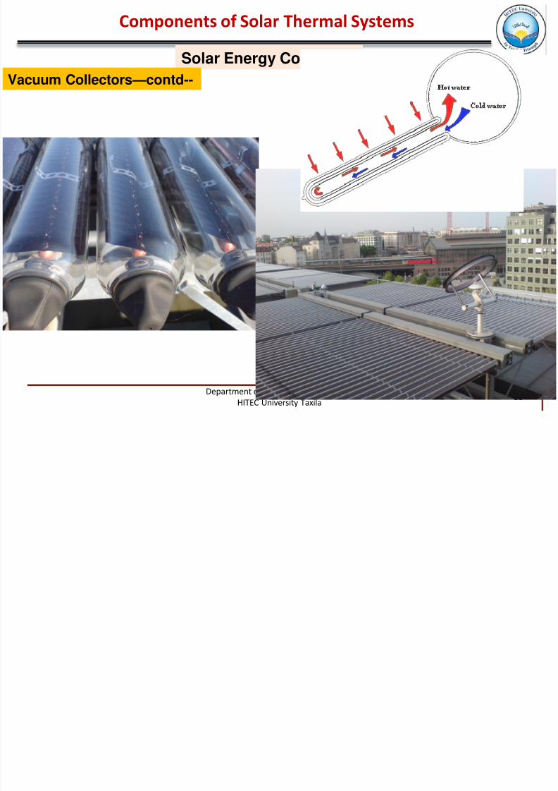
Vacuum Collectors—contd--
absorber is installed as either flat or upward-vaulted metal strips or as a coating applied toan internal glass bulb in an evacuated glass tube
An evacuated tube collector consists of a number oftubes that are connected together and which arelinked at the top by an insulated distributor orcollector box, in which the feed or return lines run.
There are two main sorts of evacuated tube collector:the Direct Flow-through Type and the Heat-pipe Type.
C f S l h l S

7/29/2019 Chap3 STS Till 29-Nov12
http://slidepdf.com/reader/full/chap3-sts-till-29-nov12 32/52
Department of Mechanical EngineeringHITEC University Taxila
32
b) Absorber: flat, metal with coating. Passage: metal U-pipe
a) Absorber: flat, metal with coating. Passage: metal coaxial pipe
Glass
Absorber
Glass
Absorber
Glass
Absorber
c) Absorber: flat, metal with coating. Passage: metal, circular pipe straight through g) Absorber: cylindrical, metal with coating. Passage: metal U-pipe
Glass
Absorber
f) Absorber: cylindrical, glass with coating. Passage:
glass coaxial pipe
Glass
Absorber
e) Absorber: cylindrical, glass with coating. Passage: glass
Glass
Absorber
Schematic diagrams of different configurations of directflow type evacuated tube collectors
Solar Energy Collectors
Components of Solar Thermal Systems
Vacuum Collectors—contd--
Fig. 3.16
C f S l Th l S
7/29/2019 Chap3 STS Till 29-Nov12
http://slidepdf.com/reader/full/chap3-sts-till-29-nov12 33/52
Department of Mechanical EngineeringHITEC University Taxila
33
Solar Energy Collectors
Components of Solar Thermal Systems
Vacuum Collectors—contd--
C t f S l Th l S t

7/29/2019 Chap3 STS Till 29-Nov12
http://slidepdf.com/reader/full/chap3-sts-till-29-nov12 34/52
Department of Mechanical EngineeringHITEC University Taxila
34
Solar Energy Collectors
Components of Solar Thermal Systems
Vacuum Collectors—contd--
Sydney collector
A particular design of direct flow-through evacuated tubecollector marketed in some countries is the Sydney collector
Collector tube consists of:
o
vacuum-sealed double tubeoinner glass bulb is provided with a
selective coating of a metal carboncompound on a copper base
oInto this evacuated double tube isplugged a thermal conducting plate
in connection with a U-tube to whichthe heat is transferred.
To increase the radiation gain thecollector is fitted with externalreflectors in the sloping roof version Fig. 3.17
C t f S l Th l S t
7/29/2019 Chap3 STS Till 29-Nov12
http://slidepdf.com/reader/full/chap3-sts-till-29-nov12 35/52
Department of Mechanical EngineeringHITEC University Taxila
35
Solar Energy Collectors
Components of Solar Thermal Systems
Vacuum Collectors—contd--
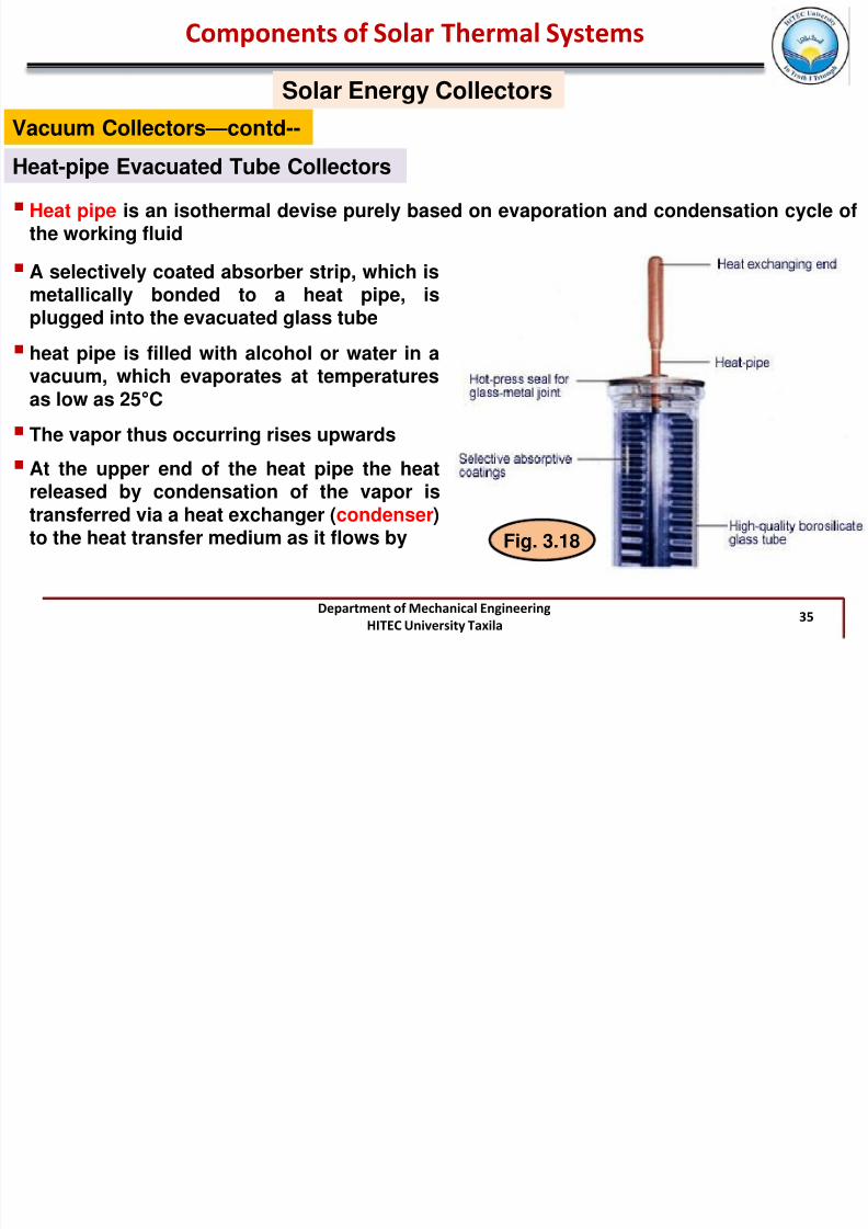
Heat-pipe Evacuated Tube Collectors
Heat pipe is an isothermal devise purely based on evaporation and condensation cycle ofthe working fluid
A selectively coated absorber strip, which ismetallically bonded to a heat pipe, isplugged into the evacuated glass tube
heat pipe is filled with alcohol or water in avacuum, which evaporates at temperaturesas low as 25°C
The vapor thus occurring rises upwards
At the upper end of the heat pipe the heatreleased by condensation of the vapor istransferred via a heat exchanger (condenser)to the heat transfer medium as it flows by Fig. 3.18
C t f S l Th l S t

7/29/2019 Chap3 STS Till 29-Nov12
http://slidepdf.com/reader/full/chap3-sts-till-29-nov12 36/52
Department of Mechanical EngineeringHITEC University Taxila
36
Solar Energy Collectors
Components of Solar Thermal Systems
Vacuum Collectors—contd--
Heat-pipe Evacuated Tube Collectors—contd--
The condensate flows back down into the heat pipe to take up the heat again
For appropriate functioning of the tubes they must be installed at a minimum slope of 25°
Fig. 3.19
C t f S l Th l S t
7/29/2019 Chap3 STS Till 29-Nov12
http://slidepdf.com/reader/full/chap3-sts-till-29-nov12 37/52
Department of Mechanical EngineeringHITEC University Taxila
37
Solar Energy Collectors
Components of Solar Thermal Systems
Vacuum Collectors—contd--
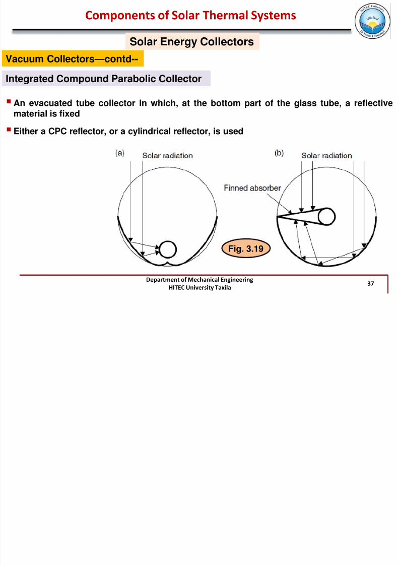
Integrated Compound Parabolic Collector
An evacuated tube collector in which, at the bottom part of the glass tube, a reflectivematerial is fixed
Either a CPC reflector, or a cylindrical reflector, is used
Fig. 3.19
Components of Solar Thermal Systems
7/29/2019 Chap3 STS Till 29-Nov12
http://slidepdf.com/reader/full/chap3-sts-till-29-nov12 38/52
Department of Mechanical EngineeringHITEC University Taxila
38
Solar Energy Collectors
Components of Solar Thermal Systems
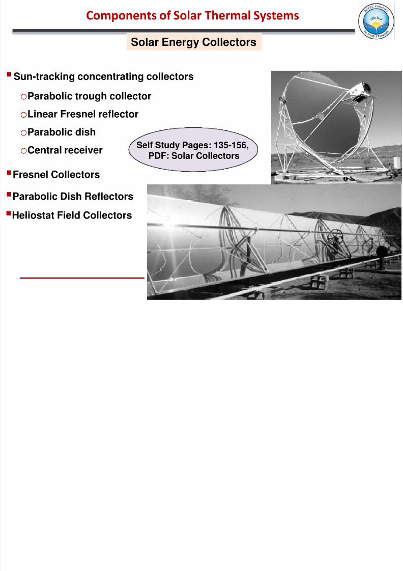
oParabolic trough collector
oLinear Fresnel reflector
oParabolic dish
oCentral receiver
Sun-tracking concentrating collectors
Fresnel Collectors
Parabolic Dish Reflectors
Heliostat Field Collectors
Self Study Pages: 135-156,PDF: Solar Collectors
Components of Solar Thermal Systems

7/29/2019 Chap3 STS Till 29-Nov12
http://slidepdf.com/reader/full/chap3-sts-till-29-nov12 39/52
Department of Mechanical EngineeringHITEC University Taxila
39
Solar Energy Collectors
Components of Solar Thermal Systems
Stagnation temperature
Stagnation Temperature is the temperature at a stagnation point in a fluid flow
oIf the circulation pump fails in the event of strong solar irradiance,
oAbsorber heats up until the heat losses through convection, heat radiation and heatconduction reach the thermal output of the absorber
oor if – for example in holiday times – no hot water is used so that the store is hot (60 –90°C; 140 –194°F) and the system switches off, no more heat is drawn from thecollector
Well-insulated Glazed Flat-plate Collectors achieve maximum stagnation temperatures of160 –200°C (320 –392°F) --- Evacuated Tube Collectors 200 –300°C (392 –572°F) or with areflector – as much as 350°C (662°F)
For Solar collectors STAGNATION CONDITIONS are considered to be any situation underwhich the solar collector can not adequately reject absorbed solar heat to its primaryheat transfer fluid, thereby resulting in the solar collector and/or its components(including the heat-transfer fluid contained within its flow passages) to increase in
temperature above a desired maximum level
Components of Solar Thermal Systems

7/29/2019 Chap3 STS Till 29-Nov12
http://slidepdf.com/reader/full/chap3-sts-till-29-nov12 40/52
Department of Mechanical EngineeringHITEC University Taxila
40
Such extreme stagnation conditions lead to:o deterioration of collector materials, like loss of vacuum in ETCs (evacuated tube
collectors) de to out-gassing from collector materials,oheat transfer fluid may rapidly degrade or even boil,oexcessive pressures may occur in the solar collector heat-transfer loop
Solar Energy Collectors
Components of Solar Thermal Systems
Stagnation temperature—contd--
Heat Storage
Energy storage in solar thermal applications is necessary, whenever there is mismatchbetween the available solar radiation and demand---Because of the seasonal, diurnal andintermittent nature of solar radiation
Optimum capacity of an storage system depends on:
o the expected time dependence of solar radiation availabilityo the nature of loads to be expected on the processo The manner in which auxiliary energy suppliedo An Economic analysis that determines how much of the load should be carried by
solar and how much by the auxiliary energy source
Components of Solar Thermal Systems

7/29/2019 Chap3 STS Till 29-Nov12
http://slidepdf.com/reader/full/chap3-sts-till-29-nov12 41/52
Department of Mechanical EngineeringHITEC University Taxila
41
Components of Solar Thermal Systems
Heat Storage
Process Loads and Solar Collector Outputs
Further details: Pages:382-384,
Book: by Duffie and Beckmann
G T, Q u and L as a function of time for 3-day period
Energy added to or removed from storage
Integrated values of the G T, Q u and L for the same 3 day period
GT: Available Solar Radiation
Qu: Useful Heat GainL: LoadsLA: Auxiliary energy supplied
A major objective of thesystem’s performance
analysis is to find long-termvalues of LA ,i.e amount ofenergy that must bepurchased
Times of excess energy
Energy withdrawn
from the storage
Components of Solar Thermal Systems

7/29/2019 Chap3 STS Till 29-Nov12
http://slidepdf.com/reader/full/chap3-sts-till-29-nov12 42/52
Department of Mechanical EngineeringHITEC University Taxila
42
Components of Solar Thermal Systems
Heat Storage
Types of Thermal Energy Storage
Sensible-Heat Storage
Sensible heat Q is stored in a material of mass m and specific heat C p by rising thetemperature of the storage material from T 1 to T 2 and is :
2
1
2
1
T T
T
p
T
p dT VcdT mcQ
Most Common sensible heat storage materials are water, organic oils, rocks, ceramics,and molten salt----Water has the highest specific heat value of 4190 J/kg. C
Most common medium for storing sensibleheat for use with low and mediumtemperature solar systems is Water---it’s cheap and abundant
Water is the standard storage medium for solar-heating and cooling systems for buildingstoday
Components of Solar Thermal Systems

7/29/2019 Chap3 STS Till 29-Nov12
http://slidepdf.com/reader/full/chap3-sts-till-29-nov12 43/52
Department of Mechanical EngineeringHITEC University Taxila
43
Components of Solar Thermal Systems
Heat Storage
Types of Thermal Energy Storage—contd--
Sensible-Heat Storage—contd--
)()()('
.
asssu
s
s p T T UA LQdt
dT
mC
)]()([)(
'
asssu
s p
ssT T UA LQ
mC
t T T
An energy balance on the unstratified storage tank ofmass m operating at time-dependent temperature T s in ambient temperature T a
’
• Q u Rate of addition or removal of energy from the collector• Ls Rate of addition or removal of energy from the load and
• T a ’ Ambient temperature for the tank (which could be different from that of collector)
3.1
3.2
Eq. (3.1) is to be integrated over time to determine the long term performance of the
storage unit and the solar processUsing Euler integration (i.e. rewriting the temp derivative as [(T s
+ - T s ) /∆t] and solving forthe tank temperature at the end of time increment:
Components of Solar Thermal Systems

7/29/2019 Chap3 STS Till 29-Nov12
http://slidepdf.com/reader/full/chap3-sts-till-29-nov12 44/52
Department of Mechanical EngineeringHITEC University Taxila
44
Components of Solar Thermal Systems
Heat Storage
Types of Thermal Energy Storage—contd--
Sensible-Heat Storage—contd--
)]()([)(
'
asssu
s p
ssT T UA LQ
mC
t T T
3.2
Temperature at the end of an hour is calculated from that at the beginning, assuming Q u ,
Ls , and the tank losses do not change during that hour
Terms in Eq. (3.1) are rates and in Eq. (3.2), they are integrated quantities over an hour
Once the tank temperature T s is know, other temperature dependent quantities can beestimated
Solutions to the governing system equations when integrated over long periods (usually a
year) provide information on how much solar energy is delivered to meet load.
Components of Solar Thermal Systems

7/29/2019 Chap3 STS Till 29-Nov12
http://slidepdf.com/reader/full/chap3-sts-till-29-nov12 45/52
Department of Mechanical EngineeringHITEC University Taxila
45
Components of Solar Thermal Systems
Heat Storage
Types of Thermal Energy Storage—contd--
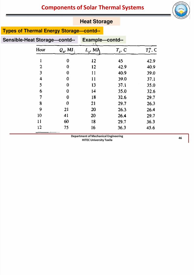
Sensible-Heat Storage—contd-- Example
A fully mixed water tank storage containing 1500 kg of
water has a loss coefficient area product of 11.1 W/oC
and is located in a room at 20 oC. At the beginning of a
particular hour the tank temperature is 45 oC. During the
hour energy Qu is added to the tank from a solar
collector, and energy Ls is removed from the tank and
delivered to a load as indicated in the table. Using Euler
integration, calculate the temperature of the tank at the
end of each of 12 hours.
)]()([)(
'
asssu
s p
ssT T UA LQ
mC
t T T
Components of Solar Thermal Systems
7/29/2019 Chap3 STS Till 29-Nov12
http://slidepdf.com/reader/full/chap3-sts-till-29-nov12 46/52
Department of Mechanical EngineeringHITEC University Taxila
46
Components of Solar Thermal Systems
Heat Storage
Types of Thermal Energy Storage—contd--
Sensible-Heat Storage—contd-- Example—contd--
Components of Solar Thermal Systems

7/29/2019 Chap3 STS Till 29-Nov12
http://slidepdf.com/reader/full/chap3-sts-till-29-nov12 47/52
Department of Mechanical EngineeringHITEC University Taxila 47
Components of Solar Thermal Systems
Heat Storage
Types of Thermal Energy Storage—contd--
Sensible-Heat Storage—contd--
Narrowness of the Hot Water Store
A general schematic of the Upright modelsolar tank with auxiliary heat exchanger isshown
Hot waterextraction
Heating feed(Auxiliary)
Heating Return(Auxiliary)
Solar CircuitFeed
Solar CircuitReturn
Cold WaterSupply
Every time a tap is turned on, cold waterflows into the lower area of the store, →
cold, warm and hot water are found in theone store at the same time
Because of the different densities, a
Temperature Stratification effect forms,‘lighter’ hot water collects at the top, the‘heavier’ cold water in the lower tank area
Stratification Effect has a positive effect onthe efficiency of a solar system
Components of Solar Thermal Systems

7/29/2019 Chap3 STS Till 29-Nov12
http://slidepdf.com/reader/full/chap3-sts-till-29-nov12 48/52
Department of Mechanical EngineeringHITEC University Taxila 48
Components of Solar Thermal Systems
Heat Storage
Types of Thermal Energy Storage—contd--
Sensible-Heat Storage—contd-- Narrowness of the Hot Water Store
As soon as hot water is drawn off, cold water flows in: thisshould not mix with the hot water. The slimmer and taller thestore, the more pronounced the temperature stratification will be
Upright stores have the best stratification; the recommendedheight –diameter ratio for optimum stratification is at least 2.5:1
Coldest possible lower zone ensuresthat, even with low irradiance, the solarsystem can still operate with highefficiency at a low temperature level
Stable Stratification
No stratification, Additional Heat Required
For interested readers:1- Chapter-8, Energy Storage, Book: by
Duffie and Beckmann2- Chapter-2, Book: Planning and
installing Solar Thermal Systems
Components of Solar Thermal Systems

7/29/2019 Chap3 STS Till 29-Nov12
http://slidepdf.com/reader/full/chap3-sts-till-29-nov12 49/52
Department of Mechanical EngineeringHITEC University Taxila 49
Components of Solar Thermal Systems
Heat Storage
Types of Thermal Energy Storage—contd--
Latent Heat Storage
Thermal energy can be stored as latent heat in a material that undergoes phasetransformation at a temperature that is useful for the application
If a material with phase change temp. T m is heated from T 1 to T 2 such that T 1 < T m < T 2 , the
thermal energy Q stored in a mass m of the material is given by:
3.3 ʎ = heat of phase transformation
Four types of phase transformation useful for latent heat storage are:oSolid ⇌ Liquid
oLiquid⇌ VaporoSolid⇌ Vapor
oSolid⇌ Solid Some common phase change materials (PCMs) used for thermal storage are: Paraffin
waxes, nonparaffins, inorganic salts (both anhydrous and hydrated).
Components of Solar Thermal Systems

7/29/2019 Chap3 STS Till 29-Nov12
http://slidepdf.com/reader/full/chap3-sts-till-29-nov12 50/52
Department of Mechanical EngineeringHITEC University Taxila 50
Components of Solar Thermal Systems
Heat Storage
Types of Thermal Energy Storage—contd-- Latent Heat Storage—contd--
Components of Solar Thermal Systems
7/29/2019 Chap3 STS Till 29-Nov12
http://slidepdf.com/reader/full/chap3-sts-till-29-nov12 51/52
Department of Mechanical EngineeringHITEC University Taxila 51
Components of Solar Thermal Systems
Heat Storage
Types of Thermal Energy Storage—contd--
Thermo Chemical Heat Storage
Heat storage in this mode is based on the Reversible Chemical Reaction according to theformula
A + B⇌ AB + Heat
Reaction in the forward direction is exothermic and endothermic in the reverse direction
Amount of heat stored in a chemical reaction depends on the heat of reaction and theextent of conversion as given by:
a r : fraction reacedm : mass∆H : Heat of reaction per unit mass
3.4
During the load phase, the substance AB is supplied with heat, which dissociates thecomponents A and B
In order to recover the heat, both components A and B are allowed to react with one other
As long as a reaction between A and B is prevented, the heat stored in form of chemicalenergy cannot be set free
Components of Solar Thermal Systems
7/29/2019 Chap3 STS Till 29-Nov12
http://slidepdf.com/reader/full/chap3-sts-till-29-nov12 52/52
Components of Solar Thermal Systems
Heat Storage
Types of Thermal Energy Storage—contd--
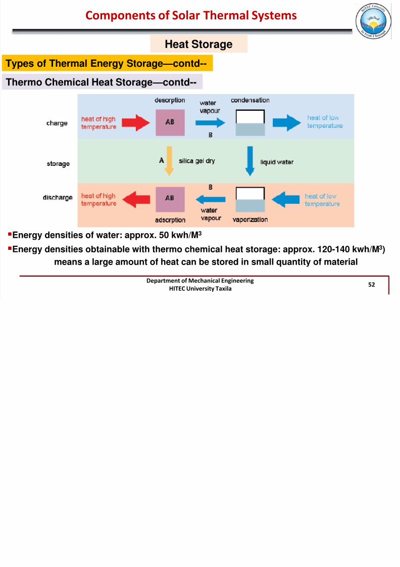
Thermo Chemical Heat Storage—contd--
Energy densities of water: approx. 50 kwh/M3
Energy densities obtainable with thermo chemical heat storage: approx. 120-140 kwh/M3)
means a large amount of heat can be stored in small quantity of material