comparing commercial engineering program for dcs-systems
TRANSCRIPT

Comparing commercial engineering program for DCS-systems
Bachelor's Thesis
HAMK Valkeakoski, Electrical and Automation Engineering
Spring, 2019
Juha Heino

1
ABSTRACT Sähkö- ja automaatiotekniikka Valkeakoski Author Juha Heino Year 2019 Title Comparing commercial engineering program for DCS-
systems Supervisor(s) Juha Sarkula
TIIVISTELMÄ
Opinnäytetyön tilaaja on Valmet Automation. Tässä opinnäytetyössä valitaan aluksi kolme sähkösuunnitteluun tarkoitettua ohjelmaa ja niitä vertaillaan toisiinsa ohjelmista löytyvien tietojen perusteella. Myös suunnitteluun vaikuttaviin standardeihin perehdytään ja raportoidaan niistä oleellisimmat kohdat. Työssä päädyttiin valitsemaan CADS, E3 ja EPLAN tarkasteltaviksi ohjelmiksi. Millä tahansa näistä ohjelmalla suunnittelu voitaisiin toteuttaa laadukkaasti, sekä kustannustehokkaasti. Työn ensimmäisessä vaiheessa tutkitaan ohjelmia näistä löytyvien ohjeiden avulla, sekä internetistä löytyvien tietojen perusteella. Ensimmäisen vaiheen tutkimuksien perusteella E3 ohjelma tiputettiin pois jatkotutkimuksista rajallisen ajan ja resurssien takia. Toisessa vaiheessa osallistutaan molempien ohjelmien teknillisen tuen järjestämälle koulutuksille. Koulutuksen avulla saadaan parempi käsitys ohjelmien toiminnasta ja niiden soveltuvuudesta Valmet Automationin automaatiojärjestelmä kaappien suunnitteluun. Kolmannessa vaiheessa verrataan EPLANIa ja CADSia kaikkien projektin aikana kerättyjen tietojen ja kokemusten perusteella. Tutkielman lopuksi valittiin EPLAN ohjelma, koska sen avulla Valmet Automation saavuttaisi kaikista eniten hyötyä ja saisi tehostettua suunnitteluun käytettyä aikaa.
Avainsanat CADS, EPLAN, sähkösuunnittelu Sivut 46 sivua
2
ABSTRACT Electrical and Automation Engineering Valkeakoski Author Juha Heino Year 2019 Subject Comparing commercial engineering program for DCS-
systems Supervisor(s) Juha Sarkula ABSTRACT
This thesis was commissioned by Valmet Automation. For this thesis I chose three commercial electrical engineering programs and compare these programs with the information catered from manuals and the internet. Also, information about the standard that influences engineering is examined and reported the on this thesis. The following three programs were selected to be analysed in this thesis: CADS, E3 and EPLAN. With all of them programs engineering can be done with good quality and the basic functions there are quite the same. In the first phase of this thesis project information was gathered on the programs. This information was gathered from programs manuals and internet web pages. After the first stage E3 programs was dropped from further analyses, because of limited time and resources. The second phase was to take a part of both programs basic training. The trainings target was to get a better knowledge of the program and get an better understanding of how they would fit for engineering Valmet Automations automation systems cabinet. In the last part of this thesis project, EPLAN and CADS are compared to the information that was gathered from manuals and the internet, but also to the practical experience knowledge that has been gained from training.
Keywords EPLAN, CADS, Electrical engineering Pages 46 pages

3
CONTENTS
1 INTRODUCTION ........................................................................................................... 8
1.1 Introduction of company .................................................................................... 8
1.2 Background .......................................................................................................... 9
1.3 Reasons for the project ....................................................................................... 9
1.4 Motivations behind this thesis ............................................................................ 9
1.5 Steps in project .................................................................................................. 10
2 ELECTRICAL ENGINEERING AND DOCUMENTATION ................................................. 11
2.1 Layout ................................................................................................................ 11
2.2 Schematics ......................................................................................................... 13
2.3 Part list (BOM = Bill of Material) ....................................................................... 14
2.4 Computer Aided Design .................................................................................... 15
3 STANDARTDS APPLIED TO ELECTRICAL DOCUMENTATION ...................................... 17
3.1 Documentation ................................................................................................. 17
3.2 Schematics ......................................................................................................... 19
3.2.1 Graphical symbol for schematics ........................................................... 21
3.2.2 Reference designations ......................................................................... 22
3.3 Drawings ............................................................................................................ 23
3.4 Tables ................................................................................................................ 24
3.5 Charts and graphs ............................................................................................. 25
4 COMMERCIAL PROGRAMS ........................................................................................ 27
4.1 CADS .................................................................................................................. 27
4.1.1 Cads Electric ........................................................................................... 27
4.1.2 CADS Electrical Pro ................................................................................ 28
4.1.3 CADS database ....................................................................................... 28
4.1.4 CADS Layout........................................................................................... 30
4.1.5 CADS DM ................................................................................................ 31
4.1.6 CADS links and supported files .............................................................. 31
4.2 EPLAN Introduction ........................................................................................... 31
4.2.1 Electrical P8 ........................................................................................... 32
4.2.2 Pro Panel ................................................................................................ 33
4.2.3 Data Portal ............................................................................................. 34
4.2.4 Basic Projects ......................................................................................... 36
4.2.5 Symbols .................................................................................................. 36
4.2.6 Auto connecting .................................................................................... 36
4.2.7 Automatic Cross-reference.................................................................... 37
4.2.8 Macros ................................................................................................... 37
4.2.9 Reports .................................................................................................. 37
4.2.10 Single- & Multi-Line ............................................................................... 37
4.2.11 Revision Management ........................................................................... 38
4.2.12 Schematic .............................................................................................. 38
4.2.13 Multi-user in EPLAN ............................................................................... 38
4.2.14 User Rights Management ...................................................................... 38

4
4.3 E3 ....................................................................................................................... 38
4.3.1 E3 License .............................................................................................. 39
4.3.2 E3-schematic.......................................................................................... 40
4.3.3 E3-cable module .................................................................................... 40
4.3.4 E3-panel ................................................................................................. 40
4.3.5 E3 Revision management ...................................................................... 40
4.3.6 E3 link to machines ................................................................................ 41
4.3.7 E3 Reports .............................................................................................. 41
4.4 Conclusion of programs after introduction ...................................................... 41
5 FURTHER ANALYSIS BETWEEN EPLAN AND CADS PROGRAMS ................................. 42
5.1 EPLAN ................................................................................................................ 42
5.1.1 EPLAN Basic Training ............................................................................. 42
5.2 CADS .................................................................................................................. 45
5.2.1 CADS Electric Lite Basics Training .......................................................... 45
5.2.2 CADS Industrial engineering training Basic ........................................... 46
5.2.3 CADS Industrial engineering training Pro .............................................. 47
6 FINAL CONCLUSIONS OF PROGRAMS ........................................................................ 49
6.1 Market share ..................................................................................................... 49
6.2 Layout engineering ............................................................................................ 50
6.3 Schematics ......................................................................................................... 51
6.4 Other issues ....................................................................................................... 51
6.5 Criteria and how they were met by programs .................................................. 51
6.6 Conclusions........................................................................................................ 52
6.7 Recommendations for future development ..................................................... 52
7 CONCLUSION OF PROJECT ......................................................................................... 54
REFERENCES .................................................................................................................... 55
5 LIST OF FIGURES Figure 1 2D cabinet outside layout Figure 2 2D cabinets inside layout Figure 3 Main diagram of an automation system cabinet Figure 4 Symbols pin. Figure 5 Bill of Material Figure 6 How the text are lined. (SFS-EN-61082-1/2006, p 33) Figure 7 Document identifier and page numbering example. (SFS-EN-61082-
1/2006, p 35) Figure 8 Different types of cross-reference point in same document. (SFS-EN-
61082-1/2006, p 45) Figure 9 Figure show different types of line connections. (SFS-EN-61082-1/2006, p
69) Figure 10 Avoiding cross-overs (SFS-EN-61082-1/2006, p 73) Figure 11 Single- and multi-line schematic. (SFS-EN-61082-1/2006, p 93) Figure 12 How location base identifier is produced. (SFS-EN-61082-1/2006, p 59) Figure 13 MMJ cable core identifying. (Finnparttia n.d) Figure 14 MMO cable core identifying (Sähkönumerot.fi n.d.) Figure 15 Drawing of a cabinet back plate with parts. (SFS-EN-61082-1/2006, p 145) Figure 16 CADS database links to different documents types. (CADS Electric 17 n.d) Figure 17 CADS I/O modules. Figure 18 2D field automation cabinets layout. Figure 19 Performance Description EPLAN Electric P8 (EPLAN, 2016, p.13) Figure 20 Pro Panel engineering view. (EPLAN, 2016, p.15) Figure 21 Pro Panels auto wiring feature. (EPLAN 2018) Figure 22 Diagram of EPLAN Data Portal users. (EPLAN Data Portal - digital device data now available in DXF-format n.d) Figure 23 EPLAN Data Portals graphical interface. (EPLAN 2015) Figure 24 Picture shows how all E3 modules are connected to getter. (CAD vs CEW
vs CAM: What is the difference? n.d. p2.) Figure 25 Schematic with CADS Figure 26 CADS and ATON communicates both ways. (CADSiin tulossa PDM-
rajapinta n.d)

6 LIST OF TABLES Table 1 How to mark reference point. (SFS-EN-61082-1/2006, p 59) Table 2 Terminal oriental tablet. (SFS-EN-61082-1/2006, p 151) Table 3 Remote end destination. (SFS-EN-61082-1/2006, p 153) Table 4 Time sequence chart. (SFS-EN-61082-1/2006, p 155) Table 5 CAD programs market shares in Finland (CADS Product Suite n.d).

7 LIST OF ABBREVIATIONS BOM Bill of Material CAD Computer Aided Design CAM Computer-Aided Manufacturing CAE Computer-Aided Engineering DPD Digital Product Development ERP Enterprise Resource Planning PDM Product Data Management

8
1 INTRODUCTION
For this thesis I selected three commercial electrical engineering programs and analysed them. The focus is to be analysing three well known programs and comparing them with the gathered information and selecting one program that has the best functions, usability and a global name. In this thesis the financial calculations were left out of judgment as well as the needed licenses, nor was the time it would take to ramp up the programs.
1.1 Introduction of company
Valmet a major developer in technology. It also manufactures the technologies. Valmet has technology for pulp, paper, automation and energy. It’s made their goal to be the global leader in paper and pulp automation. Valmet has 12 000 employees globally and all of them are professionals what they do. Company has local offices to be closer to customers and be committed to their customer. (Valmet yrityksenä, n.d.) Valmet´s services has wide range of services. These services consist of maintenance outsourcing for mill and plants, but also improving these plants and supplying them with spare parts. Valmet has a strong know how in different proses sectors, that include pulp mills, tissues and power plants that includes also bio-energy products. For all of these proses sectors are upgraded with Valmet´s own automation. Valmet´s automation solutions has wide range of measurements from advanced measurements of small specifics processes to hole paper and pulp mills automation systems. (Valmet yrityksenä, n.d.) Valmet has a long history in industrial. This history goes back over 200 years. Valmet was reborn in end of the year 2013, when they demerged from Metso group. In this demerger pulp, paper and power business line brought to Valmet. (Valmet yrityksenä, n.d.) Automation stayed with Metso at this time. Valmet bought automation business line from Metso in January of 2015. With this buy Valmet made their product stronger by being able to delivery hole proses package for mils and plants. (Valmet, 2015) Valmet´s corporate headquarter is in Espoo, Finland. In 2017 it´s net sales were 3.1 billion euros and Valmet are listed in Nasdaq Helsinki. (Valmet yrityksenä, n.d.)

9 1.2 Background
Valmet Automation uses Network Designer programs for hardware and system engineering. This program has some faults, that does not make the engineering efficiency as it could be. Programs does not have project database, so same information must be given to many places/pages. This leaves chance for human error. Network Designer programs is developed by Valmet Automation and this developing has cost. The developing and testing takes one employees full work time. For Network Designer to be more efficient the employee amount must be added by one or two persons. This would add extra cost to programs maintaining and developing. The Network Designer programs is built on top of Microsoft Visio programs, and it utilizes Visio’s diversified design features. Network Designer is a documentation and design tool for designing assembly and layout of the Valmet DNA cabinets and system. In addition to the Visio features, it includes plenty of design enhancing functions and the shapes for Valmet DNA products. Shapes for other products can also be added afterwards. The user can also create shapes. Documents are saved as .vsd or .vsdx files on the disk, in either a project-specific directory on a network disk or a user-specific directory on the local hard disk. Network Designer documents can also be saved in the Valmet DNA engineering database, if the DNA Engineering Server or DNA Engineering Client is installed on the same workstation. (Vuohensilta, n.d.)
1.3 Reasons for the project
Valmet Automations goal is to increase project amount in the near future and this would increase the workload for engineering. By selecting or updating the engineering programs, the engineering time for one project could be reduced. This way more projects could be handled by one engineer. The Network Designer is lacking project database, that could make the engineering more efficiency. Also, with commercial electrical programs there is a possibility of selling Valmet´s hardware to third part engineering companies, that could use parts in their own projects. This would increase the sales of Valmet´s hardware. The cost of Network Designer programs’s developing and maintaining is also one reason why this thesis is done.
1.4 Motivations behind this thesis
The main target of this thesis project was to find one commercial program that had the best qualities and features to make engineering as efficient as possible.

10
To get better efficiency of hardware engineering at Valmet Automation the commercial programs must have a database. This would make engineering faster with better quality. This would increase the efficiency of engineering. Also use of standard in programs symbols and reports are mandatory. With uses of standards, Valmet Automation can make global engineering that are usable in all automation system delivery projects globally. Things that makes the programs quality good are the quality of programs’s symbols and the usability of templates. Programs basic functions and possibility to customise functions if needed. Another demand that was given by Valmet Automation was that the program must be globally well known and have many parts in its programs library. The possibility of adding companies own products to programs part database, so that other companies could use them. The globality of the programs is in a high value in this thesis project. Valmet Automation delivers automation system on a global scale and has many third-party engineering companies working in hardware engineering all over the world.
1.5 Steps in project
The project started with gathering background information about the programs and electrical engineering standards. This was done by reading programs manuals and basic guidelines for electrical engineering. The second phase was to report all information of on the programs. After this introduction report was written, one programs was dropped and the two programs were further analysed. In phase three I attended basic training courses of both programs to get a better knowledge of the use and features of the programs. Last phase is to analyse gathered information from trainings and manuals. The best suitable candidate is selected after this analyse is ready.

11
2 ELECTRICAL ENGINEERING AND DOCUMENTATION
Technical documentation is used to show technical features of the system, part or equipment. This can be done with different styles, but the digital engineering is now days replaced paper engineering. Paper is still used by printing the document to paper, but almost all engineering is done with computers. (Ruuppa & Perkiö, 1996, p.5) Electrical engineering in general is a fast-evolving industry and this gives the engineering its own difficulties. The number of electrical components in one system has grown and come more complex. This means that the documentation has and will grow and gives more demands to documentation. This why Computer Aided Design (CAD) programs has be-come more common. (Ruuppa & Perkiö, 1996, p.10) Technical documentation should contain the following aspects:
The documents should show all needed information clearly and whit no possibility of wrong judgments.
It must be precise and straight forward.
Easy to ready and done with common principles.
Documentation must be easy to update and use. (Ruuppa & Perkiö, 1996, p.10) Electrical engineering has many different aspects, but in this thesis, I will talk about electrical engineering that is done with CAD or CAE programs. Computer has revolutionary engineering work and design. Before what was done with freehand sketches, is now replaced with CAD. This make designing fast and efficient and help reuses of old documents. (Pere & Kivimäki, 1998, p.10) Electrical documents are needed for manufacturing automation system cabinets and for plants maintainer crew. From electrical documents are shown functionality of the automation system cabinets and all electrical connections. When automation system cabinets electrical document is made, it usually contains panel layout in 2D or 3D. In panel layout all components that is needed are shown and the location of them are placed in automation system cabinets. With this document manufacturer can place the parts in correct position. Document has also schematics. In schematics all electrical wiring and connection points are shown.
2.1 Layout
In layout documents the cabinet is shown from the outside with its dimensions. All additional parts like fans and operation panels are shown in this document, like in the example of an automation system cabinet outside layout in Figure 1. It can also show the cut-out dimensions for the

12
fan or operation panel. All parts are shown in the same measurement scale.
Figure 1. 2D cabinet outside layout
The inside of cabinet is showing the backplate where the parts are assembled as in the Figure 2. Component identifiers also need to be shown. A component identifier is the link between the layout document and the schematics.
Figure 2. 2D cabinet inside layout

13
It is very important that all the component identifiers are shown in the layout and that they are correct.
2.2 Schematics
Electrical schematics are drawings that represent the functionality of a product or in this case automation system cabinets. Components are shown in schematics with symbols and the wires that connects components together are lines. Below is an example of a main diagram schematics of a Valmet’s automation system cabinet. With this document the automation system cabinets manufacturer can make all needed connections between components and terminals.
Figure 3. Main diagram of an automation system cabinet
With these symbols and lines, the functionality of the automation system cabinet is shown. Usually in schematics the components size, position or shape is not accurate. The components terminal and pin numbers must be the same as in actual component. Usually components symbols are from standard symbol library. The power supply symbol shown in figure below is from Valmet’s shape library. Symbol has all same terminal connection points as the actual component. This makes it easier for automation system cabinets manufacturers to read schematics.

14
Figure 4. Symbols pin.
By using standard symbols makes it easier to understand schematics and less room for misunderstanding in reading them. All schematics must be transparent and clearly engineered, no room for misunderstanding. Component must have individual identifier. Standard gives a guide how to give these identifiers.
2.3 Part list (BOM = Bill of Material)
From cabinets components it is possible to generate bill of material. This list can be done in few different ways. One would be to list every component to its own row. This way all part identifier could be shown next to the component. Other possibility could be to count all same components to one row. This would be a clear solution and is easier way for manufacturer to count the amount of each component is needed to be ordered. BOM has all the needed information that is needed to purchase the component. These would be components manufacturer, ordering number, quantity and companies own ERP-number. ERP-number is company’s own number for part that could be ordered. Different ordering parts may have the same manufacturing number given by different manufacturers. This could accrue if Phoenix Contact would have given 123456 number for terminal, but also DELL would have given the same

15
exact number for PC. But with ERP-number the company can make each part an individual ordering number and add this to ERP-system.
Figure 5. Bill of Material
In figure above is shown an example of a bill of material. In this first column is shown on what page the part is located. Next column shows how many items of each is needed in this automation system cabinet. Companies ERP-number or if component does not have ERP-number, then the manufacturers number. Next column shows the item name. Next two columns show the manufacturer and manufacturers ordering number. With this information parts to automation system cabinet can be ordered. Part list can also be used by plants maintainer crew to order broken parts and to clarify automation system cabinets schematics.
2.4 Computer Aided Design
CAD programs are used by engineers and designers to create two- or three-dimensional models and layouts of components or cabinets. (Musselwhite, n.d.) Modern CAD programs has many different aspects depending on the professionality of engineer. CAD can be one part of the Digital Product Development (DPD), that can be part of Product Lifecycle Management (PLM). These to getter with other programs can form different programs like:
Computer-Aided Engineering (CAE)
Computer-Aided Manufacturing (CAM)
Photo Realistic Rendering
Document Management and Revision Control using Product Data Management (PDM)

16
Whit the modern CAD programs the design or engineering can be improve the following things:
It can increase efficient of engineering
It can improve the quality of documents and engineering
It can make the documents more readable and with less human errors
It can have database (E3.Series – Electrical Wiring, Control Systems and Fluid Engineering Programs n.d.)

17
3 STANDARTDS APPLIED TO ELECTRICAL DOCUMENTATION
With standards engineering documents can be unified to be made the same way everywhere. Whit standardization it helps users and authorities to understand documents made by companies. With standardization the safety aspect can be lifted, and it makes the global and domestics trade easier. Standards are public documents for everyone to see and use. Use of standards are free, but the documents do cost. (Mitä standardisointi on?, n.d.)
3.1 Documentation
Documentation is an important part of the manufacturing, commissioning and maintenance of a product or system. With good documentation the safety and quality of product or system can be raised. (SFS-EN-61082-1/2006, p 27) Information in documents must be clear and practical. Same information can be shown in many different documents and the information must be the same in all documents. All documents must have document ID, that is an individual code for the document. (SFS-EN-61082-1/2006, p 27) Standard SFS-EN 61082-1 gives rules how the information in documents had to be given. These are text orientation should be done as in figure below. (SFS-EN-61082-1/2006, p 31-33)
Figure 6. Example on how the text are lined. (SFS-EN-61082-1/2006, p 33)
Part identifier is normal manner, but the products terminal numbers are sideways. This applies to all parts that has connection points.

18
Normally all is done in black and colours should only be used as an additional information. If colours are used in documents, the meaning of the colour must be stated in the document. Documents are recommended to be produced in A3 size. But also, other ISO 5457 standards sizes can be used. Documents must have individual identifier. The document group can have a document identifier and inside the document package all pages has their own page number. This way all pages has an individual identifier, that help using documentation. (SFS-EN-61082-1/2006, p 35)
Figure 7. Document identifier and page numbering example. (SFS-EN-61082-1/2006, p 35)
In figure above the document identifier is =AB11&FS and all five pages has the same document identifier. All pages inside of this document package has their own page number, in this case from 1 to 5. (SFS-EN-61082-1/2006, p 43-45) All documents must have at least one header for showing documents metadata. This header should have information about the project, with document identifier, designer, date and revision history. (SFS-EN-61082-1/2006, p 43-45) One important part of good documentation is cross-reference points and the right use of them. There is a couple of ways of doing this, but here is one way introduced.
Reference point: VA200200/6.B4
Document referred to: VA200200
Page in documentation: 6
Zone inside the page: B4 (SFS-EN-61082-1/2006, p.43-45)

19
Figure 8. Different types of cross-reference point in same document. (SFS-EN-61082-1/2006, p 45)
In picture above is shown different ways of using cross-reference in same document. In this case the document identifier is not needed and only page number is shown as it is shown in the first example. In this the line will continue to page three, so the reference point is marked with the number three. And on page three the reference point is two. If the connection on next page is not clear, then also the zone is added to clarified this, as shown in the next two examples. (SFS-EN-61082-1/2006, p.43-45) Standard SFS-EN-61082-1 gives rules for presenting documents in four different basic document types when documents are related to electro-technology.
Schematics
Drawings
Tables
Charts and graphs (ST 13.50/2015, p.1)
3.2 Schematics
SFS-EN 61082-1:2015 section 7.4 states that the schematic documents are used for showing details of the implementation of the product. In schematic the parts and wires are shown, but not taking in facture the parts real size and shape. With schematics the functionality of the product can be shown and helps user to understand the product and how it works. In schematics there are few mandatory things to take in counter when engineering schematics.
Symbols -> Standard
Wiring between symbols
Wire colours

20
Connector identifier
Reference point identifier
Extra information to help user to understand schematic Information about technical information can be added if this in-formation is relevant to schematic. Reference to other documents that are somehow connected to schematic can be added. Wire identifiers and extra information how to connect wire can be added. (ST 13.50/2015, p.1) When drawing a schematic, the connection lines are in an important role in showing the information. The lines must be drawn in a certain matter to give information for manufacturer and user.
Figure 9. Different types of line connections. (SFS-EN-61082-1/2006, p 69)
In figure above is shown the correct way of joining two lines to together. In S01414 and S01415 is shown two physical interconnections is entering same connection point. (SFS-EN-61082-1/2006, p 69) To make schematic clear and easier to understand all cross overs should be avoided. This is shown in figure below.
Figure 10. Avoiding cross-overs (SFS-EN-61082-1/2006, p 73)

21
Schematic can be made in single- or multi-line schematics. The single line is easier to understand but does not give all needed information to connect. (SFS-EN-61082-1/2006, p.72)
Figure 11. Single- and multi-line schematic. (SFS-EN-61082-1/2006, p 93)
In figure above is shown the difference between these two different styles of showing motor connection. In example a) the motor connection is made with multi-line. From this schematic the motor could be connected, because the three-phase connection is shown. But in example b) that is shown in figure above, the schematic only shows that there is three-phase connection. This representing style is single-line. With single-line schematic the phase order is not shown and therefore the connection can’t be made with single-line schematics. (SFS-EN-61082-1/2006, p.93)
3.2.1 Graphical symbol for schematics
The definition of symbol that are used in schematic documents is “a graphical shape to represent information with a universal language”. With shapes the information about the products it self, the functionality of the product and location if it. In IEC 60617 standard are show the international approved shapes for schematics. Product may have multiple shapes, the shape that gives the best information at schematic is chosen. If shape does not give enough information, extra information can be given to clarify schematic. Shapes in schematic are show in rest position that means the relays are shown in position where they are not active. (ST 13.50/2015, p.1-2)

22 3.2.2 Reference designations
According to standard IEC 61346-1 “at least one unambiguous reference designation shall be shown at every representation of the object”. This means that the same identifier is shown in all the symbol that are the same part. The reference can be shown in single line or on successive lines. In this case each reference point will start in its own line. (SFS-EN-61082-1/2006, p.57-61)
Table 1. How to mark reference point. (SFS-EN-61082-1/2006, p 59)
In figure above is shown how the reference identifier is generated from the location and how this is shown in right manner. Other option is to show it as in standard IEC 61346-1 shows the tree-like structure. In this many object can have same partition of the identifier, because this is based on location. (SFS-EN-61082-1/2006, p.57-61)
Figure 12. How location base identifier is produced. (SFS-EN-61082-1/2006, p 59)
Here -A1 could be the identifier of a room. -A1B2 could be the cabinets identifier and the object A-D could be parts inside the cabinet. This way object c that is a part inside the cabinet would be named as the following

23
-A1B2C3. With this system all parts would end up with an individual part identifier. Also, cables must be marked with a unique identifier, but also the core wires must be marked with the numbering or colour that is given by cable manufacturer.
Figure 13. MMJ cable core identifying. (Finnparttia n.d.A)
In figure above is shown the cable core identifiers that uses colour. MMJ cables uses colour coding and with this cable type the cores are marked with the following colour brown, black, grey, blue and green-yellow. Cable identifier and the colour gives a unique identifier.
Figure 14. MMO cable core identifying (Sähkönumerot.fi n.d.)
MMO cables wires are black but marked with numbers as shown in the figure above. Cable identifier and the core number forms a unique identifier.
3.3 Drawings
Drawings are made in 2D- or 3D-models and are used to show topographical or geometrical positions of objects. Base drawing

24
documents are such as site plans, building drawings, dimension drawings that are used in mechanical manufacturing. (SFS-EN-61082-1/2006, p.135)
Figure 15. Drawing of a cabinet back plate with parts. (SFS-EN-61082-1/2006, p 145)
Drawings are normally made in scale and shows the objects in their right place. This could be a cabinet drawing where the parts are made as boxes to backplate, like in the figure above. (SFS-EN-61082-1/2006, p.135)
3.4 Tables
Each row in table needs to be clearly separated from one another. In-formation in each column must be clearly indicated. Indications must be added to all pages of document. Connection documents should have information about the connections points both internal and external. This connection point must be marked with identifier and connection terminal. External cables must be marked with reference designation and the core information given by manufacturer. Additional information can be given to document if required. This information could be cable type, size, voltage of use and number of conductors. If length is known, then this information should be added. Connection tablets can be made terminal oriental or

25
remote end destination, like in the pictures below. (SFS-EN-61082-1/2006, p.149-151)
Table 2. Terminal oriental table. (SFS-EN-61082-1/2006, p 151)
Both examples hold the same information but in a different format. The terminal oriental tablet is more commonly used.
Table 3. Remote end destination. (SFS-EN-61082-1/2006, p 153)
These tablets help’s manufacturer to connect wires when making cabinets or field assembly crew when they are connection trunk cables to cabinets. And there is also part list that helps manufacturer with buying the right parts to cabinets.
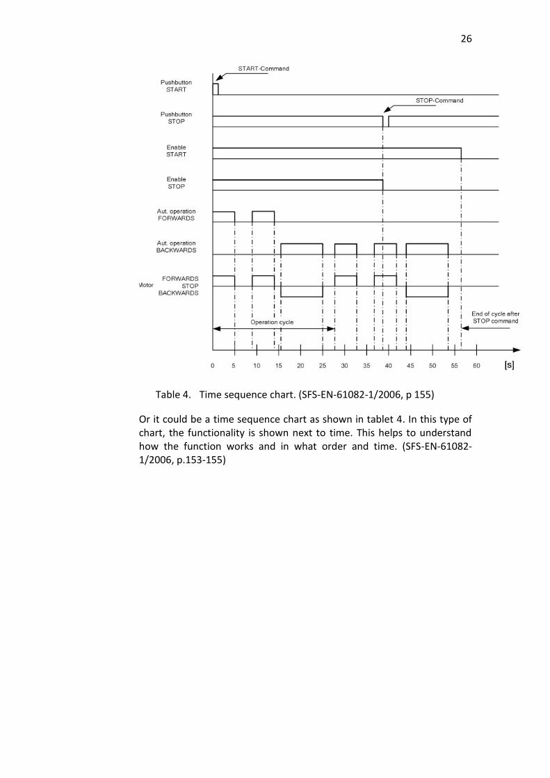
3.5 Charts and graphs
Documents can hold also different charts and graphs that may help understand information easier. These could be used to explain functions behaviour. These could also be different types of time tables of projects schedules or a chart of how much of testing has been done. (SFS-EN-61082-1/2006, p.153-155)
26
Table 4. Time sequence chart. (SFS-EN-61082-1/2006, p 155)
Or it could be a time sequence chart as shown in tablet 4. In this type of chart, the functionality is shown next to time. This helps to understand how the function works and in what order and time. (SFS-EN-61082-1/2006, p.153-155)
27
4 COMMERCIAL PROGRAMS
These three programs were selected for this thesis because Valmet has some knowledge with these programs already. CADS has been used in Valmet Paper and some of Valmet´s parts are already made for this program. EPLAN was selected because one of Valmet Automations branch office has bought this program last year. E3 was selected because it is the competitor for EPLAN. All these programs have databases that Network Designer does not have.
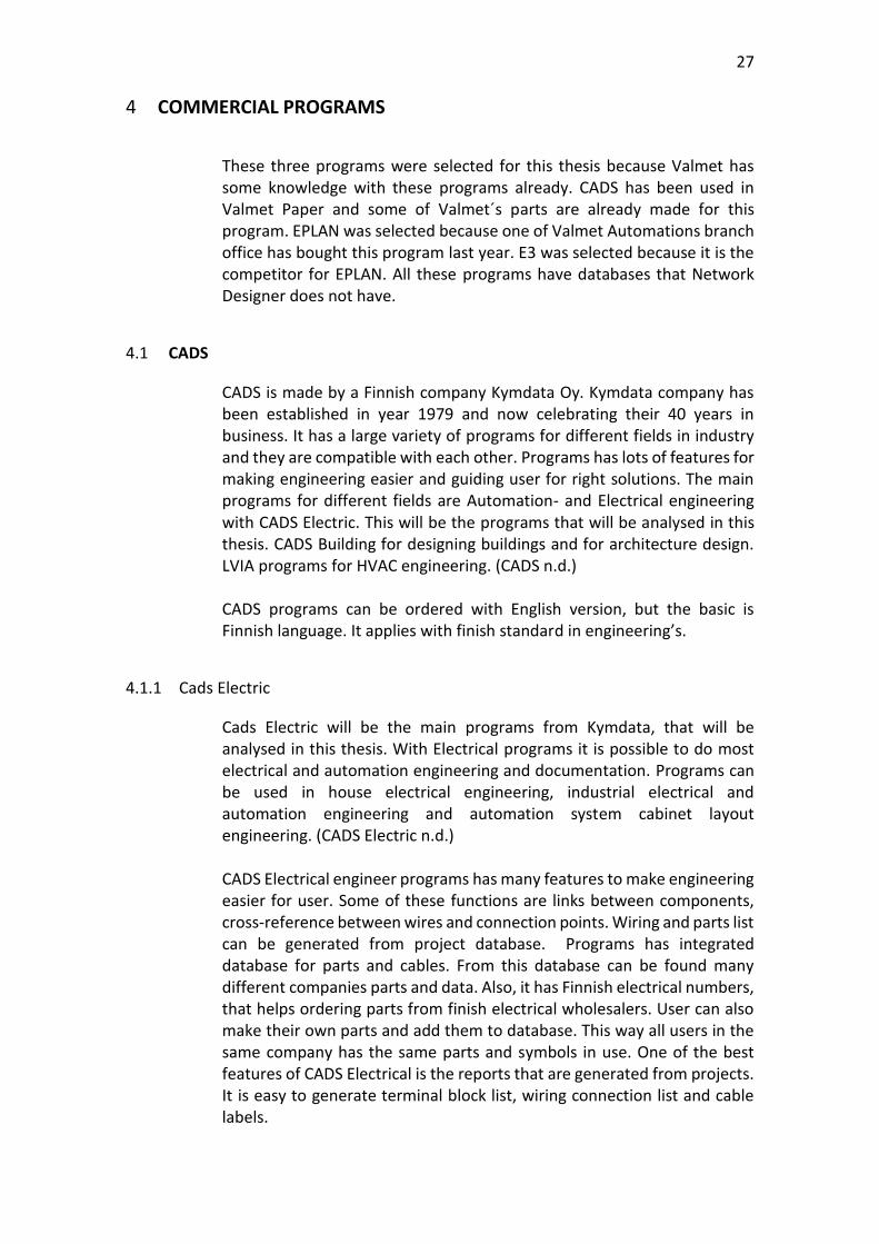
4.1 CADS
CADS is made by a Finnish company Kymdata Oy. Kymdata company has been established in year 1979 and now celebrating their 40 years in business. It has a large variety of programs for different fields in industry and they are compatible with each other. Programs has lots of features for making engineering easier and guiding user for right solutions. The main programs for different fields are Automation- and Electrical engineering with CADS Electric. This will be the programs that will be analysed in this thesis. CADS Building for designing buildings and for architecture design. LVIA programs for HVAC engineering. (CADS n.d.) CADS programs can be ordered with English version, but the basic is Finnish language. It applies with finish standard in engineering’s.
4.1.1 Cads Electric
Cads Electric will be the main programs from Kymdata, that will be analysed in this thesis. With Electrical programs it is possible to do most electrical and automation engineering and documentation. Programs can be used in house electrical engineering, industrial electrical and automation engineering and automation system cabinet layout engineering. (CADS Electric n.d.) CADS Electrical engineer programs has many features to make engineering easier for user. Some of these functions are links between components, cross-reference between wires and connection points. Wiring and parts list can be generated from project database. Programs has integrated database for parts and cables. From this database can be found many different companies parts and data. Also, it has Finnish electrical numbers, that helps ordering parts from finish electrical wholesalers. User can also make their own parts and add them to database. This way all users in the same company has the same parts and symbols in use. One of the best features of CADS Electrical is the reports that are generated from projects. It is easy to generate terminal block list, wiring connection list and cable labels.

28 4.1.2 CADS Electrical Pro
CADS Electrical Pro user can start project from anywhere user want’s. This gives opportunities for adjusting workflows and get better efficiency out of engineering. This also gives the opportunity for starting engineering from are that has needed primary information at hand. No need for waiting, this gives engineering flexibility. Old projects can be reused to maximize efficiency. (Start the design anywhere you want n.d)
4.1.3 CADS database
CADS database it is possible to edit data from anywhere. It is possible to edit terminal numbers in schematic window and this will be updated also to cabinet layout. This prevents the same information’s editing to multiple place that lowers engineering efficiency and leaves place for human errors to accrue. (Edit data wherever you want n.d)
Figure 16. CADS database links to different documents types. (CADS Electric 17 n.d)
CADS database is the base for projects. It is the centre that collects all information in to one place. As in the figure 20 is shown, all different functions are connected to database. CADS uses Excel for mass editing. Excel and database adds efficiency to engineering. In CADS project data can be changed at database or by exporting information to excel. Whit this feature the project information can be changed fast and effectively. All modifications done in database will be automatically spread to schematics and panel layout. (Machine and equipment controls n.d) CADS uses product models. With product model’s user can select different symbols for parts, connector, technical and product information. For device symbols user can select 2D or 3D. User can also make ready-made part packages as product models. (Machine and equipment controls n.d)

29
I/Os can be imported to CADS database via Excel. I/Os information must be in specific format in Excel for CADS to understand it. It is also possible to export I/O data from CADS database. This information can be imported to PLC programs. (PLC and automation systems n.d) With CADS I/Os connections points can be added with the information given to database. This makes the automation system cabinets internal alarm connections easy to make. An example of this is shown in figure 21.
Figure 17. CADS I/O modules.
User can freely add new data fields if other aspect for project database is needed. This new data can be uploaded to documents with given attribute automatic. An example of this would be, if a user adds process information for equipment, this information can be used in reports or in further in the process as a part of principal designing. Excel imports user can bring information from different supplier or ERP-systems. This can be used to bring I/O information to database or part information from company’s ERP-system. (Data management n.d) With CADS the engineering is smart, effective, fast and with less errors. With database and automatic functions this can be achieved. (Smart, effective drawing functions n.d)

30 4.1.4 CADS Layout
CADS uses real measurements for parts symbols when designing panel layout. This ensures engineer that parts will fit in real life to panel. This applies for both 2D and 3D engineering.
Figure 18. 2D field automation cabinet layout.
With the figure 22 example layout, the automation system cabinets manufacturer could assemble the cabinet and because real measurements are used, the engineer can be sure that all parts will fit as they are designed. CADS electrical has the solution to meet all needs with accurate cabinet layout drawing in 2D and 3D. Efficient tools to create schematics, database to move information between documents and database. Modifications made to cabinet layout page will automatically make corrections to rest of the project. (Manufacturing switchboards and distribution boards n.d)
31 4.1.5 CADS DM
CADS has a DM (document management) system that can be used to help manage the project documents. This helps by keeping all project in-formation up to date automatically. This ensures that all personal working on the same project has all the same information. This can be achieved because of the interface between DM and Electric. All information is immediately updated to either to DM, if drawings in electrical is changed, or to drawing if information in DM is changed. From DM user can print reports such as cable and connections lists and with the knowledge that there are the with the newest information. From DM also, the revision can be easily managed. All old document revision is stored so that user can always go back to older revision. (Document management n.d)
4.1.6 CADS links and supported files
CADS supports wide range of different file types. All the major like DRW, DWG, DXF and PDF. It also supports import and export to Excel. CADS also haves a module called Rasta, whit this module it is possible to import and edit scanned documents. The types can be FIFF, BMB and JPG. With CADS it is also possible to connect to company’s PDM/PLM database. CADS has link to DIALux. With DIALux it is possible to import and export lighting designs. (Simply compatible n.d)
4.2 EPLAN Introduction
EPLAN is part of company name Friedhelm Loh Group. Company is family based and main office is in Germany. Company has 18 production plants worldwide and 80 internal affiliated companies. Company employs over 11 500 people and has a revenue of 2,5 billion euros in 2017. (Efficient Engineering is when a PLAN becomes EPLAN n.d)

32
Figure 19. Performance Description EPLAN Electric P8 (EPLAN, 2016, p.13)
EPLAN programs has many different engineering solutions like:
Mechanical engineering
Electrical engineering These solutions work to getter and has the same Application Programming Interface (API). This allows engineers from different areas to work on same project with one project database. All supported API are shown in the figure 23. (Efficient Engineering is when a PLAN becomes EPLAN n.d)
4.2.1 Electrical P8
EPLAN’s Electrical P8 is E-CAE (Electrical Computer-Aided Engineering) -programs, that has database. With Electric P8, engineers can do Electrical schematics and layouts of cabinets or field boxes. It has many different options for project planning, documentation and management of projects. With EPLAN’s automatic reports it is possible to make reports of parts and wiring fast and effectively. With Electrical P8 is possible to reduce engineering time with schematic macros. One schematic macro can have many ways of showing the schematic. EPLAN has multiple supports for different global standards like IEC, NFPA, Russian GOST and Chinese GB. EPLAN has many engineering helping features as auto and smart connecting, macros, automatic creation of cross-references. With Data Portal engineers can download needed parts to project. (EPLAN, 2017, p.10)
33 4.2.2 Pro Panel
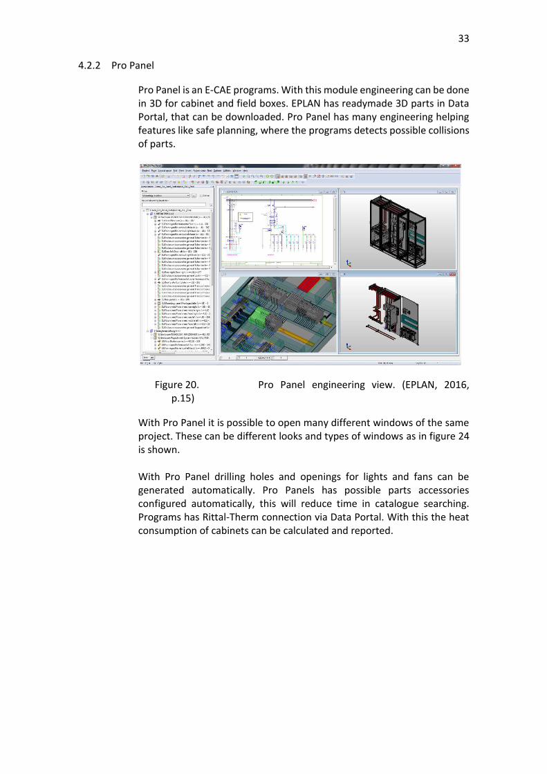
Pro Panel is an E-CAE programs. With this module engineering can be done in 3D for cabinet and field boxes. EPLAN has readymade 3D parts in Data Portal, that can be downloaded. Pro Panel has many engineering helping features like safe planning, where the programs detects possible collisions of parts.
Figure 20. Pro Panel engineering view. (EPLAN, 2016, p.15)
With Pro Panel it is possible to open many different windows of the same project. These can be different looks and types of windows as in figure 24 is shown. With Pro Panel drilling holes and openings for lights and fans can be generated automatically. Pro Panels has possible parts accessories configured automatically, this will reduce time in catalogue searching. Programs has Rittal-Therm connection via Data Portal. With this the heat consumption of cabinets can be calculated and reported.
34
Figure 21. Pro Panels auto wiring feature. (EPLAN 2018)
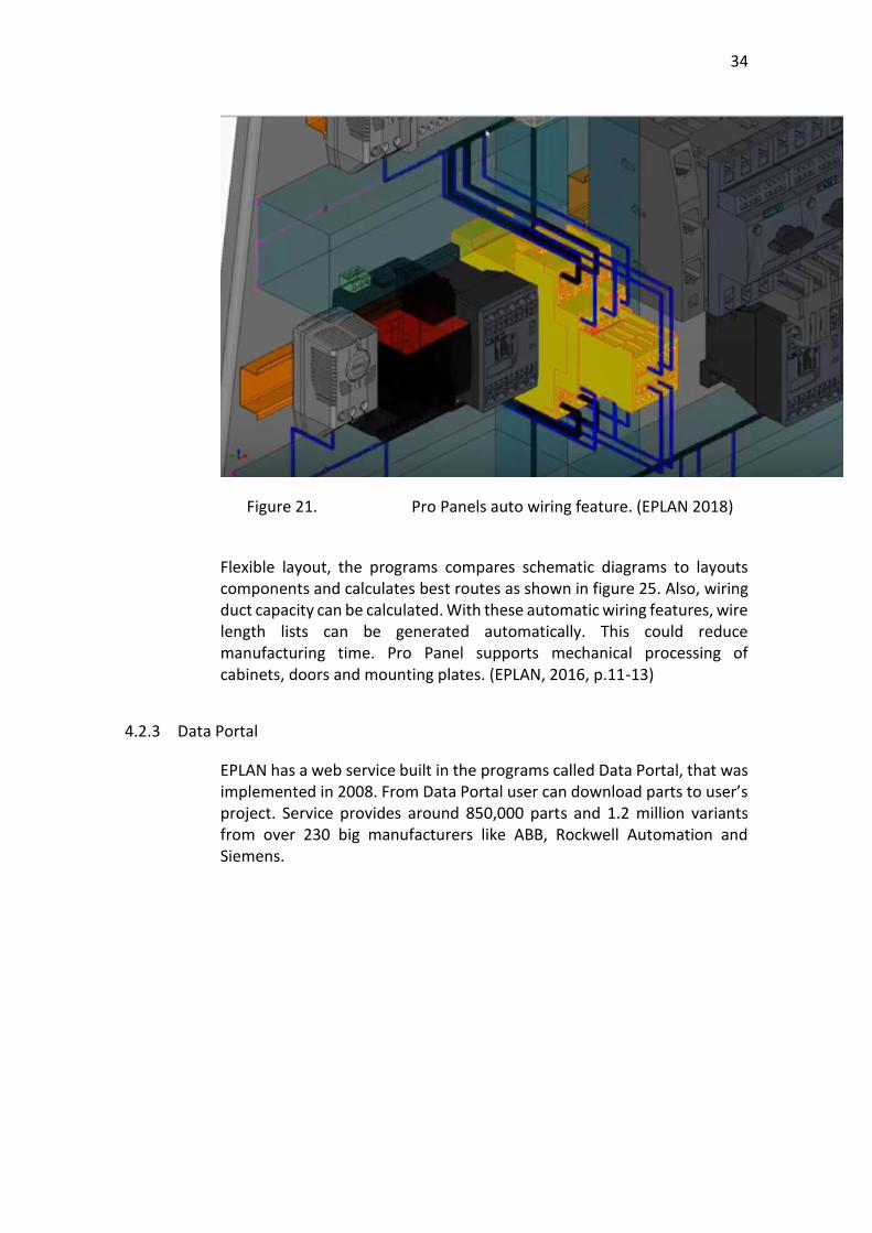
Flexible layout, the programs compares schematic diagrams to layouts components and calculates best routes as shown in figure 25. Also, wiring duct capacity can be calculated. With these automatic wiring features, wire length lists can be generated automatically. This could reduce manufacturing time. Pro Panel supports mechanical processing of cabinets, doors and mounting plates. (EPLAN, 2016, p.11-13)
4.2.3 Data Portal
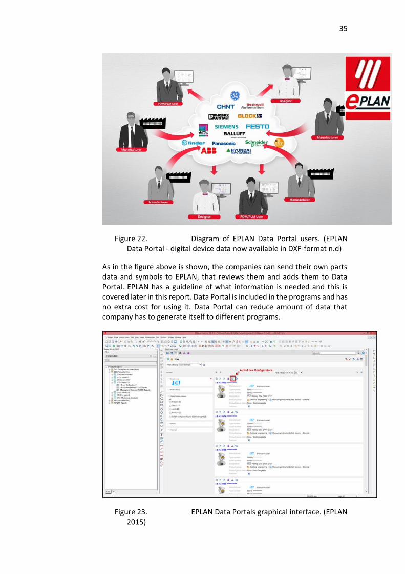
EPLAN has a web service built in the programs called Data Portal, that was implemented in 2008. From Data Portal user can download parts to user’s project. Service provides around 850,000 parts and 1.2 million variants from over 230 big manufacturers like ABB, Rockwell Automation and Siemens.
35
Figure 22. Diagram of EPLAN Data Portal users. (EPLAN Data Portal - digital device data now available in DXF-format n.d)
As in the figure above is shown, the companies can send their own parts data and symbols to EPLAN, that reviews them and adds them to Data Portal. EPLAN has a guideline of what information is needed and this is covered later in this report. Data Portal is included in the programs and has no extra cost for using it. Data Portal can reduce amount of data that company has to generate itself to different programs.
Figure 23. EPLAN Data Portals graphical interface. (EPLAN 2015)
36
From Data Portals graphical interface as shown in figure 27, user can search for the needed component with manufacturing numbering or browse through specific categories. When component is found, the user can check the components information and check that it has all needed macros and information.
4.2.4 Basic Projects
In basic projects engineer can choose from templates and create new projects. By filling out the project’s basic information, the master data for project can be forwarded to all documents at once. This data consists of project settings, project data and master data. In settings engineer can choose basic schematics and what standard is needed. Master data handles the projects symbols and forms, from here can be selected project header and needed reports. The basic project structure is based on IEC 81346. The label is made by levels. Example structure = E90+JB03+A1 = Preceding sign for the identifier block "Higher-level function E90 Higher level function or in this case location of cabinet + Prefix of the following structure identifier for the identifier
block "Mounting location" JB03 Structure identifier or in this case cabinets name - Preceding sign for the identifier block "Device" A1 Structure identifier or device identifier (Basic Projects n.d)
4.2.5 Symbols
EPLAN’s schematic has symbols that are similar to CAD symbols. EPLAN provides symbol libraries that contain symbols of different standards. Using these symbols engineering can be done always the same way. With symbol editor, engineers can make their own symbols. Symbols can have many variants, this means that the symbol has a different view of representing the same thing. (EPLAN, 2017, p.27)
4.2.6 Auto connecting
EPLAN has auto connection where the connection between symbols are made automatically. This can be either vertically or horizontally, when symbols connection points are lined together. Corner blocks can be used if connection points are not linked together. (EPLAN, 2017, p.28)

37 4.2.7 Automatic Cross-reference
With cross-reference feature it is easy to distribute devises on multiple pages. EPLAN has automatic generation of cross-reference point for the following purposes:
Symbol cross-reference
Device tag list cross-reference
Interruption point cross-reference
Cross-reference to device overview page
Mounting panel cross-reference. Engineers can choose from different options to configure cross-reference. Automatic cross-reference saves engineers time and ensures the correct referring point is in schematic. (EPLAN, 2017, p.28)
4.2.8 Macros
Macros can be made from schematics diagrams that are commonly used by user or company. This can be a window macro, where the hole page is one macro or a partial macro. In partial macros a part of schematic is made as a macro and saved to later use. A macro can contain sixteen variants and eleven representations of schematic or symbol in one file. Macro navigator shows the macros and makes it easy for engineer to select the needed one. When adding macro to schematic, it can show user-defined text or numbers. (EPLAN, 2017, p.30)
4.2.9 Reports
EPLAN has many different reports that can be added to project template. These can be automatically generated. Normal assembly reports like bill of materials, terminal and cable lists can be generated. For projects general reports would be table of contents, title or cover pages, connection list and plot frame documentations. Graphical reports can be generated automatically. The reports would show graphically a specific terminal blocks diagram and pin-connection diagram. (EPLAN, 2017, p.45)
4.2.10 Single- & Multi-Line
Single-line is a schematic type were schematics are shown with one line. Usually these are used in overviews of main circuits. EPLAN has IEC 60617 standard symbols for single line. (EPLAN, 2017, p.55) Multi-line schematics are normally used in EPLAN engineering. With multi-line all wires are shown in schematics, compared to single line where three-phase connections were shown with one line. With multi-line all needed information can be placed into schematics. With multi-line

38
schematics all connections points and wires are shown to get the accurate view of schematic. (EPLAN, 2017, p.55)
4.2.11 Revision Management
With the revision management feature, it is possible to document revisions automatically. The programs will automatically make a draft of the new revision, when user has modified the document. The modifications will be highlighted. This is marked with a water mark on documentation and will remain until the page is closed. Revision management fulfils requirements on traceability. (EPLAN, 2017, p.56)
4.2.12 Schematic
In schematic documents engineers can represent components and connections with graphical symbols. Components has functions that is shown in the graphical symbol. EPLAN has a database, so the symbol does not have any data, it is just a represent of the part. All data is stored in functions, that stores the data to database. For symbols, it is possible to add a specific part. This way the actual part data will come to project. This data would be an actual part symbol to layout, ordering information to part list, actual part size and possible weight and in some cases price, if this is given. This modification is possible to do in the parts management window, in which it is possible to add additional part information’s to parts like identifier. (EPLAN, 2017, p.56)
4.2.13 Multi-user in EPLAN
With EPLAN multiple users can work with the same project at the same time. Engineers can check from “EPLAN Multi User Management” module who is working on the project and what part they are working on. This allows multiple users to work on different sectors of the project, which is usually used in larger projects. (EPLAN, 2017, p.22)
4.2.14 User Rights Management
With EPLAN’s user right management licence, there is the possibility of adding restrictions to users. Management can block tree structures, block dialog, menu items and toolbars. (EPLAN, 2017, p.22)
4.3 E3
E3 is made by Zuken company. Zuken is one of the leading programs and consulting firm globally when electrical or electrical design is in factor. Zuken was founded in 1976 and has a long history in programs industry. (CAD vs CEW vs CAM: What is the difference? n.d. p2.)
39
It is a Windows-based programs, that can easy to learn wiring and control systems. E3 has different types of solutions for different engineering needs. E3-Schematic is for circuit and fluid diagrams. E3-Cables are used for advanced electrical and fluid design. E3-Panel can be used to design cabinets panel layouts and E3-formboard is for wire ring harness manufacturing design and manufacturing. E3 uses an object-oriented systems architecture, that has database. With database the programs can synchronize engineering designs to all stages of project. (CAD vs CEW vs CAM: What is the difference? n.d. p2.) E3 programs supports many different data formats. These are DFX/DWG, STEP, JPG and GIF just to name few. All these formats can be imported or exported from or to programs. (CAD vs CEW vs CAM: What is the difference? n.d. p2.)
4.3.1 E3 License
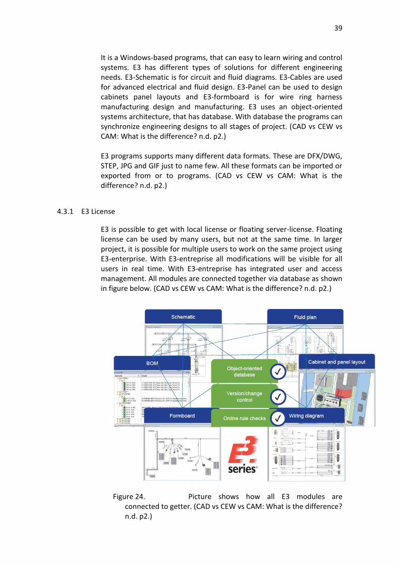
E3 is possible to get with local license or floating server-license. Floating license can be used by many users, but not at the same time. In larger project, it is possible for multiple users to work on the same project using E3-enterprise. With E3-entreprise all modifications will be visible for all users in real time. With E3-entreprise has integrated user and access management. All modules are connected together via database as shown in figure below. (CAD vs CEW vs CAM: What is the difference? n.d. p2.)
Figure 24. Picture shows how all E3 modules are connected to getter. (CAD vs CEW vs CAM: What is the difference? n.d. p2.)
40 4.3.2 E3-schematic
E3-schematic is for electrical wire design. E3-schematic is the base for all E3 modules. With E3-schematics electrical engineers can design electrical schematics, PLC’s and terminal blocks. Programs is designed to help user to improve their designs and eliminate errors. With database this can be achieved and will reduce engineering times. Programs has rule checks that works in real time. Rule check is designed to prevent errors before they accrue. This way user does not have to correct design after words. With component library parts are easily selected. Library is intelligent and help user to use right parts and design. And has good features such as, short circuit prevention, reuse stored sub-circuits or modules. With E3-schematics all data can be reported, such as bill of material and datasheets. (CAD vs CEW vs CAM: What is the difference? n.d. p3.)
4.3.3 E3-cable module
With E3-cable module that is an extension for E3-schematic, can be documented and designed cable plans. Individual wires can be combined to form harness or new cables. E3-cable also supports shielding and twisted-pair cables and can show them in schematics. E3-cable supports single-line documents, cable plans and wiring diagrams. (CAD vs CEW vs CAM: What is the difference? n.d. p4.)
4.3.4 E3-panel
E3-panel supports both 2D and 3D engineering. E3-panel has engineering helping functions such as automatic snapping point, that helps placing parts in right position. E3-panel helps engineer panels without possible component colliding’s. Because E3-panels is easy to use, user does not need to have experience with MCAD tools before starting with E3-panel. E3-panel works with E3-schematic and it is possible to modify schematic from E3-panel module. E3-panel has function that can automatically add wires to panel layout and find the best possible route. At the same time of wire routing the programs can calculate the duct fill capacity. Reports of all wires lengths can be generated after and this report can be given to wire machine, that prepares wires courting to report by cutting, crimping and marking the wires. This helps manufacturer and makes wire ring faster. (CAD vs CEW vs CAM: What is the difference? n.d. p6.)
4.3.5 E3 Revision management
E3 has an extension module for revision management. With this module user can be sure all modifications are marked and could be tracked. This module compares old and new document and if any changes are in graphical or text format the programs will inform user about changes. (CAD vs CEW vs CAM: What is the difference? n.d. p6.)

41 4.3.6 E3 link to machines
With E3 it is possible to give drilling, punching information to Perforex machine. This will make accurate holes for lights, fan and buttons to door. Also wire preparation machine Komax is supported. (CAD vs CEW vs CAM: What is the difference? n.d. p8.)
4.3.7 E3 Reports
E3 offers many possibilities for reporting projects. These are bill of material, cover sheet, index sheet, connection point- and cable-list, terminal block list and name plate reports. These are basic reports that are needed in projects, but many other reports can be generated also. (CAD vs CEW vs CAM: What is the difference? n.d. p8.)
4.4 Conclusion of programs after introduction
Because of limited time and resources, one programs had to be drop out from the continuation of analyse. When comparing these programs at this introduction level, the E3 programs did not show any better solution than CADS or EPLAN. Because CADS and EPLAN is already in use in Valmet Automation at some level and E3 did not have any special extra functions compared to other two programs, there was no point in taking a new program when it would not bring any new functions or efficiency compered to CADS or EPLAN. Because of this reason E3 is dropped and CADS and EPLAN programs will be analysed further in this thesis.

42
5 FURTHER ANALYSIS BETWEEN EPLAN AND CADS PROGRAMS
CADS and EPLAN will be further analysed by their features and the us-ability in Valmet Automation. As in chapter 1.4. was stated that the programs must have database, but because both programs have database, the quality and usability of the database will be one criteria in comparison.
The standards that the programs support and how they are implemented to the programs. Can the programs be customised for Valmet Automation’s needs?
The quality of shapes and the parts information in database.
Globality in support langue’s and support team locations. In how many countries it is used and the amounts licenses.
One important aspect in this analyse is to take in count the possibility of third party engineering companies using Valmet´s parts in their own projects.
Programs should increase the efficiency of hardware engineering. For both programs the researches will start with programs basic training. After these trainings are done, the final verdict on programs will be given.
5.1 EPLAN
In this chapter I will analyse EPLAN programs and report on EPLAN’s basic training.
5.1.1 EPLAN Basic Training
I participated in EPLAN’s basic training that lasted for 32 hours. In this training we did a small project and at the same time went through the programs basic ways of use and functions. We learned how project and project database is created. We went through how to add symbols and parts to project and how to edit them. The best features of this program are the project database, and this was one of the main feature of this training. Things we went through in the training:
Making new project and library
Basic drawing ways
How to generate reports
How to revisions are made
How new products are imported to project database
How to make own symbol, product and macro
2D cabinet designing

43
Also, trainer showed how Pro Panel works We did not do any topology engineering. This would need a different program and license, but when I talked with the trainer, I got feeling that it would not work for large topology drawings. The program has lots of good features, but also some weaknesses. I have listed them here. The good feature of the EPLAN programs is its database. The database helps users in larger project, but also in smaller ones if there is a lot of copying. If cabinets would be identical, with same part and configure, but the parts identifiers would change. When almost all the components are the same in copy cabinet, the copying is fast, because the identifier must be changed only in the database. With a program that does not have database, the identifier must be changed to all pages where component is shown. In this case the human mistake is easily made. This is also a great feature when designing automation system cabinet layout. Layout can be engineered first and all the part that are used in layout is added to project database. After layout engineering is done and schematic diagrams are started, the components can be added from database. This will bring the right symbol and part data to wiring diagrams. Importin products from EPLAN Data Portal is easy way the get a new component that is needed in the project. This products shape has been made by the manufacturer and has all needed information inside the shape. The imported shape contains 2D shape for cabinet layout and IEC – standard symbol for electrical wiring diagrams. Also, it can contain macros, where the symbol is differently shown. This means that the macro can contain terminal block that has 20 terminals, but the next macro shape only shown the first 5 terminals. The part can contain also UL and CE certification number and this information can be added to part list report (to get this information to shown in part list report, the report template must be modified). Some products have picture of the component, datasheet or hyperlink with the product datasheet. In some case this information is great and speeds up the engineering work (less time in searching product information’s from google). One good this in Electrical P8 is that the cable marking is done easily, and the cable type can be selected from database. The selected cable type is shown next of the cable. Also, when the cable type is selected, all cables in the project can easily be printed to report. Cables are drawn with corned blocks, no traditional line pulling is needed. The cable line is automatically connecting between two connections point. If these two connection points are not inline, the corner blocks are used.

44
Jumping in wiring diagrams referents points. This means that, if on top of the referent point is bushed, the user is jumped to the next reference point. This helps the user to find where the connection is continuing. Electric P8 has multiple connections to different manufacturers platforms. This can be useful when cable marking is done by cabinet manufacturer. Of course, the manufacturer must have EPLAN to use this feature. Also, RITTALs hole machine can use this connection platform straight. The 2D cabinet layout looks old and is slow to use. The EPLAN is mainly updating Pro Panel, that is 3D layout engineering program. This Pro Panel needs its own license and is not part of the Electrical P8 license. Because this is not part of the Electrical P8 program, we did not use this in the training. But the trainer showed how it works in a brief minute or two. This looked better and had features that would be needed in cabinet designing. But still there were room for improvement even with this Pro Panel. One main problem with the Electrical P8 is that if a product is changed in the project, and this change is done to project database, the part information will be changed to shapes, but not the actual shape. Example if project layout has spring terminal ST4 and project demands is changed from spring to screw. This can be modified to project data base and the part change will be divided to projects all documents. In layout page this will change the part information, but not the actual symbol of this part. Also, there will be no warning or marking on the changed shapes. So, the user must remember to manually change the actual shapes to all pages. This is a potential place for human error. This should also replace the new symbol to drawings and if it’s a different size than the old one in cabinet layout, it should give warning message. Also, the revision in default is too sensitive. If user does even a small modification like moving a identifier, this would put the page to draft mode and will need to be made as a new revision. The automatic sensitive should be set so that the new revision is only made if new part or symbol is added to drawing or connection point has changed. There is no need for new revision if things are moved for better visual look. Other point in revision is that the part list can´t make a comparison between last revision and the new ones. This means that the manufacturer must manually compare the part list or make an excel comparison macro to find out what parts has been changed. If user rights needed to be restricted, this will need an extra license. Also, it seems that there will be a lot of different license, this can be very confusing for the end user. Good feature if done right. If template is done right, it would make hardware engineering faster and with better quality. But if done poorly, there would not be any benefits in these templates.

45 5.2 CADS
In this chapter I will go thru the basic training courses that was taken for this thesis and what things were learned. CADS training courses was held with webex over the internet. It was in three separate modules, I have open every module in the chapters below. Also, CADS was teach shed at school, so some of the information in these training courses was familiar.
5.2.1 CADS Electric Lite Basics Training
This training was more for house electrical engineering, but the basic functions are the same as in industrial engineering. First, we added a DWG documents to CADS. This document was a document of a houses ground plan, this will be a reference image and on top of this document the house electrical engineering will be done. This way the houses ground plan does not have to be done with CADS and this way the ground plan will be the same as the architect has it done. Basic functions such as Snap and Undo. Basic keyboard buttons. How to use dimension tool, to check that the drawing is done in correct scale. We started to place socket and lights to house document, this was easy, and no problems accrued when doing this. When socket is added the Snap function should be on and Snap extra function Near should be selected. With Near function the socket will snap to house wall when socket is placed near the wall. Light can be added to rooms middle with CADS function that calculates the centre point of the room and add the light there. This makes it easy to add light to middle of the room. Also, these things were covered in training:
How shapes size can be modified.
How header can be modified from sheet options.
How to fill initial order sheet.
How filling function is used and how the automatic filling is used. Schematics training started with drawing a 3 – phase line to top of the schematics. And by adding fuses, soft starter and motor to schematics as shown in figure 29.

46
Figure 25. Schematic with CADS
Last thing that was covered in training was how to print is done and what attributes must give to printer to get the documents in right scale and with correct colours. Basic training gave the basic information about starting the project and the basic functions on how to use programs. This training would be good for new user, but for me this did not give new information. All this information was given in schools CADS lessons.
5.2.2 CADS Industrial engineering training Basic
First in the training were the basic functionality of the CADS Electrical programs. These functionalities were:
Snap functions that is wise to keep active. With Snap the cables or wire will automatically connect when connecter when they are bringing close to connector.
Basic information about the programs menus and what functions they contain.
How autosave is enabled.
Printer setup and the settings for printer.
DWG format settings.

47
After basics information and setup was done, next at agenda was creating a project and giving project information. This was easy and all given information is stored to project database. From there this information can be spread to every document. At this time, we went also through project tree and how it is used. This applies to standard project tree structure. Next, we started with schematic drawing and the basic of it. We made one example project schematics and at the same time went through basic thing about drawing schematic with CADS. These were:
How to place symbols in document
Three phase power line drawing
How to modify schematics
How to add cross-reference points
How wiring is drawn This training gave more information on how to start a project, but not much of new information. All of these things were gone through in schools CADS lessons.
5.2.3 CADS Industrial engineering training Pro
Some of the information in this training was the same as in basic course like creating project, project three and the use of it. Basic information about the database and how it is most efficient to use. How to mass edit in database. How to export and import from and to excel. Excel has better possibilities for mass editing and this would be the better solution when large amount of information must be edited. How links from databases parts can be used to find parts datasheets. One important thing when editing information in database is that all changes are affected immediately, so if wrong information is changed there is no undo possibility. Next, we went through how cables are searched from CADS database and added to project. How part text is added and how this differs from normal text. Part text can be automatically translated to other langue if needed, but the normal text must be changed by hand. Also, how part information can be changed in database and how this will automatically be updated to all document in this project. How part can be created if it is not found from CADS database. How part shape can be imported from internet and modified to meet company’s standards. And how PDM integration works between CADS and ATON as shown in figure 30. With this link company’s ERP-number can be imported from ATON to CADS.

48
Figure 26. CADS and ATON communicates both ways. (CADSiin tulossa PDM-rajapinta n.d)
We went through how plates are made and how list of them are generated. These plates could be name plates for cabinets, IO plates, Cable plates and part plates. In the last part of training we learned about schematic and layout drawing. Schematic training did not bring any new information, but the layout drawings was new. In this we learned how to create and add page setup the right way. How from project tree can select a part and add it from there to layout. The cabinet drawing is easy, so this was not covered in this training. One point that the trainer stated was that the 3D drawings makes a lot of extra work and should be consider carefully if this would give any extra advantage comparing to 2D. In final training there were some new information about CADS and use of it. The database works well and would give engineering more efficiency than Network Designer.

49
6 FINAL CONCLUSIONS OF PROGRAMS
When comparing these two programs it is hard to say which would be the better solution for Valmet Automation. Both have similar functions and the differences are narrow in layout and schematics.
6.1 Market share
CADS is well known in Finland, but less at a global scale.
Table 5. CAD programs market shares in Finland (CADS Product Suite n.d).
In figure above is shown the market share for CAD programs in Finland. This Gallup has been done by TNS -Gallup Oy in 2016. It shows the programs market share in present in three different years. Dark blue represents year 2016, light blue 2014 and grey is market share for 2011. CADS has increase their market share by ten presents in five years. EPLANs market share is only four presents in 2016. EPLAN is more known in global scale and it is used in over 50 countries and have 19 different languages available. EPLAN programs is used by 50 000 customers in a daily base. (EPLAN Programs & Service n.d) With the better global name and with a bigger programs user base the EPLAN would be a better solution. EPLAN has a strong market share in

50
central Europe and Valmet Automation has many projects in this area. In these projects the customer could demand EPLAN as the project documentation format. And many consult companies that Valmet Automation uses in central Europe projects has EPLAN already and uses it in project for other companies. With EPLAN the programs would be familiar, and the project work would be efficient from the beginning.
6.2 Layout engineering
CADS has the basic functions to make automation system cabinets layout engineering. This is already used in Valmet Paper and there are some Valmet components already made. This would make the transaction faster and easier. CADS has the possibility to convert the layout to 3D, but this would need a lot of extra work to make all parts in 3D. It can be made with 3D boxes, but this would not give any advantages to 2D engineering. EPLAN has two options for layout engineering. Electrical P8 licence is used for 2D layout engineering and it is missing some of the new features that is in Pro Panel licence. Pro Panel is used to engineer 3D layouts and has new features like collision check where the programs can check if any components are colliding. This could happen when components are also placed on automation system cabinets side wall. This component could collide with a component at the back wall. Other feature that is only in Pro Panel is automatic wire routing and cable duct filling degree calculator. With this the wire length can be calculated and added to reports, this could reduce manufacturing time. With Electrical P8 vs CADS the layout features are quite equal. CADS does not guide the user as much as EPLAN. EPLAN show connection point for components when adding them to layout. The difference between Pro Panel and CADS is bigger and if 3D engineering is needed, then the only real option would be EPLAN. The EPLAN shows better options for layout engineering. With the better data portal to download parts shapes, the best option would be EPLAN. With better data portal the time to make shapes would reduce and make the engineering faster and this way achieving better efficiency compared to CADS. Valmet Automation must think about the need for 3D layout engineering. This might be the future of hardware engineering, but is it needed at the moment? Also, because the Electrical P8 and Pro Panel has their own licenses. If the engineering is done with Pro Panel at 3D, the layout can be continued with Electrical P8 as 2D. But after engineering in 2D, it can’t be engineered with Pro Panel as 3D any more. Or if project is started with Electrical P8, it can be modified or continued with Pro Panel as 3D.

51 6.3 Schematics
CADS and EPLANs schematics differs a little. The EPLAN uses auto wiring, where CADS the lines must be pulled by user. This makes the EPLAN schematics faster to engineer than CADS. Also, EPLAN has the possibility for macros, that can be made for company’s basic schematics. This would make the different macros fast to change and more efficient than CADS. The macros must be made by company well and with thought. The symbols for both programs are equivale and uses standard ones, but special symbols that represent components can be downloaded from Data Portal. With the faster wiring, macro option and symbol download from Data Portal, the EPLAN would give company better options for making the engineering more efficient.
6.4 Other issues
With CADS, Valmet would be in the same situation as with Network Designer at the moment. Third party engineering companies would need to buy CADS programs for them to do engineering in Valmet Automations projects. This would not be a problem with Finish third party companies, because they most likely would already have CADS at use. This problem would be more of a problem with offices located outside of Finland and that the companies would need to learn the uses of CADS. Also, with CADS Valmet’s hardware components could be added to engineering programs, so that it could be sold to third party engineers firms to be used in their own automation projects as it could be done with EPLAN. But with EPLAN this could be done at a global scale and this is one of the main point that must be thanked when selecting the programs. And EPLAN has better support for different global standards like IEC, NFPA, Russian GOST and Chinese GB. Both follows the IEC standard that is used in Finland, but because Valmet Automation delivers projects in a global scale, it must change standards depending on the country of end customer. EPLAN would be more flexible in this matter and would reduce time in engineering and this way giving better efficiency compared to CADS in global standards.
6.5 Criteria and how they were met by programs
In chapters 1.4 and 5 I stated some criteria for the programs. As a recap I will go through them one more time and mark which programs was better suitable to meet these criteria.
The standards that the programs support and how they are implemented to the programs. Can the programs be customised for Valmet Automation’s needs?
52
➢ As pointed out in chapter 6.4, EPLAN has a better support for different regional standards and they can be easily changed in different projects.
The quality of shapes and the parts information in the database. ➢ As pointed out in chapter 6.2, EPLAN has better library of shapes.
EPLAN has also a possibility to download more shapes from Data Portal and 3D shapes are mostly readymade. EPLANs macros gives the shapes in different styles in a representing way.
Globality in support language’s and support team locations. In how many countries it is used and the number of licenses. ➢ As pointed out in chapter 6.1, EPLAN has a better global support
and name. It supports 19 different languages, so that global offices can use their own language.
One important aspect in this analysis was take in account the possibility of third party engineering companies using Valmet’s parts in their own projects ➢ In chapter 6.4 this matter was covered. In both programs this
would be possible, but for Valmet Automation to get maximum advantage of this feature, it should be done on a global scale. EPLAN would give better chance for this in a global scale.
The programs should increase the efficiency of hardware engineering. ➢ EPLAN would give the best efficiency. EPLAN has a data portal,
that has shapes in 2D and 3D. Also macros can be downloaded from its Data Portal. Auto wiring would make schematic engineering faster than CADS traditional way of pulling the wire.
6.6 Conclusions
The conclusion of this thesis project was that EPLANs Electrical P8 and Pro Panel would give Valmet Automation the best possibilities globally. EPLAN would bring the possibility for Valmet Automation to add their own product components to Data Portal, that could increase the sales of Valmet Automations hardware components. Data Portal would also lower the time of component shape engineering, because these could be downloaded from Data Portal. With project library EPLAN could reduce human errors in projects and make the engineering quality better and more efficient.
6.7 Recommendations for future development
With the conclusions of this project, I would say that the EPLAN has good functionality and many good features such as the Data Portal, Project library and Macros so that it would be wise to further examine and

53
analyse the option of taking the programs in use at Valmet Automation on some scale. A new research project is needed, which it would take a deeper look into EPLAN. EPLAN should be tested in a real Valmet Automation delivery project and the cost and infrastructure should also be considered. Would EPLAN change the engineering flow that is used at Valmet and would engineering be done in 2D or3D with EPLAN should be considered.

54
7 CONCLUSION OF PROJECT
This thesis project was interesting and eye opening. After having been using Network Designer for eight years on a daily basis, it was interesting to learn about the other possibilities that different programs could bring to engineering, if they were to be used instead of Network Designer. But also, the possibilities of implementing some of these features to Network Designer. I learned much about different styles of CAD engineering and electrical standards that affect engineering.

55
REFERENCES
Basic Projects (n.d). Retrieved 14 February 2019 from http://www.eplan.help/help/platform/2.6/en-US/help/Content/htm/projects_k_basisprojekteerweitert.htm CAD vs CEW vs CAM: What is the difference? (n.d). Retrieved 15 March 2019 from https://www.e3seriescenter.com/modern-electrical-engineering-blog/cad-vs-cae-vs-cam-what-is-the-difference Data management (n.d). Retrieved 8 March 2019 from http://www.cads.fi/en/programs/cads-electric/industrial-electrical-and-automation-design/data-management CADS (n.d). Retrieved 7 March 2019 from http://www.cads.fi/en CADS Electric (n.d). Retrieved 7 March 2019 from http://www.cads.fi/index.php/en/programs/cads-electric CADS Electric 17 (n.d). CADS Electric 17. Retrieved 27 April 2019 from http://www.cads.fi/en/cads-electric-17 CADS Product Suite a (n.d). PDF. Retrieved 7 March 2019 CADSiin tulossa PDM-rajapinta (n.d). Retrieved 27 April 2019 from http://www.cads.fi/ajankohtaista/uutiset/cadsiin-tulossa-pdm-rajapinta Document management (n.d). Retrieved 8 March 2019 from http://www.cads.fi/en/programs/cads-electric/industrial-electrical-and-automation-design/document-management E3.Series – Electrical Wiring, Control Systems and Fluid Engineering Programs (n.d.). PDF. Edit data wherever you want (n.d). Retrieved 7 March 2019 from http://www.cads.fi/index.php/en/programs/cads-electric/edit-data-wherever-you-want Efficient Engineering is when a PLAN becomes EPLAN (n.d). Retrieved 12 February 2019 from https://www.EPLAN.de/en/company/about-us EPLAN (2015). EPLAN Data Portal News. Retrieved 13 February 2019 from https://www.eplan.fi/fi/ratkaisut/saehkoesuunnittelu/eplan-data-portal/uutiset/view/article/eplan-data-portal-more-than-100-manufacturers-28261/

56
EPLAN (2016). Performance Description - EPLAN Pro Panel Version 2.6. PDF. EPLAN (2017). Performance Description - EPLAN Electric P8 Version 2.7. PDF. EPLAN (2018). EPLAN Pro Panel Version 2.7: 3D Wiring. Retrieved 26 April 2019 from https://www.youtube.com/watch?v=DNyHjeaJXv8 EPLAN Data Portal - digital device data now available in DXF-format (n.d.) Retrieved 26 April 2019 from https://www.youtube.com/watch?v=S3KD_x0LB50 EPLAN Programs & Service (n.d). Retrieved 27 April 2019 from https://www.eplan.fi/fileadmin/data/flippingbooks/en/brochures/Image/files/assets/basic-html/page-3.html Finnparttia (n.d) MMJ 5x1,5 S asennuskaapeli. Retrieved 5 May 2019 from https://www.finnparttia.fi/MMJ-5x15-S Machine and equipment controls (n.d.E). Retrieved 7 March 2019 from http://www.cads.fi/en/programs/cads-electric/industrial-electrical-and-automation-design/machine-and-equipment-controls Manufacturing switchboards and distribution boards (n.d). Retrieved 8 March 2019 from http://www.cads.fi/en/programs/cads-electric/manufacturing-switchboards-and-distribution-boards Musselwhite, K. (n.d.). What is CAD Programs? Retrieved 7 March 2019 from https://study.com/academy/lesson/what-is-cad-programs-definition-uses.html PLC and automation systems (n.d). Retrieved 7 March 2019 from http://www.cads.fi/en/programs/cads-electric/industrial-electrical-and-automation-design/plc-and-automation-systems Pere, A & Kivimäki, J. (1998). Koneen- ja Sähköoppipiirrustuksen perusteet. Helsinki: Hakapaino Oy. SFS. (n.d.) Mitä standardisointi on?. Retrieved 9 April 2019 from https://www.sfs.fi/standardien_laadinta/mita_standardisointi_on SFS-EN-61082-1. (2006). Preparation of documents used in electrotechnology. Part 1: Rules. Helsinki: SESKO Standardization in Finland

57
Simply compatible (n.d). Retrieved 9 March 2019 from http://www.cads.fi/index.php/en/programs/cads-electric/simply-compatible Smart, effective drawing functions (n.d). Retrieved 9 March 2019 from http://www.cads.fi/index.php/en/programs/cads-electric/smart-effective-drawing-functions Start the design anywhere you want (n.d). Retrieved 7 March 2019 from http://www.cads.fi/index.php/en/programs/cads-electric/start-design-anywhere-you-want ST 13.50. (2015). SÄHKÖENERGIAN JAKELU- JA KÄYTTÖJÄRJESTELMIEN (S) SEKÄ TIETOTEKNISTEN JÄRJESTELMIEN (T) PIIRROSMERKIT. Espoo: Sähköinfo Oy Sähkönumerot.fi.(n.d.) Ohjauskaapeli - MMO 7x1,5 S R50 Eca – Draka. Retrieved 5 May 2019 from http://sahkonumerot.fi/0412012 Ruuppa, E & Perkiö, T. (1996). Sähköteknillinen dokumentointi. Helsinki: Hakapaino Oy. Valmet. (n.d.) Valmet in brief. Retrieved 12 January 2019 from https://www.valmet.com/about-us/valmet-in-brief/ Valmet. (2015) Valmet buys automation business from Metso. Retrieved 12 January 2019 from https://www.valmet.com/fi/media/uutiset/porssitiedotteet/2015/valmet-ostaa-prosessiautomaatiojarjestelmat-liiketoiminnan-metsolta-yrityskaupan-myota-valmetista-tulee-entista-vahvempi-liiketoiminnaltaan-aiempaa-tasaisempi-ja-kannattavampi/ Valmet yrityksenä. (n.d.) Retrieved 13 January 2019 from https://www.valmet.com/fi/valmet-yrityksena/ Vuohensilta, E (n.d.). Network Designer Help. Program manual.

58
Appendix 1
APPENDIX HEADING