controlador 4160
TRANSCRIPT
7/28/2019 controlador 4160
http://slidepdf.com/reader/full/controlador-4160 1/12
1
Head Office3900 – 101 StreetEdmonton, Alberta, Canada T6E 0A5Office: (780) 437-3055Fax: (780) 436-5461
Website: www.cvs-controls.com E-Mail: [email protected]
Instruction Manual
Calgary Sales Office205, 2323 – 32 Avenue NECalgary, Alberta, Canada T2E 6Z3Office: (403) 250-1416Fax: (403) 291-9487
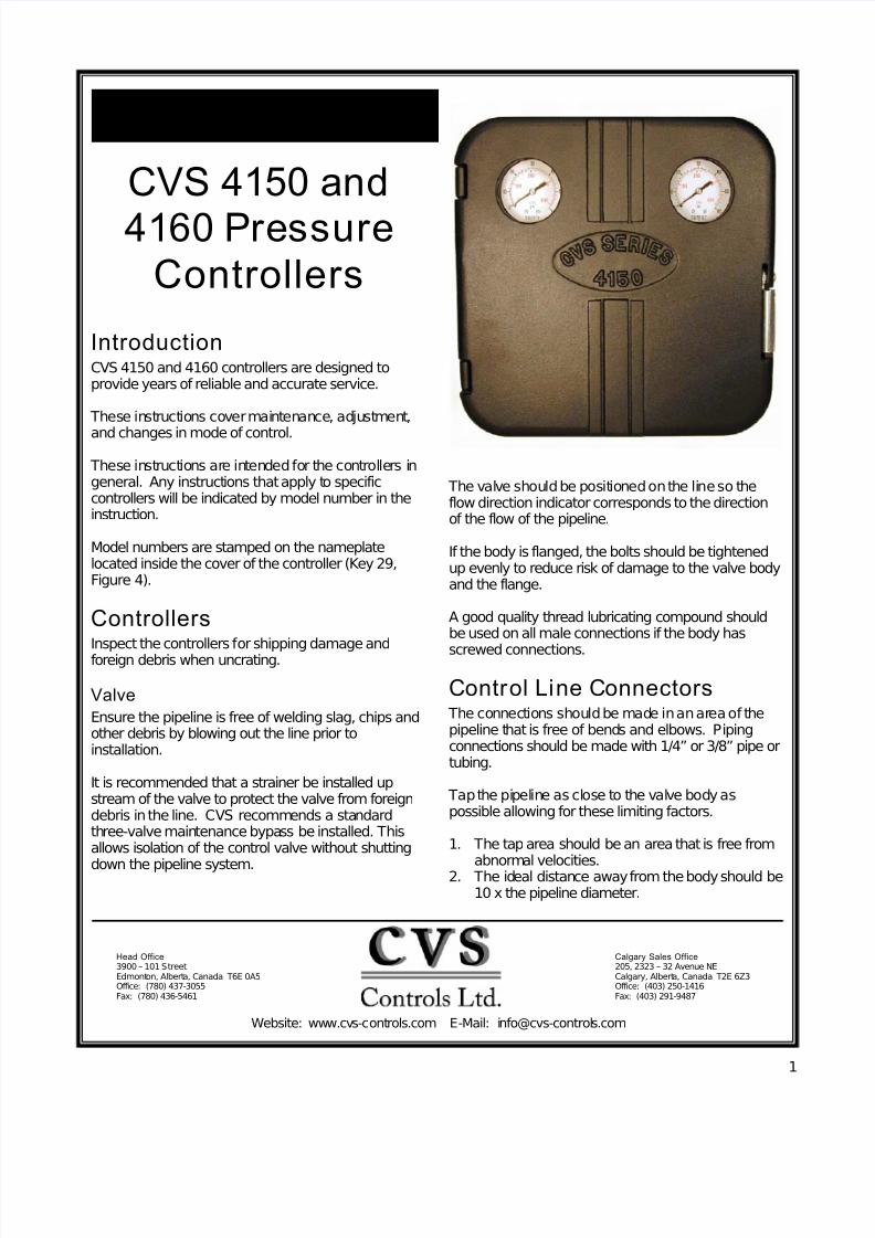
CVS 4150 and
4160 PressureControllers
IntroductionCVS 4150 and 4160 controllers are designed toprovide years of reliable and accurate service.
These instructions cover maintenance, adjustment,
and changes in mode of control.
These instructions are intended for the controllers ingeneral. Any instructions that apply to specificcontrollers will be indicated by model number in theinstruction.
Model numbers are stamped on the nameplatelocated inside the cover of the controller (Key 29,Figure 4).
ControllersInspect the controllers for shipping damage andforeign debris when uncrating.
Valve
Ensure the pipeline is free of welding slag, chips andother debris by blowing out the line prior toinstallation.
It is recommended that a strainer be installed upstream of the valve to protect the valve from foreigndebris in the line. CVS recommends a standardthree-valve maintenance bypass be installed. Thisallows isolation of the control valve without shutting
down the pipeline system.
The valve should be positioned on the line so theflow direction indicator corresponds to the directionof the flow of the pipeline.
If the body is flanged, the bolts should be tightenedup evenly to reduce risk of damage to the valve bodyand the flange.
A good quality thread lubricating compound shouldbe used on all male connections if the body has
screwed connections.
Control Line Connectors The connections should be made in an area of thepipeline that is free of bends and elbows. Pipingconnections should be made with 1/4” or 3/8” pipe ortubing.
Tap the pipeline as close to the valve body aspossible allowing for these limiting factors.
1. The tap area should be an area that is free fromabnormal velocities.
2. The ideal distance away from the body should be10 x the pipeline diameter.
7/28/2019 controlador 4160
http://slidepdf.com/reader/full/controlador-4160 2/12
2
Control Line Connectors cont’d The control pressure line is run from the tapped holein the side or the back of the case to the mainpipeline.
Install a lock shield needle valve in the control line toslow down the controlled pressure or to dampen out
any pulsations. While the control valve is operational,the needle valve must never be entirely closed.
An air vent is provided on all controllers and workswell when air is used as the operating medium.When gas is used the vent can be removed, thisallows for an additional 1/4” NPT connection for gasto be piped away.
OperationAlthough the output for these controllers are set priorto shipping, upon arrival the following items shouldbe checked.
Bellofram Type 50 Filter Regulator
Bellofram Type 50 Filter Regulator is a self-contained filter regulator designed to deliver air orgas to the pilot at a constant pressure. TheBellofram Type 50 is designed to handle inletpressures up to 250 psi The CVS Series 4150/4160delivers an outlet pressure of 3 - 15 psi when theregulator is set to 20 and it will deliver 6-30 psioutput when the regulator is set to 35 psi.
The filter component ensures that operation is clean
and dry.
The relief valve is geared to open when the pressureis reduced to 1 psi above the regulator set point.
Releasing the lock nut and adjusting the adjustingscrew located on the top of the regulator can reducepressure setting for the regulator.
Proportional ControllersMost of the proportional controls will be used inapplications that require a band set to approximately15%. The following steps are used to test thissetting.
1. The air supply should be connected to Bellofram Type 50 filter regulator.
2. Zero the pressure setting dial.3. Set the proportional band adjustment to 15%4. There should be no pressure sent to the
measuring element.5. For direct or reverse acting controllers the range
and output should be set as follows.
Range Output
3-15 psi 8-10 psi
6-30 psi 16-20 psi
Proportional-Reset Controllers1. The reset dial should be set to maximum.
2. The air supply should be connected to Bellofram Type 50 filter regulator.
3. Zero the pressure setting dial and proportionedsetting dial.
4. There should be no pressure sent to themeasuring element.
5. For direct or reverse acting controllers the rangeand output should be as follows.
Range Output
3-15 psi 8-10 psi
6-30 psi 16-20 psi
Start Up
Proportional Controllers1. The air supply should be connected to Bellofram
Type 50 filter regulator.2. Connect the control pressure line and open the
lock shield needle valve.3. Ensure all piping and connections are free from
leaks.4. Set the pressure to the desired control point.5. Proportional band should be set at 15% of the
bandwidth.6. Open the manual control valves that are
upstream and downstream, at the same timeclose the by-pass valves.
7. Set the controller near the desired control point.When it reaches that point, begin to broaden theproportional band. Broaden the band as little aspossible. The narrowest band that will not resultin cycling provides the best control. This bandadjustment will affect the zero. Re-zero the unit.
8. Test the bandwidth by changing the pressuresetting adjustment for a moment. If this causescycling, then broaden the proportional band andtest again. This procedure is to be repeated untilstability is reached.
Proportional-Reset Controllers
1. The air supply should be connected to Bellofram Type 50 filter regulator.
2. Connect the control pressure line and open thelock shield needle valve.
3. Ensure all piping and connections are free fromleaks.
4. Set pressure to the desired control point.
7/28/2019 controlador 4160
http://slidepdf.com/reader/full/controlador-4160 3/12
3
Proportional-Reset Controllers cont’d5. Proportional band should be set at 100% of
bandwidth.6. Maximize the setting on the reset dial.7. Open the manual control valves that are
upstream and downstream, at the same timeclose by-pass valves.
8. Set the controller near the desired control point.When it reaches that point, begin to narrow theproportional band until a cycling condition exists.Broaden the band slightly until a stable conditionis reached. There is no need to reset the zero incontrollers that have reset.
9. Try to obtain the fastest reset time withoutintroducing cycling control carefully by adjustingthe reset rate.
10. Test the bandwidth and the reset rate bychanging the pressure setting adjustment for amoment. If this causes cycling, then broaden theproportional band and test again. Thisprocedure is to be repeated until stability is
reached.
The goal for the controller setting is to have thenarrowest proportional band and the fastest resetrate that will not cause cycling.
Changing Controller Action
One advantage of the CVS 4150/4160 is the ease atwhich you can change from one mode of control toanother. There is a connection for both direct andreverse action in all modes of control. There is also ascrew (key 5, figure 6) provided to plug the holeopposite of the nozzle. It will be necessary to followINITIAL SETTINGS after any change in mode of control.
Adjustments
Proportional Band Width Adjustments
The proportional band width adjustment determinesthe change in control pressure required to cause thecontrol valve to travel full open or full closed.
Example: with the proportional band set @ 1(10%), using a Bourdon tube of 0-1000 psi that is
set @ 500 psi on the pressure dial. The fulltravel of the valve would occur between 450 psi(3 psi output) and 550 psi (15 psi output) to try tomaintain the set point.
Using this theory, an input pressure of 500 wouldgive you an output pressure of 9 psi. The greater theproportional band setting is the slower the reaction.
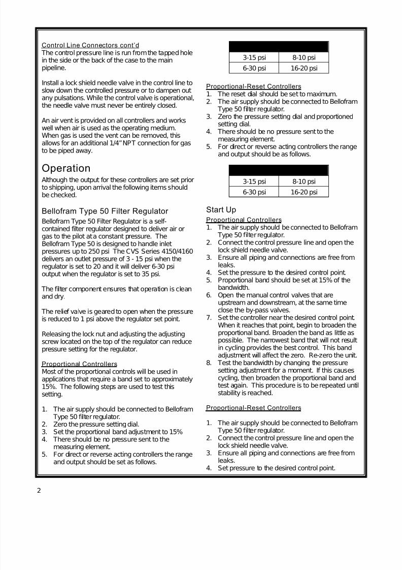
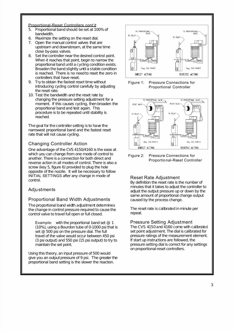
Figure 2: Pressure Connections for
Proportional-Reset Controller
Reset Rate AdjustmentBy definition the reset rate is the number of minutes that it takes to adjust the controller toadjust the output pressure up or down by thesame amount of proportional change outputcaused by the process change.
The reset rate is calibrated in minute perrepeat.
Pressure Setting Adjustment The CVS 4150 and 4160 come with calibrated
set point adjustment. The dial is calibrated forpressure ratings of the measurement element.If start up instructions are followed, thepressure setting dial is correct for any settingson proportional-reset controllers.
Figure 1: Pressure Connections for
Proportional Controller
7/28/2019 controlador 4160
http://slidepdf.com/reader/full/controlador-4160 4/12
4
CVS Type 4150 PressureController
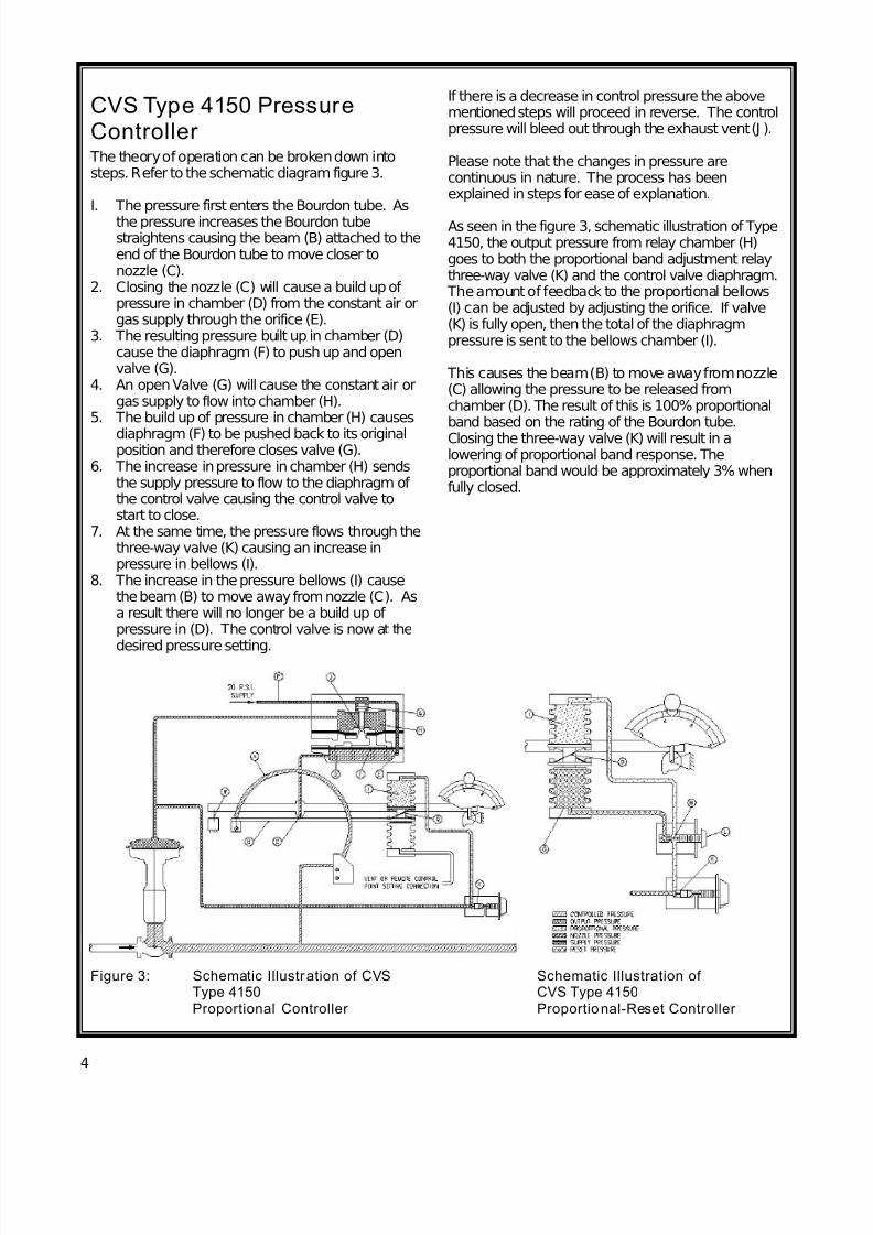
The theory of operation can be broken down intosteps. Refer to the schematic diagram figure 3.
I. The pressure first enters the Bourdon tube. Asthe pressure increases the Bourdon tubestraightens causing the beam (B) attached to theend of the Bourdon tube to move closer tonozzle (C).
2. Closing the nozzle (C) will cause a build up of pressure in chamber (D) from the constant air orgas supply through the orifice (E).
3. The resulting pressure built up in chamber (D)cause the diaphragm (F) to push up and openvalve (G).
4. An open Valve (G) will cause the constant air orgas supply to flow into chamber (H).
5. The build up of pressure in chamber (H) causes
diaphragm (F) to be pushed back to its originalposition and therefore closes valve (G).
6. The increase in pressure in chamber (H) sendsthe supply pressure to flow to the diaphragm of the control valve causing the control valve tostart to close.
7. At the same time, the pressure flows through thethree-way valve (K) causing an increase inpressure in bellows (I).
8. The increase in the pressure bellows (I) causethe beam (B) to move away from nozzle (C). Asa result there will no longer be a build up of pressure in (D). The control valve is now at the
desired pressure setting.
Figure 3: Schematic Illustration of CVSType 4150
Proportional Controller
Schematic Illustration of CVS Type 4150
Proportional-Reset Controller
If there is a decrease in control pressure the abovementioned steps will proceed in reverse. The controlpressure will bleed out through the exhaust vent (J ).
Please note that the changes in pressure arecontinuous in nature. The process has beenexplained in steps for ease of explanation.
As seen in the figure 3, schematic illustration of Type4150, the output pressure from relay chamber (H)goes to both the proportional band adjustment relaythree-way valve (K) and the control valve diaphragm.
The amount of feedback to the proportional bellows(I) can be adjusted by adjusting the orifice. If valve(K) is fully open, then the total of the diaphragmpressure is sent to the bellows chamber (I).
This causes the beam (B) to move away from nozzle(C) allowing the pressure to be released fromchamber (D). The result of this is 100% proportionalband based on the rating of the Bourdon tube.Closing the three-way valve (K) will result in alowering of proportional band response. Theproportional band would be approximately 3% whenfully closed.
7/28/2019 controlador 4160
http://slidepdf.com/reader/full/controlador-4160 5/12
5
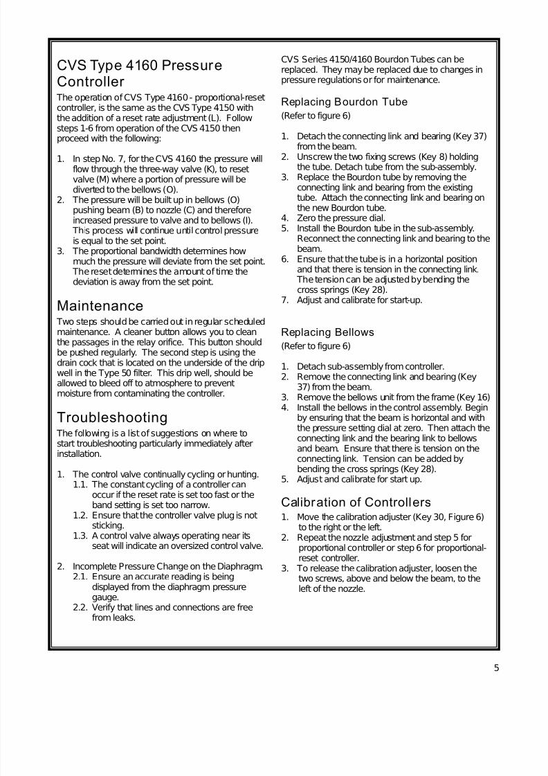
CVS Type 4160 PressureController
The operation of CVS Type 4160 - proportional-resetcontroller, is the same as the CVS Type 4150 withthe addition of a reset rate adjustment (L). Followsteps 1-6 from operation of the CVS 4150 then
proceed with the following:
1. In step No. 7, for the CVS 4160 the pressure willflow through the three-way valve (K), to resetvalve (M) where a portion of pressure will bediverted to the bellows (O).
2. The pressure will be built up in bellows (O)pushing beam (B) to nozzle (C) and thereforeincreased pressure to valve and to bellows (I).
This process will continue until control pressureis equal to the set point.
3. The proportional bandwidth determines howmuch the pressure will deviate from the set point.
The reset determines the amount of time thedeviation is away from the set point.
Maintenance Two steps should be carried out in regular scheduledmaintenance. A cleaner button allows you to cleanthe passages in the relay orifice. This button shouldbe pushed regularly. The second step is using thedrain cock that is located on the underside of the dripwell in the Type 50 filter. This drip well, should beallowed to bleed off to atmosphere to preventmoisture from contaminating the controller.
Troubleshooting The following is a list of suggestions on where tostart troubleshooting particularly immediately afterinstallation.
1. The control valve continually cycling or hunting.1.1. The constant cycling of a controller can
occur if the reset rate is set too fast or theband setting is set too narrow.
1.2. Ensure that the controller valve plug is notsticking.
1.3. A control valve always operating near its
seat will indicate an oversized control valve.
2. Incomplete Pressure Change on the Diaphragm.2.1. Ensure an accurate reading is being
displayed from the diaphragm pressuregauge.
2.2. Verify that lines and connections are freefrom leaks.
CVS Series 4150/4160 Bourdon Tubes can bereplaced. They may be replaced due to changes inpressure regulations or for maintenance.
Replacing Bourdon Tube
(Refer to figure 6)
1. Detach the connecting link and bearing (Key 37)from the beam.
2. Unscrew the two fixing screws (Key 8) holdingthe tube. Detach tube from the sub-assembly.
3. Replace the Bourdon tube by removing theconnecting link and bearing from the existingtube. Attach the connecting link and bearing onthe new Bourdon tube.
4. Zero the pressure dial.5. Install the Bourdon tube in the sub-assembly.
Reconnect the connecting link and bearing to thebeam.
6. Ensure that the tube is in a horizontal position
and that there is tension in the connecting link. The tension can be adjusted by bending thecross springs (Key 28).
7. Adjust and calibrate for start-up.
Replacing Bellows
(Refer to figure 6)
1. Detach sub-assembly from controller.2. Remove the connecting link and bearing (Key
37) from the beam.3. Remove the bellows unit from the frame (Key 16)
4. Install the bellows in the control assembly. Beginby ensuring that the beam is horizontal and withthe pressure setting dial at zero. Then attach theconnecting link and the bearing link to bellowsand beam. Ensure that there is tension on theconnecting link. Tension can be added bybending the cross springs (Key 28).
5. Adjust and calibrate for start up.
Calibration of Controllers1. Move the calibration adjuster (Key 30, Figure 6)
to the right or the left.2. Repeat the nozzle adjustment and step 5 for
proportional controller or step 6 for proportional-reset controller.
3. To release the calibration adjuster, loosen thetwo screws, above and below the beam, to theleft of the nozzle.
7/28/2019 controlador 4160
http://slidepdf.com/reader/full/controlador-4160 6/12
6
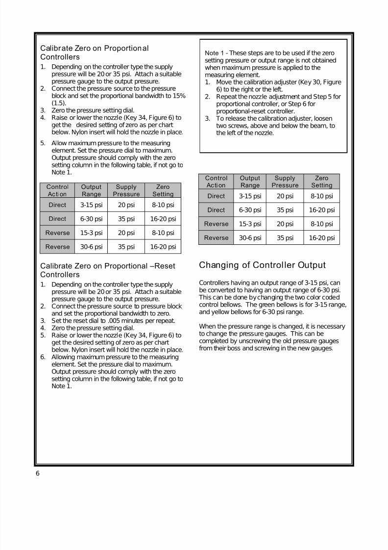
Calibrate Zero on ProportionalControllers
1. Depending on the controller type the supplypressure will be 20 or 35 psi. Attach a suitablepressure gauge to the output pressure.
2. Connect the pressure source to the pressure
block and set the proportional bandwidth to 15%(1.5).
3. Zero the pressure setting dial.4. Raise or lower the nozzle (Key 34, Figure 6) to
get the desired setting of zero as per chartbelow. Nylon insert will hold the nozzle in place.
5. Allow maximum pressure to the measuringelement. Set the pressure dial to maximum.Output pressure should comply with the zerosetting column in the following table, if not go toNote 1.
Control
Action
Output
Range
Supply
Pressure
Zero
Setting
Direct 3-15 psi 20 psi 8-10 psi
Direct 6-30 psi 35 psi 16-20 psi
Reverse 15-3 psi 20 psi 8-10 psi
Reverse 30-6 psi 35 psi 16-20 psi
Calibrate Zero on Proportional –ResetControllers
1. Depending on the controller type the supplypressure will be 20 or 35 psi. Attach a suitablepressure gauge to the output pressure.
2. Connect the pressure source to pressure blockand set the proportional bandwidth to zero.
3. Set the reset dial to .005 minutes per repeat.4. Zero the pressure setting dial.5. Raise or lower the nozzle (Key 34, Figure 6) to
get the desired setting of zero as per chartbelow. Nylon insert will hold the nozzle in place.
6. Allowing maximum pressure to the measuringelement. Set the pressure dial to maximum.Output pressure should comply with the zerosetting column in the following table, if not go to
Note 1.
Note 1 - These steps are to be used if the zerosetting pressure or output range is not obtainedwhen maximum pressure is applied to themeasuring element.1. Move the calibration adjuster (Key 30, Figure
6) to the right or the left.
2. Repeat the nozzle adjustment and Step 5 forproportional controller, or Step 6 forproportional-reset controller.
3. To release the calibration adjuster, loosentwo screws, above and below the beam, tothe left of the nozzle.
Control Action
OutputRange
SupplyPressure
ZeroSetting
Direct 3-15 psi 20 psi 8-10 psi
Direct 6-30 psi 35 psi 16-20 psi
Reverse 15-3 psi 20 psi 8-10 psi
Reverse 30-6 psi 35 psi 16-20 psi
Changing of Control ler Output
Controllers having an output range of 3-15 psi, can
be converted to having an output range of 6-30 psi. This can be done by changing the two color codedcontrol bellows. The green bellows is for 3-15 range,and yellow bellows for 6-30 psi range.
When the pressure range is changed, it is necessaryto change the pressure gauges. This can becompleted by unscrewing the old pressure gaugesfrom their boss and screwing in the new gauges.
7/28/2019 controlador 4160
http://slidepdf.com/reader/full/controlador-4160 7/12
7
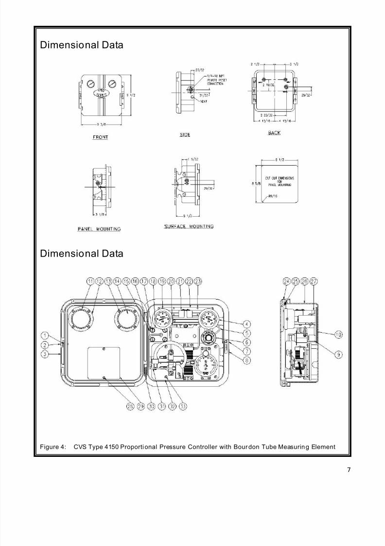
Dimensional Data
Dimensional Data
Figure 4: CVS Type 4150 Proportional Pressure Controller with Bourdon Tube Measuring Element
7/28/2019 controlador 4160
http://slidepdf.com/reader/full/controlador-4160 8/12
8
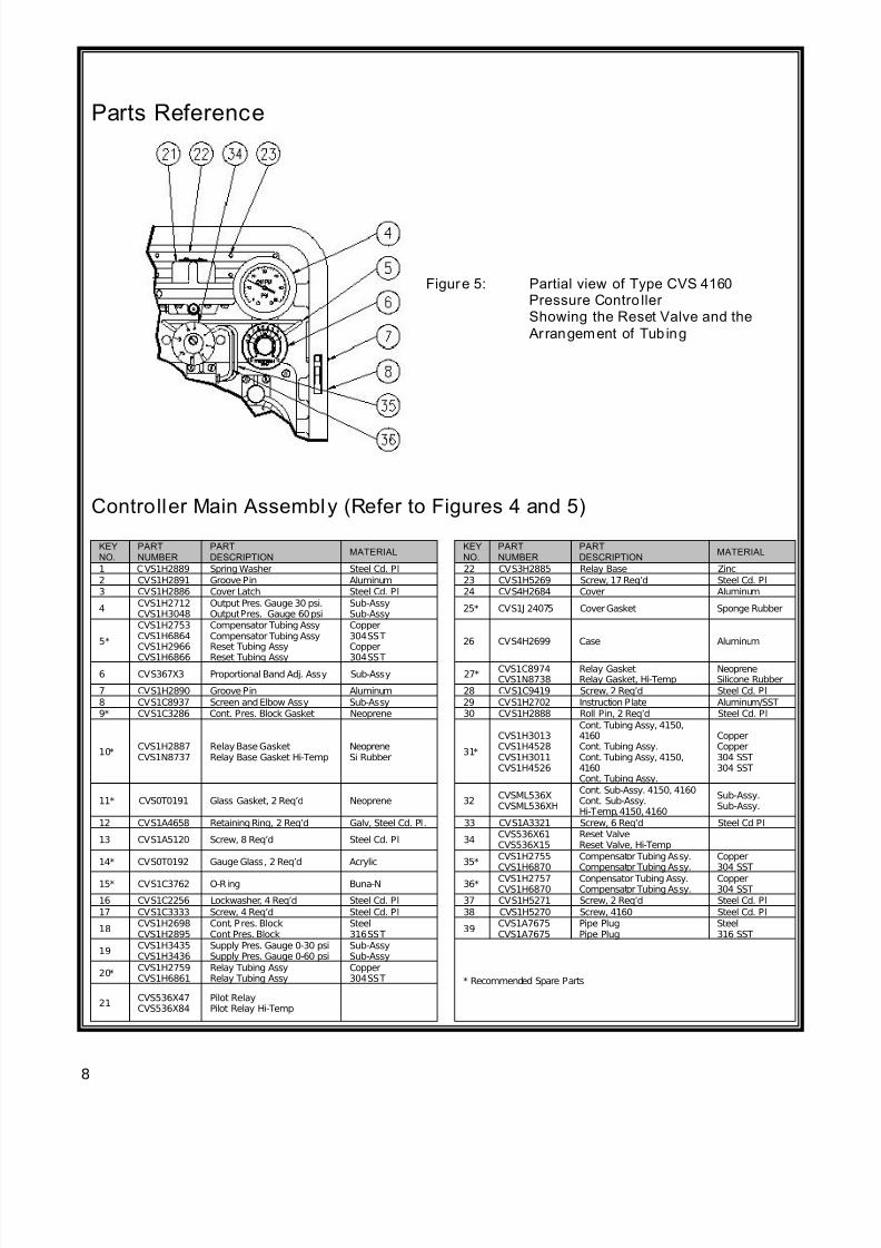
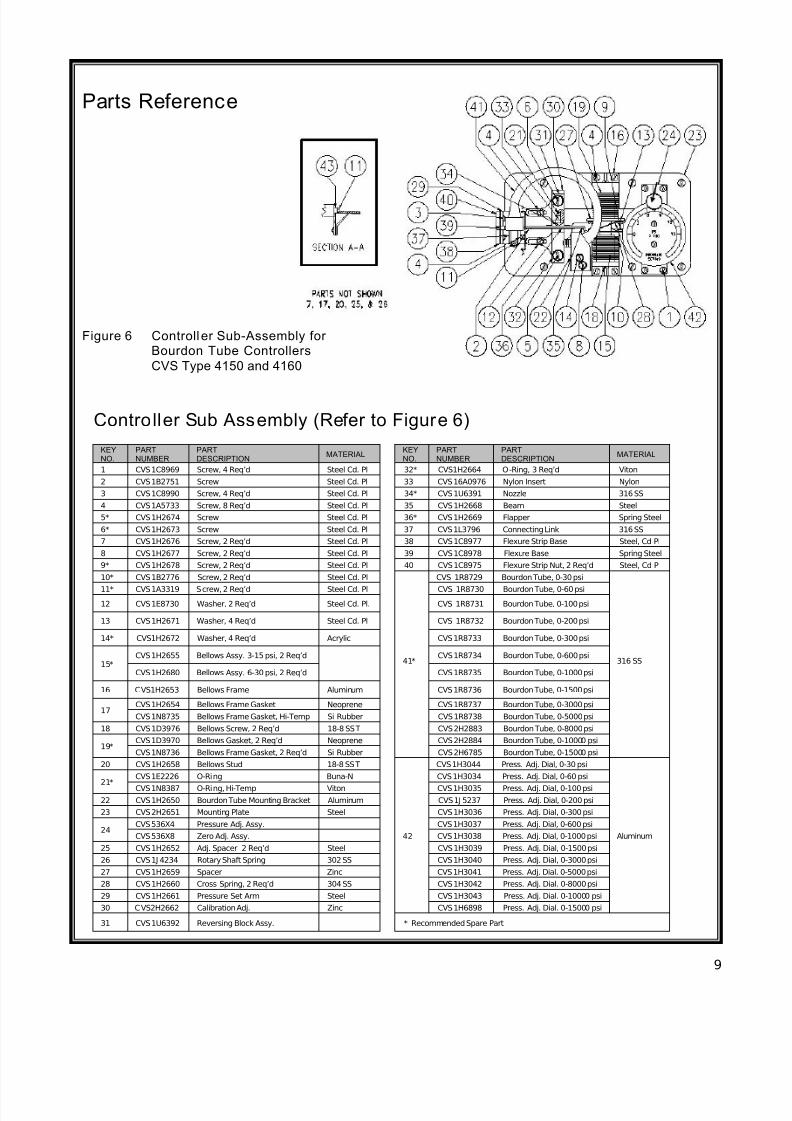
Parts Reference
Figure 5: Partial view of Type CVS 4160Pressure Contro ller Showing the Reset Valve and the
Arrangement of Tub ing
Controller Main Assembly (Refer to Figures 4 and 5)
KEYNO.
PARTNUMBER
PARTDESCRIPTION
MATERIALKEYNO.
PARTNUMBER
PARTDESCRIPTION
MATERIAL
1 CVS1H2889 Spring Washer Steel Cd. Pl 22 CVS3H2885 Relay Base Zinc
2 CVS1H2891 Groove Pin Aluminum 23 CVS1H5269 Screw, 17 Req’d Steel Cd. Pl3 CVS1H2886 Cover Latch Steel Cd. Pl 24 CVS4H2684 Cover Aluminum
4CVS1H2712CVS1H3048
Output Pres. Gauge 30 psi.Output Pres. Gauge 60 psi
Sub-AssySub-Assy
25* CVS1J 24075 Cover Gasket Sponge Rubber
5*
CVS1H2753CVS1H6864CVS1H2966
CVS1H6866
Compensator Tubing AssyCompensator Tubing AssyReset Tubing Assy
Reset Tubing Assy
Copper304 SSTCopper
304 SST
26 CVS4H2699 Case Aluminum
6 CVS367X3 Proportional Band Adj. Assy Sub-Assy 27*CVS1C8974CVS1N8738
Relay GasketRelay Gasket, Hi-Temp
NeopreneSilicone Rubber
7 CVS1H2890 Groove Pin Aluminum 28 CVS1C9419 Screw, 2 Req’d Steel Cd. Pl
8 CVS1C8937 Screen and Elbow Assy Sub-Assy 29 CVS1H2702 Instruction Plate Aluminum/SST9* CVS1C3286 Cont. Pres. Block Gasket Neoprene 30 CVS1H2888 Roll Pin, 2 Req’d Steel Cd. Pl
10*CVS1H2887CVS1N8737
Relay Base GasketRelay Base Gasket Hi-Temp
NeopreneSi Rubber
31*
CVS1H3013CVS1H4528CVS1H3011CVS1H4526
Cont. Tubing Assy, 4150,4160Cont. Tubing Assy.Cont. Tubing Assy, 4150,4160Cont. Tubing Assy.
CopperCopper304 SST304 SST
11* CVS0T0191 Glass Gasket, 2 Req’d Neoprene 32CVSML536XCVSML536XH
Cont. Sub-Assy. 4150, 4160Cont. Sub-Assy.Hi-Temp, 4150, 4160
Sub-Assy.Sub-Assy.
12 CVS1A4658 Retaining Ring, 2 Req’d Galv, Steel Cd. Pl. 33 CVS1A3321 Screw, 6 Req’d Steel Cd Pl
13 CVS1A5120 Screw, 8 Req’d Steel Cd. Pl 34CVS536X61CVS536X15
Reset ValveReset Valve, Hi-Temp
14* CVS0T0192 Gauge Glass, 2 Req’d Acrylic 35*CVS1H2755CVS1H6870
Compensator Tubing Assy.Compensator Tubing Assy.
Copper304 SST
15* CVS1C3762 O-Ring Buna-N 36*CVS1H2757CVS1H6870
Conpensator Tubing Assy.Compensator Tubing Assy.
Copper304 SST
16 CVS1C2256 Lockwasher, 4 Req’d Steel Cd. Pl 37 CVS1H5271 Screw, 2 Req’d Steel Cd. Pl
17 CVS1C3333 Screw, 4 Req’d Steel Cd. Pl 38 CVS1H5270 Screw, 4160 Steel Cd. Pl
18CVS1H2698CVS1H2895
Cont. Pres. BlockCont Pres. Block
Steel316 SST
39CVS1A7675CVS1A7675
Pipe PlugPipe Plug
Steel316 SST
19CVS1H3435CVS1H3436
Supply Pres. Gauge 0-30 psiSupply Pres. Gauge 0-60 psi
Sub-AssySub-Assy
* Recommended Spare Parts20*
CVS1H2759CVS1H6861
Relay Tubing AssyRelay Tubing Assy
Copper304 SST
21CVS536X47CVS536X84
Pilot RelayPilot Relay Hi-Temp
7/28/2019 controlador 4160
http://slidepdf.com/reader/full/controlador-4160 9/12
9
Parts Reference
Controller Sub Assembly (Refer to Figure 6)
KEYNO.
PARTNUMBER
PARTDESCRIPTION
MATERIALKEYNO.
PARTNUMBER
PARTDESCRIPTION
MATERIAL
1 CVS1C8969 Screw, 4 Req’d Steel Cd. Pl 32* CVS1H2664 O-Ring, 3 Req’d Viton
2 CVS1B2751 Screw Steel Cd. Pl 33 CVS16A0976 Nylon Insert Nylon
3 CVS1C8990 Screw, 4 Req’d Steel Cd. Pl 34* CVS1U6391 Nozzle 316 SS
4 CVS1A5733 Screw, 8 Req’d Steel Cd. Pl 35 CVS1H2668 Beam Steel
5* CVS1H2674 Screw Steel Cd. Pl 36* CVS1H2669 Flapper Spring Steel
6* CVS1H2673 Screw Steel Cd. Pl 37 CVS1L3796 Connecting Link 316 SS
7 CVS1H2676 Screw, 2 Req’d Steel Cd. Pl 38 CVS1C8977 Flexure Strip Base Steel, Cd Pl
8 CVS1H2677 Screw, 2 Req’d Steel Cd. Pl 39 CVS1C8978 Flexure Base Spring Steel
9* CVS1H2678 Screw, 2 Req’d Steel Cd. Pl 40 CVS1C8975 Flexure Strip Nut, 2 Req’d Steel, Cd Pl
10* CVS1B2776 Screw, 2 Req’d Steel Cd. Pl
41*
CVS 1R8729 Bourdon Tube, 0-30 psi
316 SS
11* CVS1A3319 Screw, 2 Req’d Steel Cd. Pl CVS 1R8730 Bourdon Tube, 0-60 psi
12 CVS1E8730 Washer, 2 Req’d Steel Cd. Pl. CVS 1R8731 Bourdon Tube, 0-100 psi
13 CVS1H2671 Washer, 4 Req’d Steel Cd. Pl CVS 1R8732 Bourdon Tube, 0-200 psi
14* CVS1H2672 Washer, 4 Req’d Acrylic CVS1R8733 Bourdon Tube, 0-300 psi
15*CVS1H2655 Bellows Assy. 3-15 psi, 2 Req’d CVS1R8734 Bourdon Tube, 0-600 psi
CVS1H2680 Bellows Assy. 6-30 psi, 2 Req’d CVS1R8735 Bourdon Tube, 0-1000 psi
16 CVS1H2653 Bellows Frame Aluminum CVS1R8736 Bourdon Tube, 0-1500 psi
17CVS1H2654 Bellows Frame Gasket Neoprene CVS1R8737 Bourdon Tube, 0-3000 psi
CVS1N8735 Bellows Frame Gasket, Hi-Temp Si Rubber CVS1R8738 Bourdon Tube, 0-5000 psi
18 CVS1D3976 Bellows Screw, 2 Req’d 18-8 SST CVS2H2883 Bourdon Tube, 0-8000 psi
19*CVS1D3970 Bellows Gasket, 2 Req’d Neoprene CVS2H2884 Bourdon Tube, 0-10000 psi
CVS1N8736 Bellows Frame Gasket, 2 Req’d Si Rubber CVS2H6785 Bourdon Tube, 0-15000 psi
20 CVS1H2658 Bellows Stud 18-8 SST
42
CVS1H3044 Press. Adj. Dial, 0-30 psi
Aluminum
21*
CVS1E2226 O-Ring Buna-N CVS1H3034 Press. Adj. Dial, 0-60 psi
CVS1N8387 O-Ring, Hi-Temp Viton CVS1H3035 Press. Adj. Dial, 0-100 psi
22 CVS1H2650 Bourdon Tube Mounting Bracket Aluminum CVS1J 5237 Press. Adj. Dial, 0-200 psi
23 CVS2H2651 Mounting Plate Steel CVS1H3036 Press. Adj. Dial, 0-300 psi
24CVS536X4 Pressure Adj. Assy. CVS1H3037 Press. Adj. Dial, 0-600 psi
CVS536X8 Zero Adj. Assy. CVS1H3038 Press. Adj. Dial, 0-1000 psi
25 CVS1H2652 Adj. Spacer 2 Req’d Steel CVS1H3039 Press. Adj. Dial, 0-1500 psi
26 CVS1J 4234 Rotary Shaft Spring 302 SS CVS1H3040 Press. Adj. Dial, 0-3000 psi
27 CVS1H2659 Spacer Zinc CVS1H3041 Press. Adj. Dial. 0-5000 psi
28 CVS1H2660 Cross Spring, 2 Req’d 304 SS CVS1H3042 Press. Adj. Dial. 0-8000 psi
29 CVS1H2661 Pressure Set Arm Steel CVS1H3043 Press. Adj. Dial. 0-10000 psi
30 CVS2H2662 Calibration Adj. Zinc CVS1H6898 Press. Adj. Dial. 0-15000 psi
31 CVS1U6392 Reversing Block Assy. * Recommended Spare Part
Figure 6 Controller Sub-Assembly for Bourdon Tube Controllers
CVS Type 4150 and 4160
7/28/2019 controlador 4160
http://slidepdf.com/reader/full/controlador-4160 10/12
10
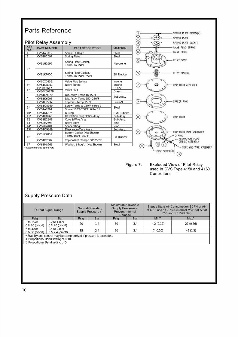
Parts Reference
Pilot Relay AssemblyKEYNO.
PART NUMBER PART DESCRIPTION MATERIAL
1 CVS1A3319 Screw, 4 Req’d Steel
2 CVS1H2697 Spring Plate Steel
3*
CVS1H2696Spring Plate Gasket, Temp. To 150°F
Neoprene
CVS1K7000Spring Plate Gasket, Temp. To 150°F-250°F
Sil. Rubber
4 CVS0X0836 Valve Plug Spring Inconel
5* CVS1C8961 Relay Spring Inconel
6*CVS0Y0617
Valve Plug316 SS
CVS0Y0617B Brass
7CVS1C9370 Dia. Assy. Temp To 150°F
Sub Assy.CVS1K6996 Dia. Assy. Temp 150°-250°F
8 CVS1L5556 Top Dia., Temp 150°F Buna-N
9*CVS1C8969 Screw Temp to 150°F 6 Req’d
SteelCVS1A3294 Screw 150°F-250°F 6 Req’d
10* CVS1D6875 O-Ring Syn. Rubber11* CVS1H8266 Restriction Plug Orifice Assy. Sub Assy.
12 CVS1E2303 Core & Wire Assy. Sub Assy.
13 CVS2H2693 Relay Body Zinc
14* CVS2K4404 Spacer Ring Zinc15* CVS1C9369 Diaphragm Case Assy Sub Assy.
16CVS1K7001
Bottom Gasket (Not Shown) Temp. 150°F-250°F Sil. Rubber
CVS1K7002 Top Gasket, Temp 150°-250°F
17 CVS1P8261 Washer, 6 Req’d (Not Shown) Steel* Recommended Spare Part
Output Signal RangeNormal Operating
Supply Pressure (*)
Maximum AllowableSupply Pressure to
Prevent InternalDamage
Steady State Air Consumption SCFH of Air at 60°F and 14.7PSIA (Normal M3/Hr of Air at
0°C and 1.01325 Bar)
Psig Bar Psig Bar Psig Bar Min Max
3 to 15 or0 & 20 (on-off)
0.2 to 1.0 or0 & 20 (on-off)
20 1.4 50 3.4 4.2 (0.12) 27 (0.76)
6 to 30 or0 & 30 (on-off)
0.4 to 2.0 or0 & 2.4 (on-off)
35 2.4 50 3.4 7 (0.20) 42 (1.2)
* Stability and control may be compromised if pressure is exceeded.A Proportional Band setting of 0-10B Proportional Band setting of 5
Supply Pressure Data
Figure 7: Exploded View of Pilot Relayused in CVS Type 4150 and 4160
Controllers
7/28/2019 controlador 4160
http://slidepdf.com/reader/full/controlador-4160 11/12
11
Specifications
Supply:
Air or Natural Gas**natural gas should contain no more than 20ppm of Hydrogen Sulphide
Supply and Output Connections:
1/4" NPT Female
Supply Pressure:
-Normal operating pressure for 3 to 15 psig outputsignal range is 20 psig.
-Normal operating pressure for 6 to 30 psig outputsignal range is 35 psig.
Operating Temperature Limit s:
-40oF to 200
oF (-40
oC to 93
oC)*
*Standard Construction
Operating Temperature Infl uence:
-Proportional Control:Output pressure changes ±3% of sensing elementrange for each 50
oF (28
oC) change in temperature
between -40oF and 160
oF (-40
oC and 71
oC) if the
controller is set at 100% proportional band.
-Reset Control:
Output pressure changes ±2% of sensing elementrange for each 50oF (28
oC) change in temperature
between -40oF and 160
oF (-40
oC and 71
oC) if the
controller is set at 100% proportional band.
Performance:
-Repeatability:0.5% of sensing element range
-Deadband:0.1% of output span
-Frequency response at 100% proportional band:Output to actuator: 0.7 Hz and 110o phase shift with113 inches
3(1850 cm
3) volume, actuator at mid
stroke.
Output to positioner bellows: 9 Hz and 130ophase
shift with 3 -15 psig (0.2 to 1.0 bar) output to 2inches
3(33cm
3) bellows.
Output Signal:
3 to 15 psig (0.2 to 1.0 bar) or 6 to 30 psig (0.4 to2.0 bar) pneumatic pressure signal.
Action:
The control action is easily reversible fromdirectacting (increasing sensed pressure producesincreasing output signal) to reverse acting (increasing sensed pressure produces decreasingoutput signal) without the need for additional parts.
Proportional Band Adjustment:
Full output pressure change is adjustable from 3 to100% for a 3 to 15 psig (0.2 to 1.0 bar), or 6 to 100%for a 6 to 30 psig (0.4 to 2.0 bar) of the sensing
element range.
Reset Adjustment:
Adjustable from 0.01 to 74 minutes per repeat(100 to 0.01 repeats per minute)
7/28/2019 controlador 4160
http://slidepdf.com/reader/full/controlador-4160 12/12
12
Head Office
3900 – 101 StreetEdmonton, Alberta, Canada T6E 0A5
Office: (780) 437-3055Fax: (780) 436-5461
Website: www.cvs-controls.com E-Mail: [email protected]
Calgary Sales Office205, 2323 – 32 Avenue NE
Calgary, Alberta, Canada T2E 6Z3Office: (403) 250-1416Fax: (403) 291-9487
Rev 1, J uly 2012