corporate member of csa - emiratesgbc |...
TRANSCRIPT
International Operations Business Group
Corporate Member of CSA
REEF TECH SERVICES
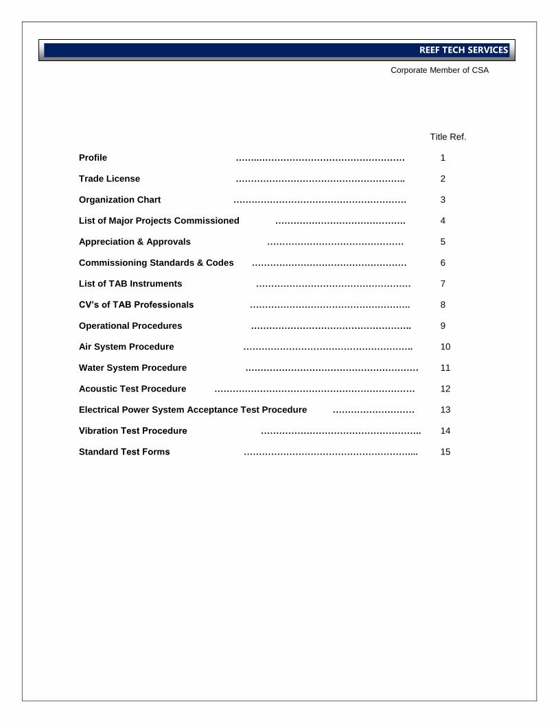
Title Ref. Profile ……..………………………………………… 1 Trade License ……………………………………………….. 2 Organization Chart ………………………………………………… 3 List of Major Projects Commissioned ……………………………………. 4 Appreciation & Approvals ……………………………………… 5 Commissioning Standards & Codes …………………………………………… 6 List of TAB Instruments …………………………………………… 7 CV’s of TAB Professionals …………………………………………….. 8 Operational Procedures …………………………………………….. 9 Air System Procedure ……………………………………………….. 10 Water System Procedure ………………………………………………… 11 Acoustic Test Procedure ………………………………………………………… 12 Electrical Power System Acceptance Test Procedure ……………………… 13 Vibration Test Procedure …………………………………………….. 14 Standard Test Forms ……………………………………………….... 15

International Operations Business Group
Corporate Member of CSA
REEF TECH SERVICES
Commissioning Solutions towards Sustainable, Energy - Efficient
Building Performance
Introduction
The commissioning phase of any project is often key to the sustainable, comfort and
environmental, performance of a building, vis-à-vis the system design.
It is well known that over the life of the equipment, just the energy cost of operating and
maintaining present building HVAC services are 5 to 10 times the total equipment cost.
Hence the importance of focused design and commissioning portfolios cannot be
overstressed.
Reef Tech Services L.L.C. acknowledges its responsibilities in this regard and has set
standards which will easily maintain the high standards expected by the building services
industry in the UAE.
Our aims are primarily to meet the ever growing commercial demand for practical
experience and professional expertise within this sector.
Reef Tech Services L.L.C. has been formed to provide this specialized, quick, efficient,
reliable, and flexible and cost- effective technical service to the Building Services
Contracting and Consultancy fields. We also offer a wide range of other services including,
Validation and Site Surveys, Energy Surveys, Sound Level Measurement, and Technical
Documentation.
We achieve this by providing a pro-active service with open channels of communication with
our clients.
In order to satisfy these demands, we are led by a dedicated engineering team with a
combined experience of 25 years in installation, commissioning, operation and
maintenance of building HVAC services and equipment.
Time and again during our validation and site surveys, especially, in refurbishment and
renovation projects, we have been instrumental in assisting the design team and contractor
to correctly select equipment, according to site conditions, in order to provide optimum
performance for the client.
All of our personnel are skilled, with industry accreditation as their foundation. We are a
member of Commissioning Specialist Association (CSA) in the United Kingdom as the
principal body ensuring high standards within this industry worldwide. Our activities are
also guided by the recognized commissioning standards and codes of practice as laid down
by BSRIA and CIBSE (UK) and AACB (USA).
The company focus and purpose is to fortify its ability to respond quickly and efficiently to
fast track projects, and to the increasingly sophisticated plant, equipment and design
schemes typically being provided for the innovative and multicultural building projects in
this area.
From order placement to practical demonstration of system performance, we are committed
to provide the highest degree of professional response. All Our method statements and
plans are prepared by well qualified and experienced staffs, which consist of detailed
explanation and procedure to meet specification and project requirement.
International Operations Business Group
Corporate Member of CSA
REEF TECH SERVICES
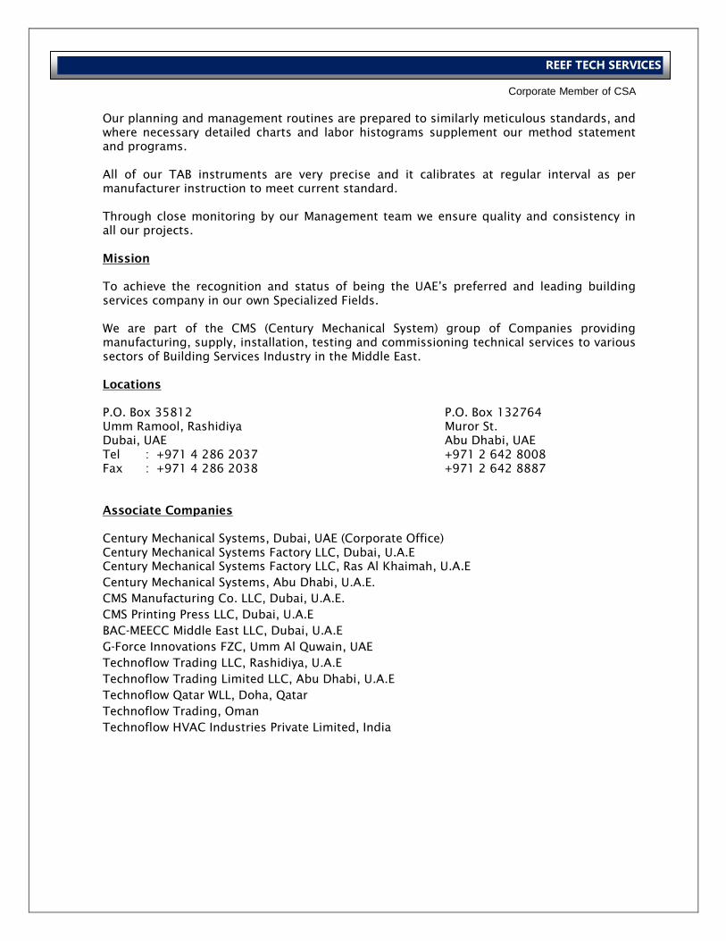
Our planning and management routines are prepared to similarly meticulous standards, and
where necessary detailed charts and labor histograms supplement our method statement
and programs.
All of our TAB instruments are very precise and it calibrates at regular interval as per
manufacturer instruction to meet current standard.
Through close monitoring by our Management team we ensure quality and consistency in
all our projects.
Mission
To achieve the recognition and status of being the UAE’s preferred and leading building
services company in our own Specialized Fields.
We are part of the CMS (Century Mechanical System) group of Companies providing
manufacturing, supply, installation, testing and commissioning technical services to various
sectors of Building Services Industry in the Middle East.
Locations
P.O. Box 35812 P.O. Box 132764
Umm Ramool, Rashidiya Muror St.
Dubai, UAE Abu Dhabi, UAE
Tel : +971 4 286 2037 +971 2 642 8008
Fax : +971 4 286 2038 +971 2 642 8887
Associate Companies
Century Mechanical Systems, Dubai, UAE (Corporate Office)
Century Mechanical Systems Factory LLC, Dubai, U.A.E
Century Mechanical Systems Factory LLC, Ras Al Khaimah, U.A.E
Century Mechanical Systems, Abu Dhabi, U.A.E.
CMS Manufacturing Co. LLC, Dubai, U.A.E.
CMS Printing Press LLC, Dubai, U.A.E
BAC-MEECC Middle East LLC, Dubai, U.A.E
G-Force Innovations FZC, Umm Al Quwain, UAE
Technoflow Trading LLC, Rashidiya, U.A.E
Technoflow Trading Limited LLC, Abu Dhabi, U.A.E
Technoflow Qatar WLL, Doha, Qatar
Technoflow Trading, Oman
Technoflow HVAC Industries Private Limited, India
International Operations Business Group
Corporate Member of CSA
REEF TECH SERVICES
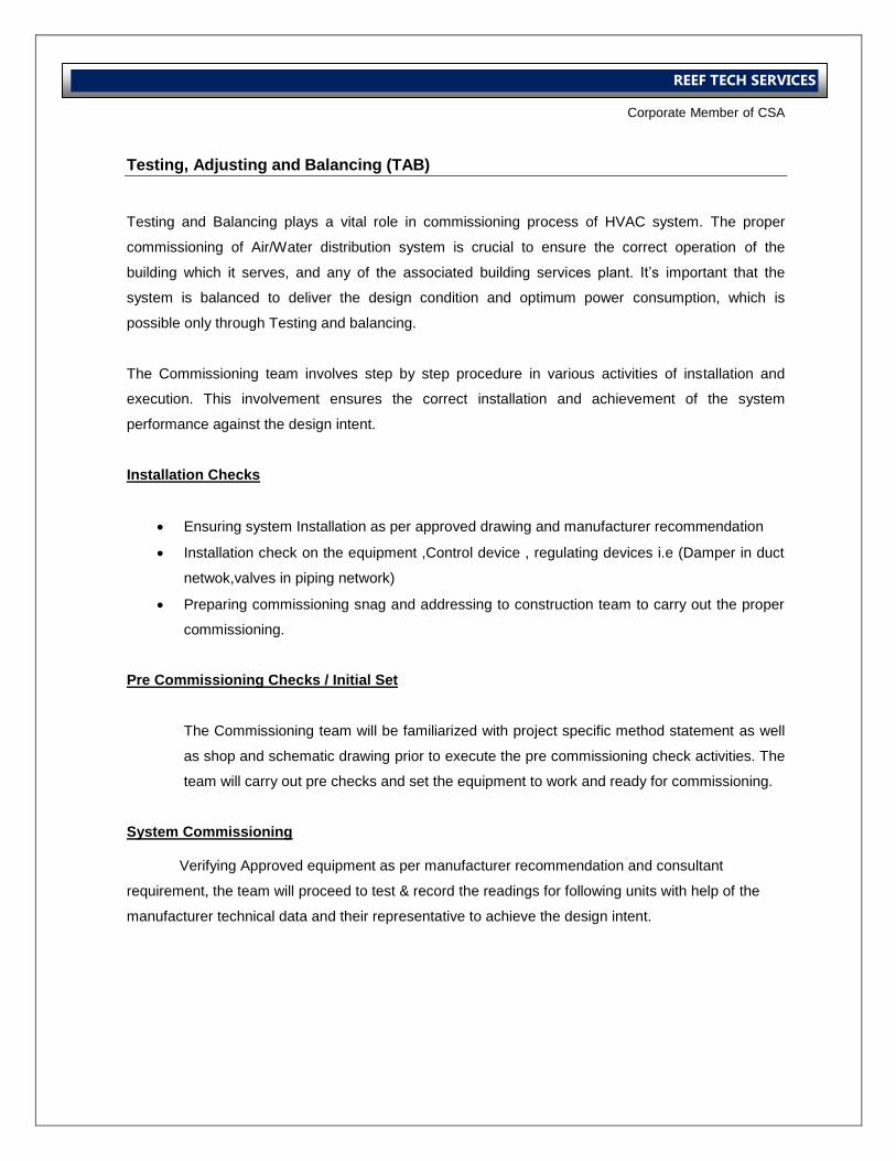
Testing, Adjusting and Balancing (TAB)
Testing and Balancing plays a vital role in commissioning process of HVAC system. The proper
commissioning of Air/Water distribution system is crucial to ensure the correct operation of the
building which it serves, and any of the associated building services plant. It’s important that the
system is balanced to deliver the design condition and optimum power consumption, which is
possible only through Testing and balancing.
The Commissioning team involves step by step procedure in various activities of installation and
execution. This involvement ensures the correct installation and achievement of the system
performance against the design intent.
Installation Checks
Ensuring system Installation as per approved drawing and manufacturer recommendation
Installation check on the equipment ,Control device , regulating devices i.e (Damper in duct
netwok,valves in piping network)
Preparing commissioning snag and addressing to construction team to carry out the proper
commissioning.
Pre Commissioning Checks / Initial Set
The Commissioning team will be familiarized with project specific method statement as well
as shop and schematic drawing prior to execute the pre commissioning check activities. The
team will carry out pre checks and set the equipment to work and ready for commissioning.
System Commissioning Verifying Approved equipment as per manufacturer recommendation and consultant
requirement, the team will proceed to test & record the readings for following units with help of the
manufacturer technical data and their representative to achieve the design intent.
International Operations Business Group
Corporate Member of CSA
REEF TECH SERVICES
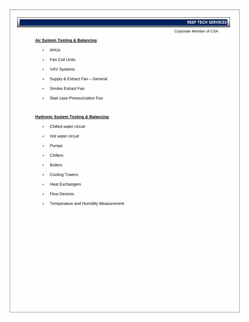
Air System Testing & Balancing
AHUs
Fan Coil Units
VAV Systems
Supply & Extract Fan – General
Smoke Extract Fan
Stair case Pressurization Fan
Hydronic System Testing & Balancing
Chilled water circuit
Hot water circuit
Pumps
Chillers
Boilers
Cooling Towers
Heat Exchangers
Flow Devices
Temperature and Humidity Measurement

International Operations Business Group
Corporate Member of CSA
REEF TECH SERVICES
International Operations Business Group
Corporate Member of CSA
REEF TECH SERVICES
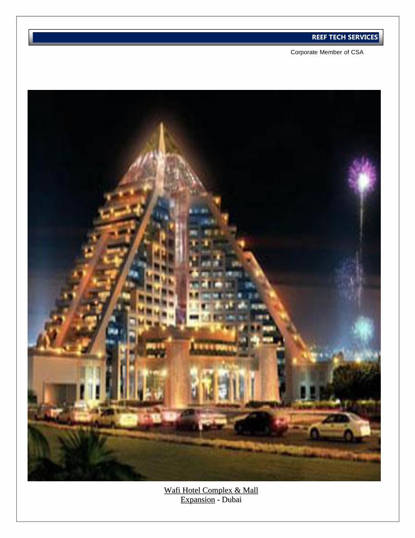
WWaaffii HHootteell CCoommpplleexx && MMaallll
EExxppaannssiioonn -- DDuubbaaii
International Operations Business Group
Corporate Member of CSA
REEF TECH SERVICES
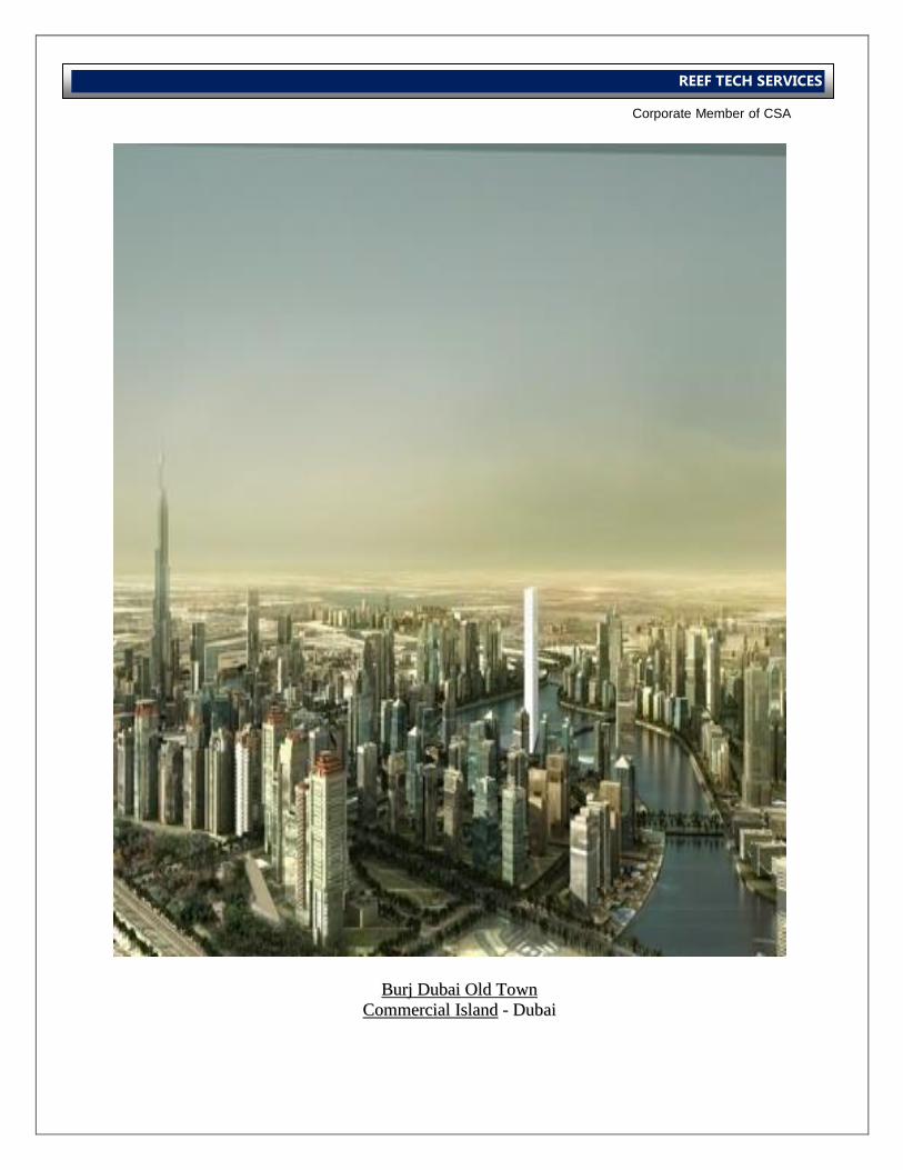
BBuurrjj DDuubbaaii OOlldd TToowwnn
CCoommmmeerrcciiaall IIssllaanndd -- DDuubbaaii
International Operations Business Group
Corporate Member of CSA
REEF TECH SERVICES
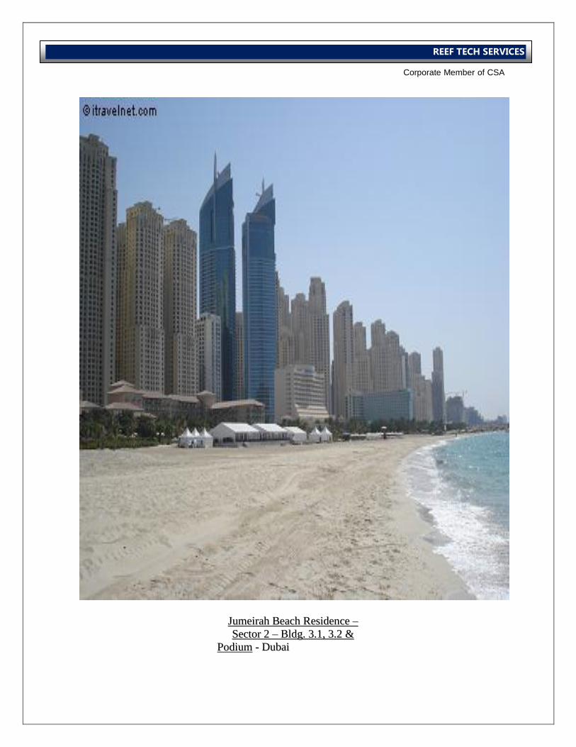
JJuummeeiirraahh BBeeaacchh RReessiiddeennccee ––
SSeeccttoorr 22 –– BBllddgg.. 33..11,, 33..22 &&
PPooddiiuumm -- DDuubbaaii
International Operations Business Group
Corporate Member of CSA
REEF TECH SERVICES
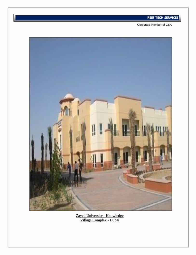
ZZaayyeedd UUnniivveerrssiittyy -- KKnnoowwlleeddggee
VViillllaaggee CCoommpplleexx -- DDuubbaaii
International Operations Business Group
Corporate Member of CSA
REEF TECH SERVICES
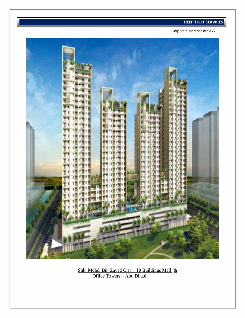
SShhkk.. MMoohhdd.. BBiinn ZZaayyeedd CCiittyy ––
1100 BBuuiillddiinnggss MMaallll &&
OOffffiiccee TToowweerrss –– AAbbuu DDhhaabbii
SShhkk.. MMoohhdd.. BBiinn ZZaayyeedd CCiittyy –– 1100 BBuuiillddiinnggss MMaallll &&
OOffffiiccee TToowweerrss –– AAbbuu DDhhaabbii
International Operations Business Group
Corporate Member of CSA
REEF TECH SERVICES
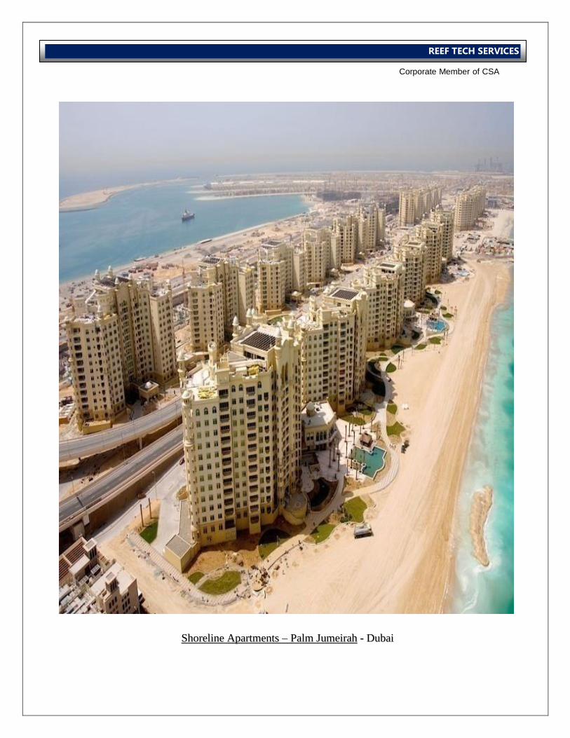
SShhoorreelliinnee AAppaarrttmmeennttss ––
PPaallmm JJuummeeiirraahh -- DDuubbaaii
SShhoorreelliinnee AAppaarrttmmeennttss –– PPaallmm JJuummeeiirraahh -- DDuubbaaii
International Operations Business Group
Corporate Member of CSA
REEF TECH SERVICES
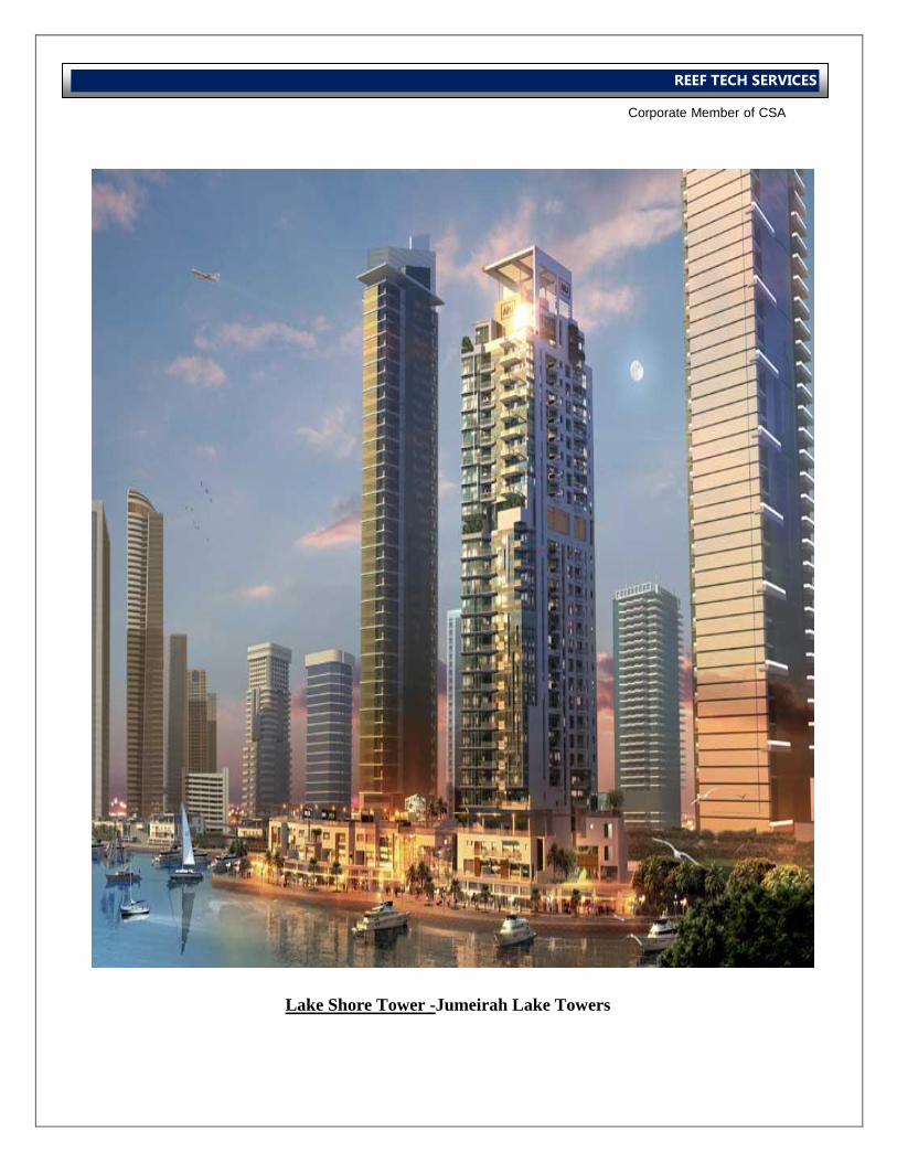
Lake Shore Tower -
Jumeirah Lake Towers
Lake Shore Tower -Jumeirah Lake Towers
International Operations Business Group
Corporate Member of CSA
REEF TECH SERVICES
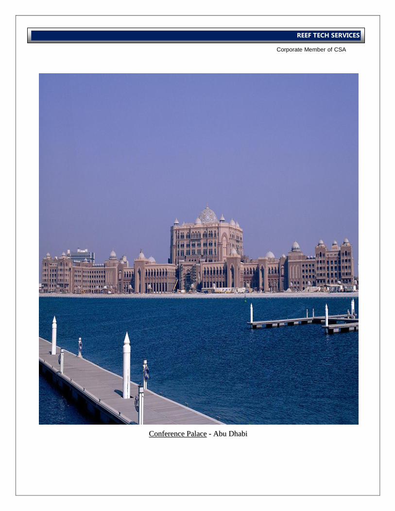
CCoonnffeerreennccee PPaallaaccee -- AAbbuu DDhhaabbii
CCoonnffeerreennccee PPaallaaccee -- AAbbuu DDhhaabbii
International Operations Business Group
Corporate Member of CSA
REEF TECH SERVICES
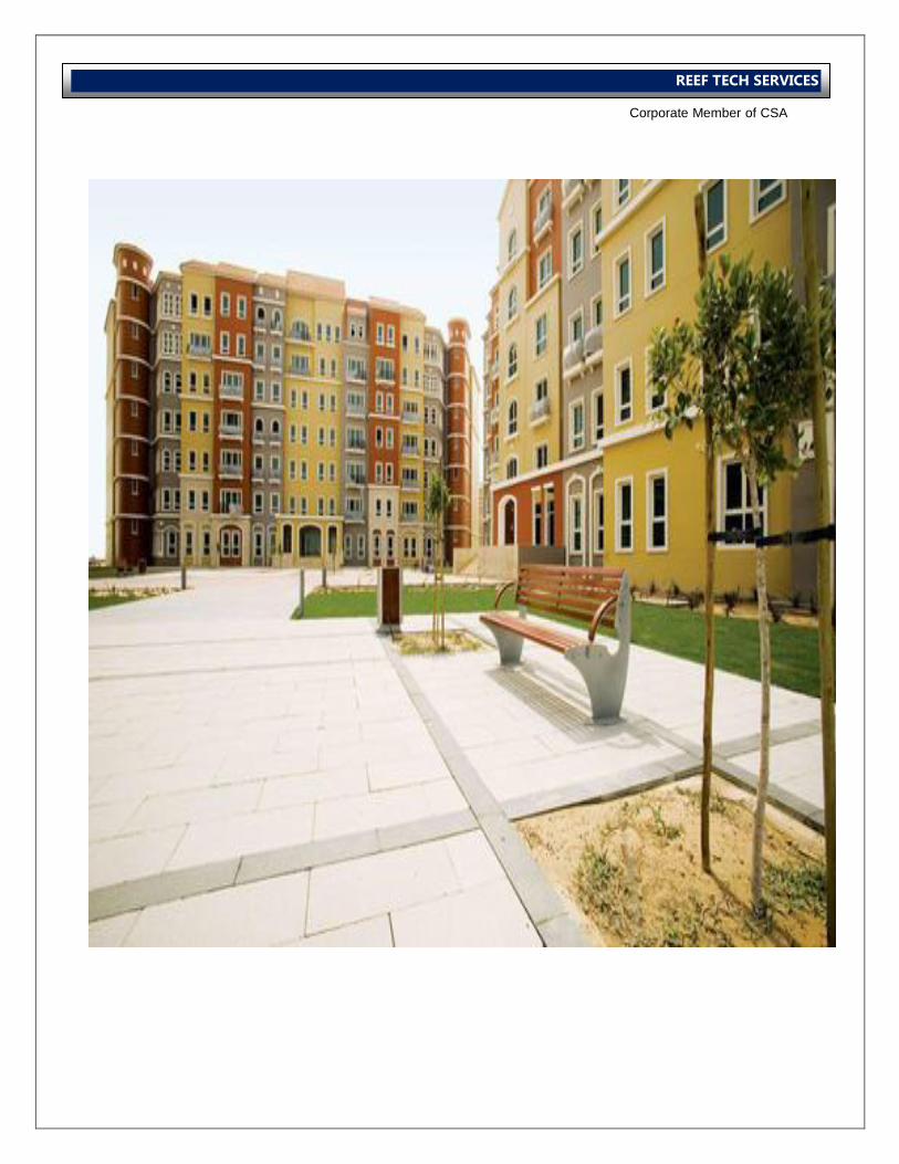
UUppttoowwnn DDeevveellooppmmeenntt
MMiirrddiiffff,, DDuubbaaii
UUppttoowwnn DDeevveellooppmmeenntt MMiirrddiiffff,, DDuubbaaii
International Operations Business Group
Corporate Member of CSA
REEF TECH SERVICES
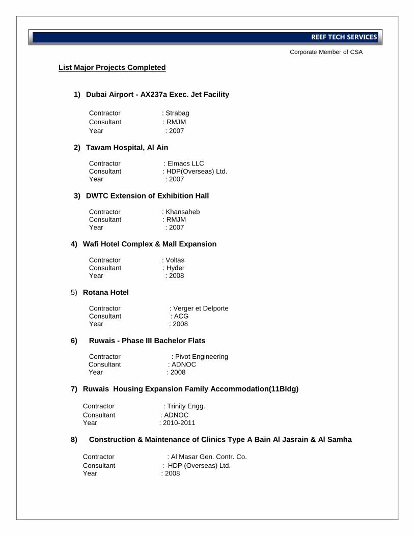
List Major Projects Completed
1) Dubai Airport - AX237a Exec. Jet Facility
Contractor : Strabag
Consultant : RMJM
Year : 2007
2) Tawam Hospital, Al Ain
Contractor : Elmacs LLC Consultant : HDP(Overseas) Ltd. Year : 2007
3) DWTC Extension of Exhibition Hall
Contractor : Khansaheb Consultant : RMJM Year : 2007
4) Wafi Hotel Complex & Mall Expansion
Contractor : Voltas Consultant : Hyder Year : 2008
5) Rotana Hotel
Contractor : Verger et Delporte Consultant : ACG Year : 2008
6) Ruwais - Phase III Bachelor Flats
Contractor : Pivot Engineering
Consultant : ADNOC Year : 2008
7) Ruwais Housing Expansion Family Accommodation(11Bldg)
Contractor : Trinity Engg.
Consultant : ADNOC Year : 2010-2011
8) Construction & Maintenance of Clinics Type A Bain Al Jasrain & Al Samha
Contractor : Al Masar Gen. Contr. Co.
Consultant : HDP (Overseas) Ltd. Year : 2008
International Operations Business Group
Corporate Member of CSA
REEF TECH SERVICES
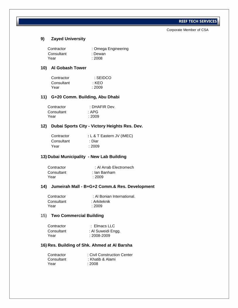
9) Zayed University
Contractor : Omega Engineering
Consultant : Dewan Year : 2008
10) Al Gobash Tower
Contractor : SEIDCO
Consultant : KEO Year : 2009
11) G+20 Comm. Building, Abu Dhabi
Contractor : DHAFIR Dev.
Consultant : APG Year : 2009
12) Dubai Sports City - Victory Heights Res. Dev.
Contractor : L & T Eastern JV (IMEC)
Consultant : Diar
Year : 2009
13) Dubai Municipality - New Lab Building
Contractor : Al Arrab Electromech
Consultant : Ian Banham Year : 2009
14) Jumeirah Mall - B+G+2 Comm.& Res. Development
Contractor : Al Bonian International.
Consultant : Arkiteknik Year : 2009
15) Two Commercial Building
Contractor : Elmacs LLC
Consultant : Al Suweidi Engg. Year : 2008-2009
16) Res. Building of Shk. Ahmed at Al Barsha
Contractor : Civil Construction Center Consultant : Khatib & Alami Year : 2008
International Operations Business Group
Corporate Member of CSA
REEF TECH SERVICES
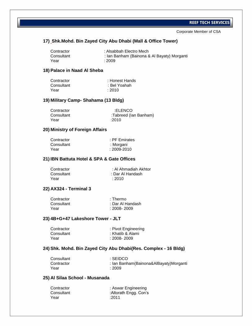
17) Shk.Mohd. Bin Zayed City Abu Dhabi (Mall & Office Tower)
Contractor : Alsabbah Electro Mech Consultant : Ian Banham (Bainona & Al Bayaty) Morganti Year : 2009
18) Palace in Naad Al Sheba
Contractor : Honest Hands Consultant : Bel Yoahah Year : 2010
19) Military Camp- Shahama (13 Bldg)
Contractor :ELENCO Consultant :Tabreed (Ian Banham) Year :2010
20) Ministry of Foreign Affairs Contractor : PF Emirates Consultant : Morgani Year : 2009-2010
21) IBN Battuta Hotel & SPA & Gate Offices
Contractor : Al Ahmadiah Akhtor Consultant : Dar Al Handash Year : 2010
22) AX324 - Terminal 3
Contractor : Thermo Consultant : Dar Al Handash Year : 2008- 2009
23) 4B+G+47 Lakeshore Tower - JLT
Contractor : Pivot Engineering Consultant : Khatib & Alami Year : 2008- 2009
24) Shk. Mohd. Bin Zayed City Abu Dhabi(Res. Complex - 16 Bldg)
Consultant : SEIDCO Contractor : Ian Banham(Bainona&AlBayaty)Morganti Year : 2009
25) Al Silaa School - Musanada
Contractor : Aswar Engineering Consultant :Altorath Engg. Con’s Year :2011
International Operations Business Group
Corporate Member of CSA
REEF TECH SERVICES
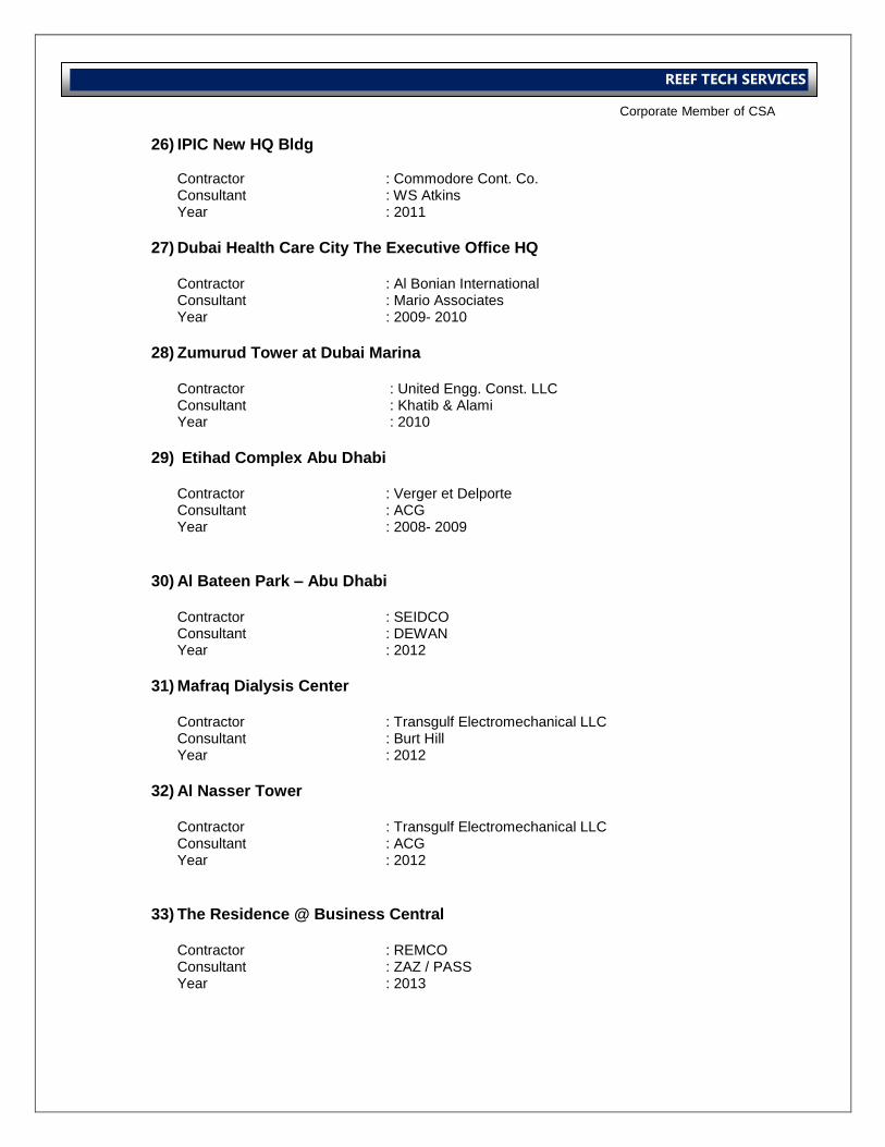
26) IPIC New HQ Bldg
Contractor : Commodore Cont. Co. Consultant : WS Atkins Year : 2011
27) Dubai Health Care City The Executive Office HQ
Contractor : Al Bonian International Consultant : Mario Associates Year : 2009- 2010
28) Zumurud Tower at Dubai Marina
Contractor : United Engg. Const. LLC Consultant : Khatib & Alami Year : 2010
29) Etihad Complex Abu Dhabi
Contractor : Verger et Delporte Consultant : ACG Year : 2008- 2009
30) Al Bateen Park – Abu Dhabi
Contractor : SEIDCO Consultant : DEWAN Year : 2012
31) Mafraq Dialysis Center
Contractor : Transgulf Electromechanical LLC Consultant : Burt Hill Year : 2012
32) Al Nasser Tower
Contractor : Transgulf Electromechanical LLC Consultant : ACG Year : 2012
33) The Residence @ Business Central
Contractor : REMCO Consultant : ZAZ / PASS Year : 2013
International Operations Business Group
Corporate Member of CSA
REEF TECH SERVICES
34) Burjside Boulevard @ Business Central
Contractor : REMCO Consultant : ZAZ / PASS Year : 2013
35) Dubai Waterfront – Veneto East
Contractor : ETTS Consultant : CHSS Year : 2013
36) Golf Garden II Project
Contractor : Pivot Engineering & Gen. Contracting Consultant : JLA Year : 2013
37) The Residence @ Business Central
Contractor : REMCO Consultant : ZAZ / PASS Year : 2013
International Operations Business Group
Corporate Member of CSA
REEF TECH SERVICES
International Operations Business Group
Corporate Member of CSA
REEF TECH SERVICES
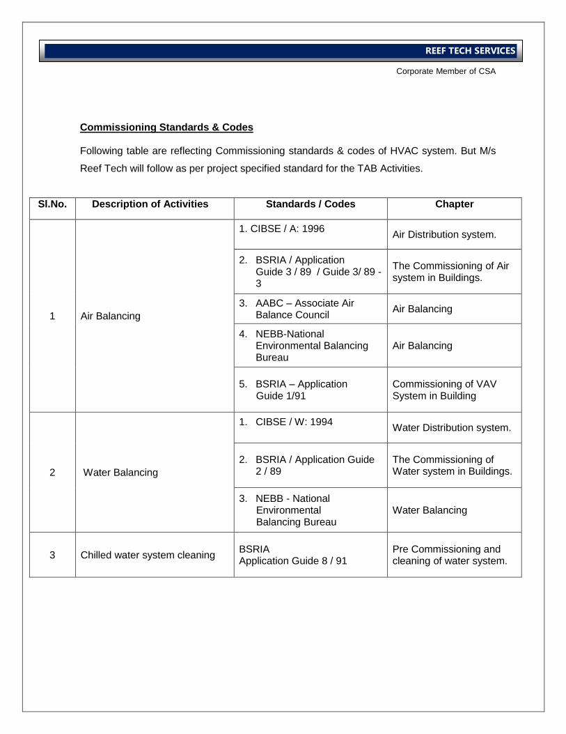
Commissioning Standards & Codes Following table are reflecting Commissioning standards & codes of HVAC system. But M/s
Reef Tech will follow as per project specified standard for the TAB Activities.
Sl.No. Description of Activities Standards / Codes Chapter
1 Air Balancing
1. CIBSE / A: 1996
Air Distribution system.
2. BSRIA / Application Guide 3 / 89 / Guide 3/ 89 - 3
The Commissioning of Air system in Buildings.
3. AABC – Associate Air Balance Council
Air Balancing
4. NEBB-National Environmental Balancing Bureau
Air Balancing
5. BSRIA – Application Guide 1/91
Commissioning of VAV System in Building
2 Water Balancing
1. CIBSE / W: 1994
Water Distribution system.
2. BSRIA / Application Guide 2 / 89
The Commissioning of Water system in Buildings.
3. NEBB - National Environmental Balancing Bureau
Water Balancing
3 Chilled water system cleaning BSRIA Application Guide 8 / 91
Pre Commissioning and cleaning of water system.
International Operations Business Group
Corporate Member of CSA
REEF TECH SERVICES
International Operations Business Group
Corporate Member of CSA
REEF TECH SERVICES
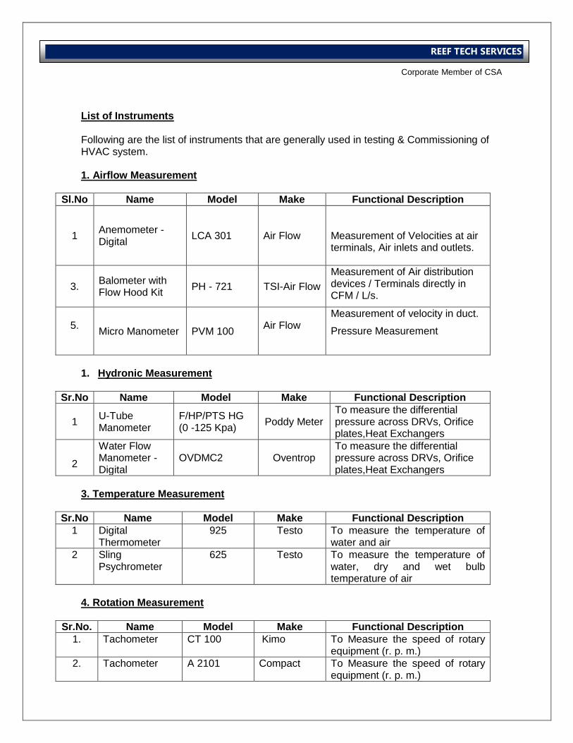
List of Instruments
Following are the list of instruments that are generally used in testing & Commissioning of HVAC system.
1. Airflow Measurement
Sl.No Name Model Make Functional Description
1 Anemometer - Digital
LCA 301
Air Flow
Measurement of Velocities at air terminals, Air inlets and outlets.
3. Balometer with Flow Hood Kit
PH - 721 TSI-Air Flow
Measurement of Air distribution devices / Terminals directly in CFM / L/s.
5.
Micro Manometer PVM 100 Air Flow
Measurement of velocity in duct.
Pressure Measurement
1. Hydronic Measurement
Sr.No Name Model Make Functional Description
1 U-Tube Manometer
F/HP/PTS HG (0 -125 Kpa)
Poddy Meter To measure the differential pressure across DRVs, Orifice plates,Heat Exchangers
2
Water Flow Manometer - Digital
OVDMC2 Oventrop To measure the differential pressure across DRVs, Orifice plates,Heat Exchangers
3. Temperature Measurement
Sr.No Name Model Make Functional Description
1 Digital Thermometer
925 Testo To measure the temperature of water and air
2 Sling Psychrometer
625 Testo To measure the temperature of water, dry and wet bulb temperature of air
4. Rotation Measurement
Sr.No. Name Model Make Functional Description
1. Tachometer CT 100 Kimo
To Measure the speed of rotary equipment (r. p. m.)
2. Tachometer A 2101 Compact
To Measure the speed of rotary equipment (r. p. m.)
International Operations Business Group
Corporate Member of CSA
REEF TECH SERVICES
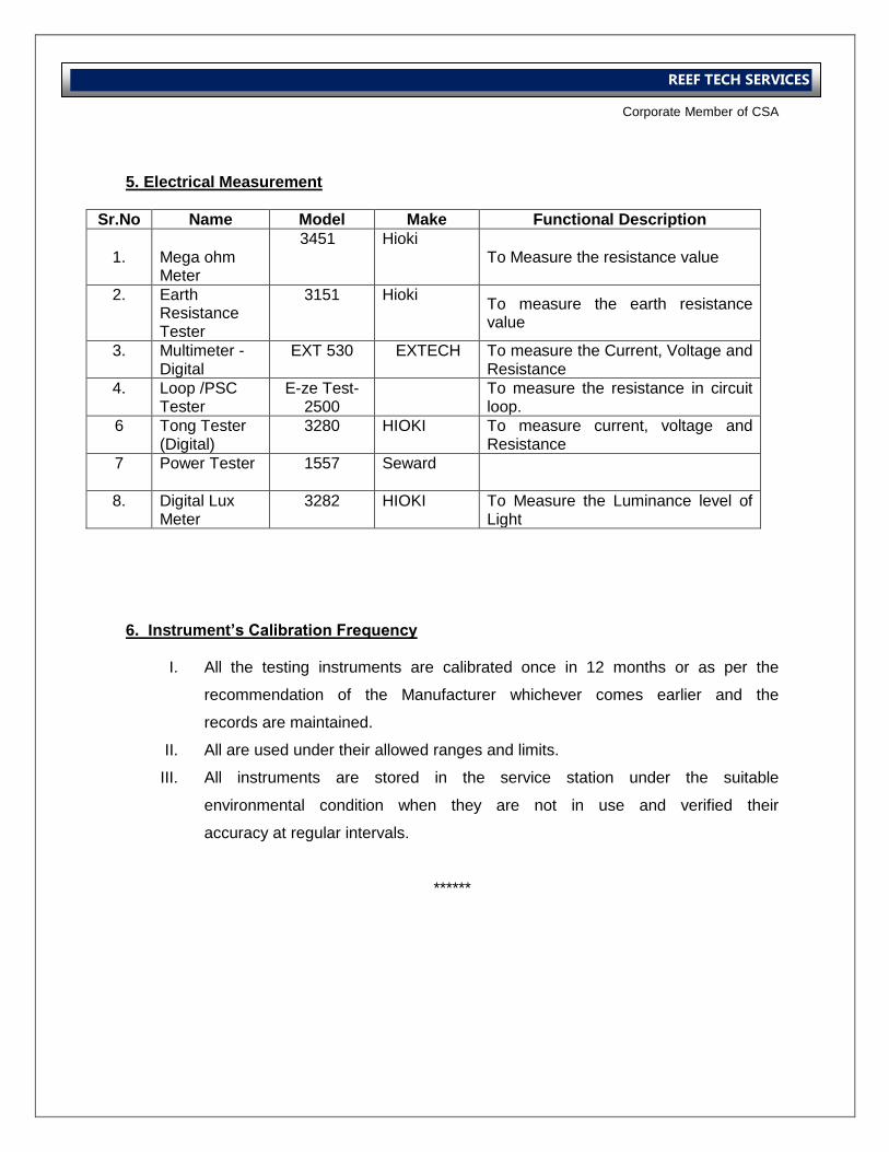
5. Electrical Measurement
Sr.No Name Model Make Functional Description
1.
Mega ohm Meter
3451 Hioki To Measure the resistance value
2.
Earth Resistance Tester
3151 Hioki To measure the earth resistance value
3. Multimeter - Digital
EXT 530 EXTECH To measure the Current, Voltage and Resistance
4. Loop /PSC Tester
E-ze Test-2500
To measure the resistance in circuit loop.
6 Tong Tester (Digital)
3280 HIOKI To measure current, voltage and Resistance
7 Power Tester 1557 Seward
8. Digital Lux Meter
3282 HIOKI To Measure the Luminance level of Light
6. Instrument’s Calibration Frequency
I. All the testing instruments are calibrated once in 12 months or as per the
recommendation of the Manufacturer whichever comes earlier and the
records are maintained.
II. All are used under their allowed ranges and limits.
III. All instruments are stored in the service station under the suitable
environmental condition when they are not in use and verified their
accuracy at regular intervals.
******

International Operations Business Group
Corporate Member of CSA
REEF TECH SERVICES
International Operations Business Group
Corporate Member of CSA
REEF TECH SERVICES
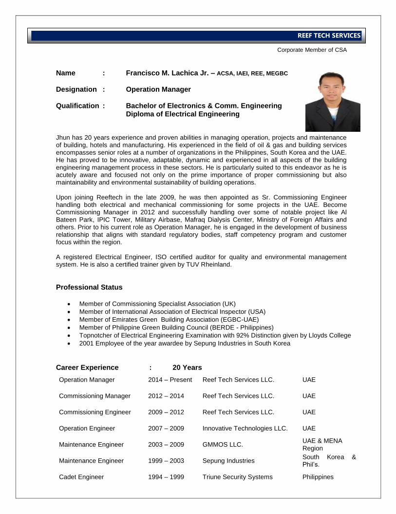
Name : Francisco M. Lachica Jr. – ACSA, IAEI, REE, MEGBC Designation : Operation Manager Qualification : Bachelor of Electronics & Comm. Engineering Diploma of Electrical Engineering Jhun has 20 years experience and proven abilities in managing operation, projects and maintenance of building, hotels and manufacturing. His experienced in the field of oil & gas and building services encompasses senior roles at a number of organizations in the Philippines, South Korea and the UAE. He has proved to be innovative, adaptable, dynamic and experienced in all aspects of the building engineering management process in these sectors. He is particularly suited to this endeavor as he is acutely aware and focused not only on the prime importance of proper commissioning but also maintainability and environmental sustainability of building operations. Upon joining Reeftech in the late 2009, he was then appointed as Sr. Commissioning Engineer handling both electrical and mechanical commissioning for some projects in the UAE. Become Commissioning Manager in 2012 and successfully handling over some of notable project like Al Bateen Park, IPIC Tower, Military Airbase, Mafraq Dialysis Center, Ministry of Foreign Affairs and others. Prior to his current role as Operation Manager, he is engaged in the development of business relationship that aligns with standard regulatory bodies, staff competency program and customer focus within the region. A registered Electrical Engineer, ISO certified auditor for quality and environmental management system. He is also a certified trainer given by TUV Rheinland.
Professional Status
Member of Commissioning Specialist Association (UK)
Member of International Association of Electrical Inspector (USA)
Member of Emirates Green Building Association (EGBC-UAE)
Member of Philippine Green Building Council (BERDE - Philippines)
Topnotcher of Electrical Engineering Examination with 92% Distinction given by Lloyds College
2001 Employee of the year awardee by Sepung Industries in South Korea
Career Experience : 20 Years
Operation Manager 2014 – Present Reef Tech Services LLC. UAE
Commissioning Manager 2012 – 2014 Reef Tech Services LLC. UAE
Commissioning Engineer 2009 – 2012 Reef Tech Services LLC. UAE
Operation Engineer 2007 – 2009 Innovative Technologies LLC. UAE
Maintenance Engineer 2003 – 2009 GMMOS LLC. UAE & MENA Region
Maintenance Engineer 1999 – 2003 Sepung Industries South Korea & Phil’s.
Cadet Engineer 1994 – 1999 Triune Security Systems Philippines
International Operations Business Group
Corporate Member of CSA
REEF TECH SERVICES
Operation Manager Reeftech Services LLC – Dubai Reeftech Electromechanical & Electrical Contracting LLC – Abu Dhabi Responsibilities:
Improve the operational systems, processes and policies in support of organizations mission -- specifically, support better management reporting, information flow and management, business process and organizational planning.
Manage and increase the effectiveness and efficiency of Support Services through improvements to each function as well as coordination and communication between support and business functions.
Play a significant role in long-term planning, including an initiative geared toward operational excellence.
Oversee overall Commissioning management, planning, systems and controls.
Management of organization manpower requirements in every project in coordination with the Managing Director.
Development of individual competency program specially for TAB works
Organization of fiscal documents.
Regular meetings with Managing Director around fiscal planning.
Supervise and check TAB manager requirements on a daily basis.
Responsibilities by Function Financial Management
Direct annual budgeting and planning process for the organization's annual budget with Managing Director
Develop and manage annual budget
Oversee monthly and quarterly assessments and forecasts of organization's financial performance against budget, financial and operational goals. Oversee short and long-term financial and managerial reporting.
Reconciling monthly activity, generating year-end reports, and fulfilling related requirements.
Assisting Managing Director and Board in creating annual organizational budget and monitoring cash flow.
Managing grantor contracts and reimbursement requests.
Maintaining Intersection's archival and administrative files.
Administering payroll and employee benefits and organizational insurance.
Ensure that Accounting Department requests are resolved and communicated in a timely manner to internal and external parties.
Develop long-range forecasts and maintain long-range financial plans.
Develop, maintain and monitor all fundraising and accounting systems and procedures capturing all pledges, billings and receipts and for the recording of all revenue transactions, recommend and implement improvements to systems.
Organizational Effectiveness
Manage functions and project requirements
Drive initiatives in the management team and organizationally that contribute to long-term operational excellence.
Providing consulting services on matters related to business structure and growth.
Contribute to short and long-term organizational planning and strategy as a member of the management team
International Operations Business Group
Corporate Member of CSA
REEF TECH SERVICES
Commissioning Manager – MEP Al Bateen Park Dev’t. Project Abu Dhabi, UAE
To take full control of the project and be responsible to the employer. Responsible on behalf of the employer to the client for all site events within the scope of the contract. Agree documentation requirements and standard. Evaluate labour requirements against the programme and tender submission. Skilled in communication and man-management, recognized strengths and weakness in those I delegate and work to form an effective team. Responsible to respond changes in requirements objectively, identify all design data and ensure adherence to specific standards. Produce commissioning reports to the satisfaction of employers and clients. Review and evaluate commissionability of design to minimize time taken on site, ensure client satisfaction with the end product and maximize company efficiency. Produce technical reports and hold discussions with designers to improve commissionability. Evaluate the technical aspects of method statements for specialists, understand and apply the requirements for correct instrumentation in checking and witnessing specialist’s work. Responsible for all aspects of site including risk assessment, method statements and tool box talks. Fully aware of company’s policies in respect of contractual
commitments. Responsible for achieving successful completion of the project. Commissioning Manager - HVAC IPIC Headquarters Abu Dhabi, UAE
Fully conversant with the structure of the project management. Liaised with the client’s representative and accept the instruction in accordance with the company procedures. Carry out commissionability review of all systems under my control, carryout witness testing of systems and operate company’s policy for completion certification. Liaise with other trades on site to ensure access is available as required for works. Write concise reports to accompany test documentation for record purposes. Produced method statements for work which control directly and to obtain, coordinate and submit, as necessary, method statements from specialist. Ensure correct procedures are followed for pre-commissioning and essential actions are taken. Monitor and record progress of commissioning and all other trades which directly or indirectly after commissioning. Undertake reviews of building services designs with respect design to commissionability. Fully understand drawings, specifications and contractual commitments for the project.
Commissioning Engineer – HVAC Al Muneera Island – Mainland Al Raha Development Abu Dhabi, UAE Review of specifications, drawing design details to ensure Commissioning ability of the system. Ensuring system readiness for commissioning, mobilization of technicians to allow continuity of works to comply with program deadlines. On site problem solving, attend site meeting with sub-contractors and main contractors, liaise with Consultants, compile test reports to the satisfaction of the client and ensure the commissioned project meets the designed requirements and acceptable to all parties. Allocate resources to carry out successful commissioning of the projects. Ensure, control and maintain the necessary standards in respect of test instruments. Ensure the requirements for pre-commissioning & commissioning are incorporated in the installation. Assist in producing a commissioning program. Produced a method of statement for each project. Ensure the calibration of all test instruments. Planning of daily works with commissioning and technician team. Liaise with installer and execute site measurements as per approved drawing & format. Attend as nominee for the company as witnessing. Prepare manpower, materials, tools and maintenance of test equipments. Preparation of documentation for field of work. Observe total safety issues in the site, conduct risk assessment before commencing for works.
International Operations Business Group
Corporate Member of CSA
REEF TECH SERVICES
Commissioning Engineer – HVAC / Electrical Mafraq Dialysis Center Abu Dhabi, United Arab Emirates Responsible for verification of all electrical installation, cable testing, inspection from cold to hot test and responsible for turn-over to the consultant. Responsibilities include the establishment of the QA and documentation system, creating inspection and test plans to ISO9002, organizing and scheduling of electrical teams to work within the time schedule, raising and handling of all testing queries, request for inspection (RFI’s), variation orders, additional work and free issue material, weekly progress reports, invoicing of monthly progress payments, document control and site administration. Duties also include overall responsibility for the implementation / upholding of strict safety codes and QA/QC procedure on site. Follow IEE regulation and electrical installations. Fully aware of company’s policies in respect of contractual commitments. Responsible of all aspects of site safety and others including risk assessment.
Testing Engineer – HVAC/Electrical Atlantis, The Palm Dubai, United Arab Emirates Checked the installation of new PICV for all 34 Heat Exchanger with a team of qualified Mechanical & Electrical engineers. Duties include wiring installation from the control valve to the smart card panel. Testing & commissioning phase includes continuity test of all shielded wire from BMS panel to the Smart Card Panel, Control Valve to the Pressure Sensor. Functional test of the system is monitored by the software installed in the tablets. Responsible for testing the termination of all cable to BMS panel.
Commissioning Engineer - Electrical Zumurod Tower Dubai, United Arab Emirates
Responsible for the commissioning of all Low and Medium Voltage Switchgear up to 33KV, Emergency Diesel Generators, Lighting & Small Power, Motor Controls Centre’s and Cabling System. With a team of 10 engineers working for my team to cover the jobs required in the tower, and train junior engineers on the correct use, functioning & testing of electrical testing equipment. Duties also include the selection and purchasing of new test equipment, and the scheduling / maintenance of a wide range of existing equipment, cost control of jobs, customer liaison, and engineering of design changes to electrical drawings.
Testing & Commissioning Engineer Notable Projects United Arab Emirates
Some projects and company contracts that I handle also are the following:
Energy Audit for American Hospital
Testing & Balancing of both Air & Water for Al Hamra 4 star Hotel in Deira Dubai
Water Verification by using Ultrasonic in various site in UAE like Shakespeare Restaurant in Dubai Mall, Mall of the Emirates, Park Rotana hotel pump room in Abu Dhabi, Jumeirah Beach Hotel, Flushing pipe line in Tabreed District Cooling in Jebel Ali Dubai, Branch line at 21st – 22nd Floor for Al Fattan Currency House, Gulf & Safa Diaries Pump Room, Burjuman Center Primary Supply, Sammach Fish Restaurant at Dubai Mall Souk.
Air & Water Balancing of Hard Rock Café at Festival City in Dubai.
Facility Maintenance Contract for Six Senses Resort in Oman
Water Balancing of Rosary School in Sharjah UAE.
International Operations Business Group
Corporate Member of CSA
REEF TECH SERVICES
Duct Leak Testing as per DW-144 in various project like Mafraq Dialysis Center, Fujeirah City Center, Habshan 5 Process Building (GASCO), Deep Panuke Oil Rig Living Quarter (MOPU) under AMB/SBM, Gulf News at DIP, Talisman Energy Oil Rig (MOPU) under AMB/SBM, Al Ain Ambulatory Clinic under Mercury Int’l., Etihad Tower under Commodore Contracting, ADIB Headquarters under Mercury
Electrical Investigation & Analysis for MAI Tower lighting problem under TEAM Engineering.
Water Balancing for Marinascape Tower retail services under Trident Consultancy.
Chiller and Water Balancing for Villa Rotana Suites & Apartments at Sheik Zayed Road.
Electrical Testing for 21st & 22nd floors of Financial Tower in Zheik Zyed Road under Paramount Contracting.
Testing Engineer EPC Electrical & Instrumentation Project United Arab Emirates Nov. – Dec. 2004 – Batam, Indonesia
Rebuilt, Tested and commissioned switchboards and MCC are which were extensively damaged in shipping.
March – May 2005 – Dubai Petroleum Testing and Commissioning of Air Breathing Apparatus, Diesel Compressors and Navigational Lighting System of Oil & Gas Platform at living quarters.
July – Dec. 2005 – Occidental Mukhaizna LLC
Installation, Testing & commissioning of all electrical & instrumentation equipments for Lomond Gas Platform was undertaken after earlier onshore pre-commissioning.
March – Sept. 2006 – Vietsovpetro
Supervision of Installation during the Electrical hook-up of 2 Water Injection Modules to the main platforms in the white tiger field. The subsequent testing and commissioning required extensive involvement with the DCS interfacing and Process Control Systems to successfully complete the project.
Nov. – Dec. 2006 – Margham Dubai Est.
Margham extensive expansion of their turbine electrical modifications preceded the testing and commissioning of Switchgear, Motor Control Centre’s, Lighting and Small Power. Supervise our own testing crews; customers training were all conducted inside a tight schedule.
Feb. – July 2007 – Lamprell Dubai
After modification work the switchboards for the Iranian Offshore Oil Co.’s Salman Project Oil & Gas Platforms were pre-commissioned onshore in dry dock. Commissioning of the Platforms in the Persian Gulf required extended periods offshore to meet the schedule.
Sept. – Dec 2007 – MOPU Talisman Energy
Contract for EPC project to do the E & I from installation to testing & commissioning. Testing & commissioning of all cables, equipments and functional test for the Submersible Rig Controls.
March 2008 – Oct. 2009 – TDS2000 Rig 1 & 2, TDS 2500 Oil Rig , SBM Offshore
Working in close co-operation with the site contractor, our contract is from installation to testing & commissioning of 3 Oil Rig Project with respect to E & I project. Responsibility includes working with the QA/QC for site testing of equipment, cable testing as per cable schedule.
International Operations Business Group
Corporate Member of CSA
REEF TECH SERVICES
SEMINARS / TRAINING ATTENDED
Energy Management May 06,2003 ( Dir. Aniano Matabuena Jr., CEZIA )
Training the Trainors and Evaluation for Training Effectiveness June 30, 2002, July 1-4 and 10, 2002 (RRS Management System)
ISO 9001:2000 version Internal / External Auditing Course June 18-19, 24-25, 2002 (RRS Management System)
Low Voltage Splicing Method April 23, 2002 (3M Electrical Division)
New Generation of Motor Protection and High Tech Solution for Motor Controls February 01, 2002 (Schneider Electric
Documentation and Record Management January 15-16, 2002 (RRS Management System)
ISO 9001:2000 Version Introductory Course January 09-10, 2002 (RRS Management System)
Loss Control Seminar December 13, 2001 ( Engr. Cuba, PSSE Director )
Motor Control Protection and Components Training July 13, 2001 (Schneider Electric)
Principle and Application of Miniature Circuit Breaker for Industrial Applications and Coordination of Motor Protection March 16, 2001 (Schneider Electric)
EMS 14001 Internal / External Auditing Course March 22-25, 2000 (TUV Rheinland)
Training Needs Analysis February 02, 04, 08 2000 (TUV Rheinland)
EMS 14001 Introductory Course February 17-18, 2000 (TUV Rheinland)
Safety Awareness Training Feb. 12, 2006 (GMMOS, Dubai)
Basic Fire Fighting Course July 04, 2007 (GMMOS, Dubai)
ESTIDAMA Introduction March 2012 (Ministry of Urban Planning, Abu Dhabi)
LEED Green Associate January 2014 (Chicago Institute, Abu Dhabi)
International Operations Business Group
Corporate Member of CSA
REEF TECH SERVICES
Name : Mr. Clark Jayson Baron – ACSA Grade 3
Designation : Commissioning Manager
Qualification : Bachelor of Mechanical Engineering Jayson is a highly motivated engineer and self directed, with initiative to evaluate and solve problems in the project. His contribution of commissioning, retro-commissioning, energy efficiency retrofits and demand response project proves that he is capable for handling big scale projects. He provide leadership in the dynamic field of energy and sustainability projects and services tailored to diverse client base while maintaining the highest level of integrity and innovation. He is directly monitoring the commissioning plan, site programs, field reports for construction projects and assist customers through the implementation. Jayson is currently holding the position of Commissioning Manager handling various projects in Dubai and Abu Dhabi. He successfully hand over numerous project from Damac, Nakheel, Aldar and Fibrex. He graduated a degree of Mechanical Engineering from Mapua Institute of Technology – Philippines; and a member of Commissioning Specialist Association (UK) Grade 3.
Career Experience : 10 Years
Commissioning Manager 2014 - Present Reeftech Services LLC. UAE
Sr. Commissioning Engineer 2011 - 2014 Reeftech Services LLC. UAE
Commissioning Engineer 2010 - 2011 Lead Electromechanical UAE
Commissioning Supervisor 2007 - 2010 Reeftech Services LLC. UAE
Mechanical Engineer 2006 - 2007 Bin Bilaila Baytur Cont. Co. UAE
Auto Cad Engineer 2005 - 2006 RKG Metal Fabrication Philippines
Commissioning Manager Reeftech Services LLC – Dubai Reeftech Electromechanical & Electrical Contracting LLC – Abu Dhabi Responsibilities:
To be responsible for all aspects of site safety, including risk assessment, method statement and tool box talks.
To take full control of one or more projects and be responsible in the organization
To fully understand drawings, specifications and contractual commitments for the project.
To be responsible, on behalf of the employer to the client for all site events within the scope of the contract
To agree documentation requirements and standards
International Operations Business Group
Corporate Member of CSA
REEF TECH SERVICES
To be fully aware of company’s policies in respect of contractual commitments.
To evaluate labour requirements against the program and submissions
To produce programs, using proprietary software, coordinated with the main construction program, to aid timely completion of the contract.
To ensure the correct procedures are followed and recorded for pre-commissioning and any necessary actions are taken.
To monitor and record progress of commissioning and all other trades which directly or indirectly affect commissioning.
To be skilled in communication and man-management
To have a working knowledge of all specialized activities associated with any discipline.
To recognize strengths and weaknesses in those to who delegate and work to form an effective team.
To respond to changes in requirements objectively.
To identify all design data and ensure adherence to specific standards.
To recognize own abilities and know when to call for assistance in dealing with matters which fall beyond experience
To produce commissioning reports to the satisfaction of employer and clients
To review and evaluate commissionability of designs to minimize time taken on site, ensure client satisfaction with the end product and maximize company efficiency
To report regularly and as required to the employer on all aspects of the work. Projects Completed
Capital Bay (DAMAC 3) – Dubai, UAE
Military Works–CMW–11098–C001, Camp ID 613201 – RAK, UAE
Badrah Development – AREEJ District Stage 1 – Dubai,UAE
Deerfields Townsquare – Abu Dhabi, UAE
Residential Building @ Dubai Land – Dubai, UAE
The Burj Side Boulevard Tower (DAMAC 1) – Dubai, UAE
The Residences (DAMAC 2) @ Business Central – Dubai, UAE
Ambulatory Health Care Center – Al Ain, UAE
Maleha Military Camp – Sharjah, UAE
IPIC Headquarters – Abu Dhabi, UAE
Sheik Khalifa Medical Center Extension – Abu Dhabi, UAE
Al Bateen Park Development – Abu Dhabi, UAE
BMC Mall (Capital Mall) – Abu Dhabi, UAE
The Mall – Al Ain, UAE
Al Raha Beach Resort & Residence – Abu Dhabi, UAE
Nasr Tower - Abu Dhabi, UAE
ADNOC Accommodation – Ruwais, Abu Dhabi, UAE
Salem Tower – Sharjah, UAE
Ritaj Residence – Dubai, UAE – Lead Electromechanical
International Operations Business Group
Corporate Member of CSA
REEF TECH SERVICES
G+11 Residential Building – Dubai, UAE
G+9 Storey Residential Building – Dubai, UAE
Dubai International Airport Extension (Terminal 3) – Dubai, UAE
Ruwais Housing Complex Bachelor Flats Phase III – Abu Dhabi, UAE
Miramar Hotel – Fujairah, UAE
Sheikh Ahmed Al Hamed Residential Buildings – Dubai, UAE
Commercial / Residential Buildings Plot E2 (Jumeirah Lake Towers) – Dubai, UAE
Commercial and Residential Development (Jumeirah Mall) – Dubai, UAE
Lakeshore Tower – 1 – Dubai, UAE
Ghobash Tower Plot no - C -31 – Abu Dhabi, UAE
Proposed Addition of G+3 Building to existing AMERICAN COLLEGE – Dubai, UAE
Development of Plot C-1/Z-9 Shk. Mohammed Bin Zayed City – Abu Dhabi, UAE
Dubai Health Care City (DHCC) – Dubai, UAE
New Laboratories Building & New ITD Building @ D.C.L. – Dubai, UAE
Zumurud Tower – Dubai, UAE
Ministry of Foreign Affairs - Abu Dhabi, UAE
Yas Island Development (Ferrari Experience) - Abu Dhabi, UAE
Silver Wave Tower – Abu Dhabi, U.A.E.
Building for Mr. Sultan Ghanoum Al Hamelye – 11 C-24, Abu Dhabi, U.A.E.
U.A.E. University, Al Ain, Abu Dhabi, U.A.E.
IBN Batuta Hotel & Spa and Gate Offices – Dubai, U.A.E.
International Operations Business Group
Corporate Member of CSA
REEF TECH SERVICES
Name : Mr. Sreekumar C.T. – ACSA Grade 3
Designation : Sr. Commissioning Supervisor
Qualification : Diploma of RAC Engineering Sreekumar is one of the pioneer member in the organization. He is one of the core back bone of Reeftech during that time when it was started. He is well skilled in maintaining detailed and accurate project records including data, documentation and progress report. He has dedication in completing projects on time and within a budget. His technical skills in Testing and Commissioning put him into senior role for our previous project in ADNOC, SOROUH, and DAMAC etc. Having a Diploma of Refrigeration and Air-Conditioning, Sreekumar is a hands on engineer having a Grade 3 certificate from the Commissioning Specialist Association (UK).
Career Experience : 20 Years
Sr. Commissioning Supervisor 2014 - Present Reeftch Services LLC. UAE
Commissioning Supervisor 2012 - 2014 Reeftch Services LLC. UAE
Sr. HVAC TAB Technician 2006 - 20010 Reeftch Services LLC. UAE
HVAC TAB Technician 2005 - 2006 Seder Group UAE
HVAC TAB Technician 1999 - 2005 Transgulf Electromechanical LLC.
UAE
Air Condition Technician 1996 - 1999 Trimurthi Air Control Services INDIA
Air Condition Technician 1993 - 1996 Voltas Ltd INDIA
Sr. Commissioning Supervisor Reeftech Services LLC – Dubai Reeftech Electromechanical & Electrical Contracting LLC – Abu Dhabi Responsibilities:
To be responsible for all aspects of site safety, including risk assessment, method statement and tool box talks.
To be skilled in communication and man management
To fully understand drawings, specifications and contractual commitments for the project.
To produce method statements for work which control directly and to obtain, coordinate and submit as necessary from specialists.
To obtain approval for method statements submitted.
To be fully aware of company’s policies in respect of contractual commitments.
International Operations Business Group
Corporate Member of CSA
REEF TECH SERVICES
To liaise with client’s representative on all matters concerning the project.
To produce programs, using proprietary software, coordinated with the main construction program, to aid timely completion of the contract.
To ensure the correct procedures are followed and recorded for pre-commissioning and any necessary actions are taken.
To monitor and record progress of commissioning and all other trades which directly or indirectly affect commissioning.
To be skilled in detailed report writing, planning and site meetings.
To have a working knowledge of all specialized activities associated with any discipline.
To undertake reviews of building services designs with respect to commission ability and obtain approval of the same.
To understand and apply the requirements for correct instrumentation in checking and witnessing specialist work.
To identify all design data and ensure adherence to specific standards.
To report regularly and as required to the employer on all aspects of the work. Projects Completed
Dubai Waterfront - Badrah
Dubai Waterfront - Veneto
CMW Mahwi Camp
Sheik Kalifa Medical Center – Abu Dhabi
Military Air Base - RAK
Abraj District Cooling – Abu Dhabi
Maliha Military Camp - Sharjah
Habshan 5 Granulation Plant
Dubai Waterfront Villas
Golf Gardens – Abu Dhabi
G+19 Damac 5
Ruwais Housing Complex Package 11A
Extension of Exhibition Halls (Dubai World Trade Centre), Dubai
Al Tawam Hospital, Al Ain
Discovery Gardens, Dubai
Jumeirah Beach Residence – Sector 2 – Bldg. 3.1, 3.2 & Podium, Dubai
Burj Dubai - Old Town Commercial Island, Dubai
Dubai Airport Exec. Hanger, Dubai
G + 20 Commercial Building – (20 Floors), Abu Dhabi
Wafi Mall & Hotel Extension, Dubai
Department of Health – Health Centres, Abu Dhabi
Villas @ Al Barrari Development - Phase 1, Dubai
Ministry of Foreign Affairs, Abu Dhabi
Madinat Jumeirah
International Operations Business Group
Corporate Member of CSA
REEF TECH SERVICES
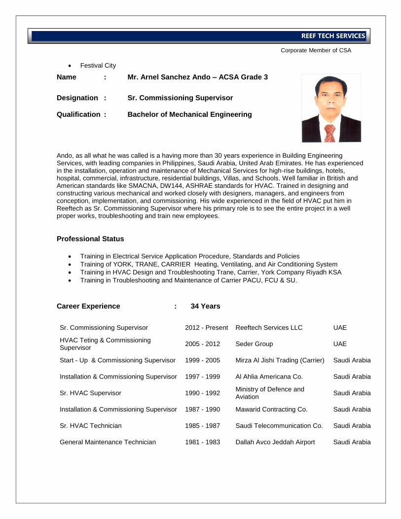
Festival City
Name : Mr. Arnel Sanchez Ando – ACSA Grade 3
Designation : Sr. Commissioning Supervisor
Qualification : Bachelor of Mechanical Engineering Ando, as all what he was called is a having more than 30 years experience in Building Engineering Services, with leading companies in Philippines, Saudi Arabia, United Arab Emirates. He has experienced in the installation, operation and maintenance of Mechanical Services for high-rise buildings, hotels, hospital, commercial, infrastructure, residential buildings, Villas, and Schools. Well familiar in British and American standards like SMACNA, DW144, ASHRAE standards for HVAC. Trained in designing and constructing various mechanical and worked closely with designers, managers, and engineers from conception, implementation, and commissioning. His wide experienced in the field of HVAC put him in Reeftech as Sr. Commissioning Supervisor where his primary role is to see the entire project in a well proper works, troubleshooting and train new employees.
Professional Status
Training in Electrical Service Application Procedure, Standards and Policies
Training of YORK, TRANE, CARRIER Heating, Ventilating, and Air Conditioning System
Training in HVAC Design and Troubleshooting Trane, Carrier, York Company Riyadh KSA
Training in Troubleshooting and Maintenance of Carrier PACU, FCU & SU.
Career Experience : 34 Years
Sr. Commissioning Supervisor 2012 - Present Reeftech Services LLC UAE
HVAC Teting & Commissioning Supervisor
2005 - 2012 Seder Group UAE
Start - Up & Commissioning Supervisor 1999 - 2005 Mirza Al Jishi Trading (Carrier) Saudi Arabia
Installation & Commissioning Supervisor 1997 - 1999 Al Ahlia Americana Co. Saudi Arabia
Sr. HVAC Supervisor 1990 - 1992 Ministry of Defence and Aviation
Saudi Arabia
Installation & Commissioning Supervisor 1987 - 1990 Mawarid Contracting Co. Saudi Arabia
Sr. HVAC Technician 1985 - 1987 Saudi Telecommunication Co. Saudi Arabia
General Maintenance Technician 1981 - 1983 Dallah Avco Jeddah Airport Saudi Arabia
International Operations Business Group
Corporate Member of CSA
REEF TECH SERVICES
Sr. Commissioning Supervisor Reeftech Services LLC – Dubai Reeftech Electromechanical & Electrical Contracting LLC – Abu Dhabi Responsibilities:
To be responsible for all aspects of site safety, including risk assessment, method statement and tool box talks.
To be skilled in communication and man management
To fully understand drawings, specifications and contractual commitments for the project.
To produce method statements for work which control directly and to obtain, coordinate and submit as necessary from specialists.
To obtain approval for method statements submitted.
To be fully aware of company’s policies in respect of contractual commitments.
To liaise with client’s representative on all matters concerning the project.
To produce programs, using proprietary software, coordinated with the main construction program, to aid timely completion of the contract.
To ensure the correct procedures are followed and recorded for pre-commissioning and any necessary actions are taken.
To monitor and record progress of commissioning and all other trades which directly or indirectly affect commissioning.
To be skilled in detailed report writing, planning and site meetings.
To have a working knowledge of all specialized activities associated with any discipline.
To undertake reviews of building services designs with respect to commission ability and obtain approval of the same.
To understand and apply the requirements for correct instrumentation in checking and witnessing specialist work.
To identify all design data and ensure adherence to specific standards.
To report regularly and as required to the employer on all aspects of the work.
Projects Completed
Military Airbase – Abu Dhabi
Jumeirah Beach Residence #3 Project. Dubai
Dubai Health Care…Saudi Hospital.Dubai
Boston Universsity Hospital, Health Care Dubai
Wafi City.Dubai
Dubai Waterfront – Venet0
Wafi Housing and Accomodation Block A- H…Zonah 4 .Dubai
Dubai International Financing Center, Dubai
Dubai Festival City., Harbor Plaza, Dubai
Mirdif Al-Nakheel Project Bldg 1to 32.,Apartment backside of Carrefour.Dubai
Ritz Carlton Hotel .DIFC area,Dubai
Dubai Metro Rashadiya,Main Depo Red Line.Dubai
Dubai Metro Jebel Ali, Red Line Dubai
International Operations Business Group
Corporate Member of CSA
REEF TECH SERVICES
Dubai Metro Al Qusais, Green Line Dubai
E Max Hotel. Bhar Dubai
Monte Carlo Hotel Saadiyath Abu Dhabi
Dewa Fujeirah Water Plant, Fujeirah UAE
Al Nahda Bldg. Al Nahda Dubai
Cultural Heritage Bldg. Abu Dhabi
J1 Jumeirah Lake Towers, Dubai
V3 Jumeirah lake Towers, Dubai
Holiday Inn Express Hotel, Knowledge Village. Dubai
Al Tayar Motor, Mushafa Abu Dhabi
CareFour Mirdif Center, Mirdif Dubai
Rolex Tower , Sheik Zayed, Dubai
International Operations Business Group
Corporate Member of CSA
REEF TECH SERVICES
Name : Mr. Nideesh Robert – SCSA Grade 2
Designation : Commissioning Engineer – HVAC / Electrical
Qualification : Bachelor of Electrical Engineering Career Experience : 5 Years
Commissioning Engineer 2012 - Present Reeftech Services LLC. UAE
Testing Engineer 2009 - 2012 Hi- Power Engineers & Consultant
INDIA
Jr. Commissioning Engineer Reeftech Services LLC – Dubai Reeftech Electromechanical & Electrical Contracting LLC – Abu Dhabi Responsibilities: HVAC
To be responsible for all aspects of site safety, including risk assessment, method statement and tool box talks.
To be skilled in communication and man management
To fully understand drawings, specifications and contractual commitments for the project.
To produce method statements for work which control directly and to obtain, coordinate and submit as necessary from specialists.
To obtain approval for method statements submitted.
To be fully aware of company’s policies in respect of contractual commitments.
To liaise with client’s representative on all matters concerning the project.
To produce programs, using proprietary software, coordinated with the main construction program, to aid timely completion of the contract.
To ensure the correct procedures are followed and recorded for pre-commissioning and any necessary actions are taken.
To monitor and record progress of commissioning and all other trades which directly or indirectly affect commissioning.
To be skilled in detailed report writing, planning and site meetings.
To have a working knowledge of all specialized activities associated with any discipline.
To undertake reviews of building services designs with respect to commission ability and obtain approval of the same.
To understand and apply the requirements for correct instrumentation in checking and witnessing specialist work.
To identify all design data and ensure adherence to specific standards.
To report regularly and as required to the employer on all aspects of the work.
International Operations Business Group
Corporate Member of CSA
REEF TECH SERVICES
ELECTRICAL
Interpret the design intent & manage the process of developing workshop drawings.
Submit specification complaint materials/Equipments for Consultant / client approval.
Prepare method statements for various construction activities.
Monitor progress of work with the aid of project construction programme & provide updates to
the project manager/construction manager.
Attend weekly progress meeting.
Testing and commissioning of up to 33kv indoor substation.
Commissioning of CT, PT, and all type of Circuit Breaker, Isolators and Lighting arrestor.
Commissioning of Indoor MDB,SMDB, ACDB, MLDB, ELDB & DCDB Panels
Scheme checking and problem analyzing of all control Electrical wiring circuits.
Conducting Hi-pot test for power cable & Bus bar.
Commissioning of Electromagnetic and Numerical Relays.
Preparation and implementation of Equipment testing procedures and test report Format.
Fire Fighting System Panel Scheme Check & Commissioning
Testing of Primary Injection and Secondary Injection of all type of switch Gears.
Commissioning of all Bus bar Protection, Sensitivity, Stability and Scheme checks
Commissioning of VFD Drives.
Liaising closely with other professionals, including structural engineers, builders, architects
and in-house project teams.
Identify & notify Quantity surveyors or project manager (As applicable) of any works which is
variation to originals cope of work.
Liaise with the commissioning team to facilitate commissioning of plants/ systems
Projects Completed
Dubai Waterfront - Veneto
Habshan 5 Granulation Plant
Borouge 3 Non – Process Building
Abu Dhabi Islamic Bank – Abu Dhabi
Passenger Building - AUH Airport Terminal 3
Screen Transfer Building – AUH Terminal 3
Deerfields Square Mall
G+6 Residential Building – DIP Dubai
Ruwais Housing Complex
International Operations Business Group
Corporate Member of CSA
REEF TECH SERVICES
Name : Mr. Nelvik Ando – ACSA Grade 3 Designation : TAB Engineer
Qualification : Degree in Mechanical Engineering
Career Experience : 10 Years
TAB Engineer 2013 - Present Reeftech Services LLC. UAE
TAB Engineer 2008 - 2013 Seder Group UAE
A/C Engineer 2005 - 2008 Samsung Corporation PHILIPPINES
A/C Technician 2003 - 2005 Pepsi Cola Corporation PHILIPPINES
Commissioning Supervisor Reeftech Services LLC – Dubai Reeftech Electromechanical & Electrical Contracting LLC – Abu Dhabi Responsibilities:
To be responsible for all aspects of site safety, including risk assessment, method statement and tool box talks.
To be skilled in communication and man management
To fully understand drawings, specifications and contractual commitments for the project.
To produce method statements for work which control directly and to obtain, coordinate and submit as necessary from specialists.
To obtain approval for method statements submitted.
To be fully aware of company’s policies in respect of contractual commitments.
To liaise with client’s representative on all matters concerning the project.
To produce programs, using proprietary software, coordinated with the main construction program, to aid timely completion of the contract.
To ensure the correct procedures are followed and recorded for pre-commissioning and any necessary actions are taken.
To monitor and record progress of commissioning and all other trades which directly or indirectly affect commissioning.
To be skilled in detailed report writing, planning and site meetings.
To have a working knowledge of all specialized activities associated with any discipline.
To undertake reviews of building services designs with respect to commission ability and obtain approval of the same.
To understand and apply the requirements for correct instrumentation in checking and witnessing specialist work.
To identify all design data and ensure adherence to specific standards.
To report regularly and as required to the employer on all aspects of the work.
International Operations Business Group
Corporate Member of CSA
REEF TECH SERVICES
Projects Completed
Dubai Metro Al Qusais, Green Line Dubai
E Max Hotel. Bhar Dubai
Monte Carlo Hotel Saadiyath Abu Dhabi
Dewa Fujeirah Water Plant, Fujeirah UAE
Al Nahda Bldg. Al Nahda Dubai
Cultural Heritage Bldg. Abu Dhabi
J1 Jumeirah Lake Towers, Dubai
V3 Jumeirah lake Towers, Dubai
Holiday Inn Express Hotel, Knowledge Village. Dubai
Al Tayar Motor, Mushafa Abu Dhabi
CareFour Mirdif Center, Mirdif Dubai
Rolex Tower , Sheik Zayed, Dubai
Salem Abdulla Tower – sharjah
IPIC- Abudhabi
Al Bateen Park Development – Abudhabi
Golf Gardens – Abudhabi
Al Raha Beach Development – Abudhabi
BMC Mall – Abudhabi
SKMC – Abudhabi
Burj Residence
Burj Boulevard
International Operations Business Group
Corporate Member of CSA
REEF TECH SERVICES
Name : Mr. Sygin Lawrence
Designation : Commissioning Supervisor
Qualification : Diploma in Electronics Career Experience : 16 Years
Commissioning Supervisor 2001 - Present Reef Tech Services LLC. UAE
Service Supervisor 2009 - 2001 Technoflow Trading UAE
Supervisor 2006 - 2009 Ostrich General Maintenance UAE
Sr. Technician 2003 - 2006 AA Environmental UAE
Sr. Technician 2000 - 2003 Al Estiqla Real Estate UAE
Technician 1998 - 2000 Al Boosi Electromechanical UAE
Commissioning Supervisor Reeftech Services LLC – Dubai Reeftech Electromechanical & Electrical Contracting LLC – Abu Dhabi Responsibilities:
To be responsible for all aspects of site safety, including risk assessment, method statement and tool box talks.
To be skilled in communication and man management
To fully understand drawings, specifications and contractual commitments for the project.
To produce method statements for work which control directly and to obtain, coordinate and submit as necessary from specialists.
To obtain approval for method statements submitted.
To be fully aware of company’s policies in respect of contractual commitments.
To liaise with client’s representative on all matters concerning the project.
To produce programs, using proprietary software, coordinated with the main construction program, to aid timely completion of the contract.
To ensure the correct procedures are followed and recorded for pre-commissioning and any necessary actions are taken.
To monitor and record progress of commissioning and all other trades which directly or indirectly affect commissioning.
To be skilled in detailed report writing, planning and site meetings.
To have a working knowledge of all specialized activities associated with any discipline.
To undertake reviews of building services designs with respect to commission ability and obtain approval of the same.
To understand and apply the requirements for correct instrumentation in checking and witnessing specialist work.
To identify all design data and ensure adherence to specific standards.
To report regularly and as required to the employer on all aspects of the work.
International Operations Business Group
Corporate Member of CSA
REEF TECH SERVICES
Projects Completed
Salem Abdulla Tower - sharjah
Masco - Dubai
IPIC- Abudhabi
Al Bateen Park Development - Abudhabi
Golf Gardens - Abudhabi
Al Raha Beach Development - Abudhabi
BMC Mall - Abudhabi
SKMC - Abudhabi
Jumeirah Beach Residence – Sector 2 – Bldg. 3.1, 3.2 & Podium, Dubai
Burj Dubai - Old Town Commercial Island, Dubai
Dubai Airport Exec. Hanger, Dubai
G + 20 Commercial Building – (20 Floors), Abu Dhabi
Wafi Mall & Hotel Extension, Dubai
Department of Health – Health Centres, Abu Dhabi
International Operations Business Group
Corporate Member of CSA
REEF TECH SERVICES
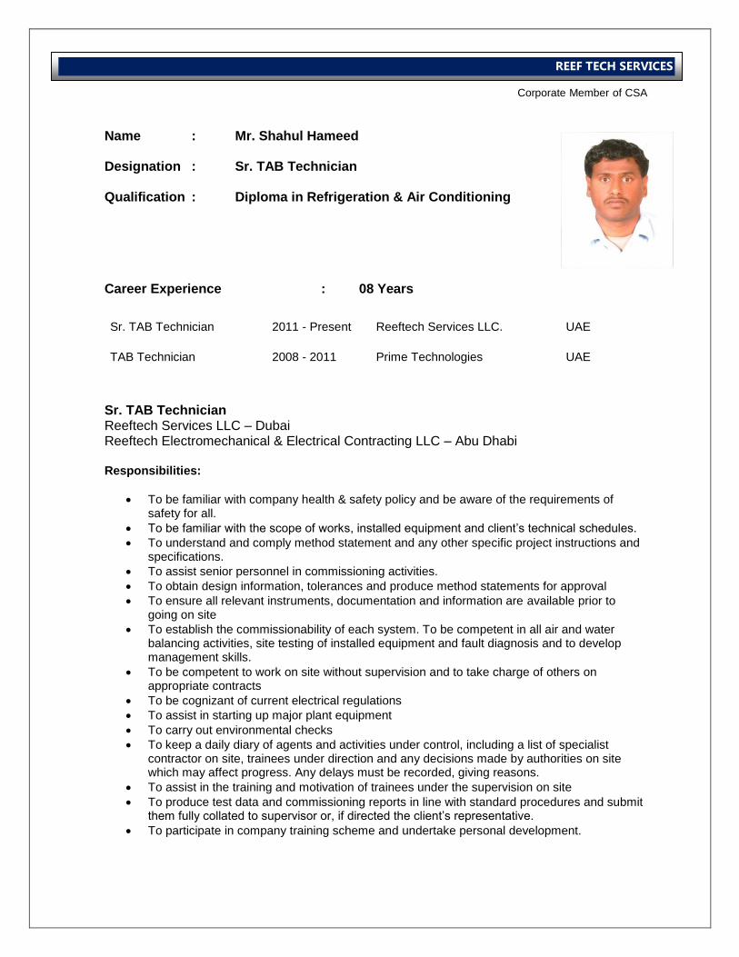
Name : Mr. Shahul Hameed
Designation : Sr. TAB Technician
Qualification : Diploma in Refrigeration & Air Conditioning Career Experience : 08 Years
Sr. TAB Technician 2011 - Present Reeftech Services LLC. UAE
TAB Technician 2008 - 2011 Prime Technologies UAE
Sr. TAB Technician Reeftech Services LLC – Dubai Reeftech Electromechanical & Electrical Contracting LLC – Abu Dhabi Responsibilities:
To be familiar with company health & safety policy and be aware of the requirements of safety for all.
To be familiar with the scope of works, installed equipment and client’s technical schedules.
To understand and comply method statement and any other specific project instructions and specifications.
To assist senior personnel in commissioning activities.
To obtain design information, tolerances and produce method statements for approval
To ensure all relevant instruments, documentation and information are available prior to going on site
To establish the commissionability of each system. To be competent in all air and water balancing activities, site testing of installed equipment and fault diagnosis and to develop management skills.
To be competent to work on site without supervision and to take charge of others on appropriate contracts
To be cognizant of current electrical regulations
To assist in starting up major plant equipment
To carry out environmental checks
To keep a daily diary of agents and activities under control, including a list of specialist contractor on site, trainees under direction and any decisions made by authorities on site which may affect progress. Any delays must be recorded, giving reasons.
To assist in the training and motivation of trainees under the supervision on site
To produce test data and commissioning reports in line with standard procedures and submit them fully collated to supervisor or, if directed the client’s representative.
To participate in company training scheme and undertake personal development.
International Operations Business Group
Corporate Member of CSA
REEF TECH SERVICES
Projects Completed
Salem Abdulla Tower – Sharjah
Dubai Metro Station (RTA)
Dubai Logistic City (DLC) Jebel Ali Airport Site.
STS Abudhabi
Master Institute ,AbuDhabi.
Al Bateen Park Development – Abudhabi
Golf Gardens – Abudhabi
Al Raha Beach Development – Abudhabi
BMC Mall – Abudhabi
SKMC – Abudhabi
IPIC- Abudhabi
Jumeirah Beach Residence, Dubai
Military Airbase – Abu Dhabi
Ministry of Foreign Affairs – Abu Dhabi
Ruwais Housing Complex
Damac Burj Boulevard
G+6 DIP Residential Building
Al Nasser Tower
Deerfields Square Mall
Passenger Building AUH Terminal 3
Dubai Waterfront – Veneto
International Operations Business Group
Corporate Member of CSA
REEF TECH SERVICES
Name : Mr. Upendra Deokar – ACSA Grade 3
Designation : Sr. TAB Technician
Qualification : Diploma in Electrical Career Experience : 12 Years
Sr. TAB Technician 2007 - Present Reeftech Services LLC. UAE
TAB Technician 2004 - 2007 Transgulf Electromechanical UAE
AC Technician 2002 - 2004 Voltas Ltd. INDIA
Sr. TAB Technician Reeftech Services LLC – Dubai Reeftech Electromechanical & Electrical Contracting LLC – Abu Dhabi Responsibilities:
To be familiar with company health & safety policy and be aware of the requirements of safety for all.
To be familiar with the scope of works, installed equipment and client’s technical schedules.
To understand and comply method statement and any other specific project instructions and specifications.
To assist senior personnel in commissioning activities.
To obtain design information, tolerances and produce method statements for approval
To ensure all relevant instruments, documentation and information are available prior to going on site
To establish the commissionability of each system. To be competent in all air and water balancing activities, site testing of installed equipment and fault diagnosis and to develop management skills.
To be competent to work on site without supervision and to take charge of others on appropriate contracts
To be cognizant of current electrical regulations
To assist in starting up major plant equipment
To carry out environmental checks
To keep a daily diary of agents and activities under control, including a list of specialist contractor on site, trainees under direction and any decisions made by authorities on site which may affect progress. Any delays must be recorded, giving reasons.
To assist in the training and motivation of trainees under the supervision on site
To produce test data and commissioning reports in line with standard procedures and submit them fully collated to supervisor or, if directed the client’s representative.
To participate in company training scheme and undertake personal development.
International Operations Business Group
Corporate Member of CSA
REEF TECH SERVICES
Projects Completed
Salem Abdulla Tower – Sharjah
Extension of Exhibition Halls (Dubai World Trade Centre)
Al Tawam Hospital, Al Ain
Discovery Gardens, Dubai
Jumeirah Beach Residence – Sector 2 – Bldg. 3.1, 3.2 .
Burj Dubai - Old Town Commercial Island, Dubai
Dubai Airport - Terminal 3, Dubai
G + 20 Commercial Building – (20 Floors), Abu Dhabi
Wafi Mall & Hotel Extension, Dubai
Department of Health – Health Centres, Abu Dhabi
Villas @ Al Barrari Development - Phase 1, Dubai
Ministry of Foreign Affairs, Abu Dhabi
ADNOC - Housing Complex, Ruwais
Capital Mall, Abu Dhabi
Deerfields Square Mall
Ruwais Housing Complex Package 11A
Al Bateen Park
IPIC Tower
Al Ain University
Golf Gardens
Al Naboodah Staff Quarters ,Dubai
International City Site No.p# 433,442
Dubai festival City Villa No. 4,5,6,7,8 Site No. p# 441
District Cooling Plant Building No.2 & 3. (BURJ DUBAI) Site No.P# 449,453.
International Operations Business Group
Corporate Member of CSA
REEF TECH SERVICES
Name : Mr. Mohd. Shanawaz – ACSA Grade 3 Designation : TAB Technician
Qualification : Diploma in Refrigeration & Air Conditioning Career Experience : 14 Years
Sr. TAB Technician 2008 - Present Reeftech Services LLC. UAE
General Technician 2002 - 2008 Saudi Real Estate Saudi Arabia
AC Technician 2000 - 2002 Hilcon Refrigeration INDIA
Sr. TAB Technician Reeftech Services LLC – Dubai Reeftech Electromechanical & Electrical Contracting LLC – Abu Dhabi Responsibilities:
To be familiar with company health & safety policy and be aware of the requirements of safety for all.
To be familiar with the scope of works, installed equipment and client’s technical schedules.
To understand and comply method statement and any other specific project instructions and specifications.
To assist senior personnel in commissioning activities.
To obtain design information, tolerances and produce method statements for approval
To ensure all relevant instruments, documentation and information are available prior to going on site
To establish the commissionability of each system. To be competent in all air and water balancing activities, site testing of installed equipment and fault diagnosis and to develop management skills.
To be competent to work on site without supervision and to take charge of others on appropriate contracts
To be cognizant of current electrical regulations
To assist in starting up major plant equipment
To carry out environmental checks
To keep a daily diary of agents and activities under control, including a list of specialist contractor on site, trainees under direction and any decisions made by authorities on site which may affect progress. Any delays must be recorded, giving reasons.
To assist in the training and motivation of trainees under the supervision on site
To produce test data and commissioning reports in line with standard procedures and submit them fully collated to supervisor or, if directed the client’s representative.
To participate in company training scheme and undertake personal development.
International Operations Business Group
Corporate Member of CSA
REEF TECH SERVICES
Projects Completed
Salem Abdulla Tower – Sharjah
Extension of Exhibition Halls (Dubai World Trade Centre)
Novotel & Ibis Hotel, Verger et Delporte
IPIC, Commodore
Saadiyat Beach Apartment, Drake & Scull
Jumeirah Beach Residence, Dubai
U.A.E. University - Al Ain
Wafi Mall & Hotel Extension, Dubai
Jumeirah Beach Residence #3 Project. Dubai
Al Muneera Mainland
Military Air Base – RAK
Al Bateen Park
Dubai Waterfront - Veneto
BMC Mall
Deerfields Square Mall
Capital House
G+6 DIP Residential Building
Dubai Waterfront – Al Badrah
Ruwais Housing Complex
Sheik Kalifa Medical Center
Mahwi Camp
International Operations Business Group
Corporate Member of CSA
REEF TECH SERVICES
Name : Mr. Alvin Dave Magsaysay – ACSA Grade 3 Designation : Sr. TAB Technician
Qualification : Diploma in Mechanical Engineering Diploma in Computer Programming
Career Experience : 18 Years
Sr. TAB Technician 2013 - Present Reeftech Services LLC. UAE
Sr. TAB Technician 2011 - 2013 Forsspac Engineering Services PHILIPPINES
Commissioning Technician 2004 - 2011 Bin Quraya Establishment Saudi Arabia
General Technician 2000 - 2004 V. Roque Construction PHILIPPINES
General Technician 1994 - 1999 MCT Electrical Shop PHILIPPINES
Sr. TAB Technician Reeftech Services LLC – Dubai Reeftech Electromechanical & Electrical Contracting LLC – Abu Dhabi Responsibilities:
To be familiar with company health & safety policy and be aware of the requirements of safety for all.
To be familiar with the scope of works, installed equipment and client’s technical schedules.
To understand and comply method statement and any other specific project instructions and specifications.
To assist senior personnel in commissioning activities.
To obtain design information, tolerances and produce method statements for approval
To ensure all relevant instruments, documentation and information are available prior to going on site
To establish the commissionability of each system. To be competent in all air and water balancing activities, site testing of installed equipment and fault diagnosis and to develop management skills.
To be competent to work on site without supervision and to take charge of others on appropriate contracts
To be cognizant of current electrical regulations
To assist in starting up major plant equipment
To carry out environmental checks
To keep a daily diary of agents and activities under control, including a list of specialist contractor on site, trainees under direction and any decisions made by authorities on site which may affect progress. Any delays must be recorded, giving reasons.
To assist in the training and motivation of trainees under the supervision on site
To produce test data and commissioning reports in line with standard procedures and submit them fully collated to supervisor or, if directed the client’s representative.
To participate in company training scheme and undertake personal development.
International Operations Business Group
Corporate Member of CSA
REEF TECH SERVICES
Projects Completed
Solaire Manila Project – Entertainment City
Ascott A Residences
Park Inn by Radisson Hotel
Global Gateway Logistic City
Midas Hotel & Casino
Aegis People Support Building
Convergys Mall BPO
Analog Devices – Cebu City
King Abdullah University of Science and Technology
King Abdul Aziz International Airport
Yanbu Port
International Medical Center - Jeddah
Saudi Aramco Head Office Extension
Residential Building in Riyadh
120 Villas Re-development in Jeddah
410 Villas Development
Al Junaibi Tower – Abu Dhabi
International Operations Business Group
Corporate Member of CSA
REEF TECH SERVICES
Name : Mr. Shibin Babu – ACSA Grade 3 Designation : Sr. TAB Technician
Qualification : Diploma in Mechanical Engineering Career Experience : 4 Years Sr. TAB Technician
2013 – Present
Reeftech Services LLC.
UAE
Sr. TAB Technician 2011 - 2013 Medco Electromechanical Co. UAE
Sr. TAB Technician Reeftech Services LLC – Dubai Reeftech Electromechanical & Electrical Contracting LLC – Abu Dhabi Responsibilities:
To be familiar with company health & safety policy and be aware of the requirements of safety for all.
To be familiar with the scope of works, installed equipment and client’s technical schedules.
To understand and comply method statement and any other specific project instructions and specifications.
To assist senior personnel in commissioning activities.
To obtain design information, tolerances and produce method statements for approval
To ensure all relevant instruments, documentation and information are available prior to going on site
To establish the commissionability of each system. To be competent in all air and water balancing activities, site testing of installed equipment and fault diagnosis and to develop management skills.
To be competent to work on site without supervision and to take charge of others on appropriate contracts
To be cognizant of current electrical regulations
To assist in starting up major plant equipment
To carry out environmental checks
To keep a daily diary of agents and activities under control, including a list of specialist contractor on site, trainees under direction and any decisions made by authorities on site which may affect progress. Any delays must be recorded, giving reasons.
To assist in the training and motivation of trainees under the supervision on site
To produce test data and commissioning reports in line with standard procedures and submit them fully collated to supervisor or, if directed the client’s representative.
To participate in company training scheme and undertake personal development.
International Operations Business Group
Corporate Member of CSA
REEF TECH SERVICES
Projects Completed
G+42 Commercial Building – Abu Dhabi
G+10 Commercial Building – Reem Island
Global Gateway Logistic City
Business Village
Habshan 5 Granulation Plant
RAK Tower
BMC Mall
Deerfields Square Mall
Capital House
G+6 DIP Residential Building
Dubai Waterfront – Al Badrah
Ruwais Housing Complex
Mahwi Camp
Al Junaibi Tower
American School – Abu Dhabi
Sky Tower – Abu Dhabi
British School – Abu Dhabi
Currency Tower - Dubai
International Operations Business Group
Corporate Member of CSA
REEF TECH SERVICES
Name : Mr. Nizamuddin Abdul Azeez – SCSA Grade 2 Designation : TAB Technician
Qualification : Diploma in Refrigeration & Air Conditioning Career Experience : 7 Years Sr. TAB Technician
2011 – Present
Reeftech Services LLC.
UAE
Sr. TAB Technician 2007 - 2011 Alka Electromechanical UAE
TAB Technician Reeftech Services LLC – Dubai Reeftech Electromechanical & Electrical Contracting LLC – Abu Dhabi Responsibilities:
To be familiar with company health & safety policy and be aware of the requirements of safety for all.
To be familiar with the scope of works, installed equipment and client’s technical schedules.
To understand and comply method statement and any other specific project instructions and specifications.
To assist senior personnel in commissioning activities.
To obtain design information, tolerances and produce method statements for approval
To ensure all relevant instruments, documentation and information are available prior to going on site
To establish the commissionability of each system. To be competent in all air and water balancing activities, site testing of installed equipment and fault diagnosis and to develop management skills.
To be competent to work on site without supervision and to take charge of others on appropriate contracts
To be cognizant of current electrical regulations
To assist in starting up major plant equipment
To carry out environmental checks
To keep a daily diary of agents and activities under control, including a list of specialist contractor on site, trainees under direction and any decisions made by authorities on site which may affect progress. Any delays must be recorded, giving reasons.
To assist in the training and motivation of trainees under the supervision on site
To produce test data and commissioning reports in line with standard procedures and submit them fully collated to supervisor or, if directed the client’s representative.
To participate in company training scheme and undertake personal development.
International Operations Business Group
Corporate Member of CSA
REEF TECH SERVICES
Projects Completed
G+42 Commercial Building – Abu Dhabi
G+10 Commercial Building – Reem Island
Global Gateway Logistic City
Paris-Sorbonne University, Al Reem Island - Abu Dhabi.
Qasr Al Sarab Desert Resort, Liwa Desert - Abu Dhabi.
11 Towers at Business Bay – Dubai.
Plaza Residential Complex, OUD METHA – Dubai.
Lake Hotel – Dubai.
One and Only Royal Mirrage – Dubai.
Hotel Shangrila - Abu Dhabi.
TRA Building – Dubai.
Lake Hotel – Dubai.
Golf Garden-Abu Dhabi.
IPIC Building#48 Floors-Abu Dhabi.
Abu Dhabi Airport Expansion project.
ADIB Bank-Abu Dhabi.
Dubai water front project-140Villas.
Badhra water front- Dubai.
DOT-Abu Dhabi.
Deerfields mall - Abu Dhabi.
International Operations Business Group
Corporate Member of CSA
REEF TECH SERVICES
Name : Mr. Ramesan Kuyyalil – SCSA Grade 2 Designation : TAB Technician
Qualification : Diploma in Refrigeration & Air Conditioning Career Experience : 6 Years Sr. TAB Technician
2011 – Present
Reeftech Services LLC.
UAE
TAB Technician 2008 - 2011 Alka Electromechanical UAE
TAB Technician Reeftech Services LLC – Dubai Reeftech Electromechanical & Electrical Contracting LLC – Abu Dhabi Responsibilities:
To be familiar with company health & safety policy and be aware of the requirements of safety for all.
To be familiar with the scope of works, installed equipment and client’s technical schedules.
To understand and comply method statement and any other specific project instructions and specifications.
To assist senior personnel in commissioning activities.
To obtain design information, tolerances and produce method statements for approval
To ensure all relevant instruments, documentation and information are available prior to going on site
To establish the commissionability of each system. To be competent in all air and water balancing activities, site testing of installed equipment and fault diagnosis and to develop management skills.
To be competent to work on site without supervision and to take charge of others on appropriate contracts
To be cognizant of current electrical regulations
To assist in starting up major plant equipment
To carry out environmental checks
To keep a daily diary of agents and activities under control, including a list of specialist contractor on site, trainees under direction and any decisions made by authorities on site which may affect progress. Any delays must be recorded, giving reasons.
To assist in the training and motivation of trainees under the supervision on site
To produce test data and commissioning reports in line with standard procedures and submit them fully collated to supervisor or, if directed the client’s representative.
To participate in company training scheme and undertake personal development.
International Operations Business Group
Corporate Member of CSA
REEF TECH SERVICES
Projects Completed
Ritaj Residence - Dubai
Reef Tower - Dubai
Sapphire Hotel Apartments - Dubai
Ruwais Housing Complex Bachelor Flats Phase III - Dubai
Miramar Hotel - Dubai
Sheikh Ahmed Al Hamed Residential Buildingv - Dubai
Commercial / Residential Buildings Plot E2 (JLT) - Dubai
Zumurud Tower - Dubai
U.A.E. University - Al Ain
IBN Battuta Hotel & Spa and Gate Offices – Dubai
V3 Jumeirah Lake Towers , Dubai.
Al Bateen Park Development
Dubai Waterfront – Veneto
G+6 Residential Building – DIP
Al Muneera Island & Mainland
IPIC Main HQ Tower
Habshan 5 Granulation Plant
International Operations Business Group
Corporate Member of CSA
REEF TECH SERVICES
Name : Mr. Magesh Puzhakkara – SCSA Grade 2 Designation : TAB Technician
Qualification : Diploma in Refrigeration & Air Conditioning Career Experience : 5 Years Sr. TAB Technician
2011 – Present
Reeftech Services LLC.
UAE
TAB Technician 2009 - 2011 Alka Electromechanical UAE
TAB Technician Reeftech Services LLC – Dubai Reeftech Electromechanical & Electrical Contracting LLC – Abu Dhabi Responsibilities:
To be familiar with company health & safety policy and be aware of the requirements of safety for all.
To be familiar with the scope of works, installed equipment and client’s technical schedules.
To understand and comply method statement and any other specific project instructions and specifications.
To assist senior personnel in commissioning activities.
To obtain design information, tolerances and produce method statements for approval
To ensure all relevant instruments, documentation and information are available prior to going on site
To establish the commissionability of each system. To be competent in all air and water balancing activities, site testing of installed equipment and fault diagnosis and to develop management skills.
To be competent to work on site without supervision and to take charge of others on appropriate contracts
To be cognizant of current electrical regulations
To assist in starting up major plant equipment
To carry out environmental checks
To keep a daily diary of agents and activities under control, including a list of specialist contractor on site, trainees under direction and any decisions made by authorities on site which may affect progress. Any delays must be recorded, giving reasons.
To assist in the training and motivation of trainees under the supervision on site
To produce test data and commissioning reports in line with standard procedures and submit them fully collated to supervisor or, if directed the client’s representative.
To participate in company training scheme and undertake personal development.
International Operations Business Group
Corporate Member of CSA
REEF TECH SERVICES
Projects Completed
Ritaj Residence - Dubai
Reef Tower - Dubai
Sapphire Hotel Apartments - Dubai
Commercial / Residential Buildings Plot E2 (JLT) - Dubai
Zumurud Tower - Dubai
U.A.E. University - Al Ain
IBN Battuta Hotel & Spa and Gate Offices – Dubai
V3 Jumeirah Lake Towers , Dubai.
Al Bateen Park Development
Dubai Waterfront – Veneto
G+6 Residential Building – DIP
International Operations Business Group
Corporate Member of CSA
REEF TECH SERVICES
Name : Mr. Jewel Biswas – SCSA Grade 2 Designation : TAB Technician
Qualification : Diploma in Refrigeration & Air Conditioning Career Experience : 4 Years Sr. TAB Technician
2011 – Present
Reeftech Services LLC.
UAE
TAB Technician Reeftech Services LLC – Dubai Reeftech Electromechanical & Electrical Contracting LLC – Abu Dhabi Responsibilities:
To be familiar with company health & safety policy and be aware of the requirements of safety for all.
To be familiar with the scope of works, installed equipment and client’s technical schedules.
To understand and comply method statement and any other specific project instructions and specifications.
To assist senior personnel in commissioning activities.
To obtain design information, tolerances and produce method statements for approval
To ensure all relevant instruments, documentation and information are available prior to going on site
To establish the commissionability of each system. To be competent in all air and water balancing activities, site testing of installed equipment and fault diagnosis and to develop management skills.
To be competent to work on site without supervision and to take charge of others on appropriate contracts
To be cognizant of current electrical regulations
To assist in starting up major plant equipment
To carry out environmental checks
To keep a daily diary of agents and activities under control, including a list of specialist contractor on site, trainees under direction and any decisions made by authorities on site which may affect progress. Any delays must be recorded, giving reasons.
To assist in the training and motivation of trainees under the supervision on site
To produce test data and commissioning reports in line with standard procedures and submit them fully collated to supervisor or, if directed the client’s representative.
To participate in company training scheme and undertake personal development.
International Operations Business Group
Corporate Member of CSA
REEF TECH SERVICES
Projects Completed
Ritaj Residence - Dubai
G+3 Commercial and Office Building at Nad Al Sheba, Dubai
G+10 Commercial & Office Building at Motor City, Dubai
Deep Panuke, Abudhabi
Marina Scape, Dubai
Dubai Health Care City(DHCC)- Dubai
Ruwais Housing Complex Bachelor Flats Phase III
V3 Jumeirah Lake Towers , Dubai.
Al Bateen Park Development
Dubai Waterfront – Veneto
G+6 Residential Building – DIP
Al Muneera Island & Mainland
IPIC Main HQ Tower
Habshan 5 Development Project
Rosary School of Sharjah
Mafraq Dialysis Center – Abu Dhabi
Atlantis, The Palm Retrofit
International Operations Business Group
Corporate Member of CSA
REEF TECH SERVICES
Name : Mr. Adonis Salazar – SCSA Grade 1 Designation : TAB Technician
Qualification : Diploma in Refrigeration & Air Conditioning Career Experience : 4 Years TAB Technician
2014 – Present
Reeftech Services LLC.
UAE
TAB Technician 2010 - 2014 TAB Engineering Services UAE
TAB Technician Reeftech Services LLC – Dubai Reeftech Electromechanical & Electrical Contracting LLC – Abu Dhabi Responsibilities:
To be familiar with company health & safety policy and be aware of the requirements of safety for all.
To be familiar with the scope of works, installed equipment and client’s technical schedules.
To understand and comply method statement and any other specific project instructions and specifications.
To assist senior personnel in commissioning activities.
To obtain design information, tolerances and produce method statements for approval
To ensure all relevant instruments, documentation and information are available prior to going on site
To establish the commissionability of each system. To be competent in all air and water balancing activities, site testing of installed equipment and fault diagnosis and to develop management skills.
To be competent to work on site without supervision and to take charge of others on appropriate contracts
To be cognizant of current electrical regulations
To assist in starting up major plant equipment
To carry out environmental checks
To keep a daily diary of agents and activities under control, including a list of specialist contractor on site, trainees under direction and any decisions made by authorities on site which may affect progress. Any delays must be recorded, giving reasons.
To assist in the training and motivation of trainees under the supervision on site
To produce test data and commissioning reports in line with standard procedures and submit them fully collated to supervisor or, if directed the client’s representative.
To participate in company training scheme and undertake personal development.
International Operations Business Group
Corporate Member of CSA
REEF TECH SERVICES
Projects Completed
Sapphire Hotel Apartments - Dubai
Commercial / Residential Buildings Plot E2 (JLT) - Dubai
Zumurud Tower - Dubai
U.A.E. University - Al Ain
IBN Battuta Hotel & Spa and Gate Offices – Dubai
Inifinity Tower
410 Villas Development
V3 Jumeirah Lake Towers, Dubai
International Operations Business Group
Corporate Member of CSA
REEF TECH SERVICES
Name : Mr. Mahammad Ubais – SCSA Grade 1 Designation : Electrical / TAB Technician
Qualification : Degree of Electrical & Electronics Engineering Career Experience : 1 Year Electrical / TAB Technician
2014 – Present
Reeftech Services LLC.
UAE
TAB Technician Reeftech Services LLC – Dubai Reeftech Electromechanical & Electrical Contracting LLC – Abu Dhabi Responsibilities:
To be familiar with company health & safety policy and be aware of the requirements of safety for all.
To be familiar with the scope of works, installed equipment and client’s technical schedules.
To understand and comply method statement and any other specific project instructions and specifications.
To assist senior personnel in commissioning activities.
To obtain design information, tolerances and produce method statements for approval
To ensure all relevant instruments, documentation and information are available prior to going on site
To establish the commissionability of each system. To be competent in all air and water balancing activities, site testing of installed equipment and fault diagnosis and to develop management skills.
To be competent to work on site without supervision and to take charge of others on appropriate contracts
To be cognizant of current electrical regulations
To assist in starting up major plant equipment
To carry out environmental checks
To keep a daily diary of agents and activities under control, including a list of specialist contractor on site, trainees under direction and any decisions made by authorities on site which may affect progress. Any delays must be recorded, giving reasons.
To assist in the training and motivation of trainees under the supervision on site
To produce test data and commissioning reports in line with standard procedures and submit them fully collated to supervisor or, if directed the client’s representative.
To participate in company training scheme and undertake personal development. Projects Completed
Mahwi Camp
Habshan 5 Granulation Plant
Officers Accomodation
Abu Dhabi Islamic Bank – Abu Dhabi
410 Villas Development Project

International Operations Business Group
Corporate Member of CSA
REEF TECH SERVICES
Name : Mr. Allan Lachica – SCSA Trainee Designation : TAB Technician
Qualification : Degree of Electrical & Electronics Engineering Career Experience : 3 Years TAB Technician
2014 – Present
Reeftech Services LLC.
UAE
Technician 2011 - 2014 Al Jazira Development Saudi Arabia
TAB Technician Reeftech Services LLC – Dubai Reeftech Electromechanical & Electrical Contracting LLC – Abu Dhabi Responsibilities:
To be familiar with company health & safety policy and be aware of the requirements of safety for all.
To be familiar with the scope of works, installed equipment and client’s technical schedules.
To understand and comply method statement and any other specific project instructions and specifications.
To assist senior personnel in commissioning activities.
To obtain design information, tolerances and produce method statements for approval
To ensure all relevant instruments, documentation and information are available prior to going on site
To establish the commissionability of each system. To be competent in all air and water balancing activities, site testing of installed equipment and fault diagnosis and to develop management skills.
To be competent to work on site without supervision and to take charge of others on appropriate contracts
To be cognizant of current electrical regulations
To assist in starting up major plant equipment
To carry out environmental checks
To keep a daily diary of agents and activities under control, including a list of specialist contractor on site, trainees under direction and any decisions made by authorities on site which may affect progress. Any delays must be recorded, giving reasons.
To assist in the training and motivation of trainees under the supervision on site
To produce test data and commissioning reports in line with standard procedures and submit them fully collated to supervisor or, if directed the client’s representative.
To participate in company training scheme and undertake personal development. Projects Completed
Mahwi Camp
Habshan 5 Granulation Plant
410 Villas Development Project
International Operations Business Group
Corporate Member of CSA
REEF TECH SERVICES
Name : Mr. Ace Anonuevo – SCSA Grade 1 Designation : TAB Technician
Qualification : Diploma in Refrigeration & Air Conditioning Career Experience : 4 Years TAB Technician
2013 – Present
Reeftech Services LLC.
UAE
Auto Techician 2011 – 2013 Clifford Auto Accessories LLC UAE
TAB Technician Reeftech Services LLC – Dubai Reeftech Electromechanical & Electrical Contracting LLC – Abu Dhabi Responsibilities:
To be familiar with company health & safety policy and be aware of the requirements of safety for all.
To be familiar with the scope of works, installed equipment and client’s technical schedules.
To understand and comply method statement and any other specific project instructions and specifications.
To assist senior personnel in commissioning activities.
To obtain design information, tolerances and produce method statements for approval
To establish the commissionability of each system. To be competent in all air and water balancing activities, site testing of installed equipment and fault diagnosis and to develop management skills.
To be competent to work on site without supervision and to take charge of others on appropriate contracts
To be cognizant of current electrical regulations
To assist in starting up major plant equipment
To carry out environmental checks
To produce test data and commissioning reports in line with standard procedures and submit them fully collated to supervisor or, if directed the client’s representative.
To participate in company training scheme and undertake personal development.
Projects Completed
International Operations Business Group
Corporate Member of CSA
REEF TECH SERVICES
Ruwais Housing Complex Bachelor Flats Phase III - Dubai
Sheikh Ahmed Al Hamed Residential Buildingv - Dubai
Commercial / Residential Buildings Plot E2 (JLT) - Dubai
Zumurud Tower - Dubai
U.A.E. University - Al Ain
IBN Battuta Hotel & Spa and Gate Offices - Dubai
Development of plot C-1/Z-9 Shk. Mohammed Bin Zayed City - Abudhabi
Dubai Health Care City (DHCC) - Dubai
International Operations Business Group
Corporate Member of CSA
REEF TECH SERVICES
Name : Mr. Abdul Manaf Designation : Assistant Mechanical Engineer Qualification : Bachelor of Mechanical Engineering Career Experience : 2 Years Asst. Engineer
2014 – Present
Reeftech Services LLC.
UAE
Assistant Engineer Reeftech Services LLC – Dubai Reeftech Electromechanical & Electrical Contracting LLC – Abu Dhabi Responsibilities:
To be familiar with company health & safety policy and be aware of the requirements of safety for all.
To be familiar with the scope of works, installed equipment and client’s technical schedules.
To understand and comply method statement and any other specific project instructions and specifications.
To assist senior personnel in commissioning activities.
To be competent to work on site without supervision and to take charge of others on appropriate contracts
To be cognizant of current electrical regulations
To assist in starting up major plant equipment
To carry out environmental checks
To keep a daily diary of agents and activities under control, including a list of specialist contractor on site, trainees under direction and any decisions made by authorities on site which may affect progress. Any delays must be recorded, giving reasons.
To assist in the training and motivation of trainees under the supervision on site
To produce test data and commissioning reports in line with standard procedures and submit them fully collated to supervisor or, if directed the client’s representative.
Projects Completed
411 Villa Development at Baniyas Abu Dhabi
Additional B+G+M Ball Room at Le Meridien Hotel
Kempinski Hotel at Mall of Emirates Dubai
International Operations Business Group
Corporate Member of CSA
REEF TECH SERVICES
Name : Mr. Salil Anil Chari Designation : Technical Assistant
Qualification : Diploma in computer Hardware
Masters Degree in CAD/CAM from IMS
Career Experience : 9 Years Technical Assistant
2011 – Present
Reeftech Services LLC.
UAE
System Engineer 2006 - 2011 Ganesha Info Tech India
Technical Assistant Reeftech Services LLC – Dubai Reeftech Electromechanical & Electrical Contracting LLC – Abu Dhabi Responsibilities:
Review of Specifications, Drawings & Design Details for air and water systems.
Preparation of Drawings List and Equipment List.
Estimation of Man hours for a project.
Preparation of documentation for the field work.
Preparation and maintenance of test equipments.
Liaise with installer and execute site measurements as approved drawings & formats.
Verify Test Report from Sites
Preparation of Drawings for Retrofit Modification.
To produce test data and commissioning reports in line with standard procedures and submit them fully collated to supervisor or, if directed the client’s representative.
To participate in company training scheme and undertake personal development.
Perform Test of :
AHUs, FCUs & Extract Fans
Chilled Water Pumps, Condenser Water Pumps and Heat Exchangers
Chillers, Cooling Tower and Package Units.
Drive pulley adjustments of units (AHUs, FCUs) to meet the requirements Projects Completed
2B+G+M+7+H+Club 4 Star Hotel Building – Dubai

International Operations Business Group
Corporate Member of CSA
REEF TECH SERVICES
Atlantis Hotel – Dubai
Al Nagfa Mall – Al Ain
Building Material City (Shopping Mall and Office Towers (2) – Abu Dhabi
IPIC New Head Quarters Building – Abu Dhabi
Al Bateen Park Development – Abu Dhabi
BurjSide Blvd. Tower ( B+GF+5 Podiums+43 Floors)
Ruwais Housing Complex Expansion, Phase III, Package 12
International Operations Business Group
Corporate Member of CSA
REEF TECH SERVICES
Name : Mr. Sonny Torrano – SCSA Grade 1 Designation : TAB Technician
Qualification : Diploma in Refrigeration & Air Conditioning Career Experience : 7 Years TAB Technician
2013 – Present
Reeftech Services LLC.
UAE
Facility Maintenance HVAC System
2009 - 2013 SCAD Services PTE Ltd. Philippines
HVAC/Aircon Technician
2008-2009 House Technology Industries PTE Philippines
TAB Technician Reeftech Services LLC – Dubai Reeftech Electromechanical & Electrical Contracting LLC – Abu Dhabi Responsibilities:
To be familiar with company health & safety policy and be aware of the requirements of safety for all.
To be familiar with the scope of works, installed equipment and client’s technical schedules.
To understand and comply method statement and any other specific project instructions and specifications.
To assist senior personnel in commissioning activities.
To obtain design information, tolerances and produce method statements for approval
To ensure all relevant instruments, documentation and information are available prior to going on site
To establish the commissionability of each system. To be competent in all air and water balancing activities, site testing of installed equipment and fault diagnosis and to develop management skills.
To be competent to work on site without supervision and to take charge of others on appropriate contracts
To be cognizant of current electrical regulations
To assist in starting up major plant equipment
To carry out environmental checks
To keep a daily diary of agents and activities under control, including a list of specialist contractor on site, trainees under direction and any decisions made by authorities on site which may affect progress. Any delays must be recorded, giving reasons.
To assist in the training and motivation of trainees under the supervision on site
To produce test data and commissioning reports in line with standard procedures and submit them fully collated to supervisor or, if directed the client’s representative.
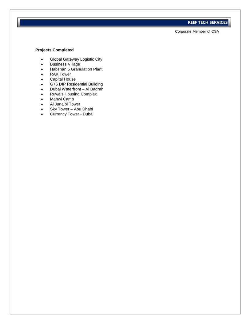
International Operations Business Group
Corporate Member of CSA
REEF TECH SERVICES
Projects Completed
Global Gateway Logistic City
Business Village
Habshan 5 Granulation Plant
RAK Tower
Capital House
G+6 DIP Residential Building
Dubai Waterfront – Al Badrah
Ruwais Housing Complex
Mahwi Camp
Al Junaibi Tower
Sky Tower – Abu Dhabi
Currency Tower - Dubai
International Operations Business Group
Corporate Member of CSA
REEF TECH SERVICES
Operational Procedures
International Operations Business Group
Corporate Member of CSA
REEF TECH SERVICES
CONTENTS
1. Responsibilities
2. Commissioning Proformas
3. Commissioning Controls Procedures
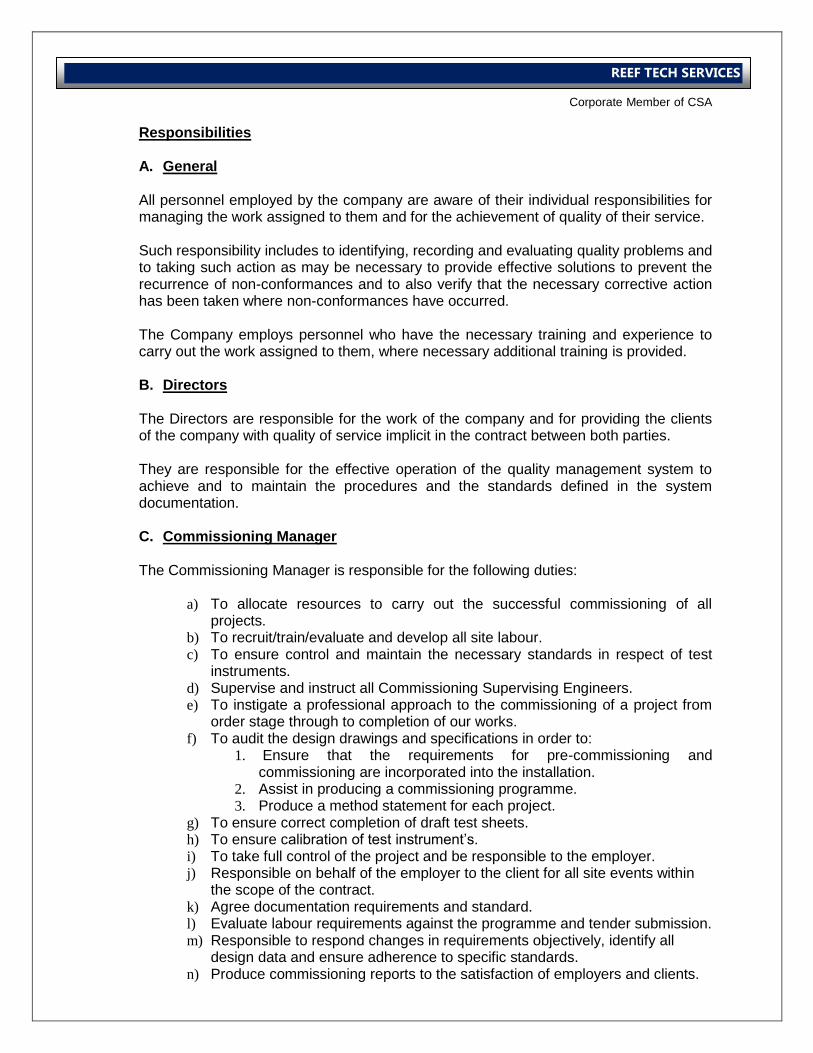
International Operations Business Group
Corporate Member of CSA
REEF TECH SERVICES
Responsibilities A. General All personnel employed by the company are aware of their individual responsibilities for managing the work assigned to them and for the achievement of quality of their service. Such responsibility includes to identifying, recording and evaluating quality problems and to taking such action as may be necessary to provide effective solutions to prevent the recurrence of non-conformances and to also verify that the necessary corrective action has been taken where non-conformances have occurred. The Company employs personnel who have the necessary training and experience to carry out the work assigned to them, where necessary additional training is provided. B. Directors The Directors are responsible for the work of the company and for providing the clients of the company with quality of service implicit in the contract between both parties. They are responsible for the effective operation of the quality management system to achieve and to maintain the procedures and the standards defined in the system documentation. C. Commissioning Manager The Commissioning Manager is responsible for the following duties:
a) To allocate resources to carry out the successful commissioning of all projects.
b) To recruit/train/evaluate and develop all site labour. c) To ensure control and maintain the necessary standards in respect of test
instruments. d) Supervise and instruct all Commissioning Supervising Engineers. e) To instigate a professional approach to the commissioning of a project from
order stage through to completion of our works. f) To audit the design drawings and specifications in order to:
1. Ensure that the requirements for pre-commissioning and commissioning are incorporated into the installation.
2. Assist in producing a commissioning programme. 3. Produce a method statement for each project.
g) To ensure correct completion of draft test sheets. h) To ensure calibration of test instrument’s. i) To take full control of the project and be responsible to the employer. j) Responsible on behalf of the employer to the client for all site events within
the scope of the contract. k) Agree documentation requirements and standard. l) Evaluate labour requirements against the programme and tender submission. m) Responsible to respond changes in requirements objectively, identify all
design data and ensure adherence to specific standards. n) Produce commissioning reports to the satisfaction of employers and clients.
International Operations Business Group
Corporate Member of CSA
REEF TECH SERVICES
o) Review and evaluate commissionability of design to minimize time taken on site, ensure client satisfaction with the end product and maximize company efficiency.
p) Produce technical reports and hold discussions with designers to improve commissionability.
q) Evaluate the technical aspects of method statements for specialists, understand and apply the requirements for correct instrumentation in checking and witnessing specialist’s work.
r) Responsible for all aspects of site including risk assessment, method statements and tool box talks.
s) Fully aware of company’s policies in respect of contractual commitments. t) Responsible for achieving successful completion of the project
D. Engineers Responsibilities
The engineer in charge is assigned the following responsibilities for a particular project:
a) Responsible for other people on site. b) Labour/daily report to reading office. c) To ensure that the commissioning progress proceeds logically and
systematically to a satisfactory conclusion, within the confines of the instructions and in line with the method statement for the project.
d) To inspect the installation prior to commencement to ensure that the installation is complete and ready for commissioning.
e) Liaise with client and other specialists to assist in the satisfactory completion of commissioning.
f) Allocate work and supervise the commissioning technicians to ensure efficient completion of air and water balancing of systems.
g) To arrange for the witnessing of individual systems and ensure that all tests sheets and completion certificates are signed by the clients respective without delay.
h) Compile a file of all test results and signed documentation to form the record of the works.
i) Maintain a daily diary of events and produce a regular report to the Commissioning Manager of progress.
j) Report on any disruption to the works and seek instructions from Immediate Supervisor or the office.
k) Report any defects or shortfall on system/plant performance and seek instructions.
Commissioning Proformas
The company system contains a range of standard proformas covering all aspects of the commissioning of an HVAC installations, to ensure that all checks, tests, and equipment information are correctly recorded. These proformas are as follows:
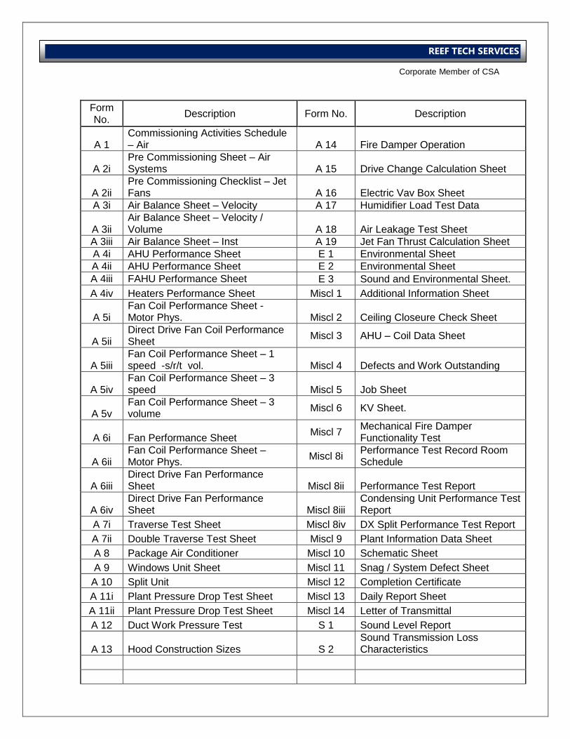
International Operations Business Group
Corporate Member of CSA
REEF TECH SERVICES
Form No.
Description Form No. Description
A 1 Commissioning Activities Schedule – Air A 14 Fire Damper Operation
A 2i Pre Commissioning Sheet – Air Systems A 15 Drive Change Calculation Sheet
A 2ii Pre Commissioning Checklist – Jet Fans A 16 Electric Vav Box Sheet
A 3i Air Balance Sheet – Velocity A 17 Humidifier Load Test Data
A 3ii Air Balance Sheet – Velocity / Volume A 18 Air Leakage Test Sheet
A 3iii Air Balance Sheet – Inst A 19 Jet Fan Thrust Calculation Sheet
A 4i AHU Performance Sheet E 1 Environmental Sheet
A 4ii AHU Performance Sheet E 2 Environmental Sheet
A 4iii FAHU Performance Sheet E 3 Sound and Environmental Sheet.
A 4iv Heaters Performance Sheet Miscl 1 Additional Information Sheet
A 5i Fan Coil Performance Sheet - Motor Phys. Miscl 2 Ceiling Closeure Check Sheet
A 5ii Direct Drive Fan Coil Performance Sheet
Miscl 3 AHU – Coil Data Sheet
A 5iii Fan Coil Performance Sheet – 1 speed -s/r/t vol. Miscl 4 Defects and Work Outstanding
A 5iv Fan Coil Performance Sheet – 3 speed Miscl 5 Job Sheet
A 5v Fan Coil Performance Sheet – 3 volume
Miscl 6 KV Sheet.
A 6i Fan Performance Sheet Miscl 7
Mechanical Fire Damper Functionality Test
A 6ii Fan Coil Performance Sheet – Motor Phys.
Miscl 8i Performance Test Record Room Schedule
A 6iii Direct Drive Fan Performance Sheet Miscl 8ii Performance Test Report
A 6iv Direct Drive Fan Performance Sheet Miscl 8iii
Condensing Unit Performance Test Report
A 7i Traverse Test Sheet Miscl 8iv DX Split Performance Test Report
A 7ii Double Traverse Test Sheet Miscl 9 Plant Information Data Sheet
A 8 Package Air Conditioner Miscl 10 Schematic Sheet
A 9 Windows Unit Sheet Miscl 11 Snag / System Defect Sheet
A 10 Split Unit Miscl 12 Completion Certificate
A 11i Plant Pressure Drop Test Sheet Miscl 13 Daily Report Sheet
A 11ii Plant Pressure Drop Test Sheet Miscl 14 Letter of Transmittal
A 12 Duct Work Pressure Test S 1 Sound Level Report
A 13 Hood Construction Sizes S 2 Sound Transmission Loss Characteristics
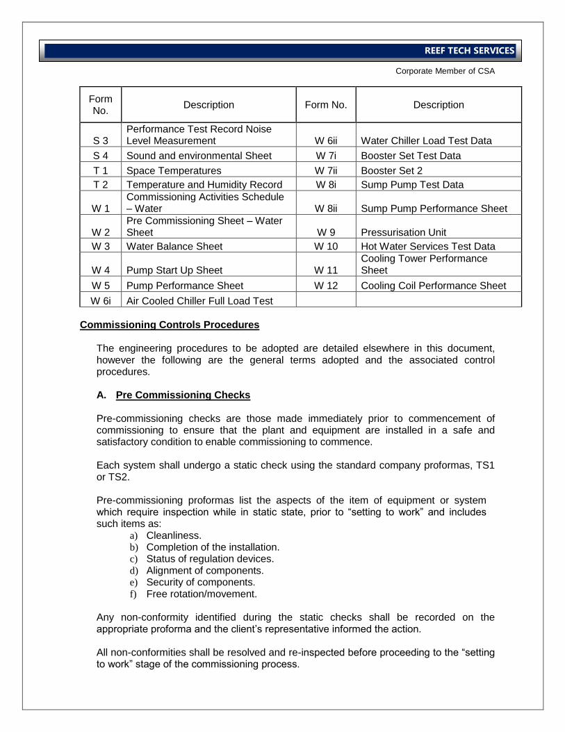
International Operations Business Group
Corporate Member of CSA
REEF TECH SERVICES
Form No.
Description Form No. Description
S 3 Performance Test Record Noise Level Measurement W 6ii Water Chiller Load Test Data
S 4 Sound and environmental Sheet W 7i Booster Set Test Data
T 1 Space Temperatures W 7ii Booster Set 2
T 2 Temperature and Humidity Record W 8i Sump Pump Test Data
W 1 Commissioning Activities Schedule – Water W 8ii Sump Pump Performance Sheet
W 2 Pre Commissioning Sheet – Water Sheet W 9 Pressurisation Unit
W 3 Water Balance Sheet W 10 Hot Water Services Test Data
W 4 Pump Start Up Sheet W 11 Cooling Tower Performance Sheet
W 5 Pump Performance Sheet W 12 Cooling Coil Performance Sheet
W 6i Air Cooled Chiller Full Load Test
Commissioning Controls Procedures
The engineering procedures to be adopted are detailed elsewhere in this document, however the following are the general terms adopted and the associated control procedures. A. Pre Commissioning Checks Pre-commissioning checks are those made immediately prior to commencement of commissioning to ensure that the plant and equipment are installed in a safe and satisfactory condition to enable commissioning to commence. Each system shall undergo a static check using the standard company proformas, TS1 or TS2. Pre-commissioning proformas list the aspects of the item of equipment or system which require inspection while in static state, prior to “setting to work” and includes such items as:
a) Cleanliness. b) Completion of the installation. c) Status of regulation devices. d) Alignment of components. e) Security of components. f) Free rotation/movement.
Any non-conformity identified during the static checks shall be recorded on the appropriate proforma and the client’s representative informed the action. All non-conformities shall be resolved and re-inspected before proceeding to the “setting to work” stage of the commissioning process.
International Operations Business Group
Corporate Member of CSA
REEF TECH SERVICES
B. Setting to Work The “setting to work” of a system is defined as the process of setting a static system into motion. It is essential for systems comprising of a number of items of equipment or sub-systems, that the “setting to work” of each component of the system be carried out systematically. The sequence of activities must therefore be identified on the commissioning programme or logic diagram. The priorities for the “setting to work” of individual components within a system will normally be as follows:
a) Frost protection and other such protective devices. b) Water tanks.
c) Water softener/demineralisation systems. d) Pressurisation/water nake-up units. e) Circulating pumps/air handling units. f) Boilers, chillers/cooling towers g) Secondary equipment-calorifiers, humidifier, heater. h) Controls.
Note Unless forming part of the vital protection or interlocking function, controls are normally by-passed and the system manually adjusted or statically set during the “setting-to-work” phase of commissioning. Provided adequate planning and co-ordination is achieved, the commissioning of controls is one of the few activities which may proceed in parallel with the overall commissioning process. Final commissioning of HVAC controls will normally only be possible after the completion of both the “setting-to-work” and regulating phases of individual systems. Before proceeding with the act of “setting to work” an item of equipment or system, the Engineer in charge shall ensure that:
a) All pre-commissioning checks and proformas are complete. b) All non-conformities are resolved. c) All electrical checks are complete. d) Mains water/gas/electricity are available. e) All essential interlocks/safety devices are operational. f) He is familiar with the operation of the complete system. g) Before starting the regulation, it is essential that the building is complete,
ceilings, partitions, doors and windows installed, windows glazed, doors or windows in their normal or closed state.
h) All site personnel are made aware of the commissioning activities and that they are not affected.
i) Adequate warning signs are displayed. j) If required by the conditions on site, a permit-to-work system has been set
up.
International Operations Business Group
Corporate Member of CSA
REEF TECH SERVICES
The initial running of any prime mover shall be carried out under strict control and limited load conditions, by adjusting the system flow rates. In addition, the “setting to work” of equipment shall be broken down into the following distinct stages:
a) Initial start/stop (check direction of rotation). b) Initial run on light load. c) Starting at normal load. d) Running-in period (normal load)
During the running-in period the Commissioning Engineer shall complete the appropriate equipment checks and test proformas and compare the actual data obtained under normal load running conditions with that of the design data. Any malfunction of the equipment or non-conformity between actual design data shall be analyzed and a solution obtained before proceeding with regulating phase of the commissioning process. Any equipment which is unable to achieve the design requirements with the regulation devices in a “fully open” position prior to regulation of the system will almost certainly require up-grading. Where possible, up-grading of the equipment shall take place prior to the regulating of the system. Details of “setting to work” of individuals system are detailed elsewhere in this statement. The inspection authority shall be asked to witness and sign the completed equipment performance test proformas. C. Regulation and Balancing of Distribution Systems Regulation is the process of adjusting a system within specific tolerances. Regulations of a system shall not commence until the satisfactory completion of:
a) All pre-commissioning checks and proformas. b) The “setting to work” of all associated equipment.
All regulating and balancing of air and water distribution systems shall be carried out in line with one or more of the following guides:
a) CIBSE Commissioning Codes for Air and Water. b) BSRIA Application Guides Nos. 2/89, 3/89 and 1/91.
The Engineer in charge shall ensure that he is fully conversant with every aspect of the above codes of practice. The final results of regulating a distribution system shall be recorded on the standard company or other approved proformas and signed and dated by the Engineer concerned at the time of carrying out the regulation.
International Operations Business Group
Corporate Member of CSA
REEF TECH SERVICES
Proformas used to record commissioning results shall be the company proformas on all projects except where the client decrees otherwise. Any non-conformity in the regulation of a system shall be analyzed and corrective adjustment or action taken by the Commissioning Engineer immediately. The Commissioning Engineer shall be responsible for informing the client’s Supervising Engineer of the failure of a system to achieve an acceptable standard of regulation. On ascertaining the reason for the non-conformity, the Commissioning Engineer shall report in writing, stating the reason and recommending any corrective action necessary to resolve the matter. The client’s representative shall be responsible for arranging any action necessary to resolve the non-conformity and shall inform the engineer in charge when the corrective action has been taken. After satisfactory regulation of the distribution system and completion of the appropriate proformas, the engineer in charge shall arrange for the witnessing of the system by the client’s representative or the appointed inspecting authority. D. Achievement of Conformity at Commissioning The process of undertaking the regulating and balancing of a system will identify any non-conformity in respect of fluid flow and circulation. The responsibility of the company will be to identify the non-conformity, notify the client’s representative, offer any relevant information in respect of the likely cause of the non-conformity and establish the necessary rectifying actions. The responsibility in respect of initiating any rectifying action will always lie with the client. The likely cause of any non-conformity is likely to be due to one or more of the following:
a) An error in conceptual design. b) An error in system design. c) An error in detailed design. d) An error in equipment selection. e) Shortcomings in supplied equipment. f) Changes in system geometry imposed during the installation. g) Changes in system geometry imposed by variations. h) Sub-standard workmanship. i) Dirty pipework or inadequate water treatment.
International Operations Business Group
Corporate Member of CSA
REEF TECH SERVICES
The solutions to the non-conformity are likely to involve one or more of the following actions:
a) Modification of the installation. b) Replacement of equipment. c) Concession by the client. d) Cleaning of pipe work and review of the water treatment.
E. Witnessing and Signing of Results After the satisfactory completion of the commissioning of an individual system, the Engineer in charge shall ensure that the relevant documentation is complete and free from error, before arranging for witnessing by the inspection authority. The Engineer in charge shall be responsible for ensuring that the inspecting authority is notified of the readiness of a system for witnessing and at the same time, submit a copy of all relevant results for preliminary inspection. Adequate notice shall be given to the inspecting authority of a request for witnessing. The method statement may specify a minimum period of notification prior to witnessing. It is essential that every effort be taken to ensure that the witnessing of a system by the inspecting authority be instigated immediately following satisfactory commissioning. The Engineer in Charge shall inform the client’s representative of the completion of the commissioning of a system, and the client shall be responsible for ensuring that every effort be taken to protect the system from interference prior to witnessing taking place. After successful witnessing of the system, it shall be the responsibility of the Engineer in Charge to obtain the signature of acceptance from the inspecting authority. In the unlikely event of the inspecting authority not signing acceptance of the system, the Engineer shall confirm in writing the successful witnessing of the system and request confirmation by the inspecting authority. Witnessing of individual items of equipment or component parts of an overall system shall, where possible, follow on systematically and within a reasonable time period. Under no circumstances shall the signing of an accepted system by the inspecting authority be delayed until after the satisfactory completion of all the commissioning activities. Where possible, any system which is dependent upon another shall be signed “subject to” the satisfactory completion of that system.
International Operations Business Group
Corporate Member of CSA
REEF TECH SERVICES
All documents shall be held in a secure place, and on completion of the witnessing of a total system, an acceptance certificate shall be issued and signed by the Inspection Authority. F. Post Commissioning Activities The commissioning is not deemed to be complete until the following activities have been completed:
a.) Making good the installation.
b.) Test documentation finalized and handed to client.
Making Good The Engineer in charge shall be responsible for ensuring that the following aspects are made good immediately following the satisfactory completion of the commissioning:
a) All ductwork test plugs are fitted. a.) Pipework test points are plugged. b.) Access doors/manholes are replaced. c.) Pulley guards are replaced. d.) Controls/panels are re-installed. e.) Inhibiting devices are removed. f.) Ceiling tiles replaced (if removed by Engineer) g.) Insulation or other damage reported to Project Manager. h.) All controls and equipment set to operate in auto. i.) Temporary equipment removed. j.) All regulating device positions marked and/or recorded on the
appropriate proformas. k.) Gauges replaced. l.) Controls and equipment covers replaced. m.) Any other aspect of the installation requiring rectification as a result of
commissioning.
International Operations Business Group
Corporate Member of CSA
REEF TECH SERVICES
Air System Procedure
International Operations Business Group
Corporate Member of CSA
REEF TECH SERVICES
CONTENTS
CONSTANT VOLUME SYSTEMS
1. Pre Commissioning
2. Setting to Work.
3. Regulation of Air Flow.
4. Summary.
VARIABLE VOLUME SYSTEM
1. Initial Actions.
2. Testing the Systems.
3. Setting up for Automatic Control.
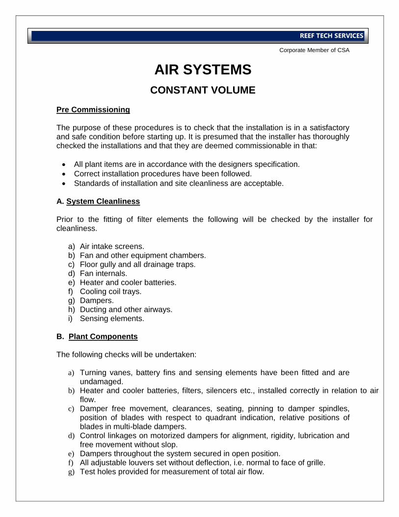
International Operations Business Group
Corporate Member of CSA
REEF TECH SERVICES
AIR SYSTEMS
CONSTANT VOLUME
Pre Commissioning
The purpose of these procedures is to check that the installation is in a satisfactory and safe condition before starting up. It is presumed that the installer has thoroughly checked the installations and that they are deemed commissionable in that:
All plant items are in accordance with the designers specification.
Correct installation procedures have been followed.
Standards of installation and site cleanliness are acceptable. A. System Cleanliness Prior to the fitting of filter elements the following will be checked by the installer for cleanliness.
a) Air intake screens. b) Fan and other equipment chambers. c) Floor gully and all drainage traps. d) Fan internals. e) Heater and cooler batteries. f) Cooling coil trays. g) Dampers. h) Ducting and other airways. i) Sensing elements.
B. Plant Components
The following checks will be undertaken:
a) Turning vanes, battery fins and sensing elements have been fitted and are undamaged.
b) Heater and cooler batteries, filters, silencers etc., installed correctly in relation to air flow.
c) Damper free movement, clearances, seating, pinning to damper spindles, position of blades with respect to quadrant indication, relative positions of blades in multi-blade dampers.
d) Control linkages on motorized dampers for alignment, rigidity, lubrication and free movement without slop.
e) Dampers throughout the system secured in open position. f) All adjustable louvers set without deflection, i.e. normal to face of grille. g) Test holes provided for measurement of total air flow.
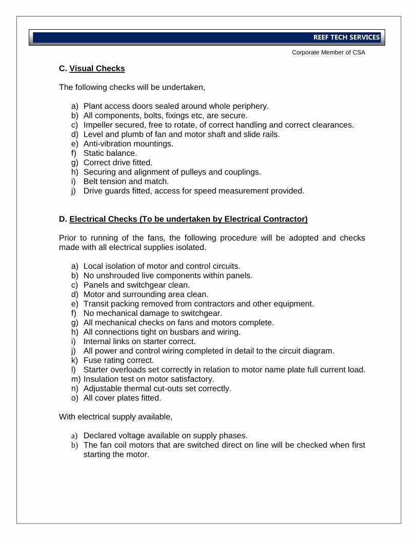
International Operations Business Group
Corporate Member of CSA
REEF TECH SERVICES
C. Visual Checks The following checks will be undertaken,
a) Plant access doors sealed around whole periphery. b) All components, bolts, fixings etc, are secure. c) Impeller secured, free to rotate, of correct handling and correct clearances. d) Level and plumb of fan and motor shaft and slide rails. e) Anti-vibration mountings. f) Static balance. g) Correct drive fitted. h) Securing and alignment of pulleys and couplings. i) Belt tension and match. j) Drive guards fitted, access for speed measurement provided.
D. Electrical Checks (To be undertaken by Electrical Contractor) Prior to running of the fans, the following procedure will be adopted and checks made with all electrical supplies isolated.
a) Local isolation of motor and control circuits. b) No unshrouded live components within panels. c) Panels and switchgear clean. d) Motor and surrounding area clean. e) Transit packing removed from contractors and other equipment. f) No mechanical damage to switchgear. g) All mechanical checks on fans and motors complete. h) All connections tight on busbars and wiring. i) Internal links on starter correct. j) All power and control wiring completed in detail to the circuit diagram. k) Fuse rating correct. l) Starter overloads set correctly in relation to motor name plate full current load. m) Insulation test on motor satisfactory. n) Adjustable thermal cut-outs set correctly. o) All cover plates fitted.
With electrical supply available,
a) Declared voltage available on supply phases. b) The fan coil motors that are switched direct on line will be checked when first
starting the motor.
International Operations Business Group
Corporate Member of CSA
REEF TECH SERVICES
Setting to Work. A. Precautions against airborne dirt Others shall have cleaned the system internally, and verification obtained from the Supervising engineer. B. Initial Running of Fan Set To reduce the initial load, main plant damper should be partially closed to reduce the possibility of overloading. On activating the motor we will check:
a) Direction of rotation of motor shaft. b) Motor, drive and fan free from vibration or undue noise. c) Motor starting current for sequence timing adjustment. d) Motor running current on all phases.
1. Initial Run The light load will be sustained for an initial period until the Commissioning Engineer is satisfied that stable conditions exist, there after further load shall be applied until full load is established. 2. Normal Load Running On conclusion of the initial running period and normal load being achieved, the unit will be stopped and restarted at normal starting load, and the running checks repeated. A running in period will now be established until the Commissioning Engineer is satisfied that the fan can be placed under the normal operation system. Regulation of Air Flow A. Method of Measurement All airflows will be based upon in duct measurement of velocity pressure using manometer and pitot tubes. Vane anemometers will be used to balance between similar air inlets and outlets on a comparative basis, and corrected by comparison to in duct velocity measurements. All other instrumentation and measuring techniques will be as described in BSRIA Application Guide 3/89.
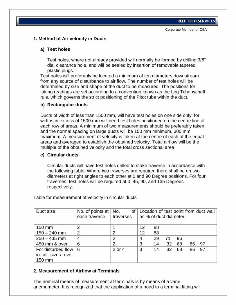
International Operations Business Group
Corporate Member of CSA
REEF TECH SERVICES
1. Method of Air velocity in Ducts
a) Test holes Test holes, where not already provided will normally be formed by drilling 3/8” dia. clearance hole, and will be sealed by insertion of removable tapered plastic plugs.
Test holes will preferably be located a minimum of ten diameters downstream from any source of disturbance to air flow. The number of test holes will be determined by size and shape of the duct to be measured. The positions for taking readings are set according to a convention known as the Log Tchebycheff rule, which governs the strict positioning of the Pitot tube within the duct.
b) Rectangular ducts
Ducts of width of less than 1500 mm, will have test holes on one side only, for widths in excess of 1500 mm will need test holes positioned on the centre line of each row of areas. A minimum of two measurements should be preferably taken, and the normal spacing on large ducts will be 150 mm minimum, 300 mm maximum. A measurement of velocity is taken at the centre of each of the equal areas and averaged to establish the obtained velocity. Total airflow will be the multiple of the obtained velocity and the total cross sectional area.
c) Circular ducts Circular ducts will have test holes drilled to make traverse in accordance with the following table. Where two traverses are required there shall be on two diameters at right angles to each other at 0 and 90 Degree positions. For four traverses, test holes will be required at 0, 45, 90, and 135 Degrees respectively.
Table for measurement of velocity in circular ducts
2. Measurement of Airflow at Terminals The nominal means of measurement at terminals is by means of a vane anemometer. It is recognized that the application of a hood to a terminal fitting will
Duct size No. of points at each traverse
No. of traverses
Location of test point from duct wall as % of duct diameter
150 mm 2 1 12 88
150 – 240 mm 2 2 12 88
250 – 435 mm 4 2 4 29 71 96
450 mm & over 6 2 3 14 32 68 86 97
For disturbed flow in all sizes over 150 mm
6 2 or 4 3 14 32 68 86 97
International Operations Business Group
Corporate Member of CSA
REEF TECH SERVICES
slightly increase the system resistance and thus reduce the discharge rate at the terminal. It is general that the resistance of the instrument will be small, and the application of a correction factor developed of an instrument in the particular application will make an adequate adjustment. The correction factor will be determined by comparison of the anemometer reading to an absolute reading, in practice probably a duct pitot traverse at a location producing stable airflow, using a calibrated instrument for the measurement refer Test pro-formas for correction factor. The preferred situation is that in any balancing exercise only one instrument is used. In some instances, because of a wide diversity in airflows from terminals and significant differences in size and type of terminal on the one system, more than one instrument may have to be used. This may be unavoidable, and can be acceptable provided full consideration is given to the preparation of the correction factors. Although the primary effect of the use of the instrument will be to depress the measured value i.e. producing a correction factor > 1, because in the application, the factor will compensate for instrument variation as well as the instrument effect, the final factor may often be < 1. In practice correction factors that fall within a range of + 20 %, would be anticipated. If correction factors exceed these parameters, they need not be rejected, but an explanation of why such a wider deviation has occurred needs to be appraised. The intelligent application of experience and a sound technical knowledge is required from the test technician in evaluating the acceptability of his correction factors. If there is a wide variation in type of outlet on a system, it may be prudent to develop a different factor for each type. B. Regulation procedure Before starting the regulation, it is essential that the building is complete, ceiling, partition doors and windows installed, windows glazed, doors or windows in their normal or closed state. If spaces are not architecturally sealed, abnormal pressure distributions will unbalance the system and lead to inconsistent and un-reproducible results. 1. Proportional Balancing The method of regulation will be the proportional method as set out in CIBSE Code A.
The successful application of the proportional technique is dependant upon the inclusion of sufficient regulating dampers, suitably positioned in the ductwork system.
International Operations Business Group
Corporate Member of CSA
REEF TECH SERVICES
The premise for the procedure is that in any branch element of the system, the quantity of air passing through each terminal will represent a proportion of the total flow in the branch. Unless the terminal regulating dampers are altered, these proportions will remain the same, within practical limits, whatever the flow rate in the branch.
To balance one terminal against another it is, therefore only necessary to adjust the regulating dampers so that the terminals share the flow in correct proportions. It is not of the significance what the actual flow is during the interim regulation. Then the main flow from the fan is regulated to its design value, each terminal should also be passing at its design flow rate, since each has been set to take its own proportionate share. a) Index branch and least favored branch Care should be taken in differentiating between the index branch and the least favoured branch in carrying out the balancing process. Whilst nominally they have a similar definition, they need not be the same in practice.
Index branch This is defined as the branch which, with the system in an unbalanced state i.e. all dampers fully open, has the greatest resistance relative to its design flow rate when compared with the other branches forming part of the same system. A branch may have a number of sub branches. For each branch there will be an index sub branch, similarly each sub branch may have a number of terminals, one of which will be the index. Once established, an index branch will be known as such throughout the balancing process. At the end of the process, there should be a clear path from the fan to the index terminal, where all regulating devices are set full open. There is a need to provide for the circumstance where the index is not the most remote terminal. In proportional balancing, it is essential that on a system or sub system being balanced, that the most remote terminals must initially be regulated down until it is made equal to the index. When this is done the most remote terminal can be regarded as equivalent to the index. The true index has its regulating damper fully open and must remain so, but the most remote terminal is the reference index terminal for the balancing procedure. b) Preliminaries
a) Open all duct system and terminal dampers, ensuring that the fan output can be limited and an overload situation does not occur. Set all diffuser cones to give full downward discharge, Set adjustable grille louvers at right angles to the grille face. Set plant dampers to a non-modulating position preferably full fresh air/discharge.
International Operations Business Group
Corporate Member of CSA
REEF TECH SERVICES
b) Run the fan and check the motor current. Ensure that its design full load value is not exceeded. Adjust the main fan damper until the fan motor current is close to the design value.
c) Undertake preliminary inspection checking that air flowing at each terminal. Any dead terminals or branches should be investigated.
d) Measure the total flow rate at the fan by a duct pitot traverse, the fan head and rotating speed. The fan should be delivering at 110% of the design value.
c) Rough balancing of branches
Measure the flow in the main branches A B & C. Having worked out the percentage of design flow rate for each branch, determine which branch is the index, i.e. the one with the lowest percentage of its design flow rate. If this is not the most remote (branch A), then adjust the flow to branch A until it has just the lowest percentage flow rate relative to the index. If the difference between the highest and lowest percentage flow rates for the branches is more than 30 %, adjust the dampers to bring the flow rates within this limit but still maintaining branch A as the one with the lowest percentage flow rate. Once the main branches are in a rough state of balance, the sub branches should be tackled next. Starting with the most remote branch (branch A), measure the flow rate in the entire sub branches A1, A2, A3 etc. Check that the sum total of all the sub branch flow rate equals the main branch flow rate already measured. Any large discrepancy should be investigated. Work out the percentage flow rates for each branch and check that the most remote (A5) is the lowest. If not, make A5 the least favored by dampening down. Again, check all branches on branch A to see that their percentage design flow rates are reasonably close to each other. If the highest and lowest values are more than 30% apart, adjust the appropriate dampers to bring them nearer together. Repeat the coarse balancing of sub branches for each of the remaining main branches, B and C. Check the total flow rates in the main branches again and adjust if necessary to make the most remote (A) the least favored. Sum the main branch flow rates to check that the total flow rate in the system is not less than 110% of design. If the total flow has dropped below 110% of design, adjust the main damper accordingly or increase the fan speed. d) Balancing Terminals Any main branch may be chosen to start with but given a free choice, and having carried out a rough balance of main and sub branches, start with the most remote branch and then sub branch, i.e. A5 in figure on page. Locate the terminal, which is discharging the lowest percentage of its design flow rate. This is generally the last terminal in the run. If it is not , adjust the damper in the last terminal unit until it is working with the same percentage flow as the lowest one previously measured.
International Operations Business Group
Corporate Member of CSA
REEF TECH SERVICES
Measure the flow from the terminal next to the index and work out the percentage flow. Adjust the damper to make the percentage flow as close as possible to that of the index. Fix the damper in position. Repeat the procedure for the next terminal, again comparing it with the index. As the dampers are closed along the run, more air will be given to the downstream terminals and the volume of air discharged at the terminal index will rise. This does not affect the balancing procedure since each terminal being adjusted is related in turn with the index. When all the terminals have been balanced on a sub branch, each terminal will be running with an equal percentage of the design rate, within the allowable tolerances. The flow rates at each terminal must be measured and recorded. Once again a summation should be made to check that the total is in reasonable agreement with the measured sub branch flow. e) Balancing Sub-Branches When all the terminals on each sub branch have been brought into balance, the sub- branches should be brought into balance with one another using the same techniques as for the terminals. Ideally this is done by traversing each sub branch first to determine the index sub branch, which should be the remote. Again, if the one end is not the index, then it must be made the least favored by dampening down. Having made the initial traverses by pitot tube to establish absolute flow rates, it is often possible to speed up the process of regulation by one of two methods to save repeated traversing. If the traversing stations are well downstream of sub branch balancing dampers, and a centre point reading of static pressure is of reasonable size, then, using the square law relationship between static pressure and flow rate, the flow rates can be simply adjusted using static pressure measurements. If the sub branches each have a similar type of terminal, then a single terminal on each branch can be used to obtain an anemometer reading as a basis for bringing the sub branches into balance. It should be noted that the two techniques described above should be used with great caution and, in any case, only when, the sub branches have been brought into fairly close balance by the initial course balancing procedure. f) Balancing Branches The main branches (A, B and C) are brought into balance by the same method as for the sub branches. As with the sub branches, suitable static pressure measurements in each branch can be used to bring the branches more quickly into balance but final results must be obtained by pitot traversing.
International Operations Business Group
Corporate Member of CSA
REEF TECH SERVICES
C. Final Correlation When the entire duct network is balanced, measure the total flow in the main duct using a pitot tube and manometer. If the flow is higher than the design value, adjust the main damper. If the pressure drop across the main damper in the final position is a significant part of the total system pressure drop, a reduction in fan speed should be considered. If the flow is less than the design rating, open the damper, making sure that the maximum permissible fan motor current is not exceeded. If the flow rate is less than the design rating, open the damper, making sure that the maximum permissible fan motor current is not exceeded. It is essential, whilst using the proportional balancing technique, that absolute flow rates are calculated from time to time during the procedure and at the end in order to ensure that there is satisfactory correlation between the flow rates from terminals in sub branches and branches and the total system flow rate. Due to the wide variety and mix of terminals, which can be available on any one system, flow rate techniques may vary. Simply balancing on anemometer velocity readings alone, without continual reference to absolute values, can lead to poor results. Finally, recheck all terminals in terms of the percentage of design. If a section is shown to be out of balance, dampers can be reset, provided the flow in adjacent sections is not changed beyond the tolerance limits. This recheck will also serve as the record of the final state of the balance of the system. Lock all dampers in position. Alternatively, scribe the position of the damper arm and seal the operating screw. Finally, adjustable louvers and cones on terminal grilles and diffusers shall be set to positions as predetermined and specified by the designer. Summary The most important principle in proportional balancing is that damper adjustment must always start with the terminal next to the last in a group of terminals, or with the sub branch next to the last when balancing the duct system, and continue along the duct in the direction of the fan. Never adjust a damper, whether on a terminal or a branch or a sub branch, until all related dampers more remote from the fan have been set. Setting Plant Volumes It is common practice to reduce energy consumption by mixing return and fresh air flows whilst maintaining the minimum fresh air make up to meet ventilation requirements.

International Operations Business Group
Corporate Member of CSA
REEF TECH SERVICES
Modulating dampers are generally provided at fresh air inlet, exhaust discharge and recirculation. Limits to damper operation must be set to achieve the minimum fresh/recirculation airflows. Preferred method for measurement of airflow would be by duct pitot traverse of duct openings by vane anemometer may be possible. Approximate settings may only be possible, achieved by comparison of inlet and mixed air temperatures.
International Operations Business Group
Corporate Member of CSA
REEF TECH SERVICES
AIR SYSTEM VARIABLE AIR VOLUME
Initial Actions a) Establish the minimum static pressure required at the V.A.V. terminal inlet.
This should be obtainable from the unit’s supplier. The figure quoted is often in terms of a differential pressure. In this case either check a sample of units to establish the likely downstream resistance or approach the system designer for their best estimate.
b) Ensure that you have the facility to manually control the supply fan so that you can increase/decrease its duly as necessary.
It can usually be arranged for this to be available to the commissioning engineer, but in some needs the input of the control engineer. Make sure that all interested parties are aware of the need for CONTINUAL attendance if this is the case.
c) Ensure that you have the facility to manually drive the V.A.V. terminals between maximum and minimum
The current fashion for “intelligent” V.A.V. terminals often means that the controls engineer’s input is necessary for this function. Again make sure that everybody is aware of the need for continual attendance if this is the case.
d) Agree with the consultant engineer/designer on the number of terminals where individual pitot traverse volumes will be used to crosscheck calibration results.
This is usually 10-15%, providing that there is a means of obtaining airflow measurements from the terminal. e.g. voltage from hot wire type velocity sensors or velocity pressure from flow grids. There are still some types of terminals where the only means of proving the duly is to duct volumes by pitot transverse. It is also the case that very few, if any, systems have the necessary ductwork configuration for accurate volumes on all terminals.
e) Establish the degree of “diversity” built into the system and agree with the designer on the way in which the diversity is to applied.
Very few fans are sized to provide the duly necessary to satisfy all of the terminals at maximum volume. The shortfall (diversity) is usually taken care of by selling some terminals at minimum for the final fan test. This can be done by shutting down entire branches terminals or by closing down a small number of terminals on several branches. It is usually the case that the terminals nearest the fan are closed so as to prove the fan against the “worst case”, i.e. making it satisfy maximum demand at index terminals.
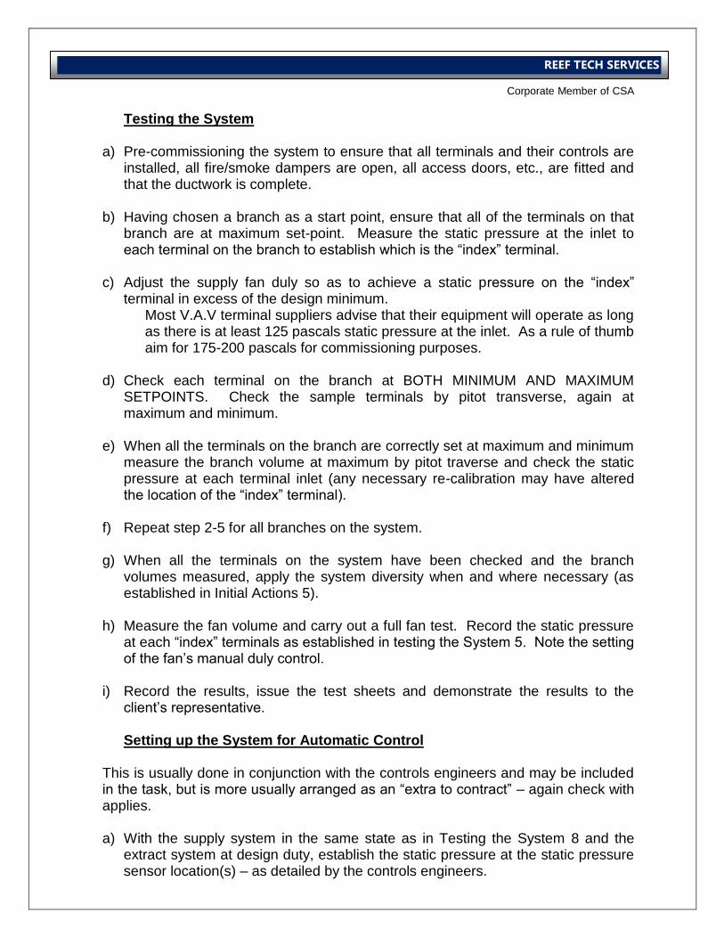
International Operations Business Group
Corporate Member of CSA
REEF TECH SERVICES
Testing the System
a) Pre-commissioning the system to ensure that all terminals and their controls are installed, all fire/smoke dampers are open, all access doors, etc., are fitted and that the ductwork is complete.
b) Having chosen a branch as a start point, ensure that all of the terminals on that branch are at maximum set-point. Measure the static pressure at the inlet to each terminal on the branch to establish which is the “index” terminal.
c) Adjust the supply fan duly so as to achieve a static pressure on the “index”
terminal in excess of the design minimum. Most V.A.V terminal suppliers advise that their equipment will operate as long as there is at least 125 pascals static pressure at the inlet. As a rule of thumb aim for 175-200 pascals for commissioning purposes.
d) Check each terminal on the branch at BOTH MINIMUM AND MAXIMUM SETPOINTS. Check the sample terminals by pitot transverse, again at maximum and minimum.
e) When all the terminals on the branch are correctly set at maximum and minimum measure the branch volume at maximum by pitot traverse and check the static pressure at each terminal inlet (any necessary re-calibration may have altered the location of the “index” terminal).
f) Repeat step 2-5 for all branches on the system.
g) When all the terminals on the system have been checked and the branch
volumes measured, apply the system diversity when and where necessary (as established in Initial Actions 5).
h) Measure the fan volume and carry out a full fan test. Record the static pressure
at each “index” terminals as established in testing the System 5. Note the setting of the fan’s manual duly control.
i) Record the results, issue the test sheets and demonstrate the results to the
client’s representative. Setting up the System for Automatic Control
This is usually done in conjunction with the controls engineers and may be included in the task, but is more usually arranged as an “extra to contract” – again check with applies. a) With the supply system in the same state as in Testing the System 8 and the
extract system at design duty, establish the static pressure at the static pressure sensor location(s) – as detailed by the controls engineers.
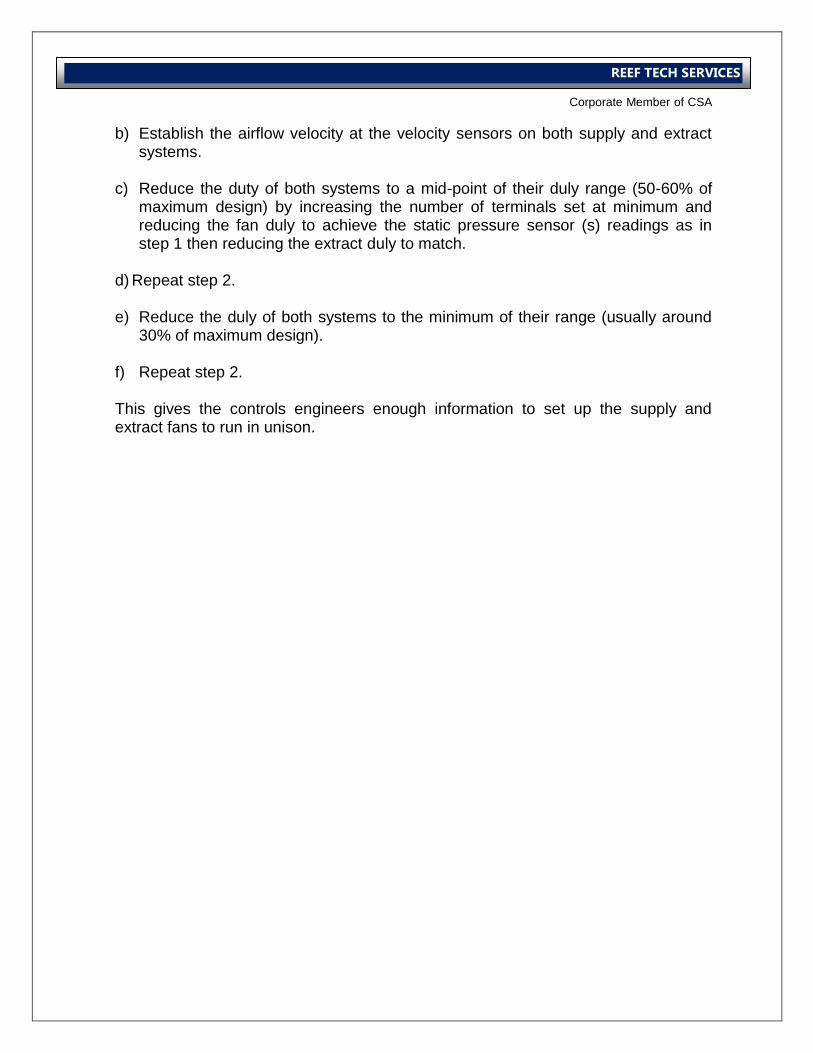
International Operations Business Group
Corporate Member of CSA
REEF TECH SERVICES
b) Establish the airflow velocity at the velocity sensors on both supply and extract systems.
c) Reduce the duty of both systems to a mid-point of their duly range (50-60% of
maximum design) by increasing the number of terminals set at minimum and reducing the fan duly to achieve the static pressure sensor (s) readings as in step 1 then reducing the extract duly to match.
d) Repeat step 2.
e) Reduce the duly of both systems to the minimum of their range (usually around
30% of maximum design).
f) Repeat step 2.
This gives the controls engineers enough information to set up the supply and extract fans to run in unison.
International Operations Business Group
Corporate Member of CSA
REEF TECH SERVICES
Water System Procedure
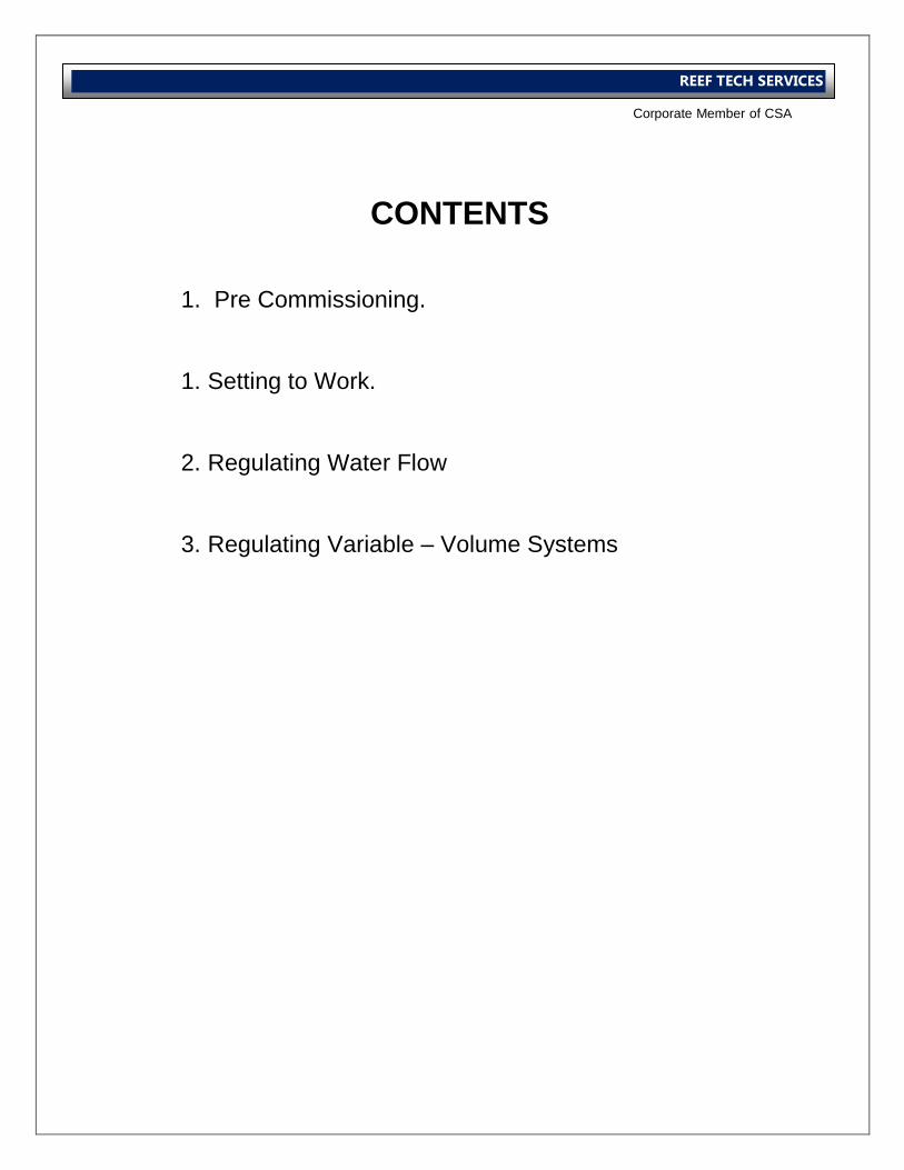
International Operations Business Group
Corporate Member of CSA
REEF TECH SERVICES
CONTENTS
1. Pre Commissioning.
1. Setting to Work.
2. Regulating Water Flow
3. Regulating Variable – Volume Systems
International Operations Business Group
Corporate Member of CSA
REEF TECH SERVICES
WATER SYSTEMS CONSTANT VOLUME
Pre Commissioning A. State of the System 1. General The installer should carry out inspections to ensure that,
a) All plant items are in accordance with the design specification. b) Correct installation procedures have been followed. c) Standards of installation and site cleanliness are acceptable. d) That the installation is fully complete and that all requisite checks have been
undertaken prior to system filling. e) The system cleanliness has been implemented by an adequate flushing and
cleaning process. In the absence of a Code of Practice on flushing, the procedures are recommended in Flushing and Cleaning of Water Systems BSRIA Technical Application Guide 1/89 should provide a guide to standards.
It is vital to the successful completion of the commissioning that the installer should be prepared to issue a cleanliness certificate to the commissioning engineer, if requested. This certificate must include the appropriate documents pertaining to any chemical cleaning. This certificate should be passed to the commissioning engineer before the system is commissioned. 2. Installer Detailed Checks In accordance with CIBSE Code W, the installer should undertake detailed checks to conform to his responsibilities regarding the state of the system. These checks are by requirement, more detailed than those that will subsequently be undertaken by the commissioning engineer, whose checks are made on the assumption of the satisfactory inspection by the installer. The commissioning engineer’s checks, are directly related to the commission-ability of the system and will not establish that the installation is installed to the requirements of the specification. Before Filling Particular checks to be undertaken by the installer should include but not be limited to ensuring that the following have been fulfilled:
a) All equipment and components are installed in accordance with the manufacturer’s instructions for the medium used (e.g. chilled, low, medium or high temperature hot water).
International Operations Business Group
Corporate Member of CSA
REEF TECH SERVICES
b) Pump and valve gland packing and special valve lubricants are compatible with any chemical to be used in the cleaning, flushing and corrosion inhibition of the system.
c) Permanent water connections have been made. d) Flow measurement devices have been installed in accordance with
manufacturers’ instructions. e) Probe pockets, pressure gauges, siphons and test points are installed. f) Manual and automatic air vents are fitted at high points as indicated in the
drawings and specifications, including continuous venting at low velocity sections.
g) Drain Valves and overflows of correct size are fitted. h) Connections to heater and cooler batteries and on the heat exchangers are
made correctly in relation to the design, air and water, flow direction. i) Control, double regulating and non-return valves are installed in accordance
with the flow direction arrows or other indications marked on the devices. j) Relief valves are installed to operate without restriction and in accordance
with manufacturer’s instructions. The outlets are piped away to suitable drain points.
k) Expansion devices are aligned and free from obstruction and are installed and fitted to manufacturer’s instructions including anchor points and rollers etc.
l) Strainers with the mesh, as specified, are installed in an isolated section. Changeover devices for duplex strainers are fitted. (Drain down cocks, are recommended for larger strainers). Access and lifting are adequately provided for.
m) All washers, tanks, nozzles and fittings are inspected for cleanliness. n) All valves and cocks are set in the operational position as given in the valve
schedule (e.g. open, closed). o) The cold feed or mains connection is located correctly. p) All pipe-work and fittings are adequately supported and anchored where
applicable in accordance with the specification. q) All test points are accessible to probes. r) All pipe-work is correctly identified and marked. s) Adequate access is maintained to all manual valve wheels and actuators on
automatically controlled valves. B. System, Filling and Venting (by the installer) Charge the system with water, treated (where specified) to the designers prepared plan. To ensure effective venting, fill slowly from the bottom upwards, thus forcing the air to high points for venting to atmosphere. Careful consideration should be given to the setting of valves and air vents before and during filling, to avoid airlocks and excessive spillage, particularly where the fill is treated. Take care not to exceed the working pressure of the system when filling from a high pressure source.
International Operations Business Group
Corporate Member of CSA
REEF TECH SERVICES
When the whole system is filled, disconnect the filling source, open the permanent supply connection and adjust the feed tank water levels. After static filling and venting the pumps should be operated for a period of about 1 hour and the venting repeated. Complete system venting may take up to a week to achieve. Warning: Do not attempt to fill the system via a pressurization set. It should only be used for final system top up. Frost Precautions: Where work is being carried out in cold weather it is essential that any equipment susceptible to frost damage be protected, by heating the system during working periods. Draining down should be avoided as damp internal surfaces are a primary cause of corrosion. C. Mechanical Checks (by the installer) 1. Pumps When the system is full of water the following should be checked:
a) The external parts of the pump are clean. b) The flow direction is correct. c) All components, bolts, fixings, etc. are secure and no distortion has taken
place on the base in tightening. d) The impeller is free to rotate. e) The level and plumb of pump and motor shaft and slide rails are correct.
Direct drive pumps require particular attention in this respect, with reference of manufacturers’ recommendations.
f) The anti-vibration mountings have correct deflection. g) The correct drive is fitted. h) The pipe-work imposes no strain at the pump connections. i) The pulleys and couplings are secure and their alignment is correct. j) The belts are tensioned and matched. k) Drive guards are securely fitted with proper access for tachometer readings
and belt changes. l) Pressure test points are fitted at both the suction and discharge points of the
pump to facilitate head test to confirm inferred pump performance. 2. Manual / Automatic Control Valves
a) Valve ports are correctly oriented with respect to water flow. b) Valve spindles are free to move. c) Bearing lubrication. d) Rigidity of the mountings. e) Valve stroke, mechanical couplings and linkages for correct geometry.
International Operations Business Group
Corporate Member of CSA
REEF TECH SERVICES
f) Free movement. g) Freedom from excessive lost motion. h) Fit of pins. i) Tightness of locking devices. j) Actuators are fitted to manufacturer’s recommendations with access to
electrical connections. D. Electrical Checks – (by the electrical installation contractor) Before the first operation of any electrical component or appliance the following procedure should be adopted. All requirements of the Health and Safety at Work Act regarding the safety of the engineer and other personnel must be strictly observed. 1. with all electrical supplies Isolated
Checks to ensure that:
a) Appliance and control circuits are locally isolated. b) There are no un-shrouded live components within the panels. c) The panels and switchgear are clean. d) The appliance and surrounding area are clean and dry. e) The transit packing has been removed from contractors and other equipment. f) There is no mechanical damage to switchgear. g) All the connections on bus – bars and wiring are tight. h) All the power and control wiring has been completed in detail in accordance
with the circulate diagram, paying special attention to circuits for star-delta connected or specially wound motors.
i) All fuse ratings are correct. j) All mechanical checks on the pump and motor or valves are complete. k) On site insulation tests on the motor have been performed satisfactorily. l) The internal links on the starter are correct. m) Set starter overload to the motor full load current. n) The adjustable thermal cut-outs are set correctly. o) All electrical water heating appliances are free from damage and all
associated thermostatic controls have a suitable temperature range. p) All the cover plates are replaced.
2. with the Electrical Supply Available
a) Check that the correct provision has been made for local isolation of plant for
both electrical and mechanical safety. b) The declared voltage is available on all supply phases. c) Where motor power ratings are substantial, reduced voltage starting its used,
or if complex interlocks are involved, the control circuit logic and starter operation is tested before the motor is rotated. The supply should first be isolated by withdrawing two power fuses not associated with the control circuit, or by disconnection of cables. The control circuit should be actuated and the starter operation of all contactors, relays and interlocks checked. Finally, open the isolators reinstate the power fuses and close the isolators.
International Operations Business Group
Corporate Member of CSA
REEF TECH SERVICES
d) When small motors have direct on line starting and simple control circuits, the starter operation etc., should be checked when first starting the motor.
e) Never energize valve electrical actuators until mechanical checks have been completed.
Setting to Work A. With System Filled 1. Checks – Mechanical
a) All normally open valves are fully open. b) All bypass and normally closed valves are closed. c) All thermostatically controlled valve are fully open and will not be affected by
ambient air or water temperature during the test period. d) A method of operating electrically controlled valve is available and that these
are set to normal operation mode. e) A method of operating pneumatically controlled valve is available and these
are set to normal operating mode. The pump suction or return valve is fully open.
f) The delivery valve only is closed on the standby pump unless non-return valves are fitted: the suction valve should be left open. (it is bad practice to leave any vessels full of water and completely isolated, as a temperature rise could cause an excessive pressure build up)
g) Pump casing is vented of air. h) The discharge or flow valve from the pump is closed by, say, 50% to limit the
initial start current. B. Initial Run
1. Checks on Activating the Motor Starter:
a) The direction and speed of rotation of the motor shaft are correct. b) The motor, pump and drive are free from vibration and undue noise. c) For star-delta starters the starter sequence timing has been adjusted if (by
the electrical installer). d) The motor running current is balanced between phases. e) There is no overheating of the motor. f) On multi-speed motors, motor running currents are correct. g) The ventilation systems of air cooled motors are unimpeded.
2. First System Checks a) Avoid starting the motor repeatedly. (This prevents over stressing the fuses,
switchgear and motor).
International Operations Business Group
Corporate Member of CSA
REEF TECH SERVICES
b) Open the discharge valve gradually until the motor current reaches either the design value or the motor full load current, whichever is the lower.
c) Check the pump pressure developed, using the pump pressure gauges, against the system designed working pressure. (Where excessive pressure is developed at this stage, the pump should be shutdown and the cause should be investigated).
C. Running–in Period The pumps must be ‘run in’ in accordance with the manufacturers’ instructions. Do not leave pump unattended or allow them to run outside working hours. 1. Check that:
a) All bearings and motor temperatures remain within manufacturer’s specification.
b) After four hours running all strainers are inspected and cleaned. If they are excessively dirty then continue frequent inspection and cleaning.
D. Standby Pump The standby pump should be commissioned as above. E. Secondary Pump The secondary system (if any) should be isolated and the primary with system pressurization provided (where necessary) should be applied to assist in removing air from the system. Regulating Water Flow – Constant Volume System Basis of Balancing
Proportional balancing is used for constant volume system and the maximum flow method for variable volume systems without diversity. However, heat-balancing methods are sometimes necessary in final branch or terminal distribution. These involve temperature measurements. Warning Balancing a system requires the insertion of manometers with probes into pressure test points. In a charged system the water temperature must be below 60 Deg C when this is done. Under no circumstances must a MTHW or HTHW system be commissioned at operating temperature as serious injury may result. Any pressure or temperature measuring point must be preceded by a manually operated separate isolating device.
International Operations Business Group
Corporate Member of CSA
REEF TECH SERVICES
A. Preliminary Checks 1. Pump Shut Off Head Test To verify the operational performance of a pump it is necessary to check the measured performance against type test data provided by the manufacturer.
a) Connect a suitable differential pressure gauge across the suction and discharge pressure test points of the pump.
b) With the pump running, slowly close the discharge valve. Do not run in this condition for longer than 15 minutes or the time taken for the pump to overheat.
c) Determine the shut off head and check against the manufacturers’ data for zero flow.
d) Where the test results coincides with the manufacturers types test data proceed to (e). Where this is not the case, draw a curve parallel to that produced from the published data starting at the shut-off head pressure.
e) Open the discharge valve slowly to the full open position. f) Record the total head with the differential pressure gauge at full flow rate and
read the actual flow from the manufacturers data, or from corrected graph curve as appropriate.
g) If performance is inadequate refer to the installation contractor and designer. 2. Preliminary Flow Rate Check With all the valves fully open, measure and record the total actual flow rate and compare this with the total system design flow requirement. Where necessary, close the main regulation valve to provide a flow of approximately 110% design. B. Balancing The system is balanced on the basis of the ratio of actual flow rate to design flow rate. In any one branch the emitter units are regulated to the same proportion as the index (least favored) in that branch. Like wise, each branch on one riser and each riser on one header. This is achieved by measuring the pressure differential across flow measuring equipment and regulating the flow to design flow requirements by regulating valves. Repeated balancing may be required to bring actual flow rates within design tolerances. 1. Identification of least favored (index) and most favored circuits
a) Open all line circuit valves and close all bypass valves. b) Set automatic control valves manually to full circuit flow. c) Start pump (s) d) Using schematic drawing, measure flow rate and pressure differential at each
measuring station with manometer and record results. Check against design valves.
International Operations Business Group
Corporate Member of CSA
REEF TECH SERVICES
e) For each measuring station evaluate the percentage design flow rate DFR (%) = 100 fa/fd, where fa is the actual and fd the design flow rate.
f) Make certain that the primary flow measuring station at the pump is indicating DFR (%) = 100 – 110%. This ensures that there is enough flow to commission the system to the designer’s requirement within the set tolerance.
g) Starting at the pump, identify on the mains (headers, risers, etc.), that part of the system which is receiving the highest flow rate in terms of DFR (%). This will be the most favored circuit.
h) List the branches in descending order of DFR (%). That with the lowest is the least favored (index) circuit.
i) Balancing consists in the progressive closure of regulating valves starting with the most favored branch in the most favored circuit.
2. Balancing terminals, branches, risers, and headers by proportional flow
a) If DFR (%) for a branch is above 150% reduce the branch flow rate to give DFR (%) – 100%.
b) Double regulating valves should preferably not be set less than 25% open 75% closed.
c) Identify the least favored terminal, i.e. that with the lowest DFR (%).This is defined as the branch index terminal. In a typical distribution system this will be the last measuring point on the branch. If it is not, reduce the flow to the most remote terminal until f % is equal to that of the index terminal within the specified tolerance.
d) Adjust the regulating valve for the next terminal nearer the pump so that the DFR (%) values for this terminal and the most remote terminal are equal within the specified tolerance. Record the instruments readings, DFR (%) and valve settings for both terminals and lock the double regulating valves in their set positions.
e) Continue by adjusting the regulating valve for the next terminal nearer the pump until DFR (%) for this terminal is equal, within the specified tolerance, to that for either of the two terminals balanced in stage (d). This value will probably have altered from that recorded at stage (d) so it is essential to re measure the flow for every comparison of DFR (%) values. Record instrument readings, DFR (%) values and valve settings for both terminals.
f) Continue balancing the upstream as in stage (e) using the same reference terminal for comparison of the DFR (%) values until all terminals are balanced.
g) If it is found that the regulating valve for the index terminal has to be adjusted to achieve balance this indicates that the regulating valve on the most remote terminal was closed too far at stage ( c). In this case open the regulating valve for the next index terminal return to stage ( c), and follow the procedure through again.
h) Proceed to the next most favored branch on the riser and carry out terminal balancing as in stages (a) to (h).
i) For the complete riser each branch terminal is now in balance with the other terminals on the same branch. Branches now have to be balanced.
International Operations Business Group
Corporate Member of CSA
REEF TECH SERVICES
j) The procedure for balancing branches on a riser is identical to that for balancing terminals on a branch.
k) When several risers are fed from a header the same procedure should be used to balance the risers.
l) At this stage each riser, branch and header are proportionately balanced within the specified tolerances. Flow rates throughout the whole system will now retain the same proportional relationship for any setting of the main regulating valve.
m) Adjust the main regulating valve, to bring the total flow to the design flow within the specified tolerance. Record the instrument reading, the flow rate and the valve or speed setting and lock the valve or speed setting.
n) Check a sample of terminal, branch and riser flow rates as specified. o) Report to the designer any double regulating valves, which are less than 25
% open. p) Lock all the double regulating valves in the regulated position.
3. Secondary regulation of bypass circuit
a) On a straightforward bypass the regulating valve is brought into operation by opening the control valve to the by-pass operation.
b) The by-pass regulation valves should be adjusted to give the same flow rate through the bye-pass as the flow rate through the main bypassed circuit.
4. Secondary and Primary final regulation including injection circuits
a) In designs incorporating secondary pump systems including injection circuitry, the secondary circuits must be balanced with the primary circuit in operation but isolated from the secondary circuit.
b) With the secondary automatic control mixing three way valve in the full flow position, measure the primary flow rate and calculate the DFR (%) as in the secondary system.
c) Operate the secondary automatic control three-way mixing valve to the bypass position and regulate the bypass valve to give the same DFR (%) as in the secondary system.
Regulating Variable – Volume Systems Variable – volume systems fall into two categories. Small systems typically have thermostatic radiator valves and excess differential pressure relief valves. Large systems have zone differential pressure regulators and sometimes, variable speed pumping. The system is balanced on the basis of proportionality to ensure that under full design load, the correct mass flow rate occurs in each branch, riser and header. Balance of a variable – volume system requires the use of automatic flow control valves, operated by differential pressure, in each principal branch. Downstream of
International Operations Business Group
Corporate Member of CSA
REEF TECH SERVICES
the flow control valve proportional balancing is still required on all sub-circuits. An approximate balance can be inherent in the system design, e.g. in reverse return systems. Note: Suitable isolated pressure tappings should be located at the measuring positions for differential pressure control. This will enable the operation of the controller to be minimized. A. Small System These systems often have conventional thermostatic valves and flow – to – return differential pressure relief valves to ensure minimum flow. They are most conveniently balanced manually at low flow temperature by regulating to achieve approximately equal return connection temperatures. Thermostatic valves will automatically balanced at all part load conditions. It is important that the design ensures in minimum load (all thermostatic valves closed) the pump head does not exceed the maximum closing pressure of thermostatic valves. B. Larger Single Building Systems These are fitted with automatic differential pressure regulators (DPR) on sub – systems serving groups of terminals. DPR automatically balance the main pipe distribution upstream. 1. Differential Pressure Regulation
a) The DPR must be set correctly at the design pressure differential across the branch they serve.
b) The operation of each DPR must be checked and documented to ensure that it controls the differential pressure at low and high flow rates and with high and low upstream pressure differentials.
2. Sub – systems downstream of differential pressure regulators.
Each sub - system controlled by a differential pressure regulator required the
following commissioning procedure:
a) The correct operation of two-port control valves must be tested and recorded, under normal operation with all terminal control valves wide open.
b) Check and record the differential pressure across the sub-system. If this is below the design value due to system diversity it must be restored by temporarily valving off other sub-systems as necessary.
c) With the sub-circuit operating at its design differential pressure, measure and record the pressure drop across the index terminal and its control valve.
d) Measure and record the sub-circuit flow. Note that this may be higher than the design value if this was based on diversity, but the flow should not be throttled back to design value.
International Operations Business Group
Corporate Member of CSA
REEF TECH SERVICES
e) After dealing with all differential pressure regulated sub-circuits, any temporarily valve off to compensate for diversity should be recorded.
3. Main Pump Flow
The pump flow and operating head should be measured, recorded and plotted on the pump curve; note that these will differ from the pump design flow head for 100% load. The motor current and no-flow head should be recorded.
Note: This type of variable flow system is designed on the basis of diversity caused by the sum of all the terminal flows with control valves wide open, considerably exceeding, the total flow required to meet the maximum design load of the system. It is therefore not practicable to demonstrate the design flow and distribution without the design thermal load on the system. C. Regulation by temperature balance Where a system or part of a system consists of a number or relatively small terminal units, e.g. radiators, convectors, it will often be physically possible or economic to install a flow measuring device at every terminal unit. The technique of proportional balancing must therefore be adapted to the particular system. 1. Limitations The temperature balance method should be confined to low temperature hot water heating and chilled waters system, where an equal temperature difference is required through each terminal unit. 2. Procedure
a) Operate the system at a moderate flow temperature. This will be governed to some extent by the ambient temperature, but a minimum of 60C should be aimed for.
b) If the system is controlled by an outside compensator this should be adjusted to ensure that a constant flow temperature is maintained during the heat balance commissioning.
c) Regulate each terminal unit return valve until all returns register at equal temperature to the palm of the hand or by a contact thermometer.
General
When using the heat balance method a procedure similar to that recommended for balancing terminals fitted with flow measuring devices should be adopted, that is, regulate from the index back towards the pump. The heat balance and regulation on the terminals on any branch should be completed before the final regulation and flow measurement on that branch.
International Operations Business Group
Corporate Member of CSA
REEF TECH SERVICES
Note: This method is an approximation and will not achieve any significant level of accuracy. It is not appropriate to attempt to achieve a higher degree of accuracy, by use of accurate temperature measuring instruments. If accuracy is required the design must incorporate flow-measuring devices.
D. Flow rate measurement tolerances The tolerances as generally applied by the Company are set out in appendix B. These are those recommended in BSRIA Application Guide 1/79 Table V. In our experience these are appropriate for normal commissioning practice and should provide satisfactory system performance. The achievement of smaller tolerances would not have significant practical advantage, and is however achievable within the constraints of operating conditions.
International Operations Business Group
Corporate Member of CSA
REEF TECH SERVICES
Acoustic Test Procedure
International Operations Business Group
Corporate Member of CSA
REEF TECH SERVICES
CONTENTS
1. Introduction.
2. Specification for Acoustic Test Equipment.
3. Measurement of System’s Noise in Internal Areas.
4. Penetration in Building Fabric.
5. Recommended NC Levels for Various Environments.
(Group A)
6. Recommended NR Levels for Various Environments.
(Group B)
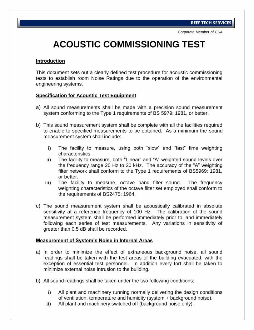
International Operations Business Group
Corporate Member of CSA
REEF TECH SERVICES
ACOUSTIC COMMISSIONING TEST
Introduction
This document sets out a clearly defined test procedure for acoustic commissioning tests to establish room Noise Ratings due to the operation of the environmental engineering systems. Specification for Acoustic Test Equipment
a) All sound measurements shall be made with a precision sound measurement system conforming to the Type 1 requirements of BS 5979: 1981, or better.
b) This sound measurement system shall be complete with all the facilities required to enable to specified measurements to be obtained. As a minimum the sound measurement system shall include:
i) The facility to measure, using both “slow” and “fast” time weighting
characteristics. ii) The facility to measure, both “Linear” and “A” weighted sound levels over
the frequency range 20 Hz to 20 kHz. The accuracy of the “A” weighting filter network shall conform to the Type 1 requirements of BS5969: 1981, or better.
iii) The facility to measure, octave band filter sound. The frequency weighting characteristics of the octave filter set employed shall conform to the requirements of BS2475: 1964.
c) The sound measurement system shall be acoustically calibrated in absolute sensitivity at a reference frequency of 100 Hz. The calibration of the sound measurement system shall be performed immediately prior to, and immediately following each series of test measurements. Any variations in sensitivity of greater than 0.5 dB shall be recorded.
Measurement of System’s Noise in Internal Areas a) In order to minimize the effect of extraneous background noise, all sound
readings shall be taken with the test areas of the building evacuated, with the exception of essential test personnel. In addition every fort shall be taken to minimize external noise intrusion to the building.
b) All sound readings shall be taken under the two following conditions:
i) All plant and machinery running normally delivering the design conditions of ventilation, temperature and humidity (system + background noise).
ii) All plant and machinery switched off (background noise only).
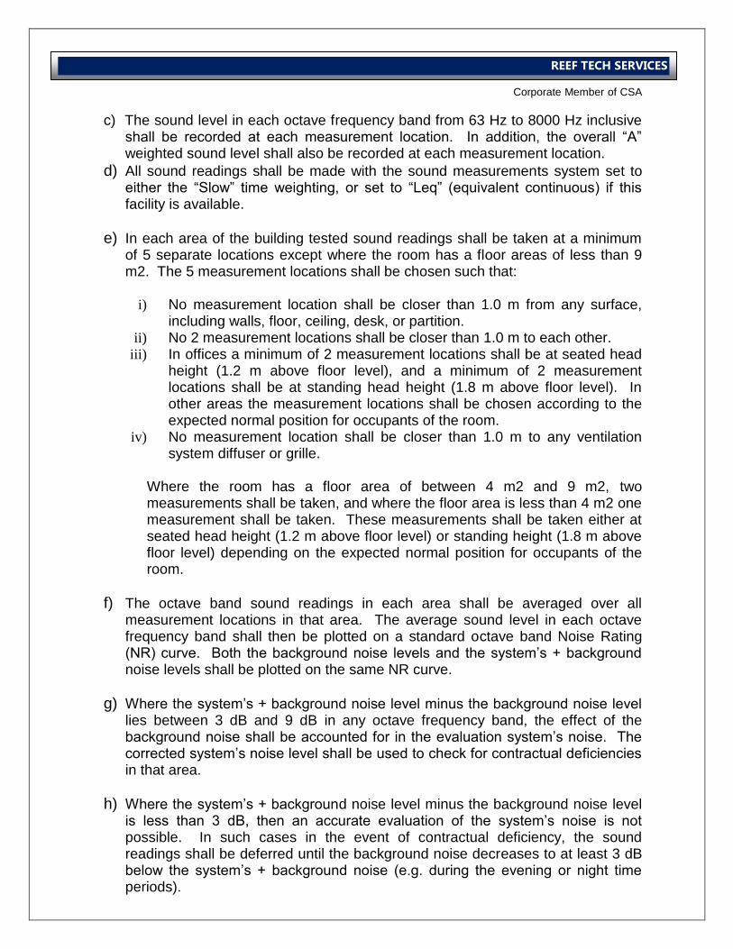
International Operations Business Group
Corporate Member of CSA
REEF TECH SERVICES
c) The sound level in each octave frequency band from 63 Hz to 8000 Hz inclusive shall be recorded at each measurement location. In addition, the overall “A” weighted sound level shall also be recorded at each measurement location.
d) All sound readings shall be made with the sound measurements system set to either the “Slow” time weighting, or set to “Leq” (equivalent continuous) if this facility is available.
e) In each area of the building tested sound readings shall be taken at a minimum of 5 separate locations except where the room has a floor areas of less than 9 m2. The 5 measurement locations shall be chosen such that:
i) No measurement location shall be closer than 1.0 m from any surface,
including walls, floor, ceiling, desk, or partition. ii) No 2 measurement locations shall be closer than 1.0 m to each other.
iii) In offices a minimum of 2 measurement locations shall be at seated head height (1.2 m above floor level), and a minimum of 2 measurement locations shall be at standing head height (1.8 m above floor level). In other areas the measurement locations shall be chosen according to the expected normal position for occupants of the room.
iv) No measurement location shall be closer than 1.0 m to any ventilation system diffuser or grille.
Where the room has a floor area of between 4 m2 and 9 m2, two measurements shall be taken, and where the floor area is less than 4 m2 one measurement shall be taken. These measurements shall be taken either at seated head height (1.2 m above floor level) or standing height (1.8 m above floor level) depending on the expected normal position for occupants of the room.
f) The octave band sound readings in each area shall be averaged over all measurement locations in that area. The average sound level in each octave frequency band shall then be plotted on a standard octave band Noise Rating (NR) curve. Both the background noise levels and the system’s + background noise levels shall be plotted on the same NR curve.
g) Where the system’s + background noise level minus the background noise level lies between 3 dB and 9 dB in any octave frequency band, the effect of the background noise shall be accounted for in the evaluation system’s noise. The corrected system’s noise level shall be used to check for contractual deficiencies in that area.
h) Where the system’s + background noise level minus the background noise level is less than 3 dB, then an accurate evaluation of the system’s noise is not possible. In such cases in the event of contractual deficiency, the sound readings shall be deferred until the background noise decreases to at least 3 dB below the system’s + background noise (e.g. during the evening or night time periods).
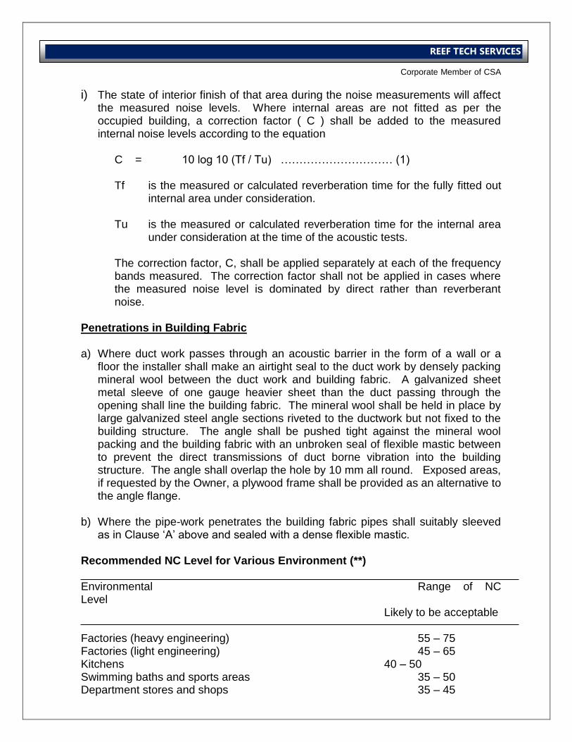
International Operations Business Group
Corporate Member of CSA
REEF TECH SERVICES
i) The state of interior finish of that area during the noise measurements will affect the measured noise levels. Where internal areas are not fitted as per the occupied building, a correction factor ( C ) shall be added to the measured internal noise levels according to the equation
C = 10 log 10 (Tf / Tu) ………………………… (1) Tf is the measured or calculated reverberation time for the fully fitted out
internal area under consideration. Tu is the measured or calculated reverberation time for the internal area
under consideration at the time of the acoustic tests. The correction factor, C, shall be applied separately at each of the frequency bands measured. The correction factor shall not be applied in cases where the measured noise level is dominated by direct rather than reverberant noise.
Penetrations in Building Fabric
a) Where duct work passes through an acoustic barrier in the form of a wall or a floor the installer shall make an airtight seal to the duct work by densely packing mineral wool between the duct work and building fabric. A galvanized sheet metal sleeve of one gauge heavier sheet than the duct passing through the opening shall line the building fabric. The mineral wool shall be held in place by large galvanized steel angle sections riveted to the ductwork but not fixed to the building structure. The angle shall be pushed tight against the mineral wool packing and the building fabric with an unbroken seal of flexible mastic between to prevent the direct transmissions of duct borne vibration into the building structure. The angle shall overlap the hole by 10 mm all round. Exposed areas, if requested by the Owner, a plywood frame shall be provided as an alternative to the angle flange.
b) Where the pipe-work penetrates the building fabric pipes shall suitably sleeved
as in Clause ‘A’ above and sealed with a dense flexible mastic. Recommended NC Level for Various Environment (**) Environmental Range of NC Level Likely to be acceptable Factories (heavy engineering) 55 – 75 Factories (light engineering) 45 – 65 Kitchens 40 – 50 Swimming baths and sports areas 35 – 50 Department stores and shops 35 – 45
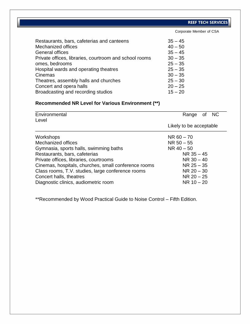
International Operations Business Group
Corporate Member of CSA
REEF TECH SERVICES
Restaurants, bars, cafeterias and canteens 35 – 45 Mechanized offices 40 – 50 General offices 35 – 45 Private offices, libraries, courtroom and school rooms 30 – 35 omes, bedrooms 25 – 35 Hospital wards and operating theatres 25 – 35 Cinemas 30 – 35 Theatres, assembly halls and churches 25 – 30 Concert and opera halls 20 – 25 Broadcasting and recording studios 15 – 20 Recommended NR Level for Various Environment (**) Environmental Range of NC Level Likely to be acceptable Workshops NR 60 – 70 Mechanized offices NR 50 – 55 Gymnasia, sports halls, swimming baths NR 40 – 50 Restaurants, bars, cafeterias NR 35 – 45 Private offices, libraries, courtrooms NR 30 – 40 Cinemas, hospitals, churches, small conference rooms NR 25 – 35 Class rooms, T.V. studies, large conference rooms NR 20 – 30 Concert halls, theatres NR 20 – 25 Diagnostic clinics, audiometric room NR 10 – 20 **Recommended by Wood Practical Guide to Noise Control – Fifth Edition.

International Operations Business Group
Corporate Member of CSA
REEF TECH SERVICES
Electrical Power System
Acceptance Test Procedure
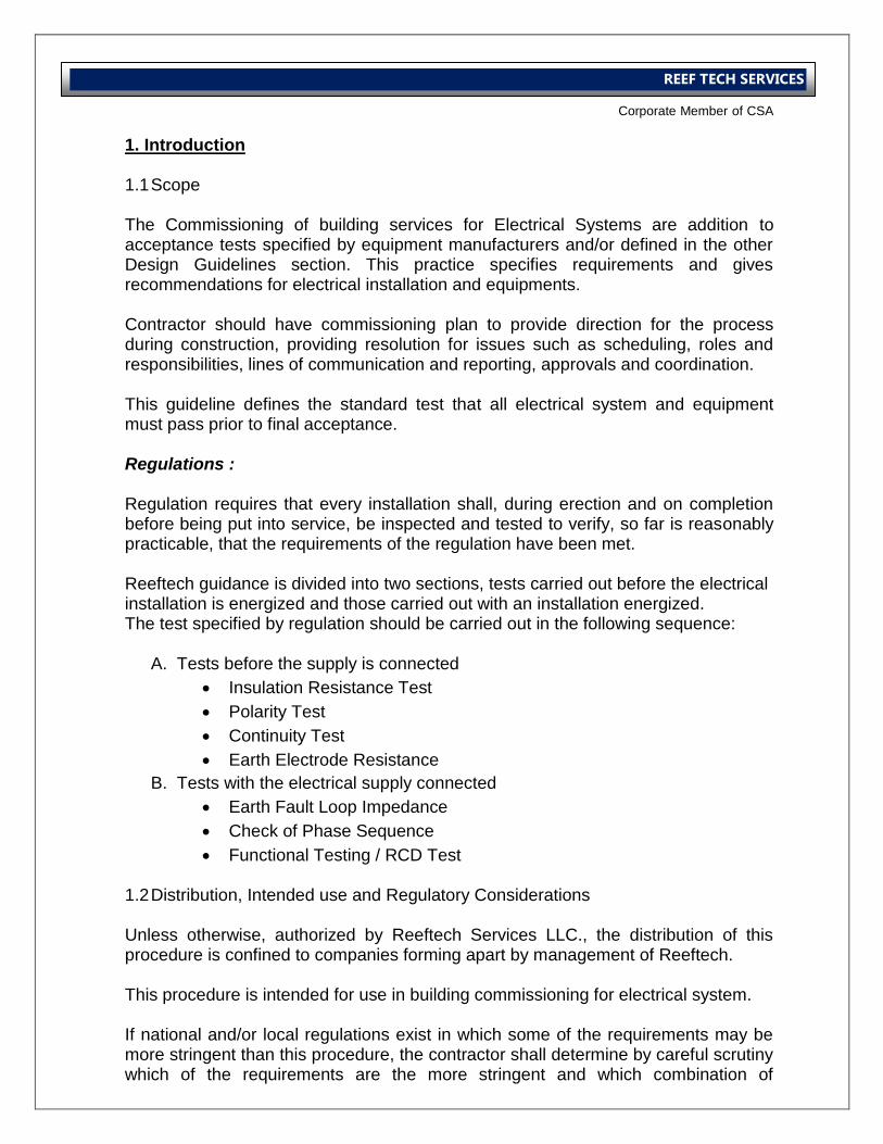
International Operations Business Group
Corporate Member of CSA
REEF TECH SERVICES
1. Introduction 1.1 Scope
The Commissioning of building services for Electrical Systems are addition to acceptance tests specified by equipment manufacturers and/or defined in the other Design Guidelines section. This practice specifies requirements and gives recommendations for electrical installation and equipments. Contractor should have commissioning plan to provide direction for the process during construction, providing resolution for issues such as scheduling, roles and responsibilities, lines of communication and reporting, approvals and coordination. This guideline defines the standard test that all electrical system and equipment must pass prior to final acceptance. Regulations : Regulation requires that every installation shall, during erection and on completion before being put into service, be inspected and tested to verify, so far is reasonably practicable, that the requirements of the regulation have been met. Reeftech guidance is divided into two sections, tests carried out before the electrical installation is energized and those carried out with an installation energized. The test specified by regulation should be carried out in the following sequence:
A. Tests before the supply is connected
Insulation Resistance Test
Polarity Test
Continuity Test
Earth Electrode Resistance
B. Tests with the electrical supply connected
Earth Fault Loop Impedance
Check of Phase Sequence
Functional Testing / RCD Test 1.2 Distribution, Intended use and Regulatory Considerations
Unless otherwise, authorized by Reeftech Services LLC., the distribution of this procedure is confined to companies forming apart by management of Reeftech. This procedure is intended for use in building commissioning for electrical system. If national and/or local regulations exist in which some of the requirements may be more stringent than this procedure, the contractor shall determine by careful scrutiny which of the requirements are the more stringent and which combination of
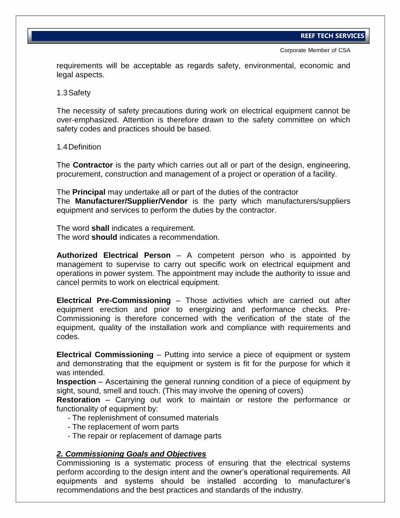
International Operations Business Group
Corporate Member of CSA
REEF TECH SERVICES
requirements will be acceptable as regards safety, environmental, economic and legal aspects. 1.3 Safety
The necessity of safety precautions during work on electrical equipment cannot be over-emphasized. Attention is therefore drawn to the safety committee on which safety codes and practices should be based. 1.4 Definition
The Contractor is the party which carries out all or part of the design, engineering, procurement, construction and management of a project or operation of a facility. The Principal may undertake all or part of the duties of the contractor The Manufacturer/Supplier/Vendor is the party which manufacturers/suppliers equipment and services to perform the duties by the contractor. The word shall indicates a requirement. The word should indicates a recommendation. Authorized Electrical Person – A competent person who is appointed by management to supervise to carry out specific work on electrical equipment and operations in power system. The appointment may include the authority to issue and cancel permits to work on electrical equipment. Electrical Pre-Commissioning – Those activities which are carried out after equipment erection and prior to energizing and performance checks. Pre-Commissioning is therefore concerned with the verification of the state of the equipment, quality of the installation work and compliance with requirements and codes. Electrical Commissioning – Putting into service a piece of equipment or system and demonstrating that the equipment or system is fit for the purpose for which it was intended. Inspection – Ascertaining the general running condition of a piece of equipment by sight, sound, smell and touch. (This may involve the opening of covers) Restoration – Carrying out work to maintain or restore the performance or functionality of equipment by: - The replenishment of consumed materials - The replacement of worn parts - The repair or replacement of damage parts 2. Commissioning Goals and Objectives Commissioning is a systematic process of ensuring that the electrical systems perform according to the design intent and the owner’s operational requirements. All equipments and systems should be installed according to manufacturer’s recommendations and the best practices and standards of the industry.
International Operations Business Group
Corporate Member of CSA
REEF TECH SERVICES
Commissioning will include documenting the design intent, followed by activities in the construction, acceptance and warranty phases of the project. The participation of the contractors in commissioning activities will follow the requirements defined in the specification. 2.1 Objectives - Document that equipment is installed and started as per standard - Document system performance with thorough functional performance testing and monitoring - Ensure that the operating personnel are adequately trained on the operation of the equipment - To verify proper functioning of the equipment / system after installation - To capture and record performance data of the whole installation as the baseline for future operation and maintenance 3. Procedures, Responsibility and Documentations 3.1 Procedure and Responsibilities Electrical installations and equipment engineered and/or erected by contractors and in general, any equipment which has been completed and is ready for operation, shall be subject to certain take-over procedures which shall have been agreed between the contractor and the principal well before the pre-commissioning stage. Furthermore, take-over procedure should state clearly the relevant responsibilities of contractor and principal. The organization and execution of Pre-Commissioning and Commissioning activities shall be the responsibility of contractor and/or commissioning management party. Unless otherwise agreed by the principal, complex electrical systems (e.g. HV/LH Switchgear, Generators, AVR’s, VSDS’s, UPS’s) shall be commissioned with the assistance of manufacturer. The steps required to connect an electrical system, prior to its initial energizing, to an existing electrical network, shall be jointly agreed by the authorized electrical person responsible for each electrical network. Where site conditions prevent full performance tests (e.g. Power Output, Temperature Rise), agreement should be reached between the principal and contractor on the need for such tests at a later date. If applicable, the principal should have internal procedure for equipment acceptance by engineering/construction department.
International Operations Business Group
Corporate Member of CSA
REEF TECH SERVICES
3.2 Documents The contractor and/or commissioning management party shall complete the inspection form from pre-commissioning and commissioning. Form is applicable to all equipment; subsequent forms shall be used as required. The contractor shall develop additional inspection forms for equipment not covered or not fully covered by commissioning management party. All deviations from requirements shall be documented on an exemption list which shall be presented to those responsible for the installation work for their agreement and action. 4. Testing Criteria and Commissioning Methods 4.1 Testing Criteria High potential tests shall perform at the AC or DC voltage unless specified otherwise herein. Performing more than one high potential test on any item shall authorized by the owner, contractor/consultant and/or principal. Dielectric absorption tests shall be performed with a 2,500 volt DC megger. Megger tests shall be performed at a DC voltage of 1,000 volts for 600 volts rated equipment, and at a DC voltage of 500 volts for 120-300 volt rated equipment. Continuity check shall be performed with a low DC meter, light or bell. The resistance to ground shall be measured using either the three point method or the fall-off potential method. Test instruments shall be calibrated to national standards to ensure the accuracy of tests. These calibration reports shall be made available when requested. Depending upon frequency of use, the instruments shall be calibrated at least every 12 months. 4.2 Visual Inspection Prior to manual operation and electrical testing, following needs to verify: - The equipment complies with the contract documents and the shop drawing submittal - The equipment is completely and properly installed according to the contract documents and the manufacturer’s instructions. - Adequate working space exists around the equipment to fully open doors and access panels, and to access all components that require for testing. - The equipment is free from damage and defects - Shipping blocks and restraints have been removed.
International Operations Business Group
Corporate Member of CSA
REEF TECH SERVICES
- The equipment has been aligned and lubricated if required - The ventilation louvers are open and unobstructed - Electrical connections have been tightened - Voltages, Phases and rotation have been identified - Terminations have been identified - Equipment labels have been installed - The equipment is ready to be electrically testing and commissioning 4.3 Insulation Testing Insulation test shall be carried out prior to the energizing of equipment and cable. The following 2 methods shall be used: - Insulation Resistance (IR) testing for motors, generators, transformers, LV Switchgear and all equipment other than those items susceptible to damage by over-voltage (e.g. Electronic Components) - High Voltage ac or dc testing for HV Switchgear and HV Cable 4.3.1 Insulation Resistance (IR) Test IR Testing shall be carried out by applying a dc voltage from an insulation tester at voltage level. For correct comparative interpretation of test data, Subsequent IR test should be carried out at the same voltage level as the initial test. The measured resistance value is also dependent on the temperature of the insulation. As a guide, the IR or windings reduces by approximately 50% for each 10°C rise in temperature. 4.3.2 High Voltage Test Before high-voltage test is executed, insulation resistance test shall be carried out. High Voltage test can be carried out by applying ac (power frequency), very low frequency (VLF), or dc voltage at a level above the operating voltage. There are distinct differences in the nature and practicality of this test. Whilst testing at power frequency is preferable, the ac test equipment must be capable of supplying the capacitive current requirement of the item under test. Thus physically large test equipment is frequently called for which is impractical for field commissioning use. For on-site commissioning, dc test equipment may be used.
International Operations Business Group
Corporate Member of CSA
REEF TECH SERVICES
High Voltage testing of electrical equipment, except LV cables, shall have been carried out at the Manufacturer’s work with ac at voltage levels in accordance with the relevant procedures or international standards. Repeated high voltage pressure test may introduce weak points in the insulation of windings, and therefore such tests shall not be applied at site to generators, motors and transformers. If, however, for special reasons these test are consider to be necessary, they shall be carried out only after consultation with the manufacturer. 4.4 Conductivity and Earth Resistance Test 4.4.1 Conductivity Test Conductivity test shall be carried out on Switchgear busbar connections and switchgear earth system joints in order to establish their tightness and condition. Conductivity testing shall be carried out with a low resistance test (e.g Ducter with a 20 A dc output) For identical connections the measured values shall not differ by more than 20% from each other. 4.4.2 Earth Resistance Test Confusing standards and conflicting opinions have plagued the field of grounding. One of the most important, but least understood considerations in designing and maintaining electrical systems is the grounding of all components. Low resistance earth grounding is essential for safety and protection. It is the basis for any facilities power quality assurance program. Effective earth grounding is essential for grounded ac and dc electrical equipment and distribution systems. Earth resistance test shall be carried out a regular program of testing to ensure effective grounding provides the level of safety required to protect personnel and equipment from shock and fire hazard. 4.5 Wiring and Terminal Checks Electrical wiring shall be check against the schematic diagrams. Factory tested assemblies such as switchgear should be require only sample checks. 4.6 Functional Test Functional test shall be carried out to demonstrate the correct operation of complete systems. Particular attention should be paid to equipment interfaces, where there is a greater likelihood of functional impairment.
International Operations Business Group
Corporate Member of CSA
REEF TECH SERVICES
In cases where complicated control and/or interlock systems are used, the contractor/consultant shall demonstrate compliance with the design requirements by using special case by case functional checklist and system logic diagrams. 5. Testing and Commissioning Procedures 5.1 Medium Voltage Primary Cables A continuity test, a 2,500 volt DC megger test, a DC High potential test, and a second 2,500 volt DC megger test shall be performed on 15kV primary cables after the cables have been spliced or terminated. The high potential test shall be performed at 45 kV on new cable installations and at 30 kV on existing installations or when new cable has been spliced to existing cable. 5.2 600 Volt Power Cables A continuity check and a 1,000 volt DC megger test shall be performed on 600 volt power cables and larger. The megger test shall be performed between each pair of conductors and from each conductor to ground. Each test shall be performed for 15 seconds or until the insulation resistance value stabilizes. The insulation resistance between conductors and from each conductor to ground shall be 100 MΩ minimum in 1 minute or less. In addition, the lowest insulation resistance value shall not differ from the highest value by more than 20%. If all megger readings for a given circuit are above 1000 MΩ, the 20% balance requirement may be waived. 5.3 Control Cables A continuity check shall be performed on control and instrumentation wiring. 5.4 Substation Primary Switches A continuity check, a 2,500 volt DC megger test and a 37 kV DC high potential test shall be performed on primary switches. 5.5 Substation Transformers A DC megger test and a turns ration test shall be performed on unit substation transformers. The DC megger test shall be performed at 2,500 volts on coils rated over 600 volts, and at 1,000 volts on coils rated 600 volts and below. 5.6 Substation Secondary Switchgear A continuity check and a 1,000 volt DC megger test shall be performed on the buses and on the main, tie and feeder breakers.
International Operations Business Group
Corporate Member of CSA
REEF TECH SERVICES
A Ducter (contact resistance) test shall be performed on main, tie and feeder breakers in unit substation. Maximum readings shall not exceed manufacturer limits. The over-current devices of substation breakers with electronic trip units shall be tested using the primary current injection method. Secondary current injection shall not be used. Molded case circuit breakers with thermal/magnet trips shall not be primary current injection tested. A 1,000 volt DC megger test and a turns ratio test shall be performed on CT’s and PT’s. The kWh meter shall be calibrated. 5.7 Engine-Generators and Automatic Transfer Switches A continuity check and a 1,000 volt DC megger test shall be performed on the generator windings, generator circuit breaker, power circuit portions of the automatic transfer switches and the inter-connecting power circuit wiring. A continuity check shall be performed on the control wiring. The metering and time relays shall be calibrated and tested. The manufacturer’s recommended normal start-up testing shall be performed. A load bank test shall be performed on the generator with a load bank rated at 100% of full generator output for a period of at least 120 minutes. If the engine is natural gas and complaint capable rather than certified as defined in EPA NSPS emission standards, an EPA (Environmental Protection Agency) Initial Performance Test shall be performed. This test shall consist of 3 separate tests 1 hour runs at close to full load. It shall be performed in accordance with EPA test requirements and the measured emissions shall be within EPA limits. Normal power shall be shut off to each automatic transfer switch, 1 at a time. Each time the engine-generator shall start and the automatic transfer switch shall function according to the design intent. Normal power shall be return to the automatic transfer switch. The automatic transfer switch shall return to normal power and the engine-generator shall shut down according to the design intent. Normal power shall be shut off to the entire building. The engine-generator shall start and the automatic switches shall function according to the design intent. Normal power shall be return. The automatic transfer switches shall return to normal power and the engine generator will shut down according to the design intent. The generator shall be tested for voltage and frequency stability. The automatic transfer switch shall be used to apply load to the generator according to the worst case step loading sequence defined in the generator specification. The generator voltage and frequency shall remain within the values listed in generator specification.
International Operations Business Group
Corporate Member of CSA
REEF TECH SERVICES
The ATS maintenance by-pass switches shall be inspected for proper labeling and tested for proper operation in all modes. The generator and automatic transfer switch controls, gauges, status indicators and alarms including remote annunciator shall be tested for proper operation. 5.8 Transformers, Reactors, Switchboards, Panel boards and Motor Control Equipment A continuity check and a 1,000 volt DC megger test shall be performed on distribution and isolation transformers and on line reactors. A 1,000 volt DC megger test shall be performed on buses, motor starters, circuit breakers and dis-connect switches. This test maybe combined with the power cable megger test by testing the devices and terminated cables together. A continuity check shall be performed on motor control circuits and control panel internal wiring. An operational test shall be performed on the motor controls. Motor heater sizes shall be checked for proper size. 5.9 Motors A 1,000 volt megger test shall be performed on 460 volts motor. A 500 volt megger test shall be performed on 200 volt and 120 volt motors. Motors shall be run to verify proper current draw and to verify vibration and heating are within required limits. Precaution shall be taken to avoid excessive vibration caused by the phenomenon as “soft foot” (e.g. feet which do not have solid flat contact with the base prior to tightening of the holding down bolts. This may be measured and rectified during installations or detected during running by the loosening of each holding down bolt in turn while measuring motor vibration. 5.10 Capacitor Bank The complete capacitor bank shall be subjected to insulation testing. For capacitor units, the type and routine tests must be performed in accordance to IEC 871-1. Routine test required are sealing test, capacitor losses tangent measurement, ac and dc voltage between terminals, impulse voltage, capacitance tolerance and ionization test. Type test required capacitor losses tangent (Tan at elevated temperature), thermal stability test, lightning impulse voltage and dis-charge test.
International Operations Business Group
Corporate Member of CSA
REEF TECH SERVICES
5.11 Electrical System Earthing (ESE) / Grounding All earth electrodes shall be measured (with the earth cable dis-connected from the electrode) and the resistance value of each electrode (group) shall not exceed 4 ohms. All earth connections between the electrode and the supply neutral and the building/plant earth loop shall be tested for continuity test. All earth connections between switchboard, transformers and substations earth bar shall be tested for continuity. The earth loop impedance of all power and convenience outlets shall be measured using an appropriate earth loop tester. All earth electrode systems use for lightning and static discharge shall be measured with the main earth grid dis-connected and the resistance value of each electrode (group) shall not exceed 10 ohms. 5.12 Lighting Fixtures Lighting fixture shall be checked for proper assembly, proper louvers or lenses, proper lamps, proper ballast, straight row alignment, proper aiming and the absence of light leaks. Battery backed emergency lighting fixtures shall be checked for continuous operation for a minimum of at least 90 minutes or as stated in fixture manual. 5.13 Lighting Circuits Lighting circuits shall be checked for proper switching, for proper circuiting according to the design documents, and for circuiting that matches the lighting panel schedule. 5.14 Lighting Controls and Dimming Systems Lighting controls and dimming systems shall be tested to verify that they have the specified features, programmability and that all controls are properly labeled. Lighting controls and dimming system shall be tested to verify that the control sequences noted in the contract documents and manufacturer’s instructions are present and operable, that control and dimming are smooth and free of flicker, and that fading is properly timed. Lighting controls and dimming systems shall be tested to verify that the emergency lights function upon a loss of normal power.
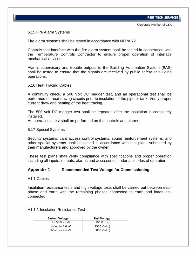
International Operations Business Group
Corporate Member of CSA
REEF TECH SERVICES
5.15 Fire Alarm Systems Fire alarm systems shall be tested in accordance with NFPA 72. Controls that interface with the fire alarm system shall be tested in cooperation with the Temperature Controls Contractor to ensure proper operation of interface mechanical devices. Alarm, supervisory and trouble outputs to the Building Automation System (BAS) shall be tested to ensure that the signals are received by public safety or building operations. 5.16 Heat Tracing Cables A continuity check, a 500 Volt DC megger test, and an operational test shall be performed on heat tracing circuits prior to insulation of the pipe or tank. Verify proper current draw and heating of the heat tracing. The 500 volt DC megger test shall be repeated after the insulation is completely installed. An operational test shall be performed on the controls and alarms. 5.17 Special Systems Security systems, card access control systems, sound reinforcement systems, and other special systems shall be tested in accordance with test plans submitted by their manufacturers and approved by the owner. These test plans shall verify compliance with specifications and proper operation including all inputs, outputs, alarms and accessories under all modes of operation.
Appendix 1 Recommended Test Voltage for Commissioning A1.1 Cables Insulation resistance tests and high voltage tests shall be carried out between each phase and earth with the remaining phases connected to earth and loads dis-connected. A1.1.1 Insulation Resistance Test
System Voltage Test Voltage LV 50 V - 1 kV 500 V (d.c)
HV up to 4.6 kV 2500 V (d.c) HV above 4.6 kV 5000 V (d.c)
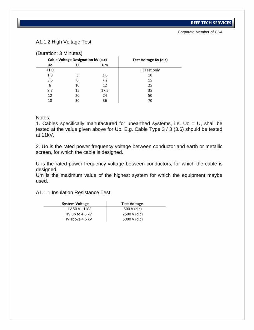
International Operations Business Group
Corporate Member of CSA
REEF TECH SERVICES
A1.1.2 High Voltage Test (Duration: 3 Minutes)
Notes: 1. Cables specifically manufactured for unearthed systems, i.e. Uo = U, shall be tested at the value given above for Uo. E.g. Cable Type 3 / 3 (3.6) should be tested at 11kV. 2. Uo is the rated power frequency voltage between conductor and earth or metallic screen, for which the cable is designed. U is the rated power frequency voltage between conductors, for which the cable is designed. Um is the maximum value of the highest system for which the equipment maybe used. A1.1.1 Insulation Resistance Test
Test Voltage Kv (d.c)Uo U Um
<1.0 IR Test only1.8 3 3.6 103.6 6 7.2 156 10 12 25
8.7 15 17.5 3512 20 24 5018 30 36 70
Cable Voltage Designation kV (a.c)
System Voltage Test Voltage LV 50 V - 1 kV 500 V (d.c)
HV up to 4.6 kV 2500 V (d.c) HV above 4.6 kV 5000 V (d.c)
International Operations Business Group
Corporate Member of CSA
REEF TECH SERVICES
Vibration Test Procedure
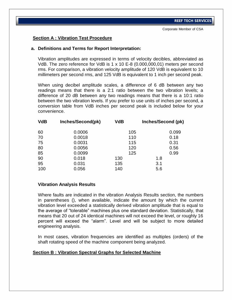
International Operations Business Group
Corporate Member of CSA
REEF TECH SERVICES
Section A : Vibration Test Procedure
a. Definitions and Terms for Report Interpretation: Vibration amplitudes are expressed in terms of velocity decibles, abbreviated as VdB. The zero reference for VdB is 1 x 10 E-8 (0.000,000,01) meters per second rms. For comparison, a vibration velocity amplitude of 120 VdB is equivalent to 10 millimeters per second rms, and 125 VdB is equivalent to 1 inch per second peak. When using decibel amplitude scales, a difference of 6 dB between any two readings means that there is a 2:1 ratio between the two vibration levels; a difference of 20 dB between any two readings means that there is a 10:1 ratio between the two vibration levels. If you prefer to use units of inches per second, a conversion table from VdB inches per second peak is included below for your convenience. VdB Inches/Second(pk) VdB Inches/Second (pk) 60 0.0006 105 0.099 70 0.0018 110 0.18 75 0.0031 115 0.31 80 0.0056 120 0.56 85 0.0099 125 0.99 90 0.018 130 1.8 95 0.031 135 3.1 100 0.056 140 5.6 Vibration Analysis Results Where faults are indicated in the vibration Analysis Results section, the numbers in parentheses (), when available, indicate the amount by which the current vibration level exceeded a statistically derived vibration amplitude that is equal to the average of “tolerable” machines plus one standard deviation. Statistically, that means that 20 out of 24 identical machines will not exceed the level, or roughly 16 percent will exceed the “alarm”. Level and will be subject to more detailed engineering analysis. In most cases, vibration frequencies are identified as multiples (orders) of the shaft rotating speed of the machine component being analyzed.
Section B : Vibration Spectral Graphs for Selected Machine
International Operations Business Group
Corporate Member of CSA
REEF TECH SERVICES
Standard Test Forms
International Operations Business Group
Corporate Member of CSA
REEF TECH SERVICES
Index Form No. Description
Mechanical
A1 Commissioning Activity Schedule – Air System
A2i Air Distribution System Check Sheet
A2ii Fan Mechanical Check Sheets
A2iii Pre Commissioning Sheet - FAHU
A2iv Pre Commissioning Sheet - AHU
A2v Pre Commissioning Sheet - Fan
A2vi Pre Commissioning Sheet - FCU
A3i Performance Sheet - FAHU
A3ii Performance Sheet - AHU
A3iii Performance Sheet Fan
A3iv Performance Sheet - FCU
A4ia Traverse Sheet
A4ib Anemometer Test Sheet
A4ii Air Balance Sheet - Terminal
A4iii Air Balance Sheet - VAV
A4iv Schematic Diagram Sheet
S3 Performance Test Record Noise Level Measurement
S4 Sound and Environmental Sheet
T1 Space Temperatures
T2 Temperature and Humidity Record
W1 Commissioning Activity Schedule – Water System
W2 Pre Commissioning Sheet – Water System
W3 Pump Performance Sheet
W3ia Water Balance Sheet - Main System DRV
W3ib Water Balance Sheet - DRV
W3ii Flow Verification Sheet - Dynamic Balancing Valves
W3iii Flow Verification Sheet - Ultrasonic Measurement
International Operations Business Group
Corporate Member of CSA
REEF TECH SERVICES
W3iv Flow Verification Sheet - Double Regulating Valves (DRV) &
Dynamic Balancing Valves (DBV)
Misc1 Ceiling Closure Check Sheet
Misc2 Mechanical Fire Damper Functionality Test Sheets
Misc3 Condensing Unit Performance Test Sheet
Misc4 Dx Split Performance Test Sheet
Electrical
E1 Electrical System Check List
E2 Pre - Commissioning Check List for Earthing System
E3 Pre - Commissioning Check List for SMDB
E4 Pre - Commissioning Check List for DB
E5 Earth Testing Report
E6 Insulation Resistance and Continuity Test Report for SMDB
E7 Insulation Resistance and Continuity Test Report for DB
(Lighting & small Power Distribution)
E8 Pre - Commissioning Check List for MDB
E9 Insulation Resistance and Continuity Test Report for MDB
E10 Pre - Commissioning Check List for Generator
E11 Commissioning Sheet and Certificate for Generator
E12 Pre - Commissioning Check List for Capacitor Bank
E13 Insulation Resistance and Continuity Test Report for Capacitor
Bank
E14 Continuity and Test Report for Lighting Control
Plumbing and Drainage System
P1 Water Supply and Sanitary Ware Commissioning Checklist