damageability of gas turbine blades evaluation of …the shaft, i.e. th e turbine blade rim. x...
TRANSCRIPT
19
Damageability of Gas Turbine Blades – Evaluation of Exhaust Gas Temperature in Front
of the Turbine Using a Non-Linear Observer
Józef Błachnio and Wojciech Izydor Pawlak Air Force Institute of Technology (Instytut Techniczny Wojsk Lotniczxych-ITWL),
Poland
1. Introduction
A turbine is a fluid-flow machine that converts enthalpy of the working agent, also referred
to as the thermodynamic agent (a stream of exhaust gas, gaseous products of decomposition
reactions or compressed gas) into mechanical work that results in the rotation of the turbine
rotor. This available work, together with the mass flow intensity of the working agent,
define power that can be developed by the turbine and subsequently used to drive various
pieces of equipment (e.g. compressors of turbojet engines). The basic advantages of gas
turbines include: possibility to develop high power at rather compact dimensions and low
bare weight, relatively high efficiency of the energy conversion process, simple design and
high reliability of operation (Błachnio, 2004, 2007; Kroes et al., 1992; Sieniawski, 1995). On
the other hand, the drawbacks are: high operating temperatures of some components,
sophisticated geometrical shapes of the components, e.g. blades and vanes, which makes the
manufacturing process difficult, as well as high working speeds of rotors that impose the
need to apply reduction gears, e.g. when turbine-power receivers show limited rotational
speeds.
Because of the direction of flow of the exhaust gas, turbines are classified as axial-flow and
radial-flow systems. Each turbine is made up of two basic subassemblies that compose the
turbine stage.
A stationary rim with profiled vanes fixed co-axially (axial-flow turbines) or in parallel
(radial-flow turbines), i.e. the so-called turbine nozzle guide vanes, or shortly, the
stator;
A moving rim (one or several ones) with profiled blades fixed circumferentially (axial-
flow turbines) or on the face surface (radial-flow turbines) of a rotating disk seated on
the shaft, i.e. the turbine blade rim.
Depending on the distribution of the inlet energy of exhaust gases among basic
subassemblies, turbines are classified as:
action (impulse) turbines, - the exhaust gases are subject to decompression
exclusively in turbine nozzle guide vanes,
reaction turbines - the exhaust gases are decompressed by both the guide vanes
(stator vanes) and in the turbine rotor.
www.intechopen.com
Advances in Gas Turbine Technology
436
In industrial-type turbines a portion of the produced energy is used to drive a compressor,
whereas the rest of it - to generate power transmitted then to power receivers. In
aeronautical applications, the gas turbine is a structural component of a turbojet, a
turboprop or a helicopter engine. The turbine power affects the engine performance;
improvement in the turbine efficiency results in the engine thrust (power) increase and
reduction in the unit fuel consumption.
Gas turbines, designed for industrial plants, vehicles, off-shore applications, power
engineering systems, and aeronautical applications offer pretty high efficiency of 30 to
45% (Błachnio, 2004; Kroes et al., 19920). That efficiency depends, and to a very high
degree, on temperature of exhaust gases at the turbine inlet. Over the recent years this
temperature has increased by more than 450 K, which has resulted in substantial
improvement in overall efficiency offered by turbines and made it possible to achieve
even higher coefficient of unit power. Particular attention has been paid to increase heat
resistance and high-temperature creep resistance of turbine components, especially of the
1st stage vanes and blades. For that purpose, dedicated systems are applied to cool down
the vanes and blades in order to secure reliable operation of the machine under heavy-
duty thermal and mechanical loads. This, in turn, reduces the working temperature of the
material by as much as 625 K as compared to the exhaust gas temperature. It is much
easier to develop a cooling system when designers deal with large vanes and blades.
Application of similar cooling systems to compact turbines is associated with undesirable
drop in the turbine efficiency. This is why further development of the turbine-blade
production engineering processes, aimed at capabilities to increase temperature upstream
the turbine, has been focused on spreading heat-resistant coatings showing good
resistance to high-temperature corrosion, low thermal conductivity, and high stability of
the material structure. The operating temperature of turbine blades and vanes can be
maintained within the following intervals: (Błachnio, 2007; Kroes et al., 1992; Paton, 1997;
Sieniawski, 1995; Taira and Ohtani, 1986), depending on structural materials used and
cooling intensity:
1100 - 1200 K (when no dedicated cooling system is applied);
1200 - 1300 K (when blade/vane cooling system is applied);
1300 K and above (when an intense-cooling system is applied).
Moreover, vanes and blades are coated with materials that enable increase in blade/vane
operating temperature. However, a highly sophisticated design and manufacture
engineering processes increase the production overheads.
2. Description of failures to gas turbine vanes and blades
The process of gas turbine operation is associated with various failures to structural
components of gas turbines, in particular blades. Condition of the blades is of crucial
importance to reliability and lifetime of the entire turbine, and the ‘parent’ subassembly
where it is installed. This is why the blades are subject to scrupulous checks, both during the
manufacture and at the stage of assembly, when any deviations from the specification are
detected and eliminated. Analysis of the literature and own experience (Błachnio, 2007;
Błachnio & Bogdan, 2008; Hernas, 1999; Nikitin, 1987) show that only a small portion of
damages/failures to turbine vanes and blades are caused by material defects, structural
www.intechopen.com
Damageability of Gas Turbine Blades – Evaluation of Exhaust Gas Temperature in Front of the Turbine Using a Non-Linear Observer
437
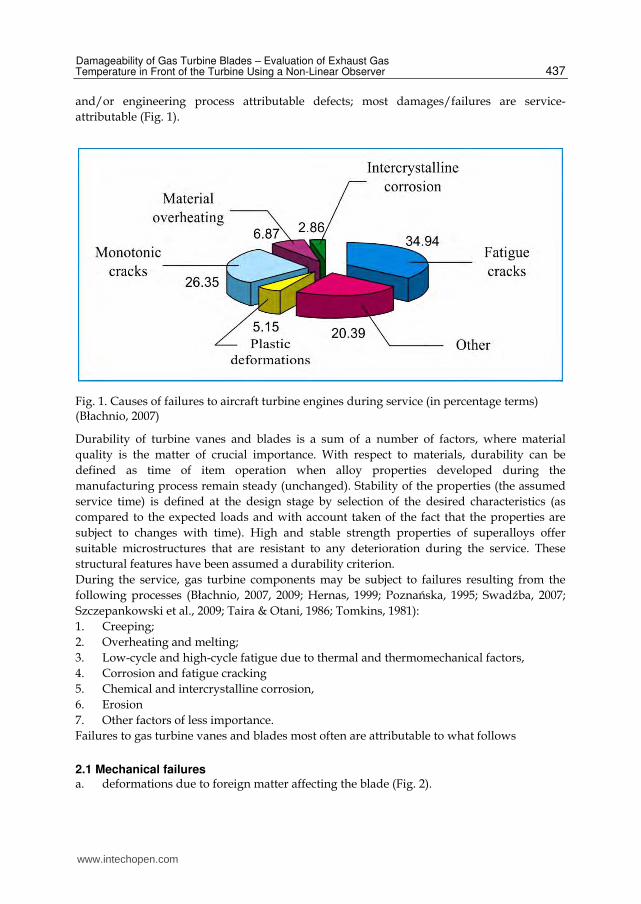
and/or engineering process attributable defects; most damages/failures are service-
attributable (Fig. 1).
Fig. 1. Causes of failures to aircraft turbine engines during service (in percentage terms) (Błachnio, 2007)
Durability of turbine vanes and blades is a sum of a number of factors, where material
quality is the matter of crucial importance. With respect to materials, durability can be
defined as time of item operation when alloy properties developed during the
manufacturing process remain steady (unchanged). Stability of the properties (the assumed
service time) is defined at the design stage by selection of the desired characteristics (as
compared to the expected loads and with account taken of the fact that the properties are
subject to changes with time). High and stable strength properties of superalloys offer
suitable microstructures that are resistant to any deterioration during the service. These
structural features have been assumed a durability criterion.
During the service, gas turbine components may be subject to failures resulting from the
following processes (Błachnio, 2007, 2009; Hernas, 1999; Poznańska, 1995; Swadźba, 2007;
Szczepankowski et al., 2009; Taira & Otani, 1986; Tomkins, 1981):
1. Creeping;
2. Overheating and melting;
3. Low-cycle and high-cycle fatigue due to thermal and thermomechanical factors,
4. Corrosion and fatigue cracking
5. Chemical and intercrystalline corrosion,
6. Erosion
7. Other factors of less importance.
Failures to gas turbine vanes and blades most often are attributable to what follows
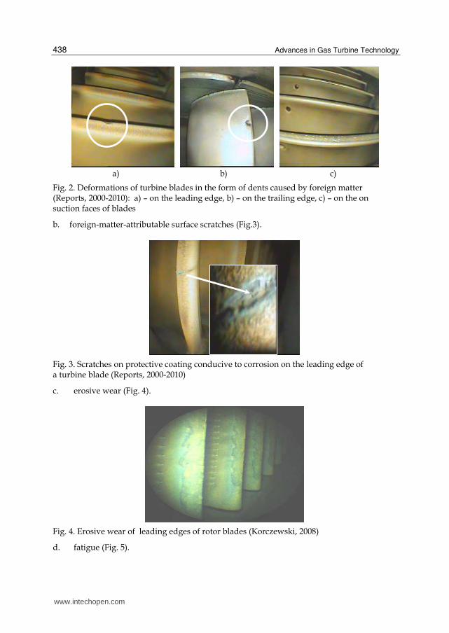
2.1 Mechanical failures a. deformations due to foreign matter affecting the blade (Fig. 2).
www.intechopen.com
Advances in Gas Turbine Technology
438
a) b) c)
Fig. 2. Deformations of turbine blades in the form of dents caused by foreign matter (Reports, 2000-2010): a) – on the leading edge, b) – on the trailing edge, c) – on the on suction faces of blades
b. foreign-matter-attributable surface scratches (Fig.3).
Fig. 3. Scratches on protective coating conducive to corrosion on the leading edge of a turbine blade (Reports, 2000-2010)
c. erosive wear (Fig. 4).
Fig. 4. Erosive wear of leading edges of rotor blades (Korczewski, 2008)
d. fatigue (Fig. 5).
www.intechopen.com

Damageability of Gas Turbine Blades – Evaluation of Exhaust Gas Temperature in Front of the Turbine Using a Non-Linear Observer
439
a) b)
Fig. 5. Failures to gas turbine rotor blades caused by (Reports, 2000-2010): a) – fatigue cracking of leading edge, b) – fatigue fracture located at the blade’s locking piece
2.2 Thermal failures a. creeping (Fig.6).
Fig. 6. Plastic deformation of the blade (Bogdan, 2009).
b. overheating of blade material (Fig. 7)
a) b) c)
Fig. 7. Characteristic forms of failures caused by overheating of blade material (Reports, 2000-2010): a– partial melting of blade’s trailing edge, b) – cracks on blade’s leading edge, c) – breakaway of the blade (Błachnio, 2010)
c. melting of the vane material (Fig. 8)
Neck-down
www.intechopen.com

Advances in Gas Turbine Technology
440
a) b)
Fig. 8. Characteristic forms of failures to gas turbine caused by long-lasting excessive temperature of exhaust gases (Reports, 2000-2010) : a) – burn-through of turbine rotor blades, b) – melting of a nozzle vane
2.3 Chemical failures a. high-temperature corrosion (Fig. 9)
a) b)
Fig. 9. Failures to turbine blades operated in the seashore environment, caused by chemical impact of exhaust gases (Reports, 2000-2010): a) – on blade surface, b) – on blade leading edge
b. intercrystalline corrosion (Fig. 10). Blade deformations in the form of dents (Fig. 2) are caused by a foreign matter ingested by the turbojet engine compressor and by particles of metal and hard carbon deposits from the combustion chamber. Such dents result in stress concentrations in blade material and prove conducive to the initiation of fatigue processes. Scratches on blade surfaces (Fig. 3) due to the foreign matter impact are also reasons for local stress concentrations and, consequently, potential corrosion centers. What results is, again, material fatigue which, together with possible corrosion, prove conducive to fatigue fracture.
www.intechopen.com
Damageability of Gas Turbine Blades – Evaluation of Exhaust Gas Temperature in Front of the Turbine Using a Non-Linear Observer
441
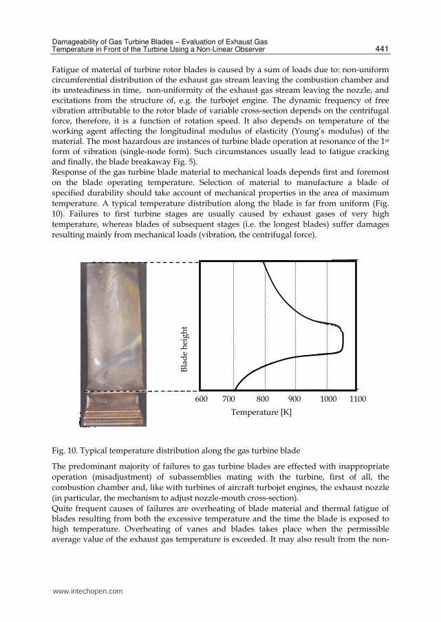
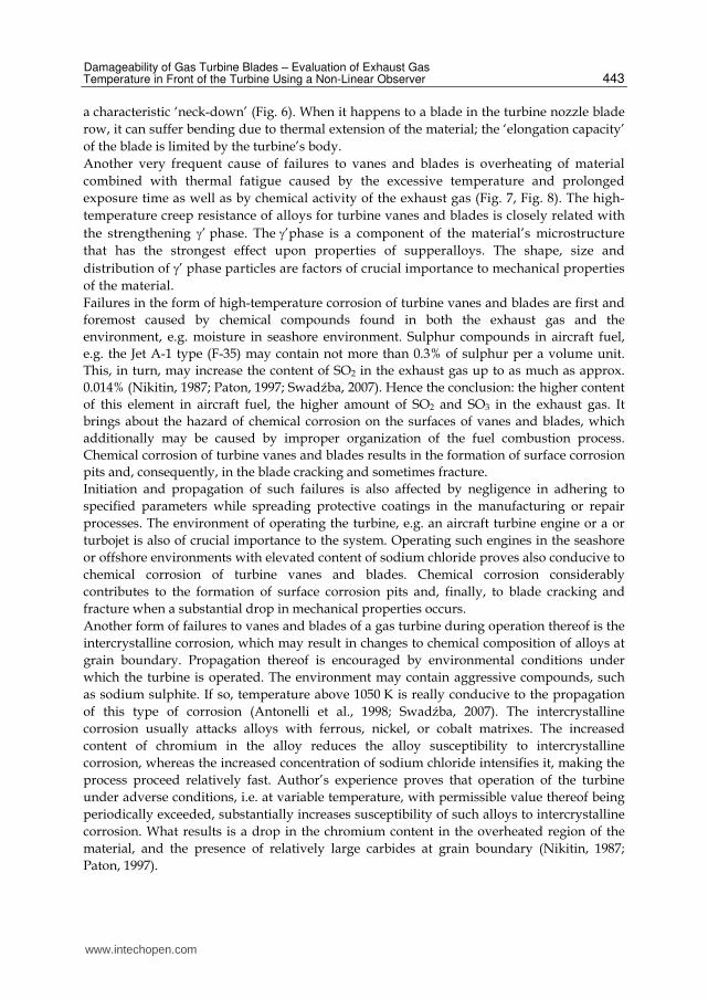
Fatigue of material of turbine rotor blades is caused by a sum of loads due to: non-uniform circumferential distribution of the exhaust gas stream leaving the combustion chamber and its unsteadiness in time, non-uniformity of the exhaust gas stream leaving the nozzle, and excitations from the structure of, e.g. the turbojet engine. The dynamic frequency of free vibration attributable to the rotor blade of variable cross-section depends on the centrifugal force, therefore, it is a function of rotation speed. It also depends on temperature of the working agent affecting the longitudinal modulus of elasticity (Young’s modulus) of the material. The most hazardous are instances of turbine blade operation at resonance of the 1st form of vibration (single-node form). Such circumstances usually lead to fatigue cracking and finally, the blade breakaway Fig. 5). Response of the gas turbine blade material to mechanical loads depends first and foremost
on the blade operating temperature. Selection of material to manufacture a blade of
specified durability should take account of mechanical properties in the area of maximum
temperature. A typical temperature distribution along the blade is far from uniform (Fig.
10). Failures to first turbine stages are usually caused by exhaust gases of very high
temperature, whereas blades of subsequent stages (i.e. the longest blades) suffer damages
resulting mainly from mechanical loads (vibration, the centrifugal force).
Fig. 10. Typical temperature distribution along the gas turbine blade
The predominant majority of failures to gas turbine blades are effected with inappropriate
operation (misadjustment) of subassemblies mating with the turbine, first of all, the
combustion chamber and, like with turbines of aircraft turbojet engines, the exhaust nozzle
(in particular, the mechanism to adjust nozzle-mouth cross-section).
Quite frequent causes of failures are overheating of blade material and thermal fatigue of blades resulting from both the excessive temperature and the time the blade is exposed to high temperature. Overheating of vanes and blades takes place when the permissible average value of the exhaust gas temperature is exceeded. It may also result from the non-
600 700 800 900 1000 1100
Temperature [K]
Bla
de
hei
gh
t
www.intechopen.com

Advances in Gas Turbine Technology
442
uniform circumferential temperature distribution (Fig. 11). One of possible causes of non-uniform temperature distribution downstream the turbine lies in the improper fuel atomization due to excessive carbon deposit on fuel injectors (Fig. 12).
Fig. 11. Instantaneous circumferential non-uniform temperature T4 distribution measured with 8 thermoelements (T4t1 –T4t8) located behind the turbine; measurements taken at increasing/decreasing rotational speeds
a) b)
Fig. 12. Condition of combustion-chamber injectors: a) – clean, b) – polluted with carbon deposits from fuel
Elongation of the plasticized material of a rotor blade results from the blade being affected
with overcritical temperature and centrifugal force. In such cases the rotor blade shows
973 873 773 673 573
800 900 1000 1100 1200
T4t ÷T4t
Time [s]
Tem
per
atu
re [
K]
www.intechopen.com
Damageability of Gas Turbine Blades – Evaluation of Exhaust Gas Temperature in Front of the Turbine Using a Non-Linear Observer
443
a characteristic ‘neck-down’ (Fig. 6). When it happens to a blade in the turbine nozzle blade
row, it can suffer bending due to thermal extension of the material; the ‘elongation capacity’
of the blade is limited by the turbine’s body.
Another very frequent cause of failures to vanes and blades is overheating of material
combined with thermal fatigue caused by the excessive temperature and prolonged
exposure time as well as by chemical activity of the exhaust gas (Fig. 7, Fig. 8). The high-
temperature creep resistance of alloys for turbine vanes and blades is closely related with
the strengthening ’ phase. The ’phase is a component of the material’s microstructure
that has the strongest effect upon properties of supperalloys. The shape, size and
distribution of ’ phase particles are factors of crucial importance to mechanical properties
of the material.
Failures in the form of high-temperature corrosion of turbine vanes and blades are first and
foremost caused by chemical compounds found in both the exhaust gas and the
environment, e.g. moisture in seashore environment. Sulphur compounds in aircraft fuel,
e.g. the Jet A-1 type (F-35) may contain not more than 0.3% of sulphur per a volume unit.
This, in turn, may increase the content of SO2 in the exhaust gas up to as much as approx.
0.014% (Nikitin, 1987; Paton, 1997; Swadźba, 2007). Hence the conclusion: the higher content
of this element in aircraft fuel, the higher amount of SO2 and SO3 in the exhaust gas. It
brings about the hazard of chemical corrosion on the surfaces of vanes and blades, which
additionally may be caused by improper organization of the fuel combustion process.
Chemical corrosion of turbine vanes and blades results in the formation of surface corrosion
pits and, consequently, in the blade cracking and sometimes fracture.
Initiation and propagation of such failures is also affected by negligence in adhering to
specified parameters while spreading protective coatings in the manufacturing or repair
processes. The environment of operating the turbine, e.g. an aircraft turbine engine or a or
turbojet is also of crucial importance to the system. Operating such engines in the seashore
or offshore environments with elevated content of sodium chloride proves also conducive to
chemical corrosion of turbine vanes and blades. Chemical corrosion considerably
contributes to the formation of surface corrosion pits and, finally, to blade cracking and
fracture when a substantial drop in mechanical properties occurs.
Another form of failures to vanes and blades of a gas turbine during operation thereof is the
intercrystalline corrosion, which may result in changes to chemical composition of alloys at
grain boundary. Propagation thereof is encouraged by environmental conditions under
which the turbine is operated. The environment may contain aggressive compounds, such
as sodium sulphite. If so, temperature above 1050 K is really conducive to the propagation
of this type of corrosion (Antonelli et al., 1998; Swadźba, 2007). The intercrystalline
corrosion usually attacks alloys with ferrous, nickel, or cobalt matrixes. The increased
content of chromium in the alloy reduces the alloy susceptibility to intercrystalline
corrosion, whereas the increased concentration of sodium chloride intensifies it, making the
process proceed relatively fast. Author’s experience proves that operation of the turbine
under adverse conditions, i.e. at variable temperature, with permissible value thereof being
periodically exceeded, substantially increases susceptibility of such alloys to intercrystalline
corrosion. What results is a drop in the chromium content in the overheated region of the
material, and the presence of relatively large carbides at grain boundary (Nikitin, 1987;
Paton, 1997).
www.intechopen.com

Advances in Gas Turbine Technology
444
3. The assessment of condition of gas turbine vanes/blades throughout the operational phase
Throughout the operational phase of any gas turbine various forms of failures to turbine components may occur. These failures, different in intensity, may result in the malfunction of the turbine, and sometimes even in a notifiable accident, as e.g. in aviation. Failures/damages are always remedied by a major repair or overhaul of the turbine, both of which generate huge costs. The cost of engine major repair, not to mention an overhaul, are several thousand as high as unit price of a single vane or blade. Any decision on whether the engine needs repair is taken by a diagnostic engineer who performs visual inspection with, e.g. a videoscope (Fig. 13) and is able to inspect and diagnose condition of difficult of access turbine components. The condition assessment is performed using a recorded image of the inspected component’s surface and comparing it with pattern images of surfaces of serviceable and unserviceable (fit/unfit for use) components, e.g. analogous vanes and blades of the turbine. An experienced diagnostic engineer is capable of assessing the risk that failures such as dents, melting of materials, fatigue cracks or corrosion may pose. However, the assessment of, e.g. overheated material is much more difficult as it has to be based on the colour of the blade surface (Fig. 14).
Fig. 13. An industrial videoscope and an image of gas turbine blades condition (Reports, 2000-2010)
Fig. 14. A gas turbine with visible changes in colour on surfaces of vanes – the evidence of different degrees of vane overheating (Reports, 2000-2010)
www.intechopen.com

Damageability of Gas Turbine Blades – Evaluation of Exhaust Gas Temperature in Front of the Turbine Using a Non-Linear Observer
445
Such an assessment can be carried out using, e.g. a table of colours typical of the layer of oxides and corresponding temperatures upon a vane/blade fracture if the vane/blade is air-cooled (Table 1).
Temperature [K] Colour of a layer of oxides upon vane fracture
~ 670 light gray
~ 770 light gray with a pale yellow shadow
~ 870 bright yellow
~ 920 yellow, dark yellow
~ 970 yellowish brown
~ 1020 yellowish brown with violet shadow
~ 1070 dark violet
~ 1120 blue, navy blue
Table 1. Colour of layer of oxides and corresponding temperatures upon vane/blade fracture if the vane/blade is air-cooled (Bogdan, 2009)
The trustworthiness of the condition assessment depends on a number of factors, i.e. skills
and experience of the diagnostic engineer, the diagnostic method applied, condition of
diagnostic instruments, external circumstances of the experiment, etc. To a large extent it is
a subjective assessment by the diagnostic engineer, which always poses some risk R of the
decision taken; the risk is expressed by the following formula (Błachnio & Bogdan, 2008).
.
0
1 1 1 0
11 21
0
0
0 1 0 0
12 22
0
( ) ( / ) ( ) ( / )
( ) ( / ) ( ) ( / )
y
n n
y
y
n n
y
R c p w f y w dy c p w f y w dy
c p w f y w dy c p w f y w dy
. (1)
where:
0
1 0( ) ( / )ny
p w f y w dy
probability of the 1st class error (a serviceable/fit-for-use object is assessed as an unserviceable/unfit-for-use one, probability of a false alarm, risk of placing an order),
00 1( ) ( / )
y
np w f y w dy
probability of the 2nd class error (an unserviceable/ unfit-for-use object is assessed as a serviceable/fit-for-use one, contractor’s risk),
c21 = w21 – cost (loss) in case of the 1st class error
cl2 = wl2 – cost (loss) in case of the 2nd class error
c11 = w11, c22 = w22 – right decision related cost (loss)
w0 – status of serviceability, w1 – status of unserviceability, y0 – initial value of the status parameter, yn – final value of the status parameter.
www.intechopen.com
Advances in Gas Turbine Technology
446
Mistakes resulting from the subjective assessment carried out by the diagnostic engineer may lead to that the overheated vane is taken for a good one, and vice versa, the good one for an overheated one. In the first case, after a pretty short time of engine operation an air accident occurs, whereas the second-type mistake entails enormous cost of a major repair/overhaul of the engine. The assessment provided by the diagnosing engineer is verified with a destructive method, i.e. the microsection of the vane/blade in question is carefully analysed. As already mentioned, the most difficult for type identification and for classification of vane/blade condition are failures in the form of material overheating, in particular of uncooled items. sometimes Apart from the strict bipolar classification ‘serviceable/fit-for-use – unserviceable/unfit-for-use’, in some instances of diagnosing vane/blade condition, the third, intermediate level of the component-condition assessment is used, namely the ‘partly serviceable/fit-for-use’. This classification is applicable to, among other things, gas turbines installed, e.g. in aircraft turbojet engines, i.e. to very expensive systems expected (and required) to show the possibly maximum cost effectiveness (the ‘durability to cost-of-operation’ ratio). Therefore, if the diagnostic engineer delivers his subjective assessment with regard to the degree of overheating understood as a change in colour intensity, and to the size and location of the overheated area on the vane/blade, the three-grade assessment scale is applicable. If it is recognised that the degree of overheating suggests the vane/blade is classified to the ‘partly serviceable/fit-for-use’ category, the current assessment of the vane/blade condition is periodically carried out until the item reaches the ‘unserviceable/ unfit-for-use’ condition. Consequently, the turbine’s life, i.e. its time of operation after a failure had occurred to a vane/blade (of an expensive aircraft engine) can be extended; the cost of engine operation is also reduced. Obviously, the flight-safety level of an aircraft with an engine furnished with a periodically diagnosed turbine cannot be compromised. Currently, there are no unbiased criteria that enable unambiguous in-service assessment of the degree of overheating of vane/blade material with non-destructive methods. The case illustrated in Fig. 14 – there is no chance to unambiguously assess whether the surface of at least one vane exhibits symptoms of the material overheating, needless to say that nothing can be concluded about the degree of overheating if only the already existing criteria can be applied.
4. Examination of microstructures of damaged gas turbine blades
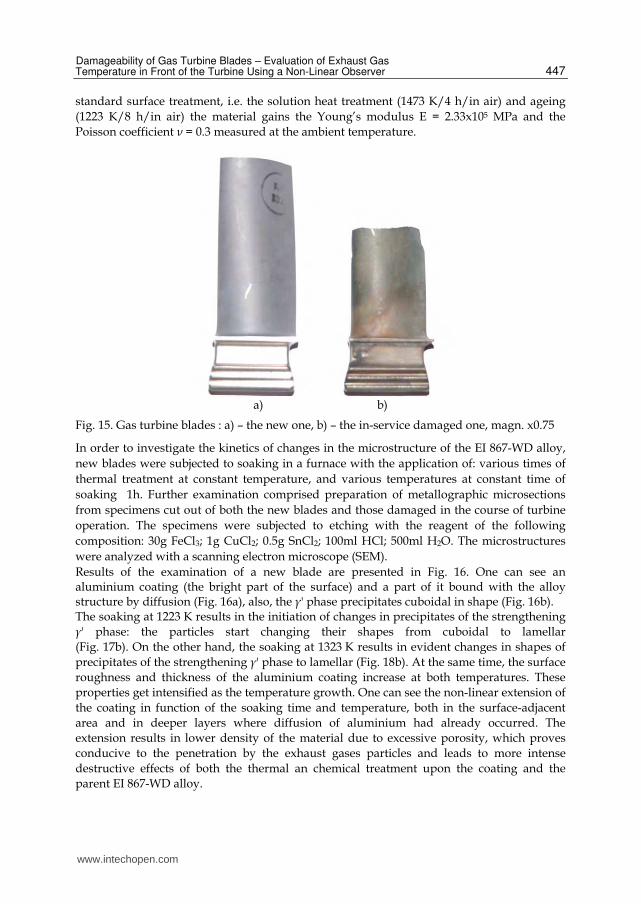
4.1 Object and methodology of the examination Subject to examination were gas turbine blades with in-service damages (Fig. 15). Changes in the microstructure of a blade that has already been operated can be assessed on the basis of changes demonstrated by a new blade subjected to temperature within a specified range, and exposed to this temperature for sufficiently long time. The examined blades were manufactured of the nickel-based superalloy EI 867-WD
(HN62MWKJu-WD – to TC-14-1-223-72) intended for thermal-mechanical treatment, of he
following chemical composition (% by weight): C = 0.03; Si = 0.14; Mn = 0.06; S = 0.005; P =
0.005; Cr = 9.69; Al = 4.65; W = 4.69; Mo = 9.29; Co = 4.84; Fe = 0.39; Ni = the rest. The
manufacturing process comprises such processes as hot forging, surface machining by
grinding, milling and polishing (Błachnio, 2009). The next step is thermal and chemical
treatment of blades that consists in the introduction of aluminium to their surface layer in
order to increase their resistance to thermal and chemical effect of exhaust gases. After the
www.intechopen.com
Damageability of Gas Turbine Blades – Evaluation of Exhaust Gas Temperature in Front of the Turbine Using a Non-Linear Observer
447
standard surface treatment, i.e. the solution heat treatment (1473 K/4 h/in air) and ageing
(1223 K/8 h/in air) the material gains the Young’s modulus E = 2.33x10⁵ MPa and the
Poisson coefficient ν = 0.3 measured at the ambient temperature.
a) b)
Fig. 15. Gas turbine blades : a) – the new one, b) – the in-service damaged one, magn. x0.75
In order to investigate the kinetics of changes in the microstructure of the EI 867-WD alloy,
new blades were subjected to soaking in a furnace with the application of: various times of
thermal treatment at constant temperature, and various temperatures at constant time of
soaking 1h. Further examination comprised preparation of metallographic microsections
from specimens cut out of both the new blades and those damaged in the course of turbine
operation. The specimens were subjected to etching with the reagent of the following
composition: 30g FeCl3; 1g CuCl2; 0.5g SnCl2; 100ml HCl; 500ml H2O. The microstructures
were analyzed with a scanning electron microscope (SEM).
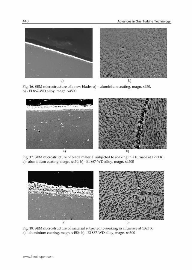
Results of the examination of a new blade are presented in Fig. 16. One can see an aluminium coating (the bright part of the surface) and a part of it bound with the alloy structure by diffusion (Fig. 16a), also, the γ' phase precipitates cuboidal in shape (Fig. 16b). The soaking at 1223 K results in the initiation of changes in precipitates of the strengthening
γ' phase: the particles start changing their shapes from cuboidal to lamellar
(Fig. 17b). On the other hand, the soaking at 1323 K results in evident changes in shapes of
precipitates of the strengthening γ' phase to lamellar (Fig. 18b). At the same time, the surface
roughness and thickness of the aluminium coating increase at both temperatures. These
properties get intensified as the temperature growth. One can see the non-linear extension of
the coating in function of the soaking time and temperature, both in the surface-adjacent
area and in deeper layers where diffusion of aluminium had already occurred. The
extension results in lower density of the material due to excessive porosity, which proves
conducive to the penetration by the exhaust gases particles and leads to more intense
destructive effects of both the thermal an chemical treatment upon the coating and the
parent EI 867-WD alloy.
www.intechopen.com
Advances in Gas Turbine Technology
448
a) b)
Fig. 16. SEM microstructure of a new blade: a) – aluminium coating, magn. x450, b) - EI 867-WD alloy, magn. x4500
a) b)
Fig. 17. SEM microstructure of blade material subjected to soaking in a furnace at 1223 K: a)– aluminium coating, magn. x450, b) - EI 867-WD alloy, magn. x4500
a) b)
Fig. 18. SEM microstructure of material subjected to soaking in a furnace at 1323 K: a) - aluminium coating, magn. x450; b) - EI 867-WD alloy, magn. x4500
www.intechopen.com
Damageability of Gas Turbine Blades – Evaluation of Exhaust Gas Temperature in Front of the Turbine Using a Non-Linear Observer
449
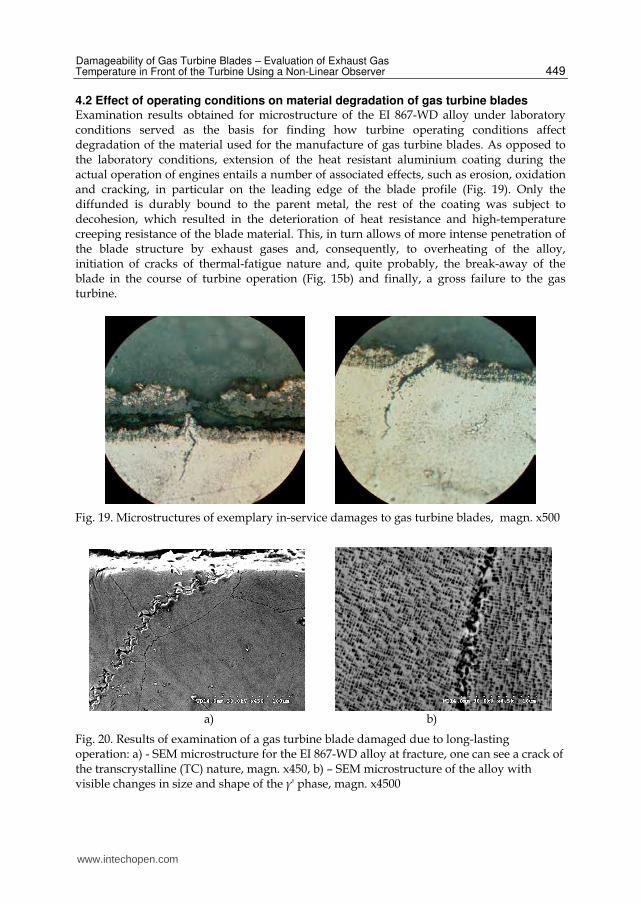
4.2 Effect of operating conditions on material degradation of gas turbine blades Examination results obtained for microstructure of the EI 867-WD alloy under laboratory conditions served as the basis for finding how turbine operating conditions affect degradation of the material used for the manufacture of gas turbine blades. As opposed to the laboratory conditions, extension of the heat resistant aluminium coating during the actual operation of engines entails a number of associated effects, such as erosion, oxidation and cracking, in particular on the leading edge of the blade profile (Fig. 19). Only the diffunded is durably bound to the parent metal, the rest of the coating was subject to decohesion, which resulted in the deterioration of heat resistance and high-temperature creeping resistance of the blade material. This, in turn allows of more intense penetration of the blade structure by exhaust gases and, consequently, to overheating of the alloy, initiation of cracks of thermal-fatigue nature and, quite probably, the break-away of the blade in the course of turbine operation (Fig. 15b) and finally, a gross failure to the gas turbine.
Fig. 19. Microstructures of exemplary in-service damages to gas turbine blades, magn. x500
a) b)
Fig. 20. Results of examination of a gas turbine blade damaged due to long-lasting operation: a) - SEM microstructure for the EI 867-WD alloy at fracture, one can see a crack of the transcrystalline (TC) nature, magn. x450, b) – SEM microstructure of the alloy with visible changes in size and shape of the γ' phase, magn. x4500
www.intechopen.com
Advances in Gas Turbine Technology
450
Metallographic examination of specimens taken from an overheated blade (Fig. 15b) made it possible to find out degradation of the blade microstructure. Numerous microcracks along grain borundaries and transcrystalline ones were detected nearby the blade fracture (Fig. 20a). According to the studies (Okrajni & Plaza, 1995; Sieniawski, 1995; Tomkins, 1981), such decohesion results from the creeping and fatigue processes. The metallographic microsection enabled detection of the γ' phase coagulation. The coagulation and the precipitates dissolving effects intensify nearby the blade surface. In addition, fine-dispersion secondary precipitates are observed; the presence thereof increases susceptibility of the alloy to brittle cracking (Fig. 20a). Extension of the γ' phase in the alloy results in the change of phase shapes from cuboidal (Fig. 16b) to lamellar ones (Fig. 20b) as well as substantial extension of the size of this phase as compared to a new blade. The morphology of particles within the γ' phase depends on the sign (direction) of the mechanical stress existing inside the blade. The tensile stress that acts along the blade axis in the course of turbine rotor’s rotation is conducive to extension of the γ' phase within the plane that is perpendicular to the direction of stress. Consequently, the initially cuboidally-shaped particles (Fig. 16b) are converted into plates (Fig. 20b), with wider walls disposed perpendicularly to the stress direction whereas narrow walls are perpendicular to the remaining directions of the cube (Majka & Sieniawski, 1998; Paton, 1997). Extension of particles within the γ' phase leads to loss of their stability, which leads to coagulation of some particles and dissolving of other ones (Majka & Sieniawski, 1998). That process takes place above some specific temperature typical of a given phase, and over the time of soaking. According to the results gained, when temperature of 1223 K is exceeded even for a very short time, a very intense extension of the γ'-phase precipitates takes place. This leads to the loss of shape stability and the formation of plates (Fig. 18b and Fig. 20b). This conclusion is also confirmed by results reported in (Majka & Sieniawski, 1998; Paton, 1997). Similar conclusion is outlined by authors of the studies (Poznańska, 1995; Taira & Otani, 1986). With the Udimet 700 alloy as an example one can find that at temperatures above 1093 K precipitates in the form of plates substantially deteriorate the yield strength. This effect one can see in Fig. 21 that presents changes in mechanical properties demonstrated by the EI-867 alloy as a function of temperature. Kinetic characteristics of the γ' phase precipitates depend on the degree of saturation of the alloy matrix, i.e. the γ phase, with the admixture elements of the alloy. Shapes of precipitates depend on the degree of misfit between the lattice of alloy elements and the lattice of the basic material. The authors of (Nikitin, 1987; Paton, 1997) found out that for the misfit factor a = 0.2% the γ' phase is precipitated in the form of spheroid particles, for a = 0.5 – 1 % the
particles of the γ' phase are of cuboidal shape whereas for a = 1.2 % the particles take lamellar shape. The theory of precipitate-based strengthening claims that crucial factors decisive to the degree of strengthening include diameters of the γ' phase particles and distances between them. These parameters depend on the extension rate (that is controlled by the volumetric diffusion) and coagulation of these particles. Chemical composition of the γ' phase substantially affects the value of the lattice parameter aγ' and the associated degree of misfit a to the matrix lattice aγ, where a = (aγ aγ') / aγ. It influences morphology of the γ' and the range of its durability. It turns out that the degree of misfit between parameters of the phase lattices is the function of temperature. According to (Paton, 1997) the highest high-temperature creeping resistance is demonstrated by alloys, where the degree of misfit between the phase lattices is positive (>0) (Fig. 22). The chemical composition, morphology and distribution of the γ' phase
www.intechopen.com

Damageability of Gas Turbine Blades – Evaluation of Exhaust Gas Temperature in Front of the Turbine Using a Non-Linear Observer
451
precipitates within the microstructure are crucial factors that decide mechanical properties of the alloy.
Fig. 21. Alterations in mechanical properties demonstrated by the EI-867 alloy vs. temperature (Poznańska, 1995)
a) b)
Fig. 22. Effect of misfit between parameters of the crystallographic lattice for γ and γ' phases of a nickel alloy onto (Paton, 1997): a) strength limit (at 293 K) and durability limit (at
1373 K and = 80 MPa), b) – strength of a two-phase system
5. The method of assessment of temperature variations measured for exhaust gases upstream the gas turbine using a turbine state non-linear observer
The distinguishing peculiarity of low-cycle loads affecting the so called hot structural
components of aircraft turbine reactive engines is superposition of adverse effects due to
joint and simultaneous impact of both mechanical and thermal loads with high amplitudes.
273 473 673 873 1073 Temperature [K]
Ten
sile
str
eng
th R
m [
MP
a]
Pro
of
stre
ss R
0,2
[MP
a]
1400 1200 1000 800 600
400
200
R
R0 2
A
100 80 60 40
Elo
ng
atio
n A
5 %
www.intechopen.com

Advances in Gas Turbine Technology
452
The detrimental effect is particularly intensified when the engine is operated on a combat or
a combined training and combat aircraft. It happens due to frequent and rapid operation of
the engine control lever by a pilot when the aircraft is forced to make sophisticated
manoeuvres. There are documented examples of substantial differences between low-cycle
loads to engines installed on different aircrafts, for instance the ones that are used for group
aerial stunts in a close line-up. It usually happens that the pilot of the guided aircraft,
located at the line-up side changes the rpm range of the motor much more frequently, up to
several dozens times during a single mission, as compared to the pilot of the guiding aircraft
(Cooper & Carter, 1985). Consequently, the exact spectral measurements for low-cycle loads
of a jet engine during its operation are the matters of crucial importance for unbiased
assessment of its condition as a result of natural wear. To perform that task the researcher
must be in possession of synchronous records for timings of momentary values for rotation
speed of the turbine as well as for the average gas temperature at the outlet of the
combustion chamber and downstream the turbine. In this study, the monitoring is focused
on phenomena attributable to a turbojet engine with the longitudinal cross-section shown in
Fig. 23.
Fig. 23. The design configuration of the turbojet engine under tests with indication of calculation cross-sections of the flow path for the working medium
For the considered engine, temperature measurements for exhaust gases are carried out
with use of a set made up of 8 thermoelements deployed in the channel downstream the
turbine within the plane perpendicular to the flow velocity direction. Measurement results
for the rotor rpm and the gas temperature are stored in the memory of the on-board digital
recorder, along with a set of other parameters that are indispensable for further analyses, in
particular flight parameters of the aircraft and ambient conditions.
List of symbols: Cj – specific fuel consumption Cp23 - average specific heat of the working medium inside the combustion chamber D – convergent jet G2 – mass flow intensity of the working medium at the compressor outlet
www.intechopen.com
Damageability of Gas Turbine Blades – Evaluation of Exhaust Gas Temperature in Front of the Turbine Using a Non-Linear Observer
453
G2r – normalized mass flow intensity of the working medium at the compressor outlet G3 – mass flow intensity of the working medium at the combustion chamber outlet
G3r – normalized mass flow intensity of the working medium at the combustion chamber
outlet
h – increment for numerical integration
k34 – isentropic exponent average value for working medium in turbine
k45 – isentropic exponent average value for working medium in nozzle
KS – combustion chamber
n – rotational speed of the rotor (rpm)
nsr – reduced rotational speed of the compressor
ntr – reduced rotational speed of the turbin
P0 – total pressure of the working medium in the engine inlet
P1- total pressure of the working medium in front of the compressor
P2start – initial total pressure of the working medium downstream the compressor
P4 - total pressure of the working medium inside the convergent jet
P4start – initial total pressure of the working medium inside the convergent jet
PH – ambient pressure
Q – rate of fuel flow
Rg – gas constant
S - compressor T – turbine T1 – total temperature of the working medium upstream the compressor T2 – total temperature of the working medium downstream the compressor T3 – total temperature of the working medium upstream the turbine T4 – total temperature of the working medium downstream the turbine T4t – average temperature of exhaust gases measured with use of a thermoelements set T4tstart – initial average temperature of exhaust gases measured with use of athermoelements set TH – ambient temperature th – past service live in hours
u1,u2 – deviations of iterations
V5 – velocity of gas discharged from the convergent jet
w1,w2 – gain coefficients for iteration loops
Wo – calorific value of fuel
Wu - coefficient of air bleeding from the compressor for the needs of the airplane
ZUP – the system of valves for air bleeding from the compressor to prevent from the
compressor stall
- pressure ratio of the working medium while flowing through the compressor
- pressure ratio of the working medium while flowing through the turbine
- flow rate coefficient for the convergent nozzle
- total pressure preservation coefficient for the convergent nozzle
ks- efficiency of the combustion chamber
s – isentropic efficiency of the compressor
t - isentropic efficiency of the turbine
www.intechopen.com
Advances in Gas Turbine Technology
454
23- the total-pressure preservation coefficient for the combustions chamber flow
- the total-pressure preservation coefficient for the compressor flow.
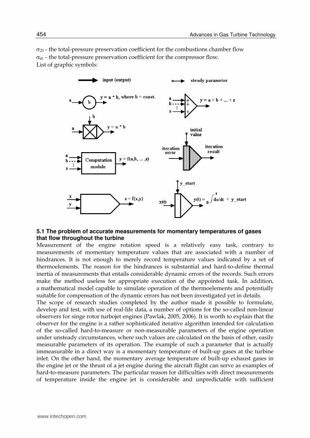
List of graphic symbols:
5.1 The problem of accurate measurements for momentary temperatures of gases that flow throughout the turbine Measurement of the engine rotation speed is a relatively easy task, contrary to measurements of momentary temperature values that are associated with a number of hindrances. It is not enough to merely record temperature values indicated by a set of thermoelements. The reason for the hindrances is substantial and hard-to-define thermal inertia of measurements that entails considerable dynamic errors of the records. Such errors make the method useless for appropriate execution of the appointed task. In addition, a mathematical model capable to simulate operation of the thermoelements and potentially suitable for compensation of the dynamic errors has not been investigated yet in details. The scope of research studies completed by the author made it possible to formulate, develop and test, with use of real-life data, a number of options for the so-called non-linear observers for singe rotor turbojet engines (Pawlak, 2005, 2006). It is worth to explain that the observer for the engine is a rather sophisticated iterative algorithm intended for calculation of the so-called hard-to-measure or non-measurable parameters of the engine operation under unsteady circumstances, where such values are calculated on the basis of other, easily measurable parameters of its operation. The example of such a parameter that is actually immeasurable in a direct way is a momentary temperature of built-up gases at the turbine inlet. On the other hand, the momentary average temperature of built-up exhaust gases in the engine jet or the thrust of a jet engine during the aircraft flight can serve as examples of hard-to-measure parameters. The particular reason for difficulties with direct measurements of temperature inside the engine jet is considerable and unpredictable with sufficient
www.intechopen.com

Damageability of Gas Turbine Blades – Evaluation of Exhaust Gas Temperature in Front of the Turbine Using a Non-Linear Observer
455
accuracy thermal inertia of measuring thermoelement. The inertia results from sizeable dimensions of the thermoelement joint and very broad variation range of both the measured temperature and flow velocity of the exhaust gas stream. The thermoelements installed inside the jet of the engine under tests are made of wires with their diameters of 1.25mm. Such a large diameter of wires is a must due to the required durability of thermoelements that must be placed in the exhaust gas stream with variable flow velocity ranging up to several hundred meters per second and fast-changing temperature from 300 to 1100K. All in all, very high and hard to define with satisfying accuracy thermal inertia of thermoelements is the core reason for troubles with compensation of dynamic errors associated with temperature measurements when the engine operates in an unstationary mode, under various conditions in terms of the flight altitude and speed of the aircraft. On the other hand, exact compensation of measurement deviations for the specific temperature gauge needs perfect familiarity with the mathematical model of the latter. Initial investigations of dynamic deviations for measurements of gas temperature inside the
engine jet with use of thermoelements (Fig. 25) made it possible to find out that
mathematical models in the form of an ordinary non-linear differential equation of 1st range
that have already been used in referenced literature for thermoelements are inadequate
(Michalski & Eckersdorf, 1986; Wiśniewski, 1983). The non-linear observers described in
(Pawlak, 2005, 2006) and intended for scrutinizing operational parameters of turbojet
engines make it possible to find out true characteristic curves for average temperatures of
the built-up gas inside the engine jet (T4) (as well as the mass flow intensity under unsteady
circumstances (G4)) with no need to measure the temperature in a direct way. When
synchronous timings for the actual temperature (T4) determined with use of the observer
and for the temperatures indicate by thermoelements (T4t) are available, one can verify
whether the equality condition for the both temperatures is fulfilled, i.e. T4t = T4 at the
moment when the value of the differential d(T4t)/dt equals zero (although the condition is
obvious for the differential equation of 1st range). Meeting that obvious condition would
serve as the proof for the mathematical model of a thermoelement that is shown in Fig. 24.
in the form of an analog diagram.
Fig. 24. The conventional mathematical model for arrangement of thermal components, reflecting the form of an ordinary non-linear differential equation of 1st range, here called in question
www.intechopen.com

Advances in Gas Turbine Technology
456
5.2 Applicability test for the existing model Fig. 25 shows phase diagrams for the actual temperature (T4), measured indirectly with use of the observer and the temperature (T4t) measured directly with use of the set composed of 8 thermoelements installed inside the jet. The diagrams are plotted as functions of the rotation speed (n) of rotor of the unit made up of the turbine and the compressor. The diagram T4t = f(n) comprises points a, b, c and d, for which dT4t/dt = 0. Dark areas on the graph represent the dynamic error for temperature measurements with use of thermoelements. The analysis of cycles plotted in Fig. 25 serves as the proof that the method that has already been used for mathematical modeling of dynamic properties attributable to thermoelements (Michalski & Eckersdorf, 1986; Wiśniewski, 1983) is inadequate. The diagrams for T4t and T4 temperatures intersect one another only for the phase of full acceleration, i.e. at the ‘a’ and ‘b’ points, whereas a slight discrepancy is observed for the ‘c’ point. Even still insufficient (for the current phase of developments) accuracy of the employed observer cannot serve as explanation for such a large quality divergence between diagrams for the T4t and T4 temperatures during the engine deceleration and for the fact that the diagrams do not intersect at the ‘d’ point. Additionally, a slight phase displacement visible on both diagrams for the deceleration phase indicates herein that the predominant mechanism for heat exchange between measuring joints of the thermoelements and the ambient environment is probably radiation, whereas the mechanism of forced convection prevails on the acceleration area. Verification of the foregoing hypothesis should be included in the scope of intense research studies.
Fig. 25. Comparison between phase cycles of temperatures measured directly by means of a set of 8 thermoelements (T4t) and measured indirectly (T4) by a non-linear observer during full acceleration and deceleration of the engine under test at ground conditions
www.intechopen.com
Damageability of Gas Turbine Blades – Evaluation of Exhaust Gas Temperature in Front of the Turbine Using a Non-Linear Observer
457
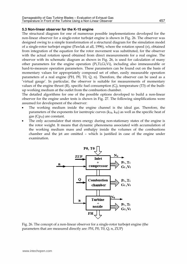
5.3 Non-linear observer for the K-15 engine The structural diagram for one of numerous possible implementations developed for the non-linear observer for a single-rotor turbojet engine is shown in Fig. 26. The observer was designed owing to a simple transformation of a structural diagram for the simulation model of a single-rotor turbojet engine (Pawlak at all, 1996), where the rotation speed (n), obtained from integration of the equation for the rotor movement was substituted, for the observer with the actual rotation speed obtained from direct measurements for a real engine. The observer with its schematic diagram as shown in Fig. 26, is used for calculation of many other parameters for the engine operation (Pi,Ti,Gi,Vi), including also immeasurable or hard-to-measure operation parameters. These parameters can be found out on the basis of momentary values for appropriately composed set of other, easily measurable operation parameters of a real engine (PH, P0, T0, Q, n). Therefore, the observer can be used as a ‘virtual gauge’. In particular, the observer is suitable for measurements of momentary values of the engine thrust (R), specific fuel consumption (Cj), temperature (T3) of the built-up working medium at the outlet from the combustion chamber. The detailed algorithms for one of the possible options developed to build a non-linear observer for the engine under tests is shown in Fig. 27. The following simplifications were assumed for development of the observer:
The working medium inside the engine channel is the ideal gas. Therefore, the parameters of the exponents for isentropic curves (k34, k45) as well as the specific heat of gas (Cp23) are constant.
The only accumulator that stores energy during non-stationary states of the engine is the rotor weight. It means that dynamic phenomena associated with accumulation of the working medium mass and enthalpy inside the volumes of the combustions chamber and the jet are omitted – which is justified in case of the engine under examination.
Fig. 26. The concept of a non-linear observer for a single-rotor turbojet engine (the parameters that are measured directly are: PH, P0, T0, Q, n, ZUP)
www.intechopen.com
Advances in Gas Turbine Technology
458
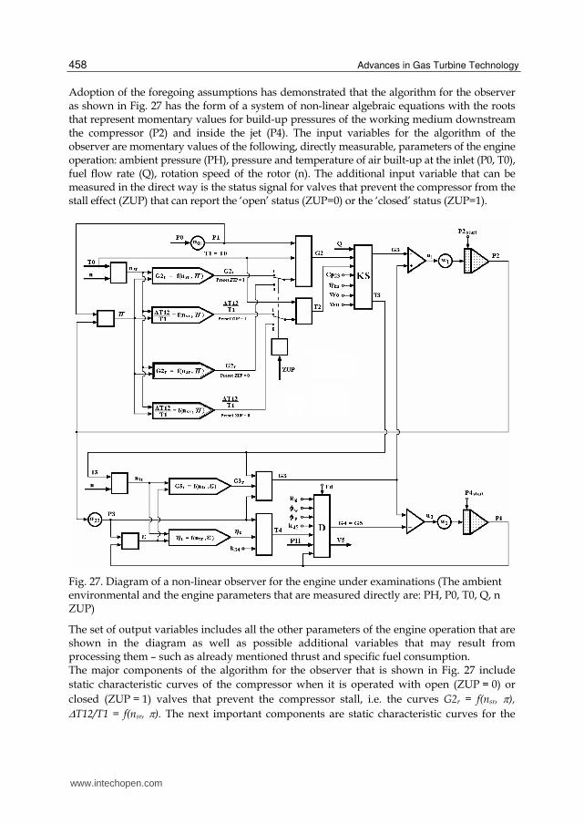
Adoption of the foregoing assumptions has demonstrated that the algorithm for the observer as shown in Fig. 27 has the form of a system of non-linear algebraic equations with the roots that represent momentary values for build-up pressures of the working medium downstream the compressor (P2) and inside the jet (P4). The input variables for the algorithm of the observer are momentary values of the following, directly measurable, parameters of the engine operation: ambient pressure (PH), pressure and temperature of air built-up at the inlet (P0, T0), fuel flow rate (Q), rotation speed of the rotor (n). The additional input variable that can be measured in the direct way is the status signal for valves that prevent the compressor from the stall effect (ZUP) that can report the ‘open’ status (ZUP=0) or the ‘closed’ status (ZUP=1).
Fig. 27. Diagram of a non-linear observer for the engine under examinations (The ambient environmental and the engine parameters that are measured directly are: PH, P0, T0, Q, n ZUP)
The set of output variables includes all the other parameters of the engine operation that are shown in the diagram as well as possible additional variables that may result from processing them – such as already mentioned thrust and specific fuel consumption. The major components of the algorithm for the observer that is shown in Fig. 27 include
static characteristic curves of the compressor when it is operated with open (ZUP = 0) or
closed (ZUP = 1) valves that prevent the compressor stall, i.e. the curves G2r = f(nsr, ),
T12/T1 = f(nsr, ). The next important components are static characteristic curves for the
www.intechopen.com

Damageability of Gas Turbine Blades – Evaluation of Exhaust Gas Temperature in Front of the Turbine Using a Non-Linear Observer
459
turbine: G3r = f(ntr, ) and t = f(ntr, ). Accuracy of the calculation results obtained with use
of the observer substantially depends on accuracy of the mentioned characteristic curves. The observer diagram from Fig. 27 illustrates in the graphic way how to seek the roots of the system equations by a series of iterations. The method convergence, and, consequently, the time in which the algorithm can be completed on a digital computer, depends on how well the gain coefficients (w1, w2), also shown in the diagram, are selected. The iteration process is finished when values of deviations (u1, u2) are sufficiently low, which is illustrated in the diagram.
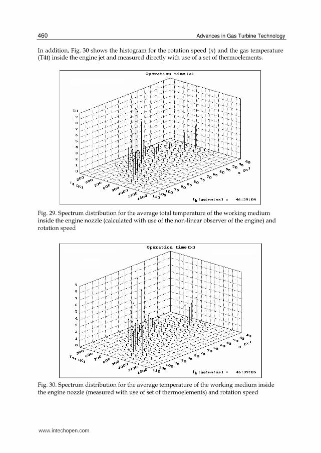
5.4 D spectrum of loads Particular attention must be paid to spectra of totalized thermal and mechanical loads affecting the so-called hot parts of the engine design structure. The loads are caused by simultaneous variations of both the rotor rotation speed (n) and the average total temperature of the working medium at the outlet of the combustion chamber (T3) and inside the jet (T4). In order to illustrate spectra of these loads it was necessary to develop 3-D histograms (Fig. 28 - 32). Fig. 28 shows the 3-D histogram for the actual average temperature (T3) of the exhaust gas at the outlet of the combustion chamber and the rotation speed (n), whilst Fig. 29 contains the similar diagram for the actual average temperature (T4) of the exhaust gas inside the engine jet and the rotation speed (n). One has to pay attention that both monitored temperatures belong to the category of immeasurable parameters and could have been tracked only with use of the already mentioned non-linear observer for the engine. Consequently, the interesting phenomenon could be found out, namely stabilization of the histogram shapes after expiring of about 30-40h when the engine operation was monitored.
Fig. 28. Spectrum distribution for the average total temperature for the working medium at the outlet of the combustion chamber (calculated with use of the non-linear observer of the engine) and rotation speed
www.intechopen.com
Advances in Gas Turbine Technology
460
In addition, Fig. 30 shows the histogram for the rotation speed (n) and the gas temperature (T4t) inside the engine jet and measured directly with use of a set of thermoelements.
Fig. 29. Spectrum distribution for the average total temperature of the working medium inside the engine nozzle (calculated with use of the non-linear observer of the engine) and rotation speed
Fig. 30. Spectrum distribution for the average temperature of the working medium inside the engine nozzle (measured with use of set of thermoelements) and rotation speed
www.intechopen.com
Damageability of Gas Turbine Blades – Evaluation of Exhaust Gas Temperature in Front of the Turbine Using a Non-Linear Observer
461
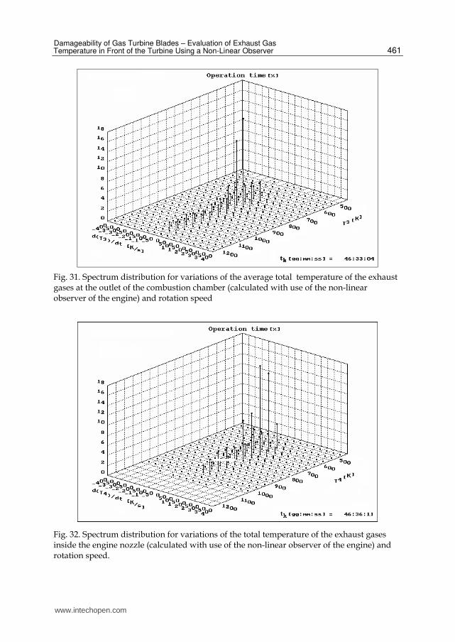
Fig. 31. Spectrum distribution for variations of the average total temperature of the exhaust gases at the outlet of the combustion chamber (calculated with use of the non-linear observer of the engine) and rotation speed
Fig. 32. Spectrum distribution for variations of the total temperature of the exhaust gases inside the engine nozzle (calculated with use of the non-linear observer of the engine) and rotation speed.
www.intechopen.com
Advances in Gas Turbine Technology
462
When thermal loads affecting the engine are subject to variations, it is crucial to know the rates of these variations. For that purpose the histograms presented in Fig. 31 and Fig. 32 were developed. These histograms show spectra for average temperatures of the working medium at the outlet of the combustion chamber (T3) and inside the engine nozzle (T4) together with their first derivatives (dT3/dt, dT4/dt). These histograms were also developed with use of the non-linear observer for the engine. Availability of spectral diagrams for specific types of engines (e.g. in the form of the foregoing histograms) makes it possible to accurately determine their degree of low-cycle wear in pace with the operation time. It also enables to precisely schedule the fatigue tests for materials that are used for the engine design as well as to draw up plans and carry out the so-called rapid tests for critically loaded components of the engine structures.
6. Conclusions
The destructive processes affecting gas turbine vanes and blades begins with destruction of
the aluminium coating. Consequently, the parent material of vanes and blades is exposed to
the direct thermal and chemical effects of exhaust gases. Such circumstances lead, first and
foremost, to the overheating of that material, which is manifested by adverse changes in the
material microstructure. The factors that influence that effect include the supercritical
temperature, the exposure time to the latter and chemical aggression of exhaust gases.
The comparative examinations of microstructures demonstrated by two blades, i.e. the new
and overheated one and the one that has been in operation, have led to the conclusion that
alterations of the damaged blade is a result of extension that happens to the intermetallic γ' phase. The size and shapes of that phase is comparable to the reciprocal parameters of the γ' phase for a new blade subjected to soaking to the temperature above 1223K for 1h. The
achieved results make it possible to conclude that the damaged turbine blade was operated
at the temperature of exhaust gases that exceeded the maximum allowed limit of 1013K for
the time of about 1h (i.e. the time comparable to the heating time of a new blade) during air
missions. Extension of the mentioned phase leads to coagulation of precipitates and changes
of particle shapes from cubical to plate one. It leads to drop of the heat resistance and creep
resistance parameters of the alloy.
Although the presented methodical approach to identification of reasons for failures of gas
turbine blades during the process of the turbine operation ignores mechanical loads that
occur during the turbine operation, it is sufficiently useful in case of engine defects when
information of its operation conditions is incomplete.
Nevertheless, although the metallographic examinations enable determination of the material microstructure in an unbiased, trustworthy and dependable manner, it is still a destructive examination method. That is why there is a need to develop a set of non-destructive diagnostic tests aimed at assessing technical condition of gas turbine blades when the machine is still in operation. Each of non-destructive diagnostic methods that have already been applied to diagnostics of technical structures features a specific performance and applicability to assessment of that condition. Therefore, a combination of these methods, aided by computer technologies and with application of artificial intelligence, offers supreme research opportunities, much wider than any of the single method. Such an examination program shall enable really unbiased, trustworthy and dependable assessment of actual condition demonstrated by gas turbine blades during the process of operation
www.intechopen.com

Damageability of Gas Turbine Blades – Evaluation of Exhaust Gas Temperature in Front of the Turbine Using a Non-Linear Observer
463
thereof against the three-threshold scale: applicability, partial (provisional) applicability and inapplicability. The non-linear observer for jet engines pretty well performs the role of a ‘virtual measuring gauge’ for immeasurable or hard-to-measure parameters. The basic hindrance that prevents the wider application of non-linear observers is the need to modify their structure as the time goes by in order to take into account slight variations of static characteristic curves for compressors and turbines of jet engines that occur in pace with the engine operation and result from natural wear and tear. It is the open problem that can become the topic of further research studies with a substantial practical impact. Familiarity with dynamic timings for momentary temperature values of the working medium is the matter of crucial importance for determination of low-cycle thermal fatigue affecting the critically loaded ‘hot’ components of the engine design – turbine blades and disks. Direct measurements of momentary temperature values for exhaust gases flowing via the turbine, when a set of thermoelements is applied, is burdened with a large and hard to compensate measurement error. The difficulty of compensation of such an error results from unavailability of a mathematical model that would be good enough to describe dynamic features of thermoelement operation. It is indispensable to undertake efforts in this area as the solutions that are available from literature sources are applicable only in a limited scope.
7. References
Antonelli, G.; Ruzzier, M. & Necci, F. (1998). Thickness measurement of MCrALY high-temperature coatings by frequency scanning eddy current technique. Journal of Engineering for Gas Turbines and Power, Transactions of ASME 120, pp. 537 – 542
Błachnio, J. (2004). Aircraft propulsion systems of the future. Journal of Transdisciplinary Systems Science, Vol. 9, pp. 29-37
Błachnio, J. (2007). Technical Analysis of Inefficiency and Failures of Aircrafts. Fundamentals of Aircraft Operation. Edited by J. Lewitowicz, J.: Publishing House of the Air Force Institute of Technology, Part. 4, pp. 181-264, ISBN 978-83-914337-9-X , Warsaw, Poland (in Polish)
Błachnio, J. & Bogdan, M. (2008) Diagnostics of the technical condition demonstrated by vanes of gas turbines. Diagnostics, No 1 (45), pp. 91-96, ISSN 641-6414
Błachnio, J. (2009). The effect of high temperature on the degradation of heat-resistantand high-temperature alloys. Journal Solid State Phenomena, Vol. 147-149, pp. 744 – 752, ISSN 1012-0394
Błachnio, J. (2010). Examination of changes in microstructure of turbine blades th the use of non-destructive methods. Journal of Polish CIMAC, Vol.5, nr 2, pp.17-28, ISBN 83-900666-2-9, ISSN 1231-3998
Bogdan, M. (2009). Diagnostic examinations of gas turbine blades by means of digital processing of their surface images. PhD Thesis, Technical University of Białystok, Białystok, Poland, (in Polish)
Hernas, A. (1999). Steel and Alloy High Temperature Creep Resistance, Part. 1. Publishing House of the Silesian University of Technology, Gliwice, Poland ISBN 83-88000-16-0 (in Polish)
Korczewski, Z. (2008). Archives of marine engines endoscopy, Publishing House of the Polish Navy University, Gdynia, Poland (in Polish)
www.intechopen.com

Advances in Gas Turbine Technology
464
Kroes, M. J.; Wild. T. W.; Bent, W. R. & Mc Kinley, J. L. (1992). Aircraft powerplants. Mc Graw- Hill
Majka, H. & Sieniawski, J. (1998). Examination of kinetic properties for extension and
coagulation of the ’ phase in a nickel superalloy EI-867. Archives of Science on Materials, vol. 19, No. 4, pp. 237-254 (in Polish)
Nikitin, W. I. (1987). Corrosion and Protection of Gas Turbine Vanes. Leningrad, Russia (in Russian)
Okrajni, J. & Plaza M. (1995). Simulation of the fracture process of materials subjected to low-cycle fatigue of mechanical and thermal character. Journal of Materials Processing Technology, ELSEVIER, pp. 311 - 318
Paton, B. (1997). High-temperature creep resistance of cast nickel-base alloys; corrosion protection thereof, Naukowa Dumka, Kijew, Russia (in Russian)
Pawlak, W.; Wiklik, K. & Morawski, J.M. (1996). Synthesis and Examination of Control Systems for Aircraft Turbine Engines with Use of the Computer Simulation Methods, Scientific Library of the Aviation Institute, Warsaw, Poland (in Polish)
Pawlak, W. I. (2003). Nonlinear observer in control system of a turbine jet engine. The Archive of Mechanical Engineering, Vol. L, Warsaw, Poland
Pawlak, W. I. (2005). A non-linear observer in the warning system indicating faulty modes of operation of a turbine jet engine. The Archive of Mechanical Engineering, Vol. LII, Warsaw, Poland
Pawlak, W. I. (2006). The effect of convergent-nozzle volume on transient processes in a turbojet engine. The Archive of Mechanical Engineering, Vol. LIII, Warsaw, Poland
Pawlak, W. I. (2007). Computer simulation of transient processes in a turbojet engine, with special attention to amplitudes of thermal shocks in some selected fault modes of operation. The Archive of Mechanical Engineering, Vol. LIV, Warsaw, Poland
Pawlak, W. I. & Spychała, J. (2007). Performance of the advanced and simplified variants of a non-linear observer of a turbojet engine, comparison of results. Journal of Polish CIMAC, Gdańsk- Stockholm-Tumba, Poland-Sweden
Poznańska, A. (1995). Lifetime of blades made of the EI-867 alloy and used for aircraft engines at the aspect of non-uniform deformation and structural alterations, PhD Thesis, University of Technology in Rzeszów, Poland (in Polish)
Reports, (2000-2010) of Division of Aircraft Engines, Air Force Institute of Technology, Warsaw, Poland
Sieniawski, J. (1995). Assessment criteria and methods applicable to materials for components of turbine engines, Publishing House of the University of Technology in Rzeszów, Poland (in Polish)
Swadźba, L. (2007). Development of desired structures and properties demonstrated by protective coatings on selected alloys used for aircraft turbine engines, Publishing House of the Silesian University of Technology, Katowice, Poland (in Polish)
Taira, S. & Otani, R. (1986). Theories for high-temperature strength of materials, Moscow, Russia (in Russian)
Tomkins, B. (1981). Creep and fatigue in high temperature alloys, Ed. Bressers J., Applied Science Publishers, London,
www.intechopen.com
Advances in Gas Turbine TechnologyEdited by Dr. Ernesto Benini
ISBN 978-953-307-611-9Hard cover, 526 pagesPublisher InTechPublished online 04, November, 2011Published in print edition November, 2011
InTech EuropeUniversity Campus STeP Ri Slavka Krautzeka 83/A 51000 Rijeka, Croatia Phone: +385 (51) 770 447 Fax: +385 (51) 686 166www.intechopen.com
InTech ChinaUnit 405, Office Block, Hotel Equatorial Shanghai No.65, Yan An Road (West), Shanghai, 200040, China
Phone: +86-21-62489820 Fax: +86-21-62489821
Gas turbine engines will still represent a key technology in the next 20-year energy scenarios, either in stand-alone applications or in combination with other power generation equipment. This book intends in fact toprovide an updated picture as well as a perspective vision of some of the major improvements thatcharacterize the gas turbine technology in different applications, from marine and aircraft propulsion toindustrial and stationary power generation. Therefore, the target audience for it involves design, analyst,materials and maintenance engineers. Also manufacturers, researchers and scientists will benefit from thetimely and accurate information provided in this volume. The book is organized into five main sectionsincluding 21 chapters overall: (I) Aero and Marine Gas Turbines, (II) Gas Turbine Systems, (III) Heat Transfer,(IV) Combustion and (V) Materials and Fabrication.
How to referenceIn order to correctly reference this scholarly work, feel free to copy and paste the following:
Jo ́zef Błachnio and Wojciech Izydor Pawlak (2011). Damageability of Gas Turbine Blades – Evaluation ofExhaust Gas Temperature in Front of the Turbine Using a Non-Linear Observer, Advances in Gas TurbineTechnology, Dr. Ernesto Benini (Ed.), ISBN: 978-953-307-611-9, InTech, Available from:http://www.intechopen.com/books/advances-in-gas-turbine-technology/damageability-of-gas-turbine-blades-evaluation-of-exhaust-gas-temperature-in-front-of-the-turbine-us

© 2011 The Author(s). Licensee IntechOpen. This is an open access articledistributed under the terms of the Creative Commons Attribution 3.0License, which permits unrestricted use, distribution, and reproduction inany medium, provided the original work is properly cited.